1
M160 Internet Router
Hardware Guide
Juniper Networks®, Inc.
1194 North Mathilda Avenue
Sunnyvale, California
94089
USA
408-745-2000
www.juniper.net
Part Number: 530-007250-01, Revision 5
This product includes the Envoy SNMP Engine, developed by Epilogue Technology, an Integrated Systems Company. Copyright
© 1986-1997, Epilogue Technology Corporation. All rights reserved. This program and its documentation were developed
at private expense, and no part of them is in the public domain.
This product includes memory allocation software developed by Mark Moraes, copyright © 1988, 1989, 1993, University of Toronto.
This product includes FreeBSD software developed by the University of California, Berkeley, and its contributors. All of the documentation and
software included in the 4.4BSD and 4.4BSD-Lite Releases is copyrighted by the Regents of the University of California. Copyright © 1979, 1980,
1983, 1986, 1988, 1989, 1991, 1992, 1993, 1994. The Regents of the University of California. All rights reserved.
GateD software copyright © 1995, the Regents of the University. All rights reserved. Gate Daemon was originated and developed through release
3.0 by Cornell University and its collaborators. Gated is based on Kirton’s EGP, UC Berkeley’s routing daemon (routed), and DCN’s HELLO routing
protocol. Development of Gated has been supported in part by the National Science Foundation. Portions of the GateD software copyright © 1988,
Regents of the University of California. All rights reserved. Portions of the GateD software copyright © 1991, D. L. S. Associates.
This product includes software developed by Maker Communications, Inc., Copyright © 1996, 1997, Maker Communications, Inc.
Juniper Networks, the Juniper Networks logo, NetScreen, NetScreen Technologies, the NetScreen logo, NetScreen-Global Pro, ScreenOS, and
GigaScreen are registered trademarks of Juniper Networks, Inc. in the United States and other countries.
The following are trademarks of Juniper Networks, Inc.: ERX, ESP, E-series, Instant Virtual Extranet, Internet Processor, J2300, J4300, J6300, J-Protect,
J-series, J-Web, JUNOS, JUNOScope, JUNOScript, JUNOSe, M5, M7i, M10, M10i, M20, M40, M40e, M160, M320, M-series, MMD, NetScreen-5GT,
NetScreen-5XP, NetScreen-5XT, NetScreen-25, NetScreen-50, NetScreen-204, NetScreen-208, NetScreen-500, NetScreen-5200, NetScreen-5400,
NetScreen-IDP 10, NetScreen-IDP 100, NetScreen-IDP 500, NetScreen-Remote Security Client, NetScreen-Remote VPN Client, NetScreen-SA 1000 Series,
NetScreen-SA 3000 Series, NetScreen-SA 5000 Series, NetScreen-SA Central Manager, NetScreen Secure Access, NetScreen-SM 3000, NetScreen-Security
Manager, NMC-RX, SDX, Stateful Signature, T320, T640, T-series, and TX Matrix. All other trademarks, service marks, registered trademarks, or
registered service marks are the property of their respective owners. All specifications are subject to change without notice.
Juniper Networks assumes no responsibility for any inaccuracies in this document. Juniper Networks reserves the right to
change, modify, transfer, or otherwise revise this publication without notice.
Copyright © 2005, Juniper Networks, Inc. All rights reserved.
M160 Internet Router Hardware Guide
Copyright © 2005, Juniper Networks, Inc.
All rights reserved. Printed in USA.
Writing: Sheila Nolte, Tony Mauro, Jerry Isaac
Editing: Stella Hackell
Illustration: Faith Bradford
Cover Design: Edmonds Design
Revision History
25 February 2005—530-007250-01 Revision 5. Correct DC power illustration and replacement procedure.
12 November 2004—530-007250-01 Revision 4. Revised fuse replacement procedure.
30 June 2003—530-007250-01 Revision 3. Corrected and added component information.
15 October 2002—530-007250-01 Revision 2. Incorporated updated technical information; synchronized with M40e Internet Router Hardware Guide.
15 March 2002—530-007250-01 Revision 1. Incorporated updated technical information.
15 October 2001—Incorporated updated technical information.
15 May 2001—Adopted new template.
28 February 2001—Incorporated updated technical information.
31 August 2000—Incorporated updated technical information.
31 March 2000—First edition.
The information in this document is current as of the date listed in the revision history.
Juniper Networks assumes no responsibility for any inaccuracies in this document. Juniper Networks reserves the right to change, modify, transfer or
otherwise revise this publication without notice.
Products made or sold by Juniper Networks (including the ERX-310, ERX-705, ERX-710, ERX-1410, ERX-1440, M5, M7i, M10, M10i, M20, M40, M40e,
M160, M320, and T320 routers, T640 routing node, and the JUNOS and SDX-300 software) or components thereof might be covered by one or more of the
following patents that are owned by or licensed to Juniper Networks: U.S. Patent Nos. 5,473,599, 5,905,725, 5,909,440, 6,192,051, 6,333,650, 6,359,479,
6,406,312, 6,429,706, 6,459,579, 6,493,347, 6,538,518, 6,538,899, 6,552,918, 6,567,902, 6,578,186, and 6,590,785.
YEAR 2000 NOTICE
Juniper Networks hardware and software products are Year 2000 compliant. The JUNOS software has no known time-related limitations through the year
2038. However, the NTP application is known to have some difficulty in the year 2036.
ii
End User License Agreement
READ THIS END USER LICENSE AGREEMENT ("AGREEMENT") BEFORE DOWNLOADING, INSTALLING, OR USING THE SOFTWARE. BY DOWNLOADING,
INSTALLING, OR USING THE SOFTWARE OR OTHERWISE EXPRESSING YOUR AGREEMENT TO THE TERMS CONTAINED HEREIN, YOU (AS CUSTOMER
OR IF YOU ARE NOT THE CUSTOMER, AS A REPRESENTATIVE/AGENT AUTHORIZED TO BIND THE CUSTOMER) CONSENT TO BE BOUND BY THIS
AGREEMENT. IF YOU DO NOT OR CANNOT AGREE TO THE TERMS CONTAINED HEREIN, THEN (A) DO NOT DOWNLOAD, INSTALL, OR USE THE
SOFTWARE, AND (B) YOU MAY CONTACT JUNIPER NETWORKS REGARDING LICENSE TERMS.
1.
The Parties. The parties to this Agreement are Juniper Networks, Inc. and its subsidiaries (collectively "Juniper"), and the person or organization that
originally purchased from Juniper or an authorized Juniper reseller the applicable license(s) for use of the Software ("Customer") (collectively, the "Parties").
2.
The Software. In this Agreement, "Software" means the program modules and features of the Juniper or Juniper-supplied software, and updates and
releases of such software, for which Customer has paid the applicable license or support fees to Juniper or an authorized Juniper reseller.
3.
License Grant. Subject to payment of the applicable fees and the limitations and restrictions set forth herein, Juniper grants to Customer a
non-exclusive and non-transferable license, without right to sublicense, to use the Software, in executable form only, subject to the following use restrictions:
a.
Customer shall use the Software solely as embedded in, and for execution on, Juniper equipment originally purchased by Customer from
Juniper or an authorized Juniper reseller, unless the applicable Juniper documentation expressly permits installation on non-Juniper equipment.
b.
Customer shall use the Software on a single hardware chassis having a single processing unit, or as many chassis or processing
units for which Customer has paid the applicable license fees.
c.
Other Juniper documentation for the Software (such as product purchase documents, documents accompanying the product, the
Software user manual(s), Juniper’s website for the Software, or messages displayed by the Software) may specify limits to Customer’s use of the
Software. Such limits may restrict use to a maximum number of seats, concurrent users, sessions, subscribers, nodes, or transactions, or
require the purchase of separate licenses to use particular features, functionalities, or capabilities, or provide temporal or geographical limits.
Customer’s use of the Software shall be subject to all such limitations and purchase of all applicable licenses.
The foregoing license is not transferable or assignable by Customer. No license is granted herein to any user who did not originally purchase
the applicable license(s) for the Software from Juniper or an authorized Juniper reseller.
4.
Use Prohibitions. Notwithstanding the foregoing, the license provided herein does not permit the Customer to, and Customer agrees not to and shall
not: (a) modify, unbundle, reverse engineer, or create derivative works based on the Software; (b) make unauthorized copies of the Software (except as
necessary for backup purposes); (c) rent, transfer, or grant any rights in and to any copy of the Software, in any form, to any third party; (d) remove any
proprietary notices, labels, or marks on or in any copy of the Software; (e) distribute any copy of the Software to any third party, including as may be
embedded in Juniper equipment sold in the secondhand market; (f) use any ’locked’ or key-restricted feature, function, or capability without first purchasing
the applicable license(s) and obtaining a valid key from Juniper, even if such feature, function, or capability is enabled without a key; (g) distribute any key
for the Software provided by Juniper to any third party; (h) use the Software in any manner that extends or is broader than the uses purchased by Customer
from Juniper or an authorized Juniper reseller; (i) use the Software on non-Juniper equipment where the Juniper documentation does not expressly permit
installation on non-Juniper equipment; (j) use the Software (or make it available for use) on Juniper equipment that the Customer did not originally purchase
from Juniper or an authorized Juniper reseller; or (k) use the Software in any manner other than as expressly provided herein.
5.
Audit. Customer shall maintain accurate records as necessary to verify compliance with this Agreement. Upon request by Juniper, Customer shall
furnish such records to Juniper and certify its compliance with this Agreement.
6.
Confidentiality. The Parties agree that aspects of the Software and associated documentation are the confidential property of Juniper. As such,
Customer shall exercise all reasonable commercial efforts to maintain the Software and associated documentation in confidence, which at a minimum
includes restricting access to the Software to Customer employees and contractors having a need to use the Software.
7.
Ownership. Juniper and Juniper’s licensors, respectively, retain ownership of all right, title, and interest (including copyright) in and to the Software,
associated documentation, and all copies of the Software. Nothing in this Agreement constitutes a transfer or conveyance of any right, title, or interest in
the Software or associated documentation, or a sale of the Software, associated documentation, or copies of the Software.
8.
Warranty, Limitation of Liability, Disclaimer of Warranty. If the Software is distributed on physical media (such as CD), Juniper warrants for 90 days
from delivery that the media on which the Software is delivered will be free of defects in material and workmanship under normal use. This limited
warranty extends only to the Customer. Except as may be expressly provided in separate documentation from Juniper, no other warranties apply to
the Software, and the Software is otherwise provided AS IS. Customer assumes all risks arising from use of the Software. Customer’s sole remedy and
Juniper’s entire liability under this limited warranty is that Juniper, at its option, will repair or replace the media containing the Software, or provide a
refund, provided that Customer makes a proper warranty claim to Juniper, in writing, within the warranty period. Nothing in this Agreement shall give rise
to any obligation to support the Software. Any such support shall be governed by a separate, written agreement. To the maximum extent permitted by law,
Juniper shall not be liable for any liability for lost profits, loss of data or costs or procurement of substitute goods or services, or for any special, indirect, or
consequential damages arising out of this Agreement, the Software, or any Juniper or Juniper-supplied software. In no event shall Juniper be liable for
damages arising from unauthorized or improper use of any Juniper or Juniper-supplied software.
EXCEPT AS EXPRESSLY PROVIDED HEREIN OR IN SEPARATE DOCUMENTATION PROVIDED FROM JUNIPER AND TO THE EXTENT PERMITTED BY
LAW, JUNIPER DISCLAIMS ANY AND ALL WARRANTIES IN AND TO THE SOFTWARE (WHETHER EXPRESS, IMPLIED, STATUTORY, OR OTHERWISE),
INCLUDING ANY IMPLIED WARRANTY OF MERCHANTABILITY, FITNESS FOR A PARTICULAR PURPOSE, OR NONINFRINGEMENT. IN NO EVENT DOES
iii
JUNIPER WARRANT THAT THE SOFTWARE, OR ANY EQUIPMENT OR NETWORK RUNNING THE SOFTWARE, WILL OPERATE WITHOUT ERROR OR
INTERRUPTION, OR WILL BE FREE OF VULNERABILITY TO INTRUSION OR ATTACK.
9.
Termination. Any breach of this Agreement or failure by Customer to pay any applicable fees due shall result in automatic termination of the
license granted herein. Upon such termination, Customer shall destroy or return to Juniper all copies of the Software and related documentation in
Customer’s possession or control.
10.
Taxes. All license fees for the Software are exclusive of taxes, withholdings, duties, or levies (collectively "Taxes"). Customer shall be responsible
for paying Taxes arising from the purchase of the license, or importation or use of the Software.
11.
Export. Customer agrees to comply with all applicable export laws and restrictions and regulations of any United States and any applicable foreign
agency or authority, and not to export or re-export the Software or any direct product thereof in violation of any such restrictions, laws or regulations, or
without all necessary approvals. Customer shall be liable for any such violations. The version of the Software supplied to you may contain encryption or
other capabilities restricting your ability to export the Software without an export license.
12.
Commercial Computer Software. The Software is "commercial computer software" and is provided with restricted rights. Use, duplication, or
disclosure by the United States government is subject to restrictions set forth in this Agreement and as provided in DFARS 227.7201 through 227.7202-4,
FAR 12.212, FAR 27.405(b)(2), FAR 52.227-19, or FAR 52.227-14(ALT III) as applicable.
13.
Miscellaneous. This Agreement shall be governed by the laws of the State of California without reference to its conflicts of laws principles. For any
disputes arising under this Agreement, the Parties hereby consent to the personal and exclusive jurisdiction of, and venue in, the state and federal courts
within Santa Clara County, California. This Agreement constitutes the entire and sole agreement between Juniper and the Customer with respect to the
Software, and supersedes all prior and contemporaneous agreements relating to the Software, whether oral or written (including any inconsistent terms
contained in a purchase order), except that the terms of a separate written agreement executed by an authorized Juniper representative and Customer
shall govern to the extent such terms are inconsistent or conflict with terms contained herein. No modification to this Agreement nor any waiver of any
rights hereunder shall be effective unless expressly assented to in writing by the party to be charged. If any portion of this Agreement is held invalid, the
Parties agree that such invalidity shall not affect the validity of the remainder of this Agreement.
If you have any questions about this agreement, contact Juniper Networks at the following address:
Juniper Networks, Inc.
1194 North Mathilda Avenue
Sunnyvale, CA 94089
USA
Attn: Contracts Administrator
iv
Table of Contents
About This Guide
xix
Objectives .. .. .. .. .. .. .. .. .. .. .. .. .. .. .. .. .. .. .. .. .. .. .. .. .. .. .. .. .. .. .. .. .. .. .. .. .. .xix
Audience.. .. .. .. .. .. .. .. .. .. .. .. .. .. .. .. .. .. .. .. .. .. .. .. .. .. .. .. .. .. .. .. .. .. .. .. .. .. .xix
Documentation Conventions . .. .. .. .. .. .. .. .. .. .. .. .. .. .. .. .. .. .. .. .. .. .. .. .. .. .. .xix
List of Technical Publications . .. .. .. .. .. .. .. .. .. .. .. .. .. .. .. .. .. .. .. .. .. .. .. .. .. .. .xxi
Documentation Feedback . .. .. .. .. .. .. .. .. .. .. .. .. .. .. .. .. .. .. .. .. .. .. .. .. .. .. .. . xxiii
Requesting Support.. .. .. .. .. .. .. .. .. .. .. .. .. .. .. .. .. .. .. .. .. .. .. .. .. .. .. .. .. .. .. . xxiii
Part 1
Product Overview
Chapter 1
System Overview ..
3
System Description .. .. .. .. .. .. .. .. .. .. .. .. .. .. .. .. .. .. .. .. .. .. .. .. .. .. .. .. .. .. .. .. .. .3
Field-Replaceable Units (FRUs) . .. .. .. .. .. .. .. .. .. .. .. .. .. .. .. .. .. .. .. .. .. .. .. .. .. .. .4
System Redundancy. .. .. .. .. .. .. .. .. .. .. .. .. .. .. .. .. .. .. .. .. .. .. .. .. .. .. .. .. .. .. .. .. .4
Safety Requirements, Warnings, and Guidelines .. .. .. .. .. .. .. .. .. .. .. .. .. .. .. .. .. .5
Chapter 2
Hardware Component Overview..
7
Chassis.. .. .. .. .. .. .. .. .. .. .. .. .. .. .. .. .. .. .. .. .. .. .. .. .. .. .. .. .. .. .. .. .. .. .. .. .. .. .. .. .7
Packet Forwarding Engine .. .. .. .. .. .. .. .. .. .. .. .. .. .. .. .. .. .. .. .. .. .. .. .. .. .. .. .. ..11
Midplane. .. .. .. .. .. .. .. .. .. .. .. .. .. .. .. .. .. .. .. .. .. .. .. .. .. .. .. .. .. .. .. .. .. .. .. . 12
Physical Interface Cards (PICs). .. .. .. .. .. .. .. .. .. .. .. .. .. .. .. .. .. .. .. .. .. .. .. . 13
PIC Components . .. .. .. .. .. .. .. .. .. .. .. .. .. .. .. .. .. .. .. .. .. .. .. .. .. .. .. .. . 14
Flexible PIC Concentrators (FPCs) . .. .. .. .. .. .. .. .. .. .. .. .. .. .. .. .. .. .. .. .. .. . 14
FPC Components. .. .. .. .. .. .. .. .. .. .. .. .. .. .. .. .. .. .. .. .. .. .. .. .. .. .. .. .. . 16
FPC Types. .. .. .. .. .. .. .. .. .. .. .. .. .. .. .. .. .. .. .. .. .. .. .. .. .. .. .. .. .. .. .. .. . 17
Packet Forwarding Engine Clock Generators (PCGs) . .. .. .. .. .. .. .. .. .. .. .. . 18
PCG Components .. .. .. .. .. .. .. .. .. .. .. .. .. .. .. .. .. .. .. .. .. .. .. .. .. .. .. .. . 19
Switching and Forwarding Module (SFM) . .. .. .. .. .. .. .. .. .. .. .. .. .. .. .. .. .. . 19
SFM Components .. .. .. .. .. .. .. .. .. .. .. .. .. .. .. .. .. .. .. .. .. .. .. .. .. .. .. .. . 20
Host Module.. .. .. .. .. .. .. .. .. .. .. .. .. .. .. .. .. .. .. .. .. .. .. .. .. .. .. .. .. .. .. .. .. .. .. .. . 22
Routing Engine .. .. .. .. .. .. .. .. .. .. .. .. .. .. .. .. .. .. .. .. .. .. .. .. .. .. .. .. .. .. .. .. . 23
Routing Engine Components.. .. .. .. .. .. .. .. .. .. .. .. .. .. .. .. .. .. .. .. .. .. . 24
Miscellaneous Control Subsystem (MCS).. .. .. .. .. .. .. .. .. .. .. .. .. .. .. .. .. .. . 25
MCS Components .. .. .. .. .. .. .. .. .. .. .. .. .. .. .. .. .. .. .. .. .. .. .. .. .. .. .. .. . 26
Craft Interface.. .. .. .. .. .. .. .. .. .. .. .. .. .. .. .. .. .. .. .. .. .. .. .. .. .. .. .. .. .. .. .. .. .. .. . 27
Alarm LEDs and Alarm Cutoff/Lamp Test Button. .. .. .. .. .. .. .. .. .. .. .. .. .. . 28
LCD and Navigation Buttons . .. .. .. .. .. .. .. .. .. .. .. .. .. .. .. .. .. .. .. .. .. .. .. .. . 29
LCD Idle Mode.. .. .. .. .. .. .. .. .. .. .. .. .. .. .. .. .. .. .. .. .. .. .. .. .. .. .. .. .. .. . 29
LCD Alarm Mode . .. .. .. .. .. .. .. .. .. .. .. .. .. .. .. .. .. .. .. .. .. .. .. .. .. .. .. .. . 30
Table of Contents
v
M160 Internet Router Hardware Guide
Host Module LEDs .. .. .. .. .. .. .. .. .. .. .. .. .. .. .. .. .. .. .. .. .. .. .. .. .. .. .. .. .. .. . 31
FPC LEDs and Offline Button .. .. .. .. .. .. .. .. .. .. .. .. .. .. .. .. .. .. .. .. .. .. .. .. . 31
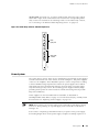
Connector Interface Panel (CIP) .. .. .. .. .. .. .. .. .. .. .. .. .. .. .. .. .. .. .. .. .. .. .. .. .. . 32
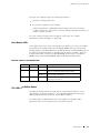
Routing Engine Management Ports.. .. .. .. .. .. .. .. .. .. .. .. .. .. .. .. .. .. .. .. .. . 33
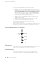
BITS Input Ports . .. .. .. .. .. .. .. .. .. .. .. .. .. .. .. .. .. .. .. .. .. .. .. .. .. .. .. .. .. .. .. . 34
Alarm Relay Contacts. .. .. .. .. .. .. .. .. .. .. .. .. .. .. .. .. .. .. .. .. .. .. .. .. .. .. .. .. . 34
Power System .. .. .. .. .. .. .. .. .. .. .. .. .. .. .. .. .. .. .. .. .. .. .. .. .. .. .. .. .. .. .. .. .. .. .. . 35
Power Supply .. .. .. .. .. .. .. .. .. .. .. .. .. .. .. .. .. .. .. .. .. .. .. .. .. .. .. .. .. .. .. .. .. . 36
Circuit Breaker Box . .. .. .. .. .. .. .. .. .. .. .. .. .. .. .. .. .. .. .. .. .. .. .. .. .. .. .. .. .. . 38
Fuses . .. .. .. .. .. .. .. .. .. .. .. .. .. .. .. .. .. .. .. .. .. .. .. .. .. .. .. .. .. .. .. .. .. .. .. .. .. . 39
Cooling System .. .. .. .. .. .. .. .. .. .. .. .. .. .. .. .. .. .. .. .. .. .. .. .. .. .. .. .. .. .. .. .. .. .. . 39
Cooling System Components .. .. .. .. .. .. .. .. .. .. .. .. .. .. .. .. .. .. .. .. .. .. .. .. . 40
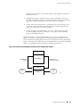
Airflow through the Chassis .. .. .. .. .. .. .. .. .. .. .. .. .. .. .. .. .. .. .. .. .. .. .. .. .. . 40
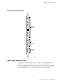
Cable Management System . .. .. .. .. .. .. .. .. .. .. .. .. .. .. .. .. .. .. .. .. .. .. .. .. .. .. .. . 41
Chapter 3
JUNOS Internet Software Overview ..
43
Routing Engine Software Components. .. .. .. .. .. .. .. .. .. .. .. .. .. .. .. .. .. .. .. .. .. . 43
Routing Protocol Process . .. .. .. .. .. .. .. .. .. .. .. .. .. .. .. .. .. .. .. .. .. .. .. .. .. .. . 44
IPv4 Routing Protocols. .. .. .. .. .. .. .. .. .. .. .. .. .. .. .. .. .. .. .. .. .. .. .. .. .. . 44
IPv6 Routing Protocols. .. .. .. .. .. .. .. .. .. .. .. .. .. .. .. .. .. .. .. .. .. .. .. .. .. . 46
Routing and Forwarding Tables . .. .. .. .. .. .. .. .. .. .. .. .. .. .. .. .. .. .. .. .. . 47
Routing Policy .. .. .. .. .. .. .. .. .. .. .. .. .. .. .. .. .. .. .. .. .. .. .. .. .. .. .. .. .. .. . 47
VPNs . .. .. .. .. .. .. .. .. .. .. .. .. .. .. .. .. .. .. .. .. .. .. .. .. .. .. .. .. .. .. .. .. .. .. .. .. .. . 48
Interface Process .. .. .. .. .. .. .. .. .. .. .. .. .. .. .. .. .. .. .. .. .. .. .. .. .. .. .. .. .. .. .. . 49
Chassis Process . .. .. .. .. .. .. .. .. .. .. .. .. .. .. .. .. .. .. .. .. .. .. .. .. .. .. .. .. .. .. .. . 49
SNMP and MIB II Processes .. .. .. .. .. .. .. .. .. .. .. .. .. .. .. .. .. .. .. .. .. .. .. .. .. . 49
Management Process . .. .. .. .. .. .. .. .. .. .. .. .. .. .. .. .. .. .. .. .. .. .. .. .. .. .. .. .. . 49
Routing Engine Kernel.. .. .. .. .. .. .. .. .. .. .. .. .. .. .. .. .. .. .. .. .. .. .. .. .. .. .. .. . 49
Tools for Accessing and Configuring the Software .. .. .. .. .. .. .. .. .. .. .. .. .. .. .. . 50
Tools for Monitoring the Software .. .. .. .. .. .. .. .. .. .. .. .. .. .. .. .. .. .. .. .. .. .. .. .. . 50
Software Upgrades. .. .. .. .. .. .. .. .. .. .. .. .. .. .. .. .. .. .. .. .. .. .. .. .. .. .. .. .. .. .. .. .. . 50
Chapter 4
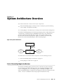
System Architecture Overview ..
51
Packet Forwarding Engine Architecture .. .. .. .. .. .. .. .. .. .. .. .. .. .. .. .. .. .. .. .. .. . 51
Data Flow through the Packet Forwarding Engine . .. .. .. .. .. .. .. .. .. .. .. .. . 52
Routing Engine Architecture .. .. .. .. .. .. .. .. .. .. .. .. .. .. .. .. .. .. .. .. .. .. .. .. .. .. .. . 53
Routing Engine Functions .. .. .. .. .. .. .. .. .. .. .. .. .. .. .. .. .. .. .. .. .. .. .. .. .. .. . 54
Part 2
Initial Installation
Chapter 5
vi
Table of Contents
Preparing for Router Installation . .
59
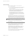
Rack Requirements .. .. .. .. .. .. .. .. .. .. .. .. .. .. .. .. .. .. .. .. .. .. .. .. .. .. .. .. .. .. .. .. . 59
Rack Size and Strength . .. .. .. .. .. .. .. .. .. .. .. .. .. .. .. .. .. .. .. .. .. .. .. .. .. .. .. . 60
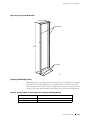
Spacing of Mounting Holes. .. .. .. .. .. .. .. .. .. .. .. .. .. .. .. .. .. .. .. .. .. .. .. .. .. . 61
Connection to Building Structure .. .. .. .. .. .. .. .. .. .. .. .. .. .. .. .. .. .. .. .. .. .. . 62
Clearance Requirements for Airflow and Hardware Maintenance . .. .. .. .. .. .. . 62
Routing Node Environmental Specifications .. .. .. .. .. .. .. .. .. .. .. .. .. .. .. .. .. .. . 62
Fire Safety Requirements . .. .. .. .. .. .. .. .. .. .. .. .. .. .. .. .. .. .. .. .. .. .. .. .. .. .. .. .. . 63
Table of Contents
Fire Suppression .. .. .. .. .. .. .. .. .. .. .. .. .. .. .. .. .. .. .. .. .. .. .. .. .. .. .. .. .. .. .. . 63
Fire Suppression Equipment . .. .. .. .. .. .. .. .. .. .. .. .. .. .. .. .. .. .. .. .. .. .. .. .. . 64
Power Guidelines, Requirements, and Specifications . .. .. .. .. .. .. .. .. .. .. .. .. .. . 64
Site Electrical Wiring Guidelines . .. .. .. .. .. .. .. .. .. .. .. .. .. .. .. .. .. .. .. .. .. .. . 65
Distance Limitations for Signaling .. .. .. .. .. .. .. .. .. .. .. .. .. .. .. .. .. .. .. . 65
Radio Frequency Interference. .. .. .. .. .. .. .. .. .. .. .. .. .. .. .. .. .. .. .. .. .. . 65
Electromagnetic Compatibility .. .. .. .. .. .. .. .. .. .. .. .. .. .. .. .. .. .. .. .. .. . 65
Router Power Requirements . .. .. .. .. .. .. .. .. .. .. .. .. .. .. .. .. .. .. .. .. .. .. .. .. . 65
Chassis Grounding .. .. .. .. .. .. .. .. .. .. .. .. .. .. .. .. .. .. .. .. .. .. .. .. .. .. .. .. .. .. . 67
Power, Connection, and Cable Specifications. .. .. .. .. .. .. .. .. .. .. .. .. .. .. .. . 67
Network Cable Specifications and Guidelines . .. .. .. .. .. .. .. .. .. .. .. .. .. .. .. .. .. . 70
Fiber Optic and Network Cable Specifications . .. .. .. .. .. .. .. .. .. .. .. .. .. .. . 71
Signal Loss in Multimode and Single-Mode Fiber-Optic Cable .. .. .. .. .. .. . 71
Attenuation and Dispersion in Fiber-Optic Cable .. .. .. .. .. .. .. .. .. .. .. .. .. . 71
Calculating Power Budget for Fiber-Optic Cable .. .. .. .. .. .. .. .. .. .. .. .. .. .. . 72
Calculating Power Margin for Fiber-Optic Cable .. .. .. .. .. .. .. .. .. .. .. .. .. .. . 73
Attenuating to Prevent Saturation at SONET/SDH PICs .. .. .. .. .. .. .. .. .. .. . 74
Routing Engine Interface Cable and Wire Specifications . .. .. .. .. .. .. .. .. .. .. .. . 74
Site Preparation Checklist . .. .. .. .. .. .. .. .. .. .. .. .. .. .. .. .. .. .. .. .. .. .. .. .. .. .. .. .. . 75
Chapter 6
Unpacking the Router ..
77
Tools and Parts Required .. .. .. .. .. .. .. .. .. .. .. .. .. .. .. .. .. .. .. .. .. .. .. .. .. .. .. .. .. . 77
Unpacking the Router . .. .. .. .. .. .. .. .. .. .. .. .. .. .. .. .. .. .. .. .. .. .. .. .. .. .. .. .. .. .. . 77
Chapter 7
Installing the Router Using a Mechanical Lift. .
81
Tools and Parts Required . .. .. .. .. .. .. .. .. .. .. .. .. .. .. .. .. .. .. .. .. .. .. .. .. .. .. .. .. . 81
Installing the Chassis Using a Mechanical Lift . .. .. .. .. .. .. .. .. .. .. .. .. .. .. .. .. .. . 81
Chapter 8
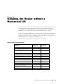
Installing the Router without a Mechanical Lift ..
83
Tools and Parts Required . .. .. .. .. .. .. .. .. .. .. .. .. .. .. .. .. .. .. .. .. .. .. .. .. .. .. .. .. . 84
Removing Components from the Chassis . .. .. .. .. .. .. .. .. .. .. .. .. .. .. .. .. .. .. .. . 84
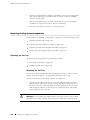
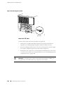
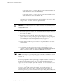
Removing the Power Supplies . .. .. .. .. .. .. .. .. .. .. .. .. .. .. .. .. .. .. .. .. .. .. .. . 86
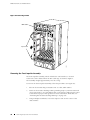
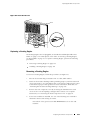
Removing the Rear Component Cover .. .. .. .. .. .. .. .. .. .. .. .. .. .. .. .. .. .. .. . 86
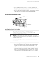
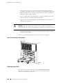
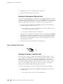
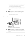
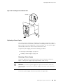
Removing the SFMs. .. .. .. .. .. .. .. .. .. .. .. .. .. .. .. .. .. .. .. .. .. .. .. .. .. .. .. .. .. . 87
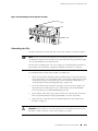
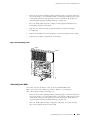
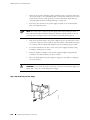
Removing the MCSs .. .. .. .. .. .. .. .. .. .. .. .. .. .. .. .. .. .. .. .. .. .. .. .. .. .. .. .. .. . 88
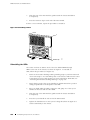
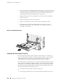
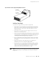
Removing the PCGs. .. .. .. .. .. .. .. .. .. .. .. .. .. .. .. .. .. .. .. .. .. .. .. .. .. .. .. .. .. . 89
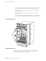
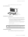
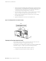
Removing the Routing Engines .. .. .. .. .. .. .. .. .. .. .. .. .. .. .. .. .. .. .. .. .. .. .. . 90
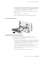
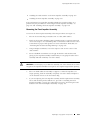
Removing the Rear Upper Impeller Assembly.. .. .. .. .. .. .. .. .. .. .. .. .. .. .. . 91
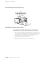
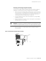
Removing the Rear Lower Impeller Assembly.. .. .. .. .. .. .. .. .. .. .. .. .. .. .. . 92
Removing the Fan Tray . .. .. .. .. .. .. .. .. .. .. .. .. .. .. .. .. .. .. .. .. .. .. .. .. .. .. .. . 93
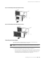
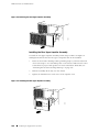
Removing the FPCs . .. .. .. .. .. .. .. .. .. .. .. .. .. .. .. .. .. .. .. .. .. .. .. .. .. .. .. .. .. . 94
Removing the Front Impeller Assembly .. .. .. .. .. .. .. .. .. .. .. .. .. .. .. .. .. .. . 96
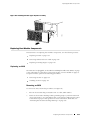
Installing the Chassis into the Rack .. .. .. .. .. .. .. .. .. .. .. .. .. .. .. .. .. .. .. .. .. .. .. . 97
Reinstalling Components into the Chassis . .. .. .. .. .. .. .. .. .. .. .. .. .. .. .. .. .. .. .. . 99
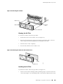
Reinstalling the Front Impeller Assembly . .. .. .. .. .. .. .. .. .. .. .. .. .. .. .. .. .. 100
Reinstalling the FPCs . .. .. .. .. .. .. .. .. .. .. .. .. .. .. .. .. .. .. .. .. .. .. .. .. .. .. .. .. 101
Reinstalling the Fan Tray . .. .. .. .. .. .. .. .. .. .. .. .. .. .. .. .. .. .. .. .. .. .. .. .. .. .. 102
Reinstalling the Rear Lower Impeller Assembly .. .. .. .. .. .. .. .. .. .. .. .. .. .. 103
Reinstalling the Rear Upper Impeller Assembly .. .. .. .. .. .. .. .. .. .. .. .. .. .. 104
Reinstalling the Routing Engines .. .. .. .. .. .. .. .. .. .. .. .. .. .. .. .. .. .. .. .. .. .. 105
Reinstalling the PCGs . .. .. .. .. .. .. .. .. .. .. .. .. .. .. .. .. .. .. .. .. .. .. .. .. .. .. .. .. 106
Reinstalling the MCSs. .. .. .. .. .. .. .. .. .. .. .. .. .. .. .. .. .. .. .. .. .. .. .. .. .. .. .. .. 107
Table of Contents
vii
M160 Internet Router Hardware Guide
Reinstalling the SFMs . .. .. .. .. .. .. .. .. .. .. .. .. .. .. .. .. .. .. .. .. .. .. .. .. .. .. .. .. 108
Reinstalling the Rear Component Cover .. .. .. .. .. .. .. .. .. .. .. .. .. .. .. .. .. .. 109
Reinstalling the Power Supplies.. .. .. .. .. .. .. .. .. .. .. .. .. .. .. .. .. .. .. .. .. .. .. 109
Chapter
9
Connecting the Router and Performing Initial Configuration ..
111
Tools and Parts Required .. .. .. .. .. .. .. .. .. .. .. .. .. .. .. .. .. .. .. .. .. .. .. .. .. .. .. .. .. 111
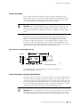
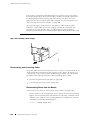
Connecting the Router to Management and Alarm Devices . .. .. .. .. .. .. .. .. .. 112
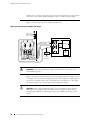
Connecting to a Network for Out-of-Band Management. .. .. .. .. .. .. .. .. .. 114
Connecting to a Management Console or Auxiliary Device . .. .. .. .. .. .. .. 114
Connecting to an External Alarm-Reporting Device . .. .. .. .. .. .. .. .. .. .. .. 115
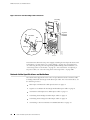
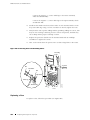
Connecting PIC Cables .. .. .. .. .. .. .. .. .. .. .. .. .. .. .. .. .. .. .. .. .. .. .. .. .. .. .. .. .. .. 115
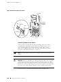
Providing Power to the Router .. .. .. .. .. .. .. .. .. .. .. .. .. .. .. .. .. .. .. .. .. .. .. .. .. .. 117
Connecting Power to the Router . .. .. .. .. .. .. .. .. .. .. .. .. .. .. .. .. .. .. .. .. .. .. 117
Powering On the Router .. .. .. .. .. .. .. .. .. .. .. .. .. .. .. .. .. .. .. .. .. .. .. .. .. .. .. 119
Configuring the JUNOS Internet Software . .. .. .. .. .. .. .. .. .. .. .. .. .. .. .. .. .. .. .. 121
Part 3
viii
Hardware Maintenance, Replacement, and Troubleshooting
Procedures
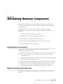
Chapter 10
Maintaining Hardware Components ..
127
Routine Maintenance Procedures .. .. .. .. .. .. .. .. .. .. .. .. .. .. .. .. .. .. .. .. .. .. .. ..127
Maintaining Cooling System Components. .. .. .. .. .. .. .. .. .. .. .. .. .. .. .. .. .. .. ..127
Maintaining the Air Filter. .. .. .. .. .. .. .. .. .. .. .. .. .. .. .. .. .. .. .. .. .. .. .. .. .. ..128
Removing the Air Filter .. .. .. .. .. .. .. .. .. .. .. .. .. .. .. .. .. .. .. .. .. .. .. .. ..128
Cleaning the Air Filter . .. .. .. .. .. .. .. .. .. .. .. .. .. .. .. .. .. .. .. .. .. .. .. .. ..129
Installing the Air Filter . .. .. .. .. .. .. .. .. .. .. .. .. .. .. .. .. .. .. .. .. .. .. .. .. ..129
Maintaining the Fan Tray and Impellers .. .. .. .. .. .. .. .. .. .. .. .. .. .. .. .. .. ..130
Maintaining Host Module Components .. .. .. .. .. .. .. .. .. .. .. .. .. .. .. .. .. .. .. .. .. 131
Maintaining Packet Forwarding Engine Components . .. .. .. .. .. .. .. .. .. .. .. .. ..132
Maintaining FPCs . .. .. .. .. .. .. .. .. .. .. .. .. .. .. .. .. .. .. .. .. .. .. .. .. .. .. .. .. .. ..133
Maintaining PICs and PIC Cables .. .. .. .. .. .. .. .. .. .. .. .. .. .. .. .. .. .. .. .. .. ..134
Maintaining the PCGs. .. .. .. .. .. .. .. .. .. .. .. .. .. .. .. .. .. .. .. .. .. .. .. .. .. .. .. ..135
Maintaining SFMs . .. .. .. .. .. .. .. .. .. .. .. .. .. .. .. .. .. .. .. .. .. .. .. .. .. .. .. .. .. ..136
Maintaining Power Supplies .. .. .. .. .. .. .. .. .. .. .. .. .. .. .. .. .. .. .. .. .. .. .. .. .. .. ..137
Chapter 11
Replacing Hardware Components. .
139
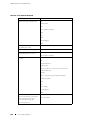
Tools and Parts Required .. .. .. .. .. .. .. .. .. .. .. .. .. .. .. .. .. .. .. .. .. .. .. .. .. .. .. .. ..139
Replacing the CIP and Routing Engine Interface Port Cables .. .. .. .. .. .. .. .. .. 141
Removing the CIP. .. .. .. .. .. .. .. .. .. .. .. .. .. .. .. .. .. .. .. .. .. .. .. .. .. .. .. .. .. .. 141
Installing the CIP .. .. .. .. .. .. .. .. .. .. .. .. .. .. .. .. .. .. .. .. .. .. .. .. .. .. .. .. .. .. ..143
Replacing Connections to Routing Engine Interface Ports . .. .. .. .. .. .. .. ..145
Replacing the Management Ethernet Cable.. .. .. .. .. .. .. .. .. .. .. .. .. ..146
Replacing the Console or Auxiliary Cable .. .. .. .. .. .. .. .. .. .. .. .. .. .. ..146
Replace Alarm Relay Wires.. .. .. .. .. .. .. .. .. .. .. .. .. .. .. .. .. .. .. .. .. .. ..147
Replacing Cooling System Components . .. .. .. .. .. .. .. .. .. .. .. .. .. .. .. .. .. .. .. ..148
Replacing the Fan Tray . .. .. .. .. .. .. .. .. .. .. .. .. .. .. .. .. .. .. .. .. .. .. .. .. .. .. ..148
Table of Contents
Table of Contents
Removing the Fan Tray .. .. .. .. .. .. .. .. .. .. .. .. .. .. .. .. .. .. .. .. .. .. .. .. ..148
Installing the Fan Tray . .. .. .. .. .. .. .. .. .. .. .. .. .. .. .. .. .. .. .. .. .. .. .. .. ..149
Replacing the Front Impeller Assembly . .. .. .. .. .. .. .. .. .. .. .. .. .. .. .. .. .. ..150
Removing the Front Impeller Assembly.. .. .. .. .. .. .. .. .. .. .. .. .. .. .. .. 151
Removing the Craft Interface from the Front Impeller Assembly .. ..152
Installing the Craft Interface on the Front Impeller Assembly.. .. .. ..153
Installing the Front Impeller Assembly . .. .. .. .. .. .. .. .. .. .. .. .. .. .. .. ..154
Replacing the Rear Lower Impeller Assembly .. .. .. .. .. .. .. .. .. .. .. .. .. .. ..154
Removing the Rear Lower Impeller Assembly . .. .. .. .. .. .. .. .. .. .. .. ..155
Installing the Rear Lower Impeller Assembly .. .. .. .. .. .. .. .. .. .. .. .. ..155
Replacing the Rear Upper Impeller Assembly .. .. .. .. .. .. .. .. .. .. .. .. .. .. ..156
Removing the Rear Upper Impeller Assembly . .. .. .. .. .. .. .. .. .. .. .. ..157
Installing the Rear Upper Impeller Assembly .. .. .. .. .. .. .. .. .. .. .. .. ..158
Replacing Host Module Components .. .. .. .. .. .. .. .. .. .. .. .. .. .. .. .. .. .. .. .. .. ..159
Replacing an MCS. .. .. .. .. .. .. .. .. .. .. .. .. .. .. .. .. .. .. .. .. .. .. .. .. .. .. .. .. .. ..159
Removing an MCS.. .. .. .. .. .. .. .. .. .. .. .. .. .. .. .. .. .. .. .. .. .. .. .. .. .. .. ..159
Installing an MCS. .. .. .. .. .. .. .. .. .. .. .. .. .. .. .. .. .. .. .. .. .. .. .. .. .. .. .. .. 161
Removing and Insert the PC Card . .. .. .. .. .. .. .. .. .. .. .. .. .. .. .. .. .. .. .. .. ..163
Removing the PC Card. .. .. .. .. .. .. .. .. .. .. .. .. .. .. .. .. .. .. .. .. .. .. .. .. ..163
Insert the PC Card.. .. .. .. .. .. .. .. .. .. .. .. .. .. .. .. .. .. .. .. .. .. .. .. .. .. .. ..164
Replacing a Routing Engine .. .. .. .. .. .. .. .. .. .. .. .. .. .. .. .. .. .. .. .. .. .. .. .. ..165
Removing a Routing Engine. .. .. .. .. .. .. .. .. .. .. .. .. .. .. .. .. .. .. .. .. .. ..165
Installing a Routing Engine .. .. .. .. .. .. .. .. .. .. .. .. .. .. .. .. .. .. .. .. .. .. ..168
Replacing Packet Forwarding Engine Components . .. .. .. .. .. .. .. .. .. .. .. .. .. ..169
Replacing an FPC . .. .. .. .. .. .. .. .. .. .. .. .. .. .. .. .. .. .. .. .. .. .. .. .. .. .. .. .. .. ..169
Removing an FPC .. .. .. .. .. .. .. .. .. .. .. .. .. .. .. .. .. .. .. .. .. .. .. .. .. .. .. ..170
Installing an FPC . .. .. .. .. .. .. .. .. .. .. .. .. .. .. .. .. .. .. .. .. .. .. .. .. .. .. .. ..172
Replacing a PCG. .. .. .. .. .. .. .. .. .. .. .. .. .. .. .. .. .. .. .. .. .. .. .. .. .. .. .. .. .. .. ..176
Removing a PCG . .. .. .. .. .. .. .. .. .. .. .. .. .. .. .. .. .. .. .. .. .. .. .. .. .. .. .. ..176
Installing a PCG. .. .. .. .. .. .. .. .. .. .. .. .. .. .. .. .. .. .. .. .. .. .. .. .. .. .. .. .. ..178
Replacing a PIC . .. .. .. .. .. .. .. .. .. .. .. .. .. .. .. .. .. .. .. .. .. .. .. .. .. .. .. .. .. .. ..179
Removing a PIC .. .. .. .. .. .. .. .. .. .. .. .. .. .. .. .. .. .. .. .. .. .. .. .. .. .. .. .. ..179
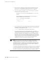
Installing a PIC . .. .. .. .. .. .. .. .. .. .. .. .. .. .. .. .. .. .. .. .. .. .. .. .. .. .. .. .. .. 181
Replace PIC Cables . .. .. .. .. .. .. .. .. .. .. .. .. .. .. .. .. .. .. .. .. .. .. .. .. .. .. .. .. ..185
Removing a PIC Cable . .. .. .. .. .. .. .. .. .. .. .. .. .. .. .. .. .. .. .. .. .. .. .. .. ..185
Installing a PIC Cable .. .. .. .. .. .. .. .. .. .. .. .. .. .. .. .. .. .. .. .. .. .. .. .. .. ..186
Replacing an SFM . .. .. .. .. .. .. .. .. .. .. .. .. .. .. .. .. .. .. .. .. .. .. .. .. .. .. .. .. .. ..188
Removing an SFM.. .. .. .. .. .. .. .. .. .. .. .. .. .. .. .. .. .. .. .. .. .. .. .. .. .. .. ..188
Installing an SFM . .. .. .. .. .. .. .. .. .. .. .. .. .. .. .. .. .. .. .. .. .. .. .. .. .. .. .. ..189
Replace an SFP.. .. .. .. .. .. .. .. .. .. .. .. .. .. .. .. .. .. .. .. .. .. .. .. .. .. .. .. .. .. .. ..190
Removing an SFP .. .. .. .. .. .. .. .. .. .. .. .. .. .. .. .. .. .. .. .. .. .. .. .. .. .. .. ..190
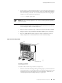
Installing an SFP.. .. .. .. .. .. .. .. .. .. .. .. .. .. .. .. .. .. .. .. .. .. .. .. .. .. .. .. .. 191
Replacing Power System Components . .. .. .. .. .. .. .. .. .. .. .. .. .. .. .. .. .. .. .. .. ..193
Replacing the Circuit Breaker Box . .. .. .. .. .. .. .. .. .. .. .. .. .. .. .. .. .. .. .. .. ..193
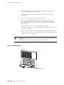
Removing the Circuit Breaker Box .. .. .. .. .. .. .. .. .. .. .. .. .. .. .. .. .. .. ..193
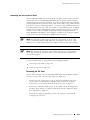
Installing the Circuit Breaker Box . .. .. .. .. .. .. .. .. .. .. .. .. .. .. .. .. .. .. ..195
Replacing a Power Supply .. .. .. .. .. .. .. .. .. .. .. .. .. .. .. .. .. .. .. .. .. .. .. .. .. ..197
Removing a Power Supply. .. .. .. .. .. .. .. .. .. .. .. .. .. .. .. .. .. .. .. .. .. .. ..197
Installing a Power Supply .. .. .. .. .. .. .. .. .. .. .. .. .. .. .. .. .. .. .. .. .. .. .. ..199
Disconnecting and Connecting Power .. .. .. .. .. .. .. .. .. .. .. .. .. .. .. .. .. .. ..200
Disconnecting Power from the Router.. .. .. .. .. .. .. .. .. .. .. .. .. .. .. .. ..200
Connecting Power to the Router .. .. .. .. .. .. .. .. .. .. .. .. .. .. .. .. .. .. .. ..202
Replacing a Fuse .. .. .. .. .. .. .. .. .. .. .. .. .. .. .. .. .. .. .. .. .. .. .. .. .. .. .. .. .. .. ..204
Table of Contents
ix
M160 Internet Router Hardware Guide
Chapter 12
Part 4
Appendixes
Appendix A
x
Troubleshooting Hardware Components..
207
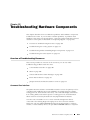
Overview of Troubleshooting Resources . .. .. .. .. .. .. .. .. .. .. .. .. .. .. .. .. .. .. .. .. 207
Command-Line Interface . .. .. .. .. .. .. .. .. .. .. .. .. .. .. .. .. .. .. .. .. .. .. .. .. .. .. 207
LEDs . .. .. .. .. .. .. .. .. .. .. .. .. .. .. .. .. .. .. .. .. .. .. .. .. .. .. .. .. .. .. .. .. .. .. .. .. ..208
LEDs on the Craft Interface.. .. .. .. .. .. .. .. .. .. .. .. .. .. .. .. .. .. .. .. .. .. ..208
LEDs on Hardware Components .. .. .. .. .. .. .. .. .. .. .. .. .. .. .. .. .. .. .. ..209
Chassis and Interface Alarm Messages.. .. .. .. .. .. .. .. .. .. .. .. .. .. .. .. .. .. ..209
Blown Fuse Indicators .. .. .. .. .. .. .. .. .. .. .. .. .. .. .. .. .. .. .. .. .. .. .. .. .. .. .. .. 211
Juniper Networks Technical Assistance Center . .. .. .. .. .. .. .. .. .. .. .. .. .. .. 212
Troubleshooting the Cooling System . .. .. .. .. .. .. .. .. .. .. .. .. .. .. .. .. .. .. .. .. .. .. 212
Troubleshooting Packet Forwarding Engine Components .. .. .. .. .. .. .. .. .. .. .. 213
Troubleshooting FPCs. .. .. .. .. .. .. .. .. .. .. .. .. .. .. .. .. .. .. .. .. .. .. .. .. .. .. .. .. 214
Troubleshooting PICs . .. .. .. .. .. .. .. .. .. .. .. .. .. .. .. .. .. .. .. .. .. .. .. .. .. .. .. .. 215
Troubleshooting the Power System. .. .. .. .. .. .. .. .. .. .. .. .. .. .. .. .. .. .. .. .. .. .. .. 215
All LEDs on Both Supplies Are Off . .. .. .. .. .. .. .. .. .. .. .. .. .. .. .. .. .. .. .. .. .. 215
All LEDs on One Supply Are Off or LED States Are not Correct. .. .. .. .. .. 216
Table of Contents
Safety and Regulatory Compliance Information. .
221
Definition of Safety Warning Levels .. .. .. .. .. .. .. .. .. .. .. .. .. .. .. .. .. .. .. .. .. .. .. 221
Safety Guidelines and Warnings .. .. .. .. .. .. .. .. .. .. .. .. .. .. .. .. .. .. .. .. .. .. .. .. ..222
General Safety Guidelines and Warnings.. .. .. .. .. .. .. .. .. .. .. .. .. .. .. .. .. ..224
Qualified Personnel Warning .. .. .. .. .. .. .. .. .. .. .. .. .. .. .. .. .. .. .. .. .. ..225
Restricted Access Area Warning .. .. .. .. .. .. .. .. .. .. .. .. .. .. .. .. .. .. .. ..225
Preventing Electrostatic Discharge Damage . .. .. .. .. .. .. .. .. .. .. .. .. ..226
Electrical Safety Guidelines and Warnings .. .. .. .. .. .. .. .. .. .. .. .. .. .. .. .. ..227
General Electrical Safety Guidelines .. .. .. .. .. .. .. .. .. .. .. .. .. .. .. .. .. ..229
DC Power Electrical Safety Guidelines.. .. .. .. .. .. .. .. .. .. .. .. .. .. .. .. ..229
Copper Conductors Warning . .. .. .. .. .. .. .. .. .. .. .. .. .. .. .. .. .. .. .. .. ..230
DC Power Disconnection Warning .. .. .. .. .. .. .. .. .. .. .. .. .. .. .. .. .. .. .. 231
DC Power Grounding Requirements and Warning. .. .. .. .. .. .. .. .. .. ..232
DC Power Wiring Sequence Warning . .. .. .. .. .. .. .. .. .. .. .. .. .. .. .. .. ..233
DC Power Wiring Terminations Warning. .. .. .. .. .. .. .. .. .. .. .. .. .. .. ..234
Grounded Equipment Warning.. .. .. .. .. .. .. .. .. .. .. .. .. .. .. .. .. .. .. .. ..235
In Case of Electrical Accident . .. .. .. .. .. .. .. .. .. .. .. .. .. .. .. .. .. .. .. .. ..236
Midplane Energy Hazard Warning .. .. .. .. .. .. .. .. .. .. .. .. .. .. .. .. .. .. ..236
Multiple Power Supplies Disconnection Warning .. .. .. .. .. .. .. .. .. .. ..236
Power Disconnection Warning .. .. .. .. .. .. .. .. .. .. .. .. .. .. .. .. .. .. .. .. ..237
TN Power Warning . .. .. .. .. .. .. .. .. .. .. .. .. .. .. .. .. .. .. .. .. .. .. .. .. .. .. ..238
Installation Safety Guidelines and Warnings .. .. .. .. .. .. .. .. .. .. .. .. .. .. .. ..239
Chassis Lifting Guidelines . .. .. .. .. .. .. .. .. .. .. .. .. .. .. .. .. .. .. .. .. .. .. ..239
Installation Instructions Warning . .. .. .. .. .. .. .. .. .. .. .. .. .. .. .. .. .. .. ..239
Rack-Mounting Requirements and Warnings .. .. .. .. .. .. .. .. .. .. .. .. ..240
Ramp Warning . .. .. .. .. .. .. .. .. .. .. .. .. .. .. .. .. .. .. .. .. .. .. .. .. .. .. .. .. ..244
Laser and LED Safety Guidelines and Warnings .. .. .. .. .. .. .. .. .. .. .. .. .. ..244
General Laser Safety Guidelines. .. .. .. .. .. .. .. .. .. .. .. .. .. .. .. .. .. .. .. ..245
Class 1 Laser Product Warning .. .. .. .. .. .. .. .. .. .. .. .. .. .. .. .. .. .. .. .. ..245
Class 1 LED Product Warning . .. .. .. .. .. .. .. .. .. .. .. .. .. .. .. .. .. .. .. .. ..245
Table of Contents
Laser Beam Warning . .. .. .. .. .. .. .. .. .. .. .. .. .. .. .. .. .. .. .. .. .. .. .. .. .. ..246
Radiation From Open Port Apertures Warning .. .. .. .. .. .. .. .. .. .. .. ..247
Maintenance and Operational Safety Guidelines and Warnings .. .. .. .. ..247
Battery Handling Warning . .. .. .. .. .. .. .. .. .. .. .. .. .. .. .. .. .. .. .. .. .. .. ..248
Jewelry Removal Warning . .. .. .. .. .. .. .. .. .. .. .. .. .. .. .. .. .. .. .. .. .. .. ..249
Lightning Activity Warning .. .. .. .. .. .. .. .. .. .. .. .. .. .. .. .. .. .. .. .. .. .. ..250
Operating Temperature Warning.. .. .. .. .. .. .. .. .. .. .. .. .. .. .. .. .. .. .. .. 251
Product Disposal Warning . .. .. .. .. .. .. .. .. .. .. .. .. .. .. .. .. .. .. .. .. .. .. ..252
Agency Approvals.. .. .. .. .. .. .. .. .. .. .. .. .. .. .. .. .. .. .. .. .. .. .. .. .. .. .. .. .. .. .. .. ..253
Compliance Statements for EMC Requirements .. .. .. .. .. .. .. .. .. .. .. .. .. .. .. ..254
Canada. .. .. .. .. .. .. .. .. .. .. .. .. .. .. .. .. .. .. .. .. .. .. .. .. .. .. .. .. .. .. .. .. .. .. .. ..254
European Community .. .. .. .. .. .. .. .. .. .. .. .. .. .. .. .. .. .. .. .. .. .. .. .. .. .. .. ..254
Japan . .. .. .. .. .. .. .. .. .. .. .. .. .. .. .. .. .. .. .. .. .. .. .. .. .. .. .. .. .. .. .. .. .. .. .. .. ..254
United States .. .. .. .. .. .. .. .. .. .. .. .. .. .. .. .. .. .. .. .. .. .. .. .. .. .. .. .. .. .. .. .. ..254
Part 5
Appendix B
Contacting Customer Support and Returning Hardware . .
255
Locating Component Serial Numbers .. .. .. .. .. .. .. .. .. .. .. .. .. .. .. .. .. .. .. .. .. ..255
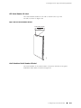
CIP Serial Number ID Label .. .. .. .. .. .. .. .. .. .. .. .. .. .. .. .. .. .. .. .. .. .. .. .. ..257
Craft Interface Serial Number ID Label.. .. .. .. .. .. .. .. .. .. .. .. .. .. .. .. .. .. ..257
DC Power Supply Serial Number ID Label .. .. .. .. .. .. .. .. .. .. .. .. .. .. .. .. ..258
FPC Serial Number ID Label . .. .. .. .. .. .. .. .. .. .. .. .. .. .. .. .. .. .. .. .. .. .. .. ..259
MCS Serial Number ID Label . .. .. .. .. .. .. .. .. .. .. .. .. .. .. .. .. .. .. .. .. .. .. .. ..259
PCG Serial Number ID Label . .. .. .. .. .. .. .. .. .. .. .. .. .. .. .. .. .. .. .. .. .. .. .. ..260
PIC Serial Number ID Label .. .. .. .. .. .. .. .. .. .. .. .. .. .. .. .. .. .. .. .. .. .. .. .. ..260
Routing Engine Serial Number ID Label. .. .. .. .. .. .. .. .. .. .. .. .. .. .. .. .. .. .. 261
SFM Serial Number ID Label . .. .. .. .. .. .. .. .. .. .. .. .. .. .. .. .. .. .. .. .. .. .. .. ..262
Contacting Customer Support .. .. .. .. .. .. .. .. .. .. .. .. .. .. .. .. .. .. .. .. .. .. .. .. .. ..262
Information You Might Need to Supply to JTAC. .. .. .. .. .. .. .. .. .. .. .. .. .. ..263
Return Procedure .. .. .. .. .. .. .. .. .. .. .. .. .. .. .. .. .. .. .. .. .. .. .. .. .. .. .. .. .. .. .. .. ..263
Tools and Parts Required . .. .. .. .. .. .. .. .. .. .. .. .. .. .. .. .. .. .. .. .. .. .. .. .. .. .. .. ..264
Packing the Routing Node for Shipment . .. .. .. .. .. .. .. .. .. .. .. .. .. .. .. .. .. .. .. ..265
Packing Components for Shipment .. .. .. .. .. .. .. .. .. .. .. .. .. .. .. .. .. .. .. .. .. .. ..267
Appendix C
Cable Connector Pinouts . .
269
RJ-45 Connector Pinouts for the Routing Engine ETHERNET Port. .. .. .. .. .. ..269
DB-9 Connector Pinouts for the Routing Engine AUXILIARY and CONSOLE
Ports .. .. .. .. .. .. .. .. .. .. .. .. .. .. .. .. .. .. .. .. .. .. .. .. .. .. .. .. .. .. .. .. .. .. .. .. .. .. .. ..270
RJ-48 Cable Pinouts for E1 and T1 PICs . .. .. .. .. .. .. .. .. .. .. .. .. .. .. .. .. .. .. .. ..270
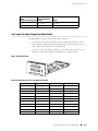
X.21 and V.35 Cable Pinouts for EIA-530 PIC . .. .. .. .. .. .. .. .. .. .. .. .. .. .. .. .. ..273
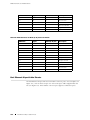
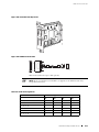
Fast Ethernet 48-port Cable Pinouts . .. .. .. .. .. .. .. .. .. .. .. .. .. .. .. .. .. .. .. .. .. ..274
Index
Index.. .. .. .. .. .. .. .. .. .. .. .. .. .. .. .. .. .. .. .. .. .. .. .. .. .. .. .. .. .. .. .. .. .. .. .. .. .. .. ..279
Table of Contents
xi
M160 Internet Router Hardware Guide
xii
Table of Contents
List of Figures
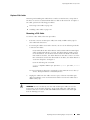
Figure 1: Front of Chassis . . . . . . . . . . . . . . . . . . . . . . . . . . . . . . . . . . . . . . . . . . . . . . . . . . . . . . . . . . . . . . . . . . . . . . . . 8
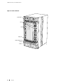
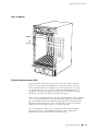
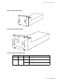
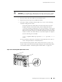
Figure 2: Rear of Chassis with Component Cover in Place . . . . . . . . . . . . . . . . . . . . . . . . . . . . . . . . . . . . . 9
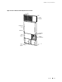
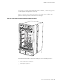
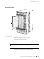
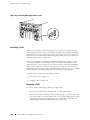
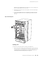
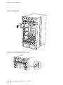
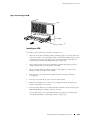
Figure 3: Rear of Chassis with Component Cover Removed . . . . . . . . . . . . . . . . . . . . . . . . . . . . . . . . . . 10
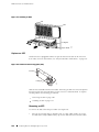
Figure 4: Midplane. . . . . . . . . . . . . . . . . . . . . . . . . . . . . . . . . . . . . . . . . . . . . . . . . . . . . . . . . . . . . . . . . . . . . . . . . . . . . . . 13
Figure 5: Front of Chassis with Four-PIC FPC Installed in Slot FPC0 . . . . . . . . . . . . . . . . . . . . . . . . . . 15
Figure 6: FPC1 and FPC2. . . . . . . . . . . . . . . . . . . . . . . . . . . . . . . . . . . . . . . . . . . . . . . . . . . . . . . . . . . . . . . . . . . . . . . . 18
Figure 7: Packet Forwarding Engine Clock Generator. . . . . . . . . . . . . . . . . . . . . . . . . . . . . . . . . . . . . . . . . . 19
Figure 8: Switching and Forwarding Module . . . . . . . . . . . . . . . . . . . . . . . . . . . . . . . . . . . . . . . . . . . . . . . . . . . 21
Figure 9: Routing Engine . . . . . . . . . . . . . . . . . . . . . . . . . . . . . . . . . . . . . . . . . . . . . . . . . . . . . . . . . . . . . . . . . . . . . . . . 25
Figure 10: Miscellaneous Control Subsystem. . . . . . . . . . . . . . . . . . . . . . . . . . . . . . . . . . . . . . . . . . . . . . . . . . . 27
Figure 11: Craft Interface . . . . . . . . . . . . . . . . . . . . . . . . . . . . . . . . . . . . . . . . . . . . . . . . . . . . . . . . . . . . . . . . . . . . . . . . 28
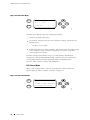
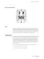
Figure 12: LCD in Idle Mode . . . . . . . . . . . . . . . . . . . . . . . . . . . . . . . . . . . . . . . . . . . . . . . . . . . . . . . . . . . . . . . . . . . . 30
Figure 13: LCD in Alarm Mode. . . . . . . . . . . . . . . . . . . . . . . . . . . . . . . . . . . . . . . . . . . . . . . . . . . . . . . . . . . . . . . . . . 30
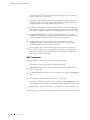
Figure 14: Connector Interface Panel. . . . . . . . . . . . . . . . . . . . . . . . . . . . . . . . . . . . . . . . . . . . . . . . . . . . . . . . . . . 33
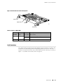
Figure 15: Routing Engine Interface Ports for Host Module 0 . . . . . . . . . . . . . . . . . . . . . . . . . . . . . . . . 34
Figure 16: Alarm Relay Contacts and BITS Input Ports . . . . . . . . . . . . . . . . . . . . . . . . . . . . . . . . . . . . . . . . 35
Figure 17: Original Power Supply . . . . . . . . . . . . . . . . . . . . . . . . . . . . . . . . . . . . . . . . . . . . . . . . . . . . . . . . . . . . . . . 37
Figure 18: Enhanced Power Supply. . . . . . . . . . . . . . . . . . . . . . . . . . . . . . . . . . . . . . . . . . . . . . . . . . . . . . . . . . . . . 37
Figure 19: Circuit Breaker Box . . . . . . . . . . . . . . . . . . . . . . . . . . . . . . . . . . . . . . . . . . . . . . . . . . . . . . . . . . . . . . . . . . 39
Figure 20: Airflow through the Chassis . . . . . . . . . . . . . . . . . . . . . . . . . . . . . . . . . . . . . . . . . . . . . . . . . . . . . . . . . 41
Figure 21: Cable Management System . . . . . . . . . . . . . . . . . . . . . . . . . . . . . . . . . . . . . . . . . . . . . . . . . . . . . . . . . 41
Figure 22: System Architecture . . . . . . . . . . . . . . . . . . . . . . . . . . . . . . . . . . . . . . . . . . . . . . . . . . . . . . . . . . . . . . . . . 51
Figure 23: Packet Forwarding Engine Components and Data Flow . . . . . . . . . . . . . . . . . . . . . . . . . . . 53
Figure 24: Routing Engine Architecture . . . . . . . . . . . . . . . . . . . . . . . . . . . . . . . . . . . . . . . . . . . . . . . . . . . . . . . . 54
Figure 25: Control Packet Handling for Routing and Forwarding Table Updates . . . . . . . . . . . . . 55
Figure 26: Typical Center-Mount Rack. . . . . . . . . . . . . . . . . . . . . . . . . . . . . . . . . . . . . . . . . . . . . . . . . . . . . . . . . . 61
Figure 27: Chassis Dimensions and Clearance Requirements. . . . . . . . . . . . . . . . . . . . . . . . . . . . . . . . . 62
Figure 28: Power and Grounding Cable Lug . . . . . . . . . . . . . . . . . . . . . . . . . . . . . . . . . . . . . . . . . . . . . . . . . . . . 67
Figure 29: Typical Source Cabling to the Router . . . . . . . . . . . . . . . . . . . . . . . . . . . . . . . . . . . . . . . . . . . . . . . 68
Figure 30: Power and Grounding Cable Connections . . . . . . . . . . . . . . . . . . . . . . . . . . . . . . . . . . . . . . . . . . 70
Figure 31: Unpacking the Router . . . . . . . . . . . . . . . . . . . . . . . . . . . . . . . . . . . . . . . . . . . . . . . . . . . . . . . . . . . . . . . 79
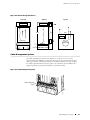
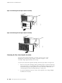
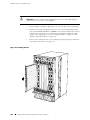
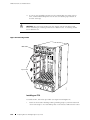
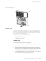
Figure 32: Removing a Power Supply . . . . . . . . . . . . . . . . . . . . . . . . . . . . . . . . . . . . . . . . . . . . . . . . . . . . . . . . . . 86
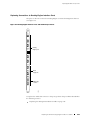
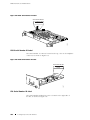
Figure 33: Removing an SFM . . . . . . . . . . . . . . . . . . . . . . . . . . . . . . . . . . . . . . . . . . . . . . . . . . . . . . . . . . . . . . . . . . . 88
Figure 34: Removing an MCS . . . . . . . . . . . . . . . . . . . . . . . . . . . . . . . . . . . . . . . . . . . . . . . . . . . . . . . . . . . . . . . . . . . 89
Figure 35: Removing a PCG . . . . . . . . . . . . . . . . . . . . . . . . . . . . . . . . . . . . . . . . . . . . . . . . . . . . . . . . . . . . . . . . . . . . . 90
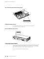
Figure 36: Removing a Routing Engine. . . . . . . . . . . . . . . . . . . . . . . . . . . . . . . . . . . . . . . . . . . . . . . . . . . . . . . . . 91
Figure 37: Removing the Rear Upper Impeller Assembly . . . . . . . . . . . . . . . . . . . . . . . . . . . . . . . . . . . . . 92
Figure 38: Removing the Rear Upper Impeller Assembly . . . . . . . . . . . . . . . . . . . . . . . . . . . . . . . . . . . . . 92
Figure 39: Removing the Rear Lower Impeller Assembly . . . . . . . . . . . . . . . . . . . . . . . . . . . . . . . . . . . . . 93
Figure 40: Removing the Fan Tray . . . . . . . . . . . . . . . . . . . . . . . . . . . . . . . . . . . . . . . . . . . . . . . . . . . . . . . . . . . . . . 94
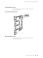
Figure 41: Removing an FPC. . . . . . . . . . . . . . . . . . . . . . . . . . . . . . . . . . . . . . . . . . . . . . . . . . . . . . . . . . . . . . . . . . . . 96
Figure 42: Removing the Front Impeller Assembly . . . . . . . . . . . . . . . . . . . . . . . . . . . . . . . . . . . . . . . . . . . . 97
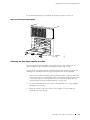
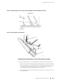
Figure 43: Attaching the Lifting Handle . . . . . . . . . . . . . . . . . . . . . . . . . . . . . . . . . . . . . . . . . . . . . . . . . . . . . . . . 98
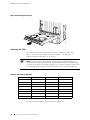
Figure 44: Installing the Chassis in a Rack . . . . . . . . . . . . . . . . . . . . . . . . . . . . . . . . . . . . . . . . . . . . . . . . . . . . . 99
Figure 45: Reinstalling the Front Impeller Assembly . . . . . . . . . . . . . . . . . . . . . . . . . . . . . . . . . . . . . . . . . 101
Figure 46: Reinstalling an FPC . . . . . . . . . . . . . . . . . . . . . . . . . . . . . . . . . . . . . . . . . . . . . . . . . . . . . . . . . . . . . . . . . 102
Figure 47: Reinstalling the Fan Tray . . . . . . . . . . . . . . . . . . . . . . . . . . . . . . . . . . . . . . . . . . . . . . . . . . . . . . . . . . . 103
Figure 48: Reinstalling the Rear Lower Impeller Assembly. . . . . . . . . . . . . . . . . . . . . . . . . . . . . . . . . . . 104
Figure 49: Reinstalling the Rear Upper Impeller Assembly. . . . . . . . . . . . . . . . . . . . . . . . . . . . . . . . . . . 105
List of Figures
xiii
M160 Internet Router Hardware Guide
Figure 50: Reinstalling the Rear Upper Impeller Assembly. . . . . . . . . . . . . . . . . . . . . . . . . . . . . . . . . . . 105
Figure 51: Reinstalling a Routing Engine . . . . . . . . . . . . . . . . . . . . . . . . . . . . . . . . . . . . . . . . . . . . . . . . . . . . . . 106
Figure 52: Reinstalling a PCG . . . . . . . . . . . . . . . . . . . . . . . . . . . . . . . . . . . . . . . . . . . . . . . . . . . . . . . . . . . . . . . . . . 107
Figure 53: Reinstalling an MCS . . . . . . . . . . . . . . . . . . . . . . . . . . . . . . . . . . . . . . . . . . . . . . . . . . . . . . . . . . . . . . . . 108
Figure 54: Reinstalling an SFM. . . . . . . . . . . . . . . . . . . . . . . . . . . . . . . . . . . . . . . . . . . . . . . . . . . . . . . . . . . . . . . . . 109
Figure 55: Reinstalling a Power Supply . . . . . . . . . . . . . . . . . . . . . . . . . . . . . . . . . . . . . . . . . . . . . . . . . . . . . . . . 110
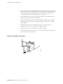
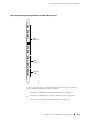
Figure 56: Routing Engine Management Ports and Alarm Relay Contacts . . . . . . . . . . . . . . . . . . 113
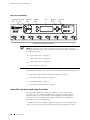
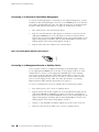
Figure 57: Routing Engine Ethernet Cable Connector . . . . . . . . . . . . . . . . . . . . . . . . . . . . . . . . . . . . . . . . 114
Figure 58: Console and Auxiliary Serial Port Connector . . . . . . . . . . . . . . . . . . . . . . . . . . . . . . . . . . . . . . 115
Figure 59: Attaching Cable to a PIC. . . . . . . . . . . . . . . . . . . . . . . . . . . . . . . . . . . . . . . . . . . . . . . . . . . . . . . . . . . . 117
Figure 60: Connecting Power and Grounding Cables . . . . . . . . . . . . . . . . . . . . . . . . . . . . . . . . . . . . . . . . . 119
Figure 61: Removing the Air Filter. . . . . . . . . . . . . . . . . . . . . . . . . . . . . . . . . . . . . . . . . . . . . . . . . . . . . . . . . . . . .129
Figure 62: Removing the Filter from the Air Filter Cover. . . . . . . . . . . . . . . . . . . . . . . . . . . . . . . . . . . . .129
Figure 63: Installing the Air Filter. . . . . . . . . . . . . . . . . . . . . . . . . . . . . . . . . . . . . . . . . . . . . . . . . . . . . . . . . . . . . .130
Figure 64: Removing the CIP . . . . . . . . . . . . . . . . . . . . . . . . . . . . . . . . . . . . . . . . . . . . . . . . . . . . . . . . . . . . . . . . . .143
Figure 65: Installing the CIP. . . . . . . . . . . . . . . . . . . . . . . . . . . . . . . . . . . . . . . . . . . . . . . . . . . . . . . . . . . . . . . . . . . .144
Figure 66: Routing Engine Interface Ports and Alarm Relay Contacts . . . . . . . . . . . . . . . . . . . . . . .145
Figure 67: Ethernet Cable Connector . . . . . . . . . . . . . . . . . . . . . . . . . . . . . . . . . . . . . . . . . . . . . . . . . . . . . . . . . .146
Figure 68: Serial Port Connector . . . . . . . . . . . . . . . . . . . . . . . . . . . . . . . . . . . . . . . . . . . . . . . . . . . . . . . . . . . . . . .147
Figure 69: Removing the Fan Tray . . . . . . . . . . . . . . . . . . . . . . . . . . . . . . . . . . . . . . . . . . . . . . . . . . . . . . . . . . . . .149
Figure 70: Installing the Fan Tray . . . . . . . . . . . . . . . . . . . . . . . . . . . . . . . . . . . . . . . . . . . . . . . . . . . . . . . . . . . . . .150
Figure 71: Removing the Front Impeller Assembly . . . . . . . . . . . . . . . . . . . . . . . . . . . . . . . . . . . . . . . . . . .152
Figure 72: Removing the Screws along the Top Front Edge of the Front Impeller
Assembly. . . . . . . . . . . . . . . . . . . . . . . . . . . . . . . . . . . . . . . . . . . . . . . . . . . . . . . . . . . . . . . . . . . . . . . . . . . . . . . . . . .153
Figure 73: Removing the Craft Interface . . . . . . . . . . . . . . . . . . . . . . . . . . . . . . . . . . . . . . . . . . . . . . . . . . . . . .153
Figure 74: Installing the Front Impeller Assembly . . . . . . . . . . . . . . . . . . . . . . . . . . . . . . . . . . . . . . . . . . . .154
Figure 75: Removing the Rear Lower Impeller Assembly . . . . . . . . . . . . . . . . . . . . . . . . . . . . . . . . . . . .155
Figure 76: Installing the Rear Lower Impeller Assembly . . . . . . . . . . . . . . . . . . . . . . . . . . . . . . . . . . . . .156
Figure 77: Removing the Rear Upper Impeller Assembly . . . . . . . . . . . . . . . . . . . . . . . . . . . . . . . . . . . .157
Figure 78: Removing the Rear Upper Impeller Assembly . . . . . . . . . . . . . . . . . . . . . . . . . . . . . . . . . . . .158
Figure 79: Installing the Rear Upper Impeller Assembly . . . . . . . . . . . . . . . . . . . . . . . . . . . . . . . . . . . . .158
Figure 80: Installing the Rear Upper Impeller Assembly . . . . . . . . . . . . . . . . . . . . . . . . . . . . . . . . . . . . .159
Figure 81: Removing an MCS . . . . . . . . . . . . . . . . . . . . . . . . . . . . . . . . . . . . . . . . . . . . . . . . . . . . . . . . . . . . . . . . . . 161
Figure 82: Installing an MCS . . . . . . . . . . . . . . . . . . . . . . . . . . . . . . . . . . . . . . . . . . . . . . . . . . . . . . . . . . . . . . . . . . .162
Figure 83: Removing the PC Card . . . . . . . . . . . . . . . . . . . . . . . . . . . . . . . . . . . . . . . . . . . . . . . . . . . . . . . . . . . . .164
Figure 84: Insert the PC Card . . . . . . . . . . . . . . . . . . . . . . . . . . . . . . . . . . . . . . . . . . . . . . . . . . . . . . . . . . . . . . . . . .165
Figure 85: Removing a Routing Engine. . . . . . . . . . . . . . . . . . . . . . . . . . . . . . . . . . . . . . . . . . . . . . . . . . . . . . . .167
Figure 86: Installing a Routing Engine. . . . . . . . . . . . . . . . . . . . . . . . . . . . . . . . . . . . . . . . . . . . . . . . . . . . . . . . .169
Figure 87: Removing an FPC. . . . . . . . . . . . . . . . . . . . . . . . . . . . . . . . . . . . . . . . . . . . . . . . . . . . . . . . . . . . . . . . . . .172
Figure 88: Installing an FPC. . . . . . . . . . . . . . . . . . . . . . . . . . . . . . . . . . . . . . . . . . . . . . . . . . . . . . . . . . . . . . . . . . . .175
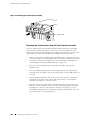
Figure 89: Connecting Fiber-Optic Cable to a PIC . . . . . . . . . . . . . . . . . . . . . . . . . . . . . . . . . . . . . . . . . . . .176
Figure 90: Removing a PCG . . . . . . . . . . . . . . . . . . . . . . . . . . . . . . . . . . . . . . . . . . . . . . . . . . . . . . . . . . . . . . . . . . . .177
Figure 91: Installing a PCG . . . . . . . . . . . . . . . . . . . . . . . . . . . . . . . . . . . . . . . . . . . . . . . . . . . . . . . . . . . . . . . . . . . . .179
Figure 92: Removing a PIC. . . . . . . . . . . . . . . . . . . . . . . . . . . . . . . . . . . . . . . . . . . . . . . . . . . . . . . . . . . . . . . . . . . . . 181
Figure 93: Installing a PIC . . . . . . . . . . . . . . . . . . . . . . . . . . . . . . . . . . . . . . . . . . . . . . . . . . . . . . . . . . . . . . . . . . . . . .184
Figure 94: Connecting Fiber-Optic Cable to a PIC . . . . . . . . . . . . . . . . . . . . . . . . . . . . . . . . . . . . . . . . . . . .184
Figure 95: Connecting Fiber-Optic Cable to a PIC . . . . . . . . . . . . . . . . . . . . . . . . . . . . . . . . . . . . . . . . . . . .187
Figure 96: Removing an SFM . . . . . . . . . . . . . . . . . . . . . . . . . . . . . . . . . . . . . . . . . . . . . . . . . . . . . . . . . . . . . . . . . .189
Figure 97: Installing an SFM . . . . . . . . . . . . . . . . . . . . . . . . . . . . . . . . . . . . . . . . . . . . . . . . . . . . . . . . . . . . . . . . . . .190
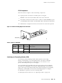
Figure 98: Small Form Factor Pluggable (SFP) . . . . . . . . . . . . . . . . . . . . . . . . . . . . . . . . . . . . . . . . . . . . . . . .190
Figure 99: Removing the Circuit Breaker Box . . . . . . . . . . . . . . . . . . . . . . . . . . . . . . . . . . . . . . . . . . . . . . . . .195
Figure 100: Installing the Circuit Breaker Box . . . . . . . . . . . . . . . . . . . . . . . . . . . . . . . . . . . . . . . . . . . . . . . . .197
Figure 101: Removing a Power Supply . . . . . . . . . . . . . . . . . . . . . . . . . . . . . . . . . . . . . . . . . . . . . . . . . . . . . . . .198
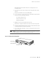
Figure 102: Rear of Power Supply Showing Midplane Connectors . . . . . . . . . . . . . . . . . . . . . . . . . . .199
xiv
List of Figures
List of Figures
Figure 103: Installing a Power Supply . . . . . . . . . . . . . . . . . . . . . . . . . . . . . . . . . . . . . . . . . . . . . . . . . . . . . . . . .200
Figure 104: Disconnecting Power Cables . . . . . . . . . . . . . . . . . . . . . . . . . . . . . . . . . . . . . . . . . . . . . . . . . . . . . .202
Figure 105: Connecting Power and Grounding Cables. . . . . . . . . . . . . . . . . . . . . . . . . . . . . . . . . . . . . . . .204
Figure 106: Fuse Locations in the Fuse Box . . . . . . . . . . . . . . . . . . . . . . . . . . . . . . . . . . . . . . . . . . . . . . . . . . .206
Figure 107: Fuse Locations in the Fuse Box . . . . . . . . . . . . . . . . . . . . . . . . . . . . . . . . . . . . . . . . . . . . . . . . . . . 211
Figure 108: Placing a Component into an Electrostatic Bag . . . . . . . . . . . . . . . . . . . . . . . . . . . . . . . . . .227
Figure 109: Serial Number ID Label . . . . . . . . . . . . . . . . . . . . . . . . . . . . . . . . . . . . . . . . . . . . . . . . . . . . . . . . . . .256
Figure 110: CIP Serial Number ID Label . . . . . . . . . . . . . . . . . . . . . . . . . . . . . . . . . . . . . . . . . . . . . . . . . . . . . . .257
Figure 111: Craft Interface Serial Number ID Label . . . . . . . . . . . . . . . . . . . . . . . . . . . . . . . . . . . . . . . . . . .258
Figure 112: DC Power Supply Serial Number ID Label. . . . . . . . . . . . . . . . . . . . . . . . . . . . . . . . . . . . . . . .258
Figure 113: FPC Serial Number ID Label . . . . . . . . . . . . . . . . . . . . . . . . . . . . . . . . . . . . . . . . . . . . . . . . . . . . . .259
Figure 114: MCS Serial Number ID Label . . . . . . . . . . . . . . . . . . . . . . . . . . . . . . . . . . . . . . . . . . . . . . . . . . . . . .260
Figure 115: PCG Serial Number ID Label . . . . . . . . . . . . . . . . . . . . . . . . . . . . . . . . . . . . . . . . . . . . . . . . . . . . .260
Figure 116: PIC Serial Number ID Label . . . . . . . . . . . . . . . . . . . . . . . . . . . . . . . . . . . . . . . . . . . . . . . . . . . . . . . 261
Figure 117: Routing Engine 333 Serial Number ID Label . . . . . . . . . . . . . . . . . . . . . . . . . . . . . . . . . . . . . 261
Figure 118: Routing Engine 600 Serial Number ID Label . . . . . . . . . . . . . . . . . . . . . . . . . . . . . . . . . . . . .262
Figure 119: SFM Serial Number ID Label . . . . . . . . . . . . . . . . . . . . . . . . . . . . . . . . . . . . . . . . . . . . . . . . . . . . .262
Figure 120: EIA-530 PIC. . . . . . . . . . . . . . . . . . . . . . . . . . . . . . . . . . . . . . . . . . . . . . . . . . . . . . . . . . . . . . . . . . . . . . . .273
Figure 121: Fast Ethernet 48-port PIC . . . . . . . . . . . . . . . . . . . . . . . . . . . . . . . . . . . . . . . . . . . . . . . . . . . . . . . . .275
Figure 122: VHDCI to RJ-21 Cable . . . . . . . . . . . . . . . . . . . . . . . . . . . . . . . . . . . . . . . . . . . . . . . . . . . . . . . . . . . . .275
List of Figures
xv
M160 Internet Router Hardware Guide
xvi
List of Figures
List of Tables
Table 1: Notice Icons . . . . . . . . . . . . . . . . . . . . . . . . . . . . . . . . . . . . . . . . . . . . . . . . . . . . . . . . . . . . . . . . . . . . . . . . . . . . xx
Table 2: Text and Syntax Conventions. . . . . . . . . . . . . . . . . . . . . . . . . . . . . . . . . . . . . . . . . . . . . . . . . . . . . . . . . . xx
Table 3: Juniper Networks Technical Documentation . . . . . . . . . . . . . . . . . . . . . . . . . . . . . . . . . . . . . . . . .xxi
Table 4: Field-Replaceable Units . . . . . . . . . . . . . . . . . . . . . . . . . . . . . . . . . . . . . . . . . . . . . . . . . . . . . . . . . . . . . . . . . 4
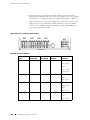
Table 5: Chassis Physical Specifications . . . . . . . . . . . . . . . . . . . . . . . . . . . . . . . . . . . . . . . . . . . . . . . . . . . . . . . . 11
Table 6: States for PCG LEDs . . . . . . . . . . . . . . . . . . . . . . . . . . . . . . . . . . . . . . . . . . . . . . . . . . . . . . . . . . . . . . . . . . . 19
Table 7: States for SFM LEDs . . . . . . . . . . . . . . . . . . . . . . . . . . . . . . . . . . . . . . . . . . . . . . . . . . . . . . . . . . . . . . . . . . . . 22
Table 8: States for MCS LEDs . . . . . . . . . . . . . . . . . . . . . . . . . . . . . . . . . . . . . . . . . . . . . . . . . . . . . . . . . . . . . . . . . . . 27
Table 9: Alarm LEDs and Alarm Cutoff/Lamp Test Button . . . . . . . . . . . . . . . . . . . . . . . . . . . . . . . . . . . . 29
Table 10: States for Host Module LEDs . . . . . . . . . . . . . . . . . . . . . . . . . . . . . . . . . . . . . . . . . . . . . . . . . . . . . . . . . 31
Table 11: States for FPC LEDs . . . . . . . . . . . . . . . . . . . . . . . . . . . . . . . . . . . . . . . . . . . . . . . . . . . . . . . . . . . . . . . . . . . 32
Table 12: States for Power Supply LEDs . . . . . . . . . . . . . . . . . . . . . . . . . . . . . . . . . . . . . . . . . . . . . . . . . . . . . . . 37
Table 13: Electrical Specifications for Power Supply . . . . . . . . . . . . . . . . . . . . . . . . . . . . . . . . . . . . . . . . . . . 38
Table 14: Spacing of Holes on Front Support Post and Center-Mounting Bracket . . . . . . . . . . . . 61
Table 15: Routing Node Environmental Specifications . . . . . . . . . . . . . . . . . . . . . . . . . . . . . . . . . . . . . . . . 63
Table 16: Component Power Requirements . . . . . . . . . . . . . . . . . . . . . . . . . . . . . . . . . . . . . . . . . . . . . . . . . . . 66
Table 17: DC Power and Grounding Cable Specifications. . . . . . . . . . . . . . . . . . . . . . . . . . . . . . . . . . . . . . 69
Table 18: Estimated Values for Factors Causing Link Loss . . . . . . . . . . . . . . . . . . . . . . . . . . . . . . . . . . . . 73
Table 19: Cable and Wire Specifications for Routing Engine Management and Alarm
Interfaces . . . . . . . . . . . . . . . . . . . . . . . . . . . . . . . . . . . . . . . . . . . . . . . . . . . . . . . . . . . . . . . . . . . . . . . . . . . . . . . . . . . 75
Table 20: Site Preparation Checklist . . . . . . . . . . . . . . . . . . . . . . . . . . . . . . . . . . . . . . . . . . . . . . . . . . . . . . . . . . . . 75
Table 21: Generic Inventory of Router Components Installed in Chassis . . . . . . . . . . . . . . . . . . . . . 79
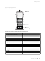
Table 22: Router Component Weights . . . . . . . . . . . . . . . . . . . . . . . . . . . . . . . . . . . . . . . . . . . . . . . . . . . . . . . . . . 83
Table 23: FPC Removal Checklist . . . . . . . . . . . . . . . . . . . . . . . . . . . . . . . . . . . . . . . . . . . . . . . . . . . . . . . . . . . . . . . 94
Table 24: Tools and Parts Required . . . . . . . . . . . . . . . . . . . . . . . . . . . . . . . . . . . . . . . . . . . . . . . . . . . . . . . . . . . .140
Table 25: Fuse Specifications. . . . . . . . . . . . . . . . . . . . . . . . . . . . . . . . . . . . . . . . . . . . . . . . . . . . . . . . . . . . . . . . . . .206
Table 26: Chassis Alarm Messages. . . . . . . . . . . . . . . . . . . . . . . . . . . . . . . . . . . . . . . . . . . . . . . . . . . . . . . . . . . . .209
Table 27: SONET/SDH Interface Alarm Messages . . . . . . . . . . . . . . . . . . . . . . . . . . . . . . . . . . . . . . . . . . . . . 210
Table 28: RJ-45 Connector Pinout. . . . . . . . . . . . . . . . . . . . . . . . . . . . . . . . . . . . . . . . . . . . . . . . . . . . . . . . . . . . . .269
Table 29: DB-9 Connector Pinout . . . . . . . . . . . . . . . . . . . . . . . . . . . . . . . . . . . . . . . . . . . . . . . . . . . . . . . . . . . . . .270
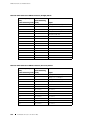
Table 30: RJ-48 Connector to RJ-48 Connector (Straight) Pinout . . . . . . . . . . . . . . . . . . . . . . . . . . . . .270
Table 31: RJ-48 Connector to RJ-48 Connector (Crossover) Pinout . . . . . . . . . . . . . . . . . . . . . . . . . . . 271
Table 32: RJ-48 Connector to DB-15 Connector (Straight) Pinout . . . . . . . . . . . . . . . . . . . . . . . . . . . .272
Table 33: RJ-48 Connector to DB-15 Connector (Crossover) Pinout . . . . . . . . . . . . . . . . . . . . . . . . . .272
Table 34: DB-25 Connector to V.35 Connector Pinout . . . . . . . . . . . . . . . . . . . . . . . . . . . . . . . . . . . . . . . .273
Table 35: DB-25 Connector to DB-15 (X.21) Connector Pinout. . . . . . . . . . . . . . . . . . . . . . . . . . . . . . .274
Table 36: RJ-21 Pin Assignments. . . . . . . . . . . . . . . . . . . . . . . . . . . . . . . . . . . . . . . . . . . . . . . . . . . . . . . . . . . . . . .275
List of Tables
xvii
M160 Internet Router Hardware Guide
xviii
List of Tables
About This Guide
Objectives on page xix
Audience on page xix
Documentation Conventions on page xix
List of Technical Publications on page xxi
Documentation Feedback on page xxiii
Requesting Support on page xxiii
Objectives
This manual describes hardware installation and basic troubleshooting procedures
for the Juniper Networks M160 Internet router. It explains how to prepare your
site for router installation, unpack and install the hardware, power on the router,
perform initial software configuration, and perform routine maintenance. After
completing the installation and basic configuration procedures covered in this
manual, refer to the JUNOS Internet software configuration guides for information
about further JUNOS software configuration.
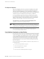
NOTE: For additional information about Juniper Networks Internet routers and the
Physical Interface Cards (PICs) they support—either corrections to or information
that might have been omitted from this guide—see the hardware release notes at
http://www.juniper.net/.
Audience
This guide is designed for network administrators who are installing and
maintaining a Juniper Networks router or preparing a site for router installation. To
use this guide, you need a broad understanding of networks in general, the Internet
in particular, networking principles, and network configuration. Any detailed
discussion of these concepts is beyond the scope of this guide.
Documentation Conventions
Table 1 defines the notice icons used in this guide.
Documentation Conventions
xix
M160 Internet Router Hardware Guide
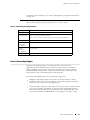
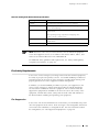
Table 1: Notice Icons
Icon
Meaning
Description
Informational note
Indicates important features or
instructions.
Caution
Indicates a situation that might result in
loss of data or hardware damage.
Warning
Alerts you to the risk of personal injury
or death.
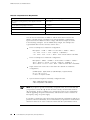
Table 2 defines the text and syntax conventions used in this guide.
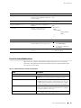
Table 2: Text and Syntax Conventions
Convention
Description
Examples
Represents text that you type.
To enter configuration mode, type the
configure command:
Bold sans serif typeface
user@host> configure
Fixed-width typeface
Italic typeface
Represents output that appears on the
terminal screen.
Introduces important new
terms.
user@host> show chassis alarms
No alarms currently active
A policy term is a named
structure that defines match
conditions and actions.
Identifies book names.
Identifies RFC and Internet draft
titles.
JUNOS System Basics
Configuration Guide
RFC 1997, BGP Communities
Attribute
Italic sans serif typeface
Sans serif typeface
Represents variables (options for which
you substitute a value) in commands or
configuration statements.
Represents names of configuration
statements, commands, files, and
directories; IP addresses; configuration
hierarchy levels; or labels on routing
platform components.
Configure the machine’s domain name:
[edit]
root@# set system domain-name
domain-name
To configure a stub area,
include the stub statement at
the [edit protocols ospf area
area-id] hierarchy level.
The console port is labeled
CONSOLE.
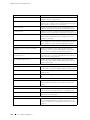
< > (angle brackets)
Enclose optional keywords or variables.
stub <default-metric metric >;
| (pipe symbol)
Indicates a choice between the mutually
exclusive keywords or variables on
either side of the symbol. The set of
choices is often enclosed in parentheses
for clarity.
broadcast | multicast
xx
Documentation Conventions
( string1 | string2 | string3 )
About This Guide
Convention
Description
Examples
# (pound sign)
Indicates a comment specified on the
same line as the configuration statement
to which it applies.
rsvp { # Required for dynamic MPLS
only
[ ] (square brackets)
Enclose a variable for which you can
substitute one or more values.
community name members [
community-ids ]
Indention and braces ( { } )
Identify a level in the configuration
hierarchy.
; (semicolon)
Identifies a leaf statement at a
configuration hierarchy level.
[edit]
routing-options {
static {
route default {
nexthop address ;
retain;
}
}
}
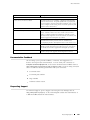
J-Web GUI Conventions
Bold typeface
Represents J-Web graphical user
interface (GUI) items you click or select.
In the Logical Interfaces box,
select All Interfaces.
To cancel the configuration,
click Cancel.
> (bold right angle bracket)
Separates levels in a hierarchy of J-Web
selections.
In the configuration editor hierarchy,
select Protocols>Ospf.
List of Technical Publications
Table 3 lists the software and hardware guides and release notes for Juniper
Networks routing platforms that use the JUNOS Internet software and describes
the contents of each book.
Table 3: Juniper Networks Technical Documentation
Book
Description
JUNOS for J-series, M-series, and T-series Routing Platforms Configuration Guides
Feature Guide
Provides a detailed explanation and configuration examples for
several of the most complex features in the JUNOS software.
System Basics
Provides an overview of the JUNOS software and describes how to
install and upgrade the software. This manual also describes how
to configure system management functions and how to configure
the chassis, including user accounts, passwords, and redundancy.
Network Interfaces and Class of Service
Provides an overview of the network interface and class-of-service
functions of the JUNOS software and describes how to configure
the network interfaces on the router.
MPLS Applications
Provides an overview of traffic engineering concepts and describes
how to configure traffic engineering protocols.
List of Technical Publications
xxi
M160 Internet Router Hardware Guide
Book
Description
Multicast Protocols
Provides an overview of multicast concepts and describes how to
configure multicast routing protocols.
Network Management
Provides an overview of network management concepts and
describes how to configure various network management features,
such as SNMP, accounting options, and cflowd.
Policy Framework
Provides an overview of policy concepts and describes how to
configure routing policy, firewall filters, and forwarding options.
Routing Protocols
Provides an overview of routing concepts and describes how to
configure routing, routing instances, and unicast routing protocols.
Services Interfaces
Provides an overview of the services interfaces functions of the
JUNOS software and describes how to configure the services
interfaces on the router.
VPNs
Provides an overview and describes how to configure Layer 2 and
Layer 3 virtual private networks (VPNs), virtual private LAN service
(VPLS), and Layer 2 circuits. Provides configuration examples.
JUNOS References
Network and Services Interfaces Command
Reference
Describes the JUNOS Internet software operational mode
commands you use to monitor and troubleshoot network and
services interfaces on Juniper Networks routing platforms.
Protocols, Class of Service, and System Basics
Command Reference
Describes the JUNOS Internet software operational mode
commands you use to monitor and troubleshoot most aspects of
Juniper Networks routing platforms.
System Log Messages Reference
Describes how to access and interpret system log messages
generated by JUNOS software modules and provides a reference
page for each message.
JUNOScript API Documentation
JUNOScript API Guide
Describes how to use the JUNOScript application programming
interface (API) to monitor and configure Juniper Networks routers.
JUNOScript API Configuration Reference
Provides reference pages for the configuration tags in the
JUNOScript API.
JUNOScript API Operational Reference
Provides reference pages for the operational tags in the JUNOScript
API.
JUNOS Comprehensive Index and Glossary
Comprehensive Index and Glossary
Provides a complete index of all JUNOS Internet software books
and the JUNOScript API Guide. Also provides a comprehensive
glossary.
Hardware Documentation
Hardware Guide
Describes how to install, maintain, and troubleshoot routers and
router components. Each platform has its own hardware guide.
PIC Guide
Describes the router Physical Interface Cards (PICs). Each router
platform has its own PIC guide.
JUNOScope Documentation
JUNOScope Software User Guide
xxii
List of Technical Publications
Describes the JUNOScope software graphical user interface (GUI),
how to install and administer the software, and how to use the
software to manage router configuration files and monitor router
operations.
About This Guide
Book
Description
J-series Services Router Documentation
J-series Services Router User Guide
Contains instructions for installing, configuring, and managing a
J-series Services Router. The guide explains how to prepare your
site for installation, unpack and install the hardware, power on the
router, configure secure routing, monitor network operations, and
perform routine maintenance.
Release Notes
JUNOS Internet Software Release Notes
Provide a summary of new features for a particular software
release. Software release notes also contain corrections and
updates to published JUNOS and JUNOScript manuals, provide
information that might have been omitted from the manuals, and
describe upgrade and downgrade procedures.
Hardware Release Notes
Describe the available documentation for the router platform
and summarize known problems with the hardware and
accompanying software. Each platform has its own release notes.
JUNOScope Software Release Notes
Contain corrections and updates to the published JUNOScope
manual, provide information that might have been omitted from
the manual, and describe upgrade and downgrade procedures.
J-series Services Router Release Notes
Briefly describe Services Router features, identify known hardware
problems, and provide upgrade and downgrade instructions
Documentation Feedback
We encourage you to provide feedback, comments, and suggestions so
that we can improve the documentation. You can send your comments to
[email protected], or fill out the documentation feedback form at
http://www.juniper.net/techpubs/docbug/docbugreport.html. If you are using e-mail, be
sure to include the following information with your comments:
Document name
Document part number
Page number
Software release version
Requesting Support
For technical support, open a support case using the Case Manager link at
http://www.juniper.net/support/ or call 1-888-314-JTAC (within the United States) or
1-408-745-9500 (outside the United States).
Requesting Support
xxiii
M160 Internet Router Hardware Guide
xxiv
Requesting Support
Part 1
Product Overview
System Overview on page 3
Hardware Component Overview on page 7
JUNOS Internet Software Overview on page 43
System Architecture Overview on page 51
Product Overview
1
2
Product Overview
Chapter 1
System Overview
This chapter provides an overview of the Juniper Networks M160 Internet router,
discussing the following topics:
System Description on page 3
Field-Replaceable Units (FRUs) on page 4
System Redundancy on page 4
Safety Requirements, Warnings, and Guidelines on page 5
System Description
The M160 Internet router is a complete routing system that provides
SONET/SDH, ATM, Ethernet, and channelized interfaces for large networks
and network applications, such as those supported by Internet service
providers (ISPs). Application-specific integrated circuits (ASICs), a definitive
part of the router design, enable the router to forward data at the high
speeds demanded by current network media.
The router accommodates up to eight Flexible PIC Concentrators (FPCs), which can
each be configured with a variety of network media types, altogether providing up to
32 OC-12/STM-4, 32 OC-48/STM-16, or eight OC-192/STM-64 ports per system. The
router height of 35 in. (89 cm) enables stacked installation of two M160 systems in
a single floor-to-ceiling rack, for increased port density per unit of floor space.
The router’s maximum aggregate throughput is 160 gigabits per second (Gbps)
simplex or 80 Gbps full duplex. The router provides very high throughput for
any combination of Physical Interface Cards (PICs) that does not exceed 3
Gbps on an FPC1 or 10 Gbps on an FPC2. A combination that exceeds these
numbers is supported, but constitutes oversubscription.
The router architecture cleanly separates control operations from packet forwarding
operations, which helps to eliminate processing and traffic bottlenecks. Control
operations in the router are performed by the Routing Engine, which runs
JUNOS Internet software to handle routing protocols, traffic engineering, policy,
policing, monitoring, and configuration management. Forwarding operations
in the router are performed by the Packet Forwarding Engine, which consists
of hardware, including ASICs, designed by Juniper Networks.
System Description
3
M160 Internet Router Hardware Guide
Field-Replaceable Units (FRUs)
Field-replaceable units (FRUs) are router components that can be replaced at
the customer site. Replacing most FRUs requires minimal router downtime.
The router uses the following types of FRUs:
Hot-removable and hot-insertable FRUs—You can remove and replace these
components without powering down the router or disrupting the routing
functions.
Hot-pluggable FRUs—You can remove and replace these components without
powering down the router, but the routing functions of the system are
interrupted when the component is removed.
Table 4 lists the FRUs for the M160 router.
Table 4: Field-Replaceable Units
Hot-Removable and
Hot-Insertable FRUs
Hot-Pluggable FRUs
Miscellaneous Control
Subsystem (MCS)
Air filter
Fan tray (located behind
the cable management
system)
Flexible PIC Concentrator
(FPC)
Physical Interface Card
(PIC)
FRUs That Require Powering
Down the Router
Circuit breaker box
Connector Interface Panel (CIP)
Packet Forwarding Engine
Clock Generator (PCG)
Routing Engine
Switching and Forwarding
Module (SFM)
Power supply
Small form factor
pluggable (SFP)
For FRU replacement instructions, see “Replacing Hardware
Components” on page 139.
System Redundancy
The router is designed so that no single point of failure can cause the entire system
to fail. The following hardware components contribute to system redundancy:
Cooling system—When the temperature inside the router is below the
acceptable maximum, the cooling system’s components function at less than
full speed. If the temperature becomes excessive—for example, because a
cooling system component is removed—the MCS automatically increases the
speed of the remaining components to reduce the temperature. The cooling
4
System Redundancy
System Overview
system can function at the higher speed indefinitely. For more information,
see Cooling System on page 39.
Host module (Routing Engine and MCS functioning together)—The router
can have one or two host modules. If two host modules are installed, one
(the master) is active and the other is in standby mode. If the master host
module (or either of its components) is removed from the chassis, the standby
host module becomes active. The Routing Engine and MCS must reside in
adjacent slots and be fully operational for the host module to function. For
more information, see Host Module on page 22.
PCG—The router has two PCGs. Both PCGs send their clock signals to the
other Packet Forwarding Engine components, along with a signal that indicates
which clock is the master. If one PCG fails, the other PCG becomes the master
system clock. For more information, see “Packet Forwarding Engine Clock
Generators (PCGs)” on page 18.
Power supply—The router has two load-sharing, fully redundant power
supplies to distribute DC power to the other components. If one power
supply fails, the second power supply can provide full power to the router’s
components indefinitely. For more information, see Power System on page 35.
SFM—The router can have up to four interconnected SFMs. If one SFM fails,
the switching and forwarding functions of the failed module are distributed
among the remaining SFMs. Total bandwidth is reduced by 1/ n , where n is
the total number of SFMs installed in the router. For example, in a system with
four SFMs, each SFM provides one-fourth of the forwarding capacity. For more
information, see “Switching and Forwarding Module (SFM)” on page 19.
In the base configuration, the router has one host module and multiple SFMs,
PCGs, power supplies, and cooling system components.
Safety Requirements, Warnings, and Guidelines
To avoid harm to yourself or the router as you install and maintain it, you need
to follow the guidelines for working with and near electrical equipment, as well
as the safety procedures for working with Internet routers. For a discussion of
how to make the installation site a safe environment, see “Preparing for Router
Installation” on page 59. For a list of safety warnings, see “Safety and Regulatory
Compliance Information” on page 221 and particularly “Electrical Safety Guidelines
and Warnings” on page 227. However, providing an exhaustive set of guidelines
for working with electrical equipment is beyond the scope of this manual.
Safety Requirements, Warnings, and Guidelines
5
M160 Internet Router Hardware Guide
6
Safety Requirements, Warnings, and Guidelines
Chapter 2
Hardware Component Overview
This chapter provides an overview of the hardware components on the M160
Internet router:
Chassis on page 7
Packet Forwarding Engine on page 11
Host Module on page 22
Craft Interface on page 27
Connector Interface Panel (CIP) on page 32
Power System on page 35
Cooling System on page 39
Cable Management System on page 41
Chassis
The router chassis is a rigid sheet metal structure that houses the other
hardware components. The chassis is 17.5 in. (44.5 cm) wide and 29 in.
(73.6 cm) deep. The chassis height of 35 in. (89 cm) enables stacked
installation of two M160 routers in a single floor-to-ceiling rack. For more
information, see Rack Requirements on page 59.
The two front support posts and center-mounting brackets (one on each
side) extend the chassis width to 19 in. (48.3 cm) and enable installation
into either a front-mount or a center-mount rack.
Figure 1, Figure 2, and Figure 3 show three views of the router chassis.
Chassis
7
M160 Internet Router Hardware Guide
Figure 1: Front of Chassis
Craft interface
R
FPCs
CIP
ESD point
Air filter
8
Chassis
1165
Cable management
system
Hardware Component Overview
Figure 2: Rear of Chassis with Component Cover in Place
Upper
impeller
Component
cover
PCG 0
Lower
impeller
Power
supplies
PCG 1
Grounding
points
Circuit
breaker box
1167
ESD point
Chassis
9
M160 Internet Router Hardware Guide
Figure 3: Rear of Chassis with Component Cover Removed
SFM 0
SFMs
MCS 0
SFM 1
MCS 0
RE 0
Routing Engines
MCS 1
RE 1
SFM 2
PCG 1
PCGs
SFM 3
1166
SFMs
PCG 0
MCS 1
The chassis includes the following electrical safety components:
Two electrostatic discharge (ESD) points (banana plug receptacles), one front
and one rear, as shown in Figure 1 and Figure 2
Two internally threaded grounding points, as shown in Figure 2
WARNING: Before removing or installing components of a functioning router, attach
an ESD strap to an ESD point and place the other end of the strap around your bare
wrist. Failure to use an ESD strap could result in damage to the router.
The router must be connected to earth ground during normal operation.
10
Chassis
Hardware Component Overview
For further safety information, see “Safety and Regulatory Compliance Information”
on page 221.
Table 5 summarizes physical specifications for the router chassis.
Table 5: Chassis Physical Specifications
Description
Value
Chassis height
35 in. (89 cm)
Chassis width
17.5 in. (44.5 cm) for sides of chassis
19 in. (48.3 cm) with front support posts and center-mounting brackets
Chassis depth
29 in. (73.6 cm)
Weight,
maximum
configuration
370.5 lb (168 kg)
Weight,
minimum
configuration
190 lb (86 kg)
Thermal output
9400 BTU/hour
Packet Forwarding Engine
The Packet Forwarding Engine is a multicomponent system that uses
application-specific integrated circuits (ASICs) to perform Layer 2 and Layer 3
packet switching, route lookups, and packet forwarding. The ASICs include the
Distributed Buffer Manager ASIC, Internet Processor II ASIC, I/O Manager ASIC,
Packet Director ASIC, and media-specific controller ASICs.
The Packet Forwarding Engine has the following components:
Midplane—Physically separates front and rear cavities inside the chassis,
distributes power from the power supplies, and transfers packets and signals
between router components, which plug into it.
Physical Interface Card (PIC)—Physically connects the router to network media
such as OC-12/STM-4, OC-48/STM-16, Ethernet, and channelized interfaces.
PICs are housed in Flexible PIC Concentrators (FPCs). (Quad-wide PICs, such
as the OC-192/STM-64 SONET/SDH PIC, are exceptions. Such PICs occupy
Packet Forwarding Engine
11
M160 Internet Router Hardware Guide
an entire FPC slot in the chassis and insert directly into the slot rather than
into an FPC card carrier.)
Flexible PIC Concentrator (FPC)—Processes incoming and outgoing packets.
Up to eight FPCs plug into the midplane from the front of the chassis. Each
FPC accommodates up to four PICs.
Packet Forwarding Engine Clock Generator (PCG)—Sends clock signals to
the other Packet Forwarding Engine components. Two PCGs plug into the
midplane from the rear of the chassis.
Switching and Forwarding Module (SFM)—Performs route lookup, filtering, and
switching. Up to four SFMs plug into the midplane from the rear of the chassis.
For information about Packet Forwarding Engine components, see the following
sections:
Midplane on page 12
Physical Interface Cards (PICs) on page 13
Flexible PIC Concentrators (FPCs) on page 14
Packet Forwarding Engine Clock Generators (PCGs) on page 18
Switching and Forwarding Module (SFM) on page 19
Midplane
The midplane is a panel located in the center of the chassis, running from side
to side and forming the rear of the FPC card cage (see Figure 4). All router
components other than PICs plug directly into the midplane. The midplane contains
an EEPROM that stores the serial number and revision level of the midplane.
The midplane performs the following functions:
Transfer of packets—The midplane accepts an incoming packet after it is
processed by an FPC, and transmits it to an SFM. The SFM performs switching
and forwarding functions and transfers outgoing packets back across the
midplane to the FPCs for transmission to the network.
Power distribution—The midplane distributes power to all router components
from the power supplies attached to it.
Signal connectivity—The midplane transports the signals exchanged by
system components for monitoring and control purposes.
12
Packet Forwarding Engine
Hardware Component Overview
Figure 4: Midplane
R
Midplane
1171
FPC
card cage
Physical Interface Cards (PICs)
Physical Interface Cards (PICs) physically connect the router to network
media. They are housed in Flexible PIC Concentrators (FPCs); for more
information about FPCs, see “Flexible PIC Concentrators (FPCs)” on page
14. (Quad-wide PICs, such as the OC-192/STM-64 SONET/SDH PIC, are
exceptions. Such PICs occupy an entire FPC slot in the chassis and insert
directly into the slot rather than into an FPC card carrier.)
PICs receive incoming packets from the network and transmit outgoing packets
to the network, performing framing and line-speed signaling for their media
type as required. PICs also encapsulate outgoing packets received from the
FPCs before transmitting them. The controller ASIC on each PIC performs
additional control functions specific to the PIC media type.
The router supports various PICs, including ATM, Channelized, Gigabit
Ethernet, IP Services, and SONET/SDH interfaces. For complete PIC
specifications, see the M160 Internet Router PIC Guide.
Packet Forwarding Engine
13
M160 Internet Router Hardware Guide
Some PICs, such as selected Gigabit Ethernet PICs, accept small form factor
pluggables (SFPs), which are fiber-optic transceivers that can be removed from
the PIC. Various SFPs have different reach characteristics. You can mix them in
a single PIC and change the combination dynamically. SFPs are hot-removable
and hot-insertable, as described in Field-Replaceable Units (FRUs) on page 4. For
SFP replacement instructions, see “Replace an SFP” on page 190. For information
about PICs that use SFPs, see the M160 Internet Router PIC Guide.
You can install up to four PICs in an FPC. The number of ports on a PIC
depends on the type of PIC. PICs are hot-removable and hot-insertable, as
described in Field-Replaceable Units (FRUs) on page 4. For PIC replacement
instructions, see “Replacing a PIC” on page 179.
PIC Components
Most PICs supported on the M160 router have the following components. For
complete specifications, see the M160 Internet Router PIC Guide. For information
about pinouts for PIC cable connectors, see “Cable Connector Pinouts” on page 269.
One or more cable connector ports—Accept a network media connector.
LEDs—Indicate PIC and port status. Most PICs have an LED labeled STATUS on
the PIC faceplate. Some PICs have additional LEDs, often one per port. The
meaning of the LED states differs for various PICs. For more information, see
the M160 Internet Router PIC Guide.
Offline button—Prepares the PIC for removal from the FPC when pressed. For
the PICs that install on an FPC1, the offline button for each PIC is next to it on
the FPC card carrier. For the PICs that install on an FPC2, the offline button is
on the PIC faceplate. See Figure 6.
Flexible PIC Concentrators (FPCs)
Flexible PIC Concentrators (FPCs) house the PICs that connect the router to network
media (for information about PICs, see “Physical Interface Cards (PICs)” on page
13). The main function of an FPC is to connect the PICs installed in it to the other
router components. An I/O Manager ASIC on the FPC divides each incoming data
packet into 64-byte cells and passes the cells through the midplane to the SFM,
where another ASIC decides how to distribute them among the memory buffers
located on and shared by all installed FPCs. After the SFM decides how to forward a
packet, an I/O Manager ASIC on the FPC reassembles the corresponding data cells
back into network-packet form and passes the packet to the appropriate PIC for
transmission to the network. For more information, see “Data Flow through the
Packet Forwarding Engine” on page 52.
Up to eight FPCs install vertically into the midplane from the front of the
chassis. The FPC slots are numbered from FPC0 to FPC7, left to right. Each FPC
accommodates up to four PICs. The PIC slots in each FPC are numbered from
0 (zero) through 3, top to bottom. An FPC can be installed into any FPC slot,
regardless of the PICs it contains, and any combination of slots can be used. If a
14
Packet Forwarding Engine
Hardware Component Overview
slot is empty, you must install a blank FPC panel to shield it, so that cooling air can
circulate properly throughout the card cage.
Figure 5, which shows a chassis with an FPC in slot FPC0, omits the blank FPC
panels to show the position of the FPC in the card cage.
Figure 5: Front of Chassis with Four-PIC FPC Installed in Slot FPC0
1189
R
For information about FPC components and types, see the following sections:
FPC Components on page 16
FPC Types on page 17
Packet Forwarding Engine
15
M160 Internet Router Hardware Guide
FPC Components
An FPC has the following components:
FPC card carrier—Houses the ASICs, connectors, and processor subsystem.
Four I/O Manager ASICs—Parse Layer 2 and Layer 3 data and perform
encapsulation and segmentation. The I/O Manager ASICs divide incoming
packets into 64-byte data cells for easier processing, and reassemble the cells
for each packet after the forwarding decision is made for it. Enhanced FPCs
have I/O Manager ASICs capable of enhanced quality of service.
Two Packet Director ASICs—Transfer packets between the PICs and the I/O
Manager ASICs: one directs incoming packets from the PICs to the I/O
Manager ASICs, while the second directs outgoing packets from the I/O
Manager ASICs to the PICs.
Eight identical synchronous DRAM (SDRAM) dual inline memory modules
(DIMMs)—Form the memory pool shared with the other FPCs installed
in the router.
Parity-protected synchronous SRAM (SSRAM)—Stores data structures used
by the I/O Manager ASICs.
Processor subsystem—Manages packet handling in the FPC and
communication with the SFM. It is a PowerPC 603e-based CPU with
parity-protected DRAM.
EEPROM—Stores the serial number and revision level of the FPC.
Two LEDs—Indicate FPC status. The LED labeled OK is green and the one
labeled FAIL is red. The LEDs for each FPC are located on the router craft
interface. For more information, see “FPC LEDs and Offline Button” on
page 31.
Offline button—Prepares the FPC for removal from the router when pressed.
Like the LEDs, an offline button is located on the craft interface. For more
information, see “FPC LEDs and Offline Button” on page 31.
Four PIC offline buttons (on FPC1 only)—Prepare each corresponding PIC
for removal from the FPC.
Ejector levers—Control the locking system that secures the FPC in the card
cage.
NOTE: For specific information about FPC components (for example, the amount of
memory available), issue the show chassis fpc command.
16
Packet Forwarding Engine
Hardware Component Overview
FPC Types
The router supports two types of FPC, shown in Figure 6:
FPC1 (standard or enhanced)—Supports PICs including single-port
OC-12/STM-4 and Gigabit Ethernet.
FPC2 (standard or enhanced)—Supports higher-speed PICs including
OC-48/STM-16 and Tunnel services.
You can install any combination of FPC types together on the router.
FPCs are hot-removable and hot-insertable, as described in Field-Replaceable Units
(FRUs) on page 4. When you remove or install an FPC, packet forwarding halts
for about 200 ms while the Packet Forwarding Engine adjusts to the change in
the amount of memory available in the pool located on and shared by all FPCs.
When you install an FPC into a functioning router, the Routing Engine downloads
the FPC software, the FPC runs its diagnostics, and the PICs housed on the FPC
are enabled. Forwarding continues uninterrupted during this process. For FPC
replacement instructions, see “Replacing an FPC” on page 169.
Enhanced FPCs have I/O Manager ASICs capable of enhanced quality of
service, and 2 MB of SSRAM. Enhanced FPCs can be identified through
the CLI, or by a sticker on the faceplate.
The PICs that install on both types of FPC are also hot-removable and hot-insertable.
For more information, see “Physical Interface Cards (PICs)” on page 13.
Packet Forwarding Engine
17
M160 Internet Router Hardware Guide
Figure 6: FPC1 and FPC2
FPC 2
FPC 1
Ejector lever
Ejector lever
Offline buttons
(on PICs)
1187
Offline buttons
(on FPC)
Ejector lever
Ejector lever
Packet Forwarding Engine Clock Generators (PCGs)
The router has two Packet Forwarding Engine Clock Generators (PCGs) installed
in the slots at the rear of the chassis that are labeled PCG 0 and PCG 1, as shown
in Figure 3. The PCGs generate a 125-MHz clock signal used to gate packet
processing. During startup, the active Routing Engine determines which PCG is
master and which is backup, and the MCS relays the decision to the PCGs and to
the modules and ASICs in the Packet Forwarding Engine that use the clock signal.
The modules and ASICs then use only the signal from the master source.
PCGs are hot-pluggable, as described in Field-Replaceable Units (FRUs) on page 4.
Removal or failure of the backup PCG does not affect router function. When the
master PCG fails or is removed from the chassis, however, the Packet Forwarding
Engine resets so that the components start using the signal from the other PCG
(which becomes the master). Packet forwarding halts while there is no clock signal,
because the Packet Forwarding Engine does not accept incoming packets. For
PCG replacement instructions, see “Replacing a PCG” on page 176.
18
Packet Forwarding Engine
Hardware Component Overview
PCG Components
Each PCG (shown in Figure 7) has the following components:
Signal generator—Provides a 125-MHz system clock signal.
EEPROM—Stores the serial number and revision level of the PCG.
Three LEDs—Indicate PCG status. There is a blue one labeled MASTER, a green
one labeled OK, and an amber one labeled FAIL. Table 6 describes the LED states.
Offline button—Prepares the PCG for removal from the router when pressed.
Offline button
1181
Figure 7: Packet Forwarding Engine Clock Generator
LEDs
Table 6: States for PCG LEDs
Label
Color
State
Description
MASTER
Blue
On steadily
PCG is master.
OK
Green
On steadily
PCG is functioning normally.
Blinking
PCG is starting up.
On steadily
PCG has failed.
FAIL
Amber
Switching and Forwarding Module (SFM)
The Switching and Forwarding Module (SFM) performs route lookup,
filtering, and switching on incoming data packets, then directs outbound
packets to the appropriate FPC for transmission to the network. It can
process 40 million packets per second (Mpps).
Up to four SFMs can be installed in the router, processing a total of 160 Mpps.
The SFMs are hot-pluggable, as described in Field-Replaceable Units (FRUs) on
page 4. Removing or inserting an SFM causes a brief interruption in forwarding
performance (about 500 ms) as the Packet Forwarding Engine reconfigures
the distribution of packets across the remaining SFMs.
For SFM replacement instructions, see “Replacing an SFM” on page 188.
Packet Forwarding Engine
19
M160 Internet Router Hardware Guide
The SFM communicates with the Routing Engine using a dedicated 100-Mbps Fast
Ethernet link that transfers routing table data from the Routing Engine to the
forwarding table in the Internet Processor II ASIC. The link is also used to transfer
from the SFM to the Routing Engine routing link-state updates and other packets
destined for the router that have been received through the router interfaces.
The ASICs and other components on the SFM provide the following functions:
Route lookups—The Internet Processor II ASIC on each SFM performs route
lookups using the forwarding table stored in SSRAM.
Management of shared memory on the FPCs—One Distributed Buffer Manager
ASIC receives the 64-byte data cells into which the I/O Manager ASICs on each
FPC divide incoming packets, and uniformly allocates them throughout the
shared memory buffers located on the FPCs.
Transfer of outgoing data packets—The second Distributed Buffer Manager
ASIC passes notification of the forwarding decision for each packet to an I/O
Manager ASIC so that data cells for the outgoing packet can be reassembled
for transmission to the network.
Transfer of exception and control packets—The Internet Processor II ASIC
passes exception packets to the microprocessor on the SFM, which processes
almost all of them. The SFM sends any remaining exception packets to
the Routing Engine for further processing. When the SFM detects an error
originating in the Packet Forwarding Engine, it sends it to the Routing Engine
using system logging (syslog) messages.
SFM Components
Each SFM is a two-board system, as shown in Figure 8. It has
the following components:
Two Distributed Buffer Manager ASICs—Process incoming and outgoing
packets: one distributes data cells (which the I/O Manager ASIC on each
FPC derives from incoming packets) to the shared memory buffers on the
20
Packet Forwarding Engine
Hardware Component Overview
FPCs, while the second forwards notification of routing decisions to the
I/O Manager ASICs.
One Internet Processor II ASIC—Performs route lookups and makes routing
decisions.
Parity-protected SSRAM—Stores the forwarding table.
Processor subsystem—Manages SFM functions and handles exception packets.
The processor has the following components:
One PowerPC 603e processor
Parity-protected Level 2 cache
Parity-protected DRAM
EEPROM—Stores the serial number and revision level.
Offline button—Prepares the SFM for removal from the router when pressed.
Two LEDs—Indicate SFM status. There is a green one labeled OK and an amber
one labeled FAIL. Table 7 describes the LED states.
Ejector handles and locking tabs—Control the locking system that secures the
SFM in the chassis.
NOTE: For specific information about SFM components (for example, the amount of
SSRAM and DRAM), issue the show chassis sfm detail command.
Figure 8: Switching and Forwarding Module
Ejector handle
Offline button
LEDs
1184
Ejector locking tab
Packet Forwarding Engine
21
M160 Internet Router Hardware Guide
Table 7: States for SFM LEDs
Label
Color
State
Description
OK
Green
On steadily
SFM is functioning normally.
Blinking
SFM is starting up.
On steadily
SFM has failed.
FAIL
Amber
Host Module
The host module constructs routing tables, performs system management
functions, and generates the SONET/SDH clock signal for SONET/SDH interfaces. It
consists of a paired Routing Engine and Miscellaneous Control Subsystem (MCS).
For a host module to function, both of its components—Routing Engine and
MCS—must be installed and operational. One or two host modules can be installed
into the midplane from the rear of the chassis, as shown in Figure 3: the Routing
Engine slot labeled RE 0 is below the MCS slot labeled MCS 0 and the RE 1 slot is
above the MCS 1 slot.
If two host modules are installed, both are powered on, but only one is active (the
master); the second host module is in standby mode and performs no functions.
By default, the master host module is the one with components installed in the
RE 0 and MCS 0 slots. To change the default master Routing Engine, include the
appropriate [edit chassis redundancy routing-engine] statement in the configuration, as
described in the section about Routing Engine redundancy in the JUNOS Internet
Software Configuration Guide: Getting Started.
The host module components are hot-pluggable, as described in Field-Replaceable
Units (FRUs) on page 4. Removal or failure of one or both components in the
standby host module does not affect router function. If one or both components
in the master host module is removed from the chassis, the effect depends on
whether two host modules are installed:
If there is only one host module, packet forwarding halts until both the Routing
Engine and MCS are reinstalled and functioning normally.
If there are two host modules, the effect depends on the software configuration:
If the Routing Engines are running JUNOS Release 6.0 or later and
are configured for graceful switchover, the standby Routing Engine
automatically assumes mastership without interruption of forwarding
performance. For information about configuring graceful switchover, see
the section about Routing Engine redundancy in JUNOS Internet Software
Configuration Guide: Getting Started.
Otherwise, forwarding halts while standby host module becomes the
master and the new master Routing Engine resets the Packet Forwarding
Engine.
22
Host Module
Hardware Component Overview
For host module replacement instructions, see “Replacing an MCS” on page 159
and “Replacing a Routing Engine” on page 165.
Note that the effect of a hardware or software failure on one or both components
in the master host module differs from the effect of removing a component that
belongs to the master host module:
With the default router configuration, in case of failure you must
correct the problem manually. You can issue the appropriate
request chassis routing-engine master command to switch mastership to the other
Routing Engine, for example. For information about the command, see the
JUNOS Internet Software Operational Mode Command Reference: Protocols, Class
of Service, Chassis, and Management.
On routers with two installed Routing Engines running JUNOS Release
6.0 or later, you can configure graceful switchover of Routing Engines, as
previously described for the case of Routing Engine removal. When the
standby Routing Engine stops receiving keepalive signals from the master
Routing Engine, it automatically assumes mastership without interruption of
forwarding performance.
On routers with two installed Routing Engines running any JUNOS release,
you can configure automatic Routing Engine mastership failover. When the
standby Routing Engine stops receiving keepalive signals from the master
Routing Engine, it automatically assumes mastership. Packet forwarding halts
while the Packet Forwarding Engine components reset and connect to the
new master Routing Engine.
For information about configuring graceful switchover or automatic mastership
failover, see the section about Routing Engine redundancy in the JUNOS Internet
Software Configuration Guide: Getting Started.
For more information about host module components, see the following sections:
Routing Engine on page 23
Miscellaneous Control Subsystem (MCS) on page 25
Routing Engine
The Routing Engine is an Intel-based PCI platform that runs JUNOS Internet
software. Software processes that run on the Routing Engine maintain the
routing tables, manage the routing protocols used on the router, control the
router’s interfaces, control some chassis components, and provide the interface
for system management and user access to the router.
For a description of the Routing Engine’s role in router architecture,
see Routing Engine Architecture on page 53.
One or two host modules (paired Routing Engine and MCS) can be installed
into the midplane from the rear of the chassis, as shown in Figure 3. If two
host modules are installed, the Routing Engines together determine which is
Host Module
23
M160 Internet Router Hardware Guide
the master and which is in standby mode (and so performs no functions). By
default, the Routing Engine in the slot labeled RE0 is the master. The master
Routing Engine also determines which of the two PCGs is the master.
The Routing Engine is hot-pluggable, as described in Field-Replaceable
Units (FRUs) on page 4. For information about the effect of removing a
Routing Engine, see Host Module on page 22. For replacement instructions,
see “Replacing a Routing Engine” on page 165.
Routing Engine Components
The Routing Engine (shown in Figure 9) is a two-board system
with the following components:
CPU—Runs JUNOS Internet software to maintain the router’s routing tables
and routing protocols. It has a Pentium-class processor.
SDRAM—Provides storage for the routing and forwarding tables and for other
Routing Engine processes.
Compact flash drive—Provides primary storage for software images,
configuration files, and microcode. The drive is fixed and inaccessible from
outside the router.
Hard disk—Provides secondary storage for log files, memory dumps, and
rebooting the system if the flash drive fails.
PC card slots—Accept removable PC cards, which store software images
for system upgrades.
LED—Indicates disk activity for the internal IDE interface. It does not
necessarily indicate routing-related activity.
Interfaces for out-of-band management access—Provide information about
Routing Engine status to devices (console, laptop, or terminal server) that can
be attached to access ports located on the Connector Interface Panel (CIP).
EEPROM—Stores the serial number of the Routing Engine.
Reset button—Reboots the Routing Engine when pressed.
NOTE: The LEDs that report host module status (and by implication Routing Engine
status) are on the craft interface rather than the Routing Engine faceplate. For more
information, see “Host Module LEDs” on page 31.
NOTE: The appearance and position of electronic components or the PC card
slot on your Routing Engine might differ from Figure 9 and other figures in this
24
Host Module
Hardware Component Overview
document that depict the Routing Engine. These differences do not affect Routing
Engine installation and removal or functionality.
For specific information about Routing Engine components (for example, the
amount of SDRAM), issue the show chassis routing-engine command.
NOTE: If two Routing Engines are installed, they must both be the same version.
Figure 9: Routing Engine
Extractor clip
Extractor clip
JUNI
NETW
ORKS
LABE
L TH
IS SID
E
HD
PER
RESET
P
C
Routing Engine 600
C
A
R
D
Routing Engine 333
LED
PC card slot
Extractor clip
LED
1596
PC card slot
Extractor clip
Miscellaneous Control Subsystem (MCS)
The Miscellaneous Control Subsystem (MCS) works with its companion Routing
Engine to provide control and monitoring functions for router components. It also
generates a clock signal for the SONET/SDH interfaces on the router.
One or two host modules (paired MCS and Routing Engine) can be installed
into the midplane from the rear of the chassis, as shown in Figure 3. Only
one host module is active at a time, with the optional second host module in
standby mode. For more information about host module interdependence
and redundancy, see Host Module on page 22.
The MCS performs the following functions:
Monitoring and control of router components—The MCS collects statistics
from all sensors in the system. When it detects a failure or alarm condition,
it sends a signal to the Routing Engine, which generates control messages
Host Module
25
M160 Internet Router Hardware Guide
or sets an alarm. The MCS also relays control messages from the Routing
Engine to the router components.
Controlling component power-up and power-down—The MCS controls the
power-up sequence of router components as they start, and powers down
components when their offline buttons are pressed.
Signaling of mastership—In a router with more than one host module, the
MCS signals to all router components which host module is the master and
which is the standby. It relays the mastership signal for the two PCGs as well.
Providing SONET/SDH clock source—The MCS generates a 19.44-MHz
SONET/SDH clock signal, along with a signal that indicates which MCS is the
master SONET/SDH clock generator (if two MCSs are installed).
Clock monitoring—The MCS monitors the PCG system clock and its
SONET/SDH clock to verify that they are providing the expected signal. It
generates an alarm if a clock signal is incorrect.
Control of FPC resets—If the MCS detects errors in an FPC, it attempts to
reset the FPC. After three unsuccessful reset attempts, the MCS takes the
FPC offline and informs the Routing Engine. Other FPCs are unaffected,
and system operation continues.
MCS Components
Each MCS (shown in Figure 10) has the following components:
PCI interface—Connects the MCS to the Routing Engine.
100-Mbps Ethernet switch—Carries signals and monitoring data between
router components.
19.44-MHz stratum 3 reference clock—Generates clock signal for SONET/SDH
PICs.
I2C controller—Monitors the status of router components.
Three LEDs—Indicate MCS status. There is a blue one labeled MASTER, a green
one labeled OK, and an amber one labeled FAIL. Table 8 describes the LED states.
Offline button—Prepares the MCS for removal from the router when pressed.
Extractor clips—Control the locking system that secures the MCS in the chassis.
26
Host Module
Hardware Component Overview
Figure 10: Miscellaneous Control Subsystem
Extractor clip
Offline button
1178
LEDs
Extractor clip
Table 8: States for MCS LEDs
Label
Color
State
Description
MASTER
Blue
On steadily
MCS is master.
OK
Green
On steadily
MCS is functioning normally.
Blinking
MCS is starting up.
On steadily
MCS has failed.
FAIL
Amber
Craft Interface
The craft interface provides status and troubleshooting information at a glance and
has buttons for deactivating alarms and preparing FPCs for removal. The craft
interface is located on the front of the chassis above the FPC card cage, as shown in
Figure 1. It includes the elements shown in Figure 11.
Craft Interface
27
M160 Internet Router Hardware Guide
Figure 11: Craft Interface
Yellow alarm Red alarm
LED
LED
Alarm cutoff
button
Navigation
buttons
LCD
Navigation
buttons
Host module
LEDs
OFFLINE ONLINE
MASTER
HOST0
MENU
ACO/LT
ENTER
HOST1
OFFLINE ONLINE
FAIL
OK
FAIL
OK
FPC 1
OK
FAIL
FPC 2
FAIL
OK
FAIL
FPC 3
OK
OK
FAIL
FPC 4
FPC 5
FAIL
OK
FPC 6
FAIL
OK
FPC 7
1231
FPC 0
MASTER
FPC LEDs and offline buttons (for FPC 0-7)
NOTE: The LEDs for some router components are located on the component
faceplate, rather than on the craft interface. For information about those LEDs, see
the following sections:
“PCG Components” on page 19
“SFM Components” on page 20
“MCS Components” on page 26
Power System on page 35
For information about the elements on the craft interface, see the following sections:
Alarm LEDs and Alarm Cutoff/Lamp Test Button on page 28
LCD and Navigation Buttons on page 29
Host Module LEDs on page 31
FPC LEDs and Offline Button on page 31
Alarm LEDs and Alarm Cutoff/Lamp Test Button
Two large alarm LEDs are located at the upper left of the craft interface
(see Figure 11). The circular red LED lights to indicate a critical condition
that can result in a system shutdown. The triangular yellow LED lights to
indicate a less severe condition that requires monitoring or maintenance.
Both LEDs can be lit simultaneously.
A condition that causes an LED to light also activates the corresponding alarm
relay contact on the connector interface panel (CIP), as described in “Alarm
28
Craft Interface
Hardware Component Overview
Relay Contacts” on page 34. The LCD on the craft interface reports the cause
of the alarm, as described in “LCD Alarm Mode” on page 30.
To deactivate red and yellow alarms, press the button labeled ACO/LT (for “alarm
cutoff/lamp test”), which is located to the left of the alarm LEDs. Deactivating an
alarm turns off both LEDs and deactivates the device attached to the corresponding
alarm relay contact on the CIP. However, the LCD continues to report the alarm
message until you clear the condition that caused the alarm.
Table 9 describes the alarm LEDs and alarm cutoff button in more detail.
Table 9: Alarm LEDs and Alarm Cutoff/Lamp Test Button
Shape
Color
State
Description
Red
On steadily
Critical alarm LED—Indicates a critical condition
that can cause the router to stop functioning.
Possible causes include component removal,
failure, or overheating.
Yellow
On steadily
Warning alarm LED—Indicates a serious but
nonfatal error condition, such as a maintenance
alert or a significant increase in component
temperature.
—
—
Alarm cutoff/lamp test button—Deactivates red
and yellow alarms. Causes all LEDs on the craft
interface to light (for testing purposes), when
pressed and held.
LCD and Navigation Buttons
A four-line LCD is located in the craft interface, along with six navigation buttons.
The LCD operates in two modes, as described in the following sections:
LCD Idle Mode on page 29
LCD Alarm Mode on page 30
LCD Idle Mode
During normal operation, the LCD operates in idle mode and reports
current status information, as shown in Figure 12.
Craft Interface
29
M160 Internet Router Hardware Guide
Figure 12: LCD in Idle Mode
Router1
Up 2 + 11:59
ENTER
Power OK
1263
MENU
The lines in the display report the following information:
First line—Routing node name.
Second line—Length of time the router has been running, reported in the
following form:
Up days + hours : minutes
Third and fourth lines—Status messages, which rotate at two-second intervals.
Some conditions, such as removal or insertion of a system component,
can interrupt the messages.
To add a message that alternates every 2 seconds with the default status
messages, use the set chassis display message command. For more information,
see the JUNOS Internet Software Operational Mode Command Reference:
Protocols, Class of Service, Chassis, and Management.
LCD Alarm Mode
When a red or yellow alarm occurs, the LCD switches to alarm mode and
reports about the alarm condition, as shown in Figure 13.
Figure 13: LCD in Alarm Mode
MENU
1264
ENTER
Router1
2
R: PEM 1 Input Failure
Y: Change air filter
30
Craft Interface
Hardware Component Overview
The lines in the display report the following information:
First line—Routing node name.
Second line—Number of active alarms.
Third and fourth lines—Individual alarm messages, with the most severe
condition shown first. The prefix on each line indicates whether the alarm is a
red (R) or yellow (Y) alarm.
For a list of alarm messages that can appear on the LCD, see “Chassis
and Interface Alarm Messages” on page 209.
Host Module LEDs
At the upper right corner of the craft interface (see Figure 11) are two sets of LEDs
that indicate host module status: the set labeled HOST0 reports the status of the
Routing Engine in slot RE 0 and MCS in slot MCS 0, and the set labeled HOST1 reports
the status of the Routing Engine in slot RE 1 and the MCS in slot MCS 1. Each set
includes three LEDs—a green one labeled MASTER, another green one labeled
ONLINE, and a red one labeled OFFLINE. Table 10 describes the LED states.
Table 10: States for Host Module LEDs
Label
Color
State
Description
MASTER
Green
On steadily
Host module is functioning as master.
ONLINE
Green
On steadily
Host module components (Routing Engine and
MCS) are installed and functioning normally.
Blinking
Host module is starting up.
On steadily
One or both host module components are not
installed or have failed.
OFFLINE
Red
FPC LEDs and Offline Button
The LEDS and offline button for each FPC are located directly above it on the
craft interface, as shown in Figure 11. The red LED labeled FAIL and the green
LED labeled OK indicate FPC status, as described in Table 11.
The offline button, labeled with the FPC slot number (for example, FPC2),
prepares the FPC for removal from the router when pressed.
Craft Interface
31
M160 Internet Router Hardware Guide
Table 11: States for FPC LEDs
Label
Color
State
Description
OK
Green
On steadily
FPC is functioning normally.
Blinking
FPC is starting up or going offline.
Off
FPC is offline or not installed.
On steadily
FPC has failed.
FAIL
Red
Connector Interface Panel (CIP)
The Connector Interface Panel (CIP) is located at the left side of the FPC card cage,
as shown in Figure 1. It houses Routing Engine management ports and alarm relay
contacts, as shown in Figure 14 and described in the following sections:
Routing Engine Management Ports on page 33
BITS Input Ports on page 34
Alarm Relay Contacts on page 34
32
Connector Interface Panel (CIP)
Hardware Component Overview
Figure 14: Connector Interface Panel
HOST
0
ETHERNET
ACT
YEL=10Mb
GRN=100Mb
CONSOLE
AUXILIARY
HOST
1
ETHERNET
Routing
Engine ports
ACT
YEL=10Mb
GRN=100Mb
CONSOLE
AUXILIARY
BITS A
LINK
BITS B
BITS
input ports
LINK
RED ALARM
NC
C
NO
Alarm relay
contacts
NC
C
NO
1204
YELLOW
ALARM
Routing Engine Management Ports
On the upper half of the CIP are two sets of ports for connecting the Routing
Engines to one or more external devices on which system administrators can issue
JUNOS command-line interface (CLI) commands to manage the router. The set of
ports labeled HOST0 connects to the Routing Engine in the slot labeled RE 0, and the
set labeled HOST1 connects to the Routing Engine in the slot labeled RE 1.
Connector Interface Panel (CIP)
33
M160 Internet Router Hardware Guide
The ports with the indicated label in each set function as follows:
ETHERNET—Connects the Routing Engine through an Ethernet connection to a
management LAN (or any other device that plugs into an Ethernet connection)
for out-of-band management. The port uses an autosensing RJ-45 connector to
support both 10- and 100-Mbps connections. Two small LEDs on the left edge
of the port indicate the connection in use: the LED labeled ETHERNET lights
yellow or green for a 10-Mbps or 100-Mbps connection, and the LED labeled
ACT lights green when traffic is passing through the port.
CONSOLE—Connects the Routing Engine to a system console through an
RS-232 (EIA-232) serial cable.
AUXILIARY— Connects the Routing Engine to a laptop, modem, or other
auxiliary device through an RS-232 (EIA-232) serial cable.
For information about the pinouts for the connectors, see “Cable
Connector Pinouts” on page 269.
Figure 15 shows the ports that connect to the Routing Engine installed in slot RE 0.
The arrangement of ports for the Routing Engine installed in slot RE 1 is the same.
Figure 15: Routing Engine Interface Ports for Host Module 0
HOST
0
ETHERNET
ACT
Ethernet
LEDs
Ethernet port
YEL=10Mb
GRN=100Mb
Console port
CONSOLE
Auxiliary port
1236
AUXILIARY
BITS Input Ports
In the center of the CIP are two ports labeled BITS A and BITS B (see Figure 16). The
router does not support BITS input, so these ports do not function.
Alarm Relay Contacts
At the bottom of the CIP are two relay contacts for connecting the router to
external alarm-reporting devices, the upper labeled RED ALARM and the lower
34
Connector Interface Panel (CIP)
Hardware Component Overview
YELLOW ALARM (see Figure 16). A system condition that causes the red or yellow
alarm LED to light on the craft interface also activates the corresponding alarm
relay contact. For instructions for attaching a device to the alarm relay contacts,
see “Connecting to an External Alarm-Reporting Device” on page 115.
Figure 16: Alarm Relay Contacts and BITS Input Ports
BITS A
LINK
BITS
input ports
BITS B
LINK
RED ALARM
NC
C
NO
Alarm relay
contacts
NC
C
NO
1173
YELLOW
ALARM
Power System
The router uses DC power. There are two load-sharing, pass-through power supplies
located at the bottom rear of the chassis, as shown in Figure 2. The power supplies
connect to the midplane, which distributes power to router components according
to their individual voltage requirements. When the power supplies are installed
and operational, they automatically share the electrical load. If a power supply
stops functioning for any reason, the remaining power supplies instantly begin
providing all the power the router needs for normal functioning and can provide
full power indefinitely.
Power supplies are hot-removable and hot-insertable, as described in
Field-Replaceable Units (FRUs) on page 4. To avoid electrical injury, carefully follow
the instructions in “Replacing a Power Supply” on page 197.
NOTE: After powering off a power supply, wait at least 60 seconds before turning
it back on. After powering on a power supply, wait at least 60 seconds before
turning it off.
If the router is completely powered down when you power on the power supply,
the Routing Engine boots as the power supply completes its startup sequence. If
Power System
35
M160 Internet Router Hardware Guide
the Routing Engine finishes booting and you need to power down the router
again, first issue the CLI request system halt command. For more information, see
“Disconnecting Power from the Router” on page 200.
After a power supply is powered on, it can take up to 60 seconds for status
indicators—such as LEDs on the power supply, show chassis commands, and
messages on the craft interface LCD—to indicate that the power supply is
functioning normally. Ignore error indicators that appear during the first 60 seconds.
See the following sections for further information:
Power Supply on page 36
Circuit Breaker Box on page 38
Fuses on page 39
Power Supply
The router has two load-sharing, pass-through power supplies, located at the
bottom rear of the chassis, as shown in Figure 2. For information about power
supply redundancy and replaceability, see Power System on page 35.
Each power supply has the following components (see Figure 17 and Figure 18):
LEDs—Indicate power supply status. There is a green one labeled CB ON, a
blue one labeled OUTPUT OK, and an amber one labeled CB OFF. The original
power supply also has an amber LED labeled NO AIRFLOW. Table 12 describes
the LED states.
In addition, power supply failure triggers the red alarm LED on the craft
interface and the RED ALARM relay contact on the CIP. See “Alarm LEDs and
Alarm Cutoff/Lamp Test Button” on page 28.
Self-test button—Tests the power supply. Do not press this button; it is for use
by qualified service personnel only.
36
Power System
Hardware Component Overview
Figure 17: Original Power Supply
CB ON
NO A IRF
LOW
OUTPUT
CB OF
F
ST
1219
PEM
SELF TE
OK
Figure 18: Enhanced Power Supply
ENHAN
CED P
EM
CAUTIO
N
TURN
BREAKE OFF CIRC
UIT
R BEFO
OR INSE RE REMOVI
NG
RTING
PEM.
INSERT
PEM TH
TURN
EN
BREAKE ON CIRCUI
T
R AFTE
R 1 MIN
UTE.
CB ON
OUTPU
T OK
CB OFF
PEM
SELF TE
ST
TIGHT
EN TH
ESE SC
FIRST
1266
REWS
Table 12: States for Power Supply LEDs
Label
Color
State
Description
CB ON
Green
On steadily
Power supply is inserted correctly and is receiving
power. Circuit breaker is on.
OUTPUT OK
Blue
On steadily
Power supply is inserted and is functioning
normally.
Blinking
Power supply is not functioning, is starting up, or is
not properly inserted, or airflow is not sufficient.
Power System
37
M160 Internet Router Hardware Guide
Label
Color
State
Description
NO
AIRFLOW
(original
power
supply only)
Amber
On steadily
Power supply is inserted, but airflow around the
power supply is not sufficient.
CB OFF
Amber
On steadily
Power supply is functioning, but the circuit breaker
is off.
Table 13 lists electrical specifications for the power supply.
Table 13: Electrical Specifications for Power Supply
Description
Specification
Maximum power output
Original power supply: 2400 W; nonisolated
Enhanced power supply: 3000 W; nonisolated
DC input voltage
Nominal: –48 VDC, –60 VDC
Operating range: –42 to –72 VDC
DC input current rating
80 A @ –48 V
Output voltages
+48 V @ 8.3 A (cooling system), +8.3 V @ 6 A (bias), –48 V to
–60 V@ 75 A
Circuit Breaker Box
The circuit breaker box is located on the rear of the chassis, above the
right power supply, as shown in Figure 2.
The circuit breaker box houses two circuit breakers and sets of terminal studs,
corresponding positionally to the two power supplies, as shown in Figure 19.
For proper router operation and power load sharing, connect a different
external DC power source to each set of terminal studs.
In addition, a grounding cable attaches to separate grounding points located
above the circuit breaker box, as shown in Figure 2. For more information, see
“Power, Connection, and Cable Specifications” on page 67.
38
Power System
Hardware Component Overview
1225
Figure 19: Circuit Breaker Box
Fuses
The router uses fuses from the Cooper Bussman brand GMT series for the FPCs,
MCSs, PCGs, and SFMs. The fuses are located in a fuse box on the rear of the
midplane. When the fuse for a component blows, the component stops functioning
even though it is installed correctly and the power supplies are providing power to
the router. For more information, see “Blown Fuse Indicators” on page 211. For
fuse replacement instructions, see “Replacing a Fuse” on page 204.
Cooling System
The cooling system includes a fan tray and several impellers that draw room air into
the chassis to keep its internal temperature below a maximum acceptable level.
When the temperature is below the maximum, the fans and impellers function
at less than full speed. If the MCS detects that the temperature of a component
has exceeded the acceptable maximum—for example, because an impeller is
removed—it automatically increases the speed of the remaining impellers and fans
to reduce the temperature. The fans and impellers can function at the higher
speed indefinitely.
For more information about the cooling system, see the following sections:
Cooling System Components on page 40
Airflow through the Chassis on page 40
Cooling System
39
M160 Internet Router Hardware Guide
Cooling System Components
The cooling system has the following components. All are hot-removable and
hot-insertable, as described in Field-Replaceable Units (FRUs) on page 4.
Air intake vent, air filter, and intake cover—Provide an opening for room air to
enter the router. They are located at the bottom of the chassis front, below the
cable management system, as shown in Figure 1. The air filter is removable
and covers the air intake vent, preventing dust and other particles from
entering the cooling system. For maintenance and replacement instructions,
see “Maintaining the Air Filter” on page 128. The nonremovable air intake
cover is located behind the air filter and provides EMC shielding.
CAUTION: Do not remove the air filter for more than a few minutes while the
router is operating. The fans and impellers are powerful enough to draw in foreign
material, such as bits of wire, through the unfiltered air intake, which could damage
router components.
Front cooling subsystem—Cools the FPCs, PICs, and midplane. It includes a fan
tray located behind the cable management system and a large, central impeller
behind the craft interface. For replacement instructions, see “Replacing the Fan
Tray” on page 148 and “Replacing the Front Impeller Assembly” on page 150.
Rear cooling subsystem—Cools the SFMs, host module, PCGs, and power
supplies. It includes one impeller located at the upper right of the chassis
rear and another at the lower left, as shown in Figure 2. The upper and
lower impellers are not interchangeable. For replacement instructions, see
“Replacing the Rear Lower Impeller Assembly” on page 154 and “Replacing
the Rear Upper Impeller Assembly” on page 156.
Airflow through the Chassis
Figure 20 shows airflow through the chassis and the location of
the impellers and fan tray.
40
Cooling System
Hardware Component Overview
Figure 20: Airflow through the Chassis
Top view
Side view
Front view
Impeller
Impeller
Rear
Rear
Front
Impeller
(upper rear)
Card cage
Impeller
(upper front)
Fan tray
1170
Air intake cover
Front
Cable Management System
The cable management system (see Figure 21) consists of a row of nine
semicircular plastic bobbins mounted on the front of the router below the FPC
card cage. The PIC cables pass between the bobbins and into the tray, keeping
the cables organized and securely in place. The curvature of the bobbins also
helps maintain the proper bend radius for optical PIC cables.
Figure 21: Cable Management System
1938
Cable management
system
Cable Management System
41
M160 Internet Router Hardware Guide
42
Cable Management System
Chapter 3
JUNOS Internet Software Overview
The JUNOS Internet software is especially designed for the large production
networks typically supported by Internet Service Providers (ISPs). It incorporates
Internet Protocol (IP) routing software and software for management of interfaces,
networks, and the router chassis.
The JUNOS Internet software runs on the Routing Engine. The software consists of
processes that support Internet routing protocols, control the router’s interfaces
and the router chassis itself, and provide an interface for system management.
The processes run on top of a kernel that coordinates the communication among
processes and has a direct link to the Packet Forwarding Engine software.
Use the JUNOS Internet software to configure the routing protocols that run on
the router and the properties of router interfaces. After you have activated a
software configuration, use the JUNOS Internet software to monitor the protocol
traffic passing through the router and to troubleshoot protocol and network
connectivity problems.
For additional information about the JUNOS Internet software, including its security
features and a list of the industry standards it supports, see the JUNOS System Basics
Configuration Guide. For complete information about configuring the software,
including examples, see the JUNOS Internet software configuration guides.
This chapter discusses the following topics:
Routing Engine Software Components on page 43
Tools for Accessing and Configuring the Software on page 50
Tools for Monitoring the Software on page 50
Software Upgrades on page 50
Routing Engine Software Components
The Routing Engine software consists of several software processes that control
router functions and a kernel that coordinates communication among the
processes, as described in the following sections:
Routing Protocol Process on page 44
Routing Engine Software Components
43
M160 Internet Router Hardware Guide
VPNs on page 48
Interface Process on page 49
Chassis Process on page 49
SNMP and MIB II Processes on page 49
Management Process on page 49
Routing Engine Kernel on page 49
Routing Protocol Process
The JUNOS software routing protocol process controls the routing protocols that
run on the router. The routing protocol process starts all configured routing
protocols and handles all routing messages. It consolidates the routing information
learned from all routing protocols into common routing tables. From this routing
information, the routing protocol process determines the active routes to network
destinations and installs these routes into the Routing Engine’s forwarding table.
Finally, the routing protocol process implements the routing policies you specify,
which determine how routing information is transferred between the routing
protocols and the routing table.
This section discusses the following topics:
IPv4 Routing Protocols on page 44
IPv6 Routing Protocols on page 46
Routing and Forwarding Tables on page 47
Routing Policy on page 47
For complete information about routing concepts, see the JUNOS
Internet software configuration guides.
IPv4 Routing Protocols
The JUNOS Internet software implements full IP routing functionality,
providing support for IP version 4 (IPv4). The routing protocols are fully
interoperable with existing IP routing protocols and provide the scale and
control necessary for the Internet core. The software provides support for
the following routing and traffic engineering protocols:
Unicast routing protocols
BGP—Border Gateway Protocol, version 4, is an Exterior Gateway Protocol
(EGP) that guarantees loop-free exchange of routing information between
routing domains (also called autonomous systems). BGP, in conjunction
44
Routing Engine Software Components
JUNOS Internet Software Overview
with JUNOS routing policy, provides a system of administrative checks and
balances that can be used to implement peering and transit agreements.
ICMP—Internet Control Message Protocol router discovery is a method
that hosts can use to discover the addresses of operational routers on a
subnet.
IS-IS—Intermediate System-to-Intermediate System is a link-state interior
gateway protocol (IGP) for IP networks that uses the shortest-path-first
algorithm (SPF algorithm, also called the Dijkstra algorithm) to determine
routes.
OSPF—Open Shortest Path First, version 2, is an IGP developed for
IP networks by the Internet Engineering Task Force (IETF). OSPF is
a link-state protocol that makes routing decisions based on the SPF
algorithm.
RIP—Routing Information Protocol, version 2, is an IGP for IP networks
based on the Bellman-Ford algorithm. RIP is a distance-vector protocol.
RIP dynamically routes packets between a subscriber and a service
provider without the subscriber having to configure BGP or to participate
in the service provider’s IGP discovery process.
Multicast routing protocols
DVMRP—Distance Vector Multicast Routing Protocol is a dense-mode
(flood-and-prune) multicast routing protocol.
IGMP—Internet Group Management Protocol, versions 1 and 2, is used
to manage membership in multicast groups.
MSDP—Multicast Source Discovery Protocol enables multiple PIM sparse
mode domains to be joined. A rendezvous point (RP) in a PIM sparse
mode domain has a peering relationship with an RP in another domain,
thereby discovering multicast sources from other domains.
PIM sparse mode and dense mode—Protocol-Independent Multicast is a
multicast routing protocol used to route traffic to multicast groups that
might span wide-area and interdomain internetworks. In PIM sparse
mode, routers explicitly join and leave multicast groups. PIM dense
mode is a flood-and-prune protocol.
SAP/SDP—Session Announcement Protocol and Session Description
Protocol handle conference session announcements.
MPLS application protocols
LDP—Label Distribution Protocol provides a mechanism for distributing
labels in nontraffic-engineered applications. LDP allows routers to
establish label-switched paths (LSPs) through a network by mapping
network-layer routing information directly to data-link layer switched
Routing Engine Software Components
45
M160 Internet Router Hardware Guide
paths. LSPs created by LDP can also traverse LSPs created by Resource
Reservation Protocol (RSVP).
MPLS—Multiprotocol Label Switching enables you to configure LSPs
through a network either manually or dynamically. You can control how
traffic traverses the network by directing it through particular paths,
rather than relying on an IGP’s least-cost algorithm to choose a path.
RSVP—Resource Reservation Protocol, version 1, provides a mechanism
for engineering network traffic patterns that is independent of the
shortest path determined by a routing protocol. RSVP itself is not a
routing protocol, but is designed to operate with current and future
unicast and multicast routing protocols. JUNOS RSVP software supports
dynamic signaling for MPLS LSPs.
IPv6 Routing Protocols
The JUNOS Internet software implements full IP routing functionality,
providing support for IP version 6 (IPv6). The routing protocols are fully
interoperable with existing IP routing protocols and provide the scale and
control necessary for the Internet core. The software provides support
for the following unicast routing protocols:
BGP—Border Gateway Protocol, version 4, is an EGP that guarantees loop-free
exchange of routing information between routing domains (also called
autonomous systems). BGP, in conjunction with JUNOS routing policy, provides
a system of administrative checks and balances that can be used to implement
peering and transit agreements.
ICMP—Internet Control Message Protocol router discovery is a method that
hosts can use to discover the addresses of operational routers on a subnet.
IS-IS—Intermediate System-to-Intermediate System is a link-state interior
gateway protocol (IGP) for IP networks that uses the shortest-path-first
algorithm (SPF algorithm, also called the Dijkstra algorithm) to determine
routes.
OSPF—Open Shortest Path First, version 3 (OSPFv3), supports version 6 of
the Internet Protocol (IPv6). The fundamental mechanisms of OSPF such as
flooding, Designated Router (DR) election, area based topologies and the
Shortest Path First (SPF) calculations remain unchanged. Some differences
exist either due to changes in protocol semantics between IPv4 and IPv6, or to
handle the increased address size of IPv6.
RIP—Routing Information Protocol, version 2, is an IGP for IP networks
based on the Bellman-Ford algorithm. RIP is a distance-vector protocol. RIP
dynamically routes packets between a subscriber and a service provider
without the subscriber having to configure BGP or to participate in the service
provider’s IGP discovery process.
46
Routing Engine Software Components
JUNOS Internet Software Overview
Routing and Forwarding Tables
The primary function of the JUNOS routing protocol process is maintaining routing
tables and using the information in them to determine active routes to network
destinations. It copies information about the active routes into the Routing Engine’s
forwarding table, which the JUNOS kernel copies to the Packet Forwarding Engine.
By default, the routing protocol process maintains the following routing tables and
uses the information in each table to determine active routes to network destinations:
Unicast routing table—Stores routing information for all unicast protocols
running on the router, including BGP, IS-IS, OSPF, and RIP. You can also
configure additional routes, such as static routes, for inclusion in the routing
table. The unicast routing protocols use the routes in this table when
advertising routing information to their neighbors.
In the unicast routing table, the routing protocol process designates routes with
the lowest preference values as active. By default, a route’s preference value is
simply a function of how the routing protocol process learned about the route.
You can modify the default preference value by setting routing policies and
configuring other software parameters. See “Routing Policy” on page 47.
Multicast routing table (cache)—Stores routing information for all multicast
protocols running on the router, including DVMRP and PIM. You can configure
additional routes for inclusion in the routing table.
In the multicast routing table, the routing protocol process uses traffic flow and
other parameters specified by the multicast routing protocol algorithms to
select active routes.
MPLS routing table—Stores MPLS label information.
For unicast routes, the routing protocol process determines active routes by
choosing the most preferred route, which is the route with the lowest preference
value. By default, the route’s preference value is simply a function of how the
routing protocol process learned about the route. You can modify the default
preference value using routing policy and with software configuration parameters.
For multicast traffic, the routing protocol process determines active routes based
on traffic flow and other parameters specified by the multicast routing protocol
algorithms. The routing protocol process then installs one or more active routes to
each network destination into the Routing Engine’s forwarding table.
You can configure additional routing tables to meet your requirements, as
described in the JUNOS Routing Protocols Configuration Guide.
Routing Policy
By default, all routing protocols place their routes into the routing table.
When advertising routes, the routing protocols, by default, advertise only
a limited set of routes from the routing table. Specifically, each routing
protocol exports only the active routes that were learned by that protocol.
Routing Engine Software Components
47
M160 Internet Router Hardware Guide
In addition, IGPs (IS-IS, OSPF, and RIP) export the direct (interface) routes
for the interfaces on which the protocol is explicitly configured.
For each routing table, you can affect the routes that a protocol places into the table
and the routes from the table that the protocol advertises by defining one or more
routing policies and then applying them to the specific routing protocol.
Routing policies applied when the routing protocol places routes into the routing
table are called import policies because the routes are being imported into
the routing table. Policies applied when the routing protocol is advertising
routes that are in the routing table are called export policies because the
routes are being exported from the routing table. In other words, the terms
import and export are used with respect to the routing table.
Routing policy enables you to control (filter) which routes are imported into the
routing table and which routes are exported from the routing table. Routing policy
also allows you to set the information associated with a route as it is being imported
into or exported from the routing table. Routing policies applied to imported routes
control the routes used to determine active routes, whereas policies applied to
exported routes control which routes a protocol advertises to its neighbors.
You implement routing policy by defining policies. A policy specifies the conditions
to use to match a route and the action to perform on the route when a match
occurs. For example, when a routing table imports routing information from a
routing protocol, a routing policy might modify the route’s preference, mark the
route with a color to identify it for later manipulation, or prevent the route from
even being installed in a routing table. When a routing table exports routes to a
routing protocol, a policy might assign metric values, modify the BGP community
information, tag the route with additional information, or prevent the route
from being exported altogether. You also can define policies for redistributing
the routes learned from one protocol into another protocol.
VPNs
The JUNOS software supports several types of VPNs:
Layer 2 VPNs—A Layer 2 VPN links a set of sites sharing common routing
information, and whose connectivity is controlled by a collection of policies. A
Layer 2 VPN is not aware of routes within a customer’s network. It simply
provides private links between a customer’s sites over the service provider’s
existing public Internet backbone.
Layer 3 VPNs—A Layer 3 VPN links a set of sites that share common routing
information, and whose connectivity is controlled by a collection of policies.
A Layer 3 VPN is aware of routes within a customer’s network, requiring
more configuration on the part of the service provider than a Layer 2 VPN.
The sites that make up a Layer 3 VPN are connected over a service provider’s
existing public Internet backbone.
Interprovider VPNs—An interprovider VPN supplies connectivity between two
VPNs in separate autonomous systems (ASs). This functionality could be used
48
Routing Engine Software Components
JUNOS Internet Software Overview
by a VPN customer with connections to several various ISPs, or different
connections to the same ISP in various geographic regions.
Carrier-of-Carrier VPNs—Carrier-of-carrier VPNs allow a VPN service provider
to supply VPN service to a customer who is also a service provider. The latter
service provider supplies Internet or VPN service to an end customer.
Interface Process
The JUNOS interface process manages the physical interface devices and logical
interfaces on the router. It implements the JUNOS command-line interface
(CLI) commands and configuration statements that you use to specify interface
properties such as location (FPC location in the FPC card cage and PIC location
on an FPC), the interface type (such as SONET/SDH or ATM), encapsulation,
and interface-specific properties. You can configure both interfaces that are
currently active and interfaces that might be installed later.
The JUNOS interface process communicates with the interface process in the
Packet Forwarding Engine through the JUNOS kernel, enabling the JUNOS Internet
software to track the status and condition of router interfaces.
Chassis Process
The JUNOS chassis process allows you to configure and control the properties of
the router, including conditions that trigger alarms and clock sources. The chassis
process communicates directly with a chassis process in the JUNOS kernel.
SNMP and MIB II Processes
The JUNOS Internet software supports the Simple Network Management
Protocol (SNMP), versions 1, 2, and 3, which provides a mechanism for
monitoring the state of the router. This software is controlled by the JUNOS
SNMP and Management Information Base (MIB) II processes, which consist
of an SNMP master agent and a MIB II agent.
Management Process
The management process starts all the other JUNOS software processes and the
CLI when the router boots. It monitors the running JUNOS processes and makes
all reasonable attempts to restart any process that terminates.
Routing Engine Kernel
The Routing Engine kernel provides the underlying infrastructure for all JUNOS
software processes. It also provides the link between the routing tables maintained
by the routing protocol process and the forwarding table maintained by the Routing
Engine. Additionally, it coordinates communication with the Packet Forwarding
Engine, which primarily involves synchronizing the Packet Forwarding Engine’s
forwarding table with the master forwarding table maintained by the Routing Engine.
Routing Engine Software Components
49
M160 Internet Router Hardware Guide
Tools for Accessing and Configuring the Software
The JUNOS CLI is the primary tool for accessing and controlling the JUNOS Internet
software. You use it when accessing the router through the console or a connection
to an out-of-band management network. The CLI includes commands for
configuring router hardware, the JUNOS Internet software, and network connectivity.
The JUNOS CLI is a straightforward command interface. You type commands
on a single line and enter the commands by pressing the Enter key. The CLI
provides command help and command completion, as well as Emacs-style
keyboard sequences for moving around on a command line and scrolling through
a buffer that contains recently executed commands. For more information
about the CLI, see the JUNOS System Basics Configuration Guide.
Tools for Monitoring the Software
In addition to commands for configuring router hardware and software, the CLI
includes commands for monitoring and troubleshooting hardware, software, routing
protocols, and network connectivity. CLI commands display information from
routing tables, information specific to routing protocols, and information about
network connectivity derived from the ping and traceroute utilities.
You can also use the JUNOS Internet software implementation of SNMP to monitor
routers. The SNMP software consists of an SNMP master agent and a MIB II agent.
It provides full support for MIB II SNMP version 1 traps and version 2 notifications,
SNMP version 1 Get and GetNext requests, and version 2 GetBulk requests. For more
information about SNMP, see the JUNOS Network Management Configuration Guide.
The software also supports tracing and logging operations, which you can use
to track normal router operations, error conditions, and the packets that the
router generates or forwards. Logging operations use a syslog-like mechanism to
record systemwide, high-level events such as interfaces going up or down and
user logins on the router. Tracing operations record more detailed information
about the operation of routing protocols, such as the various types of routing
protocol packets sent and received, and routing policy actions.
Software Upgrades
The router is delivered with the JUNOS Internet software preinstalled. To upgrade
the software, you use CLI commands to copy a set of software images over the
network to memory storage on the Routing Engine. The JUNOS Internet software
set consists of several images provided in individual packages or as a bundle. You
normally upgrade all packages simultaneously. For information about installing and
upgrading JUNOS software, see the JUNOS System Basics Configuration Guide.
50
Software Upgrades
Chapter 4
System Architecture Overview
The router architecture consists of two major components:
Packet Forwarding Engine—Performs Layer 2 and Layer 3 packet switching,
route lookups, and packet forwarding.
Routing Engine—Provides Layer 3 routing services and network management.
The Packet Forwarding Engine and the Routing Engine perform independently but
communicate constantly through a 100-Mbps internal link. This arrangement
provides streamlined forwarding and routing control and the ability to run
Internet-scale networks at high speeds. Figure 22 illustrates the relationship
between the Packet Forwarding Engine and the Routing Engine.
Figure 22: System Architecture
Routing Engine
Packets
in
Packet Forwarding
Engine
Packets
out
1244
100-Mbps link
For a discussion of the architectural components, see the following sections:
Packet Forwarding Engine Architecture on page 51
Routing Engine Architecture on page 53
Packet Forwarding Engine Architecture
The Packet Forwarding Engine performs Layer 2 and Layer 3 packet switching.
It can forward up to 160 for all packet sizes. The aggregate throughput for the
router is 160 gigabits per second (Gbps) simplex or 80 Gbps full duplex. The
Packet Forwarding Engine is implemented in application-specific integrated circuits
(ASICs). It uses a centralized route lookup engine and shared memory.
Packet Forwarding Engine Architecture
51
M160 Internet Router Hardware Guide
The Packet Forwarding Engine architecture includes the following components:
Midplane—Transports packets, notifications, and other signals between the
FPCs and the Packet Forwarding Engine (as well as other system components).
Physical Interface Card (PIC)—Physically connects the router to fiber-optic
or digital network media. A controller ASIC in each PIC performs control
functions specific to the PIC media type.
Flexible PIC Concentrator (FPC)—Houses PICs and provides shared memory
for processing incoming and outgoing packets. Each FPC hosts four I/O
Manager ASICs, which divide incoming data packets into memory blocks (cells)
before passing them to the SFMs, and reassembles cells into data packets when
the packets are ready for transmission. The FPC also hosts two Packet Director
ASICs—one distributes incoming packets among the I/O Manager ASICs, and
the other distributes outgoing packets to the appropriate PICs on the FPC.
Switching and Forwarding Module (SFM)—Hosts an Internet Processor II ASIC,
which makes forwarding decisions, and two Distributed Buffer Manager ASICs:
one distributes data cells to the shared memory buffers on the FPCs and the
other notifies the FPCs of forwarding decisions for outgoing packets.
Data Flow through the Packet Forwarding Engine
Use of ASICs promotes efficient movement of data packets through
the system. Packets flow through the Packet Forwarding Engine in
the following sequence (see Figure 23):
52
1.
Packets arrive at an incoming PIC interface.
2.
The PIC passes the packets to the FPC, where the Packet Director ASIC
distributes them among the I/O Manager ASICs.
3.
The I/O Manager ASICs process the packet headers, divide the packets into
64-byte data cells, and pass the cells through the midplane to the SFMs.
4.
The Distributed Buffer Manager ASICs on the SFMs distribute the data cells
throughout memory buffers located on and shared by all the FPCs.
5.
For each packet, an Internet Processor II ASIC on an SFM performs a route
lookup and decides how to forward the packet.
6.
The Internet Processor II ASIC notifies a Distributed Buffer Manager ASIC of
the forwarding decision, and the Distributed Buffer Manager ASIC forwards the
notification to the FPC that hosts the appropriate outbound interface.
7.
The I/O Manager ASIC on the FPC reassembles data cells in shared memory
into data packets as they are ready for transmission and passes them through
the Packet Director ASIC to the outbound PIC.
8.
The outbound PIC transmits the data packets.
Packet Forwarding Engine Architecture
System Architecture Overview
Figure 23: Packet Forwarding Engine Components and Data Flow
Midplane
FPC
I/O
Manager
Packet
in
Controller
Packet
out
Distributed
Buffer
Manager
SFM
Internet
Processor II
PIC
Packet
Director
= ASIC
1234
Routing
Engine
Routing Engine Architecture
The Routing Engine is an Intel-based PCI platform running the JUNOS Internet
software, which Juniper Networks has developed and optimized to handle
large numbers of network interfaces and routes. The software consists of
a set of system processes running in protected memory modules on top
of an independent operating system. The JUNOS kernel supports JUNOS
system processes, which handle system management processes, routing
protocols, and control functions (see Figure 24).
The Routing Engine has a dedicated 100-Mbps internal connection
to the Packet Forwarding Engine.
Routing Engine Architecture
53
M160 Internet Router Hardware Guide
Figure 24: Routing Engine Architecture
JUNOS
software
System
management
processes
Routing
protocols
Kernel
Control
functions
System processes
Operating system
1164
Intel-based PCI platform
Routing Engine Functions
The Routing Engine handles all routing protocol processes, as well as
the software processes that control the router’s interfaces, the chassis
components, system management, and user access to the router. These
routing and software processes run on top of a kernel that interacts with the
Packet Forwarding Engine. For more information about the processes, see
Routing Engine Software Components on page 43.
The Routing Engine includes the following functions and features:
Processing of routing protocol packets—The Routing Engine handles all
packets that concern routing protocols, freeing the Packet Forwarding Engine
to handle only packets that represent Internet traffic.
Software modularity—Because each software process is devoted to a different
function and uses a separate process space, the failure of one process has little
or no effect on the others.
In-depth Internet functionality—Each routing protocol is implemented with a
complete set of Internet features and provides full flexibility for advertising,
filtering, and modifying routes. Routing policies are set according to route
parameters (for example, prefix, prefix lengths, and Border Gateway Protocol
[BGP] attributes).
Scalability—The JUNOS routing tables have been designed to hold all the
routes in current networks with ample capacity for expansion. Additionally, the
54
Routing Engine Architecture
System Architecture Overview
JUNOS Internet software can efficiently support large numbers of interfaces
and virtual circuits.
Management interface—Different levels of system management tools are
provided, including the JUNOS command-line interface (CLI), the JUNOScript
application programming interface, the craft interface, and SNMP.
Storage and change management—Configuration files, system images, and
microcode can be held and maintained in primary and secondary storage
systems, permitting local or remote upgrades.
Monitoring efficiency and flexibility—The router supports functions such
as alarm handling and packet counting on every port, without degrading
packet-forwarding performance.
The Routing Engine constructs and maintains one or more routing tables (see
Figure 25). From the routing tables, the Routing Engine derives a table of active
routes, called the forwarding table, which is then copied into the Packet Forwarding
Engine. The design of the ASICs allow the forwarding table in the Packet Forwarding
Engine to be updated without interrupting forwarding performance.
Figure 25: Control Packet Handling for Routing and Forwarding Table Updates
Routing protocol
process
Forwarding table
updates
Routing Engine
Routing protocol
packets from network
Forwarding table
Packet Forwarding
Engines
Packets
out
1240
Packets
in
Routing Engine Architecture
55
M160 Internet Router Hardware Guide
56
Routing Engine Architecture
Part 2
Initial Installation
Preparing for Router Installation on page 59
Unpacking the Router on page 77
Installing the Router Using a Mechanical Lift on page 81
Installing the Router without a Mechanical Lift on page 83
Connecting the Router and Performing Initial Configuration on page 111
Initial Installation
57
58
Initial Installation
Chapter 5
Preparing for Router Installation
This chapter describes how to prepare your site for installation of the M160 Internet
router. It discusses the following topics:
Rack Requirements on page 59
Clearance Requirements for Airflow and Hardware Maintenance on page 62
Routing Node Environmental Specifications on page 62
Fire Safety Requirements on page 63
Power Guidelines, Requirements, and Specifications on page 64
Network Cable Specifications and Guidelines on page 70
Routing Engine Interface Cable and Wire Specifications on page 74
Site Preparation Checklist on page 75
Rack Requirements
The router must be installed in a rack. Many types of racks are acceptable, including
front-mount racks, 4-post (telco) racks, and center-mount racks. An example of a
center-mount rack appears in Figure 26.
The following sections describe rack requirements:
Rack Size and Strength on page 60
Spacing of Mounting Holes on page 61
Connection to Building Structure on page 62
Rack Requirements
59
M160 Internet Router Hardware Guide
Rack Size and Strength
The router is designed for installation in a rack that complies with
either of the following standards:
A 19-in. rack as defined in Cabinets, Racks, Panels, and Associated Equipment
(document number EIA-310-D) published by the Electronics Industry
Association (http://www.eia.org).
A 600-mm rack as defined in the four-part Equipment Engineering (EE);
European telecommunications standard for equipment practice (document
numbers ETS 300 119-1 through 119-4) published by the European
Telecommunications Standards Institute (http://www.etsi.org).
The horizontal spacing between the rails in a rack that complies with
this standard is usually wider than the router’s front support posts and
center-mounting brackets, which measure 19 in. (48.3 cm) from outer edge
to outer edge. Use approved wing devices to narrow the opening between
the rails as required.
The rack rails must be spaced widely enough to accommodate the router chassis’s
external dimensions: 35 in. (89 cm) high, 29 in. (73.6 cm) deep, and 17.5 in.
(44.5 cm) wide. The outer edges of the front support posts and center-mounting
brackets extend the width to 19 in. (48.3 cm). The spacing of rails and adjacent
racks must also allow for the clearances around the router and rack that are specified
in Clearance Requirements for Airflow and Hardware Maintenance on page 62.
NOTE: The router might not fit into an 800-mm-deep cabinet, even if you adjust the
front-to-back position of the front mounting rails inside the cabinet.
If you mount the router in a cabinet, be sure that ventilation is sufficient to
prevent overheating.
In general, a center-mount rack is preferable to a front-mount rack because
the more even distribution of weight in the center-mount rack provides
greater stability. If a front-mount rack is used, we recommend supporting
the back of the router with a shelf or other structure.
The chassis height of 35 in. (89 cm) is approximately 20 U. A U is the
standard rack unit defined in Cabinets, Racks, Panels, and Associated Equipment
(document number EIA-310-D) published by the Electronics Industry
Association. You can stack eight M160 routers in a rack that has at least
40 U (70 in. or 1.78 m) of usable vertical space.
The rack must be strong enough to support the weight of the fully configured
router, up to about 370.5 lb (168 kg). If you stack eight routers in one rack,
it must be capable of supporting about 740 lb (336 kg).
60
Rack Requirements
Preparing for Router Installation
Figure 26: Typical Center-Mount Rack
19 in. (48.3
cm)
Mounting rails
7 ft
(2.13 m)
1011
Floor bolts
Spacing of Mounting Holes
Table 14 specifies the spacing between mounting holes in the chassis’s front support
posts and center-mounting brackets. The mounting holes in a front-mount rack’s
rails must align with the holes in the front support posts, and the mounting holes in a
center-mount rack’s rails must align with the holes in the center-mounting brackets.
Table 14: Spacing of Holes on Front Support Post and Center-Mounting Bracket
Router Mounting Rail
Hole Spacing
Front support post
4 U (7 in. or 17.78 cm)
Center-mounting bracket
3 U (5.25 in. or 13.33 cm)
Rack Requirements
61
M160 Internet Router Hardware Guide
Connection to Building Structure
Always secure the rack to the structure of the building. If your geographical
area is subject to earthquakes, bolt the rack to the floor. For maximum
stability, also secure the rack to ceiling brackets. For more information, see
“Rack-Mounting Requirements and Warnings” on page 240.
Clearance Requirements for Airflow and Hardware Maintenance
When planning the installation site, you need to allow sufficient
clearance around the rack (see Figure 27):
For the cooling system to function properly, the airflow around the chassis
must be unrestricted. Figure 20 depicts the airflow in the router.
For service personnel to remove and install hardware components, there must
be adequate space at the front and back of the router. Allow at least 24 in.
(61 cm) both in front of the router and behind it.
Figure 27: Chassis Dimensions and Clearance Requirements
29 in.
(73.6 cm)
24 in. (61 cm) clearance
for maintenance
Front of chassis
19 in.
(48.3 cm)
19 in.
(48.3 cm)
Center rack-mount ears
24 in. (61 cm) clearance
for maintenance
6 in. (15.2 cm) clearance
for airflow
17.5 in.
(44.5 cm)
Rear of chassis
6 in. (15.2 cm) clearance
for airflow
1169
Top down view
Routing Node Environmental Specifications
Table 15 specifies the environmental specifications required for normal
router operation. In addition, the site should be as dust-free as possible.
Dust can clog air intake vents, reducing cooling system efficiency. Check the
vents frequently, cleaning them as necessary. For more information, see
“Maintaining Hardware Components” on page 127.
62
Routing Node Environmental Specifications
Preparing for Router Installation
Table 15: Routing Node Environmental Specifications
Description
Value
Altitude
No performance degradation to 10,000 ft (3048 m)
Relative humidity
Normal operation ensured in relative humidity range of 5% to
90%, noncondensing
Temperature
Normal operation ensured in temperature range of 32°F (0°C) to
104°F (40°C)
Non-operating storage temperature in shipping crate:
–40°F (–40°C) to 158°F (70°C)
Seismic
Tested to meet Telcordia Technologies Zone 4 earthquake
requirements
Maximum thermal output
9400 BTU/hour
NOTE: Install the router only in restricted areas, such as dedicated equipment
rooms and equipment closets, in accordance with Articles 110-16, 110-17, and
110-18 of the National Electrical Code, ANSI/NFPA 70.
For additional safety guidelines and requirements, see “Safety and Regulatory
Compliance Information” on page 221.
Fire Safety Requirements
In the event of a fire emergency involving routers and other network equipment,
the safety of people is the primary concern. You should establish procedures for
protecting people in the event of a fire emergency, provide safety training, and
properly provision fire-control equipment and fire extinguishers.
In addition, you should establish procedures to protect your equipment in the
event of a fire emergency. Juniper Networks products should be installed in
an environment suitable for electronic equipment. We recommend that fire
suppression equipment be available in the event of a fire in the vicinity of the
equipment, and that all local fire, safety, and electrical codes and ordinances
be observed when installing and operating your equipment.
Fire Suppression
In the event of an electrical hazard or an electrical fire, you should first turn power
off to the equipment at the source. Then use a Type C fire extinguisher, which uses
noncorrosive fire retardants, to extinguish the fire. For more information about
fire extinguishers, see “Fire Suppression Equipment” on page 64.
Fire Safety Requirements
63
M160 Internet Router Hardware Guide
Fire Suppression Equipment
Type C fire extinguishers, which use noncorrosive fire retardants such as carbon
dioxide (CO2) and Halotron™, are most effective for suppressing electrical fires.
Type C fire extinguishers displace the oxygen from the point of combustion to
eliminate the fire. For extinguishing fire on or around equipment that draws air from
the environment for cooling, you should use this type of inert oxygen displacement
extinguisher instead of an extinguisher that leave residues on equipment.
Do not use multipurpose Type ABC chemical fire extinguishers (dry chemical
fire extinguishers) near Juniper Networks equipment. The primary ingredient in
these fire extinguishers is monoammonium phosphate, which is very sticky and
difficult to clean. In addition, in minute amounts of moisture, monoammonium
phosphate can become highly corrosive and corrodes most metals.
Any equipment in a room in which a chemical fire extinguisher has been
discharged is subject to premature failure and unreliable operation. The
equipment is considered to be irreparably damaged.
NOTE: To keep warranties effective, do not use a dry chemical fire extinguisher to
control a fire at or near a Juniper Networks router. If a dry chemical fire extinguisher
is used, the unit is no longer eligible for coverage under a service agreement.
We recommend that you dispose of any irreparably damaged equipment
in an environmentally responsible manner.
Power Guidelines, Requirements, and Specifications
The router uses DC power. There are two load-sharing, pass-through power supplies
located at the bottom rear of the chassis, as shown in Figure 2. The power supplies
connect to the midplane, which distributes power to router components according
to their individual voltage requirements. When the power supplies are installed
and operational, they automatically share the electrical load. If a power supply
stops functioning for any reason, the remaining power supplies instantly begin
providing all the power the router needs for normal functioning and can provide
full power indefinitely.
For site wiring and power system guidelines, requirements, and specifications, see
the following sections:
Site Electrical Wiring Guidelines on page 65
Router Power Requirements on page 65
Chassis Grounding on page 67
Power, Connection, and Cable Specifications on page 67
64
Power Guidelines, Requirements, and Specifications
Preparing for Router Installation
Site Electrical Wiring Guidelines
When planning the electrical wiring at your site, consider the factors
discussed in the following sections.
Distance Limitations for Signaling
Improperly installed wires can emit radio interference. In addition, the potential
for damage from lightning strikes increases if wires exceed recommended
distances, or if wires pass between buildings. The electromagnetic pulse (EMP)
caused by lightning can damage unshielded conductors and destroy electronic
devices. If your site has previously experienced such problems, you might want
to consult experts in electrical surge suppression and shielding.
Radio Frequency Interference
You can reduce or eliminate the emission of radio frequency interference (RFI) from
your site wiring by using twisted-pair cable with a good distribution of grounding
conductors. If you must exceed the recommended distances, use a high-quality
twisted-pair cable with one ground conductor for each data signal when applicable.
Electromagnetic Compatibility
If your site is susceptible to problems with electromagnetic compatibility
(EMC), particularly from lightning or radio transmitters, you might want to
seek expert advice. Strong sources of electromagnetic interference (EMI) can
destroy the signal drivers and receivers in the router and conduct power
surges over the lines into the equipment, resulting in an electrical hazard.
It is particularly important to provide a properly grounded and shielded
environment and to use electrical surge-suppression devices.
CAUTION: To comply with intrabuilding lightning/surge requirements, intrabuilding
wiring must be shielded, and the shield for the wiring must be grounded at both
ends.
Router Power Requirements
Table 16 lists the power requirements for various hardware components
when the router is operating under typical voltage conditions. For PIC power
requirements, see the M160 Internet Router PIC Guide.
Power Guidelines, Requirements, and Specifications
65
M160 Internet Router Hardware Guide
Table 16: Component Power Requirements
Component
Power Requirement (Amps)
Base system (cooling system, power supplies, and craft
interface)
7-10 A/48 V
Host module (Routing Engine and MCS)
1.3 A/48 V
FPC
2.4 A/48 V
PCG
0.2 A/48 V
SFM
1.3 A/48 V
You can use the information in Table 16 and the M160 Internet Router PIC
Guide to calculate power consumption for various hardware configurations,
input current from a different source voltage, and thermal output, as shown
in the following examples. (For an added safety margin, the examples use
a generalized value for PICs of 0.625 A/48 V each.)
Power consumption for minimum configuration:
Base system + 1 FPC + 1 SFM + 1 host module + 2 PCGs + 4 PICs =
7 A + 2.4 A + 1.3 A + 1.3 A + 2(0.2 A) + 4(0.625 A) =
7 A + 2.4 A + 1.3 A + 1.3 A + 0.4 A + 2.5 A = 14.9 A @ 48 V = 715 W DC
Power consumption for maximum configuration:
Base system + 8 FPCs + 4 SFMs + 2 host modules + 2 PCGs + 32 PICs =
10 A + 8(2.4 A) + 4(1.3 A) + 2(1.3 A) + 2(0.2 A) + 32(0.625 A) =
10 A + 19.2 A + 5.2 A + 2.6 A + 0.4 A + 20 A = 57.4 A @ 48 V = 2755 W DC
Input current from a DC source other than 48 V (based on maximum
configuration):
(54 VDC input) x (input current X) = (48 VDC input) x (input current Y)
54 x X = 48 x 57.4 A
X = 48 x 57.4 A/54 = 51.0 A
System thermal output for maximally configured router:
105% of Watts DC/0.293 = BTU/hr
1.05 x 2755/0.293 = 9873 BTU/hr
NOTE: If you plan to operate a maximally configured router, we recommend that
you provision at least 70 A @ 48 VDC and use a facility circuit breaker rated for
70 A minimum. Doing so enables you to operate the router in any configuration
without upgrading the power infrastructure, and allows the router to function at
full capacity using one power supply.
If you plan to operate the router at less than the maximum configuration and do not
provision a 70 A circuit breaker, we recommend that you provision a circuit breaker
rated for at least 125% of the continuous current that the system draws at 48 V.
66
Power Guidelines, Requirements, and Specifications
Preparing for Router Installation
Chassis Grounding
To meet safety and electromagnetic interference (EMI) requirements and to
ensure proper operation, the router must be adequately grounded before power
is connected. A pair of threaded inserts (PEM nuts) are provided on the right
rear of the chassis for connecting the router to earth ground.
CAUTION: Before router installation begins, a licensed electrician must attach a
cable lug to the grounding and power cables that you supply. A cable with an
incorrectly attached lug can damage the router (for example, by causing a short
circuit).
To ground the router, connect a grounding cable to earth ground and then
attach it to the chassis grounding points. The grounding points are spaced at
0.625-in. (15.86-mm) centers. The accessory box shipped with the router
includes the cable lug that attaches to the grounding cable (see Figure 28) and
the UNC 1/4–20 screws (American) used to secure the grounding cable to the
grounding points. (The cable lug shown in Figure 28 is also used for the DC power
cables.) The grounding cable must be able to handle up to 82 A.
Figure 28: Power and Grounding Cable Lug
2.25
End view
Crimp area
0.08
0.25
0.63
0.37
All measurements in inches
g002137
0.28
2 holes
0.55
The grounding cable must be 8-AWG (8.4 m2) wire, minimum, or
as permitted by the local code.
Power, Connection, and Cable Specifications
To supply power to the router, connect power cables to a separate, dedicated power
source for each power supply and attach the cables to the terminal studs on the
circuit breaker box. Most sites distribute power through a main conduit that leads
to frame-mounted power distribution panels, one of which might be located at the
top of the rack that houses the router. A pair of cables (one input and one return)
connects each set of terminal studs to the power distribution panel.
CAUTION: There is no standard color coding for DC power cables. The color coding
used by the external DC power source at your site determines the color coding
for the leads on the power cables that attach to the terminal studs on the circuit
Power Guidelines, Requirements, and Specifications
67
M160 Internet Router Hardware Guide
breaker box. You must ensure that power connections maintain the proper polarity.
The power source cables might be labeled (+) and (–) to indicate their polarity.
Figure 29 shows a typical source cabling arrangement.
Figure 29: Typical Source Cabling to the Router
Chassis
grounding
points
Rectifiers
Central office
primary & secondary
DC power distribution
Central
office ground
Plant
controls
Batteries
Battery plant
1975
Ground
window
AC
Central
office ground
WARNING: Power plant ground and chassis ground must be connected to the
same building ground.
Table 17 summarizes the specifications for the grounding and power cables, which
you supply. The accessory box shipped with the router includes the cable lugs that
attach to the terminal studs of the circuit breaker box (see Figure 28). (The cable
lug shown in Figure 28 is also used for the grounding the chassis.)
CAUTION: Before router installation begins, a licensed electrician must attach a
cable lug to the grounding and power cables that you supply. A cable with an
incorrectly attached lug can damage the router (for example, by causing a short
circuit).
68
Power Guidelines, Requirements, and Specifications
Preparing for Router Installation
Table 17: DC Power and Grounding Cable Specifications
Maximum
Equal Length
Cable Type
Quantity and Specification
Power
Eight 4-AWG (16 mm2) wires, minimum, or as permitted
by the local code
None
Grounding
One 8-AWG (8.4 mm2) wire, minimum, or as permitted
by the local code
None
WARNING: For field-wiring connections, use copper conductors only.
For other electrical safety information, see “Electrical Safety Guidelines and
Warnings” on page 227.
CAUTION: Power cords and cables must not block access to router components or
drape where people could trip on them.
Figure 30 shows how to attach the power cables. The power cables attach
to the 1/4–20 UNC terminal studs located on the circuit breaker box—
the input set of studs is labeled –48V and the return set is labeled RTN(+).
The nuts and locking washers used to secure the power cable lugs on
the terminal studs are preinstalled on the studs.
The tool for loosening or tightening the nuts on the terminal studs is a
7/16-in. hexagonal-head external drive socket wrench, or nut driver, with
a minimum of 30 lb-in. (3.5 Nm) tightening torque.
CAUTION: Do not substitute a metric nut driver or wrench. A tool that does not fit
the nuts exactly can damage them. If a 7/16-in. tool is not available, use pliers or
an adjustable wrench.
Power Guidelines, Requirements, and Specifications
69
M160 Internet Router Hardware Guide
Figure 30: Power and Grounding Cable Connections
Grounding
points
To ground
Nut
Flat washer
Nut
Flat washer
Terminal studs
g001226
Cable lug
For information about the DC power supply, including electrical specifications and
a description of components, see “Power Supply” on page 36. For instructions
on connecting the DC power and grounding cables during initial installation, see
“Connecting Power to the Router” on page 117. For instructions on replacing a
DC power cable, see “Disconnecting and Connecting Power” on page 200.
Network Cable Specifications and Guidelines
The various PICs supported on the router accept different kinds of network cable,
including multimode and single-mode fiber-optic cable. For more information, see
the following sections:
Fiber Optic and Network Cable Specifications on page 71
Signal Loss in Multimode and Single-Mode Fiber-Optic Cable on page 71
Attenuation and Dispersion in Fiber-Optic Cable on page 71
Calculating Power Budget for Fiber-Optic Cable on page 72
Calculating Power Margin for Fiber-Optic Cable on page 73
Attenuating to Prevent Saturation at SONET/SDH PICs on page 74
70
Network Cable Specifications and Guidelines
Preparing for Router Installation
Fiber Optic and Network Cable Specifications
The router supports PICs that use various kinds of network cable, including
multimode and single-mode fiber-optic cable. For information about the type
of cable used by each PIC, see the M160 Internet Router PIC Guide.
Signal Loss in Multimode and Single-Mode Fiber-Optic Cable
Multimode fiber is large enough in diameter to allow rays of light to reflect internally
(bounce off the walls of the fiber). Interfaces with multimode optics typically
use LEDs as light sources. LEDs are not coherent sources, however. They spray
varying wavelengths of light into the multimode fiber, which reflects the light at
different angles. Light rays travel in jagged lines through a multimode fiber, causing
signal dispersion. When light traveling in the fiber core radiates into the fiber
cladding, higher-order mode loss (HOL) results. Together these factors limit the
transmission distance of multimode fiber compared to single-mode fiber.
Single-mode fiber is so small in diameter that rays of light can reflect internally
through one layer only. Interfaces with single-mode optics use lasers as
light sources. Lasers generate a single wavelength of light, which travels in
a straight line through the single-mode fiber. Compared with multimode
fiber, single-mode fiber has higher bandwidth and can carry signals for
longer distances. It is consequently more expensive.
For information about the maximum transmission distance and supported
wavelength range for the types of single-mode and multimode fiber-optic cable
used by PICs on the M160 router, see the M160 Internet Router PIC Guide.
Exceeding the maximum transmission distances can result in significant
signal loss, which causes unreliable transmission.
The router uses optical lasers for SONET/SDH PIC single-mode interfaces.
These optics comply with IR-1 of Bellcore GR-253-CORE Issue 2,
December 1995 and ANSI TI.105.06.
Attenuation and Dispersion in Fiber-Optic Cable
Correct functioning of an optical data link depends on modulated light reaching
the receiver with enough power to be demodulated correctly. Attenuation is the
reduction in power of the light signal as it is transmitted. Attenuation is caused
by passive media components, such as cables, cable splices, and connectors.
While attenuation is significantly lower for optical fiber than for other media, it
still occurs in both multimode and single-mode transmission. An efficient optical
data link must have enough light available to overcome attenuation.
Network Cable Specifications and Guidelines
71
M160 Internet Router Hardware Guide
Dispersion is the spreading of the signal in time. The following two types
of dispersion can affect an optical data link:
Chromatic dispersion—The spreading of the signal in time resulting from
the different speeds of light rays.
Modal dispersion—The spreading of the signal in time resulting from the
different propagation modes in the fiber.
For multimode transmission, modal dispersion, rather than chromatic
dispersion or attenuation, usually limits the maximum bit rate and link length.
For single-mode transmission, modal dispersion is not a factor. However,
at higher bit rates and over longer distances, chromatic dispersion rather
than modal dispersion limits maximum link length.
An efficient optical data link must have enough light to exceed the minimum
power that the receiver requires to operate within its specifications. In addition,
the total dispersion must be less than the limits specified for the type of link in
Telcordia Technologies document GR-253-CORE (Section 4.3) and International
Telecommunications Union (ITU) document G.957.
When chromatic dispersion is at the maximum allowed, its effect can be considered
as a power penalty in the power budget. The optical power budget must allow
for the sum of component attenuation, power penalties (including those from
dispersion), and a safety margin for unexpected losses. For more information about
power budget, see “Calculating Power Budget for Fiber-Optic Cable” on page 72.
Calculating Power Budget for Fiber-Optic Cable
To ensure that fiber-optic connections have sufficient power for correct operation,
you need to calculate the link’s power budget, which is the maximum amount
of power it can transmit. When you calculate the power budget, you use a
worst-case analysis to provide a margin of error, even though all the parts of
an actual system do not operate at the worst-case levels. To calculate the
worst-case estimate of power budget (PB), you assume minimum transmitter
power (PT) and minimum receiver sensitivity (PR):
PB = PT – PR
The following hypothetical power budget equation uses values measured in
decibels (dB) and decibels referred to one milliwatt (dBm):
PB = PT – PR
PB = –15 dBm – (–28 dBm)
PB = 13 dB
72
Network Cable Specifications and Guidelines
Preparing for Router Installation
Calculating Power Margin for Fiber-Optic Cable
After calculating a link’s power budget (using the equation described in
“Calculating Power Budget for Fiber-Optic Cable” on page 72), you can
calculate the power margin (PM), which represents the amount of power
available after subtracting attenuation or link loss (LL) from the power budget
(PB). A worst-case estimate of PM assumes maximum LL:
PM = PB – LL
A PM greater than zero indicates that the power budget is sufficient
to operate the receiver.
Factors that can cause link loss include higher-order mode losses, modal and
chromatic dispersion, connectors, splices, and fiber attenuation. Table 18
lists an estimated amount of loss for the factors used in the following sample
calculations. For information about the actual amount of signal loss caused
by equipment and other factors, refer to vendor documentation.
Table 18: Estimated Values for Factors Causing Link Loss
Link-Loss Factor
Estimated Link-Loss Value
Higher-order mode losses
Single-mode—None
Multimode—0.5 dB
Modal and chromatic dispersion
Single-mode—None
Multimode—None, if product of bandwidth and distance
is less than 500 MHz–km
Connector
0.5 dB
Splice
0.5 dB
Fiber attenuation
Single-mode—0.5 dB/km
Multimode—1 dB/km
The following example uses the estimated values in Table 18 to calculate link loss
(LL) for a 2 km-long multimode link with a power budget (PB) of 13 dB:
Fiber attenuation for 2 km @ 1.0 dB/km= 2 dB
Loss for five connectors @ 0.5 dB per connector = 5(0.5 dB) = 2.5 dB
Loss for two splices @ 0.5 dB per splice =2(0.5 dB) = 1 dB
Higher-order loss = 0.5 dB
Clock recovery module = 1 dB
The power margin (PM) is calculated as follows:
Network Cable Specifications and Guidelines
73
M160 Internet Router Hardware Guide
PM = PB – LL
PM = 13 dB – 2 km (1.0 dB/km) – 5 (0.5 dB) – 2 (0.5 dB) – 0.5 dB [HOL] – 1 dB [CRM]
PM = 13 dB – 2 dB – 2.5 dB – 1 dB – 0.5 dB – 1 dB
PM = 6 dB
The following sample calculation for an 8 km-long single-mode link with
a power budget (PB) of 13 dB uses the estimated values from Table 18 to
calculate link loss (LL) as the sum of fiber attenuation (8 km @ 0.5 dB/km,
or 4 dB) and loss for seven connectors (0.5 dB per connector, or 3.5 dB).
The power margin (PM) is calculated as follows:
PM = PB – LL
PM = 13 dB – 8 km (0.5 dB/km) – 7 (0.5 dB)
PM = 13 dB – 4 dB – 3.5 dB
PM = 5.5 dB
In both examples, the calculated power margin is greater than zero,
indicating that the link has sufficient power for transmission and does
not exceed the maximum receiver input power.
Attenuating to Prevent Saturation at SONET/SDH PICs
SONET/SDH interfaces in the different reach classes—short reach (SR), intermediate
reach (IR), and long reach (LR)—generate different output power levels and
tolerate different input power levels. Interfaces that have a longer reach can
transmit enough power to saturate the receivers on PICs that have a shorter reach.
Specifically, LR interfaces can saturate IR PICs, and both IR and LR interfaces can
saturate SR PICs. Interfaces in the same reach class can also saturate one another.
To prevent saturation, you might need to attenuate power at the PIC receiver,
particularly if you know that it has a shorter reach than the interface that is
sending the signal. Determine the amount of attenuation needed by measuring
the power level at each receiver. Attenuate the power to bring it within the
allowable range; for short lengths of fiber, with fiber and connector loss close
to zero, an attenuator of 5 to 10 dB should be sufficient.
For specifications of minimum and maximum input level (receiver
sensitivity and receiver saturation) and minimum and maximum output
level (average launch power) for the SONET/SDH PICs supported on the
M160 router, see the M160 Internet Router PIC Guide.
Routing Engine Interface Cable and Wire Specifications
For management and service operations, you connect the Routing Engine to
an external console or management network through ports on the Connector
74
Routing Engine Interface Cable and Wire Specifications
Preparing for Router Installation
Interface Panel (CIP). You can also connect the router to external alarm-reporting
devices through the alarm relay contacts on the CIP. (For more information,
see Connector Interface Panel (CIP) on page 32.)
Table 19 lists the specifications for the cables that connect to management
ports and the wires that connect to the alarm relay contacts.
Table 19: Cable and Wire Specifications for Routing Engine Management and Alarm Interfaces
Cable
Specification
Cable/Wire
Supplied
Maximum
Length
Router
Receptacle
Routing Engine
console or
auxiliary
interface
RS-232 (EIA-232)
serial cable
One 6-ft (1.83-m)
length with
DB-9/DB-9
connectors
6 ft (1.83 m)
DB-9 male
Routing Engine
Ethernet
interface
Category 5 cable or
equivalent suitable
for 100BaseT
operation
One 15-ft (4.57-m)
length with
RJ-45/RJ-45
connectors
328 ft (100 m)
RJ-45
autosensing
Alarm relay
contacts
Wire with gauge
between 24-AWG
and 12-AWG (0.20
and 3.33 mm2)
No
None
—
Port
Site Preparation Checklist
The checklist in Table 20 summarizes the tasks you need to perform
when preparing a site for router installation.
Table 20: Site Preparation Checklist
Item or Task
Performed By
Date
Notes
Verify that environmental factors such
as temperature and humidity do not
exceed router tolerances (see Routing Node
Environmental Specifications on page 62).
Measure distance between external power
sources and router installation site.
Select the type of rack or cabinet.
Plan rack or cabinet location, including
required space clearances.
If a rack is used, secure rack to floor and
building structure.
Acquire cables and connectors.
Site Preparation Checklist
75
M160 Internet Router Hardware Guide
Item or Task
Locate sites for connection of system
grounding.
Calculate power budget and power margin.
76
Site Preparation Checklist
Performed By
Date
Notes
Chapter 6
Unpacking the Router
This chapter explains how to unpack the router and verify the parts received.
Before beginning, prepare the installation site as described in “Preparing for
Router Installation” on page 59 and review the safety information in “Safety and
Regulatory Compliance Information” on page 221, especially “General Safety
Guidelines and Warnings” on page 224 and “Installation Safety Guidelines and
Warnings” on page 239. This chapter discusses the following topics:
Tools and Parts Required on page 77
Unpacking the Router on page 77
Tools and Parts Required
To unpack the router and prepare for installation, you need the following tools:
Phillips (+) screwdriver, number 2
1/2-in. or 13-mm open-end or socket wrench to remove bracket bolts from
the shipping pallet
Blank panels to cover any slots not occupied by a component
Unpacking the Router
The router is shipped in a wooden crate and bolted to the pallet that
forms the bottom of the crate. The crate also contains an accessory
box, the handle used during manual router installation, and the M160
Internet Router Installation Quick Start poster.
NOTE: The router is maximally protected inside the shipping crate. Do not unpack
it until you are ready to begin installation.
To unpack the router, perform these steps:
1.
Move the shipping crate to a staging area as close to the installation site as
possible, but where you have enough room to remove the system components.
Unpacking the Router
77
M160 Internet Router Hardware Guide
While the chassis is bolted to the pallet, you can use a forklift or pallet jack
to move it.
2.
Position the crate so that the arrows are pointing up.
3.
Twist open the locking tabs that secure the crate to the pallet and the front
panel to the side panels.
4.
Remove the front panel from the crate, then lift the top and sides off the pallet
as a unit. See Figure 31.
5.
Remove the plastic cover, then the foam and Quick Start that are sitting on top
of the chassis. The installation handle and accessory box are embedded in
cutouts in the foam.
6.
Open the accessory box and verify the contents against the parts inventory on
the label attached to the box.
7.
Verify the chassis components received against the packing list included with
the router. A generic parts inventory appears in Table 21.
8.
Use a 1/2-in. open-end or socket wrench to loosen and remove the bolts on the
brackets that attach the chassis to the pallet. If a 1/2-in. tool is not available,
use pliers or an adjustable wrench rather than a fixed-size metric wrench.
9.
Use a Phillips screwdriver to loosen the screws that secure the brackets to the
sides of the chassis, and remove the brackets. Store the brackets, screws,
and bolts inside the accessory box.
10. Save the shipping crate, packing materials, and pallet in case you later need
to move or ship the router.
78
Unpacking the Router
Unpacking the Router
Figure 31: Unpacking the Router
Shipping crate
cover
R
M160 chassis
1168
Shipping crate
base
Table 21: Generic Inventory of Router Components Installed in Chassis
Component
Quantity
Front impeller assembly with craft interface
1
FPC with one or more PICs installed
Up to 8
PIC
Up to 4 per FPC
CIP
1
Front fan tray with 4 fans and cable management system
1
Midplane
1
Rear upper impeller assembly
1
SFM
4
MCS
1 or 2
Routing Engine
1 or 2
PCG
2
Rear lower impeller assembly
1
Circuit breaker box
1
Power supply
2
Center-mounting brackets
2
Blank panels for slots without components
Varies depending on router configuration
Unpacking the Router
79
M160 Internet Router Hardware Guide
80
Unpacking the Router
Chapter 7
Installing the Router Using a Mechanical
Lift
Because the router weighs between 190 lb (86 kg) and about 370.5 lb (168 kg)
depending on configuration, using a mechanical lift to install it is recommended.
This chapter provides instructions. If you do not use a lift, see “Installing the Router
without a Mechanical Lift” on page 83. This chapter has the following sections:
Tools and Parts Required on page 81
Installing the Chassis Using a Mechanical Lift on page 81
Tools and Parts Required
To install the chassis into a rack using a mechanical lift, you need
the following tools and parts:
Mechanical lift
5/32-in. Allen (hexagonal) wrench for tightening the mounting screws provided
in the accessory box; do not substitute a metric-size wrench
Phillips (+) screwdrivers, numbers 1 and 2, if removing center-mounting
brackets or installing rear support shelf
Installing the Chassis Using a Mechanical Lift
Using a mechanical lift to maneuver the router into the rack is recommended
because of the router’s size and weight. The lift must be able to accommodate the
router’s weight—between 190 lb (86 kg) and about 370.5 lb (168 kg) depending on
configuration—and must fit between the support posts of the rack.
NOTE: If you are installing multiple routers in a rack, install the lowest one first
and proceed upward.
Installing the Chassis Using a Mechanical Lift
81
M160 Internet Router Hardware Guide
First, perform the following prerequisite procedures:
Verify that the router site meets the requirements described in “Preparing
for Router Installation” on page 59.
Place the rack in its permanent location, allowing adequate clearance for
airflow and maintenance, and secure it to the building structure. For details,
see Rack Requirements on page 59.
Read the information in “Installation Safety Guidelines and Warnings” on page
239, with particular attention to “Chassis Lifting Guidelines” on page 239.
Remove the router from the shipping carton, as described in “Unpacking the
Router” on page 77.
Then, perform the following procedures to install the router:
82
1.
If you are front-mounting the router, remove the center-mounting ear from
each side of the chassis. (Also, we recommend installing a shelf or other
support for the rear of the chassis.)
2.
Load the router onto the lift, making sure it rests securely on the lift platform.
3.
Use the lift to position the router at the correct height in the rack.
4.
Align the bottom hole in both front support posts or center-mounting brackets
with a hole in each rack rail, making sure the chassis is level.
5.
Install one of the mounting screws provided into each of the two aligned holes.
Use a 5/32-in. Allen wrench to tighten the screws.
6.
Moving up each post or ear, install a screw in every mounting hole.
7.
Verify that all the mounting screws on one side of the rack are aligned with the
mounting screws on the opposite side and that the router is level.
8.
Move the lift away from the rack.
9.
To continue the installation, proceed to “Connecting the Router and Performing
Initial Configuration” on page 111.
Installing the Chassis Using a Mechanical Lift
Chapter 8
Installing the Router without a
Mechanical Lift
You can install the router into a rack either with or without the help of a mechanical
lift. Because the router weighs between 190 lb (86 kg) and about 370.5 lb
(168 kg) depending on configuration, using a mechanical lift is recommended; for
instructions, see “Installing the Router Using a Mechanical Lift” on page 81.
If you do not use a mechanical lift, you must remove components from the chassis
to reduce its weight before lifting it into the rack. The reduced chassis weight is
approximately 115 lb (52 kg), so installing it safely still requires three people to lift
and another person to insert the mounting screws.
Table 22 lists the weight of the chassis and major components.
Table 22: Router Component Weights
Component
Approximate
Weight (lb)
Approximate
Weight (kg)
Air filter
2
0.9
Cable management system
1
0.5
Chassis (with midplane, CIP, and circuit
breaker box or panel)
113.5
51.5
DC power supply
13
5.9
Fan tray
13
5.9
FPC with 4 installed PICs
15
6.8
Front impeller assembly with craft interface
14.5
6.6
MCS
2.5
1.1
PCG
0.75
0.34
Rear lower impeller assembly
5
2.3
Rear upper impeller assembly
4
1.8
Routing Engine
1.5
0.7
SFM
5
2.3
Installing the Chassis Using a Mechanical Lift
83
M160 Internet Router Hardware Guide
Before installing the chassis, perform the following prerequisite procedures:
Verify that the router site meets the requirements described in “Preparing
for Router Installation” on page 59.
Place the rack in its permanent location, allowing adequate clearance for
airflow and maintenance, and secure it to the building structure. For details,
see Rack Requirements on page 59.
Read the information in “Installation Safety Guidelines and Warnings” on page
239, with particular attention to “Chassis Lifting Guidelines” on page 239.
Remove the router from the shipping carton, as described in “Unpacking the
Router” on page 77.
Then install the router by performing the procedures in the following sections:
Tools and Parts Required on page 84
Removing Components from the Chassis on page 84
Installing the Chassis into the Rack on page 97
Reinstalling Components into the Chassis on page 99
Tools and Parts Required
To install the chassis without using a mechanical lift, you need
the following tools and parts:
Phillips (+) screwdrivers, numbers 1 and 2
Flat-blade screwdriver, approximately 1/4 in. (6 mm), for removing craft
interface
5/32-in. Allen (hexagonal) wrench for tightening the mounting screws provided
in the accessory box; do not substitute a metric-size wrench
Electrostatic bags or antistatic mats, one for each electronic component
removed
Electrostatic discharge (ESD) grounding wrist strap
Removing Components from the Chassis
To make the router light enough to install without a mechanical lift, you must
remove most of the components.
84
Removing Components from the Chassis
Installing the Router without a Mechanical Lift
WARNING: The procedures in this section apply only to initial installation and
assume that you have not yet connected power to the router. If power is connected,
completely disconnect it before continuing. See “Disconnecting Power from the
Router” on page 200.
If you are installing or replacing components in an operational router, see
“Replacing Hardware Components” on page 139.
Do not stack components on top of one another after removing them from the
chassis. Place each one individually on a flat, stable surface, either on an antistatic
mat or in an electrostatic bag.
Set the removed components far enough away from the installation site that they
will not be in the way as you lift the chassis into the rack.
Perform the procedures described in the following sections to remove components
from the chassis, first from the rear and then from the front:
Removing the Power Supplies on page 86
Removing the Rear Component Cover on page 86
Removing the SFMs on page 87
Removing the MCSs on page 88
Removing the PCGs on page 89
Removing the Routing Engines on page 90
Removing the Rear Upper Impeller Assembly on page 91
Removing the Rear Lower Impeller Assembly on page 92
Removing the Fan Tray on page 93
Removing the FPCs on page 94
Removing the Front Impeller Assembly on page 96
NOTE: Do not remove the circuit breaker box or the Connector Interface Panel (CIP).
This chapter does not include instructions for removing these components.
Removing Components from the Chassis
85
M160 Internet Router Hardware Guide
Removing the Power Supplies
The router has two power supplies located at the bottom rear of the chassis, as
shown in Figure 2. A power supply weighs approximately 13 lb (5.9 kg).
To remove the power supplies, follow this procedure (see Figure 32):
1.
Attach an electrostatic discharge (ESD) grounding strap to your bare wrist and
connect the strap to one of the ESD points on the chassis. Make sure the router
is attached to a proper earth ground. For more information about ESD, see
“Preventing Electrostatic Discharge Damage” on page 226.
2.
Verify that the power switch for each power supply is in the OFF (O) position.
The switches are on the circuit breaker box.
3.
Loosen the thumbscrew at each corner of the power supply faceplate, using
a Phillips screwdriver if necessary.
4.
Grasp the handle or handles on the power supply faceplate and pull firmly
to slide the unit about halfway out of the chassis.
5.
Place one hand under the power supply to support it, then slide it completely
out of the chassis.
6.
Repeat the procedure to remove the second power supply.
g001918
Figure 32: Removing a Power Supply
Removing the Rear Component Cover
The rear component cover protects the SFMs, Routing Engines, MCSs, and
PCGs, as shown in Figure 2. To remove it, follow this procedure:
1.
86
Attach an electrostatic discharge (ESD) grounding strap to your bare wrist and
connect the strap to one of the ESD points on the chassis. Make sure the router
is attached to a proper earth ground. For more information about ESD, see
“Preventing Electrostatic Discharge Damage” on page 226.
Removing Components from the Chassis
Installing the Router without a Mechanical Lift
2.
Loosen the thumbscrew at each corner of the component cover, using a
Phillips screwdriver if necessary.
3.
Pull the cover straight off the chassis.
CAUTION: To maintain proper airflow and provide electromagnetic shielding, do
not operate the router without the rear component cover in place.
Removing the SFMs
The router can have an SFM in each of the slots labeled SFM 0 through
SFM 3 at the rear of the chassis, as shown in Figure 3. Each SFM
weighs approximately 5 lb (2.3 kg).
To remove an SFM, follow this procedure (see Figure 33):
1.
Place an electrostatic bag or antistatic mat on a flat, stable surface.
2.
Attach an electrostatic discharge (ESD) grounding strap to your bare wrist and
connect the strap to one of the ESD points on the chassis. Make sure the router
is attached to a proper earth ground. For more information about ESD, see
“Preventing Electrostatic Discharge Damage” on page 226.
3.
Loosen the thumbscrew on each ejector locking tab (shown in Figure 8), using
a Phillips screwdriver if necessary.
4.
Pull the end of each ejector handle outward until it is nearly perpendicular to
the SFM faceplate.
5.
Grasp the ejector handles and pull firmly to slide the SFM about halfway
out of the chassis.
6.
Place one hand under the SFM to support it, slide it completely out of the
chassis, and place it on the antistatic mat or in the electrostatic bag.
CAUTION: When an SFM is out of the chassis, do not hold it by the ejector handles.
They cannot support its weight.
Do not stack SFMs on top of or under other components. Place each one individually
in an electrostatic bag or on its own antistatic mat on a flat, stable surface.
If additional SFMs are installed, repeat the procedure to remove them.
Removing Components from the Chassis
87
M160 Internet Router Hardware Guide
Figure 33: Removing an SFM
Ejector handle
1931
Locking tab
Removing the MCSs
The router can have an MCS in each of the slots labeled MCS 0 and MCS 1 at the rear
of the chassis, as shown in Figure 3. Each MCS weighs approximately 2.5 lb (1 kg).
To remove the MCSs, follow this procedure (see Figure 34):
1.
Place an electrostatic bag or antistatic mat on a flat, stable surface.
2.
Attach an electrostatic discharge (ESD) grounding strap to your bare wrist and
connect the strap to one of the ESD points on the chassis. Make sure the router
is attached to a proper earth ground. For more information about ESD, see
“Preventing Electrostatic Discharge Damage” on page 226.
3.
Push the end of each extractor clip (located at each end of the MCS) outward.
4.
Grasp the extractor clips and slide the MCS about halfway out of the chassis.
5.
Place one hand under the MCS to support it, slide it completely out of the
chassis, and place it on the antistatic mat or in the electrostatic bag.
If a second MCS is installed, repeat the procedure to remove it.
88
Removing Components from the Chassis
Installing the Router without a Mechanical Lift
Figure 34: Removing an MCS
SFM 0
SFM 1
MCS 0
RE 0
Extractor clip
1928
PCG 0
Removing the PCGs
The router has two PCGs installed in the slots labeled PCG 0 and PCG 1 at the rear of
the chassis, as shown in Figure 3. Each PCG weighs approximately 1 lb (0.5 kg).
To remove the PCGs, follow this procedure (see Figure 35):
1.
Place an electrostatic bag or antistatic mat on a flat, stable surface.
2.
Attach an electrostatic discharge (ESD) grounding strap to your bare wrist and
connect the strap to one of the ESD points on the chassis. Make sure the router
is attached to a proper earth ground. For more information about ESD, see
“Preventing Electrostatic Discharge Damage” on page 226.
3.
Loosen the thumbscrew at the lower right corner of the PCG faceplate, using
a Phillips screwdriver if necessary.
4.
Grasp the thumbscrew and slide the PCG about halfway out of the chassis.
CAUTION: Be careful to slide the PCG straight out of the chassis to avoid bending
any of the pins on the underside of the board.
5.
Place one hand under the PCG to support it, slide it completely out of the
chassis, and place it on the antistatic mat or in the electrostatic bag.
6.
Repeat the procedure to remove the second PCG.
Removing Components from the Chassis
89
M160 Internet Router Hardware Guide
Figure 35: Removing a PCG
SFM 0
SFM 1
MCS 0
RE 0
RE 1
PCG 0
MCS 1
1929
PCG 1
Removing the Routing Engines
The router can have a Routing Engine in each of the slots labeled RE 0
and RE 1 at the rear of the chassis, as shown in Figure 3. Each Routing
Engine weighs approximately 1.5 lb (0.7 kg).
To remove a Routing Engine, follow this procedure (see Figure 36):
1.
Place an electrostatic bag or antistatic mat on a flat, stable surface.
2.
Attach an electrostatic discharge (ESD) grounding strap to your bare wrist and
connect the strap to one of the ESD points on the chassis. Make sure the router
is attached to a proper earth ground. For more information about ESD, see
“Preventing Electrostatic Discharge Damage” on page 226.
3.
Using your thumbs, push and hold the red tab on each extractor clip toward the
outer edge of the unit. Push the ends of the extractor clips outward to unseat
the Routing Engine from the chassis.
4.
Grasp the extractor clips and slide the unit about halfway out of the chassis.
CAUTION: Slide the Routing Engine straight out of the chassis. Damage can result if
it gets lodged because of uneven movement.
5.
90
Place one hand under the Routing Engine to support it, slide it completely out
of the chassis, and place it on the antistatic mat or in the electrostatic bag.
Removing Components from the Chassis
Installing the Router without a Mechanical Lift
If a second Routing Engine is installed, repeat the procedure to remove it.
Figure 36: Removing a Routing Engine
SFM 0
SFM 1
MCS 0
RE 0
RE 1
PCG 0
Extractor
clip
1950
PCG 1
Removing the Rear Upper Impeller Assembly
The rear upper impeller assembly is located at the top of the chassis rear, as
shown in Figure 2. The assembly weighs approximately 4 lb (1.8 kg).
To remove the rear upper impeller assembly, follow this procedure (see Figure 37
and Figure 38, which show the two types of impeller that can be installed):
1.
Attach an electrostatic discharge (ESD) grounding strap to your bare wrist and
connect the strap to one of the ESD points on the chassis. Make sure the router
is attached to a proper earth ground. For more information about ESD, see
“Preventing Electrostatic Discharge Damage” on page 226.
2.
Loosen the thumbscrew at each corner of the impeller cover, using a Phillips
screwdriver if necessary.
3.
Grasp the screws at opposite corners of the impeller cover and slide the
assembly out of the chassis.
Removing Components from the Chassis
91
M160 Internet Router Hardware Guide
1211
Figure 37: Removing the Rear Upper Impeller Assembly
1933
Figure 38: Removing the Rear Upper Impeller Assembly
Removing the Rear Lower Impeller Assembly
The rear lower impeller assembly is located to the left of the circuit
breaker box on the rear of the chassis, as shown in Figure 2. The
assembly weighs approximately 5 lb (2.3 kg).
To remove the rear lower impeller assembly, follow this procedure (see Figure 39):
92
1.
Attach an electrostatic discharge (ESD) grounding strap to your bare wrist and
connect the strap to one of the ESD points on the chassis. Make sure the router
is attached to a proper earth ground. For more information about ESD, see
“Preventing Electrostatic Discharge Damage” on page 226.
2.
Loosen the thumbscrew at each corner of the impeller cover, using a Phillips
screwdriver if necessary.
Removing Components from the Chassis
Installing the Router without a Mechanical Lift
3.
Grasp the screws at opposite corners of the impeller cover and slide the
assembly out of the chassis.
1914
Figure 39: Removing the Rear Lower Impeller Assembly
Removing the Fan Tray
The fan tray is located behind the cable management system on the front
of the chassis, just above the air filter, as shown in Figure 1. The fan tray
contains four fans and weighs approximately 13 lb (5.9 kg).
To remove the fan tray, follow this procedure (see Figure 40):
1.
Attach an electrostatic discharge (ESD) grounding strap to your bare wrist and
connect the strap to one of the ESD points on the chassis. Make sure the router
is attached to a proper earth ground. For more information about ESD, see
“Preventing Electrostatic Discharge Damage” on page 226.
2.
Loosen the thumbscrew at each end of the fan tray, using a Phillips screwdriver
if necessary.
3.
Grasp the sides of the fan tray and pull firmly to slide it out of the chassis.
Removing Components from the Chassis
93
M160 Internet Router Hardware Guide
1936
Figure 40: Removing the Fan Tray
Removing the FPCs
The router can have up to eight FPCs mounted vertically in the FPC card
cage on the front of the chassis, as shown in Figure 1. An FPC that
houses four PICs weighs about 15 lb (6.8 kg).
NOTE: To help you work systematically, the following procedure directs you to
remove FPCs starting at the left side of the card cage and working toward the right.
You can remove FPCs in any order, however. As you remove each FPC, label it with
its slot number and record the relevant information in the checklist in Table 23.
Table 23: FPC Removal Checklist
Slot
Media Types
Date Removed
Date Reinstalled
0
1
2
3
4
5
6
7
To remove the FPCs, follow this procedure (see Figure 41):
94
Removing Components from the Chassis
Installing the Router without a Mechanical Lift
1.
Place an electrostatic bag or antistatic mat on a flat, stable surface.
2.
Attach an electrostatic discharge (ESD) grounding strap to your bare wrist and
connect the strap to one of the ESD points on the chassis. Make sure the router
is attached to a proper earth ground. For more information about ESD, see
“Preventing Electrostatic Discharge Damage” on page 226.
3.
Locate the FPC or blank panel located in the leftmost slot of the card cage
on the front of the chassis. It is directly below the offline button on the craft
interface that is labeled FPC0.
4.
If the slot is covered by a blank panel, you can leave it in place. If the slot
contains an FPC, perform the following steps:
a.
Loosen the thumbscrew at each end of the FPC, using a Phillips screwdriver
if necessary.
b.
Pull the ends of the ejector levers, which are adjacent to the thumbscrews,
away from the face of the FPC until they are nearly perpendicular to it.
c.
Grasp the top and bottom flanges of the card carrier and slide the FPC
about halfway out of the card cage.
d.
Place one hand around the front of the FPC (the PIC housing) and the other
hand under it to support it. Slide the FPC completely out of the chassis,
and place it on the antistatic mat or in the electrostatic bag.
CAUTION: The weight of the FPC is concentrated in the back end. Be prepared to
accept the full weight—up to 29 lb (13.2 kg)—as you slide the FPC out of the chassis.
When the FPC is out of the chassis, do not hold it by the ejector levers, bus bars,
or edge connectors. They cannot support its weight.
Do not stack FPCs on top of one another after removal. Place each one individually
in an electrostatic bag or on its own antistatic mat on a flat, stable surface.
5.
Repeat Step 4 for each FPC card carrier or blank cover, proceeding from
left to right.
Removing Components from the Chassis
95
M160 Internet Router Hardware Guide
Figure 41: Removing an FPC
Offline button
R
1191
Ejector levers
Removing the Front Impeller Assembly
The front impeller assembly, which includes the craft interface, is located
at the front of the chassis above the FPC card cage, as shown in Figure 1.
The assembly weighs approximately 14.5 lb (6.6 kg).
To remove the front impeller assembly, follow this procedure (see Figure 42):
96
1.
Place an electrostatic bag or antistatic mat on a flat, stable surface.
2.
Attach an electrostatic discharge (ESD) grounding strap to your bare wrist and
connect the strap to one of the ESD points on the chassis. Make sure the router
is attached to a proper earth ground. For more information about ESD, see
“Preventing Electrostatic Discharge Damage” on page 226.
3.
Using a Phillips screwdriver, loosen the captive screw at each corner of the
craft interface.
Removing Components from the Chassis
Installing the Router without a Mechanical Lift
4.
Insert a flat-blade screwdriver into the gap around the craft interface and
gently pry the impeller assembly forward until you can grasp the sides of the
assembly and slide it halfway out of the chassis.
5.
Place one hand under the assembly to support it, slide it completely out of the
chassis, and place it on the antistatic mat or in the electrostatic bag.
Figure 42: Removing the Front Impeller Assembly
R
1215
Captive screw
Installing the Chassis into the Rack
After you have removed components as described in Removing
Components from the Chassis on page 84, the chassis is light enough
for a team of installers to lift into the rack.
CAUTION: The reduced weight of the chassis is approximately 115 lb (52 kg).
Installing it into the rack still requires three people to lift and an additional person to
secure the mounting screws.
If you are installing multiple routers in a rack, install the lowest one first and
proceed upward.
Perform the following procedures (see Figure 44):
1.
If you are front-mounting the router, remove the center-mounting ear from
each side of the chassis. (Also, we recommend installing a shelf or other
support for the rear of the chassis.)
2.
Attach the lifting handle to the rear of the chassis, screwing the thumbscrews
at its corners into the holes located next to the SFM slots on the chassis (see
Figure 43). If you are installing the chassis in a lower rack space, use the set
of holes adjacent to the slots labeled SFM 0 and SFM 1. If you are installing
Installing the Chassis into the Rack
97
M160 Internet Router Hardware Guide
the chassis in an upper rack space, use the set of holes adjacent to the slots
labeled SFM 2 and SFM 3.
Figure 43: Attaching the Lifting Handle
SFM 1
1935
MCS 0
3.
Prepare to lift the router:
One person stands behind the chassis and grasps the lifting handle.
Two people stand on either side of the chassis. Each grasps the bar at the
bottom of the FPC card cage with one hand and places the other hand
under the chassis near the rear.
4.
Lift the chassis and position it in the rack.
WARNING: To prevent injury, keep your back straight and lift with your legs, not
your back. Avoid twisting your body as you lift. Balance the load evenly and be
sure that your footing is solid.
98
5.
Align the bottom hole in both front support posts or center-mounting brackets
with a hole in each rack rail, making sure the chassis is level.
6.
Install one of the mounting screws provided into each of the two aligned holes.
Use a 5/32-in. Allen wrench to tighten the screws.
7.
Moving up each post or ear, install a screw in every mounting hole.
8.
Verify that all the mounting screws on one side of the rack are aligned with the
mounting screws on the opposite side and that the router is level.
9.
Loosen the thumbscrews on the lifting handle and remove it from the chassis.
Installing the Chassis into the Rack
Installing the Router without a Mechanical Lift
10. Proceed to the instructions in Reinstalling Components into the Chassis on
page 99.
Figure 44: Installing the Chassis in a Rack
Chassis
rack-mounting ear
1172
Center-mounting rack
Reinstalling Components into the Chassis
After you have mounted the chassis in the rack as described in Installing the Chassis
into the Rack on page 97, reinstall the router components into the chassis.
WARNING: The procedures in this section apply only to initial installation and
assume that you have not yet connected power to the router. If power is connected,
completely disconnect it before continuing. See “Disconnecting Power from the
Router” on page 200.
Reinstalling Components into the Chassis
99
M160 Internet Router Hardware Guide
If you are installing or replacing components in an operational router, see
“Replacing Hardware Components” on page 139.
Perform the procedures described in the following sections to reinstall components
into the chassis, first into the front and then into the rear:
Reinstalling the Front Impeller Assembly on page 100
Reinstalling the FPCs on page 101
Reinstalling the Fan Tray on page 102
Reinstalling the Rear Lower Impeller Assembly on page 103
Reinstalling the Rear Upper Impeller Assembly on page 104
Reinstalling the Routing Engines on page 105
Reinstalling the PCGs on page 106
Reinstalling the MCSs on page 107
Reinstalling the SFMs on page 108
Reinstalling the Rear Component Cover on page 109
Reinstalling the Power Supplies on page 109
Reinstalling the Front Impeller Assembly
The front impeller assembly, which includes the craft interface, is located
at the top of the chassis front, as shown in Figure 1. To reinstall it,
follow this procedure (see Figure 45):
100
1.
Attach an electrostatic discharge (ESD) grounding strap to your bare wrist and
connect the strap to one of the ESD points on the chassis. Make sure the router
is attached to a proper earth ground. For more information about ESD, see
“Preventing Electrostatic Discharge Damage” on page 226.
2.
Grasp the sides of the impeller assembly and align the rear of the assembly
with the guides inside the chassis.
3.
Slide the impeller assembly all the way into the chassis.
4.
Using a Phillips screwdriver, tighten the captive screw at each corner of the
craft interface.
Reinstalling Components into the Chassis
Installing the Router without a Mechanical Lift
Figure 45: Reinstalling the Front Impeller Assembly
R
1216
Captive screw
Reinstalling the FPCs
The FPCs install into the card cage at the front of the chassis, as shown in Figure 1.
NOTE: To help you work systematically, the following procedure directs you to
reinstall FPCs starting at the left side of the card cage and working toward the right.
You can install FPCs in any order, however.
Be sure there is a blank panel over every empty slot. The blank panels must be in
place during router operation to guarantee adequate circulation of cooling air.
To reinstall the FPCs, follow this procedure (see Figure 46):
1.
Attach an electrostatic discharge (ESD) grounding strap to your bare wrist and
connect the strap to one of the ESD points on the chassis. Make sure the router
is attached to a proper earth ground. For more information about ESD, see
“Preventing Electrostatic Discharge Damage” on page 226.
2.
Locate the leftmost slot in the FPC card cage on the front of the chassis. It is
directly below the offline button on the craft interface that is labeled FPC0.
Locate the FPC that you labeled FPC0 during removal.
3.
Verify that the ends of the ejector levers, which are located at each end of the
FPC, are pushed outward, nearly perpendicular to the face of the FPC.
4.
Grasp the front of the FPC with one hand and place the other hand under
the FPC to support it.
CAUTION: When the FPC is out of the chassis, do not hold it by the ejector levers,
bus bars, or edge connectors. They cannot support its weight.
Reinstalling Components into the Chassis
101
M160 Internet Router Hardware Guide
5.
Align the rear bottom corners of the FPC with the guides at the bottom of the
FPC slot. Slide the FPC into the card cage until it contacts the midplane.
6.
Push the ends of the ejector levers inward until they are nearly flush with
the face of the FPC.
7.
Tighten the thumbscrew at each end of the FPC to seat the FPC securely
in the chassis.
8.
Repeat the procedure for each FPC, proceeding from left to right through the
slots with offline buttons labeled FPC1 through FPC7 on the craft interface.
Figure 46: Reinstalling an FPC
R
1193
Ejector
levers
Reinstalling the Fan Tray
The fan tray, which includes the cable management system, is located on
the front of the chassis, just above the air filter, as shown in Figure 1. To
reinstall it, follow this procedure (see Figure 47):
102
Reinstalling Components into the Chassis
Installing the Router without a Mechanical Lift
1.
Attach an electrostatic discharge (ESD) grounding strap to your bare wrist and
connect the strap to one of the ESD points on the chassis. Make sure the router
is attached to a proper earth ground. For more information about ESD, see
“Preventing Electrostatic Discharge Damage” on page 226.
2.
Grasp the sides of the fan tray and align the rear of the tray with the guides
inside the chassis.
3.
Slide the fan tray all the way into the chassis.
4.
Tighten the thumbscrew at each end of the cable management system.
1937
Figure 47: Reinstalling the Fan Tray
Reinstalling the Rear Lower Impeller Assembly
The rear lower impeller assembly is located to the left of the circuit
breaker box on the rear of the chassis, as shown in Figure 2. To reinstall
it, follow this procedure (see Figure 48):
1.
Attach an electrostatic discharge (ESD) grounding strap to your bare wrist and
connect the strap to one of the ESD points on the chassis. Make sure the router
is attached to a proper earth ground. For more information about ESD, see
“Preventing Electrostatic Discharge Damage” on page 226.
2.
Orient the impeller so that the label is on the top. Align the rails on the upper
edges of the impeller assembly with the guides inside the chassis.
3.
Push the impeller assembly up and to the right to start it into the chassis,
then slide it all the way in.
4.
Tighten the thumbscrew at each corner of the impeller cover.
Reinstalling Components into the Chassis
103
M160 Internet Router Hardware Guide
Figure 48: Reinstalling the Rear Lower Impeller Assembly
Label
Guides
1915
Rails
Reinstalling the Rear Upper Impeller Assembly
The rear upper impeller assembly is installed at the top of the chassis rear, as
shown in Figure 2. To reinstall the assembly, follow this procedure (see Figure 49
and Figure 50, which show the two types of impeller that can be installed):
104
1.
Attach an electrostatic discharge (ESD) grounding strap to your bare wrist and
connect the strap to one of the ESD points on the chassis. Make sure the router
is attached to a proper earth ground. For more information about ESD, see
“Preventing Electrostatic Discharge Damage” on page 226.
2.
Slide the assembly all the way into the chassis.
3.
Tighten the thumbscrew at each corner of the impeller cover.
Reinstalling Components into the Chassis
Installing the Router without a Mechanical Lift
1212
Figure 49: Reinstalling the Rear Upper Impeller Assembly
1934
Figure 50: Reinstalling the Rear Upper Impeller Assembly
Reinstalling the Routing Engines
The router can have a Routing Engine in each of the slots labeled RE 0 and
RE 1 at the rear of the chassis, as shown in Figure 3.
NOTE: If two Routing Engines are installed, they must both be the same version.
To reinstall a Routing Engine, follow this procedure (see Figure 51):
1.
Attach an electrostatic discharge (ESD) grounding strap to your bare wrist and
connect the strap to one of the ESD points on the chassis. Make sure the router
is attached to a proper earth ground. For more information about ESD, see
“Preventing Electrostatic Discharge Damage” on page 226.
Reinstalling Components into the Chassis
105
M160 Internet Router Hardware Guide
2.
Verify that the extractor clip at each end of the Routing Engine is flipped
toward the outer edge of the unit. If necessary, use your thumbs to push and
hold the red tab on each extractor clip toward the outer edge, then push the
ends of the extractor clips outward.
3.
Place one hand under the Routing Engine to support it and grasp one of the
extractor clips on the faceplate with the other hand.
4.
Align the rear of the Routing Engine with the guide rails inside the chassis
and slide it in completely.
CAUTION: Align the Routing Engine carefully with the guide rails and push it in
evenly. Damage can result if it gets lodged in the rails because of uneven movement.
5.
Press the extractor clip at each end of the Routing Engine inward to seat the
unit firmly in the chassis.
If there is a second Routing Engine, repeat the procedure to reinstall it.
Figure 51: Reinstalling a Routing Engine
SFM 0
SFM 1
MCS 0
RE 0
RE 1
PCG 0
Extractor
clip
1951
PCG 1
Reinstalling the PCGs
The router has two PCGs installed in the slots labeled PCG 0 and PCG 1
at the rear of the chassis, as shown in Figure 3. To reinstall the PCGs,
follow this procedure (see Figure 52):
106
Reinstalling Components into the Chassis
Installing the Router without a Mechanical Lift
1.
Attach an electrostatic discharge (ESD) grounding strap to your bare wrist and
connect the strap to one of the ESD points on the chassis. Make sure the router
is attached to a proper earth ground. For more information about ESD, see
“Preventing Electrostatic Discharge Damage” on page 226.
2.
Place one hand under the PCG to support it and grasp the thumbscrew on
the faceplate with the other hand.
3.
Align the rear of the PCG with the guides inside the chassis and slide it
in completely.
4.
Tighten the thumbscrew on the faceplate to seat the PCG firmly in the chassis.
5.
Repeat the procedure to reinstall the second PCG.
Figure 52: Reinstalling a PCG
SFM 0
SFM 1
MCS 0
RE 0
RE 1
PCG 0
MCS 1
1930
PCG 1
Reinstalling the MCSs
The router can have an MCS in each of the slots labeled MCS 0 and
MCS 1 at the rear of the chassis, as shown in Figure 3. To reinstall an
MCS, follow this procedure (see Figure 53):
1.
Attach an electrostatic discharge (ESD) grounding strap to your bare wrist and
connect the strap to one of the ESD points on the chassis. Make sure the router
is attached to a proper earth ground. For more information about ESD, see
“Preventing Electrostatic Discharge Damage” on page 226.
2.
Place one hand under the MCS to support it and grasp one of the extractor
clips on the faceplate with the other hand.
Reinstalling Components into the Chassis
107
M160 Internet Router Hardware Guide
3.
Align the rear of the MCS with the guides inside the chassis and slide it
in completely.
4.
Press the extractor clip at each end of the MCS inward.
If there is a second MCS, repeat the procedure to reinstall it.
Figure 53: Reinstalling an MCS
SFM 0
SFM 1
MSC 0
RE 0
Extractor clip
1927
PCG 0
Reinstalling the SFMs
The router can have an SFM in each of the slots labeled SFM 0 through
SFM 3 at the rear of the chassis, as shown in Figure 3. To reinstall an
SFM, follow this procedure (see Figure 54):
108
1.
Attach an electrostatic discharge (ESD) grounding strap to your bare wrist and
connect the strap to one of the ESD points on the chassis. Make sure the router
is attached to a proper earth ground. For more information about ESD, see
“Preventing Electrostatic Discharge Damage” on page 226.
2.
Verify that the ends of the ejector handles are pulled outward to a position
nearly perpendicular to the faceplate of the SFM.
3.
Place one hand under the SFM to support it and grasp one of the ejector
handles at the front with the other hand.
4.
Align the rear of the SFM with the guides inside the chassis and slide it
in completely.
5.
Press the ejector handle at each end of the SFM inward.
6.
Tighten the thumbscrew on each ejector locking tab (shown in Figure 8) to
seat the SFM firmly in the chassis.
Reinstalling Components into the Chassis
Installing the Router without a Mechanical Lift
If there are additional SFMs, repeat the procedure to reinstall them.
Figure 54: Reinstalling an SFM
SFM 0
SFM 1
Locking tab
Ejector handle
1932
MCS 0
Reinstalling the Rear Component Cover
The rear component cover protects the Routing Engines, PCGs, MCSs, and SFMs, as
shown in Figure 2. To reinstall the rear component cover, follow this procedure:
1.
Attach an electrostatic discharge (ESD) grounding strap to your bare wrist and
connect the strap to one of the ESD points on the chassis. Make sure the router
is attached to a proper earth ground. For more information about ESD, see
“Preventing Electrostatic Discharge Damage” on page 226.
2.
Hold the component cover up to the rear of the chassis and align the flanges at
the top and bottom with the top and bottom of the opening in the chassis.
3.
Push the cover into place.
4.
Tighten the thumbscrew at each corner of the cover.
CAUTION: To maintain proper airflow and provide electromagnetic shielding, do
not operate the router without the rear component cover in place.
Reinstalling the Power Supplies
The two power supplies are located at the bottom rear of the chassis, as shown in
Figure 2. To reinstall the power supplies, follow this procedure (see Figure 55):
Reinstalling Components into the Chassis
109
M160 Internet Router Hardware Guide
1.
Attach an electrostatic discharge (ESD) grounding strap to your bare wrist and
connect the strap to one of the ESD points on the chassis. Make sure the router
is attached to a proper earth ground. For more information about ESD, see
“Preventing Electrostatic Discharge Damage” on page 226.
2.
Verify that the power switch for each power supply is in the OFF (O) position.
The switches are on the circuit breaker box.
3.
Place one hand under the power supply and grasp a handle on the faceplate
with the other hand. Slide the power supply into the chassis until it contacts
the midplane.
4.
Starting with the bottom screws, tighten (but do not overtighten) the
thumbscrew at each corner of the power supply faceplate.
5.
Repeat the procedure to reinstall the second power supply.
6.
To continue the installation, proceed to “Connecting the Router and Performing
Initial Configuration” on page 111.
g001919
Figure 55: Reinstalling a Power Supply
110
Reinstalling Components into the Chassis
Chapter 9
Connecting the Router and Performing
Initial Configuration
After installing the router into the rack as described in “Installing the Router Using a
Mechanical Lift” on page 81 or “Installing the Router without a Mechanical Lift” on
page 83, complete the installation by connecting management and alarm devices,
PICs, and power cables. This chapter has the following sections:
Tools and Parts Required on page 111
Connecting the Router to Management and Alarm Devices on page 112
Connecting PIC Cables on page 115
Providing Power to the Router on page 117
Configuring the JUNOS Internet Software on page 121
Tools and Parts Required
To connect the router to management devices and PICs and to power on
the router, you need the following tools and parts:
Phillips (+) screwdrivers, numbers 1 and 2
2.5 mm flat-blade (-) screwdriver
7/16-in. hexagonal-head external drive socket wrench, or nut driver, with a
minimum of 30 lb-in. (3.5 Nm) tightening torque, for tightening nuts to
terminal studs on the circuit breaker box
Tools and Parts Required
111
M160 Internet Router Hardware Guide
CAUTION: Do not substitute a metric nut driver or wrench. A tool that does not fit
the nuts exactly can damage them. If a 7/16-in. tool is not available, use pliers or
an adjustable wrench.
Wire cutters
Pliers
Electrostatic discharge (ESD) grounding wrist strap
Connecting the Router to Management and Alarm Devices
After you have installed the router into the rack, attach one or more external
devices to the ports on the CIP that connect to the Routing Engines for management
and service operations (see Figure 56). For specifications for the cable accepted
by the Routing Engine management ports, see Routing Engine Interface Cable
and Wire Specifications on page 74.
112
Connecting the Router to Management and Alarm Devices
Connecting the Router and Performing Initial Configuration
Figure 56: Routing Engine Management Ports and Alarm Relay Contacts
HOST
0
ETHERNET
ACT
YEL=10Mb
GRN=100Mb
CONSOLE
AUXILIARY
HOST
1
ETHERNET
Routing
Engine ports
ACT
YEL=10Mb
GRN=100Mb
CONSOLE
AUXILIARY
BITS A
LINK
BITS B
BITS
input ports
LINK
RED ALARM
NC
C
NO
Alarm relay
contacts
NC
C
NO
1204
YELLOW
ALARM
To connect external devices to the Routing Engine management ports, perform
the procedures described in the following sections:
Connecting to a Network for Out-of-Band Management on page 114
Connecting to a Management Console or Auxiliary Device on page 114
Connecting to an External Alarm-Reporting Device on page 115
Connecting the Router to Management and Alarm Devices
113
M160 Internet Router Hardware Guide
Connecting to a Network for Out-of-Band Management
To connect the Routing Engine to a network for out-of-band management, connect
an Ethernet cable with RJ-45/RJ-45 connectors to the ETHERNET port on the CIP. One
such cable is provided with the router. For cable specifications, see Routing Engine
Interface Cable and Wire Specifications on page 74. Follow this procedure:
1.
Turn off the power to the management device.
2.
Plug one end of the Ethernet cable (Figure 57 shows the connector) into the
appropriate ETHERNET port on the CIP. Figure 56 shows the external device
ports on the CIP. The ports labeled HOST 0 connect to the Routing Engine in the
upper Routing Engine slot (RE 0), and the ports labeled HOST 1 connect to the
Routing Engine in the lower Routing Engine slot (RE 1).
3.
Plug the other end of the cable into the network device.
g001063
Figure 57: Routing Engine Ethernet Cable Connector
Connecting to a Management Console or Auxiliary Device
To use a system console to configure and manage the Routing Engine, connect
it to the appropriate CONSOLE port on the CIP. To use a laptop, modem, or other
auxiliary device, connect it to the appropriate AUXILIARY port on the CIP. Both
ports accept an RS-232 (EIA-232) serial cable with DB-9/DB-9 connectors. One
such cable is provided with the router. If you want to connect a device to both
ports, you must supply another cable. For cable specifications, see Routing
Engine Interface Cable and Wire Specifications on page 74.
To connect a management console or auxiliary device, follow this procedure:
114
1.
Turn off the power to the console or auxiliary device.
2.
Plug the female end (shown in Figure 58) of the provided serial cable into the
appropriate CONSOLE or AUXILIARY port. Figure 56 shows the external device
ports on the CIP. The ports labeled HOST 0 connect to the Routing Engine in the
upper Routing Engine slot (RE 0), and the ports labeled HOST 1 connect to the
Routing Engine in the lower Routing Engine slot (RE 1).
3.
Using a 2.5 mm flat-blade screwdriver, tighten the screws on the connector.
4.
Attach the other end of the cable to the console or auxiliary device.
Connecting the Router to Management and Alarm Devices
Connecting the Router and Performing Initial Configuration
1027
Figure 58: Console and Auxiliary Serial Port Connector
Connecting to an External Alarm-Reporting Device
To connect the router to external alarm-reporting devices, attach wires
to the RED ALARM and YELLOW ALARM relay contacts on the CIP. A system
condition that triggers the red or yellow alarm LED on the craft interface
also activates the corresponding alarm relay contact.
The terminal blocks that plug into the alarm relay contacts are supplied
with the router. They accept wire of any gauge between 24-AWG and
12-AWG (0.20 and 3.33 mm2), which is not provided. Use the gauge of wire
appropriate for the external device you are connecting.
To connect an external device to an alarm relay contact, follow
this procedure (see Figure 56):
1.
Prepare the required length of wire with gauge between 24-AWG and 12-AWG
(0.20 and 3.33 mm2).
2.
While the terminal block is not plugged into the relay contact, use a 2.5 mm
flat-blade screwdriver to loosen the small screws on its side. Insert wires into
the slots in the front of the block. Tighten the screws to secure the wire.
3.
Orient the terminal block according to the labels to the left of the appropriate
relay contact (NC means “normally closed,” C means “common,” and NO
means “normally open”).
4.
Plug the terminal block into the relay contact and use a 2.5 mm flat-blade
screwdriver to tighten the screws on the face of the block.
5.
Attach the other end of the wires to the external device.
If attaching a reporting device for the other kind of alarm, repeat the procedure.
Connecting PIC Cables
Now connect PICs to the network by plugging in network cable. To connect cable to
the PICs, follow this procedure (see Figure 59, which shows a fiber-optic PIC):
1.
Have ready a length of the type of cable used by the PIC. For cable
specifications, see the M160 Internet Router PIC Guide.
2.
If the PIC cable connector port is covered by a rubber safety plug, remove
the plug.
Connecting PIC Cables
115
M160 Internet Router Hardware Guide
WARNING: Do not look directly into the ends of fiber-optic cables or into the
transceivers on the interface faceplate. Single-mode fiber-optic cable and the
interfaces that use it (such as ATM and SONET/SDH interfaces) emit laser light
that can damage your eyes.
CAUTION: Do not leave a fiber-optic transceiver uncovered except when inserting
or removing cable. The safety cap keeps the port clean and prevents accidental
exposure to laser light.
3.
Insert the cable connector into the cable connector port on the PIC faceplate.
4.
Arrange the cable in the cable management system to prevent it from
dislodging or developing stress points. Secure the cable so that it is not
supporting its own weight as it hangs to the floor. Place excess cable out of the
way in a neatly coiled loop in the cable management system. Placing fasteners
on the loop helps to maintain its shape.
CAUTION: Avoid bending fiber-optic cable beyond its minimum bend radius. An arc
smaller than a few inches in diameter can damage the cable and cause problems
that are difficult to diagnose.
CAUTION: Do not let fiber-optic cable hang free from the connector. Do not allow
fastened loops of cable to dangle, which stresses the cable at the fastening point.
116
Connecting PIC Cables
Connecting the Router and Performing Initial Configuration
Figure 59: Attaching Cable to a PIC
1239
R
Providing Power to the Router
Connect the router to external power sources and power it on by performing the
following procedures:
Connecting Power to the Router on page 117
Powering On the Router on page 119
Connecting Power to the Router
Connect power to the router by attaching a grounding cable to the chassis
grounding points and attaching power cables from external power sources
to the terminal studs on the circuit breaker box. Power and grounding
cables are not supplied with the router. For cable specifications, see “Power,
Connection, and Cable Specifications” on page 67.
NOTE: The router must be connected to at least two separate external power
sources.
CAUTION: There is no standard color coding for DC power cables. The color coding
used by the external DC power source at your site determines the color coding
for the leads on the power cables that attach to the terminal studs on the circuit
breaker box. You must ensure that power connections maintain the proper polarity.
The power source cables might be labeled (+) and (–) to indicate their polarity.
To connect power to the router, follow this procedure (see Figure 60):
Providing Power to the Router
117
M160 Internet Router Hardware Guide
1.
Verify that there is no power flowing from either external power source, so that
the voltage across the leads of the power cables is 0 V. Ensure that there is no
chance that the cable leads might become active during the procedure.
2.
For each power supply, verify that the power switch on the circuit breaker box
is in the OFF (O) position.
3.
Connect the grounding cable to a proper earth ground.
4.
Verify that a licensed electrician has attached the cable lug provided with
the router to the grounding cable.
5.
Place the grounding cable lug over the grounding points on the bottom rear of
the chassis. The grounding points are sized for 1/4-20 UNC screws.
6.
Secure the grounding cable lug to the grounding points, first with the washers,
then with the screws.
CAUTION: Do not substitute metric screws such as M6 for the 1/4-20 UNC screws
that screw into the grounding points; screws other than 1/4-20 UNC screws can
strip the threading in the grounding points.
7.
Using a Phillips screwdriver, loosen and remove the screws securing the
protective shield over the terminal studs on the circuit breaker box. Remove
the cover.
8.
Install one flat washer and one nut (in that order) on each power terminal stud:
If no washers and nuts are already installed, they should be in the
accessory box.
If two pairs of nuts and washers are installed on the studs, use a 7/16-in.
nut driver or wrench to loosen the outer nut on each stud. Remove the
outer nuts and washers, leaving the inner nut and washer on each stud.
CAUTION: Do not substitute a metric nut driver or wrench. A tool that does not fit
the nuts exactly can damage them. If a 7/16-in. tool is not available, use pliers or
an adjustable wrench.
CAUTION: The inner washer and nut prevent direct contact between the power
cable lug and the circuit breaker box, which can cause a short circuit.
9.
118
Slide the power cable lugs onto the terminal studs:
Providing Power to the Router
Connecting the Router and Performing Initial Configuration
Connect the positive (+) source cable lugs to the return terminals,
which are labeled RTN(+).
Connect the negative (–) source cable lugs to the input terminals, which
are labeled –48V.
10. Install another washer and nut (in that order) on each terminal stud to secure
the power cable lug. Using a 7/16-in. nut driver or wrench, tighten the nuts.
11. Verify that the source power cabling and the grounding cabling are correct, that
they are not touching or blocking access to router components, and that they
do not drape where people could trip on them.
12. Replace the protective shield over the terminal studs and use a Phillips
screwdriver to tighten the screws.
Figure 60: Connecting Power and Grounding Cables
Grounding
points
To ground
Nut
Flat washer
Nut
Flat washer
Terminal studs
g001226
Cable lug
Powering On the Router
To power on the router, follow this procedure:
1.
Verify that the power supplies are fully inserted in the chassis and the
thumbscrews on their faceplates are tightened.
Providing Power to the Router
119
M160 Internet Router Hardware Guide
2.
For each power supply, verify that the source power cables are connected to
the appropriate terminal on the circuit breaker box: the positive (+) source
cable to the return terminal (labeled RTN(+)) and the negative (–) source cable to
the input terminal (labeled –48V).
3.
Verify that an external management device is connected to one of the
Routing Engine ports on the CIP (AUXILIARY, CONSOLE, or ETHERNET). For more
information on connecting management devices, see Connecting the Router
to Management and Alarm Devices on page 112.
4.
Turn on the power to the external management device.
5.
Press one power switch on the circuit box to the ON ( | ) position.
6.
Observe the LEDs on the power supply faceplate:
As an enhanced power supply powers on, the green CB ON LED lights
steadily, the blue OUTPUT OK LED blinks for a short time, then lights
steadily, and the amber CB OFF LED does not light.
As an original power supply powers on, the green CB ON LED lights
steadily, the blue OUTPUT OK LED blinks for a short time, then lights
steadily, and the amber CB OFF and NO AIRFLOW LEDs do not light.
NOTE: After powering off a power supply, wait at least 60 seconds before turning
it back on. After powering on a power supply, wait at least 60 seconds before
turning it off.
If the router is completely powered down when you power on the power supply,
the Routing Engine boots as the power supply completes its startup sequence. If
the Routing Engine finishes booting and you need to power down the router
again, first issue the CLI request system halt command. For more information, see
“Disconnecting Power from the Router” on page 200.
After a power supply is powered on, it can take up to 60 seconds for status
indicators—such as LEDs on the power supply, show chassis commands, and
messages on the craft interface LCD—to indicate that the power supply is
functioning normally. Ignore error indicators that appear during the first 60 seconds.
7.
Press the other power switch on the circuit breaker box to the ON ( | ) position
and observe the LEDs on the second power supply faceplate. They should light
as described in the previous step.
If the LEDs are not lit in the appropriate pattern after 60 seconds, repeat the
power supply and cable installation procedures described in “Reinstalling
the Power Supplies” on page 109 and “Connecting Power to the Router”
on page 117.
8.
120
On the external management device connected to the Routing Engine, monitor
the startup process to verify that the system has booted properly.
Providing Power to the Router
Connecting the Router and Performing Initial Configuration
Configuring the JUNOS Internet Software
The router is shipped with the JUNOS Internet software preinstalled and ready
to be configured when the router is powered on. There are three copies of
the software: one on a nonrotating flash drive in the Routing Engine, one
on a rotating hard drive in the Routing Engine, and one on a PC card that
can be inserted into the slot in the Routing Engine faceplate.
When the router boots, it first attempts to start the image on the PC card. If
a PC card is not inserted into the Routing Engine or the attempt otherwise fails,
the router next tries the flash drive, and finally the hard drive.
You configure the router by issuing JUNOS command-line interface (CLI) commands,
either on a console device attached to the CONSOLE port on the CIP, or over a telnet
connection to a network connected to the ETHERNET port on the CIP.
Gather the following information before configuring the router:
Name the router will use on the network
Domain name the router will use
IP address and prefix length information for the Ethernet interface
IP address of a default router
IP address of a DNS server
Password for the root user
To configure the software, follow this procedure:
1.
If the router is not already turned on, power it on as described in “Powering On
the Router” on page 119.
2.
Log in as the “root” user. There is no password.
3.
Start the CLI.
root# cli
root@>
4.
Enter configuration mode.
cli> configure
[edit]
root@#
5.
Configure the name of the router. If the name includes spaces, enclose the
name in quotation marks (“ ”).
[edit]
root@# set system host-name host-name
Configuring the JUNOS Internet Software
121
M160 Internet Router Hardware Guide
6.
Configure the router’s domain name.
[edit]
root@# set system domain-name domain-name
7.
Configure the IP address and prefix length for the router’s Ethernet interface.
[edit]
root@# set interfaces fxp0 unit 0 family inet address address/prefix-length
8.
Configure the IP address of a backup router, which is used only while the
routing protocol is not running.
[edit]
root@# set system backup-router address
9.
Configure the IP address of a DNS server.
[edit]
root@# set system name-server address
10. Set the root authentication password by entering either a clear-text password,
an encrypted password, or an ssh public key string (DSA or RSA).
[edit]
root@# set system root-authentication plain-text-password
New password: password
Retype new password: password
or
[edit]
root@# set system root-authentication encrypted-password encrypted-password
or
[edit]
root@# set system root-authentication ssh-dsa public-key
or
[edit]
root@# set system root-authentication ssh-rsa public-key
11. Optionally, display the configuration to verify that it is correct.
[edit]
root@# show
system {
host-name host-name ;
domain-name domain-name ;
backup-router address ;
root-authentication {
authentication-method ( password | public-key );
}
name-server {
address ;
122
Configuring the JUNOS Internet Software
Connecting the Router and Performing Initial Configuration
}
}
interfaces {
fxp0 {
unit 0 {
family inet {
address address/prefix-length ;
}
}
}
}
12. Commit the configuration to activate it on the router.
[edit]
root@# commit
13. Optionally, configure additional properties by adding the necessary
configuration statements. Then commit the changes to activate them on
the router.
[edit]
root@host# commit
14. When you have finished configuring the router, exit configuration mode.
[edit]
root@host# exit
root@host>
Configuring the JUNOS Internet Software
123
M160 Internet Router Hardware Guide
124
Configuring the JUNOS Internet Software
Part 3
Hardware Maintenance, Replacement,
and Troubleshooting Procedures
Maintaining Hardware Components on page 127
Replacing Hardware Components on page 139
Troubleshooting Hardware Components on page 207
Hardware Maintenance, Replacement, and Troubleshooting Procedures
125
126
Hardware Maintenance, Replacement, and Troubleshooting Procedures
Chapter 10
Maintaining Hardware Components
This chapter describes how to maintain hardware components installed in the
router. Some components, such as the Connector Interface Panel (CIP), require
no maintenance.
For information about returning a part to Juniper Networks for repair or
replacement, see “Contacting Customer Support and Returning Hardware” on
page 255.
Routine Maintenance Procedures on page 127
Maintaining Cooling System Components on page 127
Maintaining Host Module Components on page 131
Maintaining Packet Forwarding Engine Components on page 132
Maintaining Power Supplies on page 137
Routine Maintenance Procedures
For optimum router performance, perform the following preventive
maintenance procedures regularly:
Inspect the installation site for moisture, loose wires or cables, and excessive
dust. Make sure that airflow is unobstructed around the router and into
the air intake vents.
Check the status-reporting devices on the craft interface: system alarms, LEDs,
and LCD. See Craft Interface on page 27.
Inspect the air filters at the bottom front and left rear of the router, cleaning or
replacing it as needed for optimum cooling system performance. Do not run
the router for more than a few minutes without the air filters in place. For
maintenance instructions, see “Maintaining the Air Filter” on page 128.
Maintaining Cooling System Components
For instructions on maintaining cooling system components, see the following
sections:
Maintaining Cooling System Components
127
M160 Internet Router Hardware Guide
Maintaining the Air Filter on page 128
Maintaining the Fan Tray and Impellers on page 130
Maintaining the Air Filter
Check the air filter regularly for dust and debris. Clean or replace it as needed.
The air filter is hot-removable and hot-insertable, as described in Field-Replaceable
Units (FRUs) on page 4. Take note of the following caution, however.
CAUTION: Do not operate the router for more than a few minutes when the air
filter has been removed. The fans and impellers are powerful enough to draw in
foreign material, such as bits of wire, through the unfiltered air intake, which could
damage router components.
To maintain the air filter, perform the following procedures:
Removing the Air Filter on page 128
Cleaning the Air Filter on page 129
Installing the Air Filter on page 129
Removing the Air Filter
The air filter is located at the front of the chassis, below the FPC card cage
and cable management system (see Figure 61).
To remove the air filter, follow this procedure:
128
1.
Attach an electrostatic discharge (ESD) grounding strap to your bare wrist and
connect the strap to one of the ESD points on the chassis. Make sure the router
is attached to a proper earth ground. For more information about ESD, see
“Preventing Electrostatic Discharge Damage” on page 226.
2.
Loosen the thumbscrew at each corner of the air filter cover.
3.
Grasp the edges of the air filter and pull it away from the front of the chassis.
4.
Inspect the filter for dust, dirt, and holes. If needed, clean it as described in
“Cleaning the Air Filter” on page 129 or replace it.
Maintaining Cooling System Components
Maintaining Hardware Components
Figure 61: Removing the Air Filter
1217
1217
Air filter cover
Air filter
Air intake
cover
Thumbscrew
Cleaning the Air Filter
To clean the air filter, follow this procedure:
1.
Pull the filter free of the air filter cover (see Figure 62).
2.
Rinse the filter with water, running the water from the back side to the front
side to help remove dust and particles accumulated in the filter.
3.
Allow the filter to dry completely.
4.
Press the filter back into the air filter cover.
Figure 62: Removing the Filter from the Air Filter Cover
Air filter cover
1235
Air filter
Installing the Air Filter
To install the air filter, follow this procedure (see Figure 63):
1.
Attach an electrostatic discharge (ESD) grounding strap to your bare wrist and
connect the strap to one of the ESD points on the chassis. Make sure the router
Maintaining Cooling System Components
129
M160 Internet Router Hardware Guide
is attached to a proper earth ground. For more information about ESD, see
“Preventing Electrostatic Discharge Damage” on page 226.
2.
Grasp the sides of the air filter and push it firmly into place over the air
intake vent.
3.
Tighten the thumbscrew at each corner of the air filter cover.
Figure 63: Installing the Air Filter
1218
Air filter cover
Air filter
Maintaining the Fan Tray and Impellers
The fan tray is attached to the back of the cable management system and
installs into the front of the chassis, as shown in Figure 1. There are also
three separate, non-interchangeable impeller assemblies. The front impeller
is located behind the craft interface (shown in Figure 1) and works together
with the fan tray to cool the FPCs and midplane. The upper and lower
impellers on the rear of the chassis (shown in Figure 2) work together to cool
the components that install into the rear of the chassis.
To check the status of the impellers and the fans in the fan tray, issue the
show chassis environment command. The output includes an entry for each impeller
(which it refers to as a Blower) and for each fan in the fan tray:
user@host> show chassis
Class Item
...
Fans Rear Bottom Blower
Rear Top Blower
Front Top Blower
Fan Tray Rear Left
Fan Tray Rear Right
Fan Tray Front Left
Fan Tray Front Right
...
130
Maintaining Cooling System Components
environment
Status
Measurement
OK
OK
OK
OK
OK
OK
OK
Spinning
Spinning
Spinning
Spinning
Spinning
Spinning
Spinning
at
at
at
at
at
at
at
normal
normal
normal
normal
normal
normal
normal
speed
speed
speed
speed
speed
speed
speed
Maintaining Hardware Components
For further description of the output from the command, see the JUNOS
Internet Software Operational Mode Command Reference: Protocols, Class
of Service, Chassis, and Management.
Maintaining Host Module Components
The router can have a Routing Engine in each of the slots labeled RE 0 and RE
1 and a Miscellaneous Control Subsystem (MCS) in each of the slots labeled
MCS 0 and MCS 1 at the rear of the chassis, as shown in Figure 3. Each paired
Routing Engine and MCS function together as a host module. To maintain
the host module, perform the following procedures regularly:
Check the LCD and the host module LEDs on the craft interface. The LCD
reports host module status during normal operation and describes the cause of
failures when they occur. The green LEDs labeled ONLINE and MASTER light
steadily for the master host module when it is functioning normally. The
ONLINE LED also lights for the standby host module if it is installed. For more
information about the LEDs and LCD, see Craft Interface on page 27.
Issue the CLI show chassis routing-engine command to check the status of the
Routing Engines. As shown in the sample output, the master Routing Engine is
designated Master in the Current state field:
user@host> show chassis routing-engine
Routing Engine status:
Slot 0:
Current state
Election priority
Temperature
DRAM
Memory utilization
CPU utilization:
User
Background
Kernel
Interrupt
Idle
Model
Serial ID
Start time
Uptime
Load averages:
Routing Engine status:
Slot 1:
Current state
Election priority
Temperature
DRAM
Memory utilization
CPU utilization:
User
Master
Master (default)
37 degrees C / 98 degrees F
768 MB
18 percent
0
0
2
0
98
percent
percent
percent
percent
percent
RE-2.0
8b00000792898b01
2003-04-29 16:09:49 PDT
16 days, 3 hours, 6 minutes, 34 seconds
1 minute
5 minute 15 minute
0.00
0.00
0.00
Backup
Backup (default)
36 degrees C / 96 degrees F
768 MB
16 percent
0 percent
Maintaining Host Module Components
131
M160 Internet Router Hardware Guide
Background
Kernel
Interrupt
Idle
Model
Serial ID
Start time
Uptime
0
0
0
100
percent
percent
percent
percent
RE-2.0
6d000007c8150801
2003-04-22 10:01:29 PDT
16 days, 3 hours, 6 minutes, 34 seconds
Issue the CLI show chassis environment mcs command to check the status of the
MCSs. As shown in the sample output, the MCS that belongs to the master
host module is designated Master in the State field:
user@host> show chassis environment mcs
MCS 0 status:
State
Temperature
Power:
3.3 V
5.0 V
12.0 V
5.0 V bias
8.0 V bias
BUS Revision
FPGA Revision
MCS 1 status:
State
Temperature
Power:
3.3V
5.0 V
12.0 V
5.0 V bias
8.0 V bias
BUS Revision
FPGA Revision
Online Master
48 degrees C / 118 degrees F
3299
4971
11770
4989
8246
12
13
mV
mV
mV
mV
mV
Online Standby
51 degrees C / 123 degrees F
3316
5001
11775
5001
8249
12
13
mV
mV
mV
mV
mV
For further description of the output from the commands, see the JUNOS
Internet Software Operational Mode Command Reference: Protocols, Class
of Service, Chassis, and Management.
Maintaining Packet Forwarding Engine Components
For instructions on maintaining Packet Forwarding Engine components, see the
following sections:
Maintaining FPCs on page 133
Maintaining PICs and PIC Cables on page 134
Maintaining the PCGs on page 135
132
Maintaining Packet Forwarding Engine Components
Maintaining Hardware Components
Maintaining SFMs on page 136
Maintaining FPCs
The router can have up to eight Flexible PIC Concentrators (FPCs) mounted
vertically in the FPC card cage at the front of the chassis, as shown in Figure 1.
To maintain FPCs, perform the following procedures regularly:
Check the LCD on the craft interface and the LEDs on the craft interface
directly above each FPC slot. The green LED labeled OK lights steadily when
an FPC is functioning normally. For more information, see “FPC LEDs and
Offline Button” on page 31.
Issue the CLI show chassis fpc command to check the status of installed FPCs.
As shown in the sample output, the value Online in the column labeled State
indicates that the FPC is functioning normally:
user@host> show chassis fpc
Slot
0
1
2
3
4
5
6
7
State
Online
Online
Empty
Online
Empty
Online
Online
Empty
Temp CPU Utilization (%)
(C) Total Interrupt
37
4
0
39
4
0
Memory
Utilization (%)
DRAM (MB) Heap
Buffer
32
1
39
32
1
39
34
1
0
32
1
40
35
36
4
4
0
0
32
32
2
1
40
39
For more detailed output, add the detail option. The following example also
specifies a slot number (0), which is optional:
user@host> show chassis fpc detail 0
Slot 0 information:
State
Temperature
37
Total CPU DRAM
32
Total SRAM
4
Total SDRAM
256
I/O Manager ASIC information
I/O Manager ASIC information
I/O Manager ASIC information
I/O Manager ASIC information
Start time:
Uptime:
Online
degrees C / 98 degrees F
MB
MB
MB
Version 2.0, Foundry IBM, Part number 0
Version 2.0, Foundry IBM, Part number 0
Version 2.0, Foundry IBM, Part number 0
Version 2.0, Foundry IBM, Part number 0
2003-04-29 16:11:55 PDT
5 days, 21 hours, 32 minutes, 41 seconds
For further description of the output from the commands, see the JUNOS
Internet Software Operational Mode Command Reference: Protocols, Class of
Service, Chassis, and Management.
Maintaining Packet Forwarding Engine Components
133
M160 Internet Router Hardware Guide
Maintaining PICs and PIC Cables
To maintain PICs and PIC cables, follow these guidelines:
Check the LEDs on PIC faceplates. Most PIC faceplates have an LED labeled
STATUS. Some PICs have additional LEDs, often one per port. The meaning of
the LED states differs for various PICs. For more information, see the M160
Internet Router PIC Guide. If the FPC that houses the PIC detects a PIC failure,
the FPC generates an alarm message to be sent to the Routing Engine.
Issue the CLI show chassis fpc pic-status command. The PIC slots in an FPC are
numbered from 0 through 3, top to bottom:
user@host> show chassis fpc pic-status
Slot 0 Online
PIC 0
4x
PIC 1
1x
PIC 3
2x
Slot 1 Online
PIC 0
1x
PIC 1
1x
PIC 2
2x
PIC 3
2x
OC-3 SONET, MM
CSTM1, SMIR
OC-3 ATM, MM
OC-12 SONET, MM
OC-12 ATM, MM
OC-3 ATM, MM
OC-3 ATM, MM
For further description of the output from the command, see the JUNOS
Protocols, Class of Service, and System Basics Command Reference.
Use the cable management system (shown in Figure 21) to support cables and
prevent cables from dislodging or developing stress points.
Place excess cable out of the way in the cable management system. Do
not allow fastened loops of cable to dangle from the connector or cable
management system, because this stresses the cable at the fastening point.
Putting fasteners on the loops helps to maintain their shape.
Keep the cable connections clean and free of dust and other particles, which
can cause drops in the received power level. Always inspect cables and clean
them if necessary before connecting an interface.
Label both ends of PIC cables to identify them.
134
Maintaining Packet Forwarding Engine Components
Maintaining Hardware Components
The following guidelines apply specifically to fiber-optic cable:
When you unplug a fiber-optic cable from a PIC, always place a rubber safety
plug over the transceiver on the PIC faceplate and on the end of the cable.
Anchor fiber-optic cable to avoid stress on the connectors. When attaching
fiber to a PIC, be sure to secure the fiber so it is not supporting its own weight
as it hangs to the floor. Never let fiber-optic cable hang free from the connector.
Avoid bending fiber-optic cable beyond its bend radius. An arc smaller than
a few inches can damage the cable and cause problems that are difficult to
diagnose.
Frequent plugging and unplugging of fiber-optic cable into and out of optical
instruments, such as ATM or SONET/SDH analyzers, can cause damage to
the instruments that is expensive to repair. Instead, attach a short fiber
extension to the optical equipment. Any wear and tear due to frequent
plugging and unplugging is then absorbed by the short fiber extension, which
is easy and inexpensive to replace.
Keep fiber-optic cable connections clean. Small micro-deposits of oil and dust
in the canal of the transceiver or cable connector could cause loss of light,
reducing signal power and possibly causing intermittent problems with the
optical connection.
To clean the transceivers, use an appropriate fiber-cleaning device, such as
RIFOCS Fiber Optic Adaptor Cleaning Wands (part number 946). Follow the
directions for the cleaning kit you use.
After you have cleaned the transceiver on the fiber-optic PIC, make sure that
the connector tip of the fiber-optic cable is clean. Use only an approved
alcohol-free fiber-optic cable cleaning kit, such as the Opptex Cletop-S® Fiber
Cleaner. Follow the directions for the cleaning kit you use.
Maintaining the PCGs
The router has two Packet Forwarding Engine Clock Generators (PCGs) installed in
the slots labeled PCG 0 and PCG 1 on the rear of the chassis, as shown in Figure 3.
To maintain the PCGs, perform the following procedures regularly:
Check the LEDs on the PCG faceplates. The green LED labeled OK lights
steadily when the PCG is functioning normally. The blue LED labeled
MASTER lights steadily on the master PCG. For more information, see “PCG
Components” on page 19.
Issue the CLI show chassis environment pcg command to check the status of
the PCGs. As shown in the sample output, the master PCG is designated
Online - Master clock and the standby PCG Online - Standby:
user@host> show chassis environment pcg
PCG 0 status:
Maintaining Packet Forwarding Engine Components
135
M160 Internet Router Hardware Guide
State
Temperature
Frequency:
Setting
Measurement
Power:
3.3 V
5.0 V bias
8.0 V bias
BUS Revision
PCG 1 status:
State
Temperature
Frequency:
Setting
Measurement
Power:
3.3 V
5.0 V bias
8.0 V bias
BUS Revision
Online - Master clock
40 degrees C / 104 degrees F
125.00 MHz
125.01 MHz
3274 mV
4974 mV
8183 mV
12
Online - Standby
40 degrees C / 104 degrees F
125.00 MHz
125.03 MHz
3267 mV
4993 mV
8190 mV
12
For further description of the output from the command, see the JUNOS
Internet Software Operational Mode Command Reference: Protocols, Class of
Service, Chassis, and Management.
Maintaining SFMs
The router can have a Switching and Forwarding Module (SFM) in each of the slots
labeled SFM 0 through SFM 3 at the rear of the chassis, as shown in Figure 3.
To maintain the SFMs, perform the following procedures regularly:
Check the LEDs on the SFM faceplates. The green LED labeled OK lights
steadily when an SFM is functioning normally. For more information, see
“SFM Components” on page 20.
Issue the CLI show chassis sfm command to check the status of the SFMs. The
following sample output is for a router with four SFMs installed:
user@host> show chassis sfm
Slot
0
1
2
3
State
Online
Online
Online
Online
Temp CPU Utilization (%)
(C) Total Interrupt
41
3
0
42
5
0
43
4
0
41
3
0
Memory
Utilization (%)
DRAM (MB) Heap
Buffer
64
19
46
64
19
46
64
19
46
64
19
46
For more detailed output, add the detail option. The following example also
specifies a slot number (1), which is optional:
user@host> show chassis sfm detail 1
136
Maintaining Packet Forwarding Engine Components
Maintaining Hardware Components
Slot 1 information:
State
SPP Temperature
SPR Temperature
Total CPU DRAM
Total SSRAM
Internet Processor II
Start time:
Uptime:
43
43
64
8
Online
degrees C / 109 degrees F
degrees C / 109 degrees F
MB
MB
Version 1, Foundry IBM, Part number 9
2003-04-29 16:12:26 PDT
5 days, 22 hours, 28 minutes, 26 seconds
Packet scheduling mode : Disabled
For further description of the output from the commands, see the JUNOS
Internet Software Operational Mode Command Reference: Protocols, Class of
Service, Chassis, and Management.
Maintaining Power Supplies
To verify that the power system is functioning normally, perform
the following procedures regularly:
Check the LEDs on the faceplate of both power supplies. A power supply
is functioning correctly when the green LED labeled CB ON is lit steadily
(indicating that the circuit breaker is switched on) and the blue LED labeled
OUTPUT OK is lit steadily (indicating that the supply is receiving power from
the DC source).
If these LEDs are blinking or other LEDs are lit, there could be an error
condition. For a summary of LED states, see “Power Supply” on page 36.
Issue the following CLI command to check the status of the power supplies.
The following example specifies a slot number (0), which is optional. As shown
in the sample output, the value Online in the State column indicates that the
power supply is operating normally:
user@host> show chassis environment pem 0
PEM 0 status:
State
Temperature
DC input
DC Output
Load
Voltage:
48.0 V input
48.0 V fan supply
5.0 V bias
8.0 V bias
Online
OK
OK
OK
Less than 40 percent
55059
50181
5032
8224
mV
mV
mV
mV
Maintaining Power Supplies
137
M160 Internet Router Hardware Guide
NOTE: The messages in the craft interface LCD and the output from CLI show
commands refer to the power supply on the right as PEM 0 and the power supply
on the left as PEM 1.
For further description of the output from the command, see the JUNOS
Internet Software Operational Mode Command Reference: Protocols, Class of
Service, Chassis, and Management.
Check the red and yellow alarm LEDs and the LCD on the craft interface.
Power supply failure or removal triggers an alarm that causes one or both of
the LEDs to light and an error message to appear on the LCD. You can display
the associated error messages by issuing the following CLI command:
user@host> show chassis alarms
For a list of possible alarm messages, see “Chassis and Interface Alarm
Messages” on page 209.
Verify that the power source has the proper current rating and that each power
supply is connected to a separate power source.
Verify that the cable or cord connecting the power supply to the external
power source is securely in place and that there is no moisture accumulating
near the router.
Verify that the cable or cord from the power source to the router is not
damaged. If the insulation is cracked or broken, replace the cable or cord
immediately.
Verify that the power cables or cord do not touch or obstruct access to other
router components, and that they do not drape where people could trip
on them.
Verify that the air flow in and out of cooling system components is not
obstructed.
138
Maintaining Power Supplies
Chapter 11
Replacing Hardware Components
Most of the router’s hardware components are field-replaceable units (FRUs), which
means that you can remove and replace them yourself. When you need to replace a
router component, contact your customer support or sales representative to order
the field-replaceable unit (FRU) that contains the component. For instructions, see
“Contacting Customer Support and Returning Hardware” on page 255. For a list of
the FRUs on the M160 router, see Field-Replaceable Units (FRUs) on page 4.
Tools and Parts Required on page 139
Replacing the CIP and Routing Engine Interface Port Cables on page 141
Replacing Cooling System Components on page 148
Replacing Host Module Components on page 159
Replacing Packet Forwarding Engine Components on page 169
Replacing Power System Components on page 193
Tools and Parts Required
To replace hardware components, you need the tools and parts listed in Table 24.
Tools and Parts Required
139
M160 Internet Router Hardware Guide
Table 24: Tools and Parts Required
Tool or part
Components
Electrostatic bag or antistatic mat
CIP
Craft interface
FPC
Front impeller assembly
MCS
PIC
PCG
Routing Engine
SFM
Electrostatic discharge (ESD)
grounding wrist strap
All
Flat-blade (–) screwdriver, 2.5 mm
Alarm relay contacts on CIP
Flat-blade screwdriver,
approximately 1/4 in. (6 mm)
Craft interface
Front impeller assembly
Phillips (+) screwdrivers, numbers
1 and 2
Air filter
CIP
Circuit breaker box
Craft interface
DC power cables (to remove protective shield over
circuit breaker box)
Fan tray
Fuse (to remove rear lower impeller assembly)
Impeller assembly
PCG
PIC
Power supply
Routing Engine
SFM
7/16-in. hexagonal-head external
drive socket wrench, or nut driver,
with a minimum of 30 lb-in.
(3.5 Nm) tightening torque
(See following note.)
140
Tools and Parts Required
Circuit breaker box (to remove or install power cables)
DC power cables
Replacing Hardware Components
Tool or part
Components
Wire cutters
Alarm relay contacts on CIP
Rubber safety cap
Fiber-optic PIC or PIC cable
CAUTION: Do not substitute a metric nut driver or wrench. A tool that does not fit
the nuts exactly can damage them. If a 7/16-in. tool is not available, use pliers or
an adjustable wrench.
Replacing the CIP and Routing Engine Interface Port Cables
The CIP is located to the left side of the FPC card cage, as shown in Figure 1. It
houses the Routing Engine interface ports, which accept connections to external
management and alarm-reporting devices.
The CIP is field-replaceable, but you must power off the router before removing or
installing it. It weighs about 6.5 lb (3 kg). The cables and wire that connect to the
Routing Engine interface ports are hot-removable and hot-insertable.
To replace the CIP and cables connecting to the Routing Engine interface ports,
perform the following procedures:
Removing the CIP on page 141
Installing the CIP on page 143
Replacing Connections to Routing Engine Interface Ports on page 145
Removing the CIP
To remove the CIP, follow this procedure (see Figure 64):
1.
Place an electrostatic bag or antistatic mat on a flat, stable surface.
2.
On the console or other management device connected to the master Routing
Engine, enter CLI operational mode and issue the following command to shut
down the router software. (If two Routing Engines are installed, also issue the
command on the backup Routing Engine.)
user@host> request system halt
NOTE: Wait until a message appears on the console confirming that the operating
system has halted.
Replacing the CIP and Routing Engine Interface Port Cables
141
M160 Internet Router Hardware Guide
For more information about the command, see the JUNOS Protocols, Class of
Service, and System Basics Command Reference.
3.
Press the power switch for both power supplies to the OFF (0) position. The
switches are on the circuit breaker box.
4.
Attach an electrostatic discharge (ESD) grounding strap to your bare wrist and
connect the strap to one of the ESD points on the chassis. Make sure the router
is attached to a proper earth ground. For more information about ESD, see
“Preventing Electrostatic Discharge Damage” on page 226.
5.
Disconnect any external devices connected to the CIP. For instructions, see
“Replacing the Management Ethernet Cable” on page 146, “Replacing the
Console or Auxiliary Cable” on page 146, and “Replace Alarm Relay Wires”
on page 147.
6.
Using a Phillips screwdriver, loosen and remove the screw at each end of the
CIP faceplate.
7.
Grasp the CIP and slide it out of the chassis. Place it in the electrostatic bag or
on the antistatic mat.
CAUTION: Be sure to slide the CIP straight within the slot to avoid damaging the
connector pins on the front of the midplane.
142
Replacing the CIP and Routing Engine Interface Port Cables
Replacing Hardware Components
Figure 64: Removing the CIP
1260
R
Installing the CIP
To install the CIP, follow this procedure (see Figure 65):
1.
Verify that the router is powered down.
2.
Carefully insert the rear of the CIP into the guides at the top and bottom of the
CIP slot, which is located to the left of the FPC card cage.
NOTE: The components on the CIP are on the left side of the board, unlike the
components of an FPC, which are on the right side. Verify that the components are
on the left before inserting the CIP.
3.
Slide the CIP into the chassis until it contacts the midplane.
Replacing the CIP and Routing Engine Interface Port Cables
143
M160 Internet Router Hardware Guide
CAUTION: Be sure to slide the CIP straight within the slot to avoid damaging the
connector pins on the front of the midplane.
4.
Using a Phillips screwdriver, tighten the screw at each end of the CIP faceplate.
5.
Reattach an external management device to one of the Routing Engine ports
on the CIP (AUXILIARY, CONSOLE, or ETHERNET). Also reattach alarm relay contacts
if desired. For instructions, see “Replacing the Management Ethernet Cable”
on page 146, “Replacing the Console or Auxiliary Cable” on page 146, and
“Replace Alarm Relay Wires” on page 147.
6.
Power on the router and verify correct startup by performing the procedures in
“Powering On the Router” on page 119.
Figure 65: Installing the CIP
1259
R
144
Replacing the CIP and Routing Engine Interface Port Cables
Replacing Hardware Components
Replacing Connections to Routing Engine Interface Ports
The ports on the CIP connect the Routing Engine to external management devices
(see Figure 66).
Figure 66: Routing Engine Interface Ports and Alarm Relay Contacts
HOST
0
ETHERNET
ACT
YEL=10Mb
GRN=100Mb
CONSOLE
AUXILIARY
HOST
1
ETHERNET
Routing
Engine ports
ACT
YEL=10Mb
GRN=100Mb
CONSOLE
AUXILIARY
BITS A
LINK
BITS B
BITS
input ports
LINK
RED ALARM
NC
C
NO
Alarm relay
contacts
NC
C
NO
1204
YELLOW
ALARM
To replace the cables that connect to the ports, perform the procedures described in
the following sections:
Replacing the Management Ethernet Cable on page 146
Replacing the CIP and Routing Engine Interface Port Cables
145
M160 Internet Router Hardware Guide
Replacing the Console or Auxiliary Cable on page 146
Replace Alarm Relay Wires on page 147
Replacing the Management Ethernet Cable
To connect the Routing Engine to a network for out-of-band management, connect
an Ethernet cable with RJ-45/RJ-45 connectors to the ETHERNET port on the CIP. One
such cable is provided with the router. For cable specifications, see Routing Engine
Interface Cable and Wire Specifications on page 74. Follow this procedure:
1.
If a cable is already installed in the ETHERNET port for the relevant Routing
Engine, perform the following steps:
a.
Press the tab on the connector and pull the connector straight out of the
port. Figure 67 shows the connector.
b.
Disconnect the cable from the network device.
2.
Plug one end of the replacement Ethernet cable into the appropriate ETHERNET
port. Figure 66 shows the external device ports on the CIP. The ports labeled
HOST 0 connect to the Routing Engine in the upper Routing Engine slot (RE
0), and the ports labeled HOST 1 connect to the Routing Engine in the lower
Routing Engine slot (RE 1).
3.
Plug the other end of the cable into the network device.
g001063
Figure 67: Ethernet Cable Connector
Replacing the Console or Auxiliary Cable
To use a system console to configure and manage the Routing Engine, connect
it to the appropriate CONSOLE port on the CIP. To use a laptop, modem, or other
auxiliary device, connect it to the appropriate AUXILIARY port on the CIP. Both
ports accept an RS-232 (EIA-232) serial cable with DB-9/DB-9 connectors. One
such cable is provided with the router. If you want to connect a device to both
ports, you must supply another cable. For cable specifications, see Routing
Engine Interface Cable and Wire Specifications on page 74.
To connect a management console or auxiliary device, follow this procedure:
1.
If a cable is already installed in the CONSOLE or AUXILIARY port, perform the
following steps:
a.
146
Turn off the power to the console or auxiliary device.
Replacing the CIP and Routing Engine Interface Port Cables
Replacing Hardware Components
b.
Unscrew the screws that secure the cable connector to the port, using a
2.5-mm flat-blade screwdriver if necessary.
c.
Pull the cable connector straight out of the port.
d.
Disconnect the cable from the console or auxiliary device.
2.
Plug the female end of the replacement serial cable into the appropriate
CONSOLE or AUXILIARY port. Figure 66 shows the external device ports on the
CIP. The ports labeled HOST 0 connect to the Routing Engine in the upper
Routing Engine slot (RE 0), and the ports labeled HOST 1 connect to the Routing
Engine in the lower Routing Engine slot (RE 1).
3.
Tighten the screws on the connector, using a 2.5-mm flat-blade screwdriver if
necessary.
4.
Power on the auxiliary or console device.
1027
Figure 68: Serial Port Connector
Replace Alarm Relay Wires
To connect the router to external alarm-reporting devices, attach wires
to the RED ALARM and YELLOW ALARM relay contacts on the CIP. A system
condition that triggers the red or yellow alarm LED on the craft interface
also activates the corresponding alarm relay contact.
The terminal blocks that plug into the alarm relay contacts are supplied
with the router. They accept wire of any gauge between 24-AWG and
12-AWG (0.20 and 3.33 mm2), which is not provided. Use the gauge of wire
appropriate for the external device you are connecting.
To replace the wires connecting to an alarm-reporting device, follow
this procedure (see Figure 66:
1.
Disconnect the existing wire at the external device.
2.
Prepare the required length of replacement wire with gauge between 24-AWG
and 12-AWG (0.20 and 3.33 mm2).
3.
Using a 2.5 mm flat-blade screwdriver, loosen the small screws on the face of
the terminal block and remove the block from the relay contact.
4.
Using the 2.5 mm flat-blade screwdriver, loosen the small screws on the side of
the terminal block. Remove existing wires from the slots in the front of the
block and insert replacement wires. Tighten the screws to secure the wire.
Replacing the CIP and Routing Engine Interface Port Cables
147
M160 Internet Router Hardware Guide
5.
Orient the terminal block according to the labels to the left of the appropriate
relay contact (NC means “normally closed,” C means “common,” and NO
means “normally open”).
6.
Plug the terminal block into the relay contact and use a 2.5 mm flat-blade
screwdriver to tighten the screws on the face of the block.
7.
Attach the other end of the wires to the external device.
Replacing Cooling System Components
For instructions on replacing cooling system components, see the following sections:
Replacing the Fan Tray on page 148
Replacing the Front Impeller Assembly on page 150
Replacing the Rear Lower Impeller Assembly on page 154
Replacing the Rear Upper Impeller Assembly on page 156
Replacing the Fan Tray
To replace the fan tray, perform the following procedures:
Removing the Fan Tray on page 148
Installing the Fan Tray on page 149
Removing the Fan Tray
The fan tray is located behind the cable management system on the front of the
chassis, as shown in Figure 1. It weighs approximately 13 lb (5.9 kg).
To remove the fan tray, follow this procedure (see Figure 69):
1.
Unwrap any PIC cables from the spools on the cable management system
and remove the cables from the tray. Arrange the cables so that they do not
block the front of the cable management system and tray, and secure them
with temporary fasteners so that they are not supporting their own weight
as they hang from the connector.
CAUTION: Do not let fiber-optic cable hang free from the connector. Do not allow
fastened loops of cable to dangle, which stresses the cable at the fastening point.
148
Replacing Cooling System Components
Replacing Hardware Components
2.
Attach an electrostatic discharge (ESD) grounding strap to your bare wrist and
connect the strap to one of the ESD points on the chassis. Make sure the router
is attached to a proper earth ground. For more information about ESD, see
“Preventing Electrostatic Discharge Damage” on page 226.
3.
Loosen the thumbscrew at each end of the fan tray, using a Phillips screwdriver
if necessary.
4.
Grasp the sides of the fan tray and pull firmly to slide it halfway out of the
chassis.
CAUTION: To avoid injury, keep tools and your fingers away from the fans as you
slide the fan tray out of the chassis. The fans might still be spinning.
5.
Place one hand under the fan tray to support it and slide the tray completely
out of the chassis after the fans stop spinning.
1936
Figure 69: Removing the Fan Tray
Installing the Fan Tray
To install the fan tray, follow this procedure (see Figure 70):
CAUTION: When sliding the fan tray into the chassis, take care not to catch and
pinch any dangling PIC cables with the edges of the tray. Also make sure your
fingers are not near the fans, which start spinning as soon as the fan tray contacts
the midplane.
Replacing Cooling System Components
149
M160 Internet Router Hardware Guide
1.
Attach an electrostatic discharge (ESD) grounding strap to your bare wrist and
connect the strap to one of the ESD points on the chassis. Make sure the router
is attached to a proper earth ground. For more information about ESD, see
“Preventing Electrostatic Discharge Damage” on page 226.
2.
Grasp the sides of the fan tray and align the rear of the tray with the guides
inside the chassis.
3.
Slide the fan tray all the way into the chassis.
4.
Tighten the thumbscrew at each end of the cable management system.
5.
Rearrange the PIC cables in the cable management system. For more
information about proper cable arrangement, see “Maintaining PICs and
PIC Cables” on page 134.
1937
Figure 70: Installing the Fan Tray
Replacing the Front Impeller Assembly
The front impeller assembly, which includes the craft interface, is located at the
front of the chassis above the FPC card cage, as shown in Figure 1. The assembly
weighs approximately 14.5 lb (6.6 kg). The assembly is hot-removable and
hot-insertable, as described in Field-Replaceable Units (FRUs) on page 4.
The craft interface is attached to the front of the front impeller assembly. If you are
removing the front impeller assembly to replace it and the replacement assembly
does not have a craft interface already installed on it, you must transfer the craft
interface from the removed assembly to the replacement assembly. Perform the
procedures described in the following sections:
Removing the Front Impeller Assembly on page 151
Removing the Craft Interface from the Front Impeller Assembly on page 152
150
Replacing Cooling System Components
Replacing Hardware Components
Installing the Craft Interface on the Front Impeller Assembly on page 153
Installing the Front Impeller Assembly on page 154
If the replacement front impeller assembly already has a craft interface on it,
perform only the procedures in “Removing the Front Impeller Assembly” on
page 151 and “Installing the Front Impeller Assembly” on page 154.
Removing the Front Impeller Assembly
To remove the front impeller assembly, follow this procedure (see Figure 71):
1.
Place an electrostatic bag or antistatic mat on a flat, stable surface.
2.
Attach an electrostatic discharge (ESD) grounding strap to your bare wrist and
connect the strap to one of the ESD points on the chassis. Make sure the router
is attached to a proper earth ground. For more information about ESD, see
“Preventing Electrostatic Discharge Damage” on page 226.
3.
Using a Phillips screwdriver, loosen the captive screw at each corner of the
craft interface.
4.
Insert a flat-blade screwdriver into the gap around the craft interface and
gently pry the impeller assembly forward until you can grasp the sides of the
assembly and slide it halfway out of the chassis.
CAUTION: To avoid injury, as you slide the assembly out of the chassis do not touch
any part of the impeller behind the front panel—the impeller might still be spinning.
5.
Place one hand under the assembly to support it. When the impeller is no
longer spinning, slide the assembly completely out of the chassis and place it
on the antistatic mat or in the electrostatic bag.
6.
If you are replacing the front impeller assembly and the replacement assembly
has a craft interface panel installed on it, proceed to “Installing the Front
Impeller Assembly” on page 154. Otherwise, proceed to “Removing the Craft
Interface from the Front Impeller Assembly” on page 152.
Replacing Cooling System Components
151
M160 Internet Router Hardware Guide
Figure 71: Removing the Front Impeller Assembly
R
1215
Captive screw
Removing the Craft Interface from the Front Impeller Assembly
If you are replacing the front impeller assembly and the replacement assembly
does not have a craft interface panel on the front, you must transfer the craft
interface from the removed assembly to the replacement assembly. To remove the
craft interface from the removed impeller assembly, follow this procedure:
152
1.
Attach an electrostatic discharge (ESD) grounding strap to your bare wrist and
connect the strap to one of the ESD points on the chassis. Make sure the router
is attached to a proper earth ground. For more information about ESD, see
“Preventing Electrostatic Discharge Damage” on page 226.
2.
Place the removed and replacement impeller assemblies top side up on
antistatic mats.
3.
If not immediately transferring the craft interface panel to the replacement
assembly, place an antistatic mat or electrostatic bag on a flat, stable surface to
receive it.
4.
Using a Phillips screwdriver, remove the screws from the three semicircular
metal tabs on the back of the craft interface that secure it to the impeller
assembly (see Figure 72). Save the screws.
5.
Grasp the ends of the craft interface, pull upward to release the hooks on the
back of it from the windows on the front of the impeller assembly, then pull
it toward you to free the craft interface completely (see Figure 73). If not
immediately transferring it to a replacement impeller assembly, place it in the
electrostatic bag or on the antistatic mat.
Replacing Cooling System Components
Replacing Hardware Components
Figure 72: Removing the Screws along the Top Front Edge of the Front Impeller Assembly
Top Down View
Upper
impeller
1592
Screws
Craft interface
Figure 73: Removing the Craft Interface
Window
1594
Hook
Installing the Craft Interface on the Front Impeller Assembly
To attach the craft interface to the front impeller assembly, follow this procedure:
1.
Attach an electrostatic discharge (ESD) grounding strap to your bare wrist and
connect the strap to one of the ESD points on the chassis. Make sure the router
is attached to a proper earth ground. For more information about ESD, see
“Preventing Electrostatic Discharge Damage” on page 226.
2.
Place the replacement impeller assembly top side up on an antistatic mat on a
flat, stable surface.
Replacing Cooling System Components
153
M160 Internet Router Hardware Guide
3.
Attach the craft interface to the front of the impeller assembly, making sure
that the hooks on the back of the craft interface clip securely into the windows
on the front of the impeller assembly (see Figure 73).
4.
Align the holes in the three semicircular metal tabs on the back of the craft
interface with the corresponding holes in the top of the impeller assembly.
5.
Insert the screws you saved when removing the craft interface into the three
holes and tighten using a Phillips screwdriver (see Figure 72).
Installing the Front Impeller Assembly
To install the front impeller assembly, follow this procedure (see Figure 74):
1.
Attach an electrostatic discharge (ESD) grounding strap to your bare wrist and
connect the strap to one of the ESD points on the chassis. Make sure the router
is attached to a proper earth ground. For more information about ESD, see
“Preventing Electrostatic Discharge Damage” on page 226.
2.
Grasp the sides of the impeller assembly and align the rear of the assembly
with the guides inside the chassis.
3.
Slide the impeller assembly all the way into the chassis.
4.
Using a Phillips screwdriver, tighten the captive screw at each corner of the
craft interface.
Figure 74: Installing the Front Impeller Assembly
R
1216
Captive screw
Replacing the Rear Lower Impeller Assembly
The rear lower impeller assembly is located at the lower left of the rear of the
chassis, above the left power supply, as shown in Figure 2. It weighs about 4 lb
(1.8 kg).
154
Replacing Cooling System Components
Replacing Hardware Components
The assembly is hot-removable and hot-insertable, as described in Field-Replaceable
Units (FRUs) on page 4. To replace it, perform the following procedures:
Removing the Rear Lower Impeller Assembly on page 155
Installing the Rear Lower Impeller Assembly on page 155
Removing the Rear Lower Impeller Assembly
To remove the rear lower impeller assembly, follow this procedure (see Figure 75):
1.
Attach an electrostatic discharge (ESD) grounding strap to your bare wrist and
connect the strap to one of the ESD points on the chassis. Make sure the router
is attached to a proper earth ground. For more information about ESD, see
“Preventing Electrostatic Discharge Damage” on page 226.
2.
Loosen the thumbscrew at each corner of the impeller cover, using a Phillips
screwdriver if necessary.
3.
Grasp the thumbscrews at opposite corners of the impeller cover and slide the
assembly halfway out of the chassis.
CAUTION: To avoid injury, as you slide the assembly out of the chassis do not touch
any part of the impeller behind the front panel—the impeller might still be spinning.
4.
When the impeller is no longer spinning, slide the assembly completely
out of the chassis.
1914
Figure 75: Removing the Rear Lower Impeller Assembly
Installing the Rear Lower Impeller Assembly
To install the rear lower impeller assembly, follow this procedure (see Figure 76:
Replacing Cooling System Components
155
M160 Internet Router Hardware Guide
1.
Attach an electrostatic discharge (ESD) grounding strap to your bare wrist and
connect the strap to one of the ESD points on the chassis. Make sure the router
is attached to a proper earth ground. For more information about ESD, see
“Preventing Electrostatic Discharge Damage” on page 226.
2.
Orient the impeller so that the label is on the top. Align the rails on the upper
edges of the impeller assembly with the guides inside the chassis.
3.
Push the impeller assembly up and to the right to start it into the chassis,
then slide it all the way in.
4.
Tighten the thumbscrew at each corner of the impeller cover.
Figure 76: Installing the Rear Lower Impeller Assembly
Label
Guides
1915
Rails
Replacing the Rear Upper Impeller Assembly
The rear upper impeller assembly is located at the upper left of the rear of the
chassis, as shown in Figure 2. It weighs about 4 lb (1.8 kg).
The assembly is hot-removable and hot-insertable, as described in Field-Replaceable
Units (FRUs) on page 4. To replace it, perform the following procedures:
Removing the Rear Upper Impeller Assembly on page 157
Installing the Rear Upper Impeller Assembly on page 158
156
Replacing Cooling System Components
Replacing Hardware Components
Removing the Rear Upper Impeller Assembly
To remove the rear upper impeller assembly, follow this procedure (see Figure 77
and Figure 78, which show the two types of impeller that can be installed):
1.
Attach an electrostatic discharge (ESD) grounding strap to your bare wrist and
connect the strap to one of the ESD points on the chassis. Make sure the router
is attached to a proper earth ground. For more information about ESD, see
“Preventing Electrostatic Discharge Damage” on page 226.
2.
Loosen the thumbscrew at each corner of the impeller cover, using a Phillips
screwdriver if necessary.
3.
Grasp the thumbscrews at opposite corners of the impeller cover and slide the
assembly halfway out of the chassis.
CAUTION: To avoid injury, as you slide the assembly out of the chassis do not touch
any part of the impeller behind the front panel—the impeller might still be spinning.
4.
When the impeller is no longer spinning, slide the assembly completely
out of the chassis.
1211
Figure 77: Removing the Rear Upper Impeller Assembly
Replacing Cooling System Components
157
M160 Internet Router Hardware Guide
1933
Figure 78: Removing the Rear Upper Impeller Assembly
Installing the Rear Upper Impeller Assembly
To install the rear upper impeller assembly, follow this procedure (see Figure 79
and Figure 80, which show the two types of impeller that can be installed):
1.
Attach an electrostatic discharge (ESD) grounding strap to your bare wrist and
connect the strap to one of the ESD points on the chassis. Make sure the router
is attached to a proper earth ground. For more information about ESD, see
“Preventing Electrostatic Discharge Damage” on page 226.
2.
Slide the assembly all the way into the chassis.
3.
Tighten the thumbscrew at each corner of the impeller cover.
1212
Figure 79: Installing the Rear Upper Impeller Assembly
158
Replacing Cooling System Components
Replacing Hardware Components
1934
Figure 80: Installing the Rear Upper Impeller Assembly
Replacing Host Module Components
For instructions on replacing host module components, see the following sections:
Replacing an MCS on page 159
Removing and Insert the PC Card on page 163
Replacing a Routing Engine on page 165
Replacing an MCS
The MCSs are hot-pluggable, as described in Field-Replaceable Units (FRUs) on page
4. For a description of the effect of removing an MCS, see Host Module on page 22.
To replace an MCS, perform the following procedures:
Removing an MCS on page 159
Installing an MCS on page 161
Removing an MCS
To remove an MCS, follow this procedure (see Figure 81):
1.
Place an electrostatic bag or antistatic mat on a flat, stable surface.
2.
Attach an electrostatic discharge (ESD) grounding strap to your bare wrist and
connect the strap to one of the ESD points on the chassis. Make sure the router
is attached to a proper earth ground. For more information about ESD, see
“Preventing Electrostatic Discharge Damage” on page 226.
Replacing Host Module Components
159
M160 Internet Router Hardware Guide
3.
Remove the rear component cover by loosening the thumbscrew at each
corner of the cover and pulling it straight off the chassis. For complete
instructions, see “Removing the Rear Component Cover” on page 86.
4.
If two host modules are installed, use one of the following two methods to
determine which is functioning as master:
Note which of the green host module MASTER LEDs is lit on the craft
interface.
Issue the following CLI command. The master Routing Engine is
designated Master in the Current state field:
user@host> show chassis routing-engine
Routing Engine status:
Slot 0:
Current state
...
5.
Master
If the component you are removing belongs to the master host module and a
second host module is installed, issue the following CLI command to switch
mastership to the standby host module:
user@host> request chassis routing-engine master switch
If the Routing Engines are running JUNOS Release 6.0 or later and are
configured for graceful switchover, the standby Routing Engine immediately
assumes Routing Engine functions and there is no interruption to packet
forwarding. Otherwise, packet forwarding halts while the standby Routing
Engine becomes the master and the Packet Forwarding Engine components
reset and connect to the new master Routing Engine. For information about
configuring graceful switchover, see the section about Routing Engine
redundancy in the JUNOS System Basics Configuration Guide.
NOTE: Router performance might change if the standby Routing Engine’s
configuration differs from the former master’s configuration. For the most
predictable performance, configure the two Routing Engines identically, except
for parameters unique to a Routing Engine, such as the hostname defined at the
[edit system] hierarchy level and the management interface (fxp0 or equivalent)
defined at the [edit interfaces] hierarchy level.
To configure Routing Engine-specific parameters and still use the same configuration
on both Routing Engines, include the appropriate configuration statements under
the re0 and re1 statements at the [edit groups] hierarchy level and use the apply-groups
statement. For instructions, see the JUNOS System Basics Configuration Guide.
160
Replacing Host Module Components
Replacing Hardware Components
6.
On the console or other management device connected to the Routing Engine
that is paired with the CB you are removing, enter CLI operational mode and
issue the following command. The command shuts down the Routing Engine
cleanly, so its state information is preserved:
user@host> request system halt
NOTE: Wait until a message appears on the console confirming that the operating
system has halted.
For more information about the command, see the JUNOS Protocols, Class of
Service, and System Basics Command Reference.
7.
Push the end of each extractor clip (located at each end of the MCS) outward.
8.
Grasp the extractor clips and slide the MCS about halfway out of the chassis.
9.
Place one hand under the MCS to support it, slide it completely out of the
chassis, and place it on the antistatic mat or in the electrostatic bag.
Figure 81: Removing an MCS
SFM 0
SFM 1
MCS 0
RE 0
Extractor clip
1928
PCG 0
Installing an MCS
To install an MCS, follow this procedure (see Figure 82):
1.
Attach an electrostatic discharge (ESD) grounding strap to your bare wrist and
connect the strap to one of the ESD points on the chassis. Make sure the router
is attached to a proper earth ground. For more information about ESD, see
“Preventing Electrostatic Discharge Damage” on page 226.
Replacing Host Module Components
161
M160 Internet Router Hardware Guide
2.
Place one hand under the MCS to support it and grasp one of the extractor
clips on the faceplate with the other hand.
3.
Align the rear of the MCS with the guides inside the chassis and slide it
in completely.
4.
Press the extractor clip at each end of the MCS inward.
5.
Verify that the green LED labeled OK on the MCS faceplate is lit. Also check
the host module LEDs on the craft interface to verify that the green LED
labeled ONLINE is lit for the host module to which the MCS belongs (Figure 11
shows the LEDs).
You can also verify correct MCS functioning by issuing the
show chassis environment mcs command described in Maintaining Host Module
Components on page 131.
6.
Reinstall the rear component cover and tighten the thumbscrew at each corner
to secure it to the chassis. For complete instructions, see “Reinstalling the Rear
Component Cover” on page 109.
CAUTION: To maintain proper airflow and provide electromagnetic shielding, do
not operate the router without the rear component cover in place.
Figure 82: Installing an MCS
SFM 0
SFM 1
MSC 0
RE 0
Extractor clip
162
Replacing Host Module Components
1927
PCG 0
Replacing Hardware Components
Removing and Insert the PC Card
The slot labeled PC CARD on the Routing Engine faceplate accepts a Type I PC card,
as defined in the PC Card Standard published by the Personal Computer Memory
Card International Association (PCMCIA). The router is shipped with a PC card that
contains JUNOS Internet software. The PC card can be used to copy JUNOS software
from the PC card onto the Routing Engine. You can also copy JUNOS software from
the Routing Engine onto a PC card, for example, to create a backup copy of upgrade
software that you have obtained from Juniper Networks. Instructions for copying
software to a PC card are available at the Juniper Networks Support Web site
(http://www.juniper.net/support/); after logging in, navigate to the Customer Support
Center, then to the download page for JUNOS Internet software.
NOTE: The appearance and position of electronic components or the PC card
slot on your Routing Engine might differ from the figures in this section. These
differences do not affect Routing Engine installation and removal or functionality.
NOTE: The software on a PCMCIA card is loaded only onto the Routing Engine
into which the PCMCIA card is inserted. It is not automatically copied to the
other Routing Engine.
To remove and insert a PC card, perform the following procedures:
Removing the PC Card on page 163
Insert the PC Card on page 164
Removing the PC Card
The PC card is inserted in the slot labeled PC CARD in the Routing Engine faceplate.
To remove the PC card, follow this procedure (see Figure 83):
1.
Remove the rear component cover by loosening the thumbscrew at each
corner of the cover and pulling it straight off the chassis. For complete
instructions, see “Removing the Rear Component Cover” on page 86.
2.
Press the eject button located next to the PC card slot in the Routing Engine
faceplate. Note that the PC card slot might be located in a different position
from that shown in Figure 83.
3.
When the PC card pops partially out of the slot, grasp the card and pull
it straight out of the slot.
Replacing Host Module Components
163
M160 Internet Router Hardware Guide
Figure 83: Removing the PC Card
SFM 0
SFM 1
MCS 0
RE 0
Eject button
1926
PCG 0
Insert the PC Card
To insert the PC card, follow this procedure (see Figure 84):
1.
Orient the PC card with the Juniper Networks logo facing in the direction
specified on the Routing Engine faceplate. Insert the card into the slot.
2.
Press the card firmly all the way into the slot. Note that the PC card slot might
be located in a different position from that shown in Figure 84.
3.
Reinstall the rear component cover and tighten the thumbscrew at each corner
to secure it to the chassis. For complete instructions, see “Reinstalling the Rear
Component Cover” on page 109.
CAUTION: To maintain proper airflow and provide electromagnetic shielding, do
not operate the router without the rear component cover in place.
164
Replacing Host Module Components
Replacing Hardware Components
Figure 84: Insert the PC Card
SFM 0
SFM 1
MCS 0
RE 0
1925
PCG 0
Replacing a Routing Engine
The Routing Engines are hot-pluggable, as described in Field-Replaceable Units
(FRUs) on page 4. For a description of the effect of removing a Routing Engine,
see Host Module on page 22. To replace a Routing Engine, perform the following
procedures:
Removing a Routing Engine on page 165
Installing a Routing Engine on page 168
Removing a Routing Engine
To remove a Routing Engine, follow this procedure (see Figure 85):
1.
Place an electrostatic bag or antistatic mat on a flat, stable surface.
2.
Attach an electrostatic discharge (ESD) grounding strap to your bare wrist and
connect the strap to one of the ESD points on the chassis. Make sure the router
is attached to a proper earth ground. For more information about ESD, see
“Preventing Electrostatic Discharge Damage” on page 226.
3.
Remove the rear component cover by loosening the thumbscrew at each
corner of the cover and pulling it straight off the chassis. For complete
instructions, see “Removing the Rear Component Cover” on page 86.
4.
If two host modules are installed, use one of the following two methods to
determine which is functioning as master:
Note which of the green host module MASTER LEDs is lit on the craft
interface.
Replacing Host Module Components
165
M160 Internet Router Hardware Guide
Issue the following CLI command. The master Routing Engine is
designated Master in the Current state field:
user@host> show chassis routing-engine
Routing Engine status:
Slot 0:
Current state
...
5.
Master
If the component you are removing belongs to the master host module and a
second host module is installed, issue the following CLI command to switch
mastership to the standby host module:
user@host> request chassis routing-engine master switch
If the Routing Engines are running JUNOS Release 6.0 or later and are
configured for graceful switchover, the standby Routing Engine immediately
assumes Routing Engine functions and there is no interruption to packet
forwarding. Otherwise, packet forwarding halts while the standby Routing
Engine becomes the master and the Packet Forwarding Engine components
reset and connect to the new master Routing Engine. For information about
configuring graceful switchover, see the section about Routing Engine
redundancy in the JUNOS System Basics Configuration Guide.
NOTE: Router performance might change if the standby Routing Engine’s
configuration differs from the former master’s configuration. For the most
predictable performance, configure the two Routing Engines identically, except
for parameters unique to a Routing Engine, such as the hostname defined at the
[edit system] hierarchy level and the management interface (fxp0 or equivalent)
defined at the [edit interfaces] hierarchy level.
To configure Routing Engine-specific parameters and still use the same configuration
on both Routing Engines, include the appropriate configuration statements under
the re0 and re1 statements at the [edit groups] hierarchy level and use the apply-groups
statement. For instructions, see the JUNOS System Basics Configuration Guide.
6.
On the console or other management device connected to the Routing
Engine you are removing, enter CLI operational mode and issue the following
command. The command shuts down the Routing Engine cleanly, so its state
information is preserved:
user@host> request system halt
166
Replacing Host Module Components
Replacing Hardware Components
NOTE: Wait until a message appears on the console confirming that the operating
system has halted.
For more information about the command, see the JUNOS Protocols, Class of
Service, and System Basics Command Reference.
7.
Using your thumbs, push and hold the red tab on each extractor clip toward the
outer edge of the unit. Push the ends of the extractor clips outward to unseat
the Routing Engine from the chassis.
8.
Grasp the extractor clips and slide the unit about halfway out of the chassis.
CAUTION: Slide the Routing Engine straight out of the chassis. Damage can result if
it gets lodged because of uneven movement.
9.
Place one hand under the Routing Engine to support it, slide it completely out
of the chassis, and place it on the antistatic mat or in the electrostatic bag.
Figure 85: Removing a Routing Engine
SFM 0
SFM 1
MCS 0
RE 0
PCG 0
PCG 1
Extractor
clip
1950
RE 1
Replacing Host Module Components
167
M160 Internet Router Hardware Guide
Installing a Routing Engine
NOTE: If two Routing Engines are installed, they must both be the same version.
To install a Routing Engine, follow this procedure (see Figure 86):
1.
Attach an electrostatic discharge (ESD) grounding strap to your bare wrist and
connect the strap to one of the ESD points on the chassis. Make sure the router
is attached to a proper earth ground. For more information about ESD, see
“Preventing Electrostatic Discharge Damage” on page 226.
2.
Verify that the extractor clip at each end of the Routing Engine is flipped
toward the outer edge of the unit. If necessary, use your thumbs to push and
hold the red tab on each extractor clip toward the outer edge, then push the
ends of the extractor clips outward.
3.
Place one hand under the Routing Engine to support it and grasp one of the
extractor clips on the faceplate with the other hand.
4.
Align the rear of the Routing Engine with the guide rails inside the chassis
and slide it in completely.
CAUTION: Align the Routing Engine carefully with the guide rails and push it in
evenly. Damage can result if it gets lodged in the rails because of uneven movement.
5.
Press the extractor clip at each end of the Routing Engine inward to seat the
unit firmly in the chassis.
6.
Check the host module LEDs on the craft interface to verify that the green
LED labeled ONLINE is lit for the host module to which the Routing Engine
belongs (Figure 11 shows the LEDs).
You can also verify correct Routing Engine functioning by issuing the
show chassis routing-engine command described in Maintaining Host Module
Components on page 131.
7.
Reinstall the rear component cover and tighten the thumbscrew at each corner
to secure it to the chassis. For complete instructions, see “Reinstalling the Rear
Component Cover” on page 109.
CAUTION: To maintain proper airflow and provide electromagnetic shielding, do
not operate the router without the rear component cover in place.
168
Replacing Host Module Components
Replacing Hardware Components
Figure 86: Installing a Routing Engine
SFM 0
SFM 1
MCS 0
RE 0
RE 1
PCG 0
Extractor
clip
1951
PCG 1
Replacing Packet Forwarding Engine Components
For instructions on replacing Packet Forwarding Engine components, see the
following sections:
Replacing an FPC on page 169
Replacing a PCG on page 176
Replacing a PIC on page 179
Replace PIC Cables on page 185
Replacing an SFM on page 188
Replace an SFP on page 190
Replacing an FPC
FPCs are hot-removable and hot-insertable, as described in Field-Replaceable
Units (FRUs) on page 4. When you remove an FPC, forwarding operations halt
for about 200 ms while the Packet Forwarding Engine flushes the shared memory
buffers on the remaining FPCs.
To replace an FPC, perform the following procedures:
Removing an FPC on page 170
Replacing Packet Forwarding Engine Components
169
M160 Internet Router Hardware Guide
Installing an FPC on page 172
Removing an FPC
To remove an FPC, follow this procedure (see Figure 87):
1.
Place an antistatic mat on a flat, stable surface to receive the FPC. If you are
removing PICs from the FPC, prepare an antistatic mat or electrostatic bag for
each one. If any of the PICs on the FPC use fiber-optic cable, have ready a
rubber safety cap for each transceiver and cable.
2.
Attach an electrostatic discharge (ESD) grounding strap to your bare wrist and
connect the strap to one of the ESD points on the chassis. Make sure the router
is attached to a proper earth ground. For more information about ESD, see
“Preventing Electrostatic Discharge Damage” on page 226.
3.
Label the cables connected to each PIC on the FPC so that you can later
reconnect the cables to the correct PICs.
4.
Use one of the following methods to take the FPC offline:
Press and hold the FPC offline button. The green OK LED next to the
button begins to blink. Hold the button down until the LED goes out.
The LEDS and offline button for each FPC are located directly above
it on the craft interface.
Issue the following CLI command:
user@host>request chassis fpc slot slot-number offline
For more information about the command, see the JUNOS Internet Software
Operational Mode Command Reference: Protocols, Class of Service, Chassis,
and Management.
5.
Disconnect the cables from the PICs installed in the FPC. If a PIC uses
fiber-optic cable, immediately cover each transceiver and the end of each
cable with a rubber safety cap. Arrange the disconnected cables in the cable
management system, to prevent the cables from developing stress points.
WARNING: Do not look directly into the ends of fiber-optic cables or into the
transceivers on the interface faceplate. Single-mode fiber-optic cable and the
interfaces that use it (such as ATM and SONET/SDH interfaces) emit laser light
that can damage your eyes.
170
Replacing Packet Forwarding Engine Components
Replacing Hardware Components
CAUTION: Do not leave a fiber-optic transceiver uncovered except when inserting
or removing cable. The safety cap keeps the port clean and prevents accidental
exposure to laser light.
CAUTION: Avoid bending fiber-optic cable beyond its minimum bend radius. An arc
smaller than a few inches in diameter can damage the cable and cause problems
that are difficult to diagnose.
6.
If you are transferring any PICs to a different FPC, follow this procedure to
remove them while the FPC is still installed:
a.
Unscrew the thumbscrews at the top and bottom of the PIC faceplate
simultaneously and at about the same rate (unscrewing the two screws
alternately or at very different rates can cause the PIC to become lodged in
the FPC slot, making it difficult to turn the screws).
b.
Slide the PIC out of the slot and immediately place it on an antistatic mat
or in an electrostatic bag.
7.
Loosen the thumbscrew at each end of the FPC, using a Phillips screwdriver if
necessary.
8.
Pull the ends of the ejector levers, which are adjacent to the thumbscrews,
away from the face of the FPC until they are nearly perpendicular to it.
9.
Grasp the top and bottom flanges of the card carrier and slide the FPC about
halfway out of the card cage.
10. Place one hand around the front of the FPC (the PIC housing) and the other
hand under it to support it. Slide the FPC completely out of the chassis, and
place it on the antistatic mat or in the electrostatic bag.
CAUTION: The weight of the FPC is concentrated in the back end. Be prepared to
accept the full weight—up to 29 lb (13.2 kg)—as you slide the FPC out of the chassis.
When the FPC is out of the chassis, do not hold it by the ejector levers, bus bars,
or edge connectors. They cannot support its weight.
Do not stack FPCs on top of one another after removal. Place each one individually
in an electrostatic bag or on its own antistatic mat on a flat, stable surface.
Replacing Packet Forwarding Engine Components
171
M160 Internet Router Hardware Guide
11. If you are not reinstalling an FPC into the emptied FPC slot within a short
time, install a blank FPC panel over the slot to maintain proper airflow in
the FPC card cage.
CAUTION: After removing an FPC from the chassis, wait at least 30 seconds
before reinserting it, removing an FPC from a different slot, or inserting an FPC
into a different slot.
Figure 87: Removing an FPC
Offline button
R
1191
Ejector levers
Installing an FPC
To install an FPC, follow this procedure (see Figure 88 and Figure 89):
1.
172
Attach an electrostatic discharge (ESD) grounding strap to your bare wrist and
connect the strap to one of the ESD points on the chassis. Make sure the router
Replacing Packet Forwarding Engine Components
Replacing Hardware Components
is attached to a proper earth ground. For more information about ESD, see
“Preventing Electrostatic Discharge Damage” on page 226.
2.
Verify that the ends of the ejector levers, which are located at each end of the
FPC, are pushed outward, nearly perpendicular to the face of the FPC.
3.
Grasp the front of the FPC with one hand and place the other hand under
the FPC to support it.
CAUTION: When the FPC is out of the chassis, do not hold it by the ejector levers,
bus bars, or edge connectors. They cannot support its weight.
4.
Align the rear bottom corners of the FPC with the guides at the bottom of the
FPC slot. Slide the FPC into the card cage until it contacts the midplane.
5.
Push the ends of the ejector levers inward until they are nearly flush with
the face of the FPC.
6.
Tighten the thumbscrew at each end of the FPC to seat the FPC securely
in the chassis.
7.
If you are installing different PICs in the FPC, follow this procedure for each one:
a.
If the PIC uses fiber-optic cable, verify that there is a rubber safety cap over
each transceiver on the faceplate. Install a cap if necessary.
b.
Slide the PIC into a slot in the FPC, aligning the notches in the connector
at the rear of the PIC with the notches in the FPC slot and then firmly
pushing the PIC into place.
CAUTION: Insert the PIC straight into the FPC slot to avoid damaging the
components on the bottom of the PIC.
c.
8.
Tighten the thumbscrews at the ends of the PIC faceplate simultaneously
and at about the same rate (tightening the two screws alternately or at very
different rates can cause the PIC to become lodged in the FPC slot, making
it difficult to turn the screws). Verify that the PIC is seated properly.
If any of the PICs on the FPC connect to fiber-optic cable, remove the rubber
safety cap from each transceiver and cable.
WARNING: Do not look directly into the ends of fiber-optic cables or into the
transceivers on the interface faceplate. Single-mode fiber-optic cable and the
Replacing Packet Forwarding Engine Components
173
M160 Internet Router Hardware Guide
interfaces that use it (such as ATM and SONET/SDH interfaces) emit laser light
that can damage your eyes.
9.
Insert the appropriate cable into the cable connector ports on each PIC on
the FPC. Secure the cables so that they are not supporting their own weight.
Place excess cable out of the way in a neatly coiled loop, using the cable
management system. Placing fasteners on a loop helps to maintain its shape.
CAUTION: Do not let fiber-optic cable hang free from the connector. Do not allow
fastened loops of cable to dangle, which stresses the cable at the fastening point.
CAUTION: Avoid bending fiber-optic cable beyond its minimum bend radius. An arc
smaller than a few inches in diameter can damage the cable and cause problems
that are difficult to diagnose.
10. Use one of the following methods to bring the FPC online:
Press and hold the FPC offline button until the green OK LED next to the
button lights steadily, in about 5 seconds. The LEDS and offline button for
each FPC are located directly above it on the craft interface.
Issue the following CLI command:
user@host>request chassis fpc slot slot-number online
For more information about the command, see the JUNOS Internet Software
Operational Mode Command Reference: Protocols, Class of Service, Chassis,
and Management.
As the FPC comes online, the green FPC LED labeled OK begins to blink. It
continues to blink while the Routing Engine downloads software to the FPC,
the FPC runs its diagnostics, and the PICs housed in the FPC are enabled.
Packet forwarding then halts for about 200 ms while the Packet Forwarding
Engine incorporates the memory on the new FPC into the memory buffers
shared by all FPCs. When the FPC is online, the OK LED lights steadily.
CAUTION: After the OK LED lights steadily, wait at least 30 seconds before removing
the FPC again, removing a FPC from a different slot, or inserting an FPC in
a different slot.
174
Replacing Packet Forwarding Engine Components
Replacing Hardware Components
You can also verify correct FPC and PIC functioning by issuing the show chassis fpc
and show chassis fpc pic-status commands described in “Maintaining FPCs” on
page 133 and “Maintaining PICs and PIC Cables” on page 134.
Figure 88: Installing an FPC
R
1193
Ejector
levers
Replacing Packet Forwarding Engine Components
175
M160 Internet Router Hardware Guide
Figure 89: Connecting Fiber-Optic Cable to a PIC
1239
R
Replacing a PCG
During normal operation, both PCGs generate a 125-MHz clock signal, but only
one is designated as the master. The modules and ASICs in the Packet Forwarding
Engine that use the clock signal to gate packet processing use only the signal from
the master PCG. For information about determining which PCG is the master, see
“Maintaining the PCGs” on page 135.
PCGs are hot-pluggable, as described in Field-Replaceable Units (FRUs) on page
4. Removal or failure of the backup PCG does not affect router function. If the
master PCG fails or is removed from the chassis, however, the Packet Forwarding
Engine resets so that the components start using the signal from the other PCG
(which becomes the master). Packet forwarding halts while there is no clock signal,
because the Packet Forwarding Engine does not accept incoming packets.
To replace a PCG, perform the following procedures:
Removing a PCG on page 176
Installing a PCG on page 178
Removing a PCG
To remove a PCG, follow this procedure (see Figure 90):
176
1.
Place an electrostatic bag or antistatic mat on a flat, stable surface.
2.
Attach an electrostatic discharge (ESD) grounding strap to your bare wrist and
connect the strap to one of the ESD points on the chassis. Make sure the router
is attached to a proper earth ground. For more information about ESD, see
“Preventing Electrostatic Discharge Damage” on page 226.
Replacing Packet Forwarding Engine Components
Replacing Hardware Components
3.
Remove the rear component cover by loosening the thumbscrew at each
corner of the cover and pulling it straight off the chassis. For complete
instructions, see “Removing the Rear Component Cover” on page 86.
4.
Press and hold the offline button on the PCG faceplate until the amber LED
labeled FAIL lights, which takes about 3 seconds.
(Keep in mind that if you are removing the master PCG, forwarding halts while
the Packet Forwarding Engine resets so that the components start using
the clock signal from the other PCG, which becomes the master. For more
information, see “Replacing a PCG” on page 176.)
5.
Loosen the thumbscrew at the lower right corner of the PCG faceplate, using
a Phillips screwdriver if necessary.
6.
Grasp the thumbscrew and slide the PCG about halfway out of the chassis.
CAUTION: Be careful to slide the PCG straight out of the chassis to avoid bending
any of the pins on the underside of the board.
7.
Place one hand under the PCG to support it, slide it completely out of the
chassis, and place it on the antistatic mat or in the electrostatic bag.
Figure 90: Removing a PCG
SFM 0
SFM 1
MCS 0
RE 0
RE 1
PCG 0
MCS 1
1929
PCG 1
Replacing Packet Forwarding Engine Components
177
M160 Internet Router Hardware Guide
Installing a PCG
To install a PCG, follow this procedure (see Figure 91):
1.
Attach an electrostatic discharge (ESD) grounding strap to your bare wrist and
connect the strap to one of the ESD points on the chassis. Make sure the router
is attached to a proper earth ground. For more information about ESD, see
“Preventing Electrostatic Discharge Damage” on page 226.
2.
Place one hand under the PCG to support it and grasp the thumbscrew on
the faceplate with the other hand.
3.
Align the rear of the PCG with the guides inside the chassis and slide it
in completely.
4.
Tighten the thumbscrew on the faceplate to seat the PCG firmly in the chassis.
5.
Verify that the green LED labeled OK lights steadily, which takes about
3 seconds.
You can also verify correct PCG functioning by issuing the
show chassis environment pcg command, as described in “Maintaining the PCGs”
on page 135.
6.
Reinstall the rear component cover and tighten the thumbscrew at each corner
to secure it to the chassis. For complete instructions, see “Reinstalling the Rear
Component Cover” on page 109.
CAUTION: To maintain proper airflow and provide electromagnetic shielding, do
not operate the router without the rear component cover in place.
178
Replacing Packet Forwarding Engine Components
Replacing Hardware Components
Figure 91: Installing a PCG
SFM 0
SFM 1
MCS 0
RE 0
RE 1
PCG 0
MCS 1
1930
PCG 1
Replacing a PIC
PICs are housed in the FPCs installed in the front of the router, as shown in Figure 1.
PICs are hot-removable and hot-insertable, as described in Field-Replaceable Units
(FRUs) on page 4. Removing a PIC does not affect router function, except that the
PIC no longer receives or transmits data.
To replace a PIC, perform the following procedures:
Removing a PIC on page 179
Installing a PIC on page 181
Removing a PIC
To remove a PIC, follow this procedure (see Figure 92):
1.
Place an electrostatic bag or antistatic mat on a flat, stable surface to receive
the PIC. If the PIC connects to fiber-optic cable, have ready a rubber safety
cap for each transceiver and cable.
2.
Attach an electrostatic discharge (ESD) grounding strap to your bare wrist and
connect the strap to one of the ESD points on the chassis. Make sure the router
is attached to a proper earth ground. For more information about ESD, see
“Preventing Electrostatic Discharge Damage” on page 226.
3.
If the PIC has multiple cable connector ports, label the cable connected to each
port, to make it easier to reconnect the cables correctly.
Replacing Packet Forwarding Engine Components
179
M160 Internet Router Hardware Guide
4.
Use one of the following methods to take the PIC offline:
Press and hold the PIC offline button until its failure indicator LED lights,
which usually takes about 5 seconds. The failure LED is usually red; for
more information, see the M160 Internet Router PIC Guide. For the PICs
that install on an FPC1, the offline button for each PIC is next to it on the
FPC card carrier. For the PICs that install on an FPC2, the offline button is
on the PIC faceplate. See Figure 6.
Issue the following CLI command:
user@host>request chassis pic fpc-slot fpc-slot pic-slot pic-slot
offline
For more information about the command, see the JUNOS Protocols, Class of
Service, and System Basics Command Reference.
5.
Disconnect the cables from the PIC. If the PIC uses fiber-optic cable,
immediately cover each transceiver and the end of each cable with a rubber
safety cap.
WARNING: Do not look directly into the ends of fiber-optic cables or into the
transceivers on the interface faceplate. Single-mode fiber-optic cable and the
interfaces that use it (such as ATM and SONET/SDH interfaces) emit laser light
that can damage your eyes.
CAUTION: Do not leave a fiber-optic transceiver uncovered except when inserting
or removing cable. The safety cap keeps the port clean and prevents accidental
exposure to laser light.
6.
Arrange the cable in the cable management system to prevent it from
dislodging or developing stress points. Secure the cable so that it is not
supporting its own weight as it hangs to the floor. Place excess cable out of the
way in a neatly coiled loop in the cable management system. Placing fasteners
on the loop helps to maintain its shape.
CAUTION: Avoid bending fiber-optic cable beyond its minimum bend radius. An arc
smaller than a few inches in diameter can damage the cable and cause problems
that are difficult to diagnose.
7.
180
Unscrew the thumbscrews at the top and bottom of the PIC faceplate
simultaneously and at about the same rate (unscrewing the two screws
Replacing Packet Forwarding Engine Components
Replacing Hardware Components
alternately or at very different rates can cause the PIC to become lodged in the
FPC slot, making it difficult to turn the screws).
8.
Slide the PIC out of the FPC card carrier and place it in the electrostatic bag or
on the antistatic mat.
9.
If you are not reinstalling a PIC into the emptied PIC slot within a short time,
install a blank PIC panel over the slot to maintain proper airflow in the FPC
card cage.
Figure 92: Removing a PIC
1913
R
Installing a PIC
To install a PIC, follow this procedure (see Figure 93 and Figure 94):
1.
Attach an electrostatic discharge (ESD) grounding strap to your bare wrist and
connect the strap to one of the ESD points on the chassis. Make sure the router
is attached to a proper earth ground. For more information about ESD, see
“Preventing Electrostatic Discharge Damage” on page 226.
Replacing Packet Forwarding Engine Components
181
M160 Internet Router Hardware Guide
2.
If the PIC uses fiber-optic cable, verify that there is a rubber safety cap over
each transceiver on the faceplate. Install a cap if necessary.
3.
Align the notches in the connector at the rear of the PIC with the notches in the
PIC slot in the FPC and then slide the PIC in until it lodges firmly in the FPC.
CAUTION: Slide the PIC straight into the slot to avoid damaging the components on
the bottom of the PIC.
4.
Tighten the thumbscrews at the top and bottom of the PIC faceplate
simultaneously and at about the same rate (tightening the two screws
alternately or at very different rates can cause the PIC to become lodged
in the FPC slot, making it difficult to turn the screws). Verify that the PIC
is seated properly.
5.
If the PIC uses fiber-optic cable, remove the rubber safety cap from each
transceiver and the end of each cable.
WARNING: Do not look directly into the ends of fiber-optic cables or into the
transceivers on the interface faceplate. Single-mode fiber-optic cable and the
interfaces that use it (such as ATM and SONET/SDH interfaces) emit laser light
that can damage your eyes.
CAUTION: Do not leave a fiber-optic transceiver uncovered except when inserting
or removing cable. The safety cap keeps the port clean and prevents accidental
exposure to laser light.
6.
Insert the appropriate cables into the cable connectors on the PIC.
7.
Arrange each cable in the cable management system to prevent the cable
from dislodging or developing stress points. Secure the cable so that it is not
supporting its own weight as it hangs to the floor. Place excess cable out of the
way in a neatly coiled loop in the cable management system. Placing fasteners
on the loop helps to maintain its shape.
CAUTION: Do not let fiber-optic cable hang free from the connector. Do not allow
fastened loops of cable to dangle, which stresses the cable at the fastening point.
182
Replacing Packet Forwarding Engine Components
Replacing Hardware Components
CAUTION: Avoid bending fiber-optic cable beyond its minimum bend radius. An arc
smaller than a few inches in diameter can damage the cable and cause problems
that are difficult to diagnose.
8.
Use one of the following methods to bring the PIC online:
Press and hold the PIC offline button until the status LED on the PIC
faceplate indicates normal functioning, which usually takes about
5 seconds. The LED is usually green; for more information, see the M160
Internet Router PIC Guide. For the PICs that install on an FPC1, the offline
button for each PIC is next to it on the FPC card carrier. For the PICs that
install on an FPC2, the offline button is on the PIC faceplate. See Figure 6.
Issue the following CLI command:
user@host>request chassis pic fpc-slot fpc-slot pic-slot pic-slot
online
For more information about the command, see the JUNOS Protocols, Class of
Service, and System Basics Command Reference.
The normal functioning indicator LED confirms that the PIC is online. You
can also verify correct PIC functioning by issuing the show chassis fpc pic-status
command described in “Maintaining PICs and PIC Cables” on page 134.
Replacing Packet Forwarding Engine Components
183
M160 Internet Router Hardware Guide
Figure 93: Installing a PIC
1912
R
Figure 94: Connecting Fiber-Optic Cable to a PIC
1239
R
184
Replacing Packet Forwarding Engine Components
Replacing Hardware Components
Replace PIC Cables
Removing and installing PIC cables does not affect router function, except that a
PIC does not receive or transmit data while its cable is disconnected. To replace a
PIC cable, perform the following procedures:
Removing a PIC Cable on page 185
Installing a PIC Cable on page 186
Removing a PIC Cable
To remove a PIC cable, follow this procedure:
1.
If the PIC connects to fiber-optic cable, have ready a rubber safety cap for
each cable and transceiver.
2.
If removing all cables connected to the PIC, use one of the following methods
to take the PIC offline:
Press and hold the PIC offline button until its failure indicator LED lights,
which usually takes about 5 seconds. The failure LED is usually red; for
more information, see the M160 Internet Router PIC Guide. For the PICs
that install on an FPC1, the offline button for each PIC is next to it on the
FPC card carrier. For the PICs that install on an FPC2, the offline button is
on the PIC faceplate. See Figure 6.
Issue the following CLI command:
user@host>request chassis pic fpc-slot fpc-slot pic-slot pic-slot
offline
For more information about the command, see the JUNOS Protocols, Class of
Service, and System Basics Command Reference.
3.
Unplug the cable from the cable connector port. If the PIC uses fiber-optic
cable, immediately cover each transceiver and the end of each cable with a
rubber safety cap.
WARNING: Do not look directly into the ends of fiber-optic cables or into the
transceivers on the interface faceplate. Single-mode fiber-optic cable and the
interfaces that use it (such as ATM and SONET/SDH interfaces) emit laser light
that can damage your eyes.
Replacing Packet Forwarding Engine Components
185
M160 Internet Router Hardware Guide
CAUTION: Do not leave a fiber-optic transceiver uncovered except when inserting
or removing cable. The safety cap keeps the port clean and prevents accidental
exposure to laser light.
4.
Remove the cable from the cable management system and detach it from
the destination port.
Installing a PIC Cable
To install a PIC cable, follow this procedure (see Figure 95):
1.
Have ready a length of the type of cable used by the PIC. For cable
specifications, see the M160 Internet Router PIC Guide.
2.
If the PIC cable connector port is covered by a rubber safety plug, remove
the plug.
WARNING: Do not look directly into the ends of fiber-optic cables or into the
transceivers on the interface faceplate. Single-mode fiber-optic cable and the
interfaces that use it (such as ATM and SONET/SDH interfaces) emit laser light
that can damage your eyes.
CAUTION: Do not leave a fiber-optic transceiver uncovered except when inserting
or removing cable. The safety cap keeps the port clean and prevents accidental
exposure to laser light.
3.
Insert the cable connector into the cable connector port on the PIC faceplate.
4.
Arrange the cable in the cable management system to prevent it from
dislodging or developing stress points. Secure the cable so that it is not
supporting its own weight as it hangs to the floor. Place excess cable out of the
way in a neatly coiled loop in the cable management system. Placing fasteners
on the loop helps to maintain its shape.
CAUTION: Avoid bending fiber-optic cable beyond its minimum bend radius. An arc
smaller than a few inches in diameter can damage the cable and cause problems
that are difficult to diagnose.
186
Replacing Packet Forwarding Engine Components
Replacing Hardware Components
CAUTION: Do not let fiber-optic cable hang free from the connector. Do not allow
fastened loops of cable to dangle, which stresses the cable at the fastening point.
5.
Insert the other end of the cable into the destination port.
6.
Repeat the previous steps for any additional cables.
7.
If the PIC is offline (its failure indicator LED is lit), use one of the following
methods to bring the PIC online:
Press and hold the PIC offline button until the status LED on the PIC
faceplate indicates normal functioning, which usually takes about
5 seconds. The LED is usually green; for more information, see the M160
Internet Router PIC Guide. For the PICs that install on an FPC1, the offline
button for each PIC is next to it on the FPC card carrier. For the PICs that
install on an FPC2, the offline button is on the PIC faceplate. See Figure 6.
Issue the following CLI command:
user@host>request chassis pic fpc-slot fpc-slot pic-slot pic-slot
online
For more information about the command, see the JUNOS Protocols, Class of
Service, and System Basics Command Reference.
The normal functioning indicator LED confirms that the PIC is online. You
can also verify correct PIC functioning by issuing the show chassis fpc pic-status
command described in “Maintaining PICs and PIC Cables” on page 134.
Figure 95: Connecting Fiber-Optic Cable to a PIC
1239
R
Replacing Packet Forwarding Engine Components
187
M160 Internet Router Hardware Guide
Replacing an SFM
Up to four SFMs can be installed in the router, processing a total of 160 Mpps.
The SFMs are hot-pluggable, as described in Field-Replaceable Units (FRUs) on
page 4. Removing or inserting an SFM causes a brief interruption in forwarding
performance (about 500 ms) as the Packet Forwarding Engine reconfigures the
distribution of packets across the remaining SFMs.
To replace an SFM, perform the following procedures:
Removing an SFM on page 188
Installing an SFM on page 189
Removing an SFM
To remove an SFM, follow this procedure (see Figure 96):
1.
Remove the rear component cover by loosening the thumbscrew at each
corner of the cover and pulling it straight off the chassis. For complete
instructions, see “Removing the Rear Component Cover” on page 86.
2.
Place an electrostatic bag or antistatic mat on a flat, stable surface.
3.
Attach an electrostatic discharge (ESD) grounding strap to your bare wrist and
connect the strap to one of the ESD points on the chassis. Make sure the router
is attached to a proper earth ground. For more information about ESD, see
“Preventing Electrostatic Discharge Damage” on page 226.
4.
Press and hold the offline button on the SFM faceplate until the amber LED
labeled FAIL lights, in about 5 seconds.
5.
Loosen the thumbscrew on each ejector locking tab (shown in Figure 8), using
a Phillips screwdriver if necessary.
6.
Pull the end of each ejector handle outward until it is nearly perpendicular to
the SFM faceplate.
7.
Grasp the ejector handles and pull firmly to slide the SFM about halfway
out of the chassis.
8.
Place one hand under the SFM to support it, slide it completely out of the
chassis, and place it on the antistatic mat or in the electrostatic bag.
CAUTION: When an SFM is out of the chassis, do not hold it by the ejector handles.
They cannot support its weight.
Do not stack SFMs on top of or under other components. Place each one individually
in an electrostatic bag or on its own antistatic mat on a flat, stable surface.
188
Replacing Packet Forwarding Engine Components
Replacing Hardware Components
Figure 96: Removing an SFM
Ejector handle
1931
Locking tab
Installing an SFM
To install an SFM, follow this procedure (see Figure 97):
1.
Attach an electrostatic discharge (ESD) grounding strap to your bare wrist and
connect the strap to one of the ESD points on the chassis. Make sure the router
is attached to a proper earth ground. For more information about ESD, see
“Preventing Electrostatic Discharge Damage” on page 226.
2.
Verify that the ends of the ejector handles are pulled outward to a position
nearly perpendicular to the faceplate of the SFM.
3.
Place one hand under the SFM to support it and grasp one of the ejector
handles at the front with the other hand.
4.
Align the rear of the SFM with the guides inside the chassis and slide it
in completely.
5.
Press the ejector handle at each end of the SFM inward.
6.
Tighten the thumbscrew on each ejector locking tab (shown in Figure 8) to
seat the SFM firmly in the chassis.
7.
Press the offline button on the SFM faceplate and hold it down until the green
LED labeled OK lights steadily, in about 5 seconds.
You can also verify correct SFM functioning by issuing the show chassis sfm
commands described in “Maintaining SFMs” on page 136.
Replacing Packet Forwarding Engine Components
189
M160 Internet Router Hardware Guide
Figure 97: Installing an SFM
SFM 0
SFM 1
Locking tab
Ejector handle
1932
MCS 0
Replace an SFP
Small form factor pluggables (SFPs) are optical transceivers that can be removed
from a PIC (for more information, see “Physical Interface Cards (PICs)” on page 13).
Figure 98: Small Form Factor Pluggable (SFP)
Connector
1855
Locking pin
SFPs are hot-insertable and hot-removable. Removing an SFP does not interrupt PIC
functioning, but the removed SFP no longer receives or transmits data. To replace
an SFP, perform the following procedures:
Removing an SFP on page 190
Installing an SFP on page 191
Removing an SFP
To remove an SFP, follow this procedure (see Figure 98):
1.
190
Place an electrostatic bag or antistatic mat on a flat, stable surface to receive
the SFP. Have ready a rubber safety cap for the SFP transceiver and the cable.
Replacing Packet Forwarding Engine Components
Replacing Hardware Components
2.
Attach an electrostatic discharge (ESD) grounding strap to your bare wrist and
connect the strap to one of the ESD points on the chassis. Make sure the router
is attached to a proper earth ground. For more information about ESD, see
“Preventing Electrostatic Discharge Damage” on page 226.
3.
Label the cable connected to the SFP so that you can later reconnect it
to the correct SFP.
4.
Disconnect the cable from the SFP. Immediately cover the transceiver and the
end of the cable with a rubber safety cap.
WARNING: Do not look directly into the ends of fiber-optic cables or into the
transceivers on the interface faceplate. Single-mode fiber-optic cable and the
interfaces that use it (such as ATM and SONET/SDH interfaces) emit laser light
that can damage your eyes.
CAUTION: Do not leave a fiber-optic transceiver uncovered except when inserting
or removing cable. The safety cap keeps the port clean and prevents accidental
exposure to laser light.
5.
Arrange the cable in the cable management system to prevent it from
dislodging or developing stress points. Secure the cable so that it is not
supporting its own weight as it hangs to the floor. Place excess cable out of the
way in a neatly coiled loop in the cable management system. Placing fasteners
on the loop helps to maintain its shape.
CAUTION: Avoid bending fiber-optic cable beyond its minimum bend radius. An arc
smaller than a few inches in diameter can damage the cable and cause problems
that are difficult to diagnose.
6.
Pull the ejector handle away from the SFP faceplate to unseat the SFP from
the PIC. Pull the SFP out of the PIC and place it on the antistatic mat or in
the electrostatic bag.
Installing an SFP
To install a replacement SFP, follow this procedure (see Figure 98):
1.
Attach an electrostatic discharge (ESD) grounding strap to your bare wrist and
connect the strap to one of the ESD points on the chassis. Make sure the router
Replacing Packet Forwarding Engine Components
191
M160 Internet Router Hardware Guide
is attached to a proper earth ground. For more information about ESD, see
“Preventing Electrostatic Discharge Damage” on page 226.
2.
Verify that a rubber safety cap covers the SFP transceiver, installing one if
necessary.
3.
Orient the SFP over the port in the PIC such that the connector end will enter
the slot first and the SFP connector faces the appropriate direction:
If the PIC has ten SFP ports, the ports are arranged in two columns. The
SFP connector faces to the right for ports in the left column, and to the
left for ports in the right column.
If the PIC has one or two SFP ports, the SFP connector faces to the left on
platforms in which FPCs install vertically in the chassis, and faces upward
on platforms in which FPCs install horizontally in the chassis.
4.
Slide the SFP into the slot. If there is resistance, remove the SFP and try
flipping it so that the connector faces the other direction.
5.
Remove the rubber safety cap from the transceiver and the end of the cable,
and insert the cable into the transceiver.
WARNING: Do not look directly into the ends of fiber-optic cables or into the
transceivers on the interface faceplate. Single-mode fiber-optic cable and the
interfaces that use it (such as ATM and SONET/SDH interfaces) emit laser light
that can damage your eyes.
CAUTION: Do not leave a fiber-optic transceiver uncovered except when inserting
or removing cable. The safety cap keeps the port clean and prevents accidental
exposure to laser light.
6.
Arrange the cable in the cable management system to prevent the cable
from dislodging or developing stress points. Secure the cable so that it is not
supporting its own weight as it hangs to the floor. Place excess cable out of the
way in a neatly coiled loop in the cable management system. Placing fasteners
on the loop helps to maintain its shape.
CAUTION: Do not let fiber-optic cable hang free from the connector. Do not allow
fastened loops of cable to dangle, which stresses the cable at the fastening point.
192
Replacing Packet Forwarding Engine Components
Replacing Hardware Components
CAUTION: Avoid bending fiber-optic cable beyond its minimum bend radius. An arc
smaller than a few inches in diameter can damage the cable and cause problems
that are difficult to diagnose.
7.
Verify that the status LEDs on the PIC faceplate indicate that the SFP is
functioning correctly (there is an LED for each SFP port). For more information
about the PIC LEDs, see the M160 Internet Router PIC Guide. You can also verify
PIC functioning by issuing the show chassis fpc pic-status command described in
“Maintaining PICs and PIC Cables” on page 134.
Replacing Power System Components
For instructions on replacing power system components, see the following sections:
Replacing the Circuit Breaker Box on page 193
Replacing a Power Supply on page 197
Disconnecting and Connecting Power on page 200
Replacing a Fuse on page 204
Replacing the Circuit Breaker Box
The circuit breaker box is field-replaceable, but you must power off the router
before removing or replacing it.
To replace the circuit breaker box, perform the following procedures:
Removing the Circuit Breaker Box on page 193
Installing the Circuit Breaker Box on page 195
Removing the Circuit Breaker Box
The circuit breaker box is located on the rear of the chassis above the right
power supply, as shown in Figure 2. It weighs about 6 lb (2.7 kg).
CAUTION: Do not remove the grounding lug from the grounding points on the
chassis during this procedure.
To remove the circuit breaker box, follow this procedure (see Figure 99):
Replacing Power System Components
193
M160 Internet Router Hardware Guide
1.
On the console or other management device connected to the master Routing
Engine, enter CLI operational mode and issue the following command to shut
down the router software. (If two Routing Engines are installed, also issue the
command on the backup Routing Engine.)
user@host> request system halt
NOTE: Wait until a message appears on the console confirming that the operating
system has halted.
For more information about the command, see the JUNOS Protocols, Class of
Service, and System Basics Command Reference.
2.
For each power supply, press the power switch on the circuit breaker box to
the OFF (O) position.
NOTE: If you are power cycling the power supply rather than shutting it off for a
time, wait at least 60 seconds after turning it off before turning it back on. If you
need to power it off again, wait for at least 60 seconds after powering it on.
3.
Shut off the power flowing from both external power sources, so that the
voltage across the leads of the power cables is 0 V. Ensure that there is no
chance that the cable leads might become active during the procedure.
4.
Attach an electrostatic discharge (ESD) grounding strap to your bare wrist and
connect the strap to one of the ESD points on the chassis. Make sure the router
is attached to a proper earth ground. For more information about ESD, see
“Preventing Electrostatic Discharge Damage” on page 226.
5.
Using a Phillips screwdriver, loosen and remove the screws securing the
protective shield over the terminal studs on the circuit breaker box. Remove
the cover.
6.
Using a 7/16-in. nut driver or wrench, loosen the outer nut securing the cable
lug to each terminal stud. Remove the outer nuts and washers, leaving the
inner nut and washer on each stud.
CAUTION: Do not substitute a metric nut driver or wrench. A tool that does not fit
the nuts exactly can damage them. If a 7/16-in. tool is not available, use pliers or
an adjustable wrench.
7.
194
Slide the cable lug off of each terminal stud. Leave the inner washer and nut
on each stud.
Replacing Power System Components
Replacing Hardware Components
8.
Remove the rear lower impeller assembly by loosening the thumbscrew at
each corner and pulling the impeller assembly straight out of the chassis. For
complete instructions, see “Removing the Rear Lower Impeller Assembly”
on page 155.
9.
Using a Phillips screwdriver, loosen and remove the screw at each corner of
the circuit breaker box. Loosen the thumbscrews at the top and bottom
edge of the box.
10. Pull the circuit breaker box straight out of the chassis.
Figure 99: Removing the Circuit Breaker Box
1262
¯
Installing the Circuit Breaker Box
To install the circuit breaker box, follow this procedure (see Figure 100):
1.
Verify that there is no power flowing from either external power source, so that
the voltage across the leads of the power cables is 0 V. Ensure that there is no
chance that the cable leads might become active during the procedure.
2.
For each power supply, verify that the power switch on the circuit breaker box
is in the OFF (O) position.
3.
Attach an electrostatic discharge (ESD) grounding strap to your bare wrist and
connect the strap to one of the ESD points on the chassis. Make sure the router
is attached to a proper earth ground. For more information about ESD, see
“Preventing Electrostatic Discharge Damage” on page 226.
4.
Align the guide pin on the back of the circuit breaker box with the opening in
the chassis, then push the circuit breaker box straight in.
5.
Tighten the thumbscrews at the top and bottom edge of the circuit breaker
box. Using a Phillips screwdriver, tighten the screw at each corner of the box.
6.
Slide the power cable lugs for both power sources onto the terminal studs
on the circuit breaker box:
Replacing Power System Components
195
M160 Internet Router Hardware Guide
Connect the positive (+) source cable lugs to the return terminals on the
circuit breaker box, which are labeled RTN(+).
Connect the negative (–) source cable lugs to the input terminals on the
circuit breaker box, which are labeled –48V.
7.
Slide a washer and then screw a nut onto each terminal stud (if the washers
and nuts were not installed on the studs, they should be in the accessory box).
Using a 7/16-in. nut driver or wrench, tighten the nuts.
CAUTION: Do not substitute a metric nut driver or wrench. A tool that does not fit
the nuts exactly can damage them. If a 7/16-in. tool is not available, use pliers or
an adjustable wrench.
8.
Replace the protective shield on the circuit breaker box and tighten the screws
that secure it to the box.
9.
Replace the rear lower impeller assembly by lining up the rails with the
guides inside the chassis, pushing the impeller straight in, and tightening the
thumbscrew at each corner of the impeller cover. For complete instructions,
see “Installing the Rear Lower Impeller Assembly” on page 155.
10. Apply voltage from the DC power sources to the power cables so the router
receives power.
11. Press the switches on the circuit breaker box to the ON ( | ) position.
12. Confirm that the LEDs on the power supply faceplates indicate correct
operation: the green CB ON LED lights steadily, the blue OUTPUT OK LED blinks
briefly, then lights steadily, and the amber CB OFF LED does not light.
NOTE: After powering off a power supply, wait at least 60 seconds before turning
it back on. After powering on a power supply, wait at least 60 seconds before
turning it off.
If the router is completely powered down when you power on the power supply,
the Routing Engine boots as the power supply completes its startup sequence. If
the Routing Engine finishes booting and you need to power down the router
again, first issue the CLI request system halt command. For more information, see
“Disconnecting Power from the Router” on page 200.
After a power supply is powered on, it can take up to 60 seconds for status
indicators—such as LEDs on the power supply, show chassis commands, and
messages on the craft interface LCD—to indicate that the power supply is
functioning normally. Ignore error indicators that appear during the first 60 seconds.
196
Replacing Power System Components
Replacing Hardware Components
Figure 100: Installing the Circuit Breaker Box
Guide pin
1261
¯
Replacing a Power Supply
The router has two load-sharing, redundant power supplies. Each power supply is
hot-removable and hot-insertable, as described in Field-Replaceable Units (FRUs) on
page 4. When one power supply fails or is powered down, the other power supply
automatically assumes the entire electrical load for the router.
To replace a power supply, perform the following procedures:
Removing a Power Supply on page 197
Installing a Power Supply on page 199
Removing a Power Supply
The power supplies are located at the bottom rear of the chassis, as shown in
Figure 2. Each power supply weighs approximately 13 lb (5.9 kg).
CAUTION: Do not leave a power supply slot empty for more than a short time
while the router is operational. The power supply must remain in the chassis for
proper airflow.
To remove a power supply, follow this procedure (see Figure 101):
Replacing Power System Components
197
M160 Internet Router Hardware Guide
1.
Attach an electrostatic discharge (ESD) grounding strap to your bare wrist and
connect the strap to one of the ESD points on the chassis. Make sure the router
is attached to a proper earth ground. For more information about ESD, see
“Preventing Electrostatic Discharge Damage” on page 226.
2.
Press the power switch for the power supply (located on the circuit breaker
box) to the OFF (O) position.
NOTE: If you are power cycling the power supply rather than shutting it off for a
time, wait at least 60 seconds after turning it off before turning it back on. If you
need to power it off again, wait for at least 60 seconds after powering it on.
3.
Shut off the power flowing to the power supply from the external power source,
so that the voltage across the leads of the power cables is 0 V. Ensure that there
is no chance that the cable leads might become active during the procedure.
4.
Loosen the thumbscrew at each corner of the power supply faceplate, using
a Phillips screwdriver if necessary.
5.
Grasp the handle or handles on the power supply faceplate and pull firmly
to slide the unit about halfway out of the chassis.
6.
Place one hand under the power supply to support it, then slide it completely
out of the chassis.
WARNING: Do not touch the power connectors on the rear of the power supply (see
Figure 102). They can contain dangerous voltages.
g001918
Figure 101: Removing a Power Supply
198
Replacing Power System Components
Replacing Hardware Components
Figure 102: Rear of Power Supply Showing Midplane Connectors
Power supply
input connectors
1224
Power supply
output connectors
Installing a Power Supply
To install a power supply, follow this procedure (see Figure 103):
1.
Verify that there is no power flowing to the power supply from the external
power source, so that the voltage across the leads of the power cables is 0 V.
Ensure that there is no chance that the cable leads might become active
during the procedure.
2.
Verify that the power switch for the power supply (located on the circuit
breaker box) is in the OFF (O) position.
3.
Attach an electrostatic discharge (ESD) grounding strap to your bare wrist and
connect the strap to one of the ESD points on the chassis. Make sure the router
is attached to a proper earth ground. For more information about ESD, see
“Preventing Electrostatic Discharge Damage” on page 226.
4.
Place one hand under the power supply and grasp a handle on the faceplate
with the other hand. Slide the power supply into the chassis until it contacts
the midplane.
5.
Starting with the bottom screws, tighten (but do not overtighten) the
thumbscrew at each corner of the power supply faceplate.
6.
Press the switch on the corresponding circuit breaker to the ON ( | ) position.
Verify that on the power supply faceplate the green LED labeled CB ON lights
steadily, the blue LED labeled OUTPUT OK blinks momentarily, then lights
steadily, and the amber LED labeled CB OFF does not light.
NOTE: After powering off a power supply, wait at least 60 seconds before turning
it back on. After powering on a power supply, wait at least 60 seconds before
turning it off.
Replacing Power System Components
199
M160 Internet Router Hardware Guide
If the router is completely powered down when you power on the power supply,
the Routing Engine boots as the power supply completes its startup sequence. If
the Routing Engine finishes booting and you need to power down the router
again, first issue the CLI request system halt command. For more information, see
“Disconnecting Power from the Router” on page 200.
After a power supply is powered on, it can take up to 60 seconds for status
indicators—such as LEDs on the power supply, show chassis commands, and
messages on the craft interface LCD—to indicate that the power supply is
functioning normally. Ignore error indicators that appear during the first 60 seconds.
g001919
Figure 103: Installing a Power Supply
Disconnecting and Connecting Power
The power cables from the external power sources connect to terminal studs on the
circuit breaker box located at the lower right rear of the chassis. To disconnect or
connect power to the router, perform the following procedures. Also follow these
procedures when replacing the power cables, grounding cable, or both:
Disconnecting Power from the Router on page 200
Connecting Power to the Router on page 202
Disconnecting Power from the Router
To disconnect power from the router, follow this procedure (see Figure 104):
1.
On the console or other management device connected to the master Routing
Engine, enter CLI operational mode and issue the following command to shut
down the router software. (If two Routing Engines are installed, also issue the
command on the backup Routing Engine.)
user@host> request system halt
200
Replacing Power System Components
Replacing Hardware Components
NOTE: Wait until a message appears on the console confirming that the operating
system has halted.
For more information about the command, see the JUNOS Protocols, Class of
Service, and System Basics Command Reference.
2.
For each power supply, press the power switch on the circuit breaker box to
the OFF (O) position.
NOTE: If you are power cycling the power supply rather than shutting it off for a
time, wait at least 60 seconds after turning it off before turning it back on. If you
need to power it off again, wait for at least 60 seconds after powering it on.
3.
Shut off the power flowing from both external power sources, so that the
voltage across the leads of the power cables is 0 V. Ensure that there is no
chance that the cable leads might become active during the procedure.
4.
Using a Phillips screwdriver, loosen and remove the screws securing the
protective shield over the terminal studs on the circuit breaker box. Remove
the cover.
5.
Using a 7/16-in. nut driver or wrench, loosen the outer nut securing the cable
lug to each terminal stud. Remove the outer nuts and washers, leaving the
inner nut and washer on each stud.
CAUTION: Do not substitute a metric nut driver or wrench. A tool that does not fit
the nuts exactly can damage them. If a 7/16-in. tool is not available, use pliers or
an adjustable wrench.
6.
Slide the cable lug off of each terminal stud. Leave the inner washer and nut
on each stud.
7.
If you are decommissioning the router, loosen and remove the screws that
secure the grounding lug to the chassis and remove the grounding lug.
8.
If not immediately attaching replacement cables, replace the protective shield
on the circuit breaker box and tighten the screws that secure it to the box.
9.
Verify that the removed cables are not touching or blocking access to any
router components.
Replacing Power System Components
201
M160 Internet Router Hardware Guide
Figure 104: Disconnecting Power Cables
Grounding
points
To ground
Nut
Flat washer
Nut
Flat washer
Terminal studs
g001226
Cable lug
Connecting Power to the Router
Connect power to the router by attaching a grounding cable to the chassis
grounding points and attaching power cables from external power sources
to the terminal studs on the circuit breaker box. Power and grounding
cables are not supplied with the router. For cable specifications, see “Power,
Connection, and Cable Specifications” on page 67.
NOTE: The router must be connected to at least two separate external power
sources.
CAUTION: There is no standard color coding for DC power cables. The color coding
used by the external DC power source at your site determines the color coding
for the leads on the power cables that attach to the terminal studs on the circuit
breaker box. You must ensure that power connections maintain the proper polarity.
The power source cables might be labeled (+) and (–) to indicate their polarity.
To connect power to the router, follow this procedure (see Figure 105):
202
Replacing Power System Components
Replacing Hardware Components
1.
Verify that there is no power flowing from either external power source, so that
the voltage across the leads of the power cables is 0 V. Ensure that there is no
chance that the cable leads might become active during the procedure.
2.
For each power supply, verify that the power switch on the circuit breaker box
is in the OFF (O) position.
3.
Connect the grounding cable to a proper earth ground.
4.
Verify that a licensed electrician has attached the cable lug provided with
the router to the grounding cable.
5.
Place the grounding cable lug over the grounding points on the bottom rear of
the chassis. The grounding points are sized for 1/4-20 UNC screws.
6.
Secure the grounding cable lug to the grounding points, first with the washers,
then with the screws.
CAUTION: Do not substitute metric screws such as M6 for the 1/4-20 UNC screws
that screw into the grounding points; screws other than 1/4-20 UNC screws can
strip the threading in the grounding points.
7.
Using a Phillips screwdriver, loosen and remove the screws securing the
protective shield over the terminal studs on the circuit breaker box. Remove
the cover.
8.
Install one flat washer and one nut (in that order) on each power terminal stud:
If no washers and nuts are already installed, they should be in the
accessory box.
If two pairs of nuts and washers are installed on the studs, use a 7/16-in.
nut driver or wrench to loosen the outer nut on each stud. Remove the
outer nuts and washers, leaving the inner nut and washer on each stud.
CAUTION: Do not substitute a metric nut driver or wrench. A tool that does not fit
the nuts exactly can damage them. If a 7/16-in. tool is not available, use pliers or
an adjustable wrench.
CAUTION: The inner washer and nut prevent direct contact between the power
cable lug and the circuit breaker box, which can cause a short circuit.
9.
Slide the power cable lugs onto the terminal studs:
Replacing Power System Components
203
M160 Internet Router Hardware Guide
Connect the positive (+) source cable lugs to the return terminals,
which are labeled RTN(+).
Connect the negative (–) source cable lugs to the input terminals, which
are labeled –48V.
10. Install another washer and nut (in that order) on each terminal stud to secure
the power cable lug. Using a 7/16-in. nut driver or wrench, tighten the nuts.
11. Verify that the source power cabling and the grounding cabling are correct, that
they are not touching or blocking access to router components, and that they
do not drape where people could trip on them.
12. Replace the protective shield over the terminal studs and use a Phillips
screwdriver to tighten the screws.
13. Turn on the current from the power source so that voltage flows to the router.
Figure 105: Connecting Power and Grounding Cables
Grounding
points
To ground
Nut
Flat washer
Nut
Flat washer
Terminal studs
g001226
Cable lug
Replacing a Fuse
To replace a fuse, follow this procedure (see Figure 106):
204
Replacing Power System Components
Replacing Hardware Components
WARNING: You must power off the router before removing or installing a fuse.
1.
Attach an electrostatic discharge (ESD) grounding strap to your bare wrist and
connect the strap to one of the ESD points on the chassis. Make sure the router
is attached to a proper earth ground. For more information about ESD, see
“Preventing Electrostatic Discharge Damage” on page 226.
2.
Remove the rear lower impeller assembly by loosening the thumbscrew at
each corner of the impeller cover and sliding the impeller assembly out of the
chassis. For complete instructions, see “Removing the Rear Lower Impeller
Assembly” on page 155.
3.
Determine which fuse has blown. The amber LED under the fuse lights and the
indicator bulb becomes visible through the clear cover on the fuse.
4.
Power off the router as described in or “Disconnecting Power from the Router”
on page 200.
5.
Grasp the blown fuse by the edges and rock it in its slot until it comes loose and
disconnects. Rock up and down for a vertically oriented fuse (in the groups
labeled J241 through J243 in Figure 106) and side to side for a horizontally
oriented fuse (in the group labeled J240). If the cover slips off the fuse, snap
the cover back into place and begin again.
NOTE: We recommend you use an insulated fuse removal tool to remove fuses.
6.
Remove the appropriate spare fuse from the group of fuses labeled J244 in
Figure 106. (The labels shown in the figure do not appear on the actual
fuses—the clear cover on every fuse reads BUSS GMT-X—but a table on the
midplane below the fuse box displays the same information.) Verify that
the spare has the same rating and color coding as the fuse it is replacing,
as specified in Table 25. To see the indicator bulb and printed rating, look
at the fuse from the side.
7.
For a vertically oriented fuse, orient the replacement fuse over the slot so
that the text on the fuse cover (BUSS GMT-X) reads from bottom to top. For a
horizontally oriented fuse, orient the replacement fuse over the slot so that the
text on the fuse cover is upside down.
8.
Press the new fuse into the slot.
9.
Power on the router as described in “Powering On the Router” on page 119.
10. Verify that the amber LED under the replacement fuse is no longer lit.
Replacing Power System Components
205
M160 Internet Router Hardware Guide
11. Reinstall the rear lower impeller by sliding it back into the chassis and
tightening the thumbscrew at each corner of the impeller cover. For complete
instructions, see “Installing the Rear Lower Impeller Assembly” on page 155.
12. Order new fuses from an electrical supply house to replace the spares in the
J244 group. The Cooper Bussman product number for each fuse is GMT- X ,
where X is the amperage rating. For example, product number GMT-15 is
a 15-A fuse, required for an FPC.
Figure 106: Fuse Locations in the Fuse Box
J241
10A
15A
1A
15A
SFM2
FPC4
PCG1
FPC3
SPARE 1A
SPARE 10A
SPARE 12A
SPARE 15A
15A
10A
12A
10A
J240
FPC2
FPC1
FPC0
PCG0
15A
15A
15A
1A
A
B
C
D
1238
J244
FPC5
SFM1
MCS1
SFM3
J242
A B C D A B C D A B C D
MCS0 12A
SFM0 10A
FPC7 15A
FPC6 15A
J243
A B C D
Table 25: Fuse Specifications
Indicator Bulb
Color
Component
Fuse Rating
Quantity
Locations
Red and blue
FPC
15 A
9
J240 A, B, and C
J241 B and D
J242 A
J243 C and D
J244 D (spare)
Yellow and green
MCS
12 A
3
J242 C
J243 A
J244 C (spare)
Red and white
SFM
10 A
5
J241 A
J242 B and D
J243 B
J244 B (spare)
Gray
PCG
1A
3
J240 D
J241 C
J244 A (spare)
206
Replacing Power System Components
Chapter 12
Troubleshooting Hardware Components
This chapter describes how to troubleshoot problems with hardware components
installed in the router. If you encounter software problems, or problems with
hardware components not discussed here, contact the Juniper Networks Technical
Assistance Center (JTAC) as described in “Requesting Support” on page xxiii.
Overview of Troubleshooting Resources on page 207
Troubleshooting the Cooling System on page 212
Troubleshooting Packet Forwarding Engine Components on page 213
Troubleshooting the Power System on page 215
Overview of Troubleshooting Resources
This section provides an overview of the resources you can use while
troubleshooting problems with the router:
Command-Line Interface on page 207
LEDs on page 208
Chassis and Interface Alarm Messages on page 209
Blown Fuse Indicators on page 211
Juniper Networks Technical Assistance Center on page 212
Command-Line Interface
The JUNOS Internet software command-line interface (CLI) is the primary tool for
controlling and troubleshooting router hardware, the JUNOS Internet software,
routing protocols, and network connectivity. CLI commands display information
from routing tables, information specific to routing protocols, and information
about network connectivity derived from the ping and traceroute utilities.
You enter CLI commands on one or more external management devices
connected to the Routing Engine through ports on the Connector Interface
Panel (CIP). The port labeled AUXILIARY attaches the Routing Engine to a laptop,
modem, or other auxiliary device, the port labeled CONSOLE attaches to a system
Overview of Troubleshooting Resources
207
M160 Internet Router Hardware Guide
console, and the port labeled ETHERNET attaches to a management LAN. For more
information, see “Routing Engine Management Ports” on page 33.
For information about using the CLI to display details about alarms
generated by interfaces and hardware components, see “Chassis and
Interface Alarm Messages” on page 209.
For information about using the CLI to troubleshoot the JUNOS Internet software,
see the appropriate JUNOS Internet software configuration guide.
LEDs
The LEDs described in the following sections indicate the basic
status of hardware components.
LEDs on the Craft Interface
The craft interface provides status and troubleshooting information at a glance.
It is located on the front of the chassis above the FPC card cage, as shown in
Figure 1. The LEDs on the craft interface include the following:
Alarm—The circular red alarm LED at the upper left of the craft interface
indicates a critical condition that can result in a system shutdown. The
triangular yellow alarm next to it indicates a less severe condition that requires
monitoring or maintenance. Both alarms can occur simultaneously. When
an alarm LED is lit, the LCD describes the cause of the alarm. For more
information about the alarm LEDs, see “Alarm LEDs and Alarm Cutoff/Lamp
Test Button” on page 28. For more information about the causes of alarms,
see “Chassis and Interface Alarm Messages” on page 209.
FPC—For each of the FPC slots in the router, there are two LEDs and an
offline button located on the craft interface directly above the slot. The green
LED labeled OK and the red LED labeled FAIL indicate FPC status. For more
information, see “FPC LEDs and Offline Button” on page 31.
Host module—Two sets of LEDs at the upper right corner of the craft interface
indicate the status of the two host modules. Each set includes three LEDs—a
green one labeled MASTER, another green one labeled ONLINE, and a red one
labeled OFFLINE. For more information, see “Host Module LEDs” on page 31.
208
Overview of Troubleshooting Resources
Troubleshooting Hardware Components
LEDs on Hardware Components
LEDs on the faceplates of the following hardware components report their status:
DC power supply—A green LED labeled CB ON, a blue one labeled OUTPUT OK,
and an amber one labeled CB OFF. The original power supply also has an amber
LED labeled NO AIRFLOW. For more information, see “Power Supply” on page 36.
MCS—A blue LED labeled MASTER, a green one labeled OK, and an amber one
labeled FAIL. For more information, see “MCS Components” on page 26.
PCG—A blue LED labeled MASTER, a green one labeled OK, and an amber one
labeled FAIL. For more information, see “PCG Components” on page 19.
PIC—Most PICs have an LED labeled STATUS on the PIC faceplate. Some PICs
have additional LEDs, often one per port. The meaning of the LED states differs
for various PICs. For more information, see the M160 Internet Router PIC Guide.
SFM—A green LED labeled OK and a red one labeled FAIL. For more
information, see “SFM Components” on page 20.
Chassis and Interface Alarm Messages
When the Routing Engine detects an alarm condition, it lights the red or
yellow alarm LED on the craft interface as appropriate, trips the corresponding
alarm relay contact on the CIP, and reports the cause of the alarm in the
craft interface LCD. To view a more detailed description of the alarm
cause, issue the show chassis alarms CLI command:
user@host> show chassis alarms
There are two classes of alarm messages:
Chassis alarms—Indicate a problem with a chassis component such as the
cooling system or power supplies, as described in Table 26.
Interface alarms—Indicate a problem with a specific network interface, as
described in Table 27.
In both Table 26 and Table 27, the text in the column labeled “LCD Message”
appears in the LCD. The text in the column labeled “CLI Message” appears
in the output from the show chassis alarms command.
Table 26: Chassis Alarm Messages
Component
LCD Message
CLI Message
Fans and
impellers
Fan Failure
RED ALARM - fan name Failure
Fan Removed
YELLOW ALARM - fan name Removed
Fans Missing
RED ALARM - Too many fans missing or failing
Overview of Troubleshooting Resources
209
M160 Internet Router Hardware Guide
Component
LCD Message
CLI Message
Temperature
sensors
Temperature Warm
YELLOW ALARM - Temperature Warm
Temperature Hot
RED ALARM - Temperature Hot
Sensor Failure
RED ALARM - Temperature sensor failure
PEM pem-ID Removed
YELLOW ALARM - PEM pem-ID Removed
PEM pem-ID High
Temp
RED ALARM - PEM pem-ID High Temperature
PEM pem-ID Output Fail
RED ALARM - PEM pem-ID Output Failure
PEM pem-ID Input Fail
RED ALARM - PEM pem-ID Input Failure
SFM sfm-number
Failure
RED ALARM - SFM sfm-number Failure(displayed
only if no alternate SFM is housed in chassis)
SFM sfm-number
Removed
RED ALARM - SFM sfm-number
Removed(displayed only if no alternate
SFM is housed in chassis)
Host host-number
Failure
RED ALARM - Host host-number Failure
Host host-number
Removed
RED ALARM - Host host-number Removed
Craft Failure
YELLOW ALARM - Craft Failure
Power supplies
SFMs
Host modules
Craft interface
Table 27: SONET/SDH Interface Alarm Messages
210
LCD Message
CLI Message
interface-name so- x / x / x BERR-SD
interface-name so- x / x / x - SONET bit error rate defect
interface-name so- x / x / x BERR-SF
interface-name so- x / x / x - SONET bit error rate fault
interface-name so- x / x / x LAIS
interface-name so- x / x / x - SONET line AIS
interface-name so- x / x / x LOF
interface-name so- x / x / x - SONET loss of frame
interface-name so- x / x / x LOL
interface-name so- x / x / x - SONET loss of light
interface-name so- x / x / x LOP
interface-name so- x / x / x - SONET loss of pointer
interface-name so- x / x / x LOS
interface-name so- x / x / x - SONET loss of signal
interface-name so- x / x / x LRDI
interface-name so- x / x / x - SONET line remote defect
indicator
interface-name so- x / x / x PAIS
interface-name so- x / x / x - SONET path AIS
interface-name so- x / x / x PLL
interface-name so- x / x / x - SONET PLL lock
interface-name so- x / x / x PMIS
interface-name so- x / x / x - SONET path mismatch
interface-name so- x / x / x PRDI
interface-name so- x / x / x - SONET path remote defect
indicator
interface-name so- x / x / x REI
interface-name so- x / x / x - SONET remote error
indicator
Overview of Troubleshooting Resources
Troubleshooting Hardware Components
LCD Message
CLI Message
interface-name so- x / x / x SEF
interface-name so- x / x / x - SONET severely errored
frame
interface-name so- x / x / x UNEQ
interface-name so- x / x / x - SONET unequipped
Blown Fuse Indicators
The router uses fuses from the Cooper Bussman brand GMT series for the
FPCs, MCSs, PCGs, and SFMs. They are located in a fuse box on the rear
of the midplane. When the fuse for a component blows, the component
stops functioning even though it is installed correctly and the power
supplies are still providing power to the router.
Figure 107 shows the location in the fuse box of the fuse for each component.
The labels shown in the figure do not appear on the actual fuses (the clear cover
on every fuse reads BUSS GMT-X), but a table on the surface of the midplane
below the fuse box displays the same information.
Figure 107: Fuse Locations in the Fuse Box
J241
10A
15A
1A
15A
SFM2
FPC4
PCG1
FPC3
SPARE 1A
SPARE 10A
SPARE 12A
SPARE 15A
15A
10A
12A
10A
J240
FPC2
FPC1
FPC0
PCG0
15A
15A
15A
1A
A
B
C
D
1238
J244
FPC5
SFM1
MCS1
SFM3
J242
A B C D A B C D A B C D
MCS0 12A
SFM0 10A
FPC7 15A
FPC6 15A
J243
A B C D
When a fuse has blown but the power supplies are still delivering power to router,
the amber LED adjacent to the fuse lights. For vertically oriented fuses (in the
groups labeled J241 through J244 in Figure 107), the LED is located below the fuse;
for horizontally oriented fuses (in the group labeled J240), it is to the left of the fuse.
NOTE: The LEDs are each about 0.1” (2 mm) square. They might be difficult
to see when not lit.
Another indication that a fuse has blown is that the colored indicator bulb
inside it becomes visible through the clear cover on the fuse. For information
about the indicator bulb color for each fuse type, see Table 25.
Overview of Troubleshooting Resources
211
M160 Internet Router Hardware Guide
A blown fuse can cause a component to fail even though it is correctly
installed and the power supplies are functioning. Check for a blown
fuse in the following circumstances:
The LED that indicates normal operation for the component fails to light.
The appropriate CLI show chassis environment command indicates that the
component is installed but is not receiving power.
For instructions for replacing a blown fuse, see “Replacing a Fuse” on page 204.
Juniper Networks Technical Assistance Center
If you need assistance during troubleshooting, you can contact the Juniper
Networks Technical Assistance Center (JTAC) by e-mail or telephone.
See “Requesting Support” on page xxiii.
Troubleshooting the Cooling System
The router’s cooling system comprises separate front and rear subsystems:
The front subsystem includes the fan tray located behind the cable
management system and the impeller located behind the craft interface. They
cool the FPCs, PICs, and midplane. See Figure 1.
The rear subsystem include upper and lower impellers in the rear of the
chassis. They cool the SFMs, host module, PCGs, and power supplies. See
Figure 2.
The cooling system draws in room air through the air intake vent located at
the front of the chassis below the cable management system. After entering
the chassis, the air stream separates into separate flows for the front and rear
subsystems, and the MCS monitors the temperature of each flow independently.
For a graphic depiction of the airflow, see Figure 20.
For the cooling system to function properly, the clearance around the chassis
must be sufficient for unobstructed airflow. See Clearance Requirements
for Airflow and Hardware Maintenance on page 62.
During normal operation, the impellers and fans in the fan tray function at less than
full speed. The MCS constantly monitors the temperatures detected by sensors on
the midplane and router components, adjusting the speed of the fans and impellers
as necessary. If the router temperature exceeds the acceptable maximum, the MCS
212
Troubleshooting the Cooling System
Troubleshooting Hardware Components
turns off the power supplies. The following conditions automatically cause the fans
and impellers to run at full speed and also trigger the indicated alarm:
A fan or impeller fails (red alarm).
One of the impellers is removed (yellow alarm).
The router temperature exceeds the “temperature warm” threshold (yellow
alarm).
The temperature of the router exceeds the maximum (“temperature hot”)
threshold (red alarm and automatic shutdown of the power supplies).
For more information about impeller-related alarms, see “Chassis and
Interface Alarm Messages” on page 209.
To troubleshoot the fans and impellers, follow these guidelines:
If the red alarm LED on the craft interface lights, check the LCD on the craft
interface for the source of the problem. The display reports the number of
alarm conditions and the source of each alarm, as described in “LCD Alarm
Mode” on page 30. For a list of messages, see “Chassis and Interface Alarm
Messages” on page 209.
Issue the following CLI command for more information about the source of
an alarm condition:
user@host> show chassis alarms
If the blue OUTPUT OK LED on an enhanced power supply (or the amber
NO AIRFLOW LED on an original power supply) is blinking, the airflow passing by
the power supply might be insufficient. Place your hand near the exhaust vents
at the rear of the chassis to determine whether the impellers are expelling air.
If both power supplies have failed, the system temperature might have
exceeded the threshold, causing the system to shut down. See “All LEDs on
Both Supplies Are Off” on page 215.
If the LCD on the craft interface reports failure of only one impeller and the
other impellers are functioning normally, the impeller is probably faulty
and needs to be replaced. For replacement instructions, see “Replacing
Hardware Components” on page 139. For instructions about returning a faulty
component to Juniper Networks, see “Contacting Customer Support and
Returning Hardware” on page 255.
Troubleshooting Packet Forwarding Engine Components
The following sections describe how to troubleshoot FPCs and PICs:
Troubleshooting FPCs on page 214
Troubleshooting PICs on page 215
Troubleshooting Packet Forwarding Engine Components
213
M160 Internet Router Hardware Guide
Troubleshooting FPCs
As soon as an FPC is seated in an operating router, the Routing Engine downloads
the FPC software to it. The FPC then runs diagnostics and enables the PICs housed
on it. During this time, the green LED labeled OK above the FPC on the craft interface
blinks. When the FPC is online and functioning normally, the OK LED lights steadily.
To troubleshoot the FPCs, follow these guidelines:
If the red LED labeled FAIL above the FPC on the craft interface lights steadily,
check the LCD on the craft interface for a message about the status of the FPC
and the PICs housed in it.
Make sure the FPC is properly seated in the midplane—use a Phillips
screwdriver to check that the screws at the top and bottom of the card carrier
are tight.
To check the status of an FPC, issue the following CLI command:
user@host> show chassis fpc
Slot
0
1
2
3
4
5
6
7
State
Online
Online
Empty
Online
Empty
Online
Online
Empty
Temp
(C)
37
39
CPU Utilization (%)
Total Interrupt
4
0
4
0
Memory
Utilization (%)
DRAM (MB) Heap
Buffer
32
1
39
32
1
39
34
1
0
32
1
40
35
36
4
4
0
0
32
32
2
1
40
39
For more detailed output, add the detail option. The following example also
specifies a slot number (0), which is optional:
user@host> show chassis fpc detail 0
Slot 0 information:
State
Temperature
37
Total CPU DRAM
32
Total SRAM
4
Total SDRAM
256
I/O Manager ASIC information
I/O Manager ASIC information
I/O Manager ASIC information
I/O Manager ASIC information
Start time:
Uptime:
Online
degrees C / 98 degrees F
MB
MB
MB
Version 2.0, Foundry IBM, Part number 0
Version 2.0, Foundry IBM, Part number 0
Version 2.0, Foundry IBM, Part number 0
Version 2.0, Foundry IBM, Part number 0
2003-04-29 16:11:55 PDT
5 days, 21 hours, 32 minutes, 41 seconds
For further description of the output from the commands, see the JUNOS
Internet Software Operational Mode Command Reference: Protocols, Class of
Service, Chassis, and Management.
214
Troubleshooting Packet Forwarding Engine Components
Troubleshooting Hardware Components
Troubleshooting PICs
To troubleshoot the PICs, follow these guidelines:
To check the status of each port on a PIC, look at the LED located on the PIC
faceplate. For information about the meaning of LED states on different PICs,
see the M160 Internet Router PIC Guide.
To check the status of a PIC, issue the following CLI command. The PIC slots in
the FPC are numbered from 0 through 3, top to bottom:
user@host> show chassis fpc pic-status
Slot 0 Online
PIC 0
4x
PIC 1
1x
PIC 3
2x
Slot 1 Online
PIC 0
1x
PIC 1
1x
PIC 2
2x
PIC 3
2x
OC-3 SONET, MM
CSTM1, SMIR
OC-3 ATM, MM
OC-12 SONET, MM
OC-12 ATM, MM
OC-3 ATM, MM
OC-3 ATM, MM
For further description of the output from the command, see the JUNOS
Protocols, Class of Service, and System Basics Command Reference.
Troubleshooting the Power System
The following LED states indicate that a power supply is functioning correctly:
On the enhanced power supply, the green LED labeled CB ONand blue LED
labeled OUTPUT OK are lit and the amber LED labeled CB OFF is not lit.
On the enhanced power supply, the green LED labeled CB ONand blue LED
labeled OUTPUT OK are lit, and the amber LEDs labeled CB OFF and NO AIRFLOW
are not lit.
If any other LED states apply, consult the following sections:
All LEDs on Both Supplies Are Off on page 215
All LEDs on One Supply Are Off or LED States Are not Correct on page 216
All LEDs on Both Supplies Are Off
If all LEDs are off on both power supply faceplates, either someone has
switched off power to the router or the system temperature has exceeded the
acceptable maximum. In the latter case, the host module shuts down both
power supplies. There is no power to the router, so the alarm LEDs on the
craft interface are not lit and the LCD also goes blank.
Troubleshooting the Power System
215
M160 Internet Router Hardware Guide
Excessive system temperature is almost always caused by excessive environmental
temperature. Correct the environmental temperature before powering on the router.
All LEDs on One Supply Are Off or LED States Are not Correct
If either of the following conditions applies, perform the diagnostic
procedure described following the list of conditions:
The LEDs on one power supply are all off, but the LEDs on the other supply
indicate that it is functioning properly.
The LED states on one or both supplies indicate a problem:
On the enhanced power supply, the green LED labeled CB ON is not lit and
the amber LED labeled CB OFF is lit, or the blue LED labeled OUTPUT OK
is blinking or is not lit.
On the original power supply, the green LED labeled CB ON is not lit and
the amber LED labeled CB OFF is lit, or the amber LED labeled NO AIRFLOW
is lit, or the blue LED labeled OUTPUT OK is blinking or is not lit.
Perform the following steps to diagnose and correct the problem:
1.
Check the red alarm LED on the craft interface:
If it is lit, read the message on the craft interface LCD. The display
reports the number of alarm conditions and the source of each alarm,
as described in “LCD Alarm Mode” on page 30. For a list of messages,
see “Chassis and Interface Alarm Messages” on page 209. Issue the
following CLI command for more information about the cause of an
alarm condition:
user@host> show chassis alarms
NOTE: The messages in the craft interface LCD and the output from CLI show
commands refer to the power supply on the right as PEM 0 and the power supply
on the left as PEM 1.
A common cause of power supply shutdown is that the temperature of the
power supply or another router component has exceed the maximum
limit.
If the red alarm LED is not lit, check that the power switch is in the ON ( | )
position. The switches are on the circuit breaker box.
2.
216
Replace the faulty power supply with a spare. For instructions, see “Replacing
a Power Supply” on page 197. If the LEDs light correctly on the spare, the
original power supply is faulty. Return it to Juniper Networks for replacement,
as described in “Contacting Customer Support and Returning Hardware”
on page 255.
Troubleshooting the Power System
Troubleshooting Hardware Components
3.
If the spare power supply also does not work, connect the router to a different
power source. You might also try replacing the power cord or cable. For
instructions, see “Disconnecting and Connecting Power” on page 200 (you do
not need to disconnect and reconnect the grounding cable).
4.
If you cannot determine the cause of the problem or need additional assistance,
see “Juniper Networks Technical Assistance Center” on page 212.
Troubleshooting the Power System
217
M160 Internet Router Hardware Guide
218
Troubleshooting the Power System
Part 4
Appendixes
Safety and Regulatory Compliance Information on page 221
Contacting Customer Support and Returning Hardware on page 255
Cable Connector Pinouts on page 269
Appendixes
219
220
Appendixes
Appendix A
Safety and Regulatory Compliance
Information
To install and use the router safely, follow proper safety procedures. This chapter
discusses the following safety and regulatory compliance information:
Definition of Safety Warning Levels on page 221
Safety Guidelines and Warnings on page 222
Agency Approvals on page 253
Compliance Statements for EMC Requirements on page 254
Definition of Safety Warning Levels
This manual uses the following three levels of safety warnings:
NOTE: You might find this information helpful in a particular situation, or might
otherwise overlook it.
CAUTION: You need to observe the specified guidelines to avoid minor injury or
discomfort to you, or severe damage to the router.
WARNING: This symbol means danger. You are in a situation that could cause bodily
injury. Before you work on any equipment, be aware of the hazards involved with
electrical circuitry and be familiar with standard practices for preventing accidents.
Waarschuwing Dit waarschuwingssymbool betekent gevaar. U verkeert in een
situatie die lichamelijk letsel kan veroorzaken. Voordat u aan enige apparatuur gaat
werken, dient u zich bewust te zijn van de bij elektrische schakelingen betrokken
risico’s en dient u op de hoogte te zijn van standaard maatregelen om ongelukken
te voorkomen.
Definition of Safety Warning Levels
221
M160 Internet Router Hardware Guide
Varoitus Tämä varoitusmerkki merkitsee vaaraa. Olet tilanteessa, joka voi johtaa
ruumiinvammaan. Ennen kuin työskentelet minkään laitteiston parissa, ota
selvää sähkökytkentöihin liittyvistä vaaroista ja tavanomaisista onnettomuuksien
ehkäisykeinoista.
Attention Ce symbole d’avertissement indique un danger. Vous vous trouvez dans
une situation pouvant causer des blessures ou des dommages corporels. Avant de
travailler sur un équipement, soyez conscient des dangers posés par les circuits
électriques et familiarisez-vous avec les procédures couramment utilisées pour
éviter les accidents.
Warnung Dieses Warnsymbol bedeutet Gefahr. Sie befinden sich in einer
Situation, die zu einer Körperverletzung führen könnte. Bevor Sie mit der Arbeit
an irgendeinem Gerät beginnen, seien Sie sich der mit elektrischen Stromkreisen
verbundenen Gefahren und der Standardpraktiken zur Vermeidung von Unfällen
bewußt.
Avvertenza Questo simbolo di avvertenza indica un pericolo. La situazione potrebbe
causare infortuni alle persone. Prima di lavorare su qualsiasi apparecchiatura,
occorre conoscere i pericoli relativi ai circuiti elettrici ed essere al corrente delle
pratiche standard per la prevenzione di incidenti.
Advarsel Dette varselsymbolet betyr fare. Du befinner deg i en situasjon som kan
føre til personskade. Før du utfører arbeid på utstyr, må du vare oppmerksom på de
faremomentene som elektriske kretser innebærer, samt gjøre deg kjent med vanlig
praksis når det gjelder å unngå ulykker.
Aviso Este símbolo de aviso indica perigo. Encontra-se numa situação que
lhe poderá causar danos físicos. Antes de começar a trabalhar com qualquer
equipamento, familiarize-se com os perigos relacionados com circuitos eléctricos, e
com quaisquer práticas comuns que possam prevenir possíveis acidentes.
¡Atención! Este símbolo de aviso significa peligro. Existe riesgo para su integridad
física. Antes de manipular cualquier equipo, considerar los riesgos que entraña la
corriente eléctrica y familiarizarse con los procedimientos estándar de prevención
de accidentes.
Varning! Denna varningssymbol signalerar fara. Du befinner dig i en situation som
kan leda till personskada. Innan du utför arbete på någon utrustning måste du
vara medveten om farorna med elkretsar och känna till vanligt förfarande för
att förebygga skador.
Safety Guidelines and Warnings
This section lists safety guidelines and warnings for installing, operating, and
maintaining the router:
General Safety Guidelines and Warnings on page 224
222
Safety Guidelines and Warnings
Safety and Regulatory Compliance Information
Electrical Safety Guidelines and Warnings on page 227
Installation Safety Guidelines and Warnings on page 239
Laser and LED Safety Guidelines and Warnings on page 244
Maintenance and Operational Safety Guidelines and Warnings on page 247
Safety Guidelines and Warnings
223
M160 Internet Router Hardware Guide
General Safety Guidelines and Warnings
The following guidelines help ensure your safety and protect the router from
damage. The list of guidelines might not address all potentially hazardous situations
in your working environment, so be alert and exercise good judgment at all times.
Perform only the procedures explicitly described in this manual. Make sure
that only authorized service personnel perform other system services.
Keep the area around the chassis clear and free from dust before, during,
and after installation.
Keep tools away from areas where people could trip over them while walking.
Do not wear loose clothing or jewelry, such as rings, bracelets, or chains, which
could become caught in the chassis.
Wear safety glasses if you are working under any conditions that could be
hazardous to your eyes.
Do not perform any actions that create a potential hazard to people or make
the equipment unsafe.
Never attempt to lift an object that is too heavy for one person to handle.
Never install or manipulate wiring during electrical storms.
Never install electrical jacks in wet locations unless the jacks are specifically
designed for wet environments.
Operate the router only when it is properly grounded.
Replace fuses only with fuses of the same type and rating.
Do not open or remove chassis covers or sheet metal parts unless instructions
are provided in this manual. Such an action could cause severe electrical shock.
Do not push or force any objects through any opening in the chassis frame.
Such an action could result in electrical shock or fire.
Avoid spilling liquid onto the router chassis or onto any router component.
Such an action could cause electrical shock or damage the router.
Avoid touching uninsulated electrical wires or terminals that have not been
disconnected from their power source. Such an action could cause electrical
shock.
In addition, observe the following warnings and guidelines:
Qualified Personnel Warning on page 225
Restricted Access Area Warning on page 225
224
Safety Guidelines and Warnings
Safety and Regulatory Compliance Information
Preventing Electrostatic Discharge Damage on page 226
Qualified Personnel Warning
WARNING: Only trained and qualified personnel should install or replace the router.
Waarschuwing Installatie en reparaties mogen uitsluitend door getraind en bevoegd
personeel uitgevoerd worden.
Varoitus Ainoastaan koulutettu ja pätevä henkilökunta saa asentaa tai vaihtaa
tämän laitteen.
Attention Tout installation ou remplacement de l’appareil doit être réalisé par
du personnel qualifié et compétent.
Warnung Gerät nur von geschultem, qualifiziertem Personal installieren oder
auswechseln lassen.
Avvertenza Solo personale addestrato e qualificato deve essere autorizzato ad
installare o sostituire questo apparecchio.
Advarsel Kun kvalifisert personell med riktig opplæring bør montere eller bytte
ut dette utstyret.
Aviso Este equipamento deverá ser instalado ou substituído apenas por pessoal
devidamente treinado e qualificado.
¡Atención! Estos equipos deben ser instalados y reemplazados exclusivamente por
personal técnico adecuadamente preparado y capacitado.
Varning! Denna utrustning ska endast installeras och bytas ut av utbildad och
kvalificerad personal.
Restricted Access Area Warning
WARNING: The router is intended for installation in restricted access areas. A
restricted access area is an area to which access can be gained only by service
personnel through the use of a special tool, lock and key, or other means of security,
and which is controlled by the authority responsible for the location.
Waarschuwing Dit toestel is bedoeld voor installatie op plaatsen met beperkte
toegang. Een plaats met beperkte toegang is een plaats waar toegang slechts door
servicepersoneel verkregen kan worden door middel van een speciaal instrument,
een slot en sleutel, of een ander veiligheidsmiddel, en welke beheerd wordt door de
overheidsinstantie die verantwoordelijk is voor de locatie.
Safety Guidelines and Warnings
225
M160 Internet Router Hardware Guide
Varoitus Tämä laite on tarkoitettu asennettavaksi paikkaan, johon pääsy on
rajoitettua. Paikka, johon pääsy on rajoitettua, tarkoittaa paikkaa, johon vain
huoltohenkilöstö pääsee jonkin erikoistyökalun, lukkoon sopivan avaimen tai jonkin
muun turvalaitteen avulla ja joka on paikasta vastuussa olevien toimivaltaisten
henkilöiden valvoma.
Attention Cet appareil est à installer dans des zones d’accès réservé. Ces dernières
sont des zones auxquelles seul le personnel de service peut accéder en utilisant un
outil spécial, un mécanisme de verrouillage et une clé, ou tout autre moyen de
sécurité. L’accès aux zones de sécurité est sous le contrôle de l’autorité responsable
de l’emplacement.
Warnung Diese Einheit ist zur Installation in Bereichen mit beschränktem Zutritt
vorgesehen. Ein Bereich mit beschränktem Zutritt ist ein Bereich, zu dem nur
Wartungspersonal mit einem Spezialwerkzeugs, Schloß und Schlüssel oder anderer
Sicherheitsvorkehrungen Zugang hat, und der von dem für die Anlage zuständigen
Gremium kontrolliert wird.
Avvertenza Questa unità deve essere installata in un’area ad accesso limitato.
Un’area ad accesso limitato è un’area accessibile solo a personale di assistenza
tramite un’attrezzo speciale, lucchetto, o altri dispositivi di sicurezza, ed è
controllata dall’autorità responsabile della zona.
Advarsel Denne enheten er laget for installasjon i områder med begrenset adgang.
Et område med begrenset adgang gir kun adgang til servicepersonale som bruker
et spesielt verktøy, lås og nøkkel, eller en annen sikkerhetsanordning, og det
kontrolleres av den autoriteten som er ansvarlig for området.
Aviso Esta unidade foi concebida para instalação em áreas de acesso restrito.
Uma área de acesso restrito é uma área à qual apenas tem acesso o pessoal de
serviço autorizado, que possua uma ferramenta, chave e fechadura especial,
ou qualquer outra forma de segurança. Esta área é controlada pela autoridade
responsável pelo local.
¡Atención! Esta unidad ha sido diseñada para instalarse en áreas de acceso
restringido. Área de acceso restringido significa un área a la que solamente tiene
acceso el personal de servicio mediante la utilización de una herramienta especial,
cerradura con llave, o algún otro medio de seguridad, y que está bajo el control
de la autoridad responsable del local.
Varning! Denna enhet är avsedd för installation i områden med begränsat tillträde.
Ett område med begränsat tillträde får endast tillträdas av servicepersonal med ett
speciellt verktyg, lås och nyckel, eller annan säkerhetsanordning, och kontrolleras
av den auktoritet som ansvarar för området.
Preventing Electrostatic Discharge Damage
Many router hardware components are sensitive to damage from static electricity.
Some components can be impaired by voltages as low as 30 V. You can easily
generate potentially damaging static voltages whenever you handle plastic or foam
226
Safety Guidelines and Warnings
Safety and Regulatory Compliance Information
packing material or if you move components across plastic or carpets. Observe
the following guidelines to minimize the potential for electrostatic discharge (ESD)
damage, which can cause intermittent or complete component failures:
Always use an ESD wrist strap or ankle strap, and make sure that it is in
direct contact with your skin.
CAUTION: For safety, periodically check the resistance value of the ESD strap. The
measurement should be in the range of 1 to 10 Mohms.
When handling any component that is removed from the chassis, make sure
the equipment end of your ESD strap is attached to one of the electrostatic
discharge points on the chassis, which are shown in Figure 1 and Figure 2.
Avoid contact between the component and your clothing. ESD voltages
emitted from clothing can still damage components.
When removing or installing a component, always place it component-side up
on an antistatic surface, in an antistatic card rack, or in an electrostatic bag
(see Figure 108). If you are returning a component, place it in an electrostatic
bag before packing it.
Figure 108: Placing a Component into an Electrostatic Bag
CAUTION
ELECTROSTATIC
SENSITIVE
DEVICES
1551
DO NOT OPEN OR HANDLE
EXCEPT AT A
STATIC-FREE WORKSTATION
Electrical Safety Guidelines and Warnings
When working on equipment powered by electricity, follow the guidelines described
in the following sections:
General Electrical Safety Guidelines on page 229
Safety Guidelines and Warnings
227
M160 Internet Router Hardware Guide
DC Power Electrical Safety Guidelines on page 229
Copper Conductors Warning on page 230
DC Power Disconnection Warning on page 231
DC Power Grounding Requirements and Warning on page 232
DC Power Wiring Sequence Warning on page 233
DC Power Wiring Terminations Warning on page 234
Grounded Equipment Warning on page 235
In Case of Electrical Accident on page 236
Midplane Energy Hazard Warning on page 236
Multiple Power Supplies Disconnection Warning on page 236
Power Disconnection Warning on page 237
TN Power Warning on page 238
228
Safety Guidelines and Warnings
Safety and Regulatory Compliance Information
General Electrical Safety Guidelines
Install the router in compliance with the following local, national, or
international electrical codes:
United States—National Fire Protection Association (NFPA 70), United
States National Electrical Code.
Canada—Canadian Electrical Code, Part 1, CSA C22.1.
Other countries—International Electromechanical Commission (IEC)
60364, Part 1 through Part 7.
Evaluated to the TN power system.
Locate the emergency power-off switch for the room in which you are working
so that if an electrical accident occurs, you can quickly turn off the power.
Do not work alone if potentially hazardous conditions exist anywhere in
your workspace.
Never assume that power is disconnected from a circuit. Always check the
circuit before starting to work.
Carefully look for possible hazards in your work area, such as moist floors,
ungrounded power extension cords, and missing safety grounds.
Operate the router within marked electrical ratings and product usage
instructions.
For the router and peripheral equipment to function safely and correctly, use
the cables and connectors specified for the attached peripheral equipment,
and make certain they are in good condition.
Many router components can be removed and replaced without powering down
or disconnecting power to the router, as detailed in Field-Replaceable Units
(FRUs) on page 4. Never install equipment if it appears damaged.
DC Power Electrical Safety Guidelines
The following electrical safety guidelines apply to DC-powered routers:
DC-powered routers are equipped with a DC terminal block that is rated for the
power requirements of a maximally configured router. To supply sufficient
power, terminate the DC input wiring on a facility DC source capable of
supplying at least 65 A @ 48 VDC. The 48 VDC facility DC source should be
equipped with a circuit breaker rated at 90 A minimum. Incorporate an easily
accessible disconnect device into the facility wiring. Be sure to connect the
Safety Guidelines and Warnings
229
M160 Internet Router Hardware Guide
ground wire or conduit to a solid office (earth) ground. A closed loop ring is
recommended for terminating the ground conductor at the ground stud.
Run two wires from the circuit breaker box to a source of 48 VDC. Use
appropriate gauge wire to handle up to 90 A.
You must connect only to a DC power source for which the output complies
with the safety extra low-voltage (SELV) requirements of UL 1950, CSA C22.2
No. 950-95, EN 60950, and IEC 60950 to a DC-input terminal block.
A DC-powered router that is equipped with a DC terminal block is intended
only for installation in a restricted access location. In the United States, a
restricted access area is one in accordance with Articles 110-16, 110-17, and
110-18 of the National Electrical Code ANSI/NFPA 70.
NOTE: Primary overcurrent protection is provided by the building circuit breaker.
This breaker should protect against excess currents, short circuits, and earth faults
in accordance with NEC ANSI/NFPA70.
Ensure that the polarity of the DC input wiring is correct. Under certain
conditions, connections with reversed polarity might trip the primary circuit
breaker or damage the equipment.
For personal safety, connect the green and yellow wire to safety (earth) ground
at both the router and the supply side of the DC wiring.
The marked input voltage of –48 VDC for DC-powered routers is the nominal
voltage associated with the battery circuit, and any higher voltages are only to
be associated with float voltages for the charging function.
Because the router is a positive ground system, you must connect the positive
lead to the terminal labeled RTN(+), the negative lead to the terminal labeled
–48V, and the earth ground to the chassis grounding points.
Copper Conductors Warning
WARNING: Use copper conductors only.
Waarschuwing Gebruik alleen koperen geleiders.
Varoitus Käytä vain kuparijohtimia.
Attention Utilisez uniquement des conducteurs en cuivre.
Warnung Verwenden Sie ausschließlich Kupferleiter.
Avvertenza Usate unicamente dei conduttori di rame.
Advarsel Bruk bare kobberledninger.
230
Safety Guidelines and Warnings
Safety and Regulatory Compliance Information
Aviso Utilize apenas fios condutores de cobre.
¡Atención! Emplee sólo conductores de cobre.
Varning! Använd endast ledare av koppar.
DC Power Disconnection Warning
WARNING: Before performing any of the following procedures, ensure that power
is removed from the DC circuit. To ensure that all power is off, locate the circuit
breaker on the panel board that services the DC circuit, switch the circuit breaker to
the OFF position, and tape the switch handle of the circuit breaker in the OFF position.
Waarschuwing Voordat u een van de onderstaande procedures uitvoert, dient u
te controleren of de stroom naar het gelijkstroom circuit uitgeschakeld is. Om u
ervan te verzekeren dat alle stroom UIT is geschakeld, kiest u op het schakelbord de
stroomverbreker die het gelijkstroom circuit bedient, draait de stroomverbreker
naar de UIT positie en plakt de schakelaarhendel van de stroomverbreker met
plakband in de UIT positie vast.
Varoitus Varmista, että tasavirtapiirissä ei ole virtaa ennen seuraavien
toimenpiteiden suorittamista. Varmistaaksesi, että virta on KATKAISTU täysin,
paikanna tasavirrasta huolehtivassa kojetaulussa sijaitseva suojakytkin, käännä
suojakytkin KATKAISTU-asentoon ja teippaa suojakytkimen varsi niin, että se
pysyy KATKAISTU-asennossa.
Attention Avant de pratiquer l’une quelconque des procédures ci-dessous, vérifier
que le circuit en courant continu n’est plus sous tension. Pour en être sûr, localiser
le disjoncteur situé sur le panneau de service du circuit en courant continu, placer le
disjoncteur en position fermée (OFF) et, à l’aide d’un ruban adhésif, bloquer la
poignée du disjoncteur en position OFF.
Warnung Vor Ausführung der folgenden Vorgänge ist sicherzustellen, daß die
Gleichstromschaltung keinen Strom erhält. Um sicherzustellen, daß sämtlicher
Strom abgestellt ist, machen Sie auf der Schalttafel den Unterbrecher für die
Gleichstromschaltung ausfindig, stellen Sie den Unterbrecher auf AUS, und kleben
Sie den Schaltergriff des Unterbrechers mit Klebeband in der AUS-Stellung fest.
Avvertenza Prima di svolgere una qualsiasi delle procedure seguenti, verificare
che il circuito CC non sia alimentato. Per verificare che tutta l’alimentazione sia
scollegata (OFF), individuare l’interruttore automatico sul quadro strumenti che
alimenta il circuito CC, mettere l’interruttore in posizione OFF e fissarlo con nastro
adesivo in tale posizione.
Advarsel Før noen av disse prosedyrene utføres, kontroller at strømmen er frakoblet
likestrømkretsen. Sørg for at all strøm er slått AV. Dette gjøres ved å lokalisere
strømbryteren på brytertavlen som betjener likestrømkretsen, slå strømbryteren AV
og teipe bryterhåndtaket på strømbryteren i AV-stilling.
Safety Guidelines and Warnings
231
M160 Internet Router Hardware Guide
Aviso Antes de executar um dos seguintes procedimentos, certifique-se que
desligou a fonte de alimentação de energia do circuito de corrente contínua. Para se
assegurar que toda a corrente foi DESLIGADA, localize o disjuntor no painel que
serve o circuito de corrente contínua e coloque-o na posição OFF (Desligado),
segurando nessa posição a manivela do interruptor do disjuntor com fita isoladora.
¡Atención! Antes de proceder con los siguientes pasos, comprobar que la
alimentación del circuito de corriente continua (CC) esté cortada (OFF). Para
asegurarse de que toda la alimentación esté cortada (OFF), localizar el interruptor
automático en el panel que alimenta al circuito de corriente continua, cambiar
el interruptor automático a la posición de Apagado (OFF), y sujetar con cinta la
palanca del interruptor automático en posición de Apagado (OFF).
Varning! Innan du utför någon av följande procedurer måste du kontrollera
att strömförsörjningen till likströmskretsen är bruten. Kontrollera att all
strömförsörjning är BRUTEN genom att slå AV det överspänningsskydd som skyddar
likströmskretsen och tejpa fast överspänningsskyddets omkopplare i FRÅN-läget.
DC Power Grounding Requirements and Warning
An insulated grounding conductor that is identical in size to the grounded
and ungrounded branch circuit supply conductors, but is identifiable by
green and yellow stripes, is installed as part of the branch circuit that
supplies the unit. The grounding conductor is a separately derived system
at the supply transformer or motor generator set.
For further information, see “Power, Connection, and Cable
Specifications” on page 67.
WARNING: When installing the router, the ground connection must always be made
first and disconnected last.
Waarschuwing Bij de installatie van het toestel moet de aardverbinding altijd het
eerste worden gemaakt en het laatste worden losgemaakt.
Varoitus Laitetta asennettaessa on maahan yhdistäminen aina tehtävä ensiksi ja
maadoituksen irti kytkeminen viimeiseksi.
Attention Lors de l’installation de l’appareil, la mise à la terre doit toujours être
connectée en premier et déconnectée en dernier.
Warnung Der Erdanschluß muß bei der Installation der Einheit immer zuerst
hergestellt und zuletzt abgetrennt werden.
Avvertenza In fase di installazione dell’unità, eseguire sempre per primo il
collegamento a massa e disconnetterlo per ultimo.
232
Safety Guidelines and Warnings
Safety and Regulatory Compliance Information
Advarsel Når enheten installeres, må jordledningen alltid tilkobles først og frakobles
sist.
Aviso Ao instalar a unidade, a ligação à terra deverá ser sempre a primeira a
ser ligada, e a última a ser desligada.
¡Atención! Al instalar el equipo, conectar la tierra la primera y desconectarla la
última.
Varning! Vid installation av enheten måste jordledningen alltid anslutas först
och kopplas bort sist.
DC Power Wiring Sequence Warning
WARNING: Wire the DC power supply using the appropriate lugs. When connecting
power, the proper wiring sequence is ground to ground, +RTN to +RTN, then -48 V
to -48 V. When disconnecting power, the proper wiring sequence is -48 V to -48 V,
+RTN to +RTN, then ground to ground. Note that the ground wire should always
be connected first and disconnected last.
Waarschuwing De juiste bedradingsvolgorde verbonden is aarde naar aarde, +RTN
naar +RTN, en –48 V naar – 48 V. De juiste bedradingsvolgorde losgemaakt is en
–48 V naar – 48 V, +RTN naar +RTN, aarde naar aarde.
Varoitus Oikea yhdistettava kytkentajarjestys on maajohto maajohtoon, +RTN
varten +RTN, –48 V varten – 48 V. Oikea irrotettava kytkentajarjestys on –48 V
varten – 48 V, +RTN varten +RTN, maajohto maajohtoon.
Attention Câblez l’approvisionnement d’alimentation CC En utilisant les crochets
appropriés à l’extrémité de câblage. En reliant la puissance, l’ordre approprié de
câblage est rectifié pour rectifier, +RTN à +RTN, puis -48 V à -48 V. En débranchant
la puissance, l’ordre approprié de câblage est -48 V à -48 V, +RTN à +RTN, a alors
rectifié pour rectifier. Notez que le fil de masse devrait toujours être relié d’abord et
débranché pour la dernière fois. Notez que le fil de masse devrait toujours être relié
d’abord et débranché pour la dernière fois.
Warnung Verdrahten Sie die Gleichstrom-Versorgung mit den passenden
Ansätzen am Verdrahtung Ende. Wenn man Energie anschließt, wird die korrekte
Verdrahtung. Reihenfolge gerieben, um, +RTN zu +RTN, dann -48 V bis -48 V zu
reiben. Wenn sie Energie trennt, ist die korrekte Verdrahtung Reihenfolge -48 V bis
-48 V,+RTN zu +RTN, rieb dann, um zu reiben. Beachten Sie, daß der Erdungsdraht
immer zuerst angeschlossen werden und zuletzt getrennt werden sollte.
Avvertenza Mostra la morsettiera dell alimentatore CC. Cablare l’alimentatore CC
usando i connettori adatti all’estremità del cablaggio, come illustrato. La corretta
sequenza di cablaggio è da massa a massa, da positivo a positivo (da linea ad L) e
da negativo a negativo (da neutro a N). Tenere presente che il filo di massa deve
sempre venire collegato per primo e scollegato per ultimo.
Safety Guidelines and Warnings
233
M160 Internet Router Hardware Guide
Advarsel Riktig tilkoples tilkoplingssekvens er jord til jord, +RTN til +RTN, –48
V til – 48 V. Riktig frakoples tilkoplingssekvens er –48 V til – 48 V, +RTN til
+RTN, jord til jord.
Aviso Ate con alambre la fuente de potencia cc Usando los terminales apropiados
en el extremo del cableado. Al conectar potencia, la secuencia apropiada del
cableado se muele para moler, +RTN a +RTN, entonces -48 V a -48 V. Al
desconectar potencia, la secuencia apropiada del cableado es -48 V a -48 V, +RTN
a +RTN, entonces molió para moler. Observe que el alambre de tierra se debe
conectar siempre primero y desconectar por último. Observe que el alambre de
tierra se debe conectar siempre primero y desconectar por último.
¡Atención! Wire a fonte de alimentação de DC Usando os talões apropriados na
extremidade da fiação. Ao conectar a potência, a seqüência apropriada da fiação é
moída para moer, +RTN a +RTN, então -48 V a -48 V. Ao desconectar a potência, a
seqüência apropriada da fiação é -48 V a -48 V, +RTN a +RTN, moeu então
para moer. Anote que o fio à terra deve sempre ser conectado primeiramente e
desconectado por último. Anote que o fio à terra deve sempre ser conectado
primeiramente e desconectado por último.
Varning! Korrekt kopplingssekvens ar jord till jord, +RTN till +RTN, –48 V till –
48 V. Korrekt kopplas kopplingssekvens ar –48 V till – 48 V, +RTN till +RTN,
jord till jord.
DC Power Wiring Terminations Warning
WARNING: When stranded wiring is required, use approved wiring terminations,
such as closed-loop or spade-type with upturned lugs. These terminations should
be the appropriate size for the wires and should clamp both the insulation and
conductor.
Waarschuwing Wanneer geslagen bedrading vereist is, dient u bedrading
te gebruiken die voorzien is van goedgekeurde aansluitingspunten, zoals het
gesloten-lus type of het grijperschop type waarbij de aansluitpunten omhoog
wijzen. Deze aansluitpunten dienen de juiste maat voor de draden te hebben en
dienen zowel de isolatie als de geleider vast te klemmen.
Varoitus Jos säikeellinen johdin on tarpeen, käytä hyväksyttyä johdinliitäntää,
esimerkiksi suljettua silmukkaa tai kourumaista liitäntää, jossa on ylöspäin
käännetyt kiinnityskorvat. Tällaisten liitäntöjen tulee olla kooltaan johtimiin sopivia
ja niiden tulee puristaa yhteen sekä eristeen että johdinosan.
Attention Quand des fils torsadés sont nécessaires, utiliser des douilles terminales
homologuées telles que celles à circuit fermé ou du type à plage ouverte avec cosses
rebroussées. Ces douilles terminales doivent être de la taille qui convient aux fils et
doivent être refermées sur la gaine isolante et sur le conducteur.
234
Safety Guidelines and Warnings
Safety and Regulatory Compliance Information
Warnung Wenn Litzenverdrahtung erforderlich ist, sind zugelassene
Verdrahtungsabschlüsse, z.B. für einen geschlossenen Regelkreis oder gabelförmig,
mit nach oben gerichteten Kabelschuhen zu verwenden. Diese Abschlüsse sollten
die angemessene Größe für die Drähte haben und sowohl die Isolierung als auch
den Leiter festklemmen.
Avvertenza Quando occorre usare trecce, usare connettori omologati, come quelli a
occhiello o a forcella con linguette rivolte verso l’alto. I connettori devono avere la
misura adatta per il cablaggio e devono serrare sia l’isolante che il conduttore.
Advarsel Hvis det er nødvendig med flertrådede ledninger, brukes godkjente
ledningsavslutninger, som for eksempel lukket sløyfe eller spadetype med
oppoverbøyde kabelsko. Disse avslutningene skal ha riktig størrelse i forhold til
ledningene, og skal klemme sammen både isolasjonen og lederen.
Aviso Quando forem requeridas montagens de instalação eléctrica de cabo torcido,
use terminações de cabo aprovadas, tais como, terminações de cabo em circuito
fechado e planas com terminais de orelha voltados para cima. Estas terminações
de cabo deverão ser do tamanho apropriado para os respectivos cabos, e deverão
prender simultaneamente o isolamento e o fio condutor.
¡Atención! Cuando se necesite hilo trenzado, utilizar terminales para cables
homologados, tales como las de tipo "bucle cerrado" o "espada", con las lengüetas
de conexión vueltas hacia arriba. Estos terminales deberán ser del tamaño
apropiado para los cables que se utilicen, y tendrán que sujetar tanto el aislante
como el conductor.
Varning! När flertrådiga ledningar krävs måste godkända ledningskontakter
användas, t.ex. kabelsko av sluten eller öppen typ med uppåtvänd tapp. Storleken
på dessa kontakter måste vara avpassad till ledningarna och måste kunna hålla
både isoleringen och ledaren fastklämda.
Grounded Equipment Warning
WARNING: The router is intended to be grounded. Ensure that the router is
connected to earth ground during normal use.
Waarschuwing Deze apparatuur hoort geaard te worden Zorg dat de host-computer
tijdens normaal gebruik met aarde is verbonden.
Varoitus Tämä laitteisto on tarkoitettu maadoitettavaksi. Varmista, että isäntälaite
on yhdistetty maahan normaalikäytön aikana.
Attention Cet équipement doit être relié à la terre. S’assurer que l’appareil hôte est
relié à la terre lors de l’utilisation normale.
Warnung Dieses Gerät muß geerdet werden. Stellen Sie sicher, daß das Host-Gerät
während des normalen Betriebs an Erde gelegt ist.
Safety Guidelines and Warnings
235
M160 Internet Router Hardware Guide
Avvertenza Questa apparecchiatura deve essere collegata a massa. Accertarsi che il
dispositivo host sia collegato alla massa di terra durante il normale utilizzo.
Advarsel Dette utstyret skal jordes. Forviss deg om vertsterminalen er jordet
ved normalt bruk.
Aviso Este equipamento deverá estar ligado à terra. Certifique-se que o host se
encontra ligado à terra durante a sua utilização normal.
¡Atención! Este equipo debe conectarse a tierra. Asegurarse de que el equipo
principal esté conectado a tierra durante el uso normal.
Varning! Denna utrustning är avsedd att jordas. Se till att värdenheten är jordad vid
normal användning.
In Case of Electrical Accident
If an electrical accident results in an injury, take the following actions in this order:
1.
Use caution. Be aware of potentially hazardous conditions that could cause
further injury.
2.
Disconnect power from the router.
3.
If possible, send another person to get medical aid. Otherwise, assess the
condition of the victim, then call for help.
Midplane Energy Hazard Warning
WARNING: High levels of electrical energy are distributed across the router
midplane. Be careful not to contact the midplane connectors, or any component
connected to the midplane, with any metallic object while servicing components
installed in the router.
Multiple Power Supplies Disconnection Warning
WARNING: The router has more than one power supply connection. All connections
must be removed completely to remove power from the unit completely.
Waarschuwing Deze eenheid heeft meer dan één stroomtoevoerverbinding; alle
verbindingen moeten volledig worden verwijderd om de stroom van deze eenheid
volledig te verwijderen.
236
Safety Guidelines and Warnings
Safety and Regulatory Compliance Information
Varoitus Tässä laitteessa on useampia virtalähdekytkentöjä. Kaikki kytkennät on
irrotettava kokonaan, jotta virta poistettaisiin täysin laitteesta.
Attention Cette unité est équipée de plusieurs raccordements d’alimentation. Pour
supprimer tout courant électrique de l’unité, tous les cordons d’alimentation
doivent être débranchés.
Warnung Diese Einheit verfügt über mehr als einen Stromanschluß; um Strom
gänzlich von der Einheit fernzuhalten, müssen alle Stromzufuhren abgetrennt sein.
Avvertenza Questa unità ha più di una connessione per alimentatore elettrico; tutte
le connessioni devono essere completamente rimosse per togliere l’elettricità
dall’unità.
Advarsel Denne enheten har mer enn én strømtilkobling. Alle tilkoblinger må
kobles helt fra for å eliminere strøm fra enheten.
Aviso Este dispositivo possui mais do que uma conexão de fonte de alimentação
de energia; para poder remover a fonte de alimentação de energia, deverão ser
desconectadas todas as conexões existentes.
¡Atención! Esta unidad tiene más de una conexión de suministros de alimentación;
para eliminar la alimentación por completo, deben desconectarse completamente
todas las conexiones.
Varning! Denna enhet har mer än en strömförsörjningsanslutning; alla anslutningar
måste vara helt avlägsnade innan strömtillförseln till enheten är fullständigt bruten.
Power Disconnection Warning
WARNING: Before working on the router or near power supplies, unplug the power
cord from an AC router; switch off the power at the circuit breaker on a DC router.
Waarschuwing Voordat u aan een frame of in de nabijheid van voedingen werkt,
dient u bij wisselstroom toestellen de stekker van het netsnoer uit het stopcontact
te halen; voor gelijkstroom toestellen dient u de stroom uit te schakelen bij
de stroomverbreker.
Varoitus Kytke irti vaihtovirtalaitteiden virtajohto ja katkaise tasavirtalaitteiden
virta suojakytkimellä, ennen kuin teet mitään asennuspohjalle tai työskentelet
virtalähteiden läheisyydessä.
Attention Avant de travailler sur un châssis ou à proximité d’une alimentation
électrique, débrancher le cordon d’alimentation des unités en courant alternatif;
couper l’alimentation des unités en courant continu au niveau du disjoncteur.
Safety Guidelines and Warnings
237
M160 Internet Router Hardware Guide
Warnung Bevor Sie an einem Chassis oder in der Nähe von Netzgeräten arbeiten,
ziehen Sie bei Wechselstromeinheiten das Netzkabel ab bzw. schalten Sie bei
Gleichstromeinheiten den Strom am Unterbrecher ab.
Avvertenza Prima di lavorare su un telaio o intorno ad alimentatori, scollegare il
cavo di alimentazione sulle unità CA; scollegare l’alimentazione all’interruttore
automatico sulle unità CC.
Advarsel Før det utføres arbeid på kabinettet eller det arbeides i nærheten av
strømforsyningsenheter, skal strømledningen trekkes ut p vekselstrømsenheter og
strømmen kobles fra ved strømbryteren på likestrømsenheter.
Aviso Antes de trabalhar num chassis, ou antes de trabalhar perto de unidades de
fornecimento de energia, desligue o cabo de alimentação nas unidades de corrente
alternada; desligue a corrente no disjuntor nas unidades de corrente contínua.
¡Atención! Antes de manipular el chasis de un equipo o trabajar cerca de una
fuente de alimentación, desenchufar el cable de alimentación en los equipos de
corriente alterna (CA); cortar la alimentación desde el interruptor automático en los
equipos de corriente continua (CC).
Varning! Innan du arbetar med ett chassi eller nära strömförsörjningsenheter
skall du för växelströmsenheter dra ur nätsladden och för likströmsenheter bryta
strömmen vid överspänningsskyddet.
TN Power Warning
WARNING: The router is designed to work with TN, IT power systems.
Waarschuwing Het apparaat is ontworpen om te functioneren met TN, IT
energiesystemen.
Varoitus Koje on suunniteltu toimimaan TN-, IT-sähkövoimajärjestelmien
yhteydessä.
Attention Ce dispositif a été conçu pour fonctionner avec des systèmes
d’alimentation TN.
Warnung Das Gerät ist für die Verwendung mit TN-, IT-Stromsystemen ausgelegt.
Avvertenza Il dispositivo è stato progettato per l’uso con sistemi di alimentazione
TN, IT.
Advarsel Utstyret er utfomet til bruk med TN-, IT-strømsystemer.
Aviso O dispositivo foi criado para operar com sistemas de corrente TN, IT.
238
Safety Guidelines and Warnings
Safety and Regulatory Compliance Information
¡Atención! El equipo está diseñado para trabajar con sistemas de alimentación
tipo TN, IT.
Varning! Enheten är konstruerad för användning tillsammans med elkraftssystem
av TN-, IT-typ.
Installation Safety Guidelines and Warnings
Observe the following guidelines and warnings before and during router installation:
Chassis Lifting Guidelines on page 239
Installation Instructions Warning on page 239
Rack-Mounting Requirements and Warnings on page 240
Ramp Warning on page 244
Chassis Lifting Guidelines
The weight of a fully configured chassis is about 370.5 lb (168 kg). Observe
the following guidelines for lifting and moving the router:
Before moving the router, read the guidelines in “Preparing for Router
Installation” on page 59 to verify that the intended site meets the specified
power, environmental, and clearance requirements.
Do not attempt to lift a fully configured router by yourself. Using a mechanical
lift to maneuver the router into a rack is recommended. If a lift cannot be
used, a minimum of three people must lift the router, and you must remove
components from the chassis before lifting. For lifting and component removal
instructions, see “Initial Installation” on page 57.
Before lifting or moving the router, disconnect all external cables.
As when lifting any heavy object, lift most of the weight with your legs rather
than your back. Keep your knees bent and your back relatively straight and
avoid twisting your body as you lift. Balance the load evenly and be sure
that your footing is solid.
Installation Instructions Warning
WARNING: Read the installation instructions before you connect the router to
a power source.
Waarschuwing Raadpleeg de installatie-aanwijzingen voordat u het systeem met
de voeding verbindt.
Safety Guidelines and Warnings
239
M160 Internet Router Hardware Guide
Varoitus Lue asennusohjeet ennen järjestelmän yhdistämistä virtalähteeseen.
Attention Avant de brancher le système sur la source d’alimentation, consulter
les directives d’installation.
Warnung Lesen Sie die Installationsanweisungen, bevor Sie das System an die
Stromquelle anschließen.
Avvertenza Consultare le istruzioni di installazione prima di collegare il sistema
all’alimentatore.
Advarsel Les installasjonsinstruksjonene før systemet kobles til strømkilden.
Aviso Leia as instruções de instalação antes de ligar o sistema à sua fonte de energia.
¡Atención! Ver las instrucciones de instalación antes de conectar el sistema a la
red de alimentación.
Varning! Läs installationsanvisningarna innan du kopplar systemet till dess
strömförsörjningsenhet.
Rack-Mounting Requirements and Warnings
Ensure that the equipment rack into which the router is installed is
evenly and securely supported, to avoid the hazardous condition that
could result from uneven mechanical loading.
WARNING: To prevent bodily injury when mounting or servicing the router in a
rack, take the following precautions to ensure that the system remains stable. The
following directives help maintain your safety:
The router must be installed into a rack that is secured to the building structure.
The router should be mounted at the bottom of the rack if it is the only
unit in the rack.
When mounting the router in a partially filled rack, load the rack from the
bottom to the top with the heaviest component at the bottom of the rack.
If the rack is provided with stabilizing devices, install the stabilizers before
mounting or servicing the router in the rack.
Waarschuwing Om lichamelijk letsel te voorkomen wanneer u dit toestel
in een rek monteert of het daar een servicebeurt geeft, moet u speciale
240
Safety Guidelines and Warnings
Safety and Regulatory Compliance Information
voorzorgsmaatregelen nemen om ervoor te zorgen dat het toestel stabiel blijft.
De onderstaande richtlijnen worden verstrekt om uw veiligheid te verzekeren:
De Juniper Networks router moet in een stellage worden geïnstalleerd die
aan een bouwsel is verankerd.
Dit toestel dient onderaan in het rek gemonteerd te worden als het toestel
het enige in het rek is.
Wanneer u dit toestel in een gedeeltelijk gevuld rek monteert, dient u
het rek van onderen naar boven te laden met het zwaarste onderdeel
onderaan in het rek.
Als het rek voorzien is van stabiliseringshulpmiddelen, dient u de
stabilisatoren te monteren voordat u het toestel in het rek monteert of
het daar een servicebeurt geeft.
Varoitus Kun laite asetetaan telineeseen tai huolletaan sen ollessa telineessä, on
noudatettava erityisiä varotoimia järjestelmän vakavuuden säilyttämiseksi, jotta
vältytään loukkaantumiselta. Noudata seuraavia turvallisuusohjeita:
Juniper Networks router on asennettava telineeseen, joka on kiinnitetty
rakennukseen.
Jos telineessä ei ole muita laitteita, aseta laite telineen alaosaan.
Jos laite asetetaan osaksi täytettyyn telineeseen, aloita kuormittaminen sen
alaosasta kaikkein raskaimmalla esineellä ja siirry sitten sen yläosaan.
Jos telinettä varten on vakaimet, asenna ne ennen laitteen asettamista
telineeseen tai sen huoltamista siinä.
Attention Pour éviter toute blessure corporelle pendant les opérations de montage
ou de réparation de cette unité en casier, il convient de prendre des précautions
spéciales afin de maintenir la stabilité du système. Les directives ci-dessous sont
destinées à assurer la protection du personnel:
Le rack sur lequel est monté le Juniper Networks router doit être fixé à
la structure du bâtiment.
Si cette unité constitue la seule unité montée en casier, elle doit être placée
dans le bas.
Si cette unité est montée dans un casier partiellement rempli, charger le casier
de bas en haut en plaçant l’élément le plus lourd dans le bas.
Si le casier est équipé de dispositifs stabilisateurs, installer les stabilisateurs
avant de monter ou de réparer l’unité en casier.
Warnung Zur Vermeidung von Körperverletzung beim Anbringen oder Warten
dieser Einheit in einem Gestell müssen Sie besondere Vorkehrungen treffen, um
Safety Guidelines and Warnings
241
M160 Internet Router Hardware Guide
sicherzustellen, daß das System stabil bleibt. Die folgenden Richtlinien sollen zur
Gewährleistung Ihrer Sicherheit dienen:
Der Juniper Networks router muß in einem Gestell installiert werden, das in
der Gebäudestruktur verankert ist.
Wenn diese Einheit die einzige im Gestell ist, sollte sie unten im Gestell
angebracht werden.
Bei Anbringung dieser Einheit in einem zum Teil gefüllten Gestell ist das
Gestell von unten nach oben zu laden, wobei das schwerste Bauteil unten
im Gestell anzubringen ist.
Wird das Gestell mit Stabilisierungszubehör geliefert, sind zuerst die
Stabilisatoren zu installieren, bevor Sie die Einheit im Gestell anbringen
oder sie warten.
Avvertenza Per evitare infortuni fisici durante il montaggio o la manutenzione di
questa unità in un supporto, occorre osservare speciali precauzioni per garantire
che il sistema rimanga stabile. Le seguenti direttive vengono fornite per garantire la
sicurezza personale:
Il Juniper Networks router deve essere installato in un telaio, il quale deve
essere fissato alla struttura dell’edificio.
Questa unità deve venire montata sul fondo del supporto, se si tratta dell’unica
unità da montare nel supporto.
Quando questa unità viene montata in un supporto parzialmente pieno,
caricare il supporto dal basso all’alto, con il componente più pesante sistemato
sul fondo del supporto.
Se il supporto è dotato di dispositivi stabilizzanti, installare tali dispositivi
prima di montare o di procedere alla manutenzione dell’unità nel supporto.
Advarsel Unngå fysiske skader under montering eller reparasjonsarbeid på denne
enheten når den befinner seg i et kabinett. Vær nøye med at systemet er stabilt.
Følgende retningslinjer er gitt for å verne om sikkerheten:
Juniper Networks router må installeres i et stativ som er forankret til
bygningsstrukturen.
Denne enheten bør monteres nederst i kabinettet hvis dette er den eneste
enheten i kabinettet.
Ved montering av denne enheten i et kabinett som er delvis fylt, skal kabinettet
lastes fra bunnen og opp med den tyngste komponenten nederst i kabinettet.
Hvis kabinettet er utstyrt med stabiliseringsutstyr, skal stabilisatorene
installeres før montering eller utføring av reparasjonsarbeid på enheten i
kabinettet.
242
Safety Guidelines and Warnings
Safety and Regulatory Compliance Information
Aviso Para se prevenir contra danos corporais ao montar ou reparar esta unidade
numa estante, deverá tomar precauções especiais para se certificar de que o
sistema possui um suporte estável. As seguintes directrizes ajudá-lo-ão a efectuar o
seu trabalho com segurança:
O Juniper Networks router deverá ser instalado numa prateleira fixa à
estrutura do edificio.
Esta unidade deverá ser montada na parte inferior da estante, caso seja
esta a única unidade a ser montada.
Ao montar esta unidade numa estante parcialmente ocupada, coloque os itens
mais pesados na parte inferior da estante, arrumando-os de baixo para cima.
Se a estante possuir um dispositivo de estabilização, instale-o antes de montar
ou reparar a unidade.
¡Atención! Para evitar lesiones durante el montaje de este equipo sobre un bastidor,
o posteriormente durante su mantenimiento, se debe poner mucho cuidado en
que el sistema quede bien estable. Para garantizar su seguridad, proceda según
las siguientes instrucciones:
El Juniper Networks router debe instalarse en un bastidor fijado a la estructura
del edificio.
Colocar el equipo en la parte inferior del bastidor, cuando sea la única unidad
en el mismo.
Cuando este equipo se vaya a instalar en un bastidor parcialmente ocupado,
comenzar la instalación desde la parte inferior hacia la superior colocando el
equipo más pesado en la parte inferior.
Si el bastidor dispone de dispositivos estabilizadores, instalar éstos antes de
montar o proceder al mantenimiento del equipo instalado en el bastidor.
Varning! För att undvika kroppsskada när du installerar eller utför underhållsarbete
på denna enhet på en ställning måste du vidta särskilda försiktighetsåtgärder
för att försäkra dig om att systemet står stadigt. Följande riktlinjer ges för att
trygga din säkerhet:
Juniper Networks router måste installeras i en ställning som är förankrad i
byggnadens struktur.
Om denna enhet är den enda enheten på ställningen skall den installeras
längst ned på ställningen.
Om denna enhet installeras på en delvis fylld ställning skall ställningen fyllas
nedifrån och upp, med de tyngsta enheterna längst ned på ställningen.
Om ställningen är försedd med stabiliseringsdon skall dessa monteras fast
innan enheten installeras eller underhålls på ställningen.
Safety Guidelines and Warnings
243
M160 Internet Router Hardware Guide
Ramp Warning
WARNING: When installing the router, do not use a ramp inclined at more than
10 degrees.
Waarschuwing Gebruik een oprijplaat niet onder een hoek van meer dan 10 graden.
Varoitus Älä käytä sellaista kaltevaa pintaa, jonka kaltevuus ylittää 10 astetta.
Attention Ne pas utiliser une rampe dont l’inclinaison est supérieure à 10 degrés.
Warnung Keine Rampen mit einer Neigung von mehr als 10 Grad verwenden.
Avvertenza Non usare una rampa con pendenza superiore a 10 gradi.
Advarsel Bruk aldri en rampe som heller mer enn 10 grader.
Aviso Não utilize uma rampa com uma inclinação superior a 10 graus.
¡Atención! No usar una rampa inclinada más de 10 grados
Varning! Använd inte ramp med en lutning på mer än 10 grader.
Laser and LED Safety Guidelines and Warnings
Single-mode Physical Interface Cards (PICs) are equipped with laser transmitters,
which are considered a Class 1 Laser Product by the U.S. Food and Drug
Administration, and are evaluated as a Class 1 Laser Product per EN 60825–1 +A11
+A2 requirements.
Observe the following guidelines and warnings:
General Laser Safety Guidelines on page 245
Class 1 Laser Product Warning on page 245
Class 1 LED Product Warning on page 245
Laser Beam Warning on page 246
Radiation From Open Port Apertures Warning on page 247
244
Safety Guidelines and Warnings
Safety and Regulatory Compliance Information
General Laser Safety Guidelines
When working around PICs, observe the following safety guidelines
to prevent eye injury:
Do not look into unterminated ports or at fibers that connect to unknown
sources.
Do not examine unterminated optical ports with optical instruments.
Avoid direct exposure to the beam.
WARNING: Unterminated optical connectors can emit invisible laser radiation.
The lens in the human eye focuses all the laser power on the retina, so focusing
the eye directly on a laser source—even a low-power laser—could permanently
damage the eye.
Class 1 Laser Product Warning
WARNING: Class 1 laser product.
Waarschuwing Klasse-1 laser produkt.
Varoitus Luokan 1 lasertuote.
Attention Produit laser de classe I.
Warnung Laserprodukt der Klasse 1.
Avvertenza Prodotto laser di Classe 1.
Advarsel Laserprodukt av klasse 1.
Aviso Produto laser de classe 1.
¡Atención! Producto láser Clase I.
Varning! Laserprodukt av klass 1.
Class 1 LED Product Warning
WARNING: Class 1 LED product.
Safety Guidelines and Warnings
245
M160 Internet Router Hardware Guide
Waarschuwing Klasse 1 LED-product.
Varoitus Luokan 1 valodiodituote.
Attention Alarme de produit LED Class I.
Warnung Class 1 LED-Produktwarnung.
Avvertenza Avvertenza prodotto LED di Classe 1.
Advarsel LED-produkt i klasse 1.
Aviso Produto de classe 1 com LED.
¡Atención! Aviso sobre producto LED de Clase 1.
Varning! Lysdiodprodukt av klass 1.
Laser Beam Warning
WARNING: Do not stare into the laser beam or view it directly with optical
instruments.
Waarschuwing Niet in de straal staren of hem rechtstreeks bekijken met optische
instrumenten.
Varoitus Älä katso säteeseen äläkä tarkastele sitä suoraan optisen laitteen avulla.
Attention Ne pas fixer le faisceau des yeux, ni l’observer directement à l’aide
d’instruments optiques.
Warnung Nicht direkt in den Strahl blicken und ihn nicht direkt mit optischen
Geräten prüfen.
Avvertenza Non fissare il raggio con gli occhi né usare strumenti ottici per
osservarlo direttamente.
Advarsel Stirr eller se ikke direkte p strlen med optiske instrumenter.
Aviso Não olhe fixamente para o raio, nem olhe para ele directamente com
instrumentos ópticos.
¡Atención! No mirar fijamente el haz ni observarlo directamente con instrumentos
ópticos.
Varning! Rikta inte blicken in mot strålen och titta inte direkt på den genom
optiska instrument.
246
Safety Guidelines and Warnings
Safety and Regulatory Compliance Information
Radiation From Open Port Apertures Warning
WARNING: Because invisible radiation may be emitted from the aperture of the
port when no fiber cable is connected, avoid exposure to radiation and do not stare
into open apertures.
Waarschuwing Aangezien onzichtbare straling vanuit de opening van de poort
kan komen als er geen fiberkabel aangesloten is, dient blootstelling aan straling en
het kijken in open openingen vermeden te worden.
Varoitus Koska portin aukosta voi emittoitua näkymätöntä säteilyä, kun
kuitukaapelia ei ole kytkettynä, vältä säteilylle altistumista äläkä katso avoimiin
aukkoihin.
Attention Des radiations invisibles à l’il nu pouvant traverser l’ouverture du port
lorsqu’aucun câble en fibre optique n’y est connecté, il est recommandé de ne
pas regarder fixement l’intérieur de ces ouvertures.
Warnung Aus der Port-Öffnung können unsichtbare Strahlen emittieren, wenn
kein Glasfaserkabel angeschlossen ist. Vermeiden Sie es, sich den Strahlungen
auszusetzen, und starren Sie nicht in die Öffnungen!
Avvertenza Quando i cavi in fibra non sono inseriti, radiazioni invisibili possono
essere emesse attraverso l’apertura della porta. Evitate di esporvi alle radiazioni e
non guardate direttamente nelle aperture.
Advarsel Unngå utsettelse for stråling, og stirr ikke inn i åpninger som er åpne,
fordi usynlig stråling kan emiteres fra portens åpning når det ikke er tilkoblet en
fiberkabel.
Aviso Dada a possibilidade de emissão de radiação invisível através do orifício da
via de acesso, quando esta não tiver nenhum cabo de fibra conectado, deverá
evitar a exposição à radiação e não deverá olhar fixamente para orifícios que se
encontrarem a descoberto.
¡Atención! Debido a que la apertura del puerto puede emitir radiación invisible
cuando no existe un cable de fibra conectado, evite mirar directamente a las
aperturas para no exponerse a la radiación.
Varning! Osynlig strålning kan avges från en portöppning utan ansluten fiberkabel
och du bör därför undvika att bli utsatt för strålning genom att inte stirra in i
oskyddade öppningar.
Maintenance and Operational Safety Guidelines and Warnings
As you maintain the router, observe the following guidelines and warnings:
Battery Handling Warning on page 248
Safety Guidelines and Warnings
247
M160 Internet Router Hardware Guide
Jewelry Removal Warning on page 249
Lightning Activity Warning on page 250
Operating Temperature Warning on page 251
Product Disposal Warning on page 252
Battery Handling Warning
WARNING: Replacing the battery incorrectly might result in an explosion.
Replace the battery only with the same or equivalent type recommended by
the manufacturer. Dispose of used batteries according to the manufacturer’s
instructions.
Waarschuwing Er is ontploffingsgevaar als de batterij verkeerd vervangen
wordt. Vervang de batterij slechts met hetzelfde of een equivalent type dat
door de fabrikant aanbevolen is. Gebruikte batterijen dienen overeenkomstig
fabrieksvoorschriften weggeworpen te worden.
Varoitus Räjähdyksen vaara, jos akku on vaihdettu väärään akkuun. Käytä
vaihtamiseen ainoastaan saman- tai vastaavantyyppistä akkua, joka on valmistajan
suosittelema. Hävitä käytetyt akut valmistajan ohjeiden mukaan.
Attention Danger d’explosion si la pile n’est pas remplacée correctement. Ne la
remplacer que par une pile de type semblable ou équivalent, recommandée par le
fabricant. Jeter les piles usagées conformément aux instructions du fabricant.
Warnung Bei Einsetzen einer falschen Batterie besteht Explosionsgefahr. Ersetzen
Sie die Batterie nur durch den gleichen oder vom Hersteller empfohlenen
Batterietyp. Entsorgen Sie die benutzten Batterien nach den Anweisungen des
Herstellers.
Avvertenza Pericolo di esplosione se la batteria non è installata correttamente.
Sostituire solo con una di tipo uguale o equivalente, consigliata dal produttore.
Eliminare le batterie usate secondo le istruzioni del produttore.
Advarsel Det kan være fare for eksplosjon hvis batteriet skiftes på feil måte. Skift
kun med samme eller tilsvarende type som er anbefalt av produsenten. Kasser
brukte batterier i henhold til produsentens instruksjoner.
Aviso Existe perigo de explosão se a bateria for substituída incorrectamente.
Substitua a bateria por uma bateria igual ou de um tipo equivalente recomendado
pelo fabricante. Destrua as baterias usadas conforme as instruções do fabricante.
¡Atención! Existe peligro de explosión si la batería se reemplaza de manera
incorrecta. Reemplazar la batería exclusivamente con el mismo tipo o el
equivalente recomendado por el fabricante. Desechar las baterías gastadas según
las instrucciones del fabricante.
248
Safety Guidelines and Warnings
Safety and Regulatory Compliance Information
Varning! Explosionsfara vid felaktigt batteribyte. Ersätt endast batteriet med
samma batterityp som rekommenderas av tillverkaren eller motsvarande. Följ
tillverkarens anvisningar vid kassering av använda batterier.
Jewelry Removal Warning
WARNING: Before working on equipment that is connected to power lines, remove
jewelry, including rings, necklaces, and watches. Metal objects heat up when
connected to power and ground and can cause serious burns or weld the metal
object to the terminals.
Waarschuwing Alvorens aan apparatuur te werken die met elektrische leidingen is
verbonden, sieraden (inclusief ringen, kettingen en horloges) verwijderen. Metalen
voorwerpen worden warm wanneer ze met stroom en aarde zijn verbonden,
en kunnen ernstige brandwonden veroorzaken of het metalen voorwerp aan
de aansluitklemmen lassen.
Varoitus Ennen kuin työskentelet voimavirtajohtoihin kytkettyjen laitteiden parissa,
ota pois kaikki korut (sormukset, kaulakorut ja kellot mukaan lukien). Metalliesineet
kuumenevat, kun ne ovat yhteydessä sähkövirran ja maan kanssa, ja ne voivat
aiheuttaa vakavia palovammoja tai hitsata metalliesineet kiinni liitäntänapoihin.
Attention Avant d’accéder à cet équipement connecté aux lignes électriques,
ôter tout bijou (anneaux, colliers et montres compris). Lorsqu’ils sont branchés
à l’alimentation et reliés à la terre, les objets métalliques chauffent, ce qui peut
provoquer des blessures graves ou souder l’objet métallique aux bornes.
Warnung Vor der Arbeit an Geräten, die an das Netz angeschlossen sind, jeglichen
Schmuck (einschließlich Ringe, Ketten und Uhren) abnehmen. Metallgegenstände
erhitzen sich, wenn sie an das Netz und die Erde angeschlossen werden, und
können schwere Verbrennungen verursachen oder an die Anschlußklemmen
angeschweißt werden.
Avvertenza Prima di intervenire su apparecchiature collegate alle linee di
alimentazione, togliersi qualsiasi monile (inclusi anelli, collane, braccialetti ed
orologi). Gli oggetti metallici si riscaldano quando sono collegati tra punti di
alimentazione e massa: possono causare ustioni gravi oppure il metallo può
saldarsi ai terminali.
Advarsel Fjern alle smykker (inkludert ringer, halskjeder og klokker) før du skal
arbeide på utstyr som er koblet til kraftledninger. Metallgjenstander som er koblet
til kraftledninger og jord blir svært varme og kan forårsake alvorlige brannskader
eller smelte fast til polene.
Aviso Antes de trabalhar em equipamento que esteja ligado a linhas de corrente,
retire todas as jóias que estiver a usar (incluindo anéis, fios e relógios). Os objectos
metálicos aquecerão em contacto com a corrente e em contacto com a ligação à
terra, podendo causar queimaduras graves ou ficarem soldados aos terminais.
Safety Guidelines and Warnings
249
M160 Internet Router Hardware Guide
¡Atención! Antes de operar sobre equipos conectados a líneas de alimentación,
quitarse las joyas (incluidos anillos, collares y relojes). Los objetos de metal se
calientan cuando se conectan a la alimentación y a tierra, lo que puede ocasionar
quemaduras graves o que los objetos metálicos queden soldados a los bornes.
Varning! Tag av alla smycken (inklusive ringar, halsband och armbandsur) innan du
arbetar på utrustning som är kopplad till kraftledningar. Metallobjekt hettas upp
när de kopplas ihop med ström och jord och kan förorsaka allvarliga brännskador;
metallobjekt kan också sammansvetsas med kontakterna.
Lightning Activity Warning
WARNING: Do not work on the system or connect or disconnect cables during
periods of lightning activity.
Waarschuwing Tijdens onweer dat gepaard gaat met bliksem, dient u niet aan het
systeem te werken of kabels aan te sluiten of te ontkoppelen.
Varoitus Älä työskentele järjestelmän parissa äläkä yhdistä tai irrota kaapeleita
ukkosilmalla.
Attention Ne pas travailler sur le système ni brancher ou débrancher les câbles
pendant un orage.
Warnung Arbeiten Sie nicht am System und schließen Sie keine Kabel an bzw.
trennen Sie keine ab, wenn es gewittert.
Avvertenza Non lavorare sul sistema o collegare oppure scollegare i cavi durante un
temporale con fulmini.
Advarsel Utfør aldri arbeid på systemet, eller koble kabler til eller fra systemet når
det tordner eller lyner.
Aviso Não trabalhe no sistema ou ligue e desligue cabos durante períodos de
mau tempo (trovoada).
¡Atención! No operar el sistema ni conectar o desconectar cables durante el
transcurso de descargas eléctricas en la atmósfera.
Varning! Vid åska skall du aldrig utföra arbete på systemet eller ansluta eller
koppla loss kablar.
250
Safety Guidelines and Warnings
Safety and Regulatory Compliance Information
Operating Temperature Warning
WARNING: To prevent the router from overheating, do not operate it in an area that
exceeds the maximum recommended ambient temperature of 104οF (40οC). To
prevent airflow restriction, allow at least 6 inches (15.2 cm) of clearance around the
ventilation openings.
Waarschuwing Om te voorkomen dat welke router van de Juniper Networks router
dan ook oververhit raakt, dient u deze niet te bedienen op een plaats waar de
maximale aanbevolen omgevingstemperatuur van 40οC wordt overschreden. Om
te voorkomen dat de luchtstroom wordt beperkt, dient er minstens 15,2 cm speling
rond de ventilatie-openingen te zijn.
Varoitus Ettei Juniper Networks router-sarjan reititin ylikuumentuisi, sitä ei saa
käyttää tilassa, jonka lämpötila ylittää korkeimman suositellun ympäristölämpötilan
40οC. Ettei ilmanvaihto estyisi, tuuletusaukkojen ympärille on jätettävä ainakin
15,2 cm tilaa.
Attention Pour éviter toute surchauffe des routeurs de la gamme Juniper Networks
router, ne l’utilisez pas dans une zone où la température ambiante est supérieure à
40οC. Pour permettre un flot d’air constant, dégagez un espace d’au moins 15,2 cm
autour des ouvertures de ventilations.
Warnung Um einen Router der router vor Überhitzung zu schützen, darf dieser
nicht in einer Gegend betrieben werden, in der die Umgebungstemperatur
das empfohlene Maximum von 40οC überschreitet. Um Lüftungsverschluß zu
verhindern, achten Sie darauf, daß mindestens 15,2 cm lichter Raum um die
Lüftungsöffnungen herum frei bleibt.
Avvertenza Per evitare il surriscaldamento dei router, non adoperateli in un
locale che ecceda la temperatura ambientale massima di 40οC. Per evitare che
la circolazione dell’aria sia impedita, lasciate uno spazio di almeno 15.2 cm di
fronte alle aperture delle ventole.
Advarsel Unngå overoppheting av eventuelle rutere i Juniper Networks router Disse
skal ikke brukes på steder der den anbefalte maksimale omgivelsestemperaturen
overstiger 40οC (104οF). Sørg for at klaringen rundt lufteåpningene er minst 15,2
cm (6 tommer) for å forhindre nedsatt luftsirkulasjon.
Aviso Para evitar o sobreaquecimento do encaminhador Juniper Networks router,
não utilize este equipamento numa área que exceda a temperatura máxima
recomendada de 40οC. Para evitar a restrição à circulação de ar, deixe pelo menos
um espaço de 15,2 cm à volta das aberturas de ventilação.
¡Atención! Para impedir que un encaminador de la serie Juniper Networks router
se recaliente, no lo haga funcionar en un área en la que se supere la temperatura
ambiente máxima recomendada de 40οC. Para impedir la restricción de la
entrada de aire, deje un espacio mínimo de 15,2 cm alrededor de las aperturas
para ventilación.
Safety Guidelines and Warnings
251
M160 Internet Router Hardware Guide
Varning! Förhindra att en Juniper Networks router överhettas genom
att inte använda den i ett område där den maximalt rekommenderade
omgivningstemperaturen på 40οC överskrids. Förhindra att luftcirkulationen
inskränks genom att se till att det finns fritt utrymme på minst 15,2 cm omkring
ventilationsöppningarna.
Product Disposal Warning
WARNING: Disposal of this product must be handled according to all national
laws and regulations.
Waarschuwing Dit produkt dient volgens alle landelijke wetten en voorschriften
te worden afgedankt.
Varoitus Tämän tuotteen lopullisesta hävittämisestä tulee huolehtia kaikkia
valtakunnallisia lakeja ja säännöksiä noudattaen.
Attention La mise au rebut définitive de ce produit doit être effectuée
conformément à toutes les lois et réglementations en vigueur.
Warnung Dieses Produkt muß den geltenden Gesetzen und Vorschriften
entsprechend entsorgt werden.
Avvertenza L’eliminazione finale di questo prodotto deve essere eseguita
osservando le normative italiane vigenti in materia
Advarsel Endelig disponering av dette produktet må skje i henhold til nasjonale
lover og forskrifter.
Aviso A descartagem final deste produto deverá ser efectuada de acordo com os
regulamentos e a legislação nacional.
¡Atención! El desecho final de este producto debe realizarse según todas las leyes y
regulaciones nacionales
Varning! Slutlig kassering av denna produkt bör skötas i enlighet med landets alla
lagar och föreskrifter.
252
Safety Guidelines and Warnings
Safety and Regulatory Compliance Information
Agency Approvals
The router complies with the following standards:
Safety
CAN/CSA-22.2 No. 60950-00/UL 1950 Third Edition, Safety of
Information Technology Equipment
EN 60825-1 Safety of Laser Products - Part 1: Equipment Classification,
Requirements and User’s Guide
EN 60950 Safety of Information Technology Equipment
EMC
AS/NZS 3548 Class A (Australia/New Zealand)
EN 55022 Class A Emissions (Europe)
FCC Part 15 Class A (USA)
VCCI Class A (Japan)
Immunity
EN 61000-3-2 Power Line Harmonics
EN 61000-4-2 ESD
EN 61000-4-3 Radiated Immunity
EN 61000-4-4 EFT
EN 61000-4-5 Surge
EN 61000-4-6 Low Frequency Common Immunity
EN 1000-4-11 Voltage Dips and Sags
ETSI
ETS-300386-2 Telecommunication Network Equipment. Electromagnetic
Compatibility Requirements
NEBS
GR-63-Core: NEBS, Physical Protection
GR-1089-Core: EMC and Electrical Safety for Network
Telecommunications Equipment
SR-3580 NEBS Criteria Levels (Level 3 Compliance)
Agency Approvals
253
M160 Internet Router Hardware Guide
Compliance Statements for EMC Requirements
Canada
This Class A digital apparatus complies with Canadian ICES-003.
Cet appareil numérique de la classe A est conforme à la norme NMB-003 du Canada.
European Community
This is a Class A product. In a domestic environment this product may cause radio
interference in which case the user may be required to take adequate measures.
Japan
The preceding translates as:
This is a Class A product. In a domestic environment this product
may cause radio interference in which case the user may be required
to take adequate measures. VCCI-A
United States
The router has been tested and found to comply with the limits for a Class A
digital device, pursuant to Part 15 of the FCC Rules. These limits are designed
to provide reasonable protection against harmful interference when the
equipment is operated in a commercial environment. This equipment generates,
uses, and can radiate radio frequency energy and, if not installed and used
in accordance with the instruction manual, may cause harmful interference
to radio communications. Operation of this equipment in a residential
area is likely to cause harmful interference in which case the user will be
required to correct the interference at his own expense.
254
Compliance Statements for EMC Requirements
Appendix B
Contacting Customer Support and
Returning Hardware
This chapter describes how to return the router or individual components to Juniper
Networks for repair or replacement:
Locating Component Serial Numbers on page 255
Contacting Customer Support on page 262
Return Procedure on page 263
Tools and Parts Required on page 264
Packing the Routing Node for Shipment on page 265
Packing Components for Shipment on page 267
Locating Component Serial Numbers
Before contacting Juniper Networks, Inc. to request a Return Materials Authorization
(RMA), you must find the serial number on the router or component. To list all of
the router components and their serial numbers, enter the following command-line
interface (CLI) command:
user@host> show chassis hardware
Hardware inventory:
Item
Version Part number
Chassis
Midplane
REV 05
710-001245
FPM CMB
REV 03
710-001642
FPM Display
REV 03
710-001647
CIP
REV 04
710-002649
PEM 0
Rev 03
740-001243
PCG 0
REV 07
710-001568
PCG 1
REV 07
710-001568
Routing Engine 0
Routing Engine 1
MCS 0
REV 11
710-001226
MCS 1
REV 11
710-001226
SFM 0 SPP
REV 07
710-001228
SFM 0 SPR
REV 04
710-002189
SFM 1 SPP
REV 07
710-001228
Serial number
20082
AW3196
AE6482
AW2008
HE0493
LK16669
HE0486
HF1163
8b00000792898b01
6d000007c8150801
AV4497
HD2643
AG6106
AG6176
HC5574
Description
M160
Power Entry Module
RE-2.0
RE-2.0
Internet Processor II
Locating Component Serial Numbers
255
M160 Internet Router Hardware Guide
SFM 1
SFM 2
SFM 2
SFM 3
SFM 3
FPC 0
CPU
PIC
PIC
PIC
PIC
FPC 4
CPU
PIC
FPC 5
CPU
PIC
PIC
PIC
PIC
FPC 6
CPU
PIC
SPR
SPP
SPR
SPP
SPR
0
1
2
3
0
0
1
2
3
0
REV
REV
REV
REV
REV
REV
REV
REV
REV
REV
REV
REV
REV
REV
REV
REV
REV
REV
REV
REV
REV
REV
REV
04
07
04
07
04
10
05
02
04
04
04
10
05
06
10
01
02
05
04
04
04
01
05
710-002189
710-001228
710-002189
710-001228
710-002189
710-001255
710-001217
750-003064
750-001894
750-001895
750-001895
710-001882
710-001217
750-003184
710-001255
710-004600
750-003104
750-005656
750-003105
750-001895
710-003950
710-004600
750-001900
HC5964
HE0083
HD6410
HC5376
AV8604
HB2143
HE1067
HF1353
HA9492
HE0917
HE0562
HA9606
AV8340
HA9606
AH0357
BD2316
AD9192
BE1888
AS6972
HD8100
BC0951
AE9024
AD5625
Internet Processor II
Internet Processor II
Internet Processor II
FPC Type 1
4x T1, RJ48
1x G/E, 1000 BASE-SX
1x OC-12 SONET, MM
1x OC-12 SONET, MM
FPC Type OC192
1x OC-192 SM SR-2
FPC Type 1
4x T3 ATM
2x EIA-530
4x E3 ATM
1x OC-12 SONET, MM
E-FPC Type 2
1x OC-48 SONET, SMSR
Most components also have a small rectangular serial number ID label (see
Figure 109) attached to the component body.
1600
Figure 109: Serial Number ID Label
The following sections describe the label location on each type of component:
CIP Serial Number ID Label on page 257
Craft Interface Serial Number ID Label on page 257
DC Power Supply Serial Number ID Label on page 258
FPC Serial Number ID Label on page 259
MCS Serial Number ID Label on page 259
PCG Serial Number ID Label on page 260
PIC Serial Number ID Label on page 260
Routing Engine Serial Number ID Label on page 261
SFM Serial Number ID Label on page 262
256
Locating Component Serial Numbers
Contacting Customer Support and Returning Hardware
CIP Serial Number ID Label
The serial number ID label on the CIP is located at the top of the
left side, as shown in Figure 110.
Figure 110: CIP Serial Number ID Label
Serial number ID label
1621
AA1234
Craft Interface Serial Number ID Label
The serial number on the craft interface is located on the back of the panel,
behind the alarm LEDs, as shown in Figure 111.
Locating Component Serial Numbers
257
M160 Internet Router Hardware Guide
1620
Figure 111: Craft Interface Serial Number ID Label
AA1234
Serial number ID label
DC Power Supply Serial Number ID Label
The serial number ID label on a DC power supply is located on the
faceplate, as shown in Figure 112.
Figure 112: DC Power Supply Serial Number ID Label
Serial number ID label
SP0402 2A
REV: C
P/N : 740-001243
REV: 03
S/N : KM28411
121499
CB ON
OUTPU
T OK
CB OFF
1619
PEM
SELF TE
ST
258
Locating Component Serial Numbers
Contacting Customer Support and Returning Hardware
FPC Serial Number ID Label
The serial number ID label on an FPC is located on the right side,
as shown in Figure 113.
Figure 113: FPC Serial Number ID Label
Serial number ID label
1614
AA1234
MCS Serial Number ID Label
The serial number on an MCS is located on the bottom at the left
side, as shown in Figure 114.
Locating Component Serial Numbers
259
M160 Internet Router Hardware Guide
Figure 114: MCS Serial Number ID Label
Serial number ID label
1616
AA1234
PCG Serial Number ID Label
The serial number on a PCG is located on the top, close to the midplane
connector, as shown in Figure 115.
Figure 115: PCG Serial Number ID Label
Serial number ID label
1617
AA1234
PIC Serial Number ID Label
The serial number ID label for a PIC is located on the right side of
the PIC, as shown in Figure 116.
260
Locating Component Serial Numbers
Contacting Customer Support and Returning Hardware
Figure 116: PIC Serial Number ID Label
1615
Serial number
ID label
Routing Engine Serial Number ID Label
The location of the serial number ID label depends on the type of Routing Engine
(see Figure 117 and Figure 118). Some Routing Engines might have more than
one serial number. Contact your Juniper Networks support representative if you
need assistance in determining which serial number to provide.
Figure 117: Routing Engine 333 Serial Number ID Label
Serial number ID label
Te k n o r S i l i c o n S e r i a l I D
1607
460000078ba2201
Board S/N: 900106217
Locating Component Serial Numbers
261
M160 Internet Router Hardware Guide
1576
Figure 118: Routing Engine 600 Serial Number ID Label
*1 2 3 4 5 6 7 8 9 1 0 1 2 *
Serial number ID label
SFM Serial Number ID Label
The serial number ID label on an SFM is located on the left side of
the top panel, as shown in Figure 119.
Figure 119: SFM Serial Number ID Label
Serial number ID label
1618
AA1234
Contacting Customer Support
After you have located the serial numbers of the components you need to return,
contact Juniper Networks Technical Assistance Center (JTAC) in one of the following
ways. You can contact JTAC 24 hours a day, seven days a week:
On the Web, using the Case Manager link at:
262
Contacting Customer Support
Contacting Customer Support and Returning Hardware
http://www.juniper.net/support/
By telephone:
From the US and Canada: 1-888-314-JTAC
From all other locations: 1-408-745-9500
If contacting JTAC by phone, enter your 11-digit case number followed
by the # key if this is an existing case, or press the * key to be routed
to the next available support engineer.
Information You Might Need to Supply to JTAC
When requesting support from JTAC by telephone, be prepared to
provide the following information:
Your existing case number, if you have one
Details of the failure or problem
Type of activity being performed on the router when the problem occurred
Configuration data using one or more of the show commands
Return Procedure
If the problem cannot be resolved by the JTAC technician, an RMA is issued.
This number is used to track the returned material at the factory and to return
repaired or new components to the customer as needed.
NOTE: Do not return any component to Juniper Networks, Inc. unless you have
first obtained an RMA number. Juniper Networks, Inc. reserves the right to refuse
shipments that do not have an RMA. Refused shipments will be returned to the
customer via collect freight.
For more information about return and repair policies, see the customer support
Web page at http://www.juniper.net/support/guidelines.html.
For product problems or technical support issues, contact the Juniper
Networks Technical Assistance Center (JTAC) using the Case Manager link at
http://www.juniper.net/support/, or at 1-888-314-JTAC (within the United States)
or 1-408-745-9500 (from outside the United States).
When you need to return a component, follow this procedure:
1.
Determine the part number and serial number of the component. For
instructions, see “Locating Component Serial Numbers” on page 255.
Return Procedure
263
M160 Internet Router Hardware Guide
2.
Obtain a Return Materials Authorization (RMA) number from the Juniper
Networks Technical Assistance Center (JTAC). You can send e-mail or telephone
as described above.
3.
Provide the following information in your e-mail message or during the
telephone call:
Part number and serial number of component
Your name, organization name, telephone number, and fax number
Description of the failure
4.
The support representative validates your request and issues an RMA number
for return of the component.
5.
Pack the router or component for shipment, as described “Packing the Routing
Node for Shipment” on page 265 or “Packing Components for Shipment”
on page 267.
Tools and Parts Required
To remove components from the router or the router from a rack,
you need the following tools and parts:
2.5 mm flat-blade (–) screwdriver, for detaching alarm relay terminal block
5/32-in. Allen (hexagonal) wrench for loosening the mounting screws that
secure the router to the rack; do not substitute a metric-size wrench
7/16-in. hexagonal-head external drive socket wrench, or nut driver, with a
minimum of 30 lb-in. (3.5 Nm) tightening torque, for loosening nuts from
terminal studs on the circuit breaker box
264
Tools and Parts Required
Contacting Customer Support and Returning Hardware
CAUTION: Do not substitute a metric nut driver or wrench. A tool that does not fit
the nuts exactly can damage them. If a 7/16-in. tool is not available, use pliers or
an adjustable wrench.
Blank panels to cover empty slots
Electrostatic bags or antistatic mats, one for each electronic component
removed
Electrostatic discharge (ESD) grounding wrist strap
Flat-blade screwdriver, approximately 1/4 in. (6 mm), for removing craft
interface
Mechanical lift, if available
Phillips (+) screwdrivers, numbers 1 and 2
Rubber safety cap for fiber-optic PICs or PIC cable
Packing the Routing Node for Shipment
To pack the router for shipment, follow this procedure:
1.
Retrieve the shipping crate and packing materials in which the router was
originally shipped. If you do not have these materials, contact your Juniper
Networks representative about approved packaging materials.
2.
Attach an electrostatic discharge (ESD) grounding strap to your bare wrist and
connect the strap to one of the ESD points on the chassis. Make sure the router
is attached to a proper earth ground. For more information about ESD, see
“Preventing Electrostatic Discharge Damage” on page 226.
3.
On the console or other management device connected to the master Routing
Engine, enter CLI operational mode and issue the following command to shut
down the router software. (If two Routing Engines are installed, also issue the
command on the backup Routing Engine.)
user@host> request system halt
NOTE: Wait until a message appears on the console confirming that the operating
system has halted.
For more information about the command, see the JUNOS Protocols, Class of
Service, and System Basics Command Reference.
Packing the Routing Node for Shipment
265
M160 Internet Router Hardware Guide
4.
Shut down power to the router by pressing the power switch for all power
supplies to the off (O) position. The switches are on the circuit breaker box.
5.
Disconnect power from the router. For instructions, see “Disconnecting and
Connecting Power” on page 200.
6.
Remove the cables that connect to all external devices. For instructions, see
“Replacing the Management Ethernet Cable” on page 146, “Replacing the
Console or Auxiliary Cable” on page 146, “Replace Alarm Relay Wires” on
page 147, and “Replace PIC Cables” on page 185.
7.
Remove all Field Replaceable Units (FRUs) from the router.
8.
Remove the router from the rack:
If you are using a mechanical lift, place the lift platform under the router,
unscrew and remove the mounting screws from the rack, and move
the router to the shipping crate.
If you are not using a mechanical lift and the router weight is fully
supported by a shelf or another router, unscrew and remove the mounting
screws from the rack. Four people can then lift the router and move
it to the shipping crate.
If you are not using a mechanical lift and the router weight is not fully
supported by a shelf, four people should grasp the router while a fifth
person unscrews and removes the mounting screws from the rack. The
four lifters can then move the router to the shipping crate.
9.
Place the router in the shipping crate or onto the pallet. If on a pallet, bolt the
router to the pallet.
10. Cover the router with an ESD bag and place the packing foam on top of and
around the router.
11. Replace the accessory box on top of the packing foam.
12. Securely tape the box closed or place the crate cover over the router.
13. Write the RMA number on the exterior of the box to ensure proper tracking.
266
Packing the Routing Node for Shipment
Contacting Customer Support and Returning Hardware
Packing Components for Shipment
To pack and ship individual components, follow these guidelines:
When you return components, make sure they are adequately protected with
packing materials and packed so that the pieces are prevented from moving
around inside the carton.
Use the original shipping materials if they are available.
Place individual boards in electrostatic bags.
Write the RMA number on the exterior of the box to ensure proper tracking.
CAUTION: Do not stack any of the router components.
Packing Components for Shipment
267
M160 Internet Router Hardware Guide
268
Packing Components for Shipment
Appendix C
Cable Connector Pinouts
This chapter describes the pinouts for the following cable connectors:
RJ-45 Connector Pinouts for the Routing Engine ETHERNET Port on page 269
DB-9 Connector Pinouts for the Routing Engine AUXILIARY and CONSOLE
Ports on page 270
RJ-48 Cable Pinouts for E1 and T1 PICs on page 270
X.21 and V.35 Cable Pinouts for EIA-530 PIC on page 273
Fast Ethernet 48-port Cable Pinouts on page 274
RJ-45 Connector Pinouts for the Routing Engine ETHERNET Port
The port on the CIP labeled ETHERNET is an autosensing 10/100-Mbps Ethernet
RJ-45 receptacle that accepts an Ethernet cable for connecting the Routing
Engine to a management LAN (or other device that supports out-of-band
management). For more information, see “Routing Engine Management Ports”
on page 33. Table 28 describes the RJ-45 connector pinout.
Table 28: RJ-45 Connector Pinout
Pin
Signal
1
TX+
2
TX-
3
RX+
4
Termination network
5
Termination network
6
RX-
7
Termination network
8
Termination network
RJ-45 Connector Pinouts for the Routing Engine ETHERNET Port
269
M160 Internet Router Hardware Guide
DB-9 Connector Pinouts for the Routing Engine AUXILIARY and CONSOLE Ports
The ports on the CIP labeled AUXILIARY and CONSOLE are DB-9 receptacles that
accept RS-232 (EIA-232) cable. The AUXILIARY port connects the Routing Engine
to a laptop, modem, or other auxiliary unit, and the CONSOLE port connects it to
a management console. The ports are configured as data terminal equipment
(DTE). For more information, see “Routing Engine Management Ports” on
page 33. Table 29 describes the DB-9 connector pinouts.
Table 29: DB-9 Connector Pinout
Pin
Signal
Direction
Description
1
DCD
<–
Carrier Detect
2
RxD
<–
Receive Data
3
TxD
–>
Transmit Data
4
DTR
–>
Data Terminal Ready
5
Ground
—
Signal Ground
6
DSR
<–
Data Set Ready
7
RTS
–>
Request To Send
8
CTS
<–
Clear To Send
9
RING
<–
Ring Indicator
RJ-48 Cable Pinouts for E1 and T1 PICs
The E1 and T1 PICs use an RJ-48 cable, which is not supplied with the PIC.
CAUTION: To maintain agency approvals, use only a properly constructed, shielded
cable.
Table 30, Table 31, Table 32, and Table 33 describe the RJ-48 connector pinouts.
Table 30: RJ-48 Connector to RJ-48 Connector (Straight) Pinout
RJ-48 Pin (on T1/E1
PIC) (Data numbering
form)
RJ-48 Pin
(Data numbering
form)
Signal
1
1
RX, Ring, –
2
2
RX, Tip, +
4
4
TX, Ring, –
5
5
TX, Tip, +
270
RJ-48 Cable Pinouts for E1 and T1 PICs
Cable Connector Pinouts
RJ-48 Pin (on T1/E1
PIC) (Data numbering
form)
RJ-48 Pin
(Data numbering
form)
Signal
3
3
Shield/Return/Ground
6
6
Shield/Return/Ground
7
No connect
No connect
8
No connect
No connect
9
No connect
No connect
10
No connect
No connect
11
No connect
No connect
12
No connect
No connect
13
No connect
No connect
14
No connect
No connect
15
No connect
No connect
Table 31: RJ-48 Connector to RJ-48 Connector (Crossover) Pinout
RJ-48 Pin (on T1/E1
PIC)
(Data numbering form)
RJ-48 Pin
(Data numbering
form)
Signal
1
4
RX/Ring/– <––>TX/Ring/–
2
5
RX/Tip/+ <––>TX/Tip/+
4
1
TX/Ring/– <––>RX/Ring/–
5
2
TX/Tip/+ <––>RX/Tip/+
3
3
Shield/Return/Ground
6
6
Shield/Return/Ground
7
No connect
No connect
8
No connect
No connect
9
No connect
No connect
10
No connect
No connect
11
No connect
No connect
12
No connect
No connect
13
No connect
No connect
14
No connect
No connect
15
No connect
No connect
RJ-48 Cable Pinouts for E1 and T1 PICs
271
M160 Internet Router Hardware Guide
Table 32: RJ-48 Connector to DB-15 Connector (Straight) Pinout
RJ-48 Pin (on T1/E1
PIC)
(Data numbering form)
DB-15 Pin
(Data numbering
form)
Signal
1
11
RX/Ring/– <––>RX/Ring/–
2
3
RX/Tip/+ <––>RX/Tip/+
4
9
TX/Ring/– <––>TX/Ring/–
5
1
TX/Tip/+ <––>TX/Tip/+
3
4
Shield/Return/Ground
6
2
Shield/Return/Ground
7
No connect
No connect
8
No connect
No connect
9
No connect
No connect
10
No connect
No connect
11
No connect
No connect
12
No connect
No connect
13
No connect
No connect
14
No connect
No connect
15
No connect
No connect
Table 33: RJ-48 Connector to DB-15 Connector (Crossover) Pinout
272
RJ-48 Pin (on T1/E1
PIC)
(Data numbering form)
DB-15 Pin
(Data numbering
form)
Signal
1
9
RX/Ring/– <––>TX/Ring/–
2
1
RX/Tip/+ <––>TX/Tip/+
4
11
TX/Ring/– <––>RX/Ring/–
5
3
TX/Tip/+ <––>RX/Tip/+
3
4
Shield/Return/Ground
6
2
Shield/Return/Ground
7
No connect
No connect
8
No connect
No connect
9
No connect
No connect
10
No connect
No connect
11
No connect
No connect
12
No connect
No connect
13
No connect
No connect
RJ-48 Cable Pinouts for E1 and T1 PICs
Cable Connector Pinouts
RJ-48 Pin (on T1/E1
PIC)
(Data numbering form)
DB-15 Pin
(Data numbering
form)
Signal
14
No connect
No connect
15
No connect
No connect
X.21 and V.35 Cable Pinouts for EIA-530 PIC
The EIA-530 PIC accepts X.21 and V.35 cable connectors.
A V.35 connection requires an DB-25 to V.35 cable and connects to a V.35
data terminal equipment (DTE) 34-pin Winchester type male cable (one per
port). Table 34 describes the V.35 cable pinouts.
An X.21 connection requires an DB-25 to X.21 cable and connects to a X.21
DTE DB-15 male cable. Table 35 describes the X.21 cable pinouts.
g003044
Figure 120: EIA-530 PIC
EIA-530
SYNC 0
DSR 0
PORT 1
DCD 0
SYNC 1
PORT 0
DSR 1
DCD 1
Table 34: DB-25 Connector to V.35 Connector Pinout
DB-25 Pin
Signal
V.35 Pin
Description
2
TD
P
Transmit Data
14
TD
S
Transmit Data
3
RD
R
Receive Data
16
RD
T
Receive Data
4
RTS
C
Ready To Send
5
CTS
D
Clear To Send
6
DSR
E
Data Set Ready
20
DTR
H
Data Terminal Ready
24
XTC
U
DTE Transmit Clock
11
XTC
W
DTE Transmit Clock
15
TC
Y
Transmit Clock
X.21 and V.35 Cable Pinouts for EIA-530 PIC
273
M160 Internet Router Hardware Guide
DB-25 Pin
Signal
V.35 Pin
Description
12
TC
AA
Transmit Clock
17
RC
V
Receive Clock
9
RC
X
Receive Clock
1
FGND
A
Protective Ground
7
GND
B
Signal Ground
8
DCD
F
Data Carrier Detect
Table 35: DB-25 Connector to DB-15 (X.21) Connector Pinout
DB-25 Pin
Signal
DB-15 (X.21) Pin
Description
1
FGND
1
Protective Ground
7
GND
8
Signal Ground
2
T
2
Transmit Data
14
T
9
Transmit Data
3
R
4
Receive Data
16
R
11
Receive Data
4
C
3
Request To Send
19
C
10
Request To Send
8
I
5
Data Carrier Detect
10
I
12
Data Carrier Detect
17
S
6
Receive Clock
9
S
13
Receive Clock
Fast Ethernet 48-port Cable Pinouts
The Fast Ethernet 48-port PIC has four VHDCI connector ports on its faceplate (see
Figure 121), each of which accepts one of the four RJ-21 cables supplied with the
PIC (see Figure 122). Each VHDCI connector port supports 12 Ethernet ports.
274
Fast Ethernet 48-port Cable Pinouts
Cable Connector Pinouts
1476
Figure 121: Fast Ethernet 48-port PIC
1480
Figure 122: VHDCI to RJ-21 Cable
Table 36 describes the RJ-21 cable pinouts.
NOTE: RJ-21 pin numbers 25 and 50 do not appear in the table because they
are ground connectors.
Table 36: RJ-21 Pin Assignments
Ethernet Port Numbers
RJ-21 Pin Assignment
TX -
TX +
RX -
RX +
0, 12, 24, 36
2
27
1
26
1, 13, 25, 37
4
29
3
28
2, 14, 26, 38
6
31
5
30
3, 15, 27, 39
8
33
7
32
4, 16, 28, 40
10
35
9
34
5, 17, 29, 41
12
37
11
36
Fast Ethernet 48-port Cable Pinouts
275
M160 Internet Router Hardware Guide
276
Ethernet Port Numbers
RJ-21 Pin Assignment
6, 18, 30, 42
14
39
13
38
7, 19, 31, 43
16
41
15
40
8, 20, 32, 44
18
43
17
42
9, 21, 33, 45
20
45
19
44
10, 22, 34, 46
22
47
21
46
11, 23, 35, 47
24
49
23
48
Fast Ethernet 48-port Cable Pinouts
Part 5
Index
Index
277
278
Index
Index
Symbols
[ ], in configuration statements . . . . . . . . . . . . . . . . . . . . . . . . . xxi
{ }, in configuration statements . . . . . . . . . . . . . . . . . . . . . . . . xxi
( ), in syntax descriptions . . . . . . . . . . . . . . . . . . . . . . . . . . . . . . . .xx
< >, in syntax descriptions . . . . . . . . . . . . . . . . . . . . . . . . . . . . .xx
| (pipe), in syntax descriptions . . . . . . . . . . . . . . . . . . . . . . . . . . .xx
#, comments in configuration statements. . . . . . . . . . . . . . xxi
A
agency approvals . . . . . . . . . . . . . . . . . . . . . . . . . . . . . . . . . . . . . . . 253
air filter
cleaning instructions . . . . . . . . . . . . . . . . . . . . . . . . . . . . . . 129
description (hardware and function). . . . . . . . . . . . . . . .40
installation instructions. . . . . . . . . . . . . . . . . . . . . . . . . . . . 129
maintenance . . . . . . . . . . . . . . . . . . . . . . . . . . . . . . . . . . . . . . . 128
removal instructions. . . . . . . . . . . . . . . . . . . . . . . . . . . . . . . 128
routine inspection of . . . . . . . . . . . . . . . . . . . . . . . . . . . . . . 127
tools required . . . . . . . . . . . . . . . . . . . . . . . . . . . . . . . . . . . . . . 139
weight . . . . . . . . . . . . . . . . . . . . . . . . . . . . . . . . . . . . . . . . . . . . . . . .83
airflow
path through chassis. . . . . . . . . . . . . . . . . . . . . . . . . . . . . . . . .40
required clearance around chassis for . . . . . . . . . . . . . .62
alarm
messages, list of . . . . . . . . . . . . . . . . . . . . . . . . . . . . . . . . . . . 209
relay contacts
connecting/disconnecting wire . . . . . . . . . . . . . . 147
description . . . . . . . . . . . . . . . . . . . . . . . . . . . . . . . . . . . . . .34
tools required . . . . . . . . . . . . . . . . . . . . . . . . . . . . . . . . . 139
wire specifications. . . . . . . . . . . . . . . . . . . . . . . . . . . . . .74
alarms
cutoff/lamp test button . . . . . . . . . . . . . . . . . . . . . . . . . . . . . .28
handling by Routing Engine. . . . . . . . . . . . . . . . . . . . . . . . .54
LEDs (red and yellow) on craft interface . . . . . . . . . . .28
mode for LCD . . . . . . . . . . . . . . . . . . . . . . . . . . . . . . . . . . . . . . . .30
altitude, acceptable range . . . . . . . . . . . . . . . . . . . . . . . . . . . . . . . .62
antistatic mat, using . . . . . . . . . . . . . . . . . . . . . . . . . . . . . . . . . . . . 226
application-specific integrated circuit See ASIC
approvals, agency. . . . . . . . . . . . . . . . . . . . . . . . . . . . . . . . . . . . . . . 253
architecture
overview . . . . . . . . . . . . . . . . . . . . . . . . . . . . . . . . . . . . . . . . . . . . .51
Packet Forwarding Engine. . . . . . . . . . . . . . . . . . . . . . . . . . .51
Routing Engine . . . . . . . . . . . . . . . . . . . . . . . . . . . . . . . . . . . . . .53
ASIC
as key element of router design . . . . . . . . . . . . . . . . . . . . . 3
Distributed Buffer Manager
component on SFM . . . . . . . . . . . . . . . . . . . . . . . . . . . .19
role in forwarding . . . . . . . . . . . . . . . . . . . . . . . . . . . . . .52
I/O Manager
component on FPC . . . . . . . . . . . . . . . . . . . . . . . . . . . . .16
role in forwarding . . . . . . . . . . . . . . . . . . . . . . . . . . . . . .52
Internet Processor II
component on SFM . . . . . . . . . . . . . . . . . . . . . . . . . . . .19
role in forwarding . . . . . . . . . . . . . . . . . . . . . . . . . . . . . .52
on FPC . . . . . . . . . . . . . . . . . . . . . . . . . . . . . . . . . . . . . . . . . . . . . . .16
on PIC . . . . . . . . . . . . . . . . . . . . . . . . . . . . . . . . . . . . . . . . . . . . . . . .13
on SFM . . . . . . . . . . . . . . . . . . . . . . . . . . . . . . . . . . . . . . . . . . . . . . .19
Packet Director
component on FPC . . . . . . . . . . . . . . . . . . . . . . . . . . . . .16
role in forwarding . . . . . . . . . . . . . . . . . . . . . . . . . . . . . .52
ATM analyzer, use of . . . . . . . . . . . . . . . . . . . . . . . . . . . . . . . . . . . . 134
attenuation in fiber-optic cable . . . . . . . . . . . . . . . . . . . . . . . . . .71
auxiliary port (for Routing Engine management)
cable
connection during initial installation . . . . . . . . .114
connector pinouts (DB-9) . . . . . . . . . . . . . . . . . . . . 270
replacement instructions. . . . . . . . . . . . . . . . . . . . . 146
specifications . . . . . . . . . . . . . . . . . . . . . . . . . . . . . . . . . . .74
tools required . . . . . . . . . . . . . . . . . . . . . . . . . . . . . . . . . 139
description . . . . . . . . . . . . . . . . . . . . . . . . . . . . . . . . . . . . . . . . . . .33
B
BITS input ports on CIP. . . . . . . . . . . . . . . . . . . . . . . . . . . . . . . . . . .34
braces, in configuration statements. . . . . . . . . . . . . . . . . . . . . xxi
brackets
angle, in syntax descriptions. . . . . . . . . . . . . . . . . . . . . . . .xx
square, in configuration statements . . . . . . . . . . . . . . . xxi
C
cable
auxiliary or console port (for Routing Engine
management)
connecting during initial installation . . . . . . . . .114
replacing . . . . . . . . . . . . . . . . . . . . . . . . . . . . . . . . . . . . . . 146
tools required . . . . . . . . . . . . . . . . . . . . . . . . . . . . . . . . . 139
Ethernet port (for Routing Engine management)
connecting during initial installation . . . . . . . . .114
replacing . . . . . . . . . . . . . . . . . . . . . . . . . . . . . . . . . . . . . . 146
tools required . . . . . . . . . . . . . . . . . . . . . . . . . . . . . . . . . 139
Index
279
M160 Internet Router Hardware Guide
fiber-optic
attenuation. . . . . . . . . . . . . . . . . . . . . . . . . . . . . . . . . . . . . .71
cleaning instructions for transceivers . . . . . . . 134
dispersion . . . . . . . . . . . . . . . . . . . . . . . . . . . . . . . . . . . . . . .71
multimode and single-mode . . . . . . . . . . . . . . . . . . .71
transmission distance, maximum . . . . . . . . . . . . .71
wavelength ranges. . . . . . . . . . . . . . . . . . . . . . . . . . . . . .71
grounding See power and grounding cables
PIC
connecting during initial installation . . . . . . . . .115
connecting during maintenance . . . . . . . . . . . . . 186
disconnecting . . . . . . . . . . . . . . . . . . . . . . . . . . . . . . . . . 185
maintaining . . . . . . . . . . . . . . . . . . . . . . . . . . . . . . . . . . . 134
tools required . . . . . . . . . . . . . . . . . . . . . . . . . . . . . . . . . 139
power and grounding
connecting during initial installation . . . . . . . . .117
connecting during maintenance . . . . . . . . . . . . . 202
disconnecting for maintenance. . . . . . . . . . . . . . 200
tools required . . . . . . . . . . . . . . . . . . . . . . . . . . . . . . . . . 139
cable management system
description . . . . . . . . . . . . . . . . . . . . . . . . . . . . . . . . . . . . . . . . . . .41
fiber-optic cable, use with . . . . . . . . . . . . . . . . . . . . . . . . . 134
weight . . . . . . . . . . . . . . . . . . . . . . . . . . . . . . . . . . . . . . . . . . . . . . . .83
carton See shipping crate
case number, for JTAC . . . . . . . . . . . . . . . . . . . . . . . . . . . . . . . . . . 263
center-mount rack See rack
chassis
airflow path through. . . . . . . . . . . . . . . . . . . . . . . . . . . . . . . . .40
alarm messages See alarm, messages
description . . . . . . . . . . . . . . . . . . . . . . . . . . . . . . . . . . . . . . . . . . . . 7
grounding points. . . . . . . . . . . . . . . . . . . . . . . . . . . . . . . . . . . . . . 7
lifting guidelines . . . . . . . . . . . . . . . . . . . . . . . . . . . . . . . . . . . 239
process (software module in Routing Engine). . . . . .49
weight . . . . . . . . . . . . . . . . . . . . . . . . . . . . . . . . . . . . . . . . . . . . . . . .83
checklist
FPC removal . . . . . . . . . . . . . . . . . . . . . . . . . . . . . . . . . . . . . . . . .94
checklist for site preparation . . . . . . . . . . . . . . . . . . . . . . . . . . . . .75
chromatic dispersion in fiber-optic cable . . . . . . . . . . . . . . . .71
CIP
alarm relay contacts See alarm relay contacts
BITS input ports. . . . . . . . . . . . . . . . . . . . . . . . . . . . . . . . . . . . . .34
installation instructions. . . . . . . . . . . . . . . . . . . . . . . . . . . . 143
removal instructions. . . . . . . . . . . . . . . . . . . . . . . . . . . . . . . 141
Routing Engine management ports See auxiliary
port, console port, Ethernet port
serial number . . . . . . . . . . . . . . . . . . . . . . . . . . . . . . . . . . . . . . 257
circuit breaker box
description (hardware and function). . . . . . . . . . . . . . . .38
installation instructions. . . . . . . . . . . . . . . . . . . . . . . . . . . . 195
removal instructions. . . . . . . . . . . . . . . . . . . . . . . . . . . . . . . 193
tools required . . . . . . . . . . . . . . . . . . . . . . . . . . . . . . . . . . . . . . 139
cleaning instructions
air filter. . . . . . . . . . . . . . . . . . . . . . . . . . . . . . . . . . . . . . . . . . . . . 129
fiber-optic transceivers . . . . . . . . . . . . . . . . . . . . . . . . . . . . 134
clearance, around rack . . . . . . . . . . . . . . . . . . . . . . . . . . . . . . . . . . .62
280
Index
CLI
as troubleshooting tool . . . . . . . . . . . . . . . . . . . . . . . . . . . . 207
command
to display chassis alarm messages . . . . . . . . . . 209
to display FPC status . . . . . . . . . . . . . . . . . . . . . . . . . 133
to display MCS status. . . . . . . . . . . . . . . . . . . . . . . . . 131
to display PCG status . . . . . . . . . . . . . . . . . . . . . . . . . 135
to display PIC status . . . . . . . . . . . . . . . . . . . . . . . . . . 134
to display power supply status . . . . . . . . . . . . . . . 137
to display Routing Engine status . . . . . . . . . . . . . 131
to display serial number . . . . . . . . . . . . . . . . . . . . . 255
to display/switch master host module . . . . . . . . .22
tools provided in
for accessing and controlling software . . . . . . . .50
for monitoring software . . . . . . . . . . . . . . . . . . . . . . . .50
clock source, SONET/SDH . . . . . . . . . . . . . . . . . . . . . . . . . . . . . . . .25
command-line interface See CLI
commands
ping. . . . . . . . . . . . . . . . . . . . . . . . . . . . . . . . . . . . . . . . . . . . . . . . . 207
request chassis routing-engine master switch. . . . . .22
show chassis alarms. . . . . . . . . . . . . . . . . . . . . . . . . . . . . . . 209
show chassis environment mcs. . . . . . . . . . . . . . . . . . . 131
show chassis environment pcg . . . . . . . . . . . . . . . . . . . 135
show chassis environment pem . . . . . . . . . . . . . . . . . . 137
show chassis fpc . . . . . . . . . . . . . . . . . . . . . . . . . . . . . . . . . . . . .16
for FPC status . . . . . . . . . . . . . . . . . . . . . . . . . . . . . . . . . 133
show chassis fpc pic-status. . . . . . . . . . . . . . . . . . . . . . . . 134
show chassis hardware . . . . . . . . . . . . . . . . . . . . . . . . . . . . 255
show chassis routing-engine . . . . . . . . . . . . . . . . . . . . . . 131
show chassis sfm . . . . . . . . . . . . . . . . . . . . . . . . . . . . . . . . . . 136
traceroute . . . . . . . . . . . . . . . . . . . . . . . . . . . . . . . . . . . . . . . . . . 207
comments, in configuration statements . . . . . . . . . . . . . . . . xxi
compatibility, electromagnetic . . . . . . . . . . . . . . . . . . . . . . . . . . .65
compliance
EMC requirements. . . . . . . . . . . . . . . . . . . . . . . . . . . . . . . . . 254
general standards. . . . . . . . . . . . . . . . . . . . . . . . . . . . . . . . . . 253
components
hardware See hardware components
hot-pluggable See field-replaceable units
hot-removable and hot-insertable
See field-replaceable units
redundancy . . . . . . . . . . . . . . . . . . . . . . . . . . . . . . . . . . . . . . . . . . . 4
requiring power-down See field-replaceable units
software See JUNOS Internet software
configuration
files, storage by Routing Engine . . . . . . . . . . . . . . . . . . . .54
router. . . . . . . . . . . . . . . . . . . . . . . . . . . . . . . . . . . . . . . . . . . . . . . 121
Connector Interface Panel See CIP
console port (for Routing Engine management)
cable
connection during initial installation . . . . . . . . .114
connector pinouts (DB-9) . . . . . . . . . . . . . . . . . . . . 270
replacement instructions. . . . . . . . . . . . . . . . . . . . . 146
specifications . . . . . . . . . . . . . . . . . . . . . . . . . . . . . . . . . . .74
tools required . . . . . . . . . . . . . . . . . . . . . . . . . . . . . . . . . 139
Index
description . . . . . . . . . . . . . . . . . . . . . . . . . . . . . . . . . . . . . . . . . . .33
control packets, handling of. . . . . . . . . . . . . . . . . . . . . . . . . . . . . .19
conventions
notice icons . . . . . . . . . . . . . . . . . . . . . . . . . . . . . . . . . . . . . . . . . xix
text and syntax . . . . . . . . . . . . . . . . . . . . . . . . . . . . . . . . . . . . . .xx
cooling system . . . . . . . . . . . . . . . . . . . . . . . . . . . . . . . . . . . . . . . . . . . .40
description (hardware and function). . . . . . . . . . . . . . . .40
maintenance . . . . . . . . . . . . . . . . . . . . . . . . . . . . . . . . . . . . . . . 127
redundancy . . . . . . . . . . . . . . . . . . . . . . . . . . . . . . . . . . . . . . . . . .39
See also air filter, fan tray, front impeller assembly,
rear lower impeller assembly, rear upper
impeller assembly
craft interface
alarm cutoff/lamp test button . . . . . . . . . . . . . . . . . . . . . . .28
description (hardware and function). . . . . . . . . . . . . . . .27
installation instructions. . . . . . . . . . . . . . . . . . . . . . . . . . . . 153
LCD. . . . . . . . . . . . . . . . . . . . . . . . . . . . . . . . . . . . . . . . . . . . . . . . . . .29
LEDs
alarm (red and yellow) . . . . . . . . . . . . . . . . . . . . . . . . .28
FPC . . . . . . . . . . . . . . . . . . . . . . . . . . . . . . . . . . . . . . . . . . . . . .31
host module . . . . . . . . . . . . . . . . . . . . . . . . . . . . . . . . . . . .31
removal instructions. . . . . . . . . . . . . . . . . . . . . . . . . . . . . . . 152
routine inspection of . . . . . . . . . . . . . . . . . . . . . . . . . . . . . . 127
serial number . . . . . . . . . . . . . . . . . . . . . . . . . . . . . . . . . . . . . . 257
tools required . . . . . . . . . . . . . . . . . . . . . . . . . . . . . . . . . . . . . . 139
crate See shipping crate
curly braces, in configuration statements . . . . . . . . . . . . . . xxi
customer support . . . . . . . . . . . . . . . . . . . . . . . . . . . . . . . . . . . . . . .xxiii
contacting JTAC . . . . . . . . . . . . . . . . . . . . . . . . . . . . . . . . . . . .xxiii
D
data flow, through Packet Forwarding Engine . . . . . . . . . . .52
DB-9 cable connector pinouts (auxiliary and console
ports). . . . . . . . . . . . . . . . . . . . . . . . . . . . . . . . . . . . . . . . . . . . . . . . . . 270
dispersion in fiber-optic cable. . . . . . . . . . . . . . . . . . . . . . . . . . . .71
Distributed Buffer Manager ASIC
component on SFM. . . . . . . . . . . . . . . . . . . . . . . . . . . . . . . . . .19
role in forwarding. . . . . . . . . . . . . . . . . . . . . . . . . . . . . . . . . . . .52
documentation set
comments on . . . . . . . . . . . . . . . . . . . . . . . . . . . . . . . . . . . . . .xxiii
E
E1 PIC, pinouts for RJ-48 cable . . . . . . . . . . . . . . . . . . . . . . . . 270
earthquakes
site preparation for . . . . . . . . . . . . . . . . . . . . . . . . . . . . . . . . . .62
tested toleration for seismic. . . . . . . . . . . . . . . . . . . . . . . . .62
EIA rack standards. . . . . . . . . . . . . . . . . . . . . . . . . . . . . . . . . . . . . . . .60
EIA-530 PIC, pinouts for X.21 cable . . . . . . . . . . . . . . . . . . . 273
electricity
safety warnings . . . . . . . . . . . . . . . . . . . . . . . . . . . . . . . . . . . . 227
site wiring guidelines . . . . . . . . . . . . . . . . . . . . . . . . . . . . . . . .65
electromagnetic
compatibility See EMC
pulse. . . . . . . . . . . . . . . . . . . . . . . . . . . . . . . . . . . . . . . . . . . . . . . . . .65
electrostatic
bag, using to store components. . . . . . . . . . . . . . . . . . . 226
discharge See ESD
EMC (EMI)
compliance with requirements . . . . . . . . . . . . . . . . . . . 254
standards. . . . . . . . . . . . . . . . . . . . . . . . . . . . . . . . . . . . . . . . . . . 253
suppression . . . . . . . . . . . . . . . . . . . . . . . . . . . . . . . . . . . . . . . . . .65
EMP . . . . . . . . . . . . . . . . . . . . . . . . . . . . . . . . . . . . . . . . . . . . . . . . . . . . . . .65
environmental specifications. . . . . . . . . . . . . . . . . . . . . . . . . . . . .62
ESD
points on chassis . . . . . . . . . . . . . . . . . . . . . . . . . . . . . . . . . . . . . 7
preventing damage to components by . . . . . . . . . . . 226
Ethernet port (for Routing Engine management)
cable
connection during initial installation . . . . . . . . .114
replacement instructions. . . . . . . . . . . . . . . . . . . . . 146
specifications . . . . . . . . . . . . . . . . . . . . . . . . . . . . . . . . . . .74
tools required . . . . . . . . . . . . . . . . . . . . . . . . . . . . . . . . . 139
description . . . . . . . . . . . . . . . . . . . . . . . . . . . . . . . . . . . . . . . . . . .33
ETSI rack standards. . . . . . . . . . . . . . . . . . . . . . . . . . . . . . . . . . . . . . .60
exception packets, handling of. . . . . . . . . . . . . . . . . . . . . . . . . . .19
F
fan tray
installation instructions
during initial installation . . . . . . . . . . . . . . . . . . . . . 102
for maintenance or replacement . . . . . . . . . . . . 149
maintenance . . . . . . . . . . . . . . . . . . . . . . . . . . . . . . . . . . . . . . . 130
removal instructions
during initial installation . . . . . . . . . . . . . . . . . . . . . . .93
for maintenance or replacement . . . . . . . . . . . . 148
tools required . . . . . . . . . . . . . . . . . . . . . . . . . . . . . . . . . . . . . . 139
troubleshooting . . . . . . . . . . . . . . . . . . . . . . . . . . . . . . . . . . . . 212
weight . . . . . . . . . . . . . . . . . . . . . . . . . . . . . . . . . . . . . . . . . . . . . . . .83
Fast Ethernet 48-port PIC, pinouts for RJ-21 cable . . . . 274
fiber-optic cable See cable, fiber-optic
field-replaceable units (FRUs) . . . . . . . . . . . . . . . . . . . . . . . . . . . . . 4
fire safety specifications. . . . . . . . . . . . . . . . . . . . . . . . . . . . . . . . . .63
Flexible PIC Concentrator See FPC
font conventions . . . . . . . . . . . . . . . . . . . . . . . . . . . . . . . . . . . . . . . . . .xx
forwarding tables . . . . . . . . . . . . . . . . . . . . . . . . . . . . . . . . . . . . . . . . .47
FPC
ASICs on . . . . . . . . . . . . . . . . . . . . . . . . . . . . . . . . . . . . . . . . . . . . .16
blank panels . . . . . . . . . . . . . . . . . . . . . . . . . . . . . . . . . . . . . . . . .14
components. . . . . . . . . . . . . . . . . . . . . . . . . . . . . . . . . . . . . . . . . .16
description (hardware and function). . . . . . . . . . . . . . . .14
installation instructions
during initial installation . . . . . . . . . . . . . . . . . . . . . 101
for maintenance or replacement . . . . . . . . . . . . 172
LEDs. . . . . . . . . . . . . . . . . . . . . . . . . . . . . . . . . . . . . . . . . . . . . . . . . .31
offline button . . . . . . . . . . . . . . . . . . . . . . . . . . . . . . . . . . . . . . . .31
removal instructions
during initial installation . . . . . . . . . . . . . . . . . . . . . . .94
for maintenance or replacement . . . . . . . . . . . . 170
serial number . . . . . . . . . . . . . . . . . . . . . . . . . . . . . . . . . . . . . . 259
Index
281
M160 Internet Router Hardware Guide
tools required . . . . . . . . . . . . . . . . . . . . . . . . . . . . . . . . . . . . . . 139
troubleshooting . . . . . . . . . . . . . . . . . . . . . . . . . . . . . . . . . . . . 214
types (FPC1 and FPC2) . . . . . . . . . . . . . . . . . . . . . . . . . . . . . .17
weight . . . . . . . . . . . . . . . . . . . . . . . . . . . . . . . . . . . . . . . . . . . . . . . .83
FPC1 and FPC2 See FPC
FPCs
maintenance . . . . . . . . . . . . . . . . . . . . . . . . . . . . . . . . . . . . . . . 133
status, checking. . . . . . . . . . . . . . . . . . . . . . . . . . . . . . . . . . . . 133
front impeller assembly
installation instructions
during initial installation . . . . . . . . . . . . . . . . . . . . . 100
for maintenance or replacement . . . . . . . . . . . . 154
maintenance . . . . . . . . . . . . . . . . . . . . . . . . . . . . . . . . . . . . . . . 130
removal instructions
during initial installation . . . . . . . . . . . . . . . . . . . . . . .96
for maintenance or replacement . . . . . . . . . . . . 151
tools required . . . . . . . . . . . . . . . . . . . . . . . . . . . . . . . . . . . . . . 139
troubleshooting . . . . . . . . . . . . . . . . . . . . . . . . . . . . . . . . . . . . 212
weight . . . . . . . . . . . . . . . . . . . . . . . . . . . . . . . . . . . . . . . . . . . . . . . .83
front-mount rack See rack
FRUs. . . . . . . . . . . . . . . . . . . . . . . . . . . . . . . . . . . . . . . . . . . . . . . . . . . . . . . . 4
fuses
description (hardware and function). . . . . . . . . . . . . . . .39
replacement of blown . . . . . . . . . . . . . . . . . . . . . . . . . . . . . 204
use in troubleshooting. . . . . . . . . . . . . . . . . . . . . . . . . . . . . .211
G
grounding (electrical) specifications
DC-powered router . . . . . . . . . . . . . . . . . . . . . . . . . . . . . . . . . .67
grounding cables
lugs . . . . . . . . . . . . . . . . . . . . . . . . . . . . . . . . . . . . . . . . . . . . . . . . . . .67
guidelines See specifications
H
hardware components
FPC . . . . . . . . . . . . . . . . . . . . . . . . . . . . . . . . . . . . . . . . . . . . . . . . . . .16
host module. . . . . . . . . . . . . . . . . . . . . . . . . . . . . . . . . . . . . . . . . .22
MCS . . . . . . . . . . . . . . . . . . . . . . . . . . . . . . . . . . . . . . . . . . . . . . . . . .26
midplane . . . . . . . . . . . . . . . . . . . . . . . . . . . . . . . . . . . . . . . . . . . . .12
overview . . . . . . . . . . . . . . . . . . . . . . . . . . . . . . . . . . . . . . . . . . . . . . 7
PCG. . . . . . . . . . . . . . . . . . . . . . . . . . . . . . . . . . . . . . . . . . . . . . . . . . .19
PIC. . . . . . . . . . . . . . . . . . . . . . . . . . . . . . . . . . . . . . . . . . . . . . . . . . . .14
power requirements . . . . . . . . . . . . . . . . . . . . . . . . . . . . . . . . .65
reinstallation of all during initial installation . . . . . . .99
removal of all during initial installation. . . . . . . . . . . . .84
returning for repair or replacement . . . . . . . . . . . . . . 255
Routing Engine . . . . . . . . . . . . . . . . . . . . . . . . . . . . . . . . . . . . . .24
SFM. . . . . . . . . . . . . . . . . . . . . . . . . . . . . . . . . . . . . . . . . . . . . . . . . . .20
weight . . . . . . . . . . . . . . . . . . . . . . . . . . . . . . . . . . . . . . . . . . . . . . . .83
higher-order mode loss (HOL). . . . . . . . . . . . . . . . . . . . . . . . . . . .71
host module. . . . . . . . . . . . . . . . . . . . . . . . . . . . . . . . . . . . . . . . . . . . . . .22
description (hardware and function). . . . . . . . . . . . . . . .22
LEDs. . . . . . . . . . . . . . . . . . . . . . . . . . . . . . . . . . . . . . . . . . . . . . . . . .31
maintenance . . . . . . . . . . . . . . . . . . . . . . . . . . . . . . . . . . . . . . . 131
mastership, checking and switching. . . . . . . . . . . . . . . .22
282
Index
See also MCS, Routing Engine
hot-pluggable components See field-replaceable units
hot-removable and hot-insertable components
See field-replaceable units
humidity (relative), acceptable . . . . . . . . . . . . . . . . . . . . . . . . . . .62
I
I/O Manager ASIC
on FPC . . . . . . . . . . . . . . . . . . . . . . . . . . . . . . . . . . . . . . . . . . . . . . .16
role in forwarding. . . . . . . . . . . . . . . . . . . . . . . . . . . . . . . . . . . .52
immunity standards . . . . . . . . . . . . . . . . . . . . . . . . . . . . . . . . . . . . 253
impeller assembly See front impeller assembly, rear
lower impeller assembly, rear upper impeller
assembly
installation instructions
air filter. . . . . . . . . . . . . . . . . . . . . . . . . . . . . . . . . . . . . . . . . . . . . 129
alarm relay contact wires
during initial installation . . . . . . . . . . . . . . . . . . . . . .115
for maintenance or replacement . . . . . . . . . . . . 147
tools required . . . . . . . . . . . . . . . . . . . . . . . . . . . . . . . . . . 111
cable, auxiliary or console port (for Routing
Engine management)
during initial installation . . . . . . . . . . . . . . . . . . . . . .114
for maintenance or replacement . . . . . . . . . . . . 146
tools required . . . . . . . . . . . . . . . . . . . . . . . . . . . . . . . . . . 111
cable, Ethernet port (for Routing Engine
management)
during initial installation . . . . . . . . . . . . . . . . . . . . . .114
for maintenance or replacement . . . . . . . . . . . . 146
tools required . . . . . . . . . . . . . . . . . . . . . . . . . . . . . . . . . . 111
cable, PIC
during initial installation . . . . . . . . . . . . . . . . . . . . . .115
for maintenance or replacement . . . . . . . . . . . . 186
chassis using mechanical lift . . . . . . . . . . . . . . . . . . . . . . . .81
tools required . . . . . . . . . . . . . . . . . . . . . . . . . . . . . . . . . . .81
chassis without mechanical lift . . . . . . . . . . . . . . . . . . . . .83
tools required . . . . . . . . . . . . . . . . . . . . . . . . . . . . . . . . . . .84
CIP. . . . . . . . . . . . . . . . . . . . . . . . . . . . . . . . . . . . . . . . . . . . . . . . . . 143
circuit breaker box. . . . . . . . . . . . . . . . . . . . . . . . . . . . . . . . . 195
craft interface . . . . . . . . . . . . . . . . . . . . . . . . . . . . . . . . . . . . . . 153
fan tray
during initial installation . . . . . . . . . . . . . . . . . . . . . 102
for maintenance or replacement . . . . . . . . . . . . 149
FPC
during initial installation . . . . . . . . . . . . . . . . . . . . . 101
for maintenance or replacement . . . . . . . . . . . . 172
front impeller assembly
during initial installation . . . . . . . . . . . . . . . . . . . . . 100
for maintenance or replacement . . . . . . . . . . . . 154
fuses. . . . . . . . . . . . . . . . . . . . . . . . . . . . . . . . . . . . . . . . . . . . . . . . 204
MCS
during initial installation . . . . . . . . . . . . . . . . . . . . . 107
for maintenance or replacement . . . . . . . . . . . . 161
PC card . . . . . . . . . . . . . . . . . . . . . . . . . . . . . . . . . . . . . . . . . . . . . 164
Index
PCG
during initial installation . . . . . . . . . . . . . . . . . . . . . 106
for maintenance or replacement . . . . . . . . . . . . 178
PIC. . . . . . . . . . . . . . . . . . . . . . . . . . . . . . . . . . . . . . . . . . . . . . . . . . 181
power and grounding cables
during initial installation . . . . . . . . . . . . . . . . . . . . . .117
for maintenance or replacement . . . . . . . . . . . . 202
tools required . . . . . . . . . . . . . . . . . . . . . . . . . . . . . . . . . . 111
power supply
during initial installation . . . . . . . . . . . . . . . . . . . . . 109
for maintenance or replacement . . . . . . . . . . . . 199
rear component cover . . . . . . . . . . . . . . . . . . . . . . . . . . . . . 109
rear lower impeller assembly
during initial installation . . . . . . . . . . . . . . . . . . . . . 103
for maintenance or replacement . . . . . . . . . . . . 155
rear upper impeller assembly
during initial installation . . . . . . . . . . . . . . . . . . . . . 104
for maintenance or replacement . . . . . . . . . . . . 158
router
preparation for. . . . . . . . . . . . . . . . . . . . . . . . . . . . . . . . . .77
Routing Engine
during initial installation . . . . . . . . . . . . . . . . . . . . . 105
for maintenance or replacement . . . . . . . . . . . . 168
SFM
during initial installation . . . . . . . . . . . . . . . . . . . . . 108
for maintenance or replacement . . . . . . . . . . . . 189
SFP . . . . . . . . . . . . . . . . . . . . . . . . . . . . . . . . . . . . . . . . . . . . . . . . . 191
instructions
calculation
power requirements . . . . . . . . . . . . . . . . . . . . . . . . . . . .65
cleaning See cleaning instructions
installation See installation instructions
maintenance
PIC . . . . . . . . . . . . . . . . . . . . . . . . . . . . . . . . . . . . . . . . . . . . 134
See maintenance guidelines
packing
router for shipment. . . . . . . . . . . . . . . . . . . . . . . . . . . 265
removal See removal instructions
site preparation . . . . . . . . . . . . . . . . . . . . . . . . . . . . . . . . . . . . . .59
unpack the router. . . . . . . . . . . . . . . . . . . . . . . . . . . . . . . . . . . .77
interface
command-line See CLI
network See PIC
process (software module in Routing Engine). . . . . .49
interference
electromagnetic. . . . . . . . . . . . . . . . . . . . . . . . . . . . . . . . . . . . . .65
radio frequency . . . . . . . . . . . . . . . . . . . . . . . . . . . . . . . . . . . . . .65
Internet Processor II ASIC
component on SFM. . . . . . . . . . . . . . . . . . . . . . . . . . . . . . . . . .19
role in forwarding. . . . . . . . . . . . . . . . . . . . . . . . . . . . . . . . . . . .52
J
Juniper Networks Technical Assistance Center
(JTAC). . . . . . . . . . . . . . . . . . . . . . . . . . . . . . . . . . . . . . . . . . . . . . . . . . 212
JUNOS Internet software
chassis process . . . . . . . . . . . . . . . . . . . . . . . . . . . . . . . . . . . . . .49
CLI See CLI
interface process. . . . . . . . . . . . . . . . . . . . . . . . . . . . . . . . . . . . .49
kernel (Routing Engine) . . . . . . . . . . . . . . . . . . . . . . . . . . . . .49
management process. . . . . . . . . . . . . . . . . . . . . . . . . . . . . . . .49
MIB II process. . . . . . . . . . . . . . . . . . . . . . . . . . . . . . . . . . . . . . . .49
modularity and scalability. . . . . . . . . . . . . . . . . . . . . . . . . . .54
overview . . . . . . . . . . . . . . . . . . . . . . . . . . . . . . . . . . . . . . . . . . . . .43
role in system architecture . . . . . . . . . . . . . . . . . . . . . . . . . .53
routing protocol process. . . . . . . . . . . . . . . . . . . . . . . . . . . . .44
SNMP process. . . . . . . . . . . . . . . . . . . . . . . . . . . . . . . . . . . . . . . .49
tools
for accessing and configuring. . . . . . . . . . . . . . . . . .50
for monitoring . . . . . . . . . . . . . . . . . . . . . . . . . . . . . . . . . .50
upgrade of . . . . . . . . . . . . . . . . . . . . . . . . . . . . . . . . . . . . . . . . . . .50
VPNs . . . . . . . . . . . . . . . . . . . . . . . . . . . . . . . . . . . . . . . . . . . . . . . . .48
K
kernel (software in Routing Engine) . . . . . . . . . . . . . . . . . . . . .49
L
laser safety guidelines . . . . . . . . . . . . . . . . . . . . . . . . . . . . . . . . . . 244
LCD on craft interface
alarm mode . . . . . . . . . . . . . . . . . . . . . . . . . . . . . . . . . . . . . . . . . .30
description . . . . . . . . . . . . . . . . . . . . . . . . . . . . . . . . . . . . . . . . . . .29
idle mode . . . . . . . . . . . . . . . . . . . . . . . . . . . . . . . . . . . . . . . . . . . .29
LEDs
alarm (red and yellow on craft interface)
description . . . . . . . . . . . . . . . . . . . . . . . . . . . . . . . . . . . . . .28
troubleshooting use . . . . . . . . . . . . . . . . . . . . . . . . . . 208
FPC . . . . . . . . . . . . . . . . . . . . . . . . . . . . . . . . . . . . . . . . . . . . . . . . . . .31
host module. . . . . . . . . . . . . . . . . . . . . . . . . . . . . . . . . . . . . . . . . .31
MCS . . . . . . . . . . . . . . . . . . . . . . . . . . . . . . . . . . . . . . . . . . . . . . . . . .26
PCG. . . . . . . . . . . . . . . . . . . . . . . . . . . . . . . . . . . . . . . . . . . . . . . . . . .19
PIC. . . . . . . . . . . . . . . . . . . . . . . . . . . . . . . . . . . . . . . . . . . . . . . . . . . .14
power supply . . . . . . . . . . . . . . . . . . . . . . . . . . . . . . . . . . . . . . . .36
Routing Engine . . . . . . . . . . . . . . . . . . . . . . . . . . . . . . . . . . . . . .24
safety warnings . . . . . . . . . . . . . . . . . . . . . . . . . . . . . . . . . . . . 244
SFM. . . . . . . . . . . . . . . . . . . . . . . . . . . . . . . . . . . . . . . . . . . . . . . . . . .20
lifting handle (for installation). . . . . . . . . . . . . . . . . . . . . . . . . . . .97
link loss, calculating . . . . . . . . . . . . . . . . . . . . . . . . . . . . . . . . . . . . . .73
load sharing (power supplies) . . . . . . . . . . . . . . . . . . . . . . . . . . . .35
lugs for grounding cables. . . . . . . . . . . . . . . . . . . . . . . . . . . . . . . . .67
lugs for power and grounding cables . . . . . . . . . . . . . . . . . . . .67
M
maintenance guidelines
air filter. . . . . . . . . . . . . . . . . . . . . . . . . . . . . . . . . . . . . . . . . . . . . 128
cable
PIC . . . . . . . . . . . . . . . . . . . . . . . . . . . . . . . . . . . . . . . . . . . . 134
cooling system . . . . . . . . . . . . . . . . . . . . . . . . . . . . . . . . . . . . . 127
fan tray . . . . . . . . . . . . . . . . . . . . . . . . . . . . . . . . . . . . . . . . . . . . . 130
FPC . . . . . . . . . . . . . . . . . . . . . . . . . . . . . . . . . . . . . . . . . . . . . . . . . 133
host module. . . . . . . . . . . . . . . . . . . . . . . . . . . . . . . . . . . . . . . . 131
Index
283
M160 Internet Router Hardware Guide
impeller assemblies . . . . . . . . . . . . . . . . . . . . . . . . . . . . . . . 130
MCS . . . . . . . . . . . . . . . . . . . . . . . . . . . . . . . . . . . . . . . . . . . . . . . . 131
overview . . . . . . . . . . . . . . . . . . . . . . . . . . . . . . . . . . . . . . . . . . . 127
PCG. . . . . . . . . . . . . . . . . . . . . . . . . . . . . . . . . . . . . . . . . . . . . . . . . 135
PIC. . . . . . . . . . . . . . . . . . . . . . . . . . . . . . . . . . . . . . . . . . . . . . . . . . 134
power supply . . . . . . . . . . . . . . . . . . . . . . . . . . . . . . . . . . . . . . 137
Routing Engine . . . . . . . . . . . . . . . . . . . . . . . . . . . . . . . . . . . . 131
SFM. . . . . . . . . . . . . . . . . . . . . . . . . . . . . . . . . . . . . . . . . . . . . . . . . 136
warnings . . . . . . . . . . . . . . . . . . . . . . . . . . . . . . . . . . . . . . . . . . . 247
management
port, Ethernet See Ethernet port
process (software module of Routing Engine). . . . . .49
manuals
comments on . . . . . . . . . . . . . . . . . . . . . . . . . . . . . . . . . . . . . .xxiii
MCS
components. . . . . . . . . . . . . . . . . . . . . . . . . . . . . . . . . . . . . . . . . .26
description (hardware and function). . . . . . . . . . . . . . . .25
installation instructions
during initial installation . . . . . . . . . . . . . . . . . . . . . 107
for maintenance or replacement . . . . . . . . . . . . 161
LEDs. . . . . . . . . . . . . . . . . . . . . . . . . . . . . . . . . . . . . . . . . . . . . . . . . .26
maintenance . . . . . . . . . . . . . . . . . . . . . . . . . . . . . . . . . . . . . . . 131
offline button . . . . . . . . . . . . . . . . . . . . . . . . . . . . . . . . . . . . . . . .26
removal instructions
during initial installation . . . . . . . . . . . . . . . . . . . . . . .88
for maintenance or replacement . . . . . . . . . . . . 159
serial number . . . . . . . . . . . . . . . . . . . . . . . . . . . . . . . . . . . . . . 259
status, displaying . . . . . . . . . . . . . . . . . . . . . . . . . . . . . . . . . . 131
tools required . . . . . . . . . . . . . . . . . . . . . . . . . . . . . . . . . . . . . . 139
weight . . . . . . . . . . . . . . . . . . . . . . . . . . . . . . . . . . . . . . . . . . . . . . . .83
MIB II process (software module in Routing Engine) . . .49
midplane
description . . . . . . . . . . . . . . . . . . . . . . . . . . . . . . . . . . . . . . . . . . .12
power supply connectors to . . . . . . . . . . . . . . . . . . . . . . . 197
Miscellaneous Control Subsystem See MCS
modal dispersion in fiber-optic cable . . . . . . . . . . . . . . . . . . . .71
mode loss, higher-order . . . . . . . . . . . . . . . . . . . . . . . . . . . . . . . . . .71
MPLS protocols . . . . . . . . . . . . . . . . . . . . . . . . . . . . . . . . . . . . . . . . . . .44
multicast routing protocols . . . . . . . . . . . . . . . . . . . . . . . . . . . . . . .44
multimode fiber-optic cable See cable, fiber-optic
N
NEBS standards . . . . . . . . . . . . . . . . . . . . . . . . . . . . . . . . . . . . . . . . . 253
network cable See cable, fiber-optic; cable, PIC
notice icons . . . . . . . . . . . . . . . . . . . . . . . . . . . . . . . . . . . . . . . . . . . . . . xix
O
offline button
FPC . . . . . . . . . . . . . . . . . . . . . . . . . . . . . . . . . . . . . . . . . . . . . . . . . . .31
MCS . . . . . . . . . . . . . . . . . . . . . . . . . . . . . . . . . . . . . . . . . . . . . . . . . .26
PCG. . . . . . . . . . . . . . . . . . . . . . . . . . . . . . . . . . . . . . . . . . . . . . . . . . .19
PIC. . . . . . . . . . . . . . . . . . . . . . . . . . . . . . . . . . . . . . . . . . . . . . . . . . . .13
SFM. . . . . . . . . . . . . . . . . . . . . . . . . . . . . . . . . . . . . . . . . . . . . . . . . . .20
284
Index
P
Packet Director ASIC
component on FPC . . . . . . . . . . . . . . . . . . . . . . . . . . . . . . . . . .16
role in forwarding. . . . . . . . . . . . . . . . . . . . . . . . . . . . . . . . . . . .52
Packet Forwarding Engine
architectural components . . . . . . . . . . . . . . . . . . . . . . . . . . .51
ASICs, diagram of. . . . . . . . . . . . . . . . . . . . . . . . . . . . . . . . . . . .51
Clock Generator See PCG
data flow through . . . . . . . . . . . . . . . . . . . . . . . . . . . . . . . . . . . .52
hardware components listed . . . . . . . . . . . . . . . . . . . . . . . . 11
packing crate See shipping crate
parentheses, in syntax descriptions . . . . . . . . . . . . . . . . . . . . .xx
PC card
insertion instructions . . . . . . . . . . . . . . . . . . . . . . . . . . . . . . 164
removal instructions. . . . . . . . . . . . . . . . . . . . . . . . . . . . . . . 163
PCG
components. . . . . . . . . . . . . . . . . . . . . . . . . . . . . . . . . . . . . . . . . .19
description (hardware and function). . . . . . . . . . . . . . . .18
installation instructions
during initial installation . . . . . . . . . . . . . . . . . . . . . 106
for maintenance or replacement . . . . . . . . . . . . 178
LEDs. . . . . . . . . . . . . . . . . . . . . . . . . . . . . . . . . . . . . . . . . . . . . . . . . .19
maintenance . . . . . . . . . . . . . . . . . . . . . . . . . . . . . . . . . . . . . . . 135
offline button . . . . . . . . . . . . . . . . . . . . . . . . . . . . . . . . . . . . . . . .19
removal instructions
during initial installation . . . . . . . . . . . . . . . . . . . . . . .89
for maintenance or replacement . . . . . . . . . . . . 176
serial number . . . . . . . . . . . . . . . . . . . . . . . . . . . . . . . . . . . . . . 260
status, checking. . . . . . . . . . . . . . . . . . . . . . . . . . . . . . . . . . . . 135
tools required . . . . . . . . . . . . . . . . . . . . . . . . . . . . . . . . . . . . . . 139
weight . . . . . . . . . . . . . . . . . . . . . . . . . . . . . . . . . . . . . . . . . . . . . . . .83
PFE See Packet Forwarding Engine
Physical Interface Card See PIC
PIC
ASIC on. . . . . . . . . . . . . . . . . . . . . . . . . . . . . . . . . . . . . . . . . . . . . . .13
ATM, use of analyzer . . . . . . . . . . . . . . . . . . . . . . . . . . . . . . 134
cable
installation instructions . . . . . . . . . . . . . . . . . . . . . . 186
removal instructions. . . . . . . . . . . . . . . . . . . . . . . . . . 185
tools required . . . . . . . . . . . . . . . . . . . . . . . . . . . . . . . . . 139
components. . . . . . . . . . . . . . . . . . . . . . . . . . . . . . . . . . . . . . . . . .14
description (hardware and function). . . . . . . . . . . . . . . .13
E1, pinouts for RJ-48 cable . . . . . . . . . . . . . . . . . . . . . . . . 270
EIA-530, pinouts for X.21 cable. . . . . . . . . . . . . . . . . . . 273
Fast Ethernet 48-port, pinouts for RJ-21 cable . . . 274
installation instructions. . . . . . . . . . . . . . . . . . . . . . . . . . . . 181
LEDs. . . . . . . . . . . . . . . . . . . . . . . . . . . . . . . . . . . . . . . . . . . . . . . . . .14
maintenance . . . . . . . . . . . . . . . . . . . . . . . . . . . . . . . . . . . . . . . 134
offline button . . . . . . . . . . . . . . . . . . . . . . . . . . . . . . . . . . . . . . . .13
removal instructions. . . . . . . . . . . . . . . . . . . . . . . . . . . . . . . 179
serial number . . . . . . . . . . . . . . . . . . . . . . . . . . . . . . . . . . . . . . 260
SONET/SDH
alarm messages . . . . . . . . . . . . . . . . . . . . . . . . . . . . . . 209
analyzer, use of . . . . . . . . . . . . . . . . . . . . . . . . . . . . . . . 134
clock source for. . . . . . . . . . . . . . . . . . . . . . . . . . . . . . . . .25
Index
power budget calculation . . . . . . . . . . . . . . . . . . . . . .72
status, checking. . . . . . . . . . . . . . . . . . . . . . . . . . . . . . . . . . . . 134
T1, pinouts for RJ-48 cable . . . . . . . . . . . . . . . . . . . . . . . . 270
tools required . . . . . . . . . . . . . . . . . . . . . . . . . . . . . . . . . . . . . . 139
troubleshooting . . . . . . . . . . . . . . . . . . . . . . . . . . . . . . . . . . . . 215
ping command. . . . . . . . . . . . . . . . . . . . . . . . . . . . . . . . . . . . . . . . . . 207
pinouts
DB-9 cable connector ports (auxiliary/console) . . 270
RJ-21 cable . . . . . . . . . . . . . . . . . . . . . . . . . . . . . . . . . . . . . . . . . 274
RJ-45 Ethernet cable connector port. . . . . . . . . . . . . . 269
RJ-48 cable . . . . . . . . . . . . . . . . . . . . . . . . . . . . . . . . . . . . . . . . . 270
V.35 cable . . . . . . . . . . . . . . . . . . . . . . . . . . . . . . . . . . . . . . . . . . 273
X.21 cable. . . . . . . . . . . . . . . . . . . . . . . . . . . . . . . . . . . . . . . . . . 273
policy, routing . . . . . . . . . . . . . . . . . . . . . . . . . . . . . . . . . . . . . . . . . . . . .47
port
auxiliary See auxiliary port
BITS input . . . . . . . . . . . . . . . . . . . . . . . . . . . . . . . . . . . . . . . . . . . .34
console on CIP See console port
Ethernet See Ethernet port
power
budget calculation . . . . . . . . . . . . . . . . . . . . . . . . . . . . . . . . . . .72
connecting
for maintenance or replacement . . . . . . . . . . . . 202
connecting to the router. . . . . . . . . . . . . . . . . . . . . . . . . . . .117
disconnection instructions . . . . . . . . . . . . . . . . . . . . . . . . 200
margin calculation . . . . . . . . . . . . . . . . . . . . . . . . . . . . . . . . . . .73
requirements for hardware components . . . . . . . . . . .65
supply See power supply
surges . . . . . . . . . . . . . . . . . . . . . . . . . . . . . . . . . . . . . . . . . . . . . . . .65
system
load sharing. . . . . . . . . . . . . . . . . . . . . . . . . . . . . . . . . . . . .35
redundancy . . . . . . . . . . . . . . . . . . . . . . . . . . . . . . . . . . . . .35
specifications . . . . . . . . . . . . . . . . . . . . . . . . . . . . . . . . . . .64
power and grounding cables
connection instructions
during initial installation . . . . . . . . . . . . . . . . . . . . . .117
for maintenance or replacement . . . . . . . . . . . . 202
disconnection instructions . . . . . . . . . . . . . . . . . . . . . . . . 200
lugs . . . . . . . . . . . . . . . . . . . . . . . . . . . . . . . . . . . . . . . . . . . . . . . . . . .67
specifications . . . . . . . . . . . . . . . . . . . . . . . . . . . . . . . . . . . . . . . .67
tools required . . . . . . . . . . . . . . . . . . . . . . . . . . . . . . . . . . . . . . 139
power supply
cables See power and grounding cables
connectors to midplane . . . . . . . . . . . . . . . . . . . . . . . . . . . 197
description and specifications . . . . . . . . . . . . . . . . . . . . . .36
grounding . . . . . . . . . . . . . . . . . . . . . . . . . . . . . . . . . . . . . . . . . . . .67
installation instructions
during initial installation . . . . . . . . . . . . . . . . . . . . . 109
for maintenance or replacement . . . . . . . . . . . . 199
maintenance . . . . . . . . . . . . . . . . . . . . . . . . . . . . . . . . . . . . . . . 137
removal instructions
during initial installation . . . . . . . . . . . . . . . . . . . . . . .86
for maintenance or replacement . . . . . . . . . . . . 197
serial number . . . . . . . . . . . . . . . . . . . . . . . . . . . . . . . . . . . . . . 258
tools required . . . . . . . . . . . . . . . . . . . . . . . . . . . . . . . . . . . . . . 139
troubleshooting . . . . . . . . . . . . . . . . . . . . . . . . . . . . . . . . . . . . 215
weight . . . . . . . . . . . . . . . . . . . . . . . . . . . . . . . . . . . . . . . . . . . . . . . .83
procedures See instructions . . . . . . . . . . . . . . . . . . . . . . . . . . . . . .65
R
rack
clearance around, required. . . . . . . . . . . . . . . . . . . . . . . . . .62
mounting hole spacing . . . . . . . . . . . . . . . . . . . . . . . . . . . . . .61
securing to building. . . . . . . . . . . . . . . . . . . . . . . . . . . . . . . . . .62
size and strength required . . . . . . . . . . . . . . . . . . . . . . . . . .60
standards, EIA and ETSI . . . . . . . . . . . . . . . . . . . . . . . . . . . . .60
radio frequency interference, preventing . . . . . . . . . . . . . . . .65
rear component cover
installation instructions. . . . . . . . . . . . . . . . . . . . . . . . . . . . 109
removal instructions. . . . . . . . . . . . . . . . . . . . . . . . . . . . . . . . .86
rear lower impeller assembly
installation instructions
during initial installation . . . . . . . . . . . . . . . . . . . . . 103
for maintenance or replacement . . . . . . . . . . . . 155
maintenance . . . . . . . . . . . . . . . . . . . . . . . . . . . . . . . . . . . . . . . 130
removal instructions
during initial installation . . . . . . . . . . . . . . . . . . . . . . .92
for maintenance or replacement . . . . . . . . . . . . 155
tools required . . . . . . . . . . . . . . . . . . . . . . . . . . . . . . . . . . . . . . 139
troubleshooting . . . . . . . . . . . . . . . . . . . . . . . . . . . . . . . . . . . . 212
weight . . . . . . . . . . . . . . . . . . . . . . . . . . . . . . . . . . . . . . . . . . . . . . . .83
rear upper impeller assembly
installation instructions
during initial installation . . . . . . . . . . . . . . . . . . . . . 104
for maintenance or replacement . . . . . . . . . . . . 158
maintenance . . . . . . . . . . . . . . . . . . . . . . . . . . . . . . . . . . . . . . . 130
removal instructions
during initial installation . . . . . . . . . . . . . . . . . . . . . . .91
for maintenance or replacement . . . . . . . . . . . . 157
tools required . . . . . . . . . . . . . . . . . . . . . . . . . . . . . . . . . . . . . . 139
troubleshooting . . . . . . . . . . . . . . . . . . . . . . . . . . . . . . . . . . . . 212
weight . . . . . . . . . . . . . . . . . . . . . . . . . . . . . . . . . . . . . . . . . . . . . . . .83
redundancy
components. . . . . . . . . . . . . . . . . . . . . . . . . . . . . . . . . . . . . . . . . . . 4
cooling system . . . . . . . . . . . . . . . . . . . . . . . . . . . . . . . . . . . . . . .39
power system . . . . . . . . . . . . . . . . . . . . . . . . . . . . . . . . . . . . . . . .35
regulatory compliance . . . . . . . . . . . . . . . . . . . . . . . . . . . . . . . . . . 221
relative humidity, acceptable . . . . . . . . . . . . . . . . . . . . . . . . . . . . .62
removal instructions
air filter. . . . . . . . . . . . . . . . . . . . . . . . . . . . . . . . . . . . . . . . . . . . . 128
alarm relay contact wires . . . . . . . . . . . . . . . . . . . . . . . . . 147
cable
auxiliary or console port (for Routing Engine
management) . . . . . . . . . . . . . . . . . . . . . . . . . . . . . . 146
Ethernet port (for Routing Engine
management) . . . . . . . . . . . . . . . . . . . . . . . . . . . . . . 146
PIC . . . . . . . . . . . . . . . . . . . . . . . . . . . . . . . . . . . . . . . . . . . . 185
CIP. . . . . . . . . . . . . . . . . . . . . . . . . . . . . . . . . . . . . . . . . . . . . . . . . . 141
circuit breaker box. . . . . . . . . . . . . . . . . . . . . . . . . . . . . . . . . 193
craft interface . . . . . . . . . . . . . . . . . . . . . . . . . . . . . . . . . . . . . . 152
Index
285
M160 Internet Router Hardware Guide
fan tray
during initial installation . . . . . . . . . . . . . . . . . . . . . . .93
for maintenance or replacement . . . . . . . . . . . . 148
FPC
during initial installation . . . . . . . . . . . . . . . . . . . . . . .94
for maintenance or replacement . . . . . . . . . . . . 170
front impeller assembly
during initial installation . . . . . . . . . . . . . . . . . . . . . . .96
for maintenance or replacement . . . . . . . . . . . . 151
fuses. . . . . . . . . . . . . . . . . . . . . . . . . . . . . . . . . . . . . . . . . . . . . . . . 204
MCS
during initial installation . . . . . . . . . . . . . . . . . . . . . . .88
for maintenance or replacement . . . . . . . . . . . . 159
PC card . . . . . . . . . . . . . . . . . . . . . . . . . . . . . . . . . . . . . . . . . . . . . 163
PCG
during initial installation . . . . . . . . . . . . . . . . . . . . . . .89
for maintenance or replacement . . . . . . . . . . . . 176
PIC. . . . . . . . . . . . . . . . . . . . . . . . . . . . . . . . . . . . . . . . . . . . . . . . . . 179
power and grounding cables . . . . . . . . . . . . . . . . . . . . . . 200
power supply
during initial installation . . . . . . . . . . . . . . . . . . . . . . .86
for maintenance or replacement . . . . . . . . . . . . 197
rear component cover . . . . . . . . . . . . . . . . . . . . . . . . . . . . . . .86
rear lower impeller assembly
during initial installation . . . . . . . . . . . . . . . . . . . . . . .92
for maintenance or replacement . . . . . . . . . . . . 155
rear upper impeller assembly
during initial installation . . . . . . . . . . . . . . . . . . . . . . .91
for maintenance or replacement . . . . . . . . . . . . 157
Routing Engine
during initial installation . . . . . . . . . . . . . . . . . . . . . . .90
for maintenance or replacement . . . . . . . . . . . . 165
SFM
during initial installation . . . . . . . . . . . . . . . . . . . . . . .87
for maintenance or replacement . . . . . . . . . . . . 188
SFP . . . . . . . . . . . . . . . . . . . . . . . . . . . . . . . . . . . . . . . . . . . . . . . . . 190
repair of router or components . . . . . . . . . . . . . . . . . . . . . . . . 255
replacement instructions See installation instructions,
removal instructions
request chassis routing-engine master switch
command. . . . . . . . . . . . . . . . . . . . . . . . . . . . . . . . . . . . . . . . . . . . . . .22
requirements See specifications
reset button on Routing Engine . . . . . . . . . . . . . . . . . . . . . . . . . .24
RFI. . . . . . . . . . . . . . . . . . . . . . . . . . . . . . . . . . . . . . . . . . . . . . . . . . . . . . . . .65
RJ-21 cable pinouts . . . . . . . . . . . . . . . . . . . . . . . . . . . . . . . . . . . . . 274
RJ-45 cable connector pinouts . . . . . . . . . . . . . . . . . . . . . . . . . 269
RJ-48 cable pinouts . . . . . . . . . . . . . . . . . . . . . . . . . . . . . . . . . . . . . 270
router
configuration. . . . . . . . . . . . . . . . . . . . . . . . . . . . . . . . . . . . . . . 121
routing
policy . . . . . . . . . . . . . . . . . . . . . . . . . . . . . . . . . . . . . . . . . . . . . . . . .47
protocol process (software module of Routing
Engine) . . . . . . . . . . . . . . . . . . . . . . . . . . . . . . . . . . . . . . . . . . . .44
protocols
IPv4 . . . . . . . . . . . . . . . . . . . . . . . . . . . . . . . . . . . . . . . . . . . . .44
286
Index
IPv6 . . . . . . . . . . . . . . . . . . . . . . . . . . . . . . . . . . . . . . . . . . . . .46
tables . . . . . . . . . . . . . . . . . . . . . . . . . . . . . . . . . . . . . . . . . . . . . . . . .47
Routing Engine
alarm handling by . . . . . . . . . . . . . . . . . . . . . . . . . . . . . . . . . . .54
chassis process . . . . . . . . . . . . . . . . . . . . . . . . . . . . . . . . . . . . . .49
components
hardware . . . . . . . . . . . . . . . . . . . . . . . . . . . . . . . . . . . . . . . .24
software. . . . . . . . . . . . . . . . . . . . . . . . . . . . . . . . . . . . . . . . .43
configuration files, storage . . . . . . . . . . . . . . . . . . . . . . . . . .54
description (hardware and function). . . . . . . . . . . . . . . .23
installation instructions
during initial installation . . . . . . . . . . . . . . . . . . . . . 105
for maintenance or replacement . . . . . . . . . . . . 168
interface process. . . . . . . . . . . . . . . . . . . . . . . . . . . . . . . . . . . . .49
kernel . . . . . . . . . . . . . . . . . . . . . . . . . . . . . . . . . . . . . . . . . . . . . . . .49
LEDs. . . . . . . . . . . . . . . . . . . . . . . . . . . . . . . . . . . . . . . . . . . . . . . . . .24
maintenance . . . . . . . . . . . . . . . . . . . . . . . . . . . . . . . . . . . . . . . 131
management ports . . . . . . . . . . . . . . . . . . . . . . . . . . . . . . . . . .33
cable and wire specifications . . . . . . . . . . . . . . . . . .74
description . . . . . . . . . . . . . . . . . . . . . . . . . . . . . . . . . . . . . .33
tools required . . . . . . . . . . . . . . . . . . . . . . . . . . . . . . . . . 139
See also auxiliary port, console port, Ethernet
port
management process. . . . . . . . . . . . . . . . . . . . . . . . . . . . . . . .49
MIB II process. . . . . . . . . . . . . . . . . . . . . . . . . . . . . . . . . . . . . . . .49
packet counting. . . . . . . . . . . . . . . . . . . . . . . . . . . . . . . . . . . . . .54
pinouts for cable connections. . . . . . . . . . . . . . . . . . . . . 269
removal instructions
during initial installation . . . . . . . . . . . . . . . . . . . . . . .90
for maintenance or replacement . . . . . . . . . . . . 165
reset button . . . . . . . . . . . . . . . . . . . . . . . . . . . . . . . . . . . . . . . . . .24
role in system architecture . . . . . . . . . . . . . . . . . . . . . . . . . .53
routing
protocol process . . . . . . . . . . . . . . . . . . . . . . . . . . . . . . . .44
table maintenance. . . . . . . . . . . . . . . . . . . . . . . . . . . . . .54
serial number . . . . . . . . . . . . . . . . . . . . . . . . . . . . . . . . . . . . . . 261
SNMP process. . . . . . . . . . . . . . . . . . . . . . . . . . . . . . . . . . . . . . . .49
status, displaying . . . . . . . . . . . . . . . . . . . . . . . . . . . . . . . . . . 131
tools required . . . . . . . . . . . . . . . . . . . . . . . . . . . . . . . . . . . . . . 139
weight . . . . . . . . . . . . . . . . . . . . . . . . . . . . . . . . . . . . . . . . . . . . . . . .83
S
safety information . . . . . . . . . . . . . . . . . . . . . . . . . . . . . . . . . . . . . . 221
See also warnings
safety standards . . . . . . . . . . . . . . . . . . . . . . . . . . . . . . . . . . . . . . . . 253
seismic (earthquake), designed level . . . . . . . . . . . . . . . . . . . .62
self-test button
power supply . . . . . . . . . . . . . . . . . . . . . . . . . . . . . . . . . . . . . . . .36
serial number
CIP. . . . . . . . . . . . . . . . . . . . . . . . . . . . . . . . . . . . . . . . . . . . . . . . . . 257
craft interface . . . . . . . . . . . . . . . . . . . . . . . . . . . . . . . . . . . . . . 257
FPC . . . . . . . . . . . . . . . . . . . . . . . . . . . . . . . . . . . . . . . . . . . . . . . . . 259
in output from show chassis hardware
command . . . . . . . . . . . . . . . . . . . . . . . . . . . . . . . . . . . . . . . 255
MCS . . . . . . . . . . . . . . . . . . . . . . . . . . . . . . . . . . . . . . . . . . . . . . . . 259
Index
PCG. . . . . . . . . . . . . . . . . . . . . . . . . . . . . . . . . . . . . . . . . . . . . . . . . 260
PIC. . . . . . . . . . . . . . . . . . . . . . . . . . . . . . . . . . . . . . . . . . . . . . . . . . 260
power supply . . . . . . . . . . . . . . . . . . . . . . . . . . . . . . . . . . . . . . 258
Routing Engine . . . . . . . . . . . . . . . . . . . . . . . . . . . . . . . . . . . . 261
SFM. . . . . . . . . . . . . . . . . . . . . . . . . . . . . . . . . . . . . . . . . . . . . . . . . 262
SFM
ASICs on . . . . . . . . . . . . . . . . . . . . . . . . . . . . . . . . . . . . . . . . . . . . .19
components. . . . . . . . . . . . . . . . . . . . . . . . . . . . . . . . . . . . . . . . . .20
description (hardware and function). . . . . . . . . . . . . . . .19
installation instructions
during initial installation . . . . . . . . . . . . . . . . . . . . . 108
for maintenance or replacement . . . . . . . . . . . . 189
LEDs. . . . . . . . . . . . . . . . . . . . . . . . . . . . . . . . . . . . . . . . . . . . . . . . . .20
maintenance . . . . . . . . . . . . . . . . . . . . . . . . . . . . . . . . . . . . . . . 136
offline button . . . . . . . . . . . . . . . . . . . . . . . . . . . . . . . . . . . . . . . .20
removal instructions
during initial installation . . . . . . . . . . . . . . . . . . . . . . .87
for maintenance or replacement . . . . . . . . . . . . 188
serial number . . . . . . . . . . . . . . . . . . . . . . . . . . . . . . . . . . . . . . 262
status, checking. . . . . . . . . . . . . . . . . . . . . . . . . . . . . . . . . . . . 136
tools required . . . . . . . . . . . . . . . . . . . . . . . . . . . . . . . . . . . . . . 139
weight . . . . . . . . . . . . . . . . . . . . . . . . . . . . . . . . . . . . . . . . . . . . . . . .83
SFP
installation instructions. . . . . . . . . . . . . . . . . . . . . . . . . . . . 191
removal instructions. . . . . . . . . . . . . . . . . . . . . . . . . . . . . . . 190
shipping crate
repacking. . . . . . . . . . . . . . . . . . . . . . . . . . . . . . . . . . . . . . . . . . . 265
unpacking the router . . . . . . . . . . . . . . . . . . . . . . . . . . . . . . . .77
show chassis alarms command . . . . . . . . . . . . . . . . . . . . . . . . 209
show chassis environment mcs command . . . . . . . . . . . . 131
show chassis environment pcg command . . . . . . . . . . . . 135
show chassis environment pem command . . . . . . . . . . . 137
show chassis fpc command . . . . . . . . . . . . . . . . . . . . . . . . . . . . . .16
for FPC status . . . . . . . . . . . . . . . . . . . . . . . . . . . . . . . . . . . . . . 133
show chassis fpc pic-status command . . . . . . . . . . . . . . . . . 134
show chassis hardware command . . . . . . . . . . . . . . . . . . . . . 255
show chassis routing-engine command . . . . . . . . . . . . . . . 131
show chassis sfm command . . . . . . . . . . . . . . . . . . . . . . . . . . . 136
signal dispersion . . . . . . . . . . . . . . . . . . . . . . . . . . . . . . . . . . . . . . . . . .71
signaling, distance limitations. . . . . . . . . . . . . . . . . . . . . . . . . . . .65
Simple Network Management Protocol See SNMP
single-mode fiber-optic cable See cable, fiber-optic
site
electrical wiring specifications . . . . . . . . . . . . . . . . . . . . . .65
environmental specifications . . . . . . . . . . . . . . . . . . . . . . .62
preparation
checklist. . . . . . . . . . . . . . . . . . . . . . . . . . . . . . . . . . . . . . . . .75
instructions . . . . . . . . . . . . . . . . . . . . . . . . . . . . . . . . . . . . .59
routine inspection . . . . . . . . . . . . . . . . . . . . . . . . . . . . . . . . . 127
small form factor pluggable See SFP
SNMP
as tool for monitoring . . . . . . . . . . . . . . . . . . . . . . . . . . . . . . .50
process (software module in Routing Engine). . . . . .49
software, JUNOS See JUNOS Internet software
SONET/SDH analyzer, use of . . . . . . . . . . . . . . . . . . . . . . . . . . . 134
specifications
cable. . . . . . . . . . . . . . . . . . . . . . . . . . . . . . . . . . . . . . . . . . . . . . . . . .70
power and grounding . . . . . . . . . . . . . . . . . . . . . . . . . .67
Routing Engine management ports . . . . . . . . . . .74
See also cable, PIC
clearance around rack . . . . . . . . . . . . . . . . . . . . . . . . . . . . . . .62
electrical . . . . . . . . . . . . . . . . . . . . . . . . . . . . . . . . . . . . . . . . . . . . .67
cable and wiring . . . . . . . . . . . . . . . . . . . . . . . . . . . . . . . .65
environmental . . . . . . . . . . . . . . . . . . . . . . . . . . . . . . . . . . . . . . .62
fire safety . . . . . . . . . . . . . . . . . . . . . . . . . . . . . . . . . . . . . . . . . . . .63
power
drawn by hardware components . . . . . . . . . . . . . .65
system . . . . . . . . . . . . . . . . . . . . . . . . . . . . . . . . . . . . . . . . . .64
power supply . . . . . . . . . . . . . . . . . . . . . . . . . . . . . . . . . . . . . . . .36
rack
connection to building structure . . . . . . . . . . . . . . .62
mounting hole spacing . . . . . . . . . . . . . . . . . . . . . . . . .61
size and strength . . . . . . . . . . . . . . . . . . . . . . . . . . . . . . .60
thermal output . . . . . . . . . . . . . . . . . . . . . . . . . . . . . . . . . . . .7, 62
wires to external alarm-reporting devices . . . . . . . . . .74
standards compliance . . . . . . . . . . . . . . . . . . . . . . . . . . . . . . . . . . 253
support, technical See technical support
surge protection. . . . . . . . . . . . . . . . . . . . . . . . . . . . . . . . . . . . . . . . . . .65
Switching and Forwarding Module See SFM
syntax conventions . . . . . . . . . . . . . . . . . . . . . . . . . . . . . . . . . . . . . . .xx
system
architecture . . . . . . . . . . . . . . . . . . . . . . . . . . . . . . . . . . . . . . . . . .51
description . . . . . . . . . . . . . . . . . . . . . . . . . . . . . . . . . . . . . . . . . . . . 3
T
T1 PIC, pinouts for RJ-48 cable . . . . . . . . . . . . . . . . . . . . . . . . 270
tables, routing and forwarding . . . . . . . . . . . . . . . . . . . . . . . . . . .47
technical support
contacting JTAC . . . . . . . . . . . . . . . . . . . . . . . . . . . . . . . . . . . .xxiii
telco rack See rack
temperature, acceptable range . . . . . . . . . . . . . . . . . . . . . . . . . . .62
thermal output . . . . . . . . . . . . . . . . . . . . . . . . . . . . . . . . . . . . . . . . .7, 62
tolerances . . . . . . . . . . . . . . . . . . . . . . . . . . . . . . . . . . . . . . . . . . . . . . . . .62
tools required
chassis
installation using mechanical lift . . . . . . . . . . . . . .81
installation without mechanical lift . . . . . . . . . . . .84
returning for repair or replacement . . . . . . . . . 264
CIP maintenance . . . . . . . . . . . . . . . . . . . . . . . . . . . . . . . . . . 139
hardware components
replacing on operational router . . . . . . . . . . . . . . 139
returning for repair or replacement . . . . . . . . . 264
traceroute command . . . . . . . . . . . . . . . . . . . . . . . . . . . . . . . . . . . 207
transmission distances, fiber-optic cable . . . . . . . . . . . . . . . .71
troubleshooting
CLI commands. . . . . . . . . . . . . . . . . . . . . . . . . . . . . . . . . . . . . 207
cooling system . . . . . . . . . . . . . . . . . . . . . . . . . . . . . . . . . . . . . 212
FPC . . . . . . . . . . . . . . . . . . . . . . . . . . . . . . . . . . . . . . . . . . . . . . . . . 214
fuses. . . . . . . . . . . . . . . . . . . . . . . . . . . . . . . . . . . . . . . . . . . . . . . . .211
Index
287
M160 Internet Router Hardware Guide
LEDs
craft interface . . . . . . . . . . . . . . . . . . . . . . . . . . . . . . . . . 208
hardware components . . . . . . . . . . . . . . . . . . . . . . . 209
overview . . . . . . . . . . . . . . . . . . . . . . . . . . . . . . . . . . . . . . . . . . . 207
PIC. . . . . . . . . . . . . . . . . . . . . . . . . . . . . . . . . . . . . . . . . . . . . . . . . . 215
power system . . . . . . . . . . . . . . . . . . . . . . . . . . . . . . . . . . . . . . 215
U
U (rack unit) . . . . . . . . . . . . . . . . . . . . . . . . . . . . . . . . . . . . . . . . . . . . . . .60
unicast routing protocols
IPv4 . . . . . . . . . . . . . . . . . . . . . . . . . . . . . . . . . . . . . . . . . . . . . . . . . .44
IPv6 . . . . . . . . . . . . . . . . . . . . . . . . . . . . . . . . . . . . . . . . . . . . . . . . . .46
V
V.35 cable pinouts . . . . . . . . . . . . . . . . . . . . . . . . . . . . . . . . . . . . . . 273
288
Index
W
warnings
electrical . . . . . . . . . . . . . . . . . . . . . . . . . . . . . . . . . . . . . . . . . . . 227
general . . . . . . . . . . . . . . . . . . . . . . . . . . . . . . . . . . . . . . . . . . . . . 224
installation . . . . . . . . . . . . . . . . . . . . . . . . . . . . . . . . . . . . . . . . . 239
laser and LED . . . . . . . . . . . . . . . . . . . . . . . . . . . . . . . . . . . . . . 244
levels defined . . . . . . . . . . . . . . . . . . . . . . . . . . . . . . . . . . . . . . 221
maintenance and operational. . . . . . . . . . . . . . . . . . . . . 247
wavelength ranges supported by fiber-optic cable . . . . . .71
weight
chassis. . . . . . . . . . . . . . . . . . . . . . . . . . . . . . . . . . . . . . . . . . . . . . . .83
hardware components . . . . . . . . . . . . . . . . . . . . . . . . . . . . . .83
wiring, electrical See electricity
X
X.21 cable pinouts . . . . . . . . . . . . . . . . . . . . . . . . . . . . . . . . . . . . . . 273