1
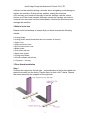
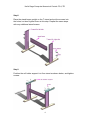
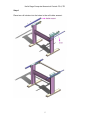
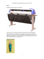
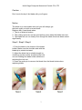
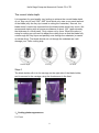
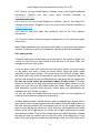
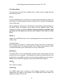
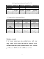
Hefei Saga Computer Numerical Control CO.,LTD
SAGA-720I
SAGA-720II
SAGA-1350I
SAGA-1350II
SAGA-1350IIP
SAGA-1750I
SAGA-1750II
SAGA-1750IIP
1
SAGA-720IIP
Hefei Saga Computer Numerical Control CO.,LTD
Congratulations on purchasing a Saga cutting plotter!
NOTICE:
We reserve the right to modify the information contained in this user
manual at any time without prior notice;un-authorized modification, copying or
distribution is prohibited. For all comments, queries or suggestions concerning
this manual please contact us.
Please read this guide carefully. It tells you how to prepare your cutting
plotter for production use in a few easy steps. We do not assume any liability
for direct or indirect damage that occurs due to the use of this product.
Precautions:
Please read these instructions and precautionary notes carefully before using
the machine for the first time.
● Don’t place magnetic objects near the cutting head as it will affect cutting
pressure and possibly damage the carriage mechanism.
● Don’t unplug the connection to the computer lead line when the plotter is
running as this may cause damage to plotter.
● Release the pressure contact rollers when not in use by flipping the pressure
levers up on the back side of the cutter.
● Keep your hands or other parts of the body far from the carriage when using
the machine.
● Never open the machine case and don’t attempt to modify the machine
without instructed to do so by a Saga technician.
● Avoid liquid spills and metal objects from entering the interior of the cutter.
● Insure the power supply is grounded. Do not bypass the ground lead for the
cutter. Grounding is very important for proper cutter function. Your stand
should be electrically connected to the vinyl cutter.
● Insure that the main power supply(220V/110V) doesn’t fluctuate by more
than ±10%. In case of extreme main power fluctuations, use a voltage
stabilizer.
● Unplug the power lead during long periods of inactivity.
● Keep your hands well away from the blade holder while the carriage is
running!
● Cancel the active job or preferably, power down the cutter before adjusting
the blade holder.
● Keep the cutting plotter away from children, and never leave the machine or
machine parts unattended when plugged-in.
● Do not touch the tips of the cutting blade to avoid injury and damage to the
blade tip. Blade tips are very delicate.
● Set up the machine on a stable base to avoid danger of falling.
2
Hefei Saga Computer Numerical Control CO.,LTD
● Never run the machine during a thunder storm as lighting could damage or
destroy the machine. During severe weather, unplug the machine.
● Do not use your hands to manually move the carriage, use the control
buttons in off-line mode instead. Manually moving the carriage can induce
currents from the motor into the motherboard, overload the electronics and
damage the machine.
2.What’s in the box
Please check immediately to ensure that you have received the following
articles:
● Cutting plotter
● Cutting plotter stand (dismantled and in the bottom of the box)
● Power cord
● USB connection Lead
● RS-232 connection Lead
● Blade holder
● Pen holder and pen
● Safety fuse (spare)
● 3 Drag knife blades
● CD with software and drivers.
● 1 Spanner, 1 hex key
3.Floor Stand Installation
Step1
Position the support for the left side perpendicularly to the bottom stand and
place the screws into the holes. Tighten them to form a left T-stand .Repeat
the same steps with the support for the right side
3
Hefei Saga Computer Numerical Control CO.,LTD
Step2
Place the stand beam upright on the T-stand and put the screws into
the holes, but don’t tighten them at this step. Repeat the same steps
with any additional stand beams.
Step3
Position the roll holder support’s to floor stand as shown below, and tighten
screws.
4
Hefei Saga Computer Numerical Control CO.,LTD
Step4
Place two roll holders into the holes in the roll holder support.
步进刻字
机
5
Hefei Saga Computer Numerical Control CO.,LTD
Step5
Installing the floor stand to the machine.
Remove the four nuts from the bottom of the machine mounting bolts and
insert the bolts from the bottom of the machine to the top of floor stand by
placing the cutter on the stand and aligning the four bolts with the slots in the
stand mounting flanges. Secure the machine to the stand using the nuts that
were removed from the mounting bolts.
4.Blade installation
6
Hefei Saga Computer Numerical Control CO.,LTD
Caution :
Don’t touch the tip of the blade with your fingers.
Notice
The blade is a consumable item and you will always get
the best quality cut with a newer blade.
Replace with a new blade when:
1. The tip of blade is broken.
2. The cutting traces are not as good as they were when the blade was new.
3. The blade will not cut cleanly even though the blade force has been raised
significantly.
Step1 / Step2 / Step3
1. Push the blade to the bottom of the blade
holder. Make sure the shoulder side with the
blade tip is pointed outward.
2. Adjust the blade tip to suitable length by
unlocking (rotate counter clockwise) the lock
nut and rotating the blade holder shield and
relocking the lock nut.
3. Press the push-pin to remove the blade form the blade holder when
replacing blade.
7
Hefei Saga Computer Numerical Control CO.,LTD
The correct blade depth
It is important for good quality vinyl cutting to achieve the correct blade depth
of cut. Sign vinyl is only .002”-.005” thick which only uses a very small amount
of the blade (only the very tip is used in cutting thin materials). As such, the
blade doesn’t need to be exposed from the blade holder shield very much. We
recommend starting with an exposure distance of about 1/32” (approximately
the thickness of a credit card). Vinyl cutters cut by force. When the cutter is
setup for cutting you will need to adjust the cutting force so that the blade fully
cuts through the vinyl layer and partially cuts through the substrate (or carrier
or release liner). The blade should not cut through the substrate as it will
damage your Teflon cutting strip.
Correct depth
too long
too short
Step 4
The blade holder will sit in the carriage on the right side of the blade holder,
and is secured to the carriage using the thumbscrew in the front.
专业研发, 设计, 生产制造伺服, 步进刻字
1、Cutting plotter appearance
5.1 Front
8
Hefei Saga Computer Numerical Control CO.,LTD
5.2 Rear
5.3 right-cap
9
Hefei Saga Computer Numerical Control CO.,LTD
5.4Panel
5.5Panel function
LCD screen:to display function and error messages.
Reset:to restart
Option:function keys.
Set:to set up function, can change XP/YP, Tool offset, sensitivity.
Test:to perform cutting test. This button will send a 1” triangle in a square test
coupon to the cutter. We recommend testing the cut each time you put new
vinyl in the machine. This test coupon does not have blade compensation or
overtravel.
Laser:On/Off laser.
Speed:to adjust the value of cutting speed and quality up.
Speed:to adjust the value of cutting speed and quality down.
Force:to adjust the value of cutting force up.
Force:to adjust the value of cutting force down.
Enter :to set item or register the immediately preceding input value. installing
and testing
6.1 set cutting plotter
● Insure that the machine is on a flat solid surface and keep the surrounding
environment clean and dry.
● The machine is suitable for 110V/220V voltage. Be sure to use the
corresponding voltage matching what your machine is set for. If you need the
machine converted from 110V to 220V or vice versa, contact Saga technical
support.
10
Hefei Saga Computer Numerical Control CO.,LTD
● When turning on the power switch, the carriage will automatically move to
the right and left and then stop. If you need to adjust the position of the
carriage press the on/off line button and use the arrow key to move the
carriage and vinyl. Do not use your hands to move the carriage as doing so will
cause a reverse current to flow into the motherboard which can potentially
damage the internal electronics of the machine.
6.2 USB lead and com cable (RS-232), connection from the cutting plotter to
the computer.
6.2-1 Installing the USB lead - USB2.0
The connection is suitable for MAC, Windows2000/2007 and Windows XP.
Windows 95, Windows 98 and Windows ME are not supported.
The machine is best run by vinyl cutting software such as DragonCut, Flexi,
Artcut, SignCut Pro etc. or can be driven by plug-ins through Illustrator or Corel
Draw on the PC.
6.2-2 How to install the USB print driver
Notice:Install the USB print driver prior to connector the cutting plotter to the
PC.
● Double-click the setup.exe file from the CD or the download link, the
computer will automatically install the USB driver as a new COM port.
● Connect the USB lead to the cutting plotter and the computer USB port.
● Windows will detect the cutting plotter and install the USB printing driver
automatically, be patient and give Windows sufficient time for recognition and
driver installation.
● If you have a 32 bit system the driver can be installed directly, if you have a
64bit system you will need to right click on the file and select run as
administrator. The installation file needs administrative privileges to install
properly. Also, the files should not be in a ZIP folder. If you have downloaded
the files from the internet and they are compressed in a ZIP folder extract them
into a normal folder before installing them.
● Check for the driver in Device Manager under universal serial bus controllers
/ USB printing support. If the USB printer support driver does not appear,
re-check the power and the USB connections to ensure the plotter is switched
on and connected properly.
6.3 How to use software
6.3-1 How to use and install ArtCut software, refer to the ArtCut instructions.
11
Hefei Saga Computer Numerical Control CO.,LTD
6.3-2 How to use and install SignCut software, refer to the SignCut software
instructions. SignCut has very good video tutorials available at
www.SignCutPro.com
6.3-3 How to use and install DragonCut software, refer to the DragonCut
software instructions. DragonCut has very good video tutorials available at
www.DragonCut.cn
6.3-4 How to use and install Flexi software, refer to the Flexi software
instructions.
6.3-5 How to use the external program, please refer to the external program
instructions.
Many Saga distributors offer training through phone or through screen sharing
services. Contact your point of purchase for training options and availability.
6.4 Loading media
● Always load media for processing from the rear of the machine. Saga vinyl
cutters cut from the front right corner to the left and to the back. Start your
carriage at the front right corner.
● Pull the pinch roller level upward to raise the pinch rollers, load your media
on the platen and slide it under the pinch rollers. Move the pinch rollers
manually to the proper position. The pinch rollers will slide left to right. While
the pinch rollers are in the raised position, grip the pinch roller from the front
and the rear and pull or push to slide the pinch roller along the top support rail.
Be sure the pinch rollers are positioned above the grit rollers. The white
marks on the top rail will help you position pinch rollers when media is on the
platen and you can’t see the rollers under the media. Push the pinch roller
level downward to lower down the pinch rollers when your adjustments are
complete and your media is in place.
● If you are using roll media rather than precut media, use the supplied roll
holder to ensure that the media unrolls smoothly.
● When loading media, ensure that the media is straight and aligned well to
the cutter to avoid bunching against the side walls of the cutter and to allow for
the best tracking possible. We recommend you roll out the media length you
plan on using during any given run. Verify that over this length that the media
doesn’t move left to right much. If it moves left to right, raise the pinch rollers
and rotate the media. Then roll the media again and check alignment. Repeat
this process until the media runs true with the cutter. In the beginning, it may
take a few trials to get the media running straight. After you have done this a
12
Hefei Saga Computer Numerical Control CO.,LTD
couple times you will find it easy to get the media properly aligned with the
machine.
● You can load the media at any position left to right along the machine
however, it is usually better to try to place the media near the center of the
machine. In addition, it is also advantageous to have 2 pinch rollers toward the
edges of the material.
●Fix the pressure rollers by snapping them into place at the outer edges of the
media, this helps to ensure straight feeding of the media and helps better
constrain materials such as heat transfer vinyl.
6.5 Setting the zero point
The zero point is the point on the loaded media where the plot job will start.
You usually need to set the zero point whenever you are ready to send a job to
the cutter. The cutter does not know where the media is. It also does not know
where the left and right ends of travel are. The travel is electronically limited by
optical limit switches embedded in the top rail. If you send a job to the cutter
that is too wide for the available cutting area, the carriage will trip the optical
limit switch and your image on the left or right side will be truncated /
compressed. Avoid running into the left or right side of the cutter by properly
calculating the width of your job and the width to the left of the zero point of
material you have available for cutting on.
● Switch the cutting plotter on.
● When the display reads Speed and Force, the cutter is in online mode and is
listening to the computer for instructions. In this mode, you can change the
speed and force (even while the cutter is cutting!)
● Press the online / offline button.
● You can now move the carriage and the vinyl using the arrow buttons
● If you move the carriage and the vinyl and then press the on / off line button
again, the carriage will move back to its original home position. This is because
the cutter remembers its origin point.
● If you move the carriage and the vinyl and then press the Enter button, the
carriage origin will be reset. This will be the new point that your cutter will start
cutting at when you send the next job. Since the cutter cuts from right to left,
we recommend setting the origin at the closest front right corner that you have
available to you. Always place the blade tip inside the perimeter of the media.
The cutter will start cutting from the exact origin. Always start with a little
margin from the edge of the vinyl. 1/2” (12 mm) is a good place to start. From
the front, always leave a little more margin. At least an inch, preferably more.
When the margin is too small, the front edge of the vinyl can catch on the
support plates.
13
Hefei Saga Computer Numerical Control CO.,LTD
6.6 Setting Mode
You can press the mode key multiple times in offline mode to toggle through
the following menus:
Force
Use the Left/Right keys to set the force in units of approximately one gram; the
valid range of values is between 0g and 750g (servo) or 0g and 510g (stepper),
2g or 3g per step.
When setting the cutting force, note that the correct setting mainly depends on
the blade holder, the position of the blade, and the loaded media. These
settings are subject to variation. Before cutting we highly recommend that
you press the test button and send a test coupon to the cutter to verify
force.
Speed :
Again use the UP/Down keys on the operating panel to set the speed while in
online mode.
X-Scale/Y-Scale
Don’t change the X-Scale or Y-Scale values as they are used to compensate
for wear and tear of the transport belts. Only change these settings, if plots
come distorted and you are instructed to do so by a technician.
Baud Rate:
The Baud Rate is the communication speed for the cutting plotter and the
serial port on your computer. This setting must reflect the baud rate set in the
properties for your COM port and in the vinyl cutting software you are using. A
default value of 38400 is typically set and rarely should be changed.
XP/YP:
Don’t need to change.
Sensitivity:
For ARMS cutters, this is based on the reflective intensity of the media.
Adjustments are made to this setting if your ARMS laser doesn’t detect the
alignment markers on the vinyl.
14
Hefei Saga Computer Numerical Control CO.,LTD
Fan setting:
For ARMS cutters the fan speed and resultant vacuum pressure can be
adjusted.
Additional setting in the display:
NO/Off (pause the plot)
Press this key to pause the current plot; you can then modify prior settings.
The display now shows the force and speed; both values can be modified.
If you want to pause of cutting, you can press the test key. If you want to end
the cut job, please press the reset key.
6.7cutting test
●Press the Test key to perform a cutting test. The cutting plotter will now cut a
square containing a triangle divided into four quadrants. (This test coupon
does not have blade offset or over-travel built into it.)
●The cutting test helps you verify the blade holder setting and cutting pressure.
The cutting test should give you clean and straight cuts in the loaded media.
You should cut partially through the substrate but not completely through it.
●If the test cuts through the substrate, either the cutting force is too high, or the
blade (too sharp perhaps) or blade holder setting is incorrect. Change these
setting and repeat the cutting test until you get satisfactory results.
7.After cutting
7.1. Weeding
Weeding refers to the process of removing the
parts of the media you don’t require.
We recommend using a scalpel or a special
weeding tool for this job to avoid damage to
the adhesive surface. After weeding, you can
use a transfer press to transfer flock and flex
media to the textiles to be processed or apply
application tape to self-adhesive media before transferring.
7.2. Apply
15
Hefei Saga Computer Numerical Control CO.,LTD
Apply application tape to the weeded
material and use a roller or flat scraper to
press down firmly. Next, lift your graphics off
of the substrate with the application tape.
Your graphics will now be on the application
tape. Next, press this decal on your target
surface. Press firmly with a squeegee so the
media adhesive adheres to the target surface.
Finally, peel off your application tape leaving
the decal on the target surface. (Application
tape can sometimes be reused. Place the
used transfer tape on the release liner from
your cut vinyl for next use.)
8. Blade
Blades are extremely sensitive, very sharp and dangerous precision
cutting tools.
● Always keep blades well out the reach of children.
● To avoid danger of injury, always handle blade with caution.
● Handle blades with caution and always replace the protective cap when not
in use. If the tip of the blade comes into contact with a hard material such as
following glass or stone, tiny fissures may occur at the blade tip making the
blade useless. Note the following to avoid unnecessary wear and tear on the
blade and to ensure maximum working life.
● Avoid cutting the backing of loaded media. The deeper you cut into the
loaded material, the more wear and tear the blades are exposed to.
● Always set the cutting depth of the blade to cut the media precisely and
cleanly without cutting too deep. Extending the blades beyond the required
cutting depth impacts the service life of the blades without achieving better
cutting results.
● Always use the right custom blades for thicker material.
● Ragged edges on cutting the loaded media may indicate that the blades are
dull or damaged. Always replace dull blades.
● We highly recommend that you examine the tip of the blade with a small
magnifying glass or jeweler’s scope prior to cutting. It is very difficult to
determine if a blade is damaged without the use of a magnifying glass. Only
the very .002” - .004” of the tip gets utilized in cutting. In order to see any
damage to the leading .002” - .004” of the tip of the blade a magnifier is
needed.
9.Basic maintenance
9.1Cleaning the cutting plotter
16
Hefei Saga Computer Numerical Control CO.,LTD
In order to keep the cutting plotter under good condition and best performance,
you need to clean the machine properly and regularly.
Precaution in cleaning
Unplug the cutting plotter before cleaning. Never use solvents, abrasive
cleaners or strong detergents for cleaning. They may damage surface of the
cutting plotter and moving parts.
Recommended Methods
● Gently wipe the cutting plotter surface with a lint-free cloth. If necessary,
clean with a damp cloth or an alcohol-immersed cloth. Wipe with water to rinse
off any residue and dry with a soft, lint-free cloth.
● Wipe all dust and dirt from the tool carriage rails.
● Use a vacuum cleaner to empty any accumulated dirt and media residue
from beneath the pinch roller housing.
● Clean the platen, paper sensors and pinch rollers with a damp cloth and dry
with a soft, line-free cloth.
● Wipe dust and dirt from the stand.
9.2 Cleaning the grit roller
●Turn off the cutting plotter, and move the tool carriage away from the area
needed to be cleaned slowly.
● Raise the pinch rollers and move them away from the grit roller for cleaning.
●Use a bristle brush (a toothbrush is acceptable) to remove dust from the grit
roller surface. Rotate the grit roller manually while cleaning.
9.3 Cleaning the pinch rollers
If the pinch rollers need a thorough cleaning, use a lint-free cloth or cotton
swab to wipe away the accumulated dust from the rubber portion of the pinch
rollers. To prevent the pinch rollers from rotating while cleaning, use your finger
to hold them in place. If needed to remove the embedded or persistent dust,
use the lint-free cloth or cotton swab moistened with rubbing alcohol.
Note:
Daily maintenance of your cutting plotter is very important. Be sure to clean the
grit rollers and pinch rollers regularly for better cutting accuracy and output
quality.
17
Hefei Saga Computer Numerical Control CO.,LTD
10.Technical specifications cutting plotter
10.1 Servo ARMS machine technical specifications
Item NO.
Max media width
Max cutting width
Accuracy
Connectors
Drive
Power consumption
Ambient temperature
Meas
G.W/N.W
SAGA-720IIP SAGA-1350IIP
720mm
1350mm
630mm
1200mm
+/-0,01m
+/-0,01m
USB/RS-232
USB/RS-232
Servo
Servo
<100w
<100w
+5℃-+35℃
+5℃-+35℃
97×34×43cm 160×34×41cm
27.5/25kgs
38/35kgs
SAGA-1750IIP
1750mm
1660mm
+/-0,01m
USB/RS-232
Servo
<100w
+5℃-+35℃
207×36×51cm
52/47kgs
10.2 Stepper ARMS machine technical specifications
Item NO.
Max media width
Max cutting width
Accuracy
Connectors
Drive
Power consumption
Ambient temperature
Meas
G.W/N.W
SAGA-720IP
720mm
630mm
+/-0,01m
USB/RS-232
Stepper
<100w
+5℃-+35℃
97×34×43cm
27.5/25kgs
SAGA-1350IP
1350mm
1200mm
+/-0,01m
USB/RS-232
Stepper
<100w
+5℃-+35℃
160×34×41cm
38/35kgs
10.3 Servo machine technical specifications
Item NO.
Max media
width
Max cutting
width
Accuracy
SAGA-490II
SAGA-720II
SAGA-1350II
SAGA-1750II
420mm
720mm
1350mm
1750mm
330mm
630mm
1200mm
1660mm
+/-0,01m
+/-0,01m
+/-0,01m
+/-0,01m
18
Hefei Saga Computer Numerical Control CO.,LTD
Connectors
Drive
Power
consumption
Ambient
temperature
Meas
G.W/N.W
USB/RS-232
Servo
USB/RS-232
Servo
USB/RS-232
Servo
USB/RS-232
Servo
<100w
<100w
<100w
<100w
+5℃-+35℃
+5℃-+35℃
+5℃-+35℃
+5℃-+35℃
66×33×32cm
10/9kgs
97×34×43cm
27.5/25kgs
160×34×41cm
38/35kgs
207×36×51cm
52/47kgs
专业研发, 设计, 生产制造伺服, 步进刻字
10.4 Stepper machine technical specifications
Item NO.
Max media width
Max cutting width
Accuracy
Connectors
Drive
Power
consumption
Ambient
temperature
Meas
G.W/N.W
SAGA-420I
420mm
330mm
+/-0,01m
USB/RS-232
Stepper
SAGA-720I
720mm
630mm
+/-0,01m
USB/RS-232
Stepper
SAGA-1350I
1350mm
1200mm
+/-0,01m
USB/RS-232
Stepper
<100w
<100w
<100w
+5℃-+35℃
+5℃-+35℃
+5℃-+35℃
66×33×32cm
10/9kgs
97×34×43cm
27.5/25kgs
160×34×41cm
38/35kgs
Warning prompt:
If for some reason you are unable to cut with your
vinyl cutter or for errors that are not covered in the
scope of this user guide, please contact your point of
purchase or distributor for additional service.
19