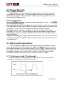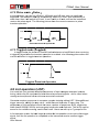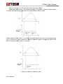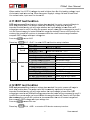
1
IT880 00 User Manual U r’s Man User M ual DC program p mmablle electtronic load Mod del IT88817/IT8817B/IT88817C IT88 818/IT88 818B/IT8818C ht Reserve ed © Copyright 2010 All Righ Ver1.2 /O Oct, 2013/ IT8800-70 01 1 User Manual M IT880 00 User Manual DIRE ECTOTRY CHAPTE ER1 INSPE ECTION AND INSTA ALLATION ............................................................ 7 1.1 INS SPECTION .............................................................................................................. 7 1.2 CLE EANING ................................................................................................................. 7 1.3 ACCESSORY C ............................................................................................................. 7 1.4 INS STALLATIONSITE ..................................................................................................... 7 1.4.1 Mounting g Dimensio ons....................................................................................... 7 1.4.2 INPUT CONN NECTIONS .............................................................................................. 8 CHAPTE ER 2 QUIC CK START ............................................................................................ 9 2.1 POWER O -ON SE ELFTEST ................................................................................................ 9 2.1.1 Introducttion ...................................................................................................... 9 2.1.2 2 Selftest steps s ................................................................................................... 9 2.1.3 3 If the ele ectronic loa ad can’t power-on ................................................................ 9 2.2 FRONT R PANEL L INTRODUCT TION ................................................................................... 10 2.3REA AR PANEL IN NTRODUCTIO ON...................................................................................... 11 2.4 VF FD STATUS INDICATOR I LAMP DESC CRIPTION .............................................................. 12 2.5 KEY BOARD DE ESCRIPTION N......................................................................................... 12 2.6 COMBINATION O N KEYS ................................................................................................. 13 CHAPTE ER3 TECH HNICAL SP PECIFICAT TION .................................................................. 14 3.1 MAIN A TECHNIC CAL SPECIFICATION ............................................................................... 14 3.2 SUPPLEMENTA U ARY CHARA ACTERISTIC........................................................................... 17 CHAPTE ER4 FUNC CTION AND D CHARAC CTERISTIC C........................................................ 18 4.1LOC CAL/REMOT TE OPERATIO ON MODE ............................................................................ 18 4.2 OPERATION P M MODES ................................................................................................. 18 4.2.1Constant current mode(CC) ) ....................................................................... 18 4.2.2 2 Constant voltage mode(CV) m ) ...................................................................... 19 4.2.3 3 Constant resistancce mode(C CR) ................................................................. 19 4.2.4 4 Constant power mo ode(CW) ) ....................................................................... 20 4.3 INP PUT CONTROL ...................................................................................................... 20 4.3.1 Input switch operattion .................................................................................... 20 4.3.2 2 Short op peration .............................................................................................. 20 4.4 SYSTEM Y MENU U(SYSTEM M) ..................................................................................... 20 4.5 CONFIG O MENU U(CONFIG) ...................................................................................... 21 4.6 TRIGGER R FUNC CTION ................................................................................................. 23 4.6.1 TRIGGER FU UNCTION .............................................................................................. 23 4.6.2 TRIGGER SO OURCE ................................................................................................ 23 4.7 A/B B TRANSIEN NT OPERATIO ONS .................................................................................... 23 4.7.1 Continuo ous mode( (Continuo ous) .................................................................. 23 2 Pulse mo ode(Pulse) .................................................................................... 24 4.7.2 4.7.3 3 Toggled mode (Tog ggled) ................................................................................ 24 4.8 LIS ST OPERATIO ON (LIST) ........................................................................................... 24 4.9 SAVE A AND REC CALL FUNCT TION .................................................................................... 25 4.10 VON V FUNCTION..................................................................................................... 25 4.11 OCP O TEST FUNCTION............................................................................................. 27 User Manual 2 IT880 00 User Manual 4.12 OPP O TEST FUNCTION ............................................................................................. 27 4.13 BATTERY DIS SCHARGING TEST ................................................................................. 28 4.14 PROTECTION N FUNCTION NS ....................................................................................... 29 4.14.1 OVER VOLTAGE O PROTECTION R ( (OVP) ............................................................ 29 4.14.2 OVER CURRENT PROTECTION R ( (OCP) ........................................................... 29 4.14.3 OVER POWER O PROTTECTION(O OPP) ............................................................... 30 4.14.4 OVER TEMPERATUR E RE PROTECTION(OTP P) .................................................... 30 4.14.5 REVERSE VOLTAGE PROTECTIO ON(LRV) ) ........................................................ 30 4.15 KEY LOCK FUNCTION ............................................................................................. 31 4.16 REAR PANEL INTERFACE ES INTRODUCTION ................................................................. 31 4.16.1 REMOTE E SENSE FUN NCTION ............................................................................... 31 4.16.2 EXTERNA AL TRIGGER R OPERATIO ON ....................................................................... 31 4.16.3 EXTERNA AL ANALOG GUE CONTRO OL ...................................................................... 32 4.16.4 VOLTAGE FAILURE INDICATION ......................................................................... 32 4.16.5 CURREN NT MONITOR RING(I MONITOR) ............................................................. 32 CHAPTTER5 OPERA ATION INTRO ODUCTIONS S ......................................................................... 33 5.1 OPERATION P M MODES ................................................................................................. 33 5.1.1 Constant current CC C ...................................................................................... 33 2 Constant voltage CV C ...................................................................................... 33 5.1.2 5.1.3 3 Constant power CW W ....................................................................................... 34 5.1.4 4 Constant resistancce CR ................................................................................. 34 5.2 TRANSIENT R TE EST OPERAT TION .................................................................................... 34 5.2.1 Transien nt test operration in co ontinuous mode m ................................................. 35 2 Transien nt test operration in pu ulse mode .......................................................... 35 5.2.2 5.2.3 3 Transien nt test operration in To oggled mod de ...................................................... 36 5.3 LIS ST OPERATIO ON ...................................................................................................... 37 5.4 AUTOMATIC U TESTING FUN NCTION ............................................................................... 38 CHAPTE ER 6 COMMUNICAT TION INTER RFACES ........................................................... 41 6.1 RS S232 INTER RFACE .................................................................................................. 41 6.2 USB U INTERF FACE ................................................................................................... 43 6.3 GPIB G INTERF FACE .................................................................................................. 43 3 User Manual M IT880 00 User Manual Warrranty y Info ormattion Certiffication n We certiffy that this product met m its published spec cifications at time of sshipment from f the factory. Warra anty This hard dware prod duct is warrranted aga ainst defec cts in mate erial and wo orkmanship for a period off ONE year from date e of deliverry. IT8800 series elecctronic load for use with w a hardware e product and a when properly in nstalled on that hardw ware produ uct, are wa arranted not to faiil to executte their pro ogramming g instructions due to defects d in m material an nd workman nship for a period of 90 9 days fro om date of delivery. During D the warranty period p our companyy will eitherr repair or replace prroducts which prove to t be defecctive. Our company c does nott warranty that the op peration forr the softw ware firmwa are or hard dware shalll be uninterru upted or errror free. For warranty servicce, with the e exception n of warran nty optionss, this prod duct must be b returned to a servicce facility designated d d by our company. Cu ustomer sh hall prepay y shipping charges by (and sh hall pay all duty and taxes) t for products p re eturned to our place for warrantyy service. Our O compa any shall pa ay for returrn of produ ucts to Cusstomer. Limita ation of o Warrranty The foreg going warrranty shall not apply to defects resulting from f impro oper or inad dequate maintena ance by the e Custome er, Custom mer-supplie ed software e or interfaccing, unauthorized modificattion or missuse, opera ation outsid de of the environmen e ntal specifications forr the product, or imprope er site prep paration an nd mainten nance. Assis stance The abovve stateme ents apply only to the e standard product warranty. w W Warranty op ptions product maintenan m ments and customer c assistance a e agreemen nts are also o ce agreem available e. Safety y Summary The follo owing gene eral safety precaution p ns must be observed during all p phases of operation o of this insstrument. Failure to comply c witth these prrecautions or with spe ecific warn nings elsewherre in this manual m violates safetyy standard ds of design n, manufaccture, and intended use of th he instrume ent .We assumes no liability forr the customer’s failure to comp ply with these req quirementss. Envirronmen ntal Co ondition ns This instrument is intended i fo or indoor use. u Pollutio on degree 2 environm ments. It is s designed d to operatte at a maxximum rela ative humid dity of 95% and at altiitudes of up to 2000 meters. Refer R to the specifica ations table es for the ac a mains voltage v requirements and ambient operating temperature range. Beforre Appllying Power P Verify tha at all safety precautio ons are takken. Note the t instrum ment's exte ernal markings described under "S Safety Sym mbols". User Manual 4 IT880 00 User Manual Groun nd the Instrument This prod duct is a Safety Classs 1 instrum ment (provided with a protective e earth term minal). To minimize e shock hazzard, the in nstrument chassis an nd cover must m be con nnected to o an electrical ground. The T instrum ment must be connec cted to the ac power mains thro ough a grounded d power ca able, with the t ground d wire firmly y connecte ed to an ele ectrical gro ound (safety ground) g at the t power outlet. Notte: Any inte erruption of o the prote ective (grou unding) conducto or or discon nnection of o the prote ective earth h terminal will w cause a potentiall shock hazard th hat could result r in pe ersonal inju ury. DO NOT OPERATE O I AN EXPL IN LOSIVE ATM MOSPHERE E Do not operate the e instrumen nt in the pre esence of fumes or flammable f gases. KEEP AW WAY FROM LIVE CIRCUITS Operatin ng personnel must no ot remove instrument i t covers exxcept as insstructed in this Guide for installing or removing electron nic load modules. Co omponent replaceme ent and internal adjustment a ts must be e made onlyy by qualiffied service e personne el. Do not replace r compone ents with power p cable e connecte ed. Under certain c con nditions da angerous voltages v may exisst even with h the powe er cable rem moved. To o avoid inju uries alwayys disconne ect power, discharge circuits, and removve external voltage sources beffore touchiing components. DO NOT T SERVICE E OR ADJU UST ALON NE Do not trry to do som me interna al service or o adjustme ent unless another pe erson capa able of rendering g first aid resuscitatio r on is prese ent. Safety y Symb bols Dirrect curren nt Altternating current Bo oth direct and alternating curren nt Prrotective ea arth (groun nd) termina al Ca aution (refe er to accom mpanying documents d s) WARN NING The WAR RNING sig gn denotess a hazard. It calls atttention to a procedure, practice e, or the like, whicch, if not co orrectly performed orr adhered to, t could re esult in perrsonal injurry. Do not proceed beyond a WARNING G sign untill the indica ated condittions are fu ully unders stood and met. CAUT TION The CAU UTION sign n denotes a hazard. It calls atte ention to an n operating g procedurre, or the like, whicch, if not co orrectly pe erformed orr adhered to, t could re esult in dam mage to orr destruction of part or all of the e productss. Do not proceed beyyond a CA AUTION sig gn until ated condiitions are fully f undersstood and met. the indica 5 User Manual M IT880 00 User Manual Introductio on IT8800 series s DC electronic e l loads are singel-chan s nnel progra ammable e electronic loads. l With RS2 232 /GPIB /USB com mmunicatio on interface es. The series DC ele ectronic loa ads can provide multiple m so olutions acccording to the require ements of your y desig gn and test. Feature:: • Highligh ht VFD dissplay • Measurrement ressolution: 0.1mV,0.01m mA • Measurrement spe eed: up to 50KHZ • Four op peration mode:CV(Co onstant Vo oltage),CC,CR,CW • Rotary knob, makking the op peration mo ore easier • Remote e Sense fu unction • Batteryy test functiion • Memory capacity to save/re ecall setting g paramete ers:100 sets • Short circuit c functtion • With skkid-resistan nt tripod an nd portable e firm chas ssis • Controllled by inte elligent fans • Build-in n Buzzer ass alarm sig gnal • Power off memorry function Model IT8817 IT8817B IT8817C C IT8818 IT8818B IT8818C C User Manual Volltage 120 0V 500 0V 120 0V 120 0V 500 0V 120 0V Current 360A 120A 600A 480A 150A 720A Pow wer 450 00W 360 00W 450 00W 600 00W 500 00W 600 00W 6 IT880 00 User Manual Chap pter1 Inspe I ction and Install I lation n 1.1 Inspectio on Make sure you havve received d the follow wing compo ontents alo ong with un nit.If anyon ne has been lost,please co ontact with h your francchiser. Item Power cord Part Number IT--E171 IT--E172 IT--E173 IT--E174 User’ss manua al Test rep port Description yyou can cho oose differe ence power line a according to o region including installation ,o operation,se elf-test information t test report before b ex-fa actory 1.2 cleaning g Do not clean any in nternal parrts of units casually.Iff you want to clean th he outside cover,ple ease use a dry cloth or moistish h cloth to wipe. w C Caution:Cu ut the pow wer source e before do d the clea aning 1.3 Ac ccesso ory Standard Accesso ories Power co ord User’s manual m Calibratio on testing report 1.4 Installationsite e The follo owing outside drawing g has markked the dim mension infformation.U Unit should d be fixed in a reassonable sizze of space e and make e sure prop per ventilation condittions. 1.4.1 Mounting M g Dimen nsions dimensio on:465 mmW m x 263 3.5mm H x 535.5mm D Refer to the following dimenssion drawin ng: 7 User Manual M IT880 00 User Manual Unitt:minimetter(mm) 1.4.2 In nput con nnection ns Power Cord Connect the powerr cord to th he IEC 320 0 connector on the rear of the unit. If the wrong w power co ord was sh hipped with h your unit, contact yo our nearesst Agent to obtain the e correct cord. See following g figure for the part number and d ordering options. E N E E L China IT-E171 User Manual L E N N ates ,Canad da United Sta IT-E172 2 Europe IT-E1 173 8 L L N ngdom United Kin IT-E174 IT880 00 User Manual Cha apter 2 Qu uick Start S 2.1 Po ower-o on selfttest 2.1.1 In ntroducttion A successsful test process p ind dicates thatt units mee et the facto ory specificcations and d can be operated d well. 2.1.2 Selftest S s steps Power co ord should be conneccted correcctly.Follow wing is the detailed d se elftest step ps. Ste eps VF FD display After turn on the un nit BO OIS Ver 1.10 About 1S later About 1S later Press + numb ber 7 Expla anations display sofftware verssion Syste em Selftes st…. System se elf check 0.000 00V VFD:the V first line display actua al voltage and a current value VFD:the V se econd line display the actual power valu ue and the setting current/voltage/powe er/resistanc ce/impeda ance value v 0.00W W 0.000 00A CC=0.00 00A Mod del:IT88X XX Display pro oducts’s in nformation..You can press direcction buttons to chec ck product’ss Ver: :1.XX-1.X XX model/SN/ /software v version S SN:XXXXX XXXXXXXX XXXXXXX WARNING G:The electronic load is shiipped from m factory w with a pow wer cord that has a plug app propriate for f your lo ocation. Your Y electrronic load is equipped d with 3-wire ground ding type power cord; the thiird conduc ctor being gro ounded. The electro onic load is grounde ed only wh hen the po ower-line cord is pllugged intto an apprropriate re eceptacle.. Do not op perate you ur power supply without w ade equate cab binet grou und conne ection. 2.1.3 Iff the electronic load can n’t powe er-on The follo owing mean ns could he elp you solve some problems p y may m you meet when you turn on the un nits: 1) Veriffy that the ere is AC power p to the t power supply. First, verrify that the e power co ord is firmlyy plugged into the power recepttacle on the rear panel of the electro onic load. You Y should d also mak ke sure tha at power so ource you plugged p ergized. Th hen, verify that the ele ectronic lo oad is turne ed on. the electtronic load into is ene 2) Veriffy the pow wer-line vo oltage settting The line voltage is set to the proper p valu ue for yourr country(110VAC or 220VAC) when the electronic load is shipped from facory. Change C the line volta age setting g if it’s not correct. c 3) Veriffy that the e correct power-line p e fuse is in nstalled. 9 User Manual M IT880 00 User Manual If fuse is blowout, please p replace it acco ording to th he followin ng specifica ation. Model IT8817 IT8817B B IT8817C C IT8818 IT8818B B IT8818C C Fuse specificatio on(110AC) T 5A A 250VAC C T 5A A 250VAC C T 5A A 250VAC C T 5A A 250VAC C T 5A A 250VAC C T 5A A 250VAC C Fuse spe ecification(2 220AC) T 2.5A 250VAC T 2.5A 250VAC T 2.5A 250VAC T 2.5A 250VAC T 2.5A 250VAC T 2.5A 250VAC 4) The method m to replace fu use Use a fla at-bladed screwdriver s r to open th he small plastic cove er under the AC inputt connecto or on the re ear panel of o the load ,then you can see th he fuse. Please use the t matching g fuse.(fig gure showss the fuse location) Fuse 2.2 Frront pa anel inttroducttion User Manual 10 IT880 00 User Manual The e power sw witch VFD D display Rota ary knob Ope eration mod de(CC,CV,CR,CW) keys k Dire ection butto ons Fun nction keyss Num mber keys// Compositte function keys 2.3 Re ear pan nel intrroductiion Inpu ut terminal Currrent detecction termin nal Rem mote sense e terminal, external trrigger term minals, 0-10 0V anolog control inte erfaces Exte ernal signa al control in nterface RS2 232 communication interface USB commun nication intterface GPIIB commun nication intterface AC power switching(110V/220V) ) AC power inp put socket (with fusse in it) ns Fan 11 User Manual M IT880 00 User Manual 2.4 VF FD stattus ind dicator lamp descrip d ption The load is in OFF state Constantt current mode m Error CC CV Constantt voltage mode m Sense CR Constantt resistance e mode Prot CW Constantt power mo ode Rear Rmt Remote control c mo ode Auto OFF Addr SRQ Send com mmand in remote control mode m Serial req quest enqu uire Trig Something wrong happened d Waiting for the trig gger signal Remote e sense fun nction is enabled d Software OCP sta ate External analog co ontrol func ction is open Voltage range automatically seleting function iss open * The keyy lock functtion is open shift Shift has been pre essed 2.5 Ke ey boa ard des scriptio on Shift( composite e key) Recalll paramete ers that havve been sa aved,such as currentt setting g value Set the dynamicc test param meters Trigge er button,open triggerr function Set the parametters of List test file Pause e if needed d during au uto-test Selectt constant current md doe,set currrent level Selectt constant voltage mo ode,set the e voltage le evel Selectt constant resistance e mode,se et the resisstance value Selectt constant power mod de,set the power va alue Ensurre button Contro ol the inputt mode:o on/off Up arrrow button,move upw words in menu/increa ase the sett User Manual 12 IT880 00 User Manual value Down arrow,movve downwo ords in me enu/decrease the set value e Right arrow,movve the curssor to the riight when in set mode Left arrrow,move e the cursor to the right when in n set mode Confirrm button 0 ~ numbe er keys 9 radix point p key Exit ke ey,exit fro om any operation condition ×10 0 Rotaryy knob to adjust a the setups s by 10 1 stepping ×1 Rotaryy knob to adjust a the setups s by 1 stepping 2.6 Co ombina ation keys k + number1(Short) ) start or stop shortt test function Auto test function n + number 3(Battery) ) Batteryy test functiion + number 2(pragma) he current setting value,such ass current setting s + number 4(Save) ) Save th value System m menu settting + number 5 (Syste em) ure menu setting s + number 6(Config) ) Configu N/Version + number 7(Info) Displayy product’s Model/SN + number 8(Lock) ) Key locck function L key,use ed to switch h local and d remote mode m + number 9(Local) ) LOCAL OCP te est function n +CC(OC CP) +CV(Setup) Set dettailed param meters in CC/CV/CW C W/CR mode e +CW(OP PP) OPP te est function n 13 User Manual M IT880 00 User Manual Ch hapterr3 Tec chnica al Spe ecifica ation 3.1 Main tec chnicall speciffication n Model IT8818 IT8 8817 Voltage e 0~12 20V 0~120V Currentt 0~36A 0~ ~360A 0~48A A 0~480A Rated value power 450 00W 6KW ( 0~40 ℃) Minimum m setting 0.15V/36A 1.5V/3 360A 0.15V/48A A 1.5V/480A 1 voltage e range 0~ ~18V 0~120V 0~18V 0~120V resolutio on 1 mV 10m mV 1mV 10mV CV mod de ±(0.025%+0.0 ± 05%F ±(0.0 025%+0.05% %F accuraccy ±(0.025%+0.05%FS) ±(0.025%+0 0.05%FS) S) S) range 0~ ~36A 0~36 60A 0~48A A 0~480A 10m mA 10mA resolutio on 1 mA 1mA CC mod de ±(0.05%+0 0.1%FS) accuraccy ±(0.05%+0.1%FS) range 0.01Ω Ω~10Ω 10Ω~7.5KΩ on 16 6bit CR mod de resolutio 0.01%+0.0008S accuraccy 0.01% %+0.08S range 450 00W CW mod de resolutio on 100mW accuraccy 0.2%+0 0.2%FS 05%+0.1%FS S) ±(0.05%+0.1% ± %FS) ±(0.0 0.005Ω~10 0Ω 10Ω~7.5KΩ 16bit 0.01%+0.0008S S 0.01%+0.0 08S 6KW 100mW 0 0.2%+0.2%F FS Mea asurement range Readbac ck voltage e Range Resolutio n 0~ ~18V 0~12 20V 0~18V 0~120V 1 mV 10m mV 1 mV 1 0mV Accuraccy ±(0.025% %+0.025%FS) Readbac ck currentt Readback k power Range Resolutio n Accuraccy Range Resolutio n Accuraccy 0 0~36A ±(0.025%+ +0.025%F ±((0.025%+0.0 025%F ±(0.025%+0.025% %F S) S) S) 0~3 360A 0~48A A 0~480A 1 1mA 10m mA 1mA 10mA ±(0.05%+0 0.05%FS) 450 00W ±(0.05%+0.05% %FS) 6KW 100mW 100mW ±(0.2%+0 0.2%FS) ±(0.2%+0.2%F FS) Prrotection range r OPP OCP OVP OTP ≒6050W ≒4550W ≒39.6A A ≒39 96A ≒52.8A A ≒130V ≒85℃ ≒528A ≒130V ≒85℃ specificattion Short currentt (CC) ) voltage e (CV) ) resistanc e(CR) ) Input User Manual ≒39.6A ≒39 96A ≒52.8A A ≒528A 0V 0V V 0V 0V ≒ ≒4mΩ ≒4m mΩ ≒3mΩ ≒3mΩ 300KΩ 300KΩ 14 IT880 00 User Manual termina al impedenc ce Model IT8818B IT8817B Voltage e 0~50 00V 0~500V Currentt 0~ ~12A 0~120A 0~15A 0~150A Rated value power 3.6K KW 5KW ( 0~40 ℃) Minimum m setting 0.3V V/12A 3V/120 0A 0.3V/15A 3V/150A 3 voltage e range 0~ ~50V 0~500 0V 0~50V 0~500V on 1mV 10mV V 1mV 10mV CV mod de resolutio ±(0.025%+0 0.05%F ±(0 0.025%+0.05 5%F accuraccy ±(0.025%+0.05%FS) ±(0.025%+0.05%F FS) S) S) range 0~ ~12A 0~120A 0~15A 0~150A 10mA A 10mA on 1mA 1mA CC mod de resolutio 05%FS) ±(0.05%+0.05% 5%+0.05%FS S) accuraccy ±(0.05%+ +0.05%FS) ±(0.05%+0.0 %FS) ±(0.05 range 0.03Ω Ω~10Ω 10Ω~7.5 5KΩ 0.03Ω~10Ω Ω 10 0Ω~7.5KΩ on 16b bit 16bit CR mod de resolutio 0.01%+0..0008S 0.01 1%+0.0008S S accuraccy 0.01% %+0.08S 0.01%+0.08S range 3.6K KW 5KW CW mod de resolutio on 100m mW 100mW accuraccy 0.2%+0.2%FS 0.2%+0.2%FS S Mea asurement range Readbac ck voltage e Range Resolutio n Accuraccy Readbac ck currentt Readbac ck power Range Resolutio n Accuraccy Range Resolutio n Accuraccy 0~ ~50V 0~500 0V 0~50V 0~500V 1 mV 10 mV m 1 mV 10 mV ±(0.025% %+0.025%FS ±(0.025%+ +0.025% ±(0.025%+0.025%F ±(0.025 5%+0.025%F FS ) FS)) S) ) 0~12A 0~12 20A 0~15A 0~150A 1mA 10mA A 1mA 10mA ±(0.05%+0 0.05%FS) 3.6K KW ±(0.0 05%+0.05%FS) 5KW 100m mW 100W ±(0.2%+0 0.2%FS) ±(0 0.2%+0.2%FS) Prrotection range r OPP OCP OVP OTP ≒5050W ≒3650W ≒13.2A A ≒132 2A ≒16.5A ≒530V ≒85℃ ≒165A ≒530V ≒85℃ specificattion Short Input termina al impedenc ce currentt (CC) ) voltage e (CV) ) resistanc e(CR) ) ≒1 13.2A ≒132 2A ≒16.5A ≒165A 0V 0V 0V 0V ≒2 25mΩ ≒25m mΩ ≒20mΩ ≒20mΩ 1MΩ 1MΩ 15 User Manual M IT880 00 User Manual Model IT8818C C IT88 817C Voltage e 0~12 20V 0~120V Currentt 0~ ~600A 0~60 00A 0~72A 0~720A Rated value power 450 00W 6KW ( 0~40 ℃) Minimum m setting 0.18V/60A 1.8V/6 600A 0.18V/72A A 1.8V/720A voltage e range 0~ ~18V 0~120V 0~18V 0~120V on 1mV 10m mV 1mV 10mV CV mod de resolutio ±(0.025%+0.0 ± 05% accuraccy ±(0.025%+0.05%FS) ±(0.025%+0 0.05%FS) ±(0.025%+0.05%F FS) FS) range 0~ ~60A 0~60 00A 0~72A 0~720A 10m mA 10mA on 1mA 1mA CC mod de resolutio ±(0.1%+0.1%FS) ±(0.1 1%+0.1%FS)) accuraccy ±(0.1 %+ +0.1%FS) ± ±(0.1%+0.1% %FS) range on CR mod de resolutio accuraccy range CW mod de resolutio on accuraccy 0.01Ω Ω~10Ω 10Ω~7..5KΩ 16 6bit 0.01%+0 0.0008S 450 00W 100mW 0.2%+0 0.2%FS 0.01% %+0.08S 0.005Ω~10 0Ω 10 0Ω~7.5KΩ 16bit 0.01 1%+0.0008S S 0.01%+0.08 8S 6KW 100mW 0 0.2%+0.2%F FS Mea asurement range Readbac ck voltage e Range Resolutio n Accuraccy Readbac ck currentt Readbac ck power Range Resolutio n Accuraccy Range Resolutio n Accuraccy 0~ ~18V 0~12 20V 0~18V 0~120V 0.1 1 mV 1 mV m 1 mV 10mV ±(0.025% %+0.025%FS ±(0.025%+ +0.025%F ±(0.025%+0. ± 025 ±(0.025 5%+0.025%F FS ) S)) %FS) ) 0~60A 0~60 00A 0~72A 0~720A 1mA 10m mA 1mA 10mA ±(0.05%+ +0.1%FS) 450 00W ±(0 0.05%+0.1%FS) 6KW 100mW 100mW ±(0.2%+0 0.2%FS) ±(0.2%+0.2%F FS) Prrotection range r OPP OCP OVP OTP ≒4550W ≒6050W ≒66 6A ≒66A ≒79.2A ≒130V ≒85℃ ≒792A ≒130V ≒85℃ specificattion Short currentt (CC) ) voltage e (CV) ) resistanc e(CR) ) Input termina al impedenc ce User Manual ≒ ≒66A ≒66 60A ≒79.2A ≒792A 0V 0V V 0V 0V ≒3mΩ ≒3m mΩ ≒2.5mΩ ≒2.5mΩ ≒ 300KΩ 300KΩ 16 IT880 00 User Manual 3.2 Su upplem mentary y chara acteris stic Memory y capacity: :100 groups ation frequ uency:1ttime/year Suggestted calibra AC powe er input scale(selec ctable by switch s on the rear panel) p Option Opt.1: O 220V V ±10% 50 0Hz/60Hz Option Opt.2: O 110V V ±10% 50 0Hz/60Hz Cooling method Fans Fan-con ntrol tempe erature Tempera ature 35°°C 50°°C 70°°C 80°°C Fan statte Sca ale 3 OT TP.load off Sca ale 1 sca ale 2 Operatin ng temperrature 0 to 40 °C Storage temperature -20 to 70 0 °C y Humidity Indoor usse,humid dity≤ 80% 17 User Manual M IT880 00 User Manual C Chapt ter4 Functi F on an nd Ch haractteristic c We will in ntroduce th he function ns and cha aracteristics s of EL com mpletly in tthis chapte er from several parts. p Loca al/remote operation o m mode switcching Consstant opera ation mode es Inputt control Syste em menu Conffig menu Trigg ger function n Dyna amic test fu unction List operation o Save e/Recall function VON N function OCP P test functtion OPP P test function Batte ery test fun nction Prote ection funcction Key lock functio on Term minal on rea ar panel 4.1Lo ocal/Re emote operati o ion mo ode The electronicc load proviides two co ontrol mod de: Local mode m and re emote mod de, which can be switched byy Local keyy on the fro ont panel or o SCPI command. Local operation me eans contro ol the electtronic load d via the ke eys on the front pane el and the menu op peration. Remote ope eration mea ans contro ol the electrronic load through co omputer via the GPIB、RS2 G 232、USB or Ether Net N interfac ce.in local mode, all tthe buttons s on front panel can be used, In remote e control mode,the m ke eys can no ot work. 4.2 Operatio on mod des The elecctronic load d can be op perated in the following five mo odes: 1: consta ant currentt mode (CC C) 2: consta ant voltage e mode(CV V) 3: consta ant resistan nce mode((CR) 4: consta ant power mode(CW m ) 4.2.1Co onstant currentt mode( (CC) In this mode, the electronic lo oad will sin nk a consta ant current in accorda ance with the t programmed value e regardlesss of the inp put voltage e. See figu ure4-1. User Manual 18 IT880 00 User Manual Load L cu urrent I Settting curre ent Load inp put voltag ge V CC mode Figure 4-1 1 CC mode e 4.2.2 Constant C t voltage e mode( (CV) In thiss mode, th he electronic load willl attempt to o sink enou ugh curren nt to contro ol the source voltage v to the program mmed valu ue. See figu ure 4-2. V Settting volttage Load d input voltage Load currrent I CV mo ode Fiigure 4-2 CV C mode 4.2.3 Constant C t resista ance mo ode(CR R) In th his mode, the t electronic load wa as equivale ent to a co onstant ressistance, as s shown below, th he electron nic load will linearly change the current acccording to o the input voltage. See figurre 4-3. C mode Fiigure 4-3 CR 19 User Manual M IT880 00 User Manual 4.2.4 Constant C t power mode( (CW) In th his mode, the t electronic load wa as equivale ent to a co onstant pow wer, as sho own below. As A the inputt voltage in ncrease,the e current value v will decrease,S See figure 4-4. 4 Figure4-4 CW mod de 4.3 Input Co ontrol 4.3.1 In nput switch ope eration You can contro ol the On/O Off state viia pressing g the button, ,when buttoniss lit,that means m the in nput is ope ened,when n button is ligh hted,the in nput is off. If input have been n opened,in ndicator lamp “off” on n the VFD display wo ould be darrk. 4.3.2 Short S operation The load can simulate s a short circu uit at its inp put. You ca an press + nu umber 1 to switch to t short sta ate in local operation mode(ope erate with pront p pane el). Short operation won’t afffect the prresent settting. When turn off the short sta ate, the loa ad returns to t the original set state. e electronicc in short operation o depend on the mode and The actual currrent of the CR or CW mode, m the maximum short range acctive when the short is turned on. In CC,C current iss 120% of the curren nt range. In n CV mode e, short me eans setting g the load’s constantt voltage to o be 0V 4.4 Sy ystem menu( (Syste em) Press SYSTEM MENU U User Manual +num mber 5 to enter e the system s menu INITIALIZ ZE SYSTE EM? Initialize NO Keep the current co onfigure YES Reset all configurattion to defa ault POWER--ON PARA AMENT RST(defa ault) Set the lo oad’s inputt state to be e the Pow wer-ON default sttate when p power on SAV0 Set the lo oad’s inputt state to be e that of 20 IT880 00 User Manual SAVE 0 set when power on BUZZER R STATE Set the bu uzzer state Bu uzzer On(defau ult) Enable th he buzzer ffunction Off Disable th he buzzer function LOAD ON KNOB MODE M S the kno Set ob function n K Knob Update(d default) Set to rea al-time upd date Old No updatte TRIGGER SOURC CE Set the trig gger sourc ce Manual trrigger Manual( (Def) External Trigger by external signal Trrigger Hold Trig:IMM M available e Bus GPIB BUS trigger m mode Timer Trigger by timer MEMORY Operated with Recall button to recall 10 00 groups memories Me emory Group=( (0-9) 0: represe ent group 1 1-10;1:re epresent group 11--20,and sso on DISPLAY Y ON TIME ER D Display the e loading tiime On Enable th he function n D Displ Disable th he function n Off(defa ault) COMMUNICATION N S Select the communic cation interface when P communiccate with PC RS232 4800,8, N (no parrity), 1 , NONE Move the e 9600 O (odd) CTS/RTS direction keys to 19200 E(even) XON/XOF FF Comm munication select the e 38400 comunica ation 57600 interface 115200 USBTMC C GPIB Address( (0-31) PROTOC COL otocol SCPI(D Default) SCPI pro Pro otocol Extend-T Table Extended d SCPI pro otocol,com mpatible with other units *Knob fu unction: rea al-time upd date meanss after you adjust the e paramete er by knob and then put the lo oad to OFF F state, the e settings keep k for the e latest settup. If you choose “no o update”, when you turn the load to OF FF state, th he settings will keep the t old settings. 4.5 Co onfig menu( m (Config g) Press CONFIG MENU +num mber 6 keyy to enter the t config menu. Set the load’s vvon point V VOLTAGE ON Vo on Vo on point liviing state, O ON /OFF L Living Po oint= 2V set the Vo on value 21 User Manual M IT880 00 User Manual Vo on point latch state, O ON /OFF Po oint= 2V set the Vo on value P PROTECT MENU Se etup hardw ware powerr protection n M Max-P MA AX POW WER Pointt=149.99W W set hard dware OPP P value Se etup softwa are currentt protecting g state A A-Limit CURRENT LIIMIT On enable the fu unction Poin nt=30A sett the softwa are OCP le evel Dela ay=3S set the t software OCP de elay Prottect Off dis sable the fu unction Se et the softw ware power protection n level P Limit PPO OWER LIMIT Point=1 150W set the soft pow wer protec ction level Delay= 3S set the e soft powe er protectio on delay Se et LOAD ON O timer T Time ON N-TIMER On enable the function f De elay=10S set s LOAD ON timer value v Off disable the function M MEASURE MENU Vo oltage auto o range fun nction V V-Range VOL LTAGE AU UTO RANG GE On voltage auto o range fun nction on Off voltage v auto o range function off Te est the voltage rise/fa all time T TimeV1 Meassure TIME ER VOLTA AGE1 se et the startt voltage le evel Poiint=0.000V V Te est the voltage rise/fa all time T TimeV2 TIME ER VOLTA AGE2 se et the end voltage lev vel Poiint=120.00 0V F FILTER Filter function Averrage Coun nt=2^(2~16 6) the evverage num mber set C LED MO CR ODE Imita ate the LE ED in CR mode m En nable the fu unction(in n CR mode e,press CR-L LED O On +CV to t set Vd) ) O Off Dis sable this function f R REMOTE S SENSE Remote sense function S STATE Remote--Sense On En nable this function f Off Dis sable the function f E EXTNAL PR ROGRAM Exten nal analog signal fun nction En nable exterrnal 0-10V analog sig gnal On Ext-Pro ogram co ontrol function Dis sale extern nal 0-10V a analog signal Off co ontrol function L Latch User Manual 22 IT880 00 User Manual 4.6 Trrigger functio f on 4.6.1 Trigger T function Trigg ger operattion can be e used in th he following operations: transie ent pulse output, triggered d output an nd list output. The ele ectronic loa ad have 5 kinds k of trigger mode es to Synchron nously trigger the tessted instrum ment, befo ore enable the triggerr function, users should first select trigger t source. 4.6.2 Trigger T s source keyboarrd( k key) trigge er:when th he keyboarrd trigger mode m is acttive, pres ss , will enab ble a trigger operation n. Externall trigger signal(TTL L level):th he 1st pin of o the 8 pin ns connecto or on the re ear panel of the ma ain frame is trigger in nput termin nal, when external e trig gger signa al is availab ble, input a low pulse(>10uS)to the internal, th he load willl enable a trigger ope eration. Bus trigger:when n bus trigg ger is availa able, as so oon as the load receivve a trigge er comman nd(GET or o *TRG)from the GP PIB port, th he load willl enable a trigger operation. Timer trigger:wh hen timer trrigger is avvailable, th he electronic load willl enable a trigger operation n periodly. Trigger maintenan nce:when trigger ma aintenance e is available, only wh hen the loa ad receive the trigg ger comma and(TRIG G:IMM)fro om the com mmunicatio on port, the e load will enable a trigger operation. o 4.7 A//B transient operati o ons Tra ansient ope eration ena ables the module m to periodically p y switch be etween two o load levels, ass might be required for f testing power sup pplies dyna amic property. We ca an enter the transsient opera ation menu from the front f panel ( by key ), b before you turn on the opera ation, you should sett the param meters associated witth transien nt operation n. The paramete ers include e: A level, A width, B level, B width, and trransient te esting mode es. The transsient testin ng modes have h 3 kinds: continu uous, pulse ed, or togg gled. 4.7.1 Continuo C ous mod de(Con ntinuous s) Under the continuous mo ode, when the transie ent test is turned on, the load will w continuo ously switcch between n the A/B levels pres set T 23 User Manual M IT880 00 User Manual 4.7.2 Pulse P mo ode(Pu ulse) In pulsed d mode, yo ou can set A/B level, A/B width and A/B slew rate via mainfram me keyboard d. The elecctronic load d will autom matically sw witch to A level, afterr maintaining A width tim me, then it will w switch to B level, it won’t sw with to A le evel until th he the instrrument receive the t pulse signal. s The following picture sho ow the current wavefform in pulse transientt operation 10A 5A TW WD 10m ms TWD D 10ms TRIG TRIG Pulsed d Transientt Operatio on 4.7.3 Toggled T mode (T Toggled d) In to oggle mode e, the electtronic load will switch h between A level/B le evel when receiving a triggeriing signal after a the trransient op peration is enabled. The T followin ng picture show the current waveform w in toggle tra ansient op peration. 10A 5A TRG TRG G T Toggled T Transient t Operatio on 4.8 List operation (LIST) List mode lets you generate complex c se equences of input ch hanges with h rapid, pre ecise timing, which w may be synchro onized with h internal or o external signals. T This is usefful when running test t sequences with a minimum m amount of o overhead. Generate e complex sequence es to compllete comple ex tests byy editing LIST: Selectt different trigger re esource, ed diting the step s value , width tim me and slew w rate of evvery step. The paramete ers of List operation include the e name, nu umber of steps(max 2 2-84), sing gle step width tim me(0.00002 2s~3600s) and everyy step’s sett value and d slew rate. The list file can be saved in non-volatiile memoryy, used to fast f recall. Users can n edit up to o 7 groups list file. In list operation mo ode, the loa ad begin to o enable th he list operration once e receive th he trigger signal, until the list operation is completted or the instrumentt receive another trigger signal. User Manual 24 IT880 00 User Manual Trigge er 0 1 2 3 4 5 List coun nt=1 Lis st count=2 List seq quence 4.9 Sa ave and d recalll functtion We e can save some ofte en-used pa arameters in the non volatile me emory,the paramete ers include es working mode,volttage/curren nt value an nd so on.The memorry capacity is 100 gro oups. You can c use SA AVE key to o save para ameters, press key to fast reca all. Save and recall operation: : For exam mple: the voltage v provided is 6V V and the load workss in CC 1A Operation VFD D display SAVE 1、set all the param meter,presss 9 to savve data to file f 9 2、Presss key to conffirm + number 4 and then n 5.8949V 0.99994A 5.89W SAVE 9 5.8949V 5.89W 0.99994A A cc=1.000A RECALL L 1、Presss key ,press number n 9(recall ( from m 9th file), 5.8949V 0.99994A A 5.89W cc=1.000A to recall the data th hat is saved in the me emory Note: You Y should d combine e the Memo ory function n(in the syystem menu u) with Rec call function to help you u recall the e saved pa arameters. Memorry functio on: When yo ou want to recall the data d saved d in the memory, you should sett the memo ory group in the sysstem menu u first. Group0 means m you u can recalll datas savved in 0-10 0 groups. Group1 G me eans you can c recall datas saved in 11-2 20 groups.. Group2-G Group9 can n be conclu uded in the e same ma anner. 4.10 VON V fu unction n Presss +number 9 to enter configure menu m ,you u can set vo oltage valu ue Von/Vofff to control the input state s on/offf for electrronic load. When the input volta age reaches the Von va alue, the lo oad’s inputt state is on n. When th he input vo oltage reaches the Voff valu ue, the load d’s input sttate is off. 25 User Manual M IT880 00 User Manual There is two tyypes of Von working modes: Liv ving and Latch. L Whe en you sele ect Living, ,that means working g in living state; s when n you select Latch, it means working in n latch statte when the voltage reach r the Von V point. VON LIVING state e load working mode When en nable LIVIN NG mode, ,as voltag ge rise and d is higher than the V Von loading g voltage, input of electronic load is turrned on. When W the power p supply’s voltag ge fall and d is lower than Von n unload va alue, input is turned off. o VO ON LATCH state s load working w mod de User Manual 26 IT880 00 User Manual When en nable Von LATCH, vo oltage rise and is higher than th he Von loa ading voltag ge, input of electro onic load iss turned on n. When th he power supply’s voltage fall and is lower than Von unlo oad value, input won’t be turned d off. 4.11 OCP O te est func ction OCP tes st process s:When the e input voltage has re eached Von point, cu urrent will begin b to work afte er a delay time.The t c current valu ue will incrrease by a step size a at regular intervals.Simultane eously,unit will judge whether th he input vo oltage is low wer than OCP O voltage(yyou need to set).If it is,then i the present cu urrent valu ue will be ccompared to t see if it is in the current ran nge you’ve e set.Within n this range e,the test will w Pass o or will Faultt.On the contrary,,the curren nt will continue to incrrease within the cut-o off current range.And d then compare e OCP volta age with in nput voltag ge too. Press keyy Press ke ey OCP TEST to o start OCP P +CC(OC CP)to ente er OCP tes st function setup interrface OCP TEST Run Run OCP tesst file OCP TEST Recalll Reca all OCP File e=1 Recall OCP test t file(1-5) OCP TEST Se et Von valu ue 1:V Voltage on level=0.00 00V et voltage on delay time Se 2:V Voltage on Delay=0.00S et current range Se 3:C Current Ran nge=0.000A Se et start currrent value e 4:Start Curren nt=0.000A Se et step currrent value e 5:Step Curren nt=0.000A Edit Se et the step p delay time e 6:Step Delay= =0.00S Se et cut-off ccurrent 7:End Current=0.000A Se et OCP va alue 8:O OCP Voltag ge=0.000V pper limit o of OCP value up 9:M Max Trip Cu urrent=0.00 00A Lo ower limit o of OCP value 10:M Min Trip Current=0.0 C 000A Sa ave OCP ttest file Save e OCP File= =1(1-5) ) 4.12 OPP O test func ction OCP tes st process s:When the e input voltage has re eached Von point, po ower will be egin to work afte er a delay time.The t p power value will incre ease by a step s size at regular intervals.Simultane eously,unit will judge wether the e input volttage is low wer than OP PP voltage(yyou need to o set).If it is,then the e present current c valu ue will be ccompared to t see if it is within the curren nt range yo ou’ve set.W Within this range,the r t test will Pass or will Fault.On F the conttrary,the current will continue to o increase e within the e cut-off current range e.And then com mpare OPP P voltage with w input voltage v too. Press keyy Press ke ey to o start OPP P test. +CW(OPP P)to enterr the OPP fu unction testt setup interrface. 27 User Manual M IT880 00 User Manual Run n Reca all OPP P TEST T Ediit OPP TEST Ru un OPP tesst file OPP TEST Reca all OPP File e=1 Re ecall OPP test t file(1-5) OPP TEST Set Voltage e on value 1:V Voltage on level=0.00 00V Set Voltage e on delay time t 2:V Voltage on Delay=0.0 00S Set the working curren nt range 3:C Current Ran nge=0.000 0A Set the starrt power va alue 4:S Start Powerr=0.000W Set the step p power va alue 5:S Step Powerr=0.000W Set the step p delay time 6:S Step Delay= =0.00S Set the cut-off power value v 7:E End Power= =0.000A Set the OPP P value 8:O OPP Voltag ge=0.000V V U Upper limit o of OPP value 9:M Max Trip Po ower =0.00 00W Lo ower limit o of OPP value 10: :Min Trip Power P =0.000W Save OPP ttest file Save e OPP File=1(1-5) ) 4.13 Battery B y disch harging g test Capacity y test Electroniic load use es CC mod de to do the e capability y test. Makke a progra am to set the voltage e in off state. The accumulator have too low voltage e, electronic load inte ermits test if system checks th he accumu ulator whicch is near to one ratin ng or in inssecurity sta ate. In testing procedurre, you cou uld see the e accumula ator voltage e, discharg ge current, discharge e time and spare ca apability of accumulattor. If conn necting with h PC softw ware, discharge curve e could be displayed d in window w. This tesst can refle ect the relia ability and using time e of accumulator. So, it’s necesssary to do o the test before b you change an nother new w accumula ator. Press ke ey +number 3 STOP Co S ondition S Stop Voltag ge Set the cut-offf voltage S STOP Co ondition Cap pability S Stop Capab bility Set the cut-offf capacity S STOP Co ondition T Timer S Stop Timer Set the discha arge time Vo oltage STOP CONDIT TION Operatio on : 1)Press P key to turn off the load, con nnect the battery b to b be tested,p press +nu umber 3 in n CC mode e to enter th he battery dischargin ng function menu, s select one of the 3 testing me eans accorrding to you ur test dem mands. 2)For F the firsst means: press p key + number n 3, ,select Ca apability,P Press key ,VFD displayy “Stop Capability = Ah”,set the cut-offf capacity,p press key to confirm,wh c hen the cap pacity falls s to the value set, the e load will auto a turn t input offf state. to User Manual 28 IT880 00 User Manual 3)For F the seccond mean ns:press key k +numberr 3,select Voltage,press p key ,VFD will dissplay”Stop Voltage= V”,set V the e cut-off vo oltage,pres ss key to start s the ba attery test.. When the e battery vo oltage fallss to the cutt-off v voltage, the e load will auto turn off o the inpu ut. 4) For the th hird meanss: press +num mber 3,select Timer, ,press V VFD displa ay ”Stop Timer= S”, ,set the discharging d g time, the load will a automatica ally turn offf after the setting s time e. 5)Press P key to start to tesst 6)Press P “ESC C”, quit the e battery te est mode. key, 4.14 Protect P tion Fu unction ns Loa ad has the following protection functions: over volta age protecttion(OVP P),over current protection( p (OCP), over o powerr protection n(OPP), ovver temperrature prote ection (OTP), re everse volttage protecction(LRV//RRV. The main nframe willl act appro opriatly oncce any of th he above protection p iis actived. you can press an ny button on front pan nel to resto ore the protection fun nction. For example, the t electronic load com me into ove er temperatture protec ction, the buzzer b will alarm, the input will automatiically shut down and VFD will display d OTP. 4.14.1 Over Voltage V Protecttion(OV VP) If the e OVP circcuit has be een triggere ed, input will w be shut down, buzzzer alarm, the status re egister’s (O OV) and (VF F) bit is set, the main n frame scrreen will diisplay(OVP P), the condition n will remain until the ey are reset. Once ov ver voltage protection n occur, the e 8 pins connecto or’s VF pin on the rea ar panel wiill output TTL T high vo oltage leve el, you can control the outpu ut state of the power supply under test via a this pin. ons to clea ar the OVP P state Operatio Che eck whethe er the inputt voltage iss in the load d’s rated voltage v or tthe program mmed protectin ng voltage ranges, r if iti is outside e the range e, please disconnect d the instrum ment under tesst. Press any a key on the front panel p (or se end comm mandPROT Tection:CLE Ear), the (OVP) diisplayed on n the front panel will disappearr, load exitss OVP prottection state. 4.14.2 Over Current C Protecttion(OCP) The electronicc load includes both hardware h and a software over current prote ection features.. Hardwarre OVP: lo oad’s maxim mum input current wiill be limite ed at aboutt 110% of the t current ra ange, once e the hardw ware OCP is triggere ed, the status registerr’s OC bit will w be set; when the e hardware e OCP is re emoved, th he status re egister’s OC O bit will b be reset. Hardware H over currrent protecction won’t affect load d’s on/off state. s Software e OCP: use ers can sett load’s sofftware OCP value, stteps: + number 5 >Protect>Alimit’ set ON, “Apoint” set OC CP current vvalue,” Adelay” set delay tim me before alarm. a Whe en the softw ware OCP P function iss actived, iif the load current value is over o the ovver currentt protection n set value e, load will automatica ally off, VF FD 29 User Manual M IT880 00 User Manual displays OCP. At th he same tim me, the OC C and PS bits b in the status s regisster will be e set, they will rema ain until the ey are rese et. Operatio ons to clea ar the OCP state Check whether w the e input currrent is within the load d’s rated cu urrent or th he program mmed protectin ng current ranges, r if itt is outside e the range e, please disconnect d the instrum ment under tesst. Press any a key on the front panel(or p se end comma and PROT Tection:CLE Ear), the (OCP) diisplayed on n the front panel will disappearr, load exitss OCP pro otection sta ate. 4.14.3 Over Power P Protectio on(OPP) The elecctronic load d includes both hardw ware and software s OPP feature es. Hardwarre OPP: the e electronicc load allow ws user to set a power protectio on limit in hardware h which will limit the power in th he range you y set whe en the OPP P condition n occur. Software + numbe e OPP: use ers can sett load’s sofftware OPP P value, stteps: er 5 >Prote ect>Point set OPP po ower value, Plimit sett alarm dela ay. If the lo oad powerr value is OPP dela ay time, lo oad will auttomatically turned offf, VFD will display OP PP. At the same time, the e OP and PS P bits in th he status register r will be set, th hey will rem main until th hey are reset. Operatio ons to clea ar the OPP P state Check whether w the e input pow wer is in the e rated pow wer range or o the prog grammed protecting p ranges, ifi it is outside the range, please e disconnect the instrrument und der test. Prress any key on th he front panel(or send d comman ndPROTection:CLEarr), the (OP PP) displaye ed on the front pan nel will disa appear, loa ad exits OP PP protectiion state. 4.14.4 Over Tempera T ature Prrotection(OTP P) Each mo odule has an a over tem mperature protection circuit, wh hich will turrn off the in nput if the internal temperatur t re exceedss safe limits. When lo oad’s intern nal circuit ttemperaturre is over 85℃, loa ad will enab ble OTP. Input will au utomatically turned off, o VFD dissplay OTP P. At the same tim me the OT and PS bitts in the sta atus registter will be set, s they w will remain until u they are resett. Operatio ons to clea ar the OTP P state when loa ad tempera ature dropp ped to the protecting point, presss any keyy on the fro ont panel(or send command PRO OTection:C CLEar), the e (OTP) dissplayed on n the front panel p will disappea ar, load exiits OTP pro otection sttate. 4.14.5 Revers se voltage prottection( (LRV) ) This funcction protects the loa ad module in case the e input DC voltage lin nes are connected with wron ng polarityy. Once in reverse r connection condition, c in nput will be e immediately turned offf, buzzer alarm, a status registerr’s (LRV//RRV)and d (VF)b bits will be set, main frame sccreen displa ays(LRV//RRV),they will rem main until th hey are resset. In this co ondition, the 8 pins co onnector’s VF pin will output a high h level, you can diisconnect the powe er supply via v this sign nal. User Manual 30 IT880 00 User Manual Operatio ons to clea ar the reve erse volta age state Check whether w the e connectio on is reverssed, if so disconnect d the objectt to be mea aured. 4.15 Key K Lo ock Fun nction Presss +number 8 key to lo ock the fron nt panel ke eys, VFD w will display “*” lable. In this sta ate, setting g values ca an not be modified,w m woriking mo ode can no ot be chang ged.press + +number 8 key again will disablle this func ction. 4.16 rear r pa anel intterfaces intro oductio on 4.16.1 Remote sense s function W When work in CC, CV, CR and CP C mode, if load consumes big ggish curre ent, it will cause on ne depresssed voltage e in the con nnection line betwee en tested m machine an nd terminalss of Load. In order to o assure testing precision, Load d provides one remotte testing terminalss in the rea ar panel, Users U could d test the output o term minals volta age of teste ed machine through it. Users should set th he Load in REMOTE mode befo ore using the t function. Remote Sensing: SENSE (+ +) and SEN NSE (–) are the remo ote sensing g inputs. By eliminatin ng the effe ect of the in nevitable voltage v drop in the loa ad leads, rremote sen nsing provides greater acccuracy byy allowing the t load to regulate directly d at tthe source''s output terminalss. Before yo ou use this function, you y should first enable e this functiion in the m menu,the op peration is : (1) (2) (3) (4) Press P +number 6 into the menu key to co V VFD displays >CONFIG G, press onfirm P Press directiion key to ch hoose>REM MOTE SENS SE, press key to confirm key to confirm. And the remote sense Press directtion key to choose>ON, c press s f function hass been set. Wiring diiagram for remote sense: Input port in fron nt panel + - + UUT nse port in rea ar panel Sen + - 4.16.2 External trigge er operration Befo ore take the rear panel trigger way,please w e set the trigger sourcce as EXT TERNAL first,trigg ger signal will w input fro om the TR RIG pin of the rear panel. 31 User Manual M IT880 00 User Manual When yo ou choose external trrigger mode,trigger signal should be conn nected to +TRIG + and grou und pins. 4.16.3 External Analo ogue Co ontrol You can control the e voltage and a currentt setting off the electrronic load b by the analogue terminalss: EXT and d PRG . 0-10V adjusttable analo ogue simullate the 0-ffullscale to o regulate the inputt voltage an nd current of the elecctronic load d(10V ind dicate the ffull range of o load voltage or o current value) v 4.16.4 Voltage e Failure e Indicattion When the load is under OVP or reverse e protection n condition n, pin 2 VF will output high level sign nal. 4.16.5 Currentt monito oring(I Monito or) Curre ent monito oring termin nal will output 0-10V analog sig gnal to accordingly on n behalf of 0 - full range of in nput current. You can n connect an externa al voltmeter or an osc cilloscope to displayy the inputt current’s changing. User Manual 32 IT880 00 User Manual Cha apter5 5 Operration n intro oductiions 5.1 Operatio on mod des 5.1.1 Constant C t current CC set a va alue from 0 to upp per limit of o current There are e 3 means to t change th he current value: v 1.In CC mode, m rotate e Rotary SW W 2.In CC mode, m presss number to o set the currrent directly y,press 3.In CC mode, m presss Steps 1 2 3 4 key to confirm + +CV(Setup p),to set according to t the steps below: Operatio on details In CC mo ode,press +C CV(setup), ,to enter the param meter setup p interface Set the max m working g current,press to confirm set the upper limit off voltage,prress button to confirm set the lo ower limit off voltage,pre ess button to confirm m 5 Set the high h /low ratte,press 6 Set the current c rise slope,presss 7 Set the fa all slope,pre ess 8 The para ameters are set OK to co onfirm to confirm to confirm VFD display V y C Constant Current R Range=0.00 00A Constant C Current R Range =1.0 000A C Constant Current H High=0.00V V C Constant Current L Low=0.000V V C Constant Current Low-Rate H High-Rate e C Constant Current R Rise up=0.0 000A/uS C Constant Current R Rise down= =0.000A/uS S 1 10.0000V 0.0000A CC=1.000A 0 0.00W A 5.1.2 Constant C t voltage e CV set a value v from m minimu um setting g voltage e to upperr limit of vvoltage There arre three me eans to cha ange the voltage v valu ue: 1.In CV mode,rotat m te Rotary SW S 2.In CV mode,pres m ss numeric keys direcctly to set the t currentt value,press to o confirm 3.In CV mode,pres m ss +CV(Setu up), to set according to t the stepss below: Steps 1 2 3 4 5 Operatio on details Press CV V button,th hen press +CV(setu up),enter the t parame eter setup in nterface Set the max m working g voltage,prress to confirm Set the upper u limit of o current, presss to confirm Set the lo ower limit off the curren nt, press to confirm All finishe ed 33 VFD display V y C Constant Voltage R Range=120 0.00V Constant C Voltage R Range=2.33 3V C Constant Voltage H High=66.00 00A C Constant Voltage L Low=0.0000 0A 1 10.0000V 0.0000A CV=2.33V 0 0.00W User Manual M IT880 00 User Manual 5.1.3 Constant C t power CW There arre three me eans to cha ange the power: p 1.In consstant powe er mode,rottate Rotaryy SW 2.In conttant power mode,presss numericc keys to set the pow wer directly,,press key to confirm 3.In consstant powe er mode,pre ess Steps 1 2 3 4 5 +CV(Se etup)to sett according to the steps below: Operatio on details Press CW W key,press + +CV,to en nter the paramete er setup inte erface Set the max m working g power,pre ess to confirm Set the upper u voltag ge level, pre ess to confirm Set the lower limitt of voltage e,press to confirm All finishe ed VFD display V y C Constant Power R Range=400 0.00W Constant C Power R Range =1.0 00W C Constant Power H High=130.0 00V C Constant Power L Low=0.000V V 1 10.0000V 0.0000A CW=1.00W 0 0.00W W 5.1.4 Constant C t resista ance CR R allowe ed setting range re efer to the e Technic cal Speciffication There arre three me eans to cha ange the re esistance: 1.In consstant resisttance mode,rotate Rotary SW 2.In conttant resista ance mode e,press num meric keys s to set the resistance e directly,p press k to confirrm key 3.In consstant resisttance mode,press Steps 1 2 3 4 5 Operatio on details +CV(Setup) ( to set s accordin ng to the ste eps below: VF FD display Co onstant Resistance e + +CV,to entter the Ra ange=7500.0Ω Press CR R key,presss paramete er setup inte erface Set the max m working g resistance e,press to confirm m Set the upper u voltag ge level, pre ess confirm Set the lo ower limit off voltage,prress confirm All finishe ed to to Co onstant Resistance e Ra ange =2Ω onstant Resistance e Co High=130.0V V onstant Resistance e Co Lo ow=0.000V 10 0.0000V 0 0.0000A 0.0 00W C CC=2.000Ω 5.2 Trransien nt test operattion Transien nt operation n enables the t load to o periodically switch between b tw wo levels.H Here we take the example of o CC mode e.For exam mple,A/B setting s valu ue is 1A an nd 2A.The output o voltage of o power su upply is 10 0V/3A. User Manual 34 IT880 00 User Manual 5.2.1 Transien T nt test op peration n in conttinuous mode We can set s the tran nsient operation para ameters an nd then run n transient test. Steps 1 2 3 4 5 6 7 8 9 10 11 12 13 Opera ation details s VF FD display TR RANSITION N press On n Off Use direction key to move to “On”,and select TR RANSITION N Co ontinuous Pulse nuous”, pre ess t confirm.( to (the “Contin To oggle “Trig” indicater i lam mp on VFD will then be e lit Use direction keyy to select high/low rate e, TR RANSITION N Low-Rate move to t “High-Ra ate”, press to co onfirm High-Rate L RANSITION N TR Set th he current rise r slope,p press to Rise up=30.0 000A/uS confirrm RANSITION N TR Set th he current fall f slope,p press to Rise down=3 30.000A/uS S confirm m TR RANSITION N Set th he A leval,p press to confirm m Le evel A=1A RANSITION N TR Set th he B level,p press to confirm m Le evel B=2A RANSITION N TR Frrequnce=50 0Hz Set the e frenquenccy,press to conffirm ( (0.01-25000 0Hz) TR RANSITION N Set the e dutyfacto or ,press to con nfirm Du uty=98%(% %0.1-99.9% %) Enable e the transie ent test funcction, use RANSITION N TR n Off directio on key to move m to “On””, press to On confirm m Then the t VFD will display “TRAN” 10 0.0000V 0.0000A 0.0 00W 0 TRAN Press “On/Off” bu utton to “On”,then press s A//B value will switch co ontinuously y,the running time e will displa ay at the lower right corne er press “Esc” “ butto on will quit the transient test,if you want to con ntinue the te est again,please repe eat 1-12 ste eps 5.2.2 Transien T nt test op peration n in pulse mode We can press p Steps 1 2 3 4 to sett the trans sient test parameter p r and run tthe test. Opera ation details s VF FD display TR RANSITION N Press On n Off RANSITION N TR Use direction keyy to move to o “Pulse”, prress Pulse Co ontinuous to confirm( (the “Trig” indicator la amp on To oggle FD will be litt) the VF Use direction keyy to move,an nd to selectt the m to “Hig gh-Rate”,pre ess high/llow Rate, move to confirm m Set th he rising slo ope, press to confirm 35 TR RANSITION N High-Rate L Low-Rate RANSITION N TR Rise up=30.0 000A/uS User Manual M IT880 00 User Manual 5 Set th he fall slope e, press 6 Set A level,press 7 Set B level, presss 8 Set the e time width h, press 9 10 to conffirm to confirm to o confirm to conffirm Enable e transient test, t use dirrection key to move to t “On” pre ess to o confirm Then the t VFD will display “TRAN” Press “On/Off” bu utton to “On”,then press s 11 12 RANSITION N TR Rise down=3 30.000A/uS S TR RANSITION N Le evel A=1A TR RANSITION N Le evel B=2A RANSITION N TR Width=5 Pu ulse 5S ( (0.00002-36 600S) RANSITION N TR On n Off 10 0.0000V 0.0000A 0.0 00W 0 TRAN A//B value will switch ev very time w when there is trigger signa al received,, the e running ttime will dis splay at the e lower rig ght co orner press “Esc” “ butto on will quit the transient test,if you want to con ntinue the te est again,please repe eat 1-11 ste eps 5.2.3 Transien T nt test op peration n in Togg gled mo ode We can press p Steps 1 2 to set the transie ent test parameter an nd run the test. Opera ation details s VF FD display TR RANSITION N press On n Off RANSITION N TR Use direction keyy to move to o Toggle,press p Pulse Co ontinuous to confirm( (the “Trig” indicator la amp on To oggle the VF FD will be litt) 4 Use direction keyy to move,an nd to selectt the m to “Hig gh-Rate”,pre ess high/llow Rate, move to confirm m Set th he rising slo ope, press to confirm 5 Set th he fall slope e, press 6 Set A level,press 7 Set B level, presss 3 8 9 10 User Manual to conffirm to confirm to o confirm Enable e transient test, t use dirrection key to move to t “On” pre ess to o confirm Then the t VFD will display “TRAN” Press “On/Off” bu utton to “On”,then press s 36 TR RANSITION N High-Rate L Low-Rate RANSITION N TR Rise up=30.0 000A/uS TR RANSITION N Rise down=3 30.000A/uS S TR RANSITION N Le evel A=1A TR RANSITION N Le evel B=2A RANSITION N TR On n Off 10 0.0000V 0.0000A 0.0 00W 0 TRAN A//B value will switch to o B//A every tim me when IT880 00 User Manual the ere is trigg ger signal rec ceived,the running tim me will disp play at the low wer right c corner 11 press “Esc” “ butto on will quit the transient test,if you want to con ntinue the te est again,please repe eat 1-10 ste eps 5.3 List operation Befo ore run a list file,you should ediit the list file firstly an nd save it in n a non-vo olatile memory..The follow wing examp ples will he elp you und derstand th he function n well. Example, the supply s output to be te ested is 10 0V, currentt 3A,and th he load is in CC mode. Trig gger 0 1 2 3 4 5 List cou unt=1 List coun nt=2 List seque ence The step ps: Steps 1 2 3 4 5 6 7 8 9 Opera ation details s Press Use direction keyy to move to o “Edit”,pres ss to confirm Use direction keyy to move to o “High-Rate e”, press to co onfirm Set the e list step by pressing the t numeric c key,forr example,iff you just want w 2 steps, just press key”2” , press to confirm Edit the current off the first ste ep, press to conffirm Edit the slope of the t first step p,press m confirm Edit the time width for the firsst step,pres ss to confirm Edit the current off the second d step,pres ss to confirm Edit the slope of the t second step,press to confirm 37 to VF FD display LIS ST On n Recalll Edit ED DIT LIST High-Rate L Low-Rate DIT LIST ED Cu urrent Rang ge=3A DIT LIST ED Fille Step=2( (2-84) ED DIT LIST Step 001 Le evel=1A DIT LIST ED Step 001 Ra ate=0.1A/uS S ED DIT LIST Step 001 W Width=5S ED DIT LIST Step 002 Le evel=2A ED DIT LIST Step 002 Ra ate=0.1A/uS S User Manual M IT880 00 User Manual 10 Edit the time width of the seccond step,press p to confirm 11 Edit the repeat co ount, press 12 13 to co onfirm Save the t file edite ed to memo ory(1-9) by pressin ng numeric key,press onfirm to co Use direction keyy to move to o “On”, press to confirm(then the “Trig” indica ator lamp on o the VFD will be lit) ), press “Esc c”key will exit the setting gs ED DIT LIST Step 002 W Width=5S ED DIT LIST Re eapeat Cou unt=3 DIT LIST ED Sa ave List File e=1(1-9) ) ST LIS On n Recalll 14 Enable e “On/Off” to o “On”, presss 15 Press “Esc” to exit the test if you need to exit the lisst test to triggerr Edit L test willl run List Note:if you y want to o run a list file you’ve saved,ple ease recall it firstly.Th he steps is to press ,affter you en nter the Lisst menu,mo ove the dirrection keyy to select ““Recall”.Prress b button to co onfirm. 5.4 Au utomattic Tes sting Fu unction n Automatic test funcction of IT8 8800 seriess electronic c load is ve ery powerfful, it can simulate s various test. t It can edit up to 10 groups of testing files, each h file has 10 steps, it can edit up to 100 0 files whicch can be saved s in EEPROM E (a address). Edit a au utomatica al test file steps s 1 2 3 4 5 User Manual Ope erations Presss + number 2 Presss direction n key to mo ove menu to ﹥ EDIT T PROGRA AM to edit testing file es Sele ect the step ps needed to test, if you y want to test 4 steps, s plea ase press in i er 1/2/3/4, 0 stands fo or the tenth h step. orde If yo ou want to cancel c a sttep, press again the numeric n keys you want w to can ncel. Presss to confirm m In th he 4 steps, if you wan nt to suspe end, e.g. you want to t suspend d step 2, press num meric key 2, press to co onfirm st Edit the 1 ste ep of the 2 steps: dete ermine whe ether need short circu uit testing for example, if ste ep2 need ds shorrt circuit tessting, presss number 2. presss to confirm m 38 VFD D display PR ROGRAM Ru un Reca all Editt ED DIT PROG GRAM Ac ctive Seque ence=0987 7654321 ED DIT PROG GRAM Ac ctive Seque ence=0987 76543XX ED DIT PROG GRAM Pa ause Seque ence=□□□□ □□□□□XX ED DIT PROG GRAM Sh hort Se equence=□□□□□□□□XX X IT880 00 User Manual 6 7 8 9 10 11 Set with-load w t time, if you u want to lo oad 2S, press num meric key 2, then pres ss to conffirm Set unloading time, if you u need 2S, presss numericc key 2, the en press to conffirm Set testing delay time, e.g. 1S, pre ess num meric key 1. Tpf is testing delay d time. Set with-load w t time of the second sttep, if you want to loa ad 2S, press numeric c key 2, th to confirm hen press Set unloading time of the e second step, s if you need 2S, press p num meric key 2,, then to confirm m presss Set testing delay time of the second step p, e.g. 1S, press p num meric key 1.. Tpf is testing delay d time. ED DIT PROG GRAM SE EQ01 On Tiime=2S ED DIT PROG GRAM SE EQ01 Off Time=2S ED DIT PROG GRAM SE EQ01 P/F D Delay Time= =1S ED DIT PROG GRAM SE EQ02 On Tiime=2S ED DIT PROG GRAM SE EQ02 Off Time=2S ED DIT PROG GRAM SE EQ02 P/F D Delay Time= =1S Tpf iss test delayy time 12 13 Set th he condition n when sto op testing, COMP PLETE me ean stop te est When all a the steps are completed, FAIL LURE mean stop test when w the testing fails. press key to o confirm. Wheth her you need to link to t the next file to be tessted, if you need to lin nk to group p 2, press number ke ey 2, 0 stands for nott linking g to other files. f Presss key k to confirm m. RAM 1 PROGR Sequen nce Save Group PROGR RAM 2 PR ROGRAM Co omplete-Sttop Failu ure-Stop PR ROGRAM Ch hain Progra am File=0( (0-10) 1 2 3 4 5 6 7 8 9 10 1 1 2 2 3 3 4 4 5 5 6 6 7 7 8 8 9 9 10 10 39 User Manual M IT880 00 User Manual Sequen nce Save Group : : PROGR RAM 10 Sequ uence Save Group 14 15 16 17 11 12 13 14 15 16 17 18 19 9 20 1 2 3 4 5 6 7 8 9 10 9 91 92 93 94 95 96 97 98 99 9 100 Save the edited files in EE EPROM, yo ou can save up u to 10 grroups of file es, e.g ple ease press numeric key k 1 to savve the editted file in group 1, and the en press to confirm. c Press “ESC” keyy to exit. Selectt a operatio on mode and a then prress PROGRAM M Save Prog gram File=1 1(1-10) 10.0000V +CV(setup) to set related parrameters 0.00W for exa ample,the first step fun nctions in CC C mode,current settting value iss 2A,the upp per voltage e limitation is 10V,the lower l limitation is 2V,the e second ste ep works in CV mode,s setting voltage e value is 3V,and 3 the upper u current limitation is 5A,an nd the lowerr current lim mitation is 0A. After all a the stepss are set OK K, Press “ESC” key to exit setup,and then press 0.0000A A CC=1.000 0A + numbe er key 4 to save. You need to reca all the auto o-test file before b runin ng it Recalll testin ng files s The follo owing way can make you fast re ecall the ed dited testin ng files from m EEPROM M after re-powerring. Steps 1 2 3 4 opera ations press + number n 2 Press direction keys k to mo ove to <RE ECALL PROG GRAM> to recall the saved testting files.p press to confirrm Press direction keys k to mo ove to <RU UN PROG GRAM> an nd then con nfirm Display PRG01 Press 5 User Manual If you need a pause, please press . Push the t down arrrow can co ontinue the testing t file 40 VFD display V y P PROGRAM R Run Recall Ed dit R RECALL PR ROGRAM R Recall Prog gram File=1 1 PROGRAM P R Run Recall P PRG01 STO OP Ed dit IT880 00 User Manual Chap pter 6 comm munic cation n interffaces There arre three kin nds of communication n interfaces s for IT880 00: GPIB、 、USB、RS S232. You can choo ose any on ne of them to communicate with h PC. 6.1 RS S232 in nterfac ce use a cable with tw wo COM intterface(DB B9)to con nnect load and a PC. It can be acttivated by + number 5. 5 Note: There’re tw wo COM intterfaces on n the rear p panel of IT8 8800:the above 9--pin COM interface i iss RS232 co ommunication interfa ace;the below 9-pin COM is serial port connectiion(exten nded keybo oard interfa ace). All SCPI S comm mands are available R prrogramming g. The EIA A RS-232 standard s de efines the interconne ections through RS-232 between data terminal equeip pment(DT TE)and data commu unications equipmen nt(DCE). The elecctronic load d is designe ed to be a DTE. It can be conne ected to an nother DTE E such as a PC CO OM port thrrough a null modem cable c Note: The T RS-23 32 settings in your pro ogram mus st match th he settingss specified in the front pan nel system menu. Pre ess + numbe er 5, if you need to ch hange the settings. You can break data a transmissions by sending a ^C ^ or ^X ch haracter strring to the multimetter. This cle ears any pending p operation and d discards any pendiing output.. RS-232 2 data forrmat The RS-2 232 data iss a 10-bit word w with one o start bit b and one stop bit. T The numbe er of start and stop p bits is nott programm mable. How wever ,the following f p parity options are sele ectable in the menu u using the e frongt panel + numbe er 5. Parity op ptions are stored s in non-volatile e memory. Baudratte The frontt panel mber 5 lets you selectt one of the e following baud rate es, which + num is stored in non-vollatile memory: 4800 96 600 19200 38400 57600 11520 00 RS-232 flow f contrrol The RS-2 232 interfa ace supporrts the follo owing flow control options that a are selecte ed using the front panel + num mber 5. Forr each case, the elecctronic load d will send a maximum m of five ch haracters after a hold-o off is asserrted by the e controller. The electtronic load is ca apable of receiving r a many ass fifteen ad as dditional ch haracters a after it asse erts hold-off. The T electro onic load asserts a its Request R to o Send (RT TS)line to ssignal hold-off when itts input bu uffer is almo ost full,and d it interpre ets its Clea ar to Send (CTS)line as a h hold-off sig gnal from th he controller. When W the input queue of the ele ectronic load become es more th han 3/4full,the instrument issues an X-OFFcom mmand. Th he control program sshould resp pond to t this and sto op sending g characterrs until the electronicc load issue es the X-O ON,which 41 User Manual M IT880 00 User Manual itt will do on nce its inpu ut buffer ha as dropped d below half-full. The electronic load r recognizes s X_ON and X_OFF sent s from the t controller. An X-O OFF will ca ause the e electronic load to stop outputtin ng characte ers until it sees s an X--ON. NONE N The ere’s no flow control. Flow con ntrol option ns are store ed in non-vvolatile me emory. RS-232 connectio c ons The RS-2 232 serial port can be b connecte ed to the serial s port of o a contro oller (i.e., pe ersonal compute er) using a straight through RS-232 cable terminated d with DB-9 connectiors. Do not use a null mode em cable. Table 2-2 2 shows th he pinout fo or the conn nector. If your co omputer usses a DB-2 25connecto or for the RS-232inte R erface,you will need a cable or adapter with w a DB--25 connecctor on one e end and a DB-9 con nnector on n the other,,wired straight through(no t ot null modem). RS-232 connector pinout pin nu umber desscription 1 no connection c n 2 TXD D,transmit data 3 RXD,receive data d 4 no connection c n 5 GND,signal ground 6 no connection c n 7 CTS S, clear to send 8 RTS S, ready to o send 9 no connection c n 2 trouble shooting: RS-232 If you are e having trrouble com mmunicating over the RS-232 in nterface,ch heck the following: The T compu uter and the electroniic load must be configured for tthe same baudrate, b p parity, num mber of data a bits,and flow contro ol options. Note that the eledtro onic load iss configure ed for 1 sta art bit and 1stop bit (tthese values are fixe ed). The T correcct interface cables or adapters must m be ussed, as desscribed und der R RS-232 connector. Note N that evven if the cable c has the proper connectors s for your s system,the e internal wiring w may be incorrect. The T interface cable must m be con nnected to the correcct serial port on your computer c ( (COM1, CO OM2,etc.). s Communication setting User Manual 42 IT880 00 User Manual Before co ommunica ation opera ation, pleasse make su ure that the e following parameters of electronic load mattch that of PC. Baud ratte :9600((4800、960 00、19200 0、38400、 、57600、11 15200). Yo ou can ente er system menu thrrough pane el to set co ommunicattion baud rate. r 1. Data D bit :8 : 2. Stop S bit :1 : 3. Parity P : (none,eve en,odd) EVEN N eight data bits with w even parity p ODD D eight data bits with w odd pa arity NON NE eight data bits without w parrity 4. Local L addrress : (0 ( ~31, ,default se etting is 0) ) Parity=N None Start Bit 8 Data D Bits Sto op Bit 6.2 USB U in nterface e use cable es with double USB interface to o connect load and PC. P All elecctronic load d functionss are progrrammable over the USB. U The USB B488 interfface capab bilities of th he electronic load are e described d below: The T interface is 488.2 2 USB488 interface The T interface acceptss REN_CO ONTROL, GO_TO_LO G OCAL, and d L LOCAL_LO OCKOUT requests. r The T interface acceptss MsgID = TRIGGER R USBTMC C command d message e and f forwards TRIGGER requests r to o the function layer. The USB B488device e capabilities of the electronic e load are de escribed be elow: The T device e understan nds all man ndatory SC CPI comma ands. The T device e is SR1 ca apable. The T device e is RL1 ca apable. The T debice e is DT1 ca apable. 6.3 GPIB interfa ace First con nncet GPIB B port of loa ad to GPIB B card of PC P with IEE EE488 BUS S. They mu ust be sufficientt contact and a tighten the screw ws. And the en set addrress. The a address ca an be set from 0 to o 31. Presss +n number 5 to enter sys stem menu u, press ▼ key to find “Commu unication”, select s GPIB, and the en set the GPIB G addre ess ,and u use to confirm. The electrronic load operates o frrom a GPIB B address set from th he front pa anel. The GPIB address is sttored in non-volatile memory. m When co ommunica ating with PC, you can c just se elect one method of all the commun nication methods m above. 43 User Manual M IT880 00 User Manual Supportt process If you ha ave a problem, follow these step ps: 1 Check the docum mentation that t come with w the prroduct 2 Visit th he ITECH online o servvice Web site is www.itechate.ccom , ITEC CH is avalia able to all ITECH customers. c It is the fa astest sourcce for up-to o-date product inform mation and d expert assistancce and includes the following f fe eatures: Fast access to email AE Softw ware and driver updattes for the product CH supporrt line 4006 6-025-000 Call ITEC User Manual 44