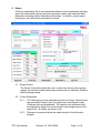
1
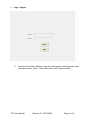
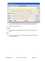
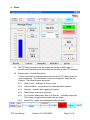
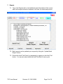
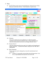
Metropolitan Computing Corporation
Process Instrumentation, Monitoring and Control
6 Great Meadow Lane, East Hanover, New Jersey 07936, U.S.A.
e-mail: [email protected] Web address: www.mcc-online.com
Tel: (973) 887-7800 Fax: (973) 887-8447
MCC
Tablet Press Controller
(TPC)
User Manual
TPC User Manual
Revision 3.2 02/01/2006
Page 1 of 18
Table of Contents
1.
Login / Logout..................................................................................................................................... 3
2.
Logout.................................................................................................................................................. 4
3.
Quit....................................................................................................................................................... 4
4.
Status................................................................................................................................................... 5
5.
Recipe .................................................................................................................................................. 7
6.
Punches............................................................................................................................................... 9
7.
Reports .............................................................................................................................................. 10
8.
Setup.................................................................................................................................................. 11
9.
Troubleshooting ............................................................................................................................... 13
10.
TPC Maintenance ......................................................................................................................... 13
11.
Glossary........................................................................................................................................ 16
12.
MCC Support ................................................................................................................................ 18
TPC User Manual
Revision 3.2 02/01/2006
Page 2 of 18
1. Login / Logout
1.1. Touch the User Name field and, using the touch-screen virtual keyboard, enter
User Name, press “enter”. Note: User name is NOT case sensitive.
TPC User Manual
Revision 3.2 02/01/2006
Page 3 of 18
1.2. Touch the Password field and, using the touch-screen virtual keyboard, type in
appropriate Password, press “enter”. Note: Password is case sensitive.
1.3. Tap on the Login bar to login.
2. Logout
2.1. Tap on the Operator box located at the top center of the Setup screen to
logout.
3. Quit
3.1. To quit the program, authorization (name and password) with a supervisor
access level is required.
TPC User Manual
Revision 3.2 02/01/2006
Page 4 of 18
4. Status
4.1. The TPC Status screen is the first screen that comes up after Login. It
provides real-time tablet press information and access to other TPC features.
4.2. Status screen - Current Information
Current information is displayed across the top of the TPC Setup screen for
user convenience. The information is stored in Recipe file, Setup file and
Reports. The following items are shown:
4.2.1.
Date & Time – displayed in 24-hour style
4.2.2.
Recipe & Batch - current recipe file name and batch number
4.2.3.
Operator - operator who logged onto system
4.2.4.
Press Mode - manual or automatic
4.2.5.
For a double sided press, Side A (or Side B) – indicates press side.
This is also a toggle switch between the two sides.
4.2.6.
Alarm ACK - alarm acknowledgement after an alarm
TPC User Manual
Revision 3.2 02/01/2006
Page 5 of 18
4.3. Average Force
The Average Force section of the TPC Setup screen displays current average
compression (kN), and, optionally, precompression (kN) and ejection (N)
forces in digital format. In addition, compression force is shown on an analog
style meter with high and low control limits indicated. Note: control limit is a
recipe parameter.
4.4. Tablet Count
The Tablet Count window displays both Good and Bad tablet count values for
the current batch. Values are updated in real time.
4.5. Tablets per Hour
The Tablets per Hour window displays the actual number of tablets being
produced by the press, each hour, based on press speed and number of
tooled stations.
4.6. Press Speed, RPM
Press speed, measured in RPM, is determined by the system proximity
switch. Both Actual and Desired values are displayed. The Desired value (on
the bottom) is changeable using the arrow buttons. It may take time for the
actual value to reach the pre-set desired speed value.
4.7. Press Control
The operator can shut down the press using the Stop Press button. The
indicator field above the button corresponds to the logical state (on/off) of the
press motor.
4.8. Dosing Control
In the Dosing Control box, the tablet press dosing cam position can be
adjusted by the user when the system is in MANUAL mode.
4.9. Feeder Speed (optional)
In the Feeder Speed, the tablet press feeder speed is displayed in digital
format. Both Desired and Actual values are displayed. The Desired value is
changeable using the arrow buttons below the digital display.
TPC User Manual
Revision 3.2 02/01/2006
Page 6 of 18
5. Recipe
A Recipe is basically a file of user-prescribed software control parameters including
upper and lower tablet rejection and press shutdown values, and individual tablet
parameters including weight, thickness and hardness. In addition, product name,
tooling type, and various user information is stored.
5.1. Recipe Control
The Recipe Control box allows the user to select from the list of the existing
recipes, as well as the ability (with proper access level) to Add New, Delete or
Modify existing recipes.
5.2. Control Parameters
5.2.1.
TPC tablet press control parameters are set in this box. Based on the
user-prescribed Target Force, the Upper and Lower Rejection and
Shutdown limits are established. The rejection and shutdown limits
are displayed in digital form at as well as in percentage based on the
target force. All values are shown in kN.
5.2.2.
Changes to numerical values are made using the Virtual Numeric
Keypad,
TPC User Manual
Revision 3.2 02/01/2006
Page 7 of 18
5.2.3.
All changes to target and limits will be used by TPC on-the-fly. That is
to say, they will be used by the controller but not stored in the Recipe.
On-the-fly changes can be made by Operator, but any changes to
Recipes can be made by Supervisor only. To apply the on-the-fly
changes, the user has to hit “Submit Changes” button.
5.2.4.
When the batch is stopped, a supervisor can store changes in the
current Recipe by touching the “Save Changes” button. To store
changes in a new Recipe, touch Add New button.
5.3. Recipe Parameters
The following entries are part of the Recipe:
5.3.1.
Target Weight is entered in mg.
5.3.2.
Target Thickness is entered in mm.
5.3.3.
Target Hardness is entered in kP.
5.3.4.
Target turret and feeder RPM can be entered in this section as well.
5.3.5.
Comments and notes such as Product Name, Product Code and other
comments can also be typed in by the user in this section for
reference.
5.4. Batch Control
5.4.1.
The Batch Control box offers options to Start Batch, limit the batch
size, or assign a Lot Number. Run Number is assigned automatically
by the computer each time you start a new Batch,
5.4.2.
Tap your finger on the Desired Batch Size space and enter a value
using the Virtual Numeric Keypad, or use the default value.
5.4.3.
To assign a Lot Number, first tap the Lot Number field, then type in the
number on the Keypad.
5.4.4.
When you tap on Start Batch button, a new batch will begin. You can
Stop Batch at any time and after that you can either Resume Batch or
Start Batch (new batch) again. When you select to Resume Batch, all
tablet counters continue from the point the batch was stopped. When
you Start Batch, all tablet counters restart from 0.
5.4.5.
When you start or resume a batch, the screen changes to Setup
screen. That means the batch is running under the current Recipe. If
you want to change Recipe, go to the Recipe screen and stop the
batch first.
TPC User Manual
Revision 3.2 02/01/2006
Page 8 of 18
6. Punches
6.1.
Tap on the Punches tab to view punch forces.
Individual punch forces are displayed on the Punch screen on bar histogram.
6.2. Forces outside the rejection limits change color to red.
TPC User Manual
Revision 3.2 02/01/2006
Page 9 of 18
7. Reports
7.1. Tap on the Reports tab to view the Batch report that makes all the current
batch and recipe information available to the user for review and printout.
7.2. Batch reports can be updated upon request by hitting the “Update Batch
Report” button.
7.3. Review the Audit Trail Event Log separately by tapping on the Audit Trail
button. You can also select historical Audit Trail files to view or print.
TPC User Manual
Revision 3.2 02/01/2006
Page 10 of 18
8. Setup
8.1. The TPC Setup screen options include Calibration, Password Control, Setup
Parameters, and other functions. A brief description is given below.
8.2. Calibration
This section displays the current calibration in a table that includes:
transducer name, transducer calibration factor, and last calibration date.
Users with maintenance level access can change calibration factors.
8.3. Password Control
Users with Supervisor authority can add, edit or delete user information and
change passwords. To exercise this feature, simply tap on the Add, Edit or
Delete button.
8.4. Setup Parameters
These parameters can be changed by a user with a maintenance level
access only.
8.4.1.
Number S of sequentially rejected tablets that will trigger alarm. If set
at 0, no rejected tablets are reported in the Audit Trail.
TPC User Manual
Revision 3.2 02/01/2006
Page 11 of 18
8.4.2.
Number R of revolutions for auto startup rejection.
8.4.3.
Number N of revolutions for average compression force calculation.
8.4.4.
Number T of rejected tablets in N revolutions that will trigger alarm.
8.4.5.
Number M of minutes of user inactivity to auto lock.
8.4.6.
Number A of revolutions to switch to control mode.
8.4.7.
Number M3 of stations that will pass under the compression rolls while
the dosing adjustment signal is active (do not change this parameter
without proper training).
8.5. Units of Measurement
Various units of measurement used in the software can be changed in the
Units of Measurement dialog box on this screen. Transducer force units can
be changed as well as tablet properties units.
8.6. Rejection Gate Delays
Rejection gate delays are viewable in the Rejection Gate Delays dialog box
shown. The delays (in terms of the number of stations) include:
8.6.1.
Between compression event and slow rejection gate.
8.6.2.
To keep slow rejection gate open after a bad tablet was encountered.
8.6.3.
Between compression event and fast rejection gate.
These parameters can be changed by a user with an MCC maintenance level
access only.
TPC User Manual
Revision 3.2 02/01/2006
Page 12 of 18
9. Troubleshooting
In case there is some software file mix-up, the user can always restore the system
to its original state (as of the latest update date) by copying the files from the
second hard drive. This Restore procedure does not affect recipe and batch files
created after the latest update date.
In case the primary hard disk has failed, the user can designate the backup disk as
the primary one. This procedure requires an expert knowledge of the computer
hardware and software and should not be attempted without proper support from
MCC or user's internal computer support group.
In all other cases, call MCC for support. MCC can establish a modem connection
and use remote software to virtually take over user's keyboard and screen. In this
case, please:
•
have modem line jack connected to a direct outgoing telephone line
(non-digital)
•
make sure MCC support personnel is available and ready to establish
connection
• from the desktop, click on the MCC support icon
Alternatively, MCC can establish an Internet connection for your TPC computer
support. Contact MCC for more information.
10. TPC Maintenance
10.1. Visual Inspection
Frequency: before each batch.
Check:
•
The integrity of the cables connecting computer, printer,
monitor, mouse, keyboard, instrument box, junction box,
transducers, balance and hardness tester.
•
The reliability of all the connections.
•
Whether the compression transducer holder is properly installed
and two 5 mm diameter holes of the compression pin are
positioned on the vertical axis.
•
Whether the locating screw and nut fasten the precompression
transducer tightly.
•
Whether the instrument box and TPC system enclosure are
locked. If not, check if there is any damage or dust inside.
10.2. Other procedures
Cleaning: after each usage (to be performed by the users).
Lubrication: as per press manual.
TPC User Manual
Revision 3.2 02/01/2006
Page 13 of 18
Transducer recalibration: annually. In addition, perform the following checks
on a weekly basis:
•
The integrity of the transducers' protection coating.
•
Visual inspection: see that there are no cracks or rust on the
transducers' surfaces. Make sure transducers are not bent.
•
See that there is no dust or powder inside the instrument box,
junction box and System enclosure.
•
See that there is no visible wiring damage of the connectors and
other components inside the instrument box, junction box and
System enclosure.
Dust filters replacement (computer cabinet enclosure): every 24 months
under normal operating conditions.
Hardware maintenance is conducted in accordance with MCC SOP # 1015
System Hardware Maintenance.
10.3. Cleaning procedures
In addition to cleaning instructions contained in the manuals for the press,
scale balance, hardness tester and original electrical equipment, cleaning of
TPC should be done by the user after each usage as follows:
•
Remove the dust and powder deposit from the electrical cabinet
and the TPC enclosure using soft brushes and vacuum cleaner.
•
Detach the ejection transducer and remove the material deposit
from its lower surface and from the adjacent surface of the
ejection plate base.
•
Make sure there is no powder deposits inside the computer
enclosure and junction box.
10.4. TPC Relocation Instructions
Preparation for transportation
TPC User Manual
•
Disconnect the cables coming from the tablet press, balance
and hardness tester.
•
Secure the cables to prevent them from damage during
transportation.
•
Disconnect the computer, monitor, printer, keyboard, mouse,
instrument box, and remove them from the mobile enclosure.
•
Make sure that the covers and doors of the computer mobile
enclosure and instrument box are tightly closed.
•
Pack separately the computer, monitor, printer, keyboard,
mouse, mobile enclosure, balance, hardness tester, instrument
box, cables and press.
•
All the components must be thoroughly secured.
Revision 3.2 02/01/2006
Page 14 of 18
Assembly after transportation
TPC User Manual
•
Check the integrity of all the components.
•
Assemble the system in accordance with appropriate project
layout drawing.
•
Be sure PC power is OFF prior to making cable connections
and powering up system.
Revision 3.2 02/01/2006
Page 15 of 18
11. Glossary
ADC
Amplifier
Calibration
Calibration Factor
Channel
Full Load
Full Scale (FS)
Hysteresis
Instrumentation
Modulation
Modulation Factor
Non-Linearity
Proximity Switch
Repeatability
TPC User Manual
Analog To Digital Converter.
A computer board that converts incoming Analog electrical signals
into Digital counts according Converter's bit resolution
Device essential for any instrumentation transducer. It is used to
provide gain (increase the output voltage level) and excitation (the
stable reference voltage) and also balance the bridge (so that the
numerical value of a baseline will be reduced effectively to zero).
Additional features of the amplifier may include filtering and shunt
calibration.
Comparison of transducer outputs at standard test loads. A line
representing a best fit to data is called a calibration graph.
A load value in engineering units that a transducer will indicate for
each volt of output, after amplifier gain and balance.
A path that interconnects the components of computer and
sensing devices, across which data and signals can be sent.
The greatest load a piece of equipment is designed to carry under
specified conditions (rated load).
The total interval over which an instrument is intended to be
operated. Also, the output from transducer when the maximum
rated stimulus is applied to the input.
The maximum difference between transducer output readings for
the same applied load. One reading is obtained by increasing the
load from zero and the other reading is obtained by decreasing the
load from Full Scale (rated) load. Measurements should be taken
as rapidly as possible to minimize creep.
Strain gauge or piezoelectric transducers installed on a tablet
press to convert force into voltage. Other types of instrumentation
measure torque, temperature, pressure, level, speed, etc.
Re: Amplitude Modulation: Modification of an amplitude of a
waveform (carrier) so that it varies in step with the instantaneous
value of another wave (signal).
In an amplitude -modulated wave, the ratio of half the difference
between the maximum and minimum amplitudes to the average
amplitude, in percent.
In Calibration: The maximum deviation of the calibration points
from a regression line (best fit to the data), expressed as a
percentage of the Full Scale (rated) output and measured on
increasing load only.
A proximity switch transducer is a non-contact electromagnetic
pickup device that senses the presence or absence of metal. It is
installed on the press in order to mark the beginning of a turret
revolution and thus enable station identification by system
software.
The maximum difference between transducer output readings for
repeated applied loads under identical loading and environmental
conditions. The ability of an instrument to give identical results in
Revision 3.2 02/01/2006
Page 16 of 18
Strain Gages
TPC - Tablet
Rejection
Controller
Transducer
Wheatstone
Bridge
TPC User Manual
successive instances.
Foil, wire or semiconductor devices that convert pressure into
electrical current. Foil gages, known for robust application range,
different nominal resistance and transverse sensitivity control, are
most commonly used for tablet press instrumentation.
A system that performs and monitor tablet rejection for tablet
presses. TPC software is monitoring and control program that
runs under the Microsoft Windows operating environment
A device that converts energy from one form to another (e.g. force
to voltage)
A special arrangement of strain gages to ensure signal balancing
and temperature sensitivity compensation
Revision 3.2 02/01/2006
Page 17 of 18
12. MCC Support
12.1. Contact MCC for support during normal working hours by any means available
below.
12.2. For modem support, special remote control software was installed. Long
distance troubleshooting, upgrades and training are just a click away. Contact
MCC to start using the modem support.
Metropolitan Computing Corporation
Process Instrumentation, Monitoring and Control
6 Great Meadow Lane, East Hanover, New Jersey 07936, U.S.A.
e-mail: [email protected]
Phone (973) 887-7800
TPC User Manual
Web address: www.mcc-online.com
Fax (973) 887-8447
Revision 3.2 02/01/2006
Page 18 of 18