1
User Manual
HTY Multifunctional scales
Manual number:
ITKU-66-01-01-11-A
MANUFACTURER OF ELECTRONIC
WEIGHING INSTRUMENTS
RADWAG Wagi Elektroniczne, 26–600 Radom Bracka 28 Street - POLAND
Phone +48 48 38 48 800, phone/fax. +48 48 385 00 10
Selling department +48 48 366 80 06
www.radwag.com
JANUARY 2011
2
Table OF CONTENTS
1. INTENDED USE ..........................................................................................................................7
2. PRECAUTIONARY MEASURES ................................................................................................7
2.1. Precautions ..........................................................................................................................7
2.2. Operation in a strong electrostatic field ................................................................................7
2.3. Scale washing ......................................................................................................................8
3. WARRANTY CONDITIONS ........................................................................................................9
4. UNPACKING AND MOUNTING................................................................................................10
5. SCALE STRUCTURE................................................................................................................11
5.1. Main dimensions ................................................................................................................11
5.2. Description of connectors...................................................................................................11
5.3. Sockets descriptions ..........................................................................................................12
6. GETTING STARTED .................................................................................................................13
7. KEYPAD OVERLAY..................................................................................................................14
8. FUNCTIONS OF KEYS .............................................................................................................14
9. PROGRAM STRUCTURE .........................................................................................................15
9.1. Main menu items ................................................................................................................15
9.1.1. Parameters ...............................................................................................................15
9.1.2. Databases .................................................................................................................16
9.1.3. Info............................................................................................................................17
9.2. Inventory of parameters .....................................................................................................17
9.2.1. Scale parameters - weighing ....................................................................................17
9.2.2. Working modes .........................................................................................................17
9.2.3. Communication .........................................................................................................20
9.2.4. Devices .....................................................................................................................21
9.2.5. Display ......................................................................................................................22
9.2.6. Inputs / Outputs ........................................................................................................23
9.2.7. Authorizations ...........................................................................................................25
9.2.8. Other .........................................................................................................................25
9.2.9. User Calibration ........................................................................................................26
10. INDICATING WINDOW ...........................................................................................................26
11. LOGGING ON..........................................................................................................................28
11.1. Logging in procedure ........................................................................................................28
11.2. Logging out procedure ......................................................................................................28
11.3. Authorization access levels...............................................................................................28
12. NAVIGATING WITHIN THE MENU .........................................................................................30
12.1. Buttons ..............................................................................................................................30
12.2. Return to weighing ............................................................................................................31
13. WEIGHING...............................................................................................................................32
13.1. Conditions of operational use ...........................................................................................32
13.2. Zeroing ..............................................................................................................................34
13.3. Tarring...............................................................................................................................34
13.4. Inscribing tare....................................................................................................................35
13.5. Weighing for dual range scales.........................................................................................35
13.6. Toggling between weight units..........................................................................................35
14. SCALE PARAMETERS...........................................................................................................36
14.1. Median filter.......................................................................................................................37
14.2. Filter ..................................................................................................................................37
14.3. Autozero ............................................................................................................................37
14.4. Minimum weight for different functions (LO) .....................................................................38
15. COMMUNICATION..................................................................................................................38
15.1. RS 232 settings.................................................................................................................39
U
3
15.2. ETHERNET setting ...........................................................................................................39
15.3. TCP protocol setting .........................................................................................................40
16. DEVICES .................................................................................................................................40
16.1. Computer ..........................................................................................................................40
16.1.1. Computer port .........................................................................................................40
16.1.2. Computer address ..................................................................................................41
16.1.3. Continuous transmission ........................................................................................41
16.1.4. Weighing printout pattern........................................................................................42
16.1.5. Cooperation with „E2R System” .............................................................................42
16.2. Printer................................................................................................................................43
16.2.1. Printer port ..............................................................................................................43
16.2.2. Printer code page ...................................................................................................44
16.2.3. Patterns for printouts ..............................................................................................44
16.3. Barcode scanner ...............................................................................................................46
16.3.1. Port for barcode scanner ........................................................................................46
16.3.2. Offset ......................................................................................................................46
16.3.3. Code length ............................................................................................................47
16.4. Transponder card reader ..................................................................................................47
16.4.1. Com port for transponder card readers ..................................................................47
16.4.2. Procedure of attributing the card number to an operator........................................48
16.5. Additional display ..............................................................................................................48
16.5.1. Additional display port.............................................................................................48
16.5.2. Communication protocol frame ...............................................................................49
17. DISPLAY..................................................................................................................................50
17.1. Text strings........................................................................................................................50
17.1.1. Display patterns ......................................................................................................51
17.1.2. Screen font .............................................................................................................52
17.1.3. Font size .................................................................................................................52
17.1.4. Bold fonts ................................................................................................................52
17.2. Function keys ....................................................................................................................53
17.3. Displaying platforms..........................................................................................................53
17.4. Bargraph type ...................................................................................................................54
17.4.1. Bargraf “Quick weighing” ........................................................................................55
17.4.2. Bargraph “Signalling checkweighing ranges” .........................................................55
18. INPUTS / OUTPUTS................................................................................................................56
18.1. Configuration of inputs ......................................................................................................56
18.2. Configuration of outputs ....................................................................................................57
19. AUTHORIZATION ...................................................................................................................58
19.1. Anonymous Operator ........................................................................................................58
19.2. Date and time ....................................................................................................................58
19.3. Printouts ............................................................................................................................59
19.4. Databases .........................................................................................................................59
19.5. Delete older data...............................................................................................................60
20. OTHER PARAMETERS ..........................................................................................................60
20.1. Languages ........................................................................................................................61
20.2. Setting date and time ........................................................................................................61
20.3. Sound signal .....................................................................................................................62
20.4. Touch panel calibration .....................................................................................................62
21. CUSTOMER CALIBRATION...................................................................................................62
21.1. Calibration procedure........................................................................................................63
21.2. Start mass adjustment ......................................................................................................65
22. SPECIAL FUNCTIONS OF WORKING MODES.....................................................................66
22.1. Recording mode ................................................................................................................67
22.2. Down-weighing .................................................................................................................67
4
22.3. Checkweighing..................................................................................................................68
22.4. Tare mode.........................................................................................................................68
22.5. Labelling mode..................................................................................................................69
22.5.1. Setting of the number of labels to print ...................................................................69
22.5.2. Setting of the number of cumulative labels to print.................................................70
22.5.3. Setting of the number of CC labels to print.............................................................70
22.5.4. Automatic triggering of cumulative labels ...............................................................70
22.5.5. Automatic triggering cumulative labels of cumulative labels...................................72
22.6. Statistics............................................................................................................................73
22.7. Automatic correction of reference mass ...........................................................................74
22.8. Minimum reference mass..................................................................................................75
23. WORK MODE - WEIGHING ....................................................................................................76
23.1. Starting the working mode ................................................................................................76
24. WORKING MODES – COUNTING PIECES............................................................................76
24.1. Starting the working mode ................................................................................................76
24.2. Setting a reference unit by entering known piece mass ...................................................77
24.3. Setting a reference unit by weighing a sample .................................................................77
24.4. Setting the reference mass by entering single piece mass directly to the database ........78
24.5. Inscribing the unit mass to the database ..........................................................................78
25. WORKING MODES – DEVIATIONS .......................................................................................79
25.1. Starting the operating mode..............................................................................................79
25.2. Reference unit mass estimated by weighing ....................................................................80
25.3. Rederence unit mass inscribing into the memory .............................................................80
26. DATABASES...........................................................................................................................80
26.1. Searching databases ........................................................................................................81
26.1.1. Quick name search.................................................................................................81
26.1.2. Quick code search ..................................................................................................82
26.1.3. Weighing date search .............................................................................................82
26.2. Adding new items in databases ........................................................................................82
26.3. Deleting items in databases ..............................................................................................83
26.4. Deleting older data ............................................................................................................83
26.5. Printing items from databases ..........................................................................................84
26.6. Export a database to a file ................................................................................................84
26.7. Database edition ...............................................................................................................85
26.7.1. Operators’ database ...............................................................................................86
26.7.2. Database of products..............................................................................................86
26.7.3. Database of Weighings / Alibi.................................................................................87
26.7.4. Database of contractors..........................................................................................88
26.7.5. Database of packages ............................................................................................89
26.7.6. Database of warehouses ........................................................................................90
26.7.7. Database of labels ..................................................................................................90
26.7.8. Database of universal variables..............................................................................91
27. COMMUNICATION PROTOCOL ............................................................................................91
27.1. General information ..........................................................................................................91
27.2. Inventory of RS commands...............................................................................................92
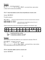
27.3. Respond message format .................................................................................................92
27.4. Command’s description ....................................................................................................93
27.4.1. Zeroing....................................................................................................................93
27.4.2. Tarring.....................................................................................................................93
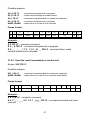
27.4.3. Get tare value .........................................................................................................94
27.4.4. Set tare value ..........................................................................................................94
27.4.5. Send the stable result in basic unit .........................................................................95
27.4.6. Send the result immediately in basic unit ...............................................................95
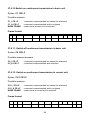
27.4.7. Send immediate results from all platforms in basic units........................................96
5
27.4.8. Send the stable result in current unit ......................................................................96
27.4.9. Send the result immediately in current unit.............................................................97
27.4.10. Switch on continuous transmission in basic unit...................................................98
27.4.11. Switch off continuous transmission in basic unit...................................................98
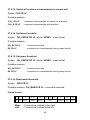
27.4.12. Switch on continuous transmission in current unit ................................................98
27.4.13. Switch off continuous transmission in current unit ................................................99
27.4.14. Set lower threshold ...............................................................................................99
27.4.15. Set upper threshold...............................................................................................99
27.4.16. Read lower threshold ............................................................................................99
27.4.17. Read upper threshold .........................................................................................100
27.4.18. Send all implemented commands.......................................................................100
27.5. Manual printouts / automatic printouts ............................................................................100
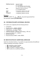
28. COOPERATION WITH EXTERNAL DEVICES .....................................................................101
29. SPECIFICATION OF ADDITIONAL MODULES ...................................................................101
29.1. Module of Analogue Outputs ..........................................................................................103
29.1.1. Technical specification ..........................................................................................103
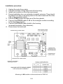
29.1.2. The way of installing inside PUE HY ...................................................................103
29.1.3. Configuration of work modes of analogue modules..............................................105
29.1.4. Connections to AN module ...................................................................................105
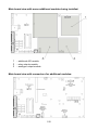
29.2. Relay module - PK1 ........................................................................................................106
29.2.1. Technical specification ..........................................................................................106
29.2.2. Installing in PUE HY indicators .............................................................................106
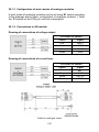
29.2.3. Drawing of cables and outputs .............................................................................108
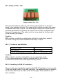
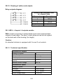
29.3. WE 4 - 4 inputs / 4 outputs module .................................................................................108
29.3.1. Technical specification ..........................................................................................108
29.3.2. Colours of cables for I/O .......................................................................................109
29.3.3. Installing method in PUE HY indicators ................................................................109
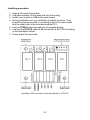
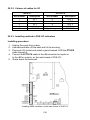
29.4. WE 8 - 8 inputs / 8 outputs module .................................................................................110
29.4.1. Technical specification ..........................................................................................110
29.4.2. Installing method in PUE HY indicators ................................................................111
29.4.3. I/O diagram ...........................................................................................................112
29.4.4. Description of input output wires...........................................................................112
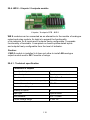
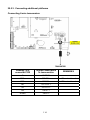
29.5. DP2 – module for an additional platform.........................................................................112
29.5.1. Technical specification ..........................................................................................113
29.5.2. Colours of wires ....................................................................................................113
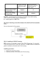
29.5.3. Connecting additional platforms ...........................................................................114
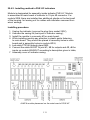
29.5.4. Installing in PUE HY housing ................................................................................116
30. DIAGRAMS OF CONNECTION CABLES.............................................................................118
31. TECHNICAL PARAMETERS ................................................................................................121
32. ERROR MESSAGES.............................................................................................................121
33. APPENDIX A – Variables for printouts...............................................................................122
33.1. Inventory of variables ......................................................................................................122
33.2. Formatting variables .......................................................................................................126
34. APPENDIX B – Functions of programmable buttons .......................................................128
35. APPENDIX C – Label pattern...............................................................................................132
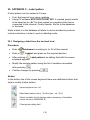
35.1. Designing a label from the terminal level ........................................................................132
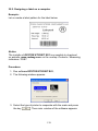
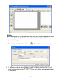
35.2. Designing a label on a computer ....................................................................................133
35.3. Saving label patterns in the scale ...................................................................................136
35.4. Attributing a label to a product ........................................................................................137
35.5. Attributing a label to a contractor ....................................................................................137
35.6. Printing labels..................................................................................................................137
36. APPENDIX D - CITIZEN printer setting...............................................................................138
37. APPENDIX E - ZEBRA printer setting ................................................................................138
38. APPENDIX F - Communication with barcode scanners ...................................................139
6
1. INTENDED USE
WPY scales are the response for the market demands concerning simplicity
of operation and high functionality. They are intended for quick and precise
weighing in industrial conditions. They are enclosed in stainless steel casings.
They can operate in high humidity and wide temperature range from -10°C
to +40°C. TFT 5.7” colour graphic displays with touch panels allows for
intuitive operation without using keys.
The standard scales is equipped with USB sockets, RS232 interfaces,
Ethernet and digital inputs-outputs 3I/3O. The device can be expanded
by connecting 3 additional weighing platforms. Additionally it can work with
barcode scanners, receipt printers, label printers, transponder card readers,
and some PC equipment (mouse, keyboard, pendrive).
2. PRECAUTIONARY MEASURES
2.1. Precautions
A. Please, read carefully this user manual before and use the device
according to its intended use;
B. Weighed loads should be placed in possibly central part of scale pan;
C. Do not clean the device with agents causing corrosion;
D. Weighing pan should be loaded with goods having gross mass lower
than maximal capacity of the scale;
E. Do not leave loads on the pan for longer period of time ;
F. In case of failure, immediately disconnect scale power supply;
G. Devices that are to be withdrawn from usage should be utilized
according to the law.
2.2. Operation in a strong electrostatic field
If the device is about to operate in a strong electrostatic field (e.g. printing
houses etc.) it should be connected to the earthing. Connect it to the
clamp terminal signed .
7
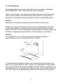
2.3. Scale washing
Weighing platforms are made of stainless steel (according to standards
PN–0H18N9, EN-1.4301, AISI–304) and silicon elements.
There is an exception, zinc coated overhead scales and painted livestock
scales made of mild constructional steel with aluminium cover plate on
the platform, polyester overlays and stainless steel or polyamide glands.
Caution:
Washing and disinfection agents should be matched to the scale.
Platforms of ramp and livestock scales as well as load-bearing structures
and weighing tracks of overhead scales can be washed with jet of water
(temp. up to +80°C) with an appropriate washing agent. Washing measuring
indicators / weighing terminals with the jet of hot water is not allowed.
Caution:
It is advisable to cover measuring indicators/weighing terminals
while washing their surrounding with the jet of water.
To wash waterproof platform scales and indicators/terminals neither jet of
water nor hot water shall be used, in order not to damage the silicon gaiter
that covers the load cell inside the platform and the overlay or glands in the
indicator/terminal. To wash pans of platform scales they should be taken off
first. Then they can be washed ether with the jet of water or by immersion.
8
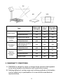
Water with
detergent
Jet of
water
Hot water
–max 80°C
Platforms with tracks
yes
yes
yes
Indicator/terminal
yes
no
no
Platform with railing
yes
yes
yes
Indicator/terminal
yes
no
no
Load bearing structure
with he load cell
yes
yes
yes
Indicator/terminal
yes
no
no
Platform
yes
no
no
Indicator/terminal
yes
no
no
Taken off pan
yes
yes
yes
Type:
Ramp scales
Livestock
scales
Overhead
scales
Platform
waterproof
scales
3. WARRANTY CONDITIONS
A. RADWAG is obliged to repair or change those elements that appears
to be faulty because of production and construction reason,
B. Defining defects of unclear origin and outlining methods of elimination
can be settled only in participation of a user and the manufacturer
representatives,
9
C. RADWAG does not take any responsibility connected with destructions
or losses derives from non-authorized or inappropriate (not adequate
to manuals) production or service procedures,
D. Warranty does not cover:
• Mechanical failures caused by inappropriate maintenance of
the device or failures of thermal or chemical origin or caused
by atmospheric discharge, overvoltage in mains or other
random event,
• Inappropriate cleaning.
E. Forfeiture of warranty appears after:
• Access by an unauthorized service,
• Intrusion into mechanical or electronic construction
of unauthorized people,
• Installing another operating system,
• Removing or destroying protection stickers.
F. The detailed warranty conditions one can find in warranty certificate.
G. Contact with the central authorized service:
+48 48 384 88 00 ext. 106 or 107.
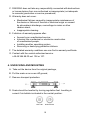
4. UNPACKING AND MOUNTING
A. Take out the device from the original package,
B. Put the scale on an even stiff ground,
C. Remove transport protection:
D. Scale should be levelled by turning regulation feet. Levelling is
correct if air bubble is situated in the central position:
10
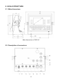
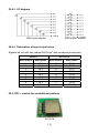
5. SCALE STRUCTURE
5.1. Main dimensions
Main dimensions of PUE HY
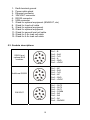
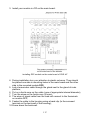
5.2. Description of connectors
11
12345678910111213-
Earth terminal ground
Power cable gland
Ethernet connector
3IN/3OUT connector
RS232 connector
USB connector
Gland for optional equipment (8IN/8OUT, etc)
Gland for Load cell cable
Gland for optional equipment
Gland for optional equipment
Gland for second load cell cable
Gland for 3-thr load cell cable
Gland for 4-thr load cell cable
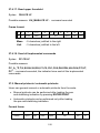
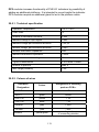
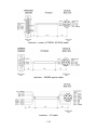
5.3. Sockets descriptions
RS232 and
optional BUS
modules
Pin1 – B
Pin2 – RxD
Pin3 – TxD
Pin4 – A
Pin5 – GND
Pin6 - +5VDC
Additional RS232
Pin1 – NC
Pin2 – RxD
Pin3 – TxD
Pin4 – NC
Pin5 – GND
Pin6 - +5VDC
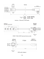
Pin1 – OUT3
Pin2 – OUT2
Pin3 – OUT1
Pin4 – COMM
Pin5 – IN3
Pin6 – IN2
Pin7 – IN1
Pin8 – GNDWE
3IN/3OUT
12
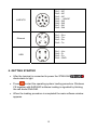
4INPUTS
Pin1 – NC
Pin2 – NC
Pin3 – NC
Pin4 – +24VDC
Pin5 – IN3
Pin6 – IN2
Pin7 – IN1
Pin8 – IN4
Ethernet
Pin1 – Rx+
Pin2 – Tx+
Pin3 – RxPin4 – Tx-
USB
Pin1 – Vcc
Pin2 – DPin3 – D+
Pin4 – GND
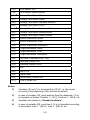
6. GETTING STARTED
• After the terminal is connected to power the STB/LOAD
diode starts to light.
• Press
to start the operating system loading procedure. Windows
CE together with RADWAG software loading is signalled by blinking
the red diode ON/LOAD.
• When the loading procedure is completed the main software window
appears.
13
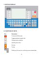
7. KEYPAD OVERLAY
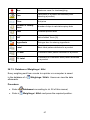
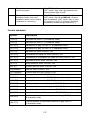
8. FUNCTIONS OF KEYS
Key
Description
Turning on/off the scale
Toggling between weight units
Changing active platform
Inscribing tare value
Zeroing
Tarring
Printing out the result or confirming some entered data
14
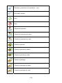
Function key (entering the menu)
Selecting products (programmable key)
Selecting contractors (programmable key)
Inscribing a tare value (programmable key)
Programmable key (free)
Programmable key (free)
Programmable key (free)
Programmable key (free)
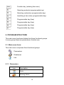
9. PROGRAM STRUCTURE
The main menu has been divided into three functional groups.
In every group there are parameters of similar use.
9.1. Main menu items
The main menu comprises three functional groups:
Parameters
Databases
Info
9.1.1. Parameters
Icon
Description
Scale
Working Modes
15
Communication
Devices
Display
Inputs / Outputs
Authorization
Other
User Calibration
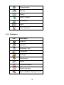
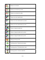
9.1.2. Databases
Icon
Description
Products
Operators
Weighings / Alibi
Contractors
Packages
Warehouses
Labels
Universal variables
Delete older data
Export database weighings to a file
16
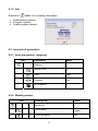
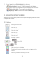
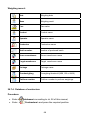
9.1.3. Info
Submenu <
Info> is for viewing information:
• Scale factory number,
• Program version,
• Scale program version.
9.2. Inventory of parameters
9.2.1. Scale parameters - weighing
Icon
Description
Value
Platform 1
-
Median Filter
0.5
Filter
Fast
Autozero
Yes
LO threshold
0
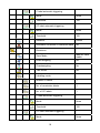
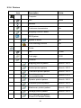
9.2.2. Working modes
Icon
Description
Value
Weighing
-
Save Mode
Manual, each
stable
Down-weighing
No
17
Checkweighing
No
Tare mode
No
Labelling mode
-
Number of labels
1
No. of cumulative labels
1
No. of CC labels
1
C label automatic triggering
-
Mode
None
Threshold
100
CC label automatic triggering
-
Mode
None
Threshold
100
Statistics
Global
Counting pieces
-
Save Mode
Manual, each
stable
Down-weighing
No
Checkweighing
No
Tare mode
No
Labelling mode
-
Number of labels
1
No. of cumulative labels
1
No. of CC labels
1
18
C label automatic triggering
-
Mode
None
Threshold
100
CC label automatic triggering
-
Mode
None
Threshold
100
Statistics
Global
Automatic correction of reference mass
No
Deviations
-
Save Mode
Manual, each
stable
Down-weighing
No
Checkweighing
No
Tare mode
No
Labelling mode
-
Number of labels
1
No. of cumulative labels
1
No. of CC labels
1
C label automatic triggering
-
Mode
None
Threshold
100
CC label automatic triggering
-
Mode
None
19
Threshold
100
Statistics
Global
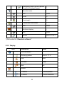
9.2.3. Communication
Icon
Description
Value
COM1
-
Baud Rate
9600
Data bits
8
Stop bits
1
Parity
None
COM2
-
Baud Rate
9600
Data bits
8
Stop bits
1
Parity
None
Ethernet
-
DHCP
No
IP Address
192.168.0.2
Subnet mask
255.255.255.0
Gateway
192.168.0.1
Tcp
-
Port
4001
20
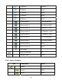
9.2.4. Devices
Icon
Description
Value
Computer
Port
None
Address
1
Continuous transmission
No
Weighing Printout Pattern
-
E2R System
-
System is active
No
Lock selecting products
No
Printer
-
Port
COM1
Code page
1250
Printouts
-
Weighing printout pattern
See ch. 16.2.3
Product printout pattern
See ch. 16.2.3
Cumulative printout pattern
See ch. 16.2.3
Cumulative printout pattern
for cumulative data
See ch. 16.2.3
Operator printout pattern
See ch. 16.2.3
Contractor printout pattern
See ch. 16.2.3
Warehouse printout pattern
See ch. 16.2.3
Package printout pattern
See ch. 16.2.3
CPG report printout pattern
(Control of Packaed Goods)
*
21
Average tare report printout pattern
(Control of Packaed Goods)
*
Barcode reader
-
Port
None
Offset
0
Code length
0
Transponder card reader
-
Port
None
Additional display
-
Port
None
Pattern
See ch. 16.2.3
*) Not related to „Standard software”.
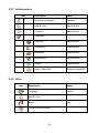
9.2.5. Display
Icon
Description
Value
Text information
-
Displaying pattern
See ch. 17.1.1
Font
Arial
Font size
Small
Bold
No
Actions
F1 Button
Choose product
F2 Button
Choose contractor
22
F3 Button
Set tare
F4 Button
None
F5 Button
None
F6 Button
None
F7 Button
None
Screen button 1
Local parameters
Screen button 2
Set MIN and MAX
Screen button 3
Statistics C: Print
Screen button 4
CCStatistics : Print
Screen button 5
C Statistics : Zero
Screen button 6
Choose package
Screen button 7
Edit batch number
Screen button 8
None
Screen button 9
None
Set Default
-
Show all platforms
No
Bargraph type
None
9.2.6. Inputs / Outputs
Icon
Description
Value
Inputs
-
Input 1
None
Input 2
None
23
Input 3
None
Input 4
None
Input 5
None
Input 6
None
Input 7
None
Input 8
None
Input 9
None
Input 10
None
Input 11
None
Input 12
None
Outputs
-
Output 1
None
Output 2
None
Output 3
None
Output 4
None
Output 5
None
Output 6
None
Output 7
None
Output 8
None
Output 9
None
Output 10
None
Output 11
None
Output 12
None
24
9.2.7. Authorizations
Icon
Description
Value
Anonymous operator
Operator
Date & Time
Administrator
Printouts
Administrator
Databases
Products
Administrator
Contractors
Administrator
Packages
Administrator
Warehouses
Administrator
Labels
Administrator
Delete older data
Advanced Operator
9.2.8. Other
Icon
Description
Value
Language
Polish
Date & Time
-
Beep
Yes
Touch screen calibration
-
25
9.2.9. User Calibration
An option only for non-verified scale
Icon
Description
Value
Platform 1
-
Setting of start mass
-
Calibration
-
10. INDICATING WINDOW
Main view:
In the main application window one can see four separate parts:
• In the top part of the window there is a status bar where a work mode,
logged-in user, time&date are displayed and active connection with a
computer are displayed.
26
• Below the status bar you can see weighing window(s).:
• There is a workspace below this window:
Notice:
The workspace is freely programmable. The default pattern is
described in ch. 17.1.1 of this manual.
• There are screen buttons below the workspace:
Notice:
1. Users can define screen function buttons. See the procedure
in ch. 17.2 of this manual;
2. The number of buttons to be defined depends on the selected
operating mode i.e.:
• In operating mode <Weighing> 9buttons are at ones disposal
displayed subsequently from 1 to 9 starting from the left side,
• In operating modes: <Counting pieces> or <Deviations> one
can define up to 7 screen buttons displayed subsequently from
1 to 7 starting from the left side. Two buttons on the right side
are attributed permanently to the modes mentioned above
because of the functions that are ascribed to them.
27
11. LOGGING ON
In order to have full access to user parameters and databases the user
should log on as an <Administrator>.
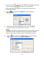
11.1. Logging in procedure
• While in the main window press <log in> on the top of the screen
and the window with operators attributed to <
Admin> will appear,
• After entering <
Admin> a screen keyboard runs with editing
window for inscribing a password,
• Type password „1111” and confirm by pressing
,
• The program returns to the main window and in the title bar you will
see <Admin> instead of <log in>.
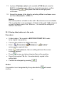
11.2. Logging out procedure
• While in the main applilcation window press the name of a logged in
operator in the top bar on the screen to open the database of operators,
• Press logging out button situated in the top bar of the operators’
database window:
• The program returns to the main window and in the top bar the
operators name is substituted by <Log in>.
11.3. Authorization access levels
Weighing software uses four access levels: administrator, advanced
operator, operator, none. Every user with any attributed access level
can perform weighings and select data from in databases to be used
during weighing.
28
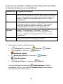
Access to user parameters, databases and working modes depending
on the authorization access level attributed:
Operator type
Access level description
None
No access to user parameters. No weighing can be confirmed.
Cannot enter the reference mass unit and estimate the reference
mase unit by weiging in „Counting Pieces” and „Deviations”. No
access to <Export the weighing database to a file> in menu
2)
<Databases> .
Operator
Access to parameters in submenu: <Weighing>, <Display>
(excluding the group <Actions>), <Others>1). Can start and
perform all weighing procedures. Access to <Export the
weighing database to a file> in menu <Databases>2).
Advanced
Operator
Access to parameters in submenus: <Weighing>, <Working
modes>, <Communication>, <Devices>1), <Display>1),
1)
<Others> . Can start and perform all weighing procedures.
Access to <Export the weighing database to a file> in menu
2)
<Databases> .
1)
Administrator
2)
Access to all user parameters, functions and databases .
Can start and perform all weighing procedures.
1. Authorization level for editing functions:
• <
Printouts> in submenu „
• <
Sample> in submenu „
Devices /
Printer”,
Devices /
Additional display”,
• <
Displaying pattern> in submenu „
Display /
Text information”,
• <
Date and Time> in submenu <
Others>,
It can be declared in submenu <
Authorizations>, which is
accessable only for users with the <Administrator> authorization
level (see ch. 19 of this manual).
29
2. A user logged in as <Administrator> in submenu
<
Authorizations> (see ch. 19 of this manual) can change
authorization levels for accessing different databases and functions
<
<
Delete older data>. The exception are database
Weighings / Alibi>, that have the status „Read only”.
12. NAVIGATING WITHIN THE MENU
Owing to the colour display with the touch panel navigating within the menu
is simple and intuitive.
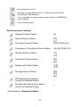
12.1. Buttons
Entering the main menu
Menu list „up”
Menu list „down”
Menu list „top”
Menu list „end”
Scrolling „up-down”
Enter (OK)
or
or
Abort
Add a new item in a database
Disabeling the formerly selected record e.g. logging out the
operator
Searching a database according to a date
30
Searching a database according to a name
Searching a database according to a code
Printing on item from a database
Clearing an editing field
Screen keyboard on / off
Reading a printout pattern from a *.lb file
(active after connecting a pendrive)
Variables for a printout pattern
or
One level up
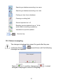
12.2. Return to weighing
The changes introduced are saved for good after they are
or
confirmed. Press
message box appears:
several times until the following
Press:
– to confirm changes or
changes. The program returns to weighing.
31
– to abort
13. WEIGHING
Put a load on the weight pan. When pictogram
indication is ready to read.
is displayed the
Notice:
A weighing can be saved after stabilising a measurement over zero
).
(pictogram
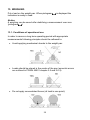
13.1. Conditions of operational use
In order to assure a long term operating period with appropriate
measurements following principles should be adhered to:
• Avoid applying mechanical shocks to the weight pan:
• Loads should be placed in the centre of the pan (eccentric errors
are outlined in PN-EN 45501 chapter 3.5 and 3.6.2):
• Do not apply concentrated forces (all load in one point):
32
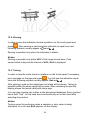
• Avoid side loads, particularly side strokes:
Special line scales should be loaded with intended loads:
• For ramp scales (hand trucks used in meat industry) the platform should
be matched to the trucks with maximum weight and the wheels were
close to the load-bearing sections:
• For livestock scales – swine, cattle:
− platforms with low railing for swine,
− platforms with high railing reinforced connecting links at the top
edge.
• For overhead scales (goods hung on hooks) adapted to underslung
tracks:
− Hooks appropriate for the track and scale,
− Smooth travelling along the load cell without jerks and movements
aside,
− Tensometer (load cell) loaded uniformly.
33
13.2. Zeroing
In order to zero the indication choose a platform on the touch panel and
. After zeroing is performed the indication is equal zero and
press
and
.
following symbols usually appear:
Zeroing is possible only when the indication is stable.
Notice:
Zeroing is possible only within ±2% of full range around zero. If the
zeroed value is beyond the interval of ±2%, Err2 is displayed.
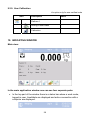
13.3. Tarring
In order to tare the scale choose a platform on the touch panel if necessary,
. You will see the indication equal
put a package on the pan and press
.
zero and following symbols usually appear: Net and
After placing a load on the weight pan net mass will be shown. Tarring is
possible within the whole range of the scale. After unloading the pan the
display shows the tarred value with minus sign.
You can also inscribe tare values to the assortment database. Every product
has a field “Tare”. In that case tare is automatically set to this value after
selecting the product.
Notice:
Tarring cannot be performer when a negative or zero value is being
displayed. In such case Err3 appears on the display.
34
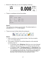
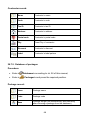
13.4. Inscribing tare
It is possible to inscribe a tare value.
Procedure:
• While in any work mode press
is displayed,
, then the screen keyboard
,
• Inscribe tare and press
• The program returns to weighing and the and the display shows
the entered value with the „–” sign provided there was zero before
on the display.
13.5. Weighing for dual range scales
Switching between the I range and the II range happens automatically
(exceeding Max of the I range).
Weighings in the second range is signalled by a pictogram in the top left
. Then weighings is done with the accuracy
corner of the display
)
of the II range to the moment of returning to zero (autozero range
where the scale switches back to the I range.
Switching between the II range and I range is automatic both in the
switching point the autozero zone. While in AUTOZERO – pictogram
appears. Then pictogram
is off and a scale returns to
weighing in the I range.
13.6. Toggling between weight units
Operators can change the weight unit in two ways:
• Pressing the unit symbol on the screen,
• Pressing formerly defined button <
Change unit>.
35
Notice:
The procedure of attributing functions to buttons is described in ch. 17.2
of this manual.
Possible selection:
•
•
•
•
•
•
gram [g]
kilogram [kg]
carat [ct]
pound [lb]
ounce [oz]
Newton [N]
14. SCALE PARAMETERS
Users can set the scale according to the ambient conditions (filtering level)
or own needs (autozero) and set the LO threshold for minimum load that
enables operation of some functions. This parameters are placed in
<
Weighing>.
In order to enter submenu <
„
Parameters /
Weighing>, press
Weighing /
and then:
Platform 1”.
Notice:
Weighing parameters are directly related to a specific weighing platform,
so at the beginning the weighing platform should be selected for which
we want to set parameters.
Inventory of scale parameters:
Median Filter
Filter
Autozero
LO Threshold
36
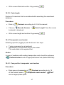
14.1. Median filter
The median filter is intended for eliminating short-lasting mechanical shocks.
Procedure:
• Enter <
<
Weighing> according to ch. 14 of the manual, select
Median Filter> and then set an appropriate value.
Accessible settings:
None - median filter is off
0.5, 1, 1.5, 2, 2.5 - filtering level to choose
14.2. Filter
This filter is intended to suppress continuous mechanical vibrations at the
cost of stabilization time.
Procedure:
• Enter <
<
Weighing> according to ch. 14 of the manual, select
Filter> and then set an appropriate value.
Accessible settings:
None, V.Fast, Fast, Average, Slow.
Notice:
The higher filtering level the longer stabilization time.
14.3. Autozero
The autozero function has been implemented in order to assure precise
indications. This function controls and corrects „0” indication.
While the function is active it compares the results continuously with
constant frequency. If two sequentional results differ less than the declared
value of autozero range, so the scale will be automatically zeroed and the
and
will be displayed.
pictograms
37
If AUTOZERO is disabled zero is not corrected automatically. However,
in particular cases, this function can disrupt the measurement process e.g.
slow pouring of liquid or powder on the weighing pan. In this case, it is
advisable to disable the autozero function.
Procedure:
• Enter <
Weighing> according to ch. 14 of the manual, select
Autozero> and then set an appropriate value.
<
Accessible settings:
NO
YES
-
Autozero off
Autozero on
14.4. Minimum weight for different functions (LO)
Parameter <LO THRESHOLD> is associated with automatic weighing.
Next weighing will not be saved until the indication goes under the
THRESHOLD LO (net).
Procedure:
Threshold Lo> according to ch. 14 of this manual
• After entering <
a keyboard is displayed,
• Inscribe LO and confirm by pressing
.
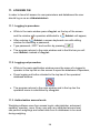
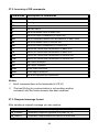
15. COMMUNICATION
The scale can communicate with external devices via different ports:
•
COM 1 (RS232),
•
COM 2 (RS232),
•
Ethernet,
•
Tcp.
The communication can be configured in parameters’ group
<
Communication>.
38
In order to enter <
„
Communication>, press
Parameters /
and then:
Communication”.
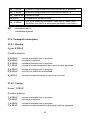
15.1. RS 232 settings
Procedure:
Communication> according to ch.15 of the manual, select
• Enter <
<
COM1> or <
COM2>, and then set an appropriate value.
For RS 232 following parameters are accessible:
•
•
•
•
Baud Rate
Data bits
Stop Bit
Parity
- 4800, 9600, 19200, 38400, 57600, 115200 bit/s
- 5, 6, 7, 8
- No, 1, 1.5, 2
- No – Odd – Even – Mark – Space
15.2. ETHERNET setting
Procedure:
• Enter <
select <
Communication> according to ch.15 of the manual,
Ethernet> and then set an appropriate value.
Following settings are accessible for Ethernet:
•
•
•
•
DHCP
IP Address
Subnet Mask
Default gateway
- Yes – No
- 192.168.0.2
- 255.255.255.0
- 192.168.0.1
Notice:
The settings above are only for information purposes. Transmission
parameters should be matched to the local client network.
• After making changes press
, then a new message is displayed:
<Restart to apply the changes>,
39
• Go back to weighing saving parameters and restart the device.
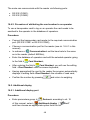
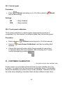
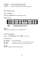
15.3. TCP protocol setting
TCP (Transmission Control Protocol) is a protocol for communication
between two computers. It operates in mode client-server. Server awaits
on connection iniciation on a specified port while client initiates connection
to the server. Scale software allows setting the port for the „Tcp” protocol.
Procedure:
Communication> parameter group as described
• Enter <
in chapter 16 of the manual,
Tcp /
Port” then you will see window <Port>
• Select: „
with the screen keyboard,
• Enter the required number and press
.
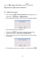
16. DEVICES
16.1. Computer
The scale can cooperate with a computer. Active connection scale-computer
is signalled by icon
in the top bar of the main window. In submenu
Computer> some settings needs to be configured for cooperation
<
with computers.
Enter submenu <
Computer>, press
„
Computer”.
Devices /
and then:
16.1.1. Computer port
Procedure:
• Enter parameters’ group <
16 of this manual,
• Select „
Computer /
Devices> according to ch.
Port” and then set the appropriate option.
40
The scale can communicate with a computer via following ports:
• RS 232 (COM1),
• RS 232 (COM2),
• Tcp.
16.1.2. Computer address
Procedure:
• Enter <
Devices> parameter group as described in chapter
16 of the manual,
Computer /
Address” then the window <Address>
• Choose „
with the screen keyboard appears,
• Enter the required address and confirm it by pressing
.
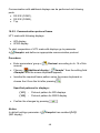
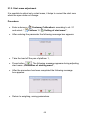
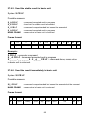
16.1.3. Continuous transmission
Users can enable continuous transmission from the scale to a computer.
Setting parameter <
Continuous transmission> starts subsequent
sending data from <
Weighing Printout Pattern> set in submenu:
„Setup /
Devices /
Computer /
Weighing Printout Pattern”.
Procedure:
• Enter parameters’ group <
manual,
Computer /
• Choose „
set an appropriate value.
Devices> according to ch. 16 of this
Continuous transmission” and then
Accessible settings:
No
Yes
-
Continuous transmission off
Continuous transmission on
41
16.1.4. Weighing printout pattern
Users in parameter <
Weighing Printout Pattern> can define variables
included in the printout from the scale to a computer.
Procedure:
• Enter <
Devices> parameter group as described in chapter
16 of the manual,
• Choose „
Computer /
Weighing Printout Pattern” then
the editing field <Weighing Printout Pattern> with the screen
keyboard appears,
• Modify the pattern if necessary and confirm the changes by pressing
.
Notice:
There are additional buttons in the bottom line of the screen keyboard.
They can be used while modifying a printout pattern.:
Screen keyboard on/off
Reading a printout pattern from a *.lb file (button active while
connecting a USB pendrive)
List of variables for printout patterns (see the list in APPENDIX A
of this manual)
Clear the editing field
16.1.5. Cooperation with „E2R System”
Scales can cooperate with computer software „E2R System” that is
a modular system for complex production supervising by monitoring
of weighings processes. In order to allow the cooperation with
„E2R System” enable parameter <
E2R System>.
Notice:
E2R System> can be activated by an authorized
The parameter <
service or the manufacturer.
42
Procedure:
• Enter <
Devices> parameter group as described in chapter
16 of the manual,
• Choose „
Computer /
E2R System /
and then set an appropriate value.
System is active”
Accessible settings:
-
No
Yes
System is not active
System is active
• If during cooperation with <
E2R System> product selection lock
is required for operators, go to parameter <
products> and set its value to <Yes>.
Lock selecting
16.2. Printer
In <
Printer> submenu users can:
• Setting communication with a printer,
• Setting code page of a printer,
• Setting patterns of printouts.
To enter <
Printer>, press
Devices /
and then: „
Parameters /
Printer”
16.2.1. Printer port
Procedure:
• Enter <
Devices> parameter group as described in chapter 16
of the manual, choose „
appropriate option.
Printer /
43
Port” and then select an
Printers can be attached to:
•
•
•
•
RS 232 (COM1),
RS 232 (COM2),
USB,
Tcp.
16.2.2. Printer code page
Procedure:
• Enter parameters <
of the manual,
Devices> as described in chapter 16
Printer /
• Choose „
will be displayed,
Code Page” then the screen keyboard
• Write the required code page and confirm by pressing
.
Notice:
The default value is 1250 – code page for Middle-East Europe.
16.2.3. Patterns for printouts
Enter <
Printouts> to define printout patterns.
Procedure:
• Enter parameter group <
Devices> as described in chapter
16 of the manual, then choose „
Printer /
Printouts”,
• After editing a pattern a memo box with the default content and the
screen keyboard,
• Modify the pattern according to your requirements and confirm it by
pressing
.
Notice:
There are additional buttons in the bottom line of the screen keyboard.
They can be used while modifying a printout pattern.:
44
Screen keyboard on/off
Reading a printout pattern from a *.lb file (button active while
connecting a USB pendrive)
List of variables for printout patterns (see the list in APPENDIX A
of this manual)
Clear the editing field
Default printouts’ settings:
Weighing Printout Pattern
{0}
Product Printout Pattern
Cumulative Printout Pattern
{50}
{51}
N={15} SUM={16}
Cumulative of Cumulative Printout Pattern
N2={20} SUM2={21}
Operator Printout Pattern
{75}
{76}
Contractor Printout Pattern
{85}
{86}
Warehouse Printout Pattern
{130}
{131}
Package Printout Pattern
{80}
{81}
{82}
CPG report printout pattern
(Control of Packaed Goods)
*
Average tare report printout pattern
(Control of Packaed Goods)
*
*) Not related to „Standard software”.
45
16.3. Barcode scanner
Cooperating with a barcode scanner allows immediate finding of the
product in the assortment database the wanted product immediately.
Configuration of communication can be configured in <
Users can set the following things:
Barcode reader>.
• Communication port for a barcode scanner,
• Offset setting (a number of characters that are omitted while reading),
• Code length (number of characters that are analysed counting from
the offset).
Notice:
Communication> set the baud rate (default 9600b/sec).
In submenu <
The detailed description of cooperation scale – barcode scanner can be
found in APPENDIX F in this manual.
16.3.1. Port for barcode scanner
Procedure:
• Enter <
„
Devices> according to ch.16 of the manual, choose
Barcode reader /
Port” and then set the appropriate value.
Barcode scanners can be connected to:
• RS 232 (COM1),
• RS 232 (COM2),
16.3.2. Offset
It outlines the first character that is significant for searching the assortment
database. All preceding characters are skipped.
Procedure:
• Enter <
Devices> according to ch.16 of the manual,
• Choose „
Barcode reader /
keyboard is displayed,
Offset” , then the screen
46
• Write a new offset and confirm it by pressing
.
16.3.3. Code length
Number of characters that is considered while searching the assortment
database.
Procedure:
• Enter <
Devices> according to ch.16 of the manual,
• Choose „
Barcode Scanner /
keyboard is displayed,
Code Length” then the screen
• Write a new length and confirm it by pressing
.
16.4. Transponder card reader
Selecting operator (logging in) can be done in two ways:
• Typing a password on a keyboard,
• Approaching a transponder card to the reader.
The card needs to be registerd first.
Notice:
In case of problems with reading transponder cards check the submenu
<
Communication> and set appropriate baud rate (default 9600b/s).
16.4.1. Com port for transponder card readers
Procedure:
• Enter group of parameters <
Devices> according to ch. 16
of this manula, select „ Transponder cards reader /
and set appropriate option.
47
Port”
The scale can communicate with the reader via following ports:
• RS 232 (COM1),
• RS 232 (COM2).
16.4.2. Procedure of attributing the card number to an operator
To use a transponder card to log on an operator the card needs to be
ascribed to the operator in the database of operators.
Procedure:
• Connect the transponder card reader to the required communication
port (RS 232 COM1 or RS 232 COM2),
• Choose a communication port for the reader (see ch. 16.4.1 in this
manual),
Communication> set the baud rate to the same
• In submenu <
as in the reader (default 9600b/s),
• Enter the database of operators and edit the selected operator going
to the field <
Card Number>,
• After entering the field <
Card Number> you will see the editing
field <Card Number> with the screen keyboard,
• Having approached the card to the reader the program automatically
displays in editing field <Card Number> the number of read card,
• Confirm the number by pressing
and return to weighing.
16.5. Additional display
16.5.1. Additional display port
Procedure:
• Enter parameters group <
Devices> according to ch. 16
Additional display /
of this manual, select „
and then choose an appropriate option from the list.
48
Port”
Communication with additional displays can be performed via following
ports:
• RS 232 (COM1),
• RS 232 (COM2),
• Tcp.
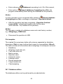
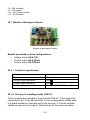
16.5.2. Communication protocol frame
HTY scale with following displays:
• WD display,
• WWG display.
To start cooperation of HTY scale with displays go to parameter
<
Sample> and define an appropriate communication protocol.
Procedure:
• Enter parameters’ group <
manual,
Devices> according to ch. 16 of this
• Choose „
Additional display /
Sample” then the editing field
<Sample> with the screen keyboard appears,
• Inscribe the required frame pattern using the screen keyboard or
choose the it from the list after pressing
.
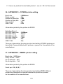
Specified patterns for displays:
{141}
-
Protocol pattern for WD displays
{142}
-
Protocol pattern for WWG display
• Confirm the changes by pressing
.
Notice:
In default settings parameter <
(WD display).
Sample> has ascribed {141}
49
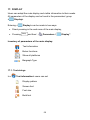
17. DISPLAY
Users can adapt the main display and visible information to their needs.
All parameters of the display can be found in the parameters’ group
Display>.
<
Entering <
Display> can be made in two ways:
• Direct pressing in the work area of the main display,
and then: „
• Pressing
Parameters /
Inventory of parameters of the main display:
Text information
Buton functions
Show all platforms
Bargraph Type
17.1. Text strings
In <
Text information> users can set:
Display pattern
Screen font
Font size
Bold font
50
Display”.
17.1.1. Display patterns
The main application window comprises a work area including information
that can be freely configured by a user.
Procedure:
• Enter <
Display> according to ch. 17 of this manual,
Text information /
Displaying pattern”, then an
• Choose: „
editing field with prompted value is displayed together with the screen
keyboard,
• Modify the pattern if necessary and confirm the changes by pressing
.
Notice:
There are additional buttons in the bottom line of the screen keyboard.
They can be used while modifying a display pattern. :
Screen keyboard on/off
Reading a display pattern from a *.lb file (button active while
connecting a USB pendrive). *.lb files with the default patterns
of display in every language version are accessible on the CD
attached to the device
List of variables for display patterns (see the list in APPENDIX A
of this manual)
Clear the editing field
Default display pattern:
Assort:
Tare:
N:
Min:
Series:
{50}
{9}{11}
{15}
{12}{10}
{14}
Pack: {80}
Sum: {16}{10}
Max: {13}{10}
51
17.1.2. Screen font
The font type can be changed in the display workspace.
Procedure:
• Enter <
Display> according to ch. 17 of this manual,
• Choose: „
type.
Text information /
Font” and set the required font
Accessible fonts:
• Arial,
• Courier.
17.1.3. Font size
Setting the font size for the workspace in the display.
Procedure:
• Enter <
Display> according to ch. 17 of this manual,
• Choose: „
font size.
Text information /
Font size and set the required
Accessible sizes:
• small,
• Average,
• Large.
17.1.4. Bold fonts
Setting bold fonts in an area of the workspace of the display.
Procedure:
• Enter <
Display> according to ch. 17 of this manual,
52
• Choose: „
Text information /
Bold” and choose a setting.
Accessible settings:
NO
YES
-
Bold is off
Bold is on
17.2. Function keys
In submenu <
Actions> users can set actions following keys:
function keys,
screen keys,
If a button has been attributed a function it has been activated at the same
time. If a button or sensor has no ascribed a function in stays inactive.
Procedure:
• Enter <
Display> according to ch. 17 of this manual,
• Choose <
Buton functions> and choose a required setting
for a choosen button: F1 - F7 or 9 screen buttons.
Notice:
The list of functions that can be attributed to keys or buttons is listed
in APPENDIX B of this manual.
17.3. Displaying platforms
If a scale is equipped with two platforms users can switch between platforms
in three ways:
• By pressing the platform number on the scale screen,
• By pressing a formerly defined button <
53
Change platform>.
• By activating in parameters all platforms that will be separately
placed in the main window of the program. In that case platforms
can be activated by pressing the area of this platform.
Notice:
The procedure of attributing functions to buttons is described in ch. 17.2
of this manual.
To activate all platforms press
„
Parameters /
appropriately.
NO
YES
-
, choose:
Show all platforms”, and set
Display /
Displaying all platforms disabled
Displaying all platforms enabled
17.4. Bargraph type
A bargraph is a typical visualisation procedure. It helps in quick weighing.
It requires less concentration to read if a weighing is between minimum
and maximum thresholds.
To see the bargraph on the screen enable it in parameters.
Procedure:
• Enter <
• Choose <
Display> according to ch. 17 of this manual,
Bargraph type> and set the required bargraph type.
Accessible bargraphs:
• Quick weighing,
• None (Bargraph is not displayed),
• Signalling checkweighing ranges.
54
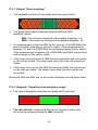
17.4.1. Bargraf “Quick weighing”
• The bargraph consists of 8 red fields and three green fields.
• The green fields signal weighings between MIN and MAX
threshold, where:
MIN = the minimum threshold of acceptable weighing - LO
MAX = the maximum threshold of acceptable weighing - HI
• If a measurement is over the MIN (to the value of 1/3 of MIN-MAX) the
green field with a triangle on the left is visible. If the measurement is
between 1/3 and 2/3 of MIN-MAX the rectangular green field is visible.
If the measurement is between 2/3 of MIN-MAX and MAX a green field
with a triangle on the right is visible.
• If the mass value is below the MIN threshold red fields with red arrows
on the left are visible. The lower mass value the more red arrows are
visible.
• If the mass value is over the MAX threshold red fields with red arrows
on the right are visible. The higher mass value the more red arrows
are visible.
Thresholds MIN and MAX are on the borders between red and green fields.
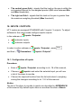
17.4.2. Bargraph “Signalling checkweighing ranges”
• This type of bargraph comprises one green and 2 red fields.
• The left red field – signals that the load on the pan is lower than
the minimum weighing threshold (Min threshold);
55
• The central green field – signals that the load on the pan is within the
set required interval for the weighed product (OK value between Min
and Max thresholds);
• The right red field – signals that the load on the pan is greater than
the maximum weighing threshold (Max threshold).
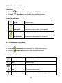
18. INPUTS / OUTPUTS
HTY scales are equipped STANDARD with 3 inputs / 3 outputs. To adjust
software to the users needs configure inputs outputs
in the submenu <
•
•
Inputs / Outputs>:
indicator inputs,
indicator outputs.
In order to enter submenu <
and then: „
Parameters /
Inputs / Outputs>, press
Inputs / Outputs”.
18.1. Configuration of inputs
Procedure:
• Enter <
Inputs / Outputs> according to ch. 18 of this manual,
• Choose <
Inputs> and enter the selected input you will see
a list of functions to ascribe,
• Choose the required function from the list and return to weighing
saving the changes according to ch. 12.2 of this manual.
Notice:
The list of functions to ascribe to inputs are described in APPENDIX B
of this manual. By default inputs have no ascribed functions <None>.
56
18.2. Configuration of outputs
Ascribing a function to the output enables the output at the same time.
If an output has no ascribed function it is disabled.
Procedure:
• Enter <
Inputs / Outputs> according to ch. 18 of this manual,
• Choose <
Outputs> and enter the required output, then you
will see the list of functions:
None
Output disabled
Stabile
Stable weighing result over LO threshold value
MIN stable
Stable weighing result below the MIN threshold
MIN non-stable
Non-stable weighing result below the MIN threshold
OK stable
Stable weighing result between MIN and MAX
thresholds
OK non-stable
Non-stable weighing result between MIN and MAX
thresholds
MAX stable
Stable weighing result over the MAX threshold
MAX non-stable
Non-stable weighing result over the MAX threshold
Confirmation of
cycle completion *
Signal that confirms that a cycle of dosing has been
completed (the defined amount)
*) Not applicable to „Standard” software.
• Choose the required function from the list and return to weighing saving
the changes according to ch. 12.2 of this manual.
Notice:
By default all outputs have no function attributed – setting <None>.
57
19. AUTHORIZATION
The submenu <
Authorization> is accessible only while being logged
in as the Administrator. In this group of parameters access levels can be
outlined.
To enter submenu <
Authorization>, press
„
Authorization”.
Parameters /
and then:
19.1. Anonymous Operator
The program allows to attribute the authorization access level to an operator
who does not perform the log-in procedure (anonymous operator).
Procedure:
•
Enter <
Authorization> according to ch. 19 of this manual,
choose <
Anonymous Operator>, and then set the
authorization access level.
Accessible authorization levels:
None, Operator, Advanced Operator, Administrator.
19.2. Date and time
Default settings allow a logged-in Administrator to change settings of date
and time. Software however allows to change the access level to this option:
Date and time>.
<
Procedure:
•
Enter parameters’ group <
Authorization> according to ch.
19 of the manual, choose <
the parameter.
Date and time>, and then set
58
Accessible authorization levels:
None, Operator, Advanced Operator, Administrator.
Notice:
Setting <None> allows free access to settings of date and time
(without the need of logging in).
19.3. Printouts
Default settings of the scale allows a logged on Administrator to edit
printout patterns. Software allows to change the access level to option
Printouts>.
<
Procedure:
•
Enter parameter group <
Authorization> according to ch. 19
of this manual, choose <
Printouts>, and set appropreately.
Access levels to printouts that can be set:
None, Operator, Advances Operator, Administrator.
Notice:
When you choose setting <None> printout patterns can be changed
even without logging on.
19.4. Databases
It is possible to set the access levels to the following databases:
•
•
•
•
•
Database of Products,
Database of Contractors,
Database of Packages,
Database of Warehouses,
Database of Labels.
59
Procedure:
•
Enter parameters’ group <
of the manual, choose <
Authorization> according to ch. 19
Databases>, and then set the parameter.
Accessible authorization levels:
None, Operator, Advanced Operator, Administrator.
Notice:
Setting <None> allows free access to settings of date and time
(without the need of logging in).
19.5. Delete older data
Default settings allow a logged-in Advanced Operator delete older data
from the <
Weighings / Alibi> database. Software however allows
to change the access level to this option: <
Delete older data>.
Procedure:
•
Enter parameters’ group <
Authorization> according to ch. 19
of the manual, choose: „
Databases /
and then set the parameter.
Delete older data”,
Accessible authorization levels:
None, Operator, Advanced Operator, Administrator.
20. OTHER PARAMETERS
There is a group of parameters different from others which influence the
operation of the scale. They are gathered in group <
language, beep etc. To enter <
„
Parameters /
Others>, press
Others”.
60
Others> e.g.
and then:
20.1. Languages
Procedure:
• Enter submenu <
choose <
Others> according to ch. 20 of this manual,
Language> and set the parameter.
Accessible languages:
•
•
•
•
•
•
•
•
Polish,
English,
German,
French,
Russian,
Spanish,
Czech,
Hungarian.
20.2. Setting date and time
Users can set date and time that are visible in the main window of the
display. Entering the edition of date and time can be made in two ways:
• Pressing the field „date and time” in the top bar of the main screen,
• Pressing button
and then: „
Parameters /
Others /
Date and Time”.
After entering the setting of date and time the screen keyboard appears.
Set year, month, day, hour, minutes and confirm by pressing
Notice:
Parameter <
Date and Time> is accessible in the scale menu
depending on the authorization access level set in the related
parameter.
61
.
20.3. Sound signal
Procedure:
• Enter <
Others> according to ch. 20 of this manual, <
and set accordingly.
Beep>
Settings:
NO
YES
- Beep disabled
- Beep enabled
20.4. Touch panel calibration
Touch panel calibration is required when inappropriate operation is
recognized. E.g. the reaction in a different place than the touching point.
Procedure:
• Enter submenu <
• Select <
appears,
Others> according to ch. 20 of this manual,
Touch Screen Calibration> and then an editing field
• Using a thin and soft pointer press (keep pressed for some time)
in the point where the cross appears, after indicating the 4th place
confirm changes by pressing
21. CUSTOMER CALIBRATION
An option only for non-verified scale
Scales require to recalculate internal divisions to more suitable ones (e.g.
g, kg etc.). In order to do this they require a calibration factor. It is adjusted
during the calibration procedure using a mass standard. Calibration should
be made when weighing a standard mass shows a different mass value.
62
To enter <
„
Customer Calibration>, press
Parameters /
and then:
Customer Calibration”.
21.1. Calibration procedure
• Enter submenu <
and select: “
Customer Calibration> according to ch. 21
Platform 1 /
Calibration”,
• After entering the parameter the following message box appears:
• Take the load off the pan of platform 1,
• Press button
. The following message appears during
adjusting start mass: „Evaluation of starting mass”,
• After the procedure has been completed the following message
box appears:
• Put calibration mass on pan of platform 1 and then select
63
,
• After the procedure of calibration factor determination following
command appears:
• Return to weighing, saving parameters.
Setting of start mass> parameter allows to adjust
<
start mass of platform 1.
Notice:
The factory calibration process for platforms 2, 3, 4 is analogical to the one
described above.
Return to weighing:
The changes introduced are saved for good after they are confirmed.
Press
several times until the following message box appears:
– to confirm changes or
Press:
changes. The program returns to weighing.
64
– to abort
21.2. Start mass adjustment
It is possible to adjust only a start mass, it helps to correct the start zero
when the span does not change.
Procedure:
• Enter submenu <
and select: “
Customer Calibration> according to ch. 21
Platform 1 /
Setting of start mass”,
• After entering the parameter the following message box appears:
• Take the load off the pan of platform 1,
• Press button
. The following message appears during adjusting
start mass: „Evaluation of starting mass”,
• After the procedure has been completed the following message
box appears:
• Return to weighing, saving parameters.
65
22. SPECIAL FUNCTIONS OF WORKING MODES
HTY scales can operate in following work modes:
Weighing
Counting pieces
Deviations
In settings of different working modes special functions that allows adopting
the operation to the customers’ needs:
Save Mode
Down-weighing
Checkweighing
Tare mode
Labelling mode
Statistics
Automatic correction of reference mass *
*) – Function operated only in <
Counting pieces>.
Work modes can be configured in <
To enter submenu <
and then: „
Working Modes>.
Working Modes>, press
Parameter /
Working Modes”.
Notice:
(local settings) in the main window of
1. First left screen button
every working mode is ascribed to access settings of current mode.
2. The change in on mode results in the same change for other working
modes working modes.
66
22.1. Recording mode
Depending on setting parameter <
from the scale to an external device.
Save Mode> users can send data
Procedure:
•
Enter parameters group <
to ch. 22 of this manual,
•
Enter the required mode and choose <
the required mode.
Working modes> according
Save Mode> then choose
Accessible options:
•
•
•
•
Manual every stable,
Manual first stable,
Automatic first stable,
Automatic last stable.
22.2. Down-weighing
Software allows to weigh in the “down-weighing” mode. It consist in putting
the load on the pan and taking off/removing portions of it with concurrent
saving weighings equal to the portions taken off the pan.
Procedure:
•
Enter parameters group <
to ch. 22 of this manual,
•
Enter the required working mode and choose <
and then set the required option.
Working Modes> according
Accessible options:
No
Yes
-
Traditional weighing
Down-weighing mode
67
Down-weighing>
22.3. Checkweighing
In case of enabling the checkweighing mode, printouts are performed only
when a weighing is between MIN and MAX thresholds that have been
defined before.
Procedure:
•
Enter parameters group <
of this manual,
•
Enter the required working mode and choose <
then set the required option.
Working Modes> according to ch. 22
Checkweighing>
Options:
No
Yes
-
Every weighing is recorded
Only weighings between MIN, MAX are recorded.
22.4. Tare mode
This function enables users to set parameters for tarring.
Procedure:
•
Enter parameters group <
of this manual,
•
Enter the required working mode and choose <
and then set the required option.
Working Modes> according to ch. 22
Tare mode>
Options:
Single
- Basic tare mode. The set (chooden) tare value is
overwritten after entering a new value
Current sum
- Summing up tare values of product and package
together with manually inscribed tare. After next setting
of product or package tare the entered tare value is
disabled
Total sum
- Summing up all subsequently entered tare values
Autotare
- Automatic tare mode together with mode <Sum of all>
68
22.5. Labelling mode
Labelling mode can be initiated together with every working mode. The
labelling system is intended to print labels for marking weighed goods e.g. a
packing process. The program can print standard labels for single products,
cumulative labels for sticking to bulk containers and cumulative labels for
cumulative labels for sticking to the large transport containers holding bulk
containers.
In submenu <
functions:
Labelling mode> there are accessible following special
Number of labels
No. of cumulative labels
No. of CC labels
C label automatic triggering
CC label automatic triggering
22.5.1. Setting of the number of labels to print
In the parameter <
Number of labels> user defines the amount
of labels. They are printed on the printer connected to the weight.
Procedure:
•
Enter parameters group <
to ch. 22 of this manual,
•
Enter the required working mode and choose: „
Working Modes> according
Labelling mode /
Number of labels” then the editing field <Number of labels>
with the screen keyboard is opened,
•
Choose the required number of labels and confirm by pressing
69
.
22.5.2. Setting of the number of cumulative labels to print
In the parameter <
No. of cumulative labels> define the amount
of sum labels. They are printed on connected printer.
Procedure:
•
Enter parameters group <
of this manual,
•
Enter the required working mode and choose: „
•
No. of cumulative labels”, then the editing field
<No. of cumulative labels> with the screen keyboard is opened,
Enter the required number od cumularive labels and confirm by
pressing
Working Modes> according to ch. 22
Labelling mode /
.
22.5.3. Setting of the number of CC labels to print
In the parameter <
No. of CC labels> define the amount of total sum
labels to print. They are printed on connected printer.
Procedure:
•
Enter parameters group <
of this manual,
•
Enter the required working mode and choose: „
•
No. of CC labels”, then the editing field <No. of CC labels>
with the screen keyboard is opened,
Enter the required number od cumularive labels and confirm
by pressing
Working Modes> according to ch. 22
Labelling mode /
.
22.5.4. Automatic triggering of cumulative labels
Users have access to the function of automatic triggering of printing
cumulative labels after setting parameters <
<
Threshold>.
70
Mode> and
Procedure:
•
Enter <
Working modes> parameter group as described
in chapter 22 of the manual,
•
Enter the required working mode and choose: „
C label automatic triggering /
required option:
None
Mass
Labelling mode /
Mode” and then set the
-
Cumulative label printout is initiated by pressing
-
or
,
Cumulative label printout is initiated by exceeding the
*
value set in parameter <
Threshold>. The value
is treated as the total from single weighings,
Number
-
Cumulative label printout is initiated by exceeding the
value set in parameter <
Threshold>. The value
is treated as the number of single weighings.
*) Manual printing of cumulative labels can be done in two ways
depending on the button used:
Printing followed by zeroing label counter or the total mass
Printing without zeroing label counter or the total mass
By default setting button
is accessible in the bottom part of the
can be done in submenu:
display but activating the button
„
Parameters /
Display /
(see ch. 17.2 of the manual).
Actions”
For automatic printout of cumulative labels counters and total mass
variables are always zeroed.
•
Confirm the changes by pressing
and go to parameter
<
Threshold> then <Threshold> window appears with the screen
keyboard,
71
•
Set the appropriate value for automatic triggering cumulative labels:
− If parameter <
Mode> is set to <Mass> then enter the required
value of total mass to exceed in order to print the C label,
− If parameter <
Mode> is set to <Number> use the screen
keyboard to enter the required counter value as a threshold to
trigger off printing C labels.
• Confirm the changes introduced by pressing
.
22.5.5. Automatic triggering cumulative labels of cumulative labels
Users have access to the function of automatic triggering of printing
cumulative labels of cumulative labels after setting parameters
Mode> and <
<
Threshold>.
Procedure:
•
Enter <
Working modes> parameter group as described
in chapter 22 of the manual,
•
Enter the required working mode and choose: „
Mode” and then set the
CC label automatic triggering /
required option:
None
-
Cumulative label of cumulative labels printout is initiated
by pressing
Mass
-
Labelling mode /
or
*
,
Cumulative label of cumulative labels printout is initiated by
exceeding the value set in parameter <
Threshold>.
The value is treated as the total from single weighings,
Number
-
Cumulative label of cumulative labels printout is initiated by
exceeding the value set in parameter <
Threshold>.
The value is treated as the number of single weighings,
*) Manual printing of cumulative labels can be done in two ways depending
on the button used:
72
Printing followed by zeroing label counter or the total mass
Printing without zeroing label counter or the total mass
By default setting button
is accessible in the bottom part of the
can be done in submenu:
display but activating the button
„
Parameters /
Actions” (see ch. 17.2).
Display /
For automatic printout cumulative labels of cumulative (CC)
labels counters and total mass variables are always zeroed.
•
Confirm the changes by pressing
and go to parameter
<
Threshold> then <Threshold> window appears with
the screen keyboard,
•
Set the appropriate value for automatic triggering CC labels:
− If parameter <
Mode> is set to <Mass> then enter the required
value of total mass to exceed in order to print the CC label,
− If parameter <
Mode> is set to <Number> use the screen
keyboard to enter the required counter value as a threshold to
trigger off printing CC labels.
• Confirm the changes introduced by pressing
.
22.6. Statistics
All statistics are continuously updated after each measurement is saved
in the scale memory. Statistics can be calculated globally (does not depend
on the selected product) or separately for every product from the assortment
database. It can be set in parameters <
Statistics>.
Procedure:
•
Enter <
Working modes> parameter group as described
in chapter 22 of the manual,
73
•
Enter the required working mode and choose <
and then set the required option.
Statistics>
Options:
Global
Product
-
global statistics,
statistics for every product.
Notice:
Statistics> set to <Product> bare in mind
In case of operation with <
that after restarting only statisics of the last weighed product are recovered.
22.7. Automatic correction of reference mass
<
Working mode <
It concerns the
Counting pieces> working mode
Counting Pieces> comprises a special function
<
Automatic correction of reference mass>, that can be used for
correcting the unit mass <SMP>.
To enable the function in parameters you need to:
• Enter parameter group <
Working modes> according to ch.
22 of this manual, choose: „
Counting Pieces /
Automatic
correction of reference mass” and set appropriate option.
Options:
No
Yes
Function <
-
Automatic correction of reference mass disabled
Automatic correction of reference mass enabled
Automatic correction of reference mass> in mode
Counting Pieces> is enabled at the moment of estimating the sample
<
quantity and signalled by displaying <PCS> and <SMP> (single piece mass)
on the top part of the display.
74
There are four criteris of working “Automatic correction of reference
mass” function:
1. equilibrium should be reached,
2. quantity of pieces should be increased,
3. added quantity of pieces should not be greater than double
number of pieces on the pan,
4. the new sample can be different from the old sample by ± 0.3
of pcs (absolute value),
If a user recognises that the sample quantity is adequate the unit mass
(single piece mass) can be saved (see ch. 24.5 of this manual)
and disable the function by pressing ENTER/PRINT.
Notice:
While the function is active ENTER/PRINT changes its functionality.
Pressing ENTER/PRINT does not result in printing and saving weighings.
22.8. Minimum reference mass
<
It concerns the
Counting pieces> working mode
Users before beginning the procedure of single piese mass evaluation can
declare “minimum reference mass” i.e. minimum total weight of all pieces
put on the scale pan expressed in reading divisions.
Procedure:
• Enter parameter group <
22 of this manual,
Working modes> according to ch.
Counting pieces /
• Choose „
and then set an appropriate value.
Minimum reference mass”
Accessible settings: 1 d, 2 d, 5 d, 10 d.
Notice:
While the procedure of evaluation the mass of single piece the the mass
of all pieces put on the pan is lower than the value declared in parameter
Minimum reference mass”, the following warning message will
„
be displayed: < Too low sample mass>.
75
23. WORK MODE - WEIGHING
The <
Weighing> mode is the standard working mode allowing to
perform weighings and saving them in the database <
Weighings / Alibi>.
23.1. Starting the working mode
The <
Weighing> mode is the standard working mode. If a user
has changed the operating mode to another follow the actions below:
• While in the main window press the icon with mode name placed on
the top bar on the left then submenu comprising all accessible working
modes <Working Modes> opens,
• Choose <
Weighing>, program automatically returns to the main
window displaying icon
in the top bar.
24. WORKING MODES – COUNTING PIECES
Counting pieces is work mode allowing to count pieces on the basis of the
standard unit mass of a single piece set on the scale or fetched from the
database.
Notice:
If counting pieces is performed in an additional container it should be tarred.
24.1. Starting the working mode
Procedure:
• While in the main window press
in the top bar, then you will
see a submenu <Working Modes> comprising a list of modes,
• Choose <
Counting Pieces>, program automatically returns
to the main window displaying icon
76
in the top bar,
• The weight unit is automatically changed to „pcs” and two screen
buttons on the right side appear:
Enter piece mass
Estimate piece mass
24.2. Setting a reference unit by entering known piece mass
Procedure:
• Enter mode <
of this manual,
Counting Pieces> according to ch. 24.1
(enter piece mass), then an editing field is displayed
• Press
<Reference Unit> with the screen keyboard,
• Enter a value and confirm it by pressing
<
, which causes starting
Counting Pieces> with automatic setting the reference unit.
Notice:
1. In case of entering a reference unit higher then the maximum weighing
range of the main scale the program will display a message box:
<Value too high>,
2. In case of entering the single piece mass lower than 0.1 d, the
program will display a message box: <Value to small>.
24.3. Setting a reference unit by weighing a sample
Procedure:
• Enter mode <
of this manual,
Counting Pieces> according to ch. 24.1
• If pieces are weighed in a container it needs to be put on the pan
and tarred,
(estimate piece mass), then the editing field is displayed
• Press
<Reference Quantity> together with the screen keyboard,
77
• Enter a value and confirm it by pressing
, then the following
message is displayed: <Put pieces: xx> (where xx – the value
entered before),
• Put the declared quantity of pieces on the pan and when the result
) confirm it by pressing
.
is stable (symbol
• The program automatically calculates reference unit mass and
causes starting <
Counting Pieces>.
Notice:
• The total mass of all pieces put on the weight pan cannot be greater
than the weighing range;
• The total mass of all pieves put on the weight pan cannot be less than
the value declared in parameter „Minimum reference mass” (see
section 22.8). If the condition above is not fulfilled the scale dispalays
the message <Too low sample mass>;
• The mass of one unit may not be less than 0.1 of reading division
of the scale. If this condition is not fulfilled the scale dispalays the
message: <Too low piece mass>.
24.4. Setting the reference mass by entering single piece mass directly
to the database
After selecting a product from the assortment database a mass of single
piece from the field <Mass> is used.
Procedure:
• While in <
• Using
Counting Pieces> press
or
,
choose a product and confirm it by pressing
Notice:
The selected product has to have declared unit mass (single piece mass).
24.5. Inscribing the unit mass to the database
The unit mass can be described a unit mass the following way:
78
.
a) Estimate the unit mass (see 24.2 and 24.3),
b) Enter the products database
,
c) Keep the finger pressed on the required position then a context
menu is displayed,
d) Choose option <Ascribe standard>, then the standard unit mass
is attributed to the product in the field <Mass>.
Notice:
Attributing a standard to a selected product is also possible by
programmable button. Setting programmable buttons is described in ch.
17.2 of this manual The list of functions is described in APPENDIX B
of this manual.
25. WORKING MODES – DEVIATIONS
The program allows to check weighings in deviations (in %) around an
outlined standard mass. The standard mass can be outlined by weighing
or entering it by a user.
25.1. Starting the operating mode
Procedure:
• While in the main window press
in the top bar of the window then
you will see a submenu <Working Modes> comprising a list of modes,
• Choose mode <
Deviations>, the program will automatically
returns to the main window displaying icon
in the top bar,
• The weight unit is automatically changed to „%” and two screen
buttons on the right side appear:
Enter reference mass
Estimate reference mass
79
25.2. Reference unit mass estimated by weighing
Procedure:
• Enter <
Deviations> according to ch. 25.1 of this manual,
• If the standard is to be weighed in a container, the container needs
to be put on the pan and tarred,
(Estimate standard mass), then a message is displayed:
• Press
<Put standard>,
• Put the load on the pan. After stabilization the result is taken as
a standard (symbol
). Confirm it by pressing
,
• At the same time the weight unit is changed to (w %).
25.3. Rederence unit mass inscribing into the memory
Procedure:
• Enter <
Deviations> according to ch. 25.1 of this manual,
• Press
(Give piece mass), then an editing field is displayed
<Give piece mass> together with the screen keyboard,
• Enter a value and confirm by pressing
,
• At the same time the weight unit is changed to (w %).
26. DATABASES
HTY databases hold different data:
Products
Operators
Weighings / Alibi
Contractors
80
Packages
Warehouses
Labels
Universal variables
In order to enter <
<
Databases>, press
and choose
Databases>.
26.1. Searching databases
Users can quickly search databases according to the following criteria:
•
Name,
•
Code.
The quick search according to the criteria above is applicable for databases
of: operators, products, contractors, packages, warehouses and labels.
Additionally users can search the weighing database according to <
weighing date>.
26.1.1. Quick name search
Procedure:
• Enter <
• Enter <
Databases> according to ch. 26 of the manual,
Products>,
• Press
, then an editing field appears <Search by name>
with the screen keyboard,
• Inscribe the name of a product or its part and press
• The program will automatically edit the required product.
81
.
26.1.2. Quick code search
Procedure:
• Enter <
• Enter <
Databases> according to ch. 26 of the manual,
Products>,
• Press
, then an editing field appears <Search by code>
with the screen keyboard,
• Inscribe the name of a product or its part and press
.
• The program will automatically edit the required product.
26.1.3. Weighing date search
Procedure:
• Enter <
Databases> according to ch. 26 of the manual,
• Enter <
Weighings>,
• Press
, then an editing field appears <Specify year>
with the screen keyboard,
• Inscribe: year, month, day, hour, minute of weighing and confirm
it by pressing
.
• The program will automatically display the list of weighings putting
at the top the position with the entered date.
26.2. Adding new items in databases
Procedure:
• Enter <
Databases> according to ch. 26 of this manual,
• Enter database <
• Press
Products>,
, then the message is displayed: <Create new record?>,
• Confirm it by pressing
edition of new record.
, the program automatically enters
82
Notice:
Adding new records in databases is possible only by logged-in
administrators. It does not concern the database of weighings.
26.3. Deleting items in databases
Procedure:
• Enter <
• Enter <
Databases> according to ch. 26 of the manual,
Products>,
• Give a long press to the item, then the context menu is displayed,
• Press <Delete>, then a message is displayed:
<Are you sure you want to delete?>,
• Confirm it by pressing
.
Caution:
Deleting records in databases is possible only by logged-in administrators.
It does not concern the database of weighings.
26.4. Deleting older data
A user after logging on as administrator can delete older position
in the database of weinghings <
Weighing / Alibi>.
Caution:
Factory settings prevent users from deleting weighings that are up to
one year old. Because of incompatible regulations in different countries
concerning the time of protecting data this period can be modified by
distributors.
Procedure:
• Enter the submenu <
Databases> according to ch. 26 of the manual,
Delete older data>, then an editing field is displayed
• Enter <
<Give year> with the screen keyboard,
83
• Give a date before which data need to be removed and confirm
it by pressing
,
Caution:
If a user enters a date from the protected period the program displays
a message box: <Wrong value>.
• After entering a date beside protected period the program displays
a message box: <Are you sure you want to delete?>,
the program will start removing data
• After it is confirmed by
and after completing it displays the number of deleted records,
• Press
to leave.
26.5. Printing items from databases
Users can print any record in databases.
Procedure:
• Enter the submenu <
• Enter <
Databases> according to ch. 26 of the manual,
Products> and press the required item,
• After editing the required record press
in the top bar of the display,
• If a printer is connected information about the selected product
is printed.
Notice:
Default printout patterns for printing records from different databases
are described in ch. 16.2.3 of this manual.
26.6. Export a database to a file
An operator after a series of weighings can export a database to a file
using a pendrive.
Procedure:
• Connect a pendrive to USB,
84
• Enter submenu <
Databases> according to ch. 26 of this manual,
• Enter option <
Export database of weighings to a file>, the
program automatically starts saving the database on the pendrive,
Notice:
Export database
In case a pendrive is not recognized after entering <
of weighings to a file> a message is displayed: <Operation failed>.
• After the operation has been completed: „Operation finished
successfully” is displayed together with the file name
(with extention *.txt) created on the pendrive,
Notice:
The file name consists of a database name and scale factory number,
e.g. <Weighings_239800.txt>.
• Disconnect the pendrive to USB.
File template:
The created file comprises a table with columns separated by tabulation
characters <Tab> in case to allow direct export to a spreadsheet <Excel>.
The table includes all informations about weighings in subsequent columns:
•
•
•
•
•
•
•
•
•
•
Date&time,
Weighing result with unit,
Tare value with unit,
Batch number,
Operator name,
Contractor name,
Package name,
Source warehouse,
Target warehouse,
Checkweighing.
26.7. Database edition
The database edition can be performed by an administrator.
85
26.7.1. Operators’ database
Procedure:
• Enter <
Databases> according to ch. 26 of this manual,
• Enter <
Operators> and press the required position.
Record of operator:
Name
Operator name
Code
Operator code
Password
Password to log on (max. 16 characters)
Access level
Authorization access level
Card number
Transponder card reader for logging on
26.7.2. Database of products
Procedure:
• Enter <
• Enter <
Databases> according to ch. 26 of this manual,
Products>and press the required position.
Product record:
Name
Product name
Code
Product code
EAN code
Product barcode
Mass
Nominal product mass
Min
Minimum mass for checkweighing
86
Max
Maximum mass for checkweighing
Tare
Tare value (it is preset automatically after
selecting a product)
Price
Unit price
Number of validity
dates
Number of days to calculate expiery date
Date
Constant product date
VAT
Value Added Tax in [%]
Ingredients
Dialogue box for entering ingredients
Label
Basic label pattern attributed to a product
C Label
Cumulative label pattern attributed to a product
CC Label
Cumulative of cumulative label pattern attributed
to a product
26.7.3. Database of Weighings / Alibi
Every weighing sent from a scale to a printer or a computer is saved
in the database of <
afterwards.
Weighings / Alibi>. Users can view the data
Procedure:
• Enter <
Databases> according to ch. 26 of this manual,
• Enter <
Weighings / Alibi> and press the required position.
87
Weighing record:
Date
Weighing date
Mass
Weighing result
Tare
Tare value
Product
Product name
Operator
Operator name
Contractor
Contractors name
Batch number
Number of produced batch
Source warehouse
Source warehouse name
Target warehouse
Target warehouse name
Package
Package name
Checkweighing
A weighing threshold (MIN, OK or MAX)
Platform number
Platform number to perform weighings
26.7.4. Database of contractors
Procedure:
• Enter <
• Enter <
Databases> according to ch. 26 of this manual,
Contractors> and press the required position.
88
Contractor record:
Name
Contractor’s name
Code
Contractor’s code
Tax ID
Contractor’s tax ID
Address
Contractor’s address
Postal code
Contractor’s postal code
City
Town/City of contractor
Discount
Contractor’s discount
Label
Contractor’s label pattern
26.7.5. Database of packages
Procedure:
• Enter <
Databases> according to ch. 26 of this manual,
• Enter <
Packages> and press the required position.
Package record:
Name
Package name
Code
Package code
Mass
Package weight (set automatically after choosing
after choosing a package from the database)
89
26.7.6. Database of warehouses
Procedure:
• Enter <
Databases> according to ch. 26 of this manual,
• Enter <
Warehouses> and press the required position.
Warehouse record:
Name
Warehouse name
Code
Warehouse code
Description
Additional warehouse description
26.7.7. Database of labels
The database comprises patterns of labels which users can attribute
to products or contractors to operate in labelling mode.
Procedure of editing databases:
• Enter <
• Enter <
Databases> according to ch. 26 of this manual,
Labels> and press the required position.
Label record:
*)
Name
Label name
Code
Label code
Label pattern*
Label printout pattern
Ways of designing and sending patterns to a scale can be found
in APPENDIX C of this manual.
90
26.7.8. Database of universal variables
The database include patterns of general purpose variables which users can
,
,
attribute to screen function buttons
any alphanumeric text intended to be printed.
,
,
in order to enter
Notice:
The procedure of attributing functions to buttons is described in ch. 17.2
of this manual.
Procedure of editing databases:
• Enter <
• Enter <
Databases> according to ch. 26 of this manual,
Universal variables> and press the required position.
Universal variable record:
Code
Universal variable code
Value to pay
Universal variable value intended to be printed
27. COMMUNICATION PROTOCOL
27.1. General information
A. A character protocol scale-terminal has been designed for
communication between RADWAG scales and external devices
via RS-232 interface.
B. It consists of commands sent from an external device to the scale
and a responses from a scale.
C. Responses are sent every time after receiving a command
(reaction for any command).
D. Using commands allows users to receive some information about
the state of scale and/or influence the operation e.g.: Requesting
weighing results, display control.
91
27.2. Inventory of RS commands
Commands
Description of commands
Z
Zeroing
T
Tarring
OT
Get tare value
UT
Set tare value
S
Send the stable result in basic unit
SI
Send the result immediately in basic unit
SIA
Send immediate results from all platforms in basic units
SU
Send the stable result in current unit
SUI
Send the result immediately in current unit
C1
Switch on continuous transmission in basic unit
C0
Switch off continuous transmission in basic unit
CU1
Switch on continuous transmission in current unit
CU0
Switch off continuous transmission in current unit
DH
Set lower threshold
UH
Set upper threshold
ODH
Read lower threshold
OUH
Read upper threshold
PC
Send all implemented commands
Notice:
1. Each command have to be terminated in CR LF;
2. The best Policy for communication is not sending another
command until the former answer has been received.
27.3. Respond message format
After sending a request message you can receive:
XX_A CR LF
command accepted and in progress
XX_D CR LF
command completed (appears only after XX_A)
XX_I CR LF
command comprehended but cannot be executed
92
XX _ ^ CR LF
command comprehended but time overflow error appeared
XX _ v CR LF
command comprehended but the indication below the
XX _ OK CR LF
Command done
ES_CR LF
Command not comprehended
XX _ E CR LF
error while executing command – time limit for stable result
exceeded (limit time is a descriptive parameter of the scale)
XX
_
- command name
- substitutes spaces
27.4. Command’s description
27.4.1. Zeroing
Syntax Z CR LF
Possible answers:
Z_A CR LF
Z_D CR LF
- command accepted and in progress
- command completed
Z_A CR LF
Z_^ CR LF
- command accepted and in progress
- command comprehended but zero range overflow appeared
Z_A CR LF
Z_E CR LF
- command accepted and in progress
- time limit for stable result exceeded
Z_I CR LF
- command comprehended but cannot be executed
27.4.2. Tarring
Syntax: T CR LF
Possible answers:
T_A CR LF
T_D CR LF
- command accepted and in progress
- command completed
T_A CR LF
T_v CR LF
- command accepted and in progress
- command comprehended but tare range overflow appeared
93
T_A CR LF
T_E CR LF
- command accepted and in progress
- time limit for stable result exceeded
T_I CR LF
- command comprehended but cannot be executed
27.4.3. Get tare value
Syntax: OT CR LF
Reply: OT_TARA CR LF – command executed
Frame format:
1
2
3
4-12
13
O
T
space
tare
space
Tare
Unit
-
14
15
16
unit
17
18
19
space
CR
LF
9 characters justified to the right
3 characters justified to the left
Notice:
Tare values are always send in calibration unit.
27.4.4. Set tare value
Syntax: UT_TARE CR LF, where TARE – tare value
Possible replies:
UT_OK CR LF
- command completed
UT_I CR LF
- command correct, but not accessible at the moment
ES CR LF
- command incorrect (e.g. incorrect tare format)
Notice:
Use dots as decimal points in tare values.
94
27.4.5. Send the stable result in basic unit
Syntax: S CR LF
Possible answers:
S_A CR LF
S_E CR LF
- command accepted and in progress
- time limit for stable result exceeded
S_I CR LF
- command comprehended but cannot be executed
S_A CR LF
MASS FRAME
- command accepted and in progress
- mass value in basic unit is returned
Frame format:
1
2-3
4
5
6
7-15
16
S
space
stability
space
sign
mass
space
17
18
19
unit
20
21
CR
LF
Example:
S CR LF – computer command
S _ A CR LF - command accepted and in progress
S _ _ _ _ - _ _ _ _ _ _ 8 . 5 _ g _ _ CR LF – command done, mass value
in basic unit is returned.
27.4.6. Send the result immediately in basic unit
Syntax: SI CR LF
Possible answers:
SI_I CR LF
- command comprehended but cannot be executed at the moment
MASS FRAME
- mass value in basic unit is returned
Frame format:
1
2
3
4
5
6
7-15
16
S
I
space
stability
space
sign
mass
space
95
17
18
unit
19
20
21
CR
LF
Example:
S I CR LF – computer command
S I _ ? _ _ _ _ _ _ _ 1 8 . 5 _ k g _ CR LF - command done, mass value
in basic unit is returned immediately.
27.4.7. Send immediate results from all platforms in basic units
Syntax: SIA CR LF
Possible answers:
- command comprehended but cannot be executed at the moment
SIA_I CR LF
MASS FRAME „P1” CR LF
MASS FRAME „P2” CR LF - mass values are immediately returned from all
platforms in basic units
Frame format with mass from subsequent platforms as indicator reply:
1
2
3
4
5
6
7-15
16
P
n
space
stability
space
sign
mass
space
17
18
unit
19
20
21
CR
LF
n
- weighing platform number
mass - 9 characters justified to the right
unit - 3 characters justified to the left
Example:
Let us assume that both platforms are connected to indicator PUE HY.
S I A CR LF – computer command
P 1 _ ? _ _ _ _ _ _ 1 1 8 . 5 _ g _ _ CR LF
P 2 _ _ _ _ _ _ _ _ _ 3 6 . 2 _ k g _ CR LF - command done, mass values
from both platforms are returned in basic units
27.4.8. Send the stable result in current unit
Syntax: SU CR LF
96
Possible answers:
SU_A CR LF
SU_E CR LF
- command accepted and in progress
- timeout while waiting for stable results
SU_I CR LF
- command comprehended but cannot be executed
SU_A CR LF
MASS FRAME
- command accepted and in progress
- mass value in current unit is returned
Frame format:
1
2
3
4
5
6
7-15
16
S
U
space
stability
space
sign
mass
space
17
18
19
unit
20
21
CR
LF
Example:
S U CR LF – computer command
S U _ A CR LF - command accepted and in progress
S U _ _ _ - _ _ 1 7 2 . 1 3 5 _ N _ _ CR LF - command done, mass
value in current unit is returned.
27.4.9. Send the result immediately in current unit
Syntax: SUI CR LF
Possible answers:
SUI_I CR LF
- command comprehended but cannot be executed
MASS FRAME
- mass value in current unit is returned immediately
Frame format:
1
2
3
4
5
6
7-15
16
S
U
I
stability
space
sign
mass
space
17
18
unit
19
20
21
CR
LF
Example:
S U I CR LF – computer command
S U I ? _ - _ _ _ 5 8 . 2 3 7 _ k g _ CR LF - command executed and mass
returned
97
27.4.10. Switch on continuous transmission in basic unit
Syntax: C1 CR LF
Possible answers:
C1_I CR LF
- command comprehended but cannot be executed
C1_A CR LF
MASS FRAME
- command comprehended and in progress
- mass value in basic unit is returned
Frame format:
1
2
3
4
5
6
7-15
16
S
I
space
stability
space
sign
mass
space
17
18
19
unit
20
21
CR
LF
20
21
CR
LF
27.4.11. Switch off continuous transmission in basic unit
Syntax: C0 CR LF
Possible answers answers:
C0_I CR LF
- command comprehended but cannot be executed
C0_A CR LF
- command comprehended and executed
27.4.12. Switch on continuous transmission in current unit
Syntax: CU1 CR LF
Possible answers:
CU1_I CR LF
- command comprehended but cannot be executed
CU1_A CR LF
MASS FRAME
- command comprehended and in progress
- mass value in current unit is returned
Frame format:
1
2
3
4
5
6
7-15
16
S
U
I
stability
space
sign
mass
space
98
17
18
unit
19
27.4.13. Switch off continuous transmission in current unit
Syntax: CU0 CR LF
Possible answers:
CU0_I CR LF
- command comprehended but cannot be executed
CU0_A CR LF
- command comprehended and executed
27.4.14. Set lower threshold
Syntax: DH_XXXXX CR LF, where: XXXXX – mass format
Possible answers:
DH_OK CR LF
- command executed
ES CR LF
- command not comprehended (wrong mass format)
27.4.15. Set upper threshold
Syntax: UH_XXXXX CR LF, where: XXXXX – mass format
Possible answers:
UH_OK CR LF
- command executed
ES CR LF
- command not comprehended (wrong mass format)
27.4.16. Read lower threshold
Syntax: ODH CR LF
Possible answers: DH_MASA CR LF - command executed
Frame format:
1
2
3
4-12
13
D
H
space
mass
space
Mass
Unit
14
15
16
unit
- 9 characters justified to the right
- 3 characters justified to the left
99
17
18
19
space
CR
LF
27.4.17. Read upper threshold
Syntax: OUH CR LF
Possible answers: UH_MASA CR LF - command executed
Frame format:
1
2
3
4-12
13
U
H
space
mass
space
Mass
Unit
14
15
16
unit
17
18
19
space
CR
LF
- 9 characters justified to the right
- 3 characters justified to the left
27.4.18. Send all implemented commands
Syntax: PC CR LF
Possible answers:
PC_A_”Z,T,S,SI,SIA,SU,SUI,C1,C0,CU1,CU0,DH,ODH,UH,OUH,OT,UT,
PC" – command executed, the indicator have sent all the implemented
commands.
27.5. Manual printouts / automatic printouts
Users can general manual or automatic printouts from the scale.
• Manual printouts can be performed after loading the pan
and stabilizing indication by pressing ENTER/PRINT.
• Automatic printouts can be performed only after loading
the pan and stabilizing indication.
Format frame:
1
2
3
4 -12
13
stability
space
sign
mass
space
100
14
15
unit
16
17
18
CR
LF
Stability character
[space] if stable
[?] if not stable
[^] if an indication over the range
[v] if fan indication below the range
sign
[space] for positive values or
[-] for negative values
9 characters justified to the right
3 characters justified to the left
3 characters justified to the left
mass
unit
command
Example:
_ _ _ _ _ _ 1 8 3 2 . 0 _ g _ _ CR LF – the printout generated from
the scale after pressing ENTER/PRINT.
28. COOPERATION WITH EXTERNAL DEVICES
HTY scales can cooperate with the following devices:
•
•
•
•
•
•
•
•
Computers,
Receipt printer - KAFKA, EPSON,
Label printer - CITIZEN, ZEBRA,
Transponder card reader - CK-01,
Additional display in stainless steel casing - WD- 4/3,
Large size display (2”) - WWG-2,
Barcode scanner,
External buttons PRINT, TARA, ZERO.
29. SPECIFICATION OF ADDITIONAL MODULES
Apart from standard interface, it is possible to equip terminals with additional
module increasing functionality of devices:
•
•
•
•
AN - analogue outputs module,
PK 1 - relay outputs module,
WE 8 - 8 inputs / 8 outputs module,
DP-2 module for an additional platform.
101
Main board view with some additional modules being installed:
1
2
3
- additional A/D module,
- relay outputs module,
- analogue output module.
Main board view with connectors for additional modules:
102
J3 – WE 8 module
J3 – AN module
J10 – PK1 Relay module
J11 – DP2 module
29.1. Module of Analogue Outputs
Module of analogue outputs
Module accessible in three configurations:
•
•
•
Voltage output AN 0-10V
Current output AN 4-20mA
Current output AN 0-20mA
29.1.1. Technical specification
Work modes
4 - 20mA , 0 - 20mA, 0 - 10V
Resolution
Current output resistance
Voltage output resistance
Power supply
16 bit
<500
>400
24V DC (12 - 30V DC) max 40mA
29.1.2. The way of installing inside PUE HY
These modules are intended to mount inside PUE HY. They need to be
connected to the 10-pin J3 connector. For all configurations of AN, there
is a gland installed on the back wall of the housing. A 3-meter shielded
cables are led out via the gland. Wires should be free from insulation.
103
Installation procedure:
1.
2.
3.
4.
5.
6.
7.
8.
Unplug the scale from mains;
Unscrew and take off the back wall of the housing;
Install your module in J3 on the main board;
During installation turn your attention to plastic columns. They should
be placed one side in mounting holes in the main board and the other
side in the mounted module;
Led the PT0015 cable through one of the free glands;
Connect the PT0015 cable to J3 on the analogue module according
to the description below;
Connect the PT0015 cable shield to the housing
(screwed terminator, 4mm diameter);
Screw down the back wall.
Mounting of AN module on the main board of PUE HY
104
29.1.3. Configuration of work modes of analogue modules
A work mode of analogue modules can be set using S1 switch according
to the drawings above (table „configuration of analogue modules ”). Near
the S1 switch on the PCB you can find a description.
29.1.4. Connections to AN module
Drawing of connections of voltage output:
COLOURS OF WIRES
Colour
Signal
Pink
Gray
Yellow
Green
UOUT +
GND
+24V DC
GND
Drawing of connections of current loop:
COLOURS OF WIRES
Colour
Signal
White
Gray
Yellow
Green
IOUT +
GND
+24V DC
GND
Cable for analogue output
105
29.2. Relay module - PK1
Relay module PCB - PK1
This is an alternative solution for reed relay outputs present on the main
board in the standard solution. The usage of this module excludes the usage
of standard reed relay outputs. The advantage of using this module are the
electrical parameters of contacts. All outputs can be freely configured (from
the level of parameters). The cable is led out via a gland on the back wall
of the housing (3m length).
Caution:
PK1 modules constitutes an alternative solution for reed relays present
on board. Using this module disables reed relays‘ outputs.
29.2.1. Technical specification
Quantity of relays
4
Wire diameter
0,14 ÷ 0,5mm2
Current-carrying capacity of contacts
230V AC - 2A, 30V DC - 2A
Caution:
When inductive load it is advisable to use a suppression circuit
(LC or voltage-dependent resistors) installed next to the receptor.
Parameters of these circuits are determined by clients.
29.2.2. Installing in PUE HY indicators
These module are intended to mount inside PUE HY indicators. It is mounted
to the main board to the 10-pin J10 connector. An additional gland is installed
on the back wall and a 3m cable is led out through it Wires should be free
from insulation.
106
Installing procedure:
1.
2.
3.
4.
Unplug the scale from mains;
Unscrew and take off the back wall of the housing;
Install your module in J10 on the main board;
During installation turn your attention to plastic columns. They
should be placed one side in mounting holes in the main board
and the other side in the mounted module PK1;
5. Led the PT0016 cable through one of plugged glands;
6. Connect the PT0016 cable to J2 connector on the PCB according
to the description below;
7. Screw down the back wall.
Installing a PK1 module on the main board of PUE HY
107
29.2.3. Drawing of cables and outputs
Relay outputs diagram:
SIGNALS AND DESIGNATIONS
OF CONDUCTORS
Wire number
1
2
3
4
5 (yellow - green)
Description
OUT 1
OUT 2
OUT 3
OUT 4
Common
29.3. WE 4 - 4 inputs / 4 outputs module
WE 4 module comprises 4 optoinsulated inputs and 4 optoinsulated
outputs of reed relays. The input / output wires are led out via a gland
on the back wall of the housing (3m length).
Caution:
As standard indicator is equipped with 3 in and 3 out sockets.
29.3.1. Technical specification
Parameters of outputs
Quantity of outputs
4
Type of outputs
Reed operation contacts
Wire diameter
Maximal load-current contact
capacity
Maximal forward voltage
0,14 - 0,5mm2
0,2A DC
50V DC
Parameters of inputs
Quantity of inputs
4
Input type
Optoinsulated
Wire diameter
0,14 – 0,5mm2
Control voltage range
5 -24V DC
108
29.3.2. Colours of cables for I/O
INPUTS
wire number
1
2
3
4
5
description
IN 1
IN 2
IN 3
IN 4
COM GND
OUTPUTS
wire number
6
7
8
9
10 (yellow - green)
description
OUT 1
OUT 2
OUT 3
OUT 4
COMMON
29.3.3. Installing method in PUE HY indicators
Installing procedure:
1. Unplug the scale from mains;
2. Unscrew and take off the back wall of the housing;
3. Dismount I/O socket and install a gland instead. LED the PT0016
cable through it;
4. Connect the PT0016 cable to the J8 connector for inputs or
to the J6 for outputs, on the main board of PUE HY;
5. Screw down the back wall.
Installing WE4 modules on the main board of PUE HY
109
29.4. WE 8 - 8 inputs / 8 outputs module
8 inputs / 8 outputs PCB - WE 8
WE 8 modules can be connected as an alternative to the module of analogue
output and relay module. Its task is to expand the functionality
of an indicator for 8 inputs and 8 outputs freely configurable. It expands
functionality of terminals. It comprises on board optoinsulated inputs
and outputs freely configurable from the level of indicator.
Caution:
If WE 8 module is installed in it does not allow to install AN analogue
output module and/or PK 1 module of relays.
29.4.1. Technical specification
Parameters of outputs
Quantity of outputs
8
Type of outputs
Reed operation contacts
Wire diameter
0,14 - 0,5mm2
Maximal load-current contact capacity
0,2A DC
Maximal forward voltage
50V DC
Parameters of inputs
Quantity of inputs
8
Input type
Optoinsulated
Wire diameter
0,14 – 0,5mm2
Control voltage range
5 -24V DC
110
29.4.2. Installing method in PUE HY indicators
Module is designated for assembly inside indicator PUE HY. Module
is assembled to main board of indicator to 10-pin J3 connector. For
module WE8, there are installed two additional glands on the back wall
of the housing for leasing out 3m cables with insulation removed from
wires’ endings.
Installing procedure:
1.
2.
3.
4.
Unplug the indicator (remove the plug from socket 230V);
Unscrew the casing lid (back part of indicator casing);
Install the module in connector J3 on main board;
While installing module pay attention to plastic posts fastening
to main board. They should be placed in assembly holes in main
board and in assembly holes in module WE 8,
5. Led cable PT0166 through gland M20,
6. Connect the cable IN/OUT to joint J1, J2 for outputs and J3, J4 for
inputs on module 8IN/8OUT according to description given in table;
7. Assembly cover of indicator casing.
A WE 8 module placement on the main board of PUE HY
111
29.4.3. I/O diagram
WE8 inputs diagram
WE8 outputs diagram
29.4.4. Description of input output wires
Signals led out with two cables18x0,5mm2 with numbered conductors.
INPUTS
OUTPUTS
Wire number
description
Wire number
description
1
2
3
4
5
6
7
8
9
IN 1
IN 2
IN 3
IN 4
IN 5
IN 6
IN 7
IN 8
GND IN
10
11
12
13
14
15
16
17
18
OUT1
OUT2
OUT3
OUT4
OUT5
OUT6
OUT7
OUT8
COMMON
29.5. DP2 – module for an additional platform
DP2 PCB
112
DP2 modules increase functionality of PUE HY indicators by possibility of
adding an additional platforms. It is intended to mount inside the indicator.
DP2 modules require an additional gland to led in the platform cable.
29.5.1. Technical specification
Operation Temperature
-10°C ÷ 40°C
OIML class
III
Number of verification divisions
6 000
Maximal change of input signal
19mV
Maximal voltage per verification divisions
3,25 µV
Minimal voltage per verification divisions
0,5µV
Minimal tensometer impedance
80Ω
Maximal tensometer impedance
1200Ω
Tensometer excitation voltage
5V
Types of tensometers
4 or 6 wires + shield
Number of platform
Max. 4
Multi range possibility
YES
29.5.2. Colours of wires
RADWAG
Designation
Colour
Designation of soldering
pads on PCB’s.
+INPUT
brown
+ 5V
-INPUT
green
AGND
+OUTPUT
yellow
+ IN
- OUTPUT
white
- IN
+SENSE
grey
+ REF
- SENSE
pink
- REF
yellow-green
(according to the rule
of connecting shields)
EKRAN
113
29.5.3. Connecting additional platforms
Connecting 6-wire tensometers
Radwag A/D
converter PCB
Signals description
in tensometers
REMARKS
E
SHIELD
REF+
SENSE +
JP1 not soldered
REF-
SENSE -
JP2 not soldered
IN+
OUTPUT+
IN-
OUTPUT-
+5V
INPUT+
AGND
INPUT-
114
Connecting 4-wire tensometers
Radwag A/D
converter PCB
Signals description in
tensometers
E
SHIELD
REF+
-
solder jumper JP1
REF-
-
solder jumper JP2
IN+
OUTPUT+
IN-
OUTPUT-
+5V
INPUT+
AGND
INPUT-
REMARKS
The rules of connecting shields from tensometer cable
For assuring appropriate operation use the description below to connect
the shield of the tensometer properly. In both cases (6- and 4-wire cables)
the same way rule are valid:
115
platforms connected
to indicators in metal
housing via a cable
only
platforms electrically
connected to indicators’
metal housings e.g.
pillars, racks
Load cells without internal
shield connection to the
tensometer body
POINT B
E
Load cells with internal
shield connection to the
tensometer body
POINT B
POINT B
Point B – screwed terminal electrically connected to the metal housing
of the indicator (possible using of soldering eye).
E – soldering pad on a DP2 PCB.
The way of checking connection between the shield and the tensometer
body
Use an ohmmeter for this purpose.
29.5.4. Installing in PUE HY housing
DP2 modules are intended to mount inside PUE HY housings. It is mounted
to the main board to the 10-pin J11 connector. For DP2 module an additional
gland is installed on the back wall of the housing.
Installing procedure:
1. Unplug the scale from mains;
2. Unscrew and take off the back wall of the housing;
116
3. Install your module in J11 on the main board:
Installing DP2 module on the main board of PUE HY
4. During installation turn your attention to plastic columns. They should
be placed one side in mounting holes in the main board and the other
side in the mounted module DP2;
5. Led a tensometer cable through the gland next to the gland of main
platform;
6. Put on a ferrite core on the cable (core of appropriate internal diameter);
7. Turn the wires on the ferrite core (5 turns);
8. The wires of signal cable from the load cell connect to the therminals
on module DP2;
9. Fasten the cable to the housing using a band clip (to the screwed
terminal on the back wall of the housing);
10. Screw down the back wall.
117
30. DIAGRAMS OF CONNECTION CABLES
Indicator – computer cable
Indicator – KAFKA printer cable
Indicator – barcode scanner (LS2208) cable
118
Indicator – printer (CITIZEN, EPSON) cable
Indicator – ZEBRA printer cable
Indicator – I/O cable
119
Indicator – Ethernet (P0198) cable
PRINT, TARA, ZERO external buttons cable
USB cable (adapter)
120
31. TECHNICAL PARAMETERS
PUE HY
Housing
Display
Power Supply
Optional power supply
stainless steel
5,7” with resistive touch panel
100-240VAC 50-60Hz
External 10-24VDC 2A
Operation Temperature
OIML class
Number of verification intervals
Max. change of input signal
Max. Voltage per verification interval
Min. Voltage per verification division
Min. impedance of tensometer
Max. impedance of tensometer
Tensometer excitation voltage
Load cell connectivity
Number of platform
RS232
USB
Ethernet
3IN/3OUT (inputs/outputs)
Multi-range possibility
-10°C to 40°C
III
6000
19.5mV
3.25µV
0.5µV
80 Ω
1200 Ω
5V
4 or 6 wires + shield
Max. 4
Standard
Standard
Standard
Standard
yes
32. ERROR MESSAGES
Err2
-
Value beyond the zero range,
Err3
-
Value beyond the tare range,
Err8
-
Tarring / zeroing operation time exceeded,
NULL
-
Zero value from the AD converter,
FULL
-
Measurement range overflow,
Display range overflow,
HI
LH
-
Start mass error, the mass on the weighing platform is
beyond the acceptable range (-5% to +15% of start mass)
121
33. APPENDIX A – Variables for printouts
33.1. Inventory of variables
Notice:
Every variable needs to be included in brace brackets e.g. {x},
where x – variable number.
A list of variables accessible in the system for defining printout
patterns and data displayed in the workspace of scale’s screen:
Symbol
{0}
1)
Description
Standard printout in calibration unit
{1} 1)
Standard printout in current unit
{2}
Date
{3}
Time
{4}
Date & Time
{6}
Net mass in current unit
{7}
Net mass in calibration unit
{8}
Gross mass
{9}
Tare
{10}
Current unit
{11}
Calibration unit
{12}
Minimum threshold
{13}
Maximum threshold
{14}
Batch number
{15}
Cumulative Statistics: Number
{16}
Cumulative Statistics: Sum
{17}
Cumulative Statistics: Average
{18}
Cumulative Statistics: Minimum
{19}
Cumulative Statistics: Maximum
{20}
Cumulative of Cumulative Statistics: Quantity
{21}
Cumulative of Cumulative Statistics: Sum
{22}
Cumulative of Cumulative Statistics: Average
{23}
Cumulative of Cumulative Statistics: Minimum
{24}
Cumulative of Cumulative Statistics: Maximum
122
{25}
Mass: lb
{26}
Checkweighing
{27}
Value to pay
{28}
C Value (cumulative amount to pay)
{29}
CC value (cumulative of cumulatives amount to pay)
{30}
Gross (amount to pay + VAT)
{31}
Platform number
{32}
Factory Number
{33}
Scale division
{34}
Range
{35}
Counting pieces: Sample weight
{36}
Deviations: Sample weight
{37}
Statistics: Standard deviation
{38}
{39}
CC Statistics: Standard deviation
2)
Universal variable
{50}
Product: Name
{51}
Product: Code
{52}
Product: EAN Code
{53}
Product: Mass
{54}
Product: Tare
{55}
Product: Unit price
{56}
Product: Minimum
{57}
{58}
Product: Maximum
3)
Product: Testing Prepackages mode (CPG)
{59}
Product: Number of validity days
{60}
Product: VAT
{61}
Product: Date
{62}
Product: Expiry Date
{63}
3)
Product: Density
{64}
4)
Product: Ingredients
{65}
Product: Description
123
{75}
Operator: Name
{76}
Operator: Code
{77}
Operator: Access level
{80}
Package: Name
{81}
Package: Code
{82}
Package: Mass
{85}
Contractor: Name
{86}
Contractor: Code
{87}
Contractor: Tax ID
{88}
Contractor: Address
{89}
Contractor: Postal code
{90}
Contractor: City
{91}
Contractor: Discount
{100}
3)
CPG Report: Batch Number
{101}
3)
CPG Report: Start date
{102}
3)
CPG Report: End date
{103}
3)
CPG Report: Result
{104}
3)
CPG Report: Batch quantity
{105}
3)
CPG Report: Number of Measurements
{106}
3)
CPG Report: T1 error border
{107}
3)
CPG Report: 2T1 error border
{108}
3)
CPG Report: Number of T1 errors
{109}
3)
CPG Report: Acceptable number of T1 errors
{110}
3)
CPG Report: Number of 2T1 errors
{111}
3)
CPG Report: Total
{112}
3)
CPG Report: Min
{113}
3)
CPG Report: Max
{114}
3)
CPG Report: Average
{115}
3)
CPG Report: Limit of the average
{116}
3)
CPG Report: Standard deviation
{117}
3)
CPG Report: Measurements
124
{118} 3)
CPG Report: Unit
{119}
3)
CPG Report: Report Number
{120}
3)
Average Tare Report: Date
{121}
3)
Average Tare Report: Result
{122}
3)
Average Tare Report: Standard deviation
{123}
3)
Average Tare Report: 0.25T1
{124}
3)
Average Tare Report: Number of Measurements
{125}
3)
Average Tare Report: Measurements
{126}
3)
Average Tare Report: Report Number
{130}
Source Warehouse: Name
{131}
Source Warehouse: Code
{132}
Source Warehouse: Description
{135}
Target Warehouse: Name
{136}
Target Warehouse: Code
{137}
Target Warehouse: Description
{140}
Net mass in calibration unit: Total
{141}
Additional display: WD
{142}
Additional display: WWG
{143}
Hex
{144}
Hex UTF8
{145}
Partial mass
{146}
Gross mass in current unit
{147}
Tare in current unit
Notice:
1)
Variables {0} and {1} is terminated by CR LF, i.e. the cursor
is moved to the beginning of the next line by default,
2)
In case of variable {39}, each position from the database (1,2-n)
is formated as follows: Position 1 - {39:1}, Position 2 - {39:2}, etc.
3)
Variables not related to „Standard software”,
4)
In case of variable {64}, each line (L1-Ln) is formatted according
to the pattern: Line 1 - {64:L1}, Line 2 - {64:L2}, etc.
125
33.2. Formatting variables
Users can format numeric, text and date variables intended for displaying
or printing out.
Different format commands:
•
•
•
•
•
•
•
Justification to the left,
Justification to the right,
Setting the number of characters for printout / display,
Declaration of the number of digital places for numeric variables,
Date&Time formatting,
Formatting numeric variables for EAN13 codes,
Formatting numeric variables and dates for EAN128/GS1-128 codes.
Format characters:
Character
Description
Example
,
Separates veriables from
format strings
{7,10} – Net mass in calibration unit situated
in 10-character string justified to the right.
-
Minus sign or justification to the
left
{7,-10} - Net mass in calibration unit situated
in 10-character string justified to the left
:
Precides formatting or
sepatates hours, minutes and
seconds
{7:0.000} - Net mass in calibration unit
always with three decimal places ;
{3:hh:mm:ss} – Present time in the format :
hours : minutes : seconds
.
The first dot in the format string
determines the location of the
decimal separator in the
formatted value; any additional
dot characters are ignored.
{55:0.00} – Unit price always with two
decimal places;
{17:0.0000} – Average value form weighings
with four decimal places;
F
The number is converted to a
string of the form "-ddd.ddd…"
where each 'd' indicates a digit
(0-9). The string starts with a
minus sign if the number is
negative.
{7:F2} - Net mass in calibration unit always
with two decimal places.
{7,9:F2} - Net mass in calibration unit always
with two decimal places in 9-character string
justified to the right.
V
Formatting mass and
derivatives for EAN13 codes
{7:V6.3} - Net mass for EAN13 (6-character
code) with three decimal characters
T
Formatowanie masy i wielkości
pochodnych do masy w kodzie
EAN128
{7:T6.3} – Net mass for EAN128/GS1-128
with two decimal places.
126
/
Date separator between days,
months and years
{2:yy/MM/dd} – Present date formatted as:
year - month - day, where yy represents two
less significant digits of year.
\
„Escape” character removing
formatting function form next
character to allow it to be used as
a character in a text string.
{2:yy\/MM\/dd} – Present date formatted as
yesr / month / day; {2:yy\:MM\:dd} –Present
date formatted as: year : month : day. In case
of necessity of using „\” as literal it should be
preceded by another escape characterj “\\”.
Format examples:
Symbol
Description
{7:V6.3}
Net mass for EAN 13 (6-character code)
{7:V7.3}
Net mass for EAN 13 (7-character code)
{27:V6.3}
Net amount to pay for EAN 13 (6-character code)
{27:V7.3}
Net amount to pay for EAN 13 (7-character code)
{7:T6.3}
Net mass for EAN 128/GS1-128
{16:T6.3}
Cumulative net mass for EAN 128/GS1-128
{21:T6.3}
Cumulative of cumulative net mass for EAN 128/GS1-128
{25:T6.3}
Net mass in lb for EAN 128/GS1-128
{8:T6.3}
Gross mass for EAN 128/GS1-128
{55:T6}
Product price for EAN 128/GS1-128
{2:yyMMdd}
Date for EAN 128/GS1-128
{61:yyMMdd}
Product date for EAN 128/GS1-128
{62:yyMMdd}
Expiary date for EAN 128/GS1-128
{16:V6.3}
Cumulative net mass for EAN 13 (6-character code)
{16:V7.3}
Cumulative net mass for EAN 13 (7-character code)
{28:V6.3}
Total/cumulative amount to pay for EAN 13 (6-character code)
{16:V7.3}
Total/cumulative amount to pay for EAN 13 (7-character code)
{21:V6.3}
Cumulative of cumulative net mass EAN 13 (6-character code)
{21:V7.3}
Cumulative of cumulative net mass EAN 13 (7-character code)
{29:V6.3}
Total/cumulative of cumulative amount to pay EAN 13
(6-character code)
{29:V7.3}
Total/cumulative of cumulative amount to pay EAN 13
(7-character code)
127
34. APPENDIX B – Functions of programmable buttons
Icon
Function name
Print
Zero
Tare
Enter tare
Parameters
Local Parameters
Set MIN and MAX
Statistics (cumulative) : Print and zero
Statistics (cumulative) : Print
Statistics (cumulative) : zero
Statistics (cumulative of cumulative) : Print and zero
Statistics (cumulative of cumulative) : Print
128
Statistics (cumulative of cumulative) : zero
Edit batch number
Start
Stop
Choose an operator
Choose an operator by name
Choose an operator by code
Choose a product
Choose a product by name
Choose a product by code
Choose a package
Choose a package by name
Choose a package by code
129
Choose a contractor
Choose a contractor by name
Choose a contractor by code
Choose a source warehouse
Choose a source warehouse by name
Choose a source warehouse by code
Choose a target warehouse
Choose a target warehouse by name
Choose a target warehouse by code
Change working mode
Counting pieces: Specify piece mass
Counting pieces: Estimate piece mass
Counting pieces: Ascribe standard
130
Deviations: Specify sample mass
Deviations: Estimate sample mass
Emergency stop
Chute permission
Disable tare
Restore tare
Change unit
Change platform
Edit universal variable 1
Edit universal variable 2
Edit universal variable 3
Edit universal variable 4
Edit universal variable 5
131
35. APPENDIX C – Label pattern
A label pattern can be created in 2 ways:
• From the terminal level using variables,
• Using PC software EDYTOR ETYKIET R01. A created project needs
to be saved as an „lb” file then copied on a pendrive that can be
connected to the terminal. Finally transfer the file to the database
in the scale.
While a label is in the database of labels it can be ascribed to products
or/and contractors in order to work in labelling mode.
35.1. Designing a label from the terminal level
Procedure:
• Enter <
Databases> according to ch. 26 of this manual,
• Enter <
Labels> and press on the required position.
• After entering <
Label pattern> an editing field with the screen
keyboard appears
• Modify the existing pattern using the list of variables accessible
after pressing
,
• Confirm changes by pressing
.
Notice:
In the bottom line of the screen keyboard there are additional buttons that
help to modify a label pattern:
Screen keyboard on / off
Read label patterns from *.lb files (see – ch. 35.3)
Select variables for the display pattern (inventory of variables
can be found in APPENDIX A)
Clearing the editing field
132
35.2. Designing a label on a computer
Example:
Let us create a label pattern for the label below:
Notice:
The installer of EDYTOR ETYKIET R01 is accessible to download
on website: www.radwag.com. on the overlap: Products / Measuring
indicators / PUE7.
Procedure:
1. Run software EDYTOR ETYKIET R01,
2. The following window appears:
3. Select the type of printer to cooperate with the scale and press
the key
. Then main window of the software appears:
133
Notice:
Before starting the design process the label and printer parameters need
to be set. The settings are described in the file: Help / Help / Program
options / Settings.
4. To add a text in the label click on
. Then following window appears:
5. In <Text> write the text: PORK CHARCUTERIE SMITH&SMITH Ltd,
and confirm with the key
. Then put it in the appropriate place
of the label.
134
6. Click on the key
confirm by pressing
and in the field <Text> inscribe: {4} (date & time),
and place it in the right place,
7. Place other texts and variables on the label in the same way as
the one shown above.
8. Click on
and expand list <Graphics> in opened window
“Add graphics”:
9.
Selected the required <*.bmp> file, confirm it with
and put the draft in the proper place of the label.
Notice:
<*.bmp> on the label is printed after the draft is sent to printer memory.
Description of how to send data to printer is presented in software
menu in: Help / Help / Program options / Downloading to printer.
and expand list <Codebar type> in opened window
10. Click on
„Add codebar” by selecting <EAN-13 (JAN-13)>:
135
11. In place <Codebar value> write variable: {7:V6.3} (net mass for
EAN13, 6-character code with three decimal characters), confirm
it by pressing
then place the code in the right place
in the label.
12. Record the design of the label by selecting <File> in software menu
and then <Save as lb – UTF8…>.
Notice:
Recorded patterns of labels in files with *.lb extension are not editable.
This is advisable to record designs of labels in files with *.lab extension
as well (software menu: File / Save as…) to use/edit the designs of
labels in the future.
35.3. Saving label patterns in the scale
Procedure:
• A label pattern *.lb created in EDYTOR ETYKIET R01 needs
to be copied to a pendrive,
• Connect the pendrive to USB in the scale,
• Enter: „
Parameters /
Databases /
and press the required item,
Labels”
Label patterns>, then an editing field and the screen
• Enter <
keyboard appears,
• Press
, to open a window showing files on the pendrive,
• Select the required *.lb file. It is automatically copied to the
editing field,
• Confirm the changes by pressing
.
Notice:
If a pendrive is not recognized by the system button
inactive.
136
will remain
35.4. Attributing a label to a product
Procedure:
• Enter <
• Enter <
Databases> according to ch. 26 of this manual,
Products> and press the required item.
Label>, then the database of labels is open with the list
• Enter <
of all labels,
• Choose the required label. The program automatically ascribes the
label to the product.
35.5. Attributing a label to a contractor
Procedure:
• Enter <
Databases> according to ch. 26 of this manual,
• Enter <
Contractors> and press the required item,
Label>, then the database of labels is open with the list
• Enter <
of all labels,
• Choose the required label. The program automatically ascribes the
label to the contractor.
35.6. Printing labels
Procedure:
• While in the main window choose a product (button
)
or a contractor (button
) that has attributed a label,
then press ENTER/PRINT,
• Place a load on the pan and wait for
• The label is printed on a printer connected to the scale.
Notice:
1. Labels can be attributed to products or/and contractors. After pressing
ENTER/PRINT a label is printed on a connected printer, provided a
selected contractor or product has an ascribed label.
137
2. Users can perform the test label printout – see ch. 26.5 of this manual.
36. APPENDIX D - CITIZEN printer setting
Baud rate
Parity control
Number of data bits
Number of stop bits
Flow control
IEEE 1284
: 9600b/sec
: No
: 8bit
: 1 bit
: No
: ON
Information printed by the printer via RS232:
[Interface Menu]
RS-232C Baud rate
RS-232C Parity
RS-232C Length
RS-232C Stop bit
RS-232C X-ON
IEEE 1284
: 9600bps
: None
: 8 bit
: 1 bit
: No
: On
The way of generating the setup printout and setting CITIZEN printers are
described in manuals attached to printers or present on the website of the
manufacturer.
37. APPENDIX E - ZEBRA printer setting
Baud rate – 9600b/sec
Parity control – none
No of data bits – 8bit
No of stop bits – 1 bit
Information printed by the printer via RS232:
Serial port : 96, N, 8, 1
The way of generating the setup printout and setting ZEBRA (Eltron)
printers are described in manuals attached to printers or present
on the website of the manufacturer.
138
38. APPENDIX F - Communication with barcode scanners
1. For communication with barcode scanners RADWAG scales use RS232
interfaces and simplex transmission (one direction) without handshaking.
Only two wires are required for assuring such a transmission. Used
scanners should be equipped in such interface with disabled both
hardware and software handshaking.
2. Both scales and scanners have the possibility of setting of transmission
parameters. Both devices are required to have the same parameters set
: baud rate, number of data bits, parity control, stop bits. e.g. 9600,8,N,1
– baud rate 9600 bit/s, data 8-bits, no parity control, 1 stop bit.
3. Barcode scanners can send additional information apart from the
expected barcode e.g. symbology (type of barcode). It is advisable
to disable such information because RADWAG devices and
software do not use it.
4. Some RADWAG systems can omit unnecessary information by
using parameters that mark the beginning and the length of the
code required to analyse.
5. A special protocol is required in order the code be received by
RADWAG equipment. It is required to program an appropriate
prefix and suffix. Prefix – one byte 01 hexadecimally, suffix one
byte 0D hexadecimally.
6. Most barcode scanners allow to enable/disable different
symbologies (barcode types).
7. Programming of scanners is usually performed by reading
special barcodes or by using an external software tool.
8. Scanners marketed together with RADWAG systems are
always configured according to the rules above.
Barcode with required prefix and
suffix in hexadecimal format
Barcode without
required –fixes in
ASCII format
Code type
01 30 30 32 31 30 31 32 36 0D
00210126
EAN-8
01 30 31 32 33 34 35 36 37 38 39 0D
0123456789
2 of 5
01 43 4F 44 45 20 33 39 20 54 45 53 54 0D
CODE 39 TEST
CODE 39
01 31 31 30 31 32 33 34 35 36 37 38 39 31 0D
1101234567891
EAN-13
01 43 6F 64 65 20 31 32 38 20 54 65 73 74 0D
CODE 128 Test
CODE 128
139
MANUFACTURER
OF ELECTRONIC WEIGHING INSTRUMENTS
RADWAG WAGI ELEKTRONICZNE
26 – 600 Radom, Bracka 28 Street
POLAND
Phone +48 48 38 48 800, phone/fax. + 48 48 385 00 10
Selling Department + 48 48 366 80 06
www.radwag.com
140