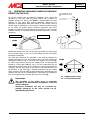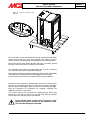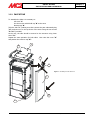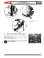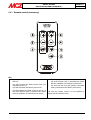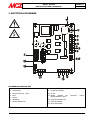
1
USE AND MAINTENANCE MANUAL MCZ GROUP S.p.A. - Via La Croce 8, I - 33074 Vigonovo di Fontanafredda (PN) Italy. 10 EN 14785 - 2006 Art. 15a B-VG / BImSchV / VKF AEAI Regensburger und Münchener BStV erfüllt. KAIKA / FACE Potencia nominal: Potência nominal: Nominal heat output: Brændværdi: Emisión CO ( al 13% de O2): Emissão CO (13% de O2): CO emission (at 13% O2) CO emission (ved 13% O2): Eficiencia: Eficiencia: Efficiency: Virkningsgrad: Temperadura humos: Tempretura dos fumos: Flue gas temperature: Røggastemperatur: Partículas dispersadas Partículas Dust Støv Asorbimiento electrico max: Potência electrica absorbida: Max. electrical power supply: Max. elektrisk effekt: Tensión de funcionamiento: Tensão electrica funcionamento: Rated voltage: Netspænding: Distancias de seguridad (retro): Distancia de segurança (trasiera): Safety clarence distance (back): Sikkerhedsafstand (bag): Distancias de seguridad (laterales): Distancia de segurança (lateral): Safety clarence distance (side): Sikkerhedsafstand (side): Max Min 6,0 kW 2,1 kW P max P min 0,013% 0,059% P max P min 92,8% 94,0% 160 °C 27 mg/Nm3 (13% O2) 14 mg/MJ 320 W (Med. 80 W) 230 V - 50 Hz. 50 mm 50 mm Producto conform e a la instalación de tubos m últiples. Produto conform e para instalação em condutas m ultiplas. Appliance suitable for installation in a shared flue. Apparatet kan bruges i en røggassam leledning. Utilizar sólo con com bustibles adaptados. Utilizar som ente com bustivel adaquado. Use only recom m ended fuels. Anvend kun anbefalede brændsler. Leer y seguir las instrucciones! Leia atentamente e siga as instruções! Leggere e seguire le istruzioni! Read and follow the operating instructions! Følg fabrikantens brugervejledning! COD: 8901007500 PELLET STOVES INSTALLATION AND USE MANUAL Contents page 3 INTRODUCTION .................................................................................................................................... 5 1. WARNINGS AND GUARANTEE CONDITIONS..................................................................................... 6 1.1. SAFETY INSTRUCTIONS ..................................................................................................................6 1.2. OPERATING WARNINGS ..................................................................................................................7 1.3. GUARANTEE CONDITIONS ..............................................................................................................8 1.3.1. Limitations ...............................................................................................................................8 1.3.2. Exclusions................................................................................................................................9 2. THEORETICAL NOTIONS FOR INSTALLATION ................................................................................ 10 2.1. 2.2. 2.3. 2.4. 2.5. 2.6. 2.7. 2.8. 2.9. PELLETS ...................................................................................................................................... 10 PRECAUTIONS FOR INSTALLATION ................................................................................................ 11 OPERATING AREA ......................................................................................................................... 12 CONNECTION TO THE EXTERNAL AIR INTAKE ................................................................................ 12 CONNECTION OF SMOKE DISCHARGE PIPE .................................................................................... 13 CONNECTION TO THE FLUE PIPE................................................................................................... 14 CONNECTION TO AN EXTERNAL FLUE WITH INSULATED OR DOUBLE-WALL PIPE ............................. 14 CONNECTION TO THE FLUE PIPE................................................................................................... 14 OPERATING PROBLEMS CAUSED BY DRAUGHT DEFECTS IN THE FLUE ............................................. 15 3. INSTALLATION AND ASSEMBLY ...................................................................................................... 16 3.1. DRAWINGS AND TECHNICAL CHARACTERISTICS ............................................................................ 16 3.1.1. FACE Air ................................................................................................................................ 16 3.1.2. KAIKA Air .............................................................................................................................. 16 3.1.3. Technical characteristics ......................................................................................................... 17 3.2. PREPARATION AND UNPACK ING ................................................................................................... 18 3.3. CLADDING ASSEMBLY ................................................................................................................... 21 3.3.1. KAIKA STOVE......................................................................................................................... 21 3.3.2. FACE STOVE .......................................................................................................................... 23 3.4. MAKING THE ELECTRICAL CONNECTIONS ...................................................................................... 24 4. OPERATION ..................................................................................................................................... 25 4.1. PRE-LIGHTING WARNINGS ............................................................................................................ 25 4.2. PRE-LIGHTING CHECK .................................................................................................................. 26 4.3. LOADING THE PELLETS ................................................................................................................. 26 4.4. CONTROL PANEL/REMOTE CONTROL DISPLAY (accessory) .............................................................. 27 4.4.1. Control panel logic.................................................................................................................. 27 4.5. SETTINGS TO CARRY OUT BEFORE FIRST LIGHTING ...................................................................... 29 4.6. FIRST LIGHTING .......................................................................................................................... 29 4.6.1. ON/OFF from the control panel or remote control (if purchased) ................................................ 29 4.6.2. Note on first ignition ............................................................................................................... 29 4.7. Power supply (panel display: ON) ................................................................................................... 30 4.8. OPERATING MODE........................................................................................................................ 30 4.8.1. Manual mode ......................................................................................................................... 30 4.8.2. Automatic mode ..................................................................................................................... 31 4.8.2.1. AUTOMATIC MODE SETTING ............................................................................................ 31 4.8.2.2. Changing from manual to automatic mode ......................................................................... 31 4.8.2.3. Cleaning the grate ........................................................................................................... 31 4.9. HOT AIR VENTILATION ................................................................................................................. 32 4.10. Room sensor ............................................................................................................................. 32 5. MENU STRUCTURE ........................................................................................................................... 33 The menu allows you to set/change a series of information: ................................................................... 33 MAIN MENU ........................................................................................................................................ 33 5.1. Setting current day and time.......................................................................................................... 33 Contents Technical service - Rights reserved MCZ GROUP S.p.A. - Reproduction prohibited PELLET STOVES INSTALLATION AND USE MANUAL Contents page 4 5.2. TIMER ......................................................................................................................................... 35 5.2.1. TIMER activation and selection of a programme........................................................................ 35 5.2.2. DETAILS OF TIMER OPERATION.............................................................................................. 36 5.2.3. TIMER de-activation. .............................................................................................................. 36 5.3. SLEEP FUNCTION ......................................................................................................................... 37 5.4. Menù IMPOSTAZIONI .................................................................................................................... 37 5.4.1. Setting the language .............................................................................................................. 37 5.4.2. Automatic mode with AUTO-ECO (panel display: ON-AUTO ECO) ............................................... 38 5.4.2.1. Mode AUTO-ECO ............................................................................................................. 39 5.4.3. Tones (Panel display: ON-OFF) ................................................................................................ 39 5.4.4. Pellet recipe - modifying the load ............................................................................................. 39 5.4.5. Changing the smoke exhaust fan speed – Var.% smoke rpm ..................................................... 40 5.4.6. Connection to a room thermostat ............................................................................................ 41 5.4.6.1. Operating mode with external thermostat .......................................................................... 42 5.4.6.2. Operating mode with external thermostat and Eco-Stop ...................................................... 43 5.4.7. Remote control (accessory) ..................................................................................................... 44 5.4.7.1. General characteristics of the LCD remote control ............................................................... 45 5.4.7.2. Type of batteries and replacement .................................................................................... 45 5.4.8. Hopper load (ON-OFF - only displayed with stove off) ............................................................... 45 5.4.9. Technical menu ...................................................................................................................... 46 5.5. INFO menu .................................................................................................................................. 46 6. SAFETY DEVICES ............................................................................................................................. 47 6.1. 6.2. 6.3. 6.4. ALARM SIGNALLING...................................................................................................................... 47 Exiting alarm condition .................................................................................................................. 48 Normal shutdown (panel display: shutdown) ................................................................................... 48 BLACKOUT WITH STOVE LIT (panel display: RELIGHTING AFTER BLACKOUT for 10’, then LIGHTING) 49 7. MAINTENANCE AND CLEANING ...................................................................................................... 50 7.1. DAILY AND WEEKLY CLEANING BY THE USER ................................................................................. 50 7.1.1. Before each lighting................................................................................................................ 50 7.1.2. Check every 2/3 days ............................................................................................................. 50 7.1.3. Cleaning the glass .................................................................................................................. 50 7.2. PERIODIC CLEANING BY A SPECIALISED TECHNICIAN .................................................................... 51 7.2.1. Cleaning of the heat exchanger ............................................................................................... 51 7.2.2. Shutting the stove down (end of season) ................................................................................. 52 7.2.3. Check of internal components ................................................................................................. 52 8. PROBLEMS / CAUSES / SOLUTIONS ...............................................................................................53 9. ELECTRICAL DIAGRAMS .................................................................................................................. 56 Contents Technical service - Rights reserved MCZ GROUP S.p.A. - Reproduction prohibited PELLET STOVES Chapter 1 INSTALLATION AND USE MANUAL page 5 INTRODUCTION Dear Customer, We wish to thank you for choosing an MCZ product, specifically a stove of the MCZ pellet line. In order to get the best performance from your stove and to enjoy to the full the warmth and the sense of well-being which the flame will diffuse through the home, we recommend that you read this booklet carefully before lighting the s tove for the first time. While thanking you again, may we remind you that the stove MUST NOT be used by children, and that they must always be kept at a safe distance from it! Revisions to the publication In order to improve the product, to keep this publication up to date the manufacturer reserves the right to make modifications without any advance notice. Any reproduction, even in part, of this manual without the consent of the manufacturer is prohibited. Care of the manual and how to consult it Take good care of this manual and keep it in a place which can easily and quickly be reached. If this manual should be lost or destroyed, or if it is in poor condition, ask for a copy from your retailer or directly from the manufacturer, providing product identification data. Information which is essential or that requires special attention is shown in bold text. Italic text is used to call your attention to other paragraphs in the manual or for any additional clarifications. SYMBOLS USED IN THE MANUAL ATTENTION This warning sign indicates that the message to which it refers should be carefully read and understood, because failure to comply with what these notices say can cause serious damage to the stove and put the user's safety at risk. INFORMATION This symbol is used to highlight information which is important for proper stove operation. Failure to comply with these provisions will compromise use of the stove and its operation will not be satisfactory. OPERATING SEQUENCES: Indicates a sequence of buttons to be pushed to access menus or to make adjustments. MANUAL Indicates that you should carefully read this manual or the related instructions. Introduction Technical service - Rights reserved MCZ S.p.A. - Reproduction prohibited PELLET STOVES INSTALLATION AND USE MANUAL Chapter 1 page 6 1. WARNINGS AND GUARANTEE CONDITIONS 1.1. SAFETY INSTRUCTIONS Installation of the stove, making the electrical connections, checking its operation, and maintenance are all tasks which should be carried out by qualified and authorised personnel. Install the stove according to all local and national laws and the European standards in force locally, regionally and in the country. This apparatus cannot be used by people (including children with limited physical, sensorial or mental abilities or with little experience and know-how unless they have been viewed or instructed on the use of the apparatus by the person responsible for its safety. For the correct use of the stove and of the electronic apparatus connected to it, and to prevent accidents, the instructions given in this booklet must always be followed. Use, adjustment and programming must be carried out by adults. Errors or incorrect settings may cause hazardous conditions and/or poor operation. Before beginning any operation, the user, or whoever is preparing to operate on the stove, must have read and understood the entire contents of this instruction booklet. The stove is to be used only for its intended purpose. Any other use is to be considered improper and therefore hazardous. Do not use the stove for standing on or as any kind of support. Do not put clothes to dry on the stove Any clothes hangers and suchlike must be kept a suitable distance from the stove. Danger of fire. All responsibility for improper use is taken entirely by the user and such use relieves MCZ of any civil or criminal responsibility. Any kind of tampering or unauthorised substitution of non-original spare parts can be hazardous for the safety of the operator and relieves MCZ of any civil or criminal responsibility. Most of the surfaces of the stove are extremely hot (the door, the handle, the glass, smoke discharge pipes etc.). Avoid coming into contact with these parts, therefore, without adequate protective clothing or suitable implements, such as gloves with thermal protection or implements which keep the hands cool. Under no circumstances should the stove be run with the door open or the glass broken. Do not touch the stove with wet hands, in view of the fact that it is an electrical appliance. Always disconnect the supply cable before doing anything to the unit. Warnings and guarantee conciliations Technical service - Rights reserved MCZ GROUP S.p.A. - Reproduction prohibited PELLET STOVES INSTALLATION AND USE MANUAL 1.2. Before carrying out any cleaning or maintenance operation, make sure in advance that the stove is disconnected from the mains electricity supply, by turning off the main switch located on the back of the stove, or by unplugging the supply cable. The stove must be electrically connected to a system equipped with an effective earth conductor. The system must be of adequate rated capacity for the stated electrical power of the stove. Incorrect installation or faulty maintenance (not conforming to the requirements set out in this booklet) can cause harm to people, animals or property. In such cases MCZ is absolved from any civil or criminal responsibility. Chapter 1 page 7 OPERATING WARNINGS Shut the stove down in the event of a breakdown or bad running. Pellets must not be fed manually into the burner. Accumulated unburnt pellets in the burner after repeated failed ignitions must be removed before lighting. Do not wash the inside of the stove with water. Do not wash the stove with water. The water could get inside the unit and damage the electrical insulation and cause electric shocks. Do not expose your own body to hot air for extended periods. Do not overheat the room you are in and where the stove is installed. This could cause injuries and health problems. Do not expose plants or animals directly to a current of hot air. There could be harmful effects on them Do not put any fuels in the hopper but wood pellets. Install the stove in a location with adequate means of fire-prevention and equipped with all services such as power supply (air and electricity) and fume discharge. If there is a fire in the flue pipe, extinguish the stove, disconnect it from the power supply and never open the door. Then contact the competent authorities. If the stove and the ceramic cladding are in storage, it should be in a place that is free of damp, and they should not be exposed to extremes of temperature. It is inadvisable to base the stove directly on the floor, and if the floor is made of flammable material, it must be suitably insulated. Do not light the stove with flammable materials if the ignition system breaks down. INFORMATION In case of any problems, get in touch with your dealer, or a qualified engineer authorised by MCZ, and if a repair is necessary, insist on the use of original spare parts. Warnings and guarantee conciliations Technical service - Rights reserved MCZ GROUP S.p.A. - Reproduction prohibited PELLET STOVES INSTALLATION AND USE MANUAL 1.3. Use only the fuel recommended by MCZ (for Italy pellets with a diameter of 6 mm and for other European countries with a diameter of 6-8 mm) and provided only with an automatic supply system. Periodically check and clean the smoke outlet ducts (connection to the flue pipe). The pellet stove is not a cooking appliance. Keep this instruction manual carefully because it must stay with the stove throughout its working life. If the stove is sold or transferred to another user, always make sure that the booklet goes with the product. If it gets lost, ask MCZ or your authorised dealer for another copy. Chapter 1 page 8 GUARANTEE CONDITIONS MCZ guarantees the stove, excluding the components which are subject to normal, for a period of two years from the date of purchase, as proved by a supporting document which gives the name of the vendor and the date on which the sale took place. The guarantee is conditional on the guarantee certificate being filled in and returned within 8 days, and requires that the product be installed and tested by a specialised installer, according to the detailed instructions given in the instruction booklet supplied with the product. The term 'guarantee' is to be understood to denote the freeof-charge replacement or repair of parts recognised to have been defective at the start by reason of manufacturing defects. 1.3.1. Limitations The above guarantee does not cover components relating to electrical and electronic parts, or fans, on which the guarantee period is 1 year from the purchase of the product, documented as specified above. The guarantee does not cover parts subject to normal wear such as gaskets, glass, and any parts with can be removed from the firebox. The replacement parts will be guaranteed for the remainder of the guarantee period starting from the date of purchase of the product. Warnings and guarantee conciliations Technical service - Rights reserved MCZ GROUP S.p.A. - Reproduction prohibited PELLET STOVES INSTALLATION AND USE MANUAL Chapter 1 page 9 1.3.2. Exclusions Variations in colour in the painted or ceramic parts, and crackling of the glaze on the ceramics, do not constitute grounds for a claim under the guarantee, as they are natural characteristics of the material and of the use of the product. The guarantee does not cover any parts which may be found to be faulty as a result of negligence or carelessness in use, or of incorrect maintenance, or of installation not complying with MCZ's specification (see the relevant chapters in this user manual). MCZ refuses to accept any responsibility for any damage which may be caused, directly or indirectly, by persons, animals or things in consequence of the failure to observe all the prescriptions laid down in the instruction booklet, especially those concerning warnings on the subject of installation, use and maintenance of the appliance. If the product does not perform correctly, contact your local retailer and/or importer. Damage caused by transport and/or handling is excluded from the guarantee. For installation and use of the product, reference must be made exclusively to the booklet supplied. The guarantee will be invalidated in the event of damage caused by tampering with the appliance, atmospheric agents, natural disasters, electrical discharges, fire, defects in the electrical system, and caused by lack of, or incorrect, maintenance in terms of the manufacturer's instructions. CLAIMS UNDER THE GUARANTEE the request for action under the guarantee must be addressed to the retailer, who will forward the claim to MCZ's technical assistance service. MCZ refuses to accept any responsibility in the event that the stove or any other accessory have been improperly used or modified without authorisation. For all replacement of parts, only original MCZ spare parts must be used. Warnings and guarantee conciliations Technical service - Rights reserved MCZ GROUP S.p.A. - Reproduction prohibited PELLET STOVES Chapter 2 INSTALLATION AND USE MANUAL page 10 2. THEORETICAL NOTIONS FOR INSTALLATION 2.1. PELLETS Wood pellets are manufactured by hot-extruding compressed sawdust which is produced during the working of natural dried wood. The compactness of the material comes from the lignin which is contained in the wood itself, and allows the production of pellets without the use of glues or binders. The market offers different types of pellet with characteristics which vary depending on what mixture of woods is used. The diameter varies between 6 mm and 8 mm, with a standard length in the range 5 mm to 30 mm. Good quality pellets have a density which varies between 600 kg/m3 and 750 kg/m3, with a moisture content which varies from 5% to 8% by weight. Fuel pellets Besides being an ecological fuel (exploiting timber residues to the maximum and achieving cleaner combustion than is possible with fossil fuels), pellets also have technical advantages. While good-quality timber has a calorific power of 4.4 kW/kg (with 15% moisture, therefore after about 18 months' seasoning), the equivalent figure for pellets is 4,9 kW/kg. To ensure good combustion, the pellets must be stored in an area that is free of humidity and protected from dirt. The pellets are usually supplied in 15 kg. sacks, so storing them is very convenient. Good quality pellets ensure good combustion, thus lowering the emission of harmful agents into the atmosphere. The poorer the quality of the fuel, the more frequently will intervention be necessary for cleaning the internal parts, such as the grate and the combustion chamber. 15 Kg sack of fuel The main certifications of quality for pellets in the European market are DINplus and Ö-Norm M7135; these ensure respect of: Calorific power: 4.9 kW/kg Water content: max 10% of weight Percentage of ashes: max 0,5% of weight Diameter: 5 – 6mm Length: max 30mm Contents: 100% untreated wood, with no added bonding substances (bark percentage 5% max) Packaging: in sacks made from ecologically compatible or biologically decomposing material Theoretical notion for installation Technical service - Rights reserved MCZ GROUP S.p.A. - Reproduction prohibited PELLET STOVES INSTALLATION AND USE MANUAL Chapter 2 page 11 MCZ strongly recommends using certified fuel in its stoves (DINplus e Ö-Norm M7135). The use of fuel of inferior quality or not conforming to the specification given above compromises the running of your stove and can therefore lead to the termination of the guarantee and of the manufacturer's responsibility for the product. MCZ pellet stoves run exclusively on pellets with a diameter of 6 mm (only for Italy) and 6-8 mm (European countries) with lengths that go from 5 mm to 30 mm. 2.2. PRECAUTIONS FOR INSTALLATION IMPORTANT! Installation and assembly of the stove must be carried out by qualified personnel. The stove must be installed in a suitable position to allow the normal operations of opening and ordinary maintenance. The site must be: capable of providing the environmental conditions for operation equipped with power supply 230V 50 Hz capable of taking an adequate system for smoke discharge provided with external ventilation provided with an earth connection complying with CE The stove must be connected to a flue pipe or an internal or external vertical duct conforming to current standards UNI 7129 - 7131 9615. The stove must be positioned in such a way that the electrical plug is accessible. IMPORTANT! The stove must be connected to a flue pipe or a vertical duct which can discharge the fumes at the highest point of the building. The fumes are however derived from the combustion of wood products, and if they come into contact with or close to walls, they can make dirty marks. Also take care because the fumes are very hot but almost invisible, and can cause burns on contact. The holes for the passage of the smoke pipe and for the intake of air from outside should be made before positioning the stove unit. Theoretical notion for installation Technical service - Rights reserved MCZ GROUP S.p.A. - Reproduction prohibited PELLET STOVES Chapter 2 INSTALLATION AND USE MANUAL 2.3. page 12 OPERATING AREA For proper functioning and a good temperature distribution, the stove should be positioned in a location where it is able to take in the air necessary for combustion of the pellets (about 40 m3/h must be available), as laid down in the standard governing the installation and in accordance with local national standards. The volume of the room must not be less than 30 m3. The air must come in through permanent openings made in walls (in proximity to the stove) which give onto the outside, with a minimum cross-section area of 100 cm2. These openings must be made in such a way that it is not possible for them to be obstructed in any way. Alternatively, the air can be taken from rooms adjacent to the one which needs ventilating, as long as they are provided with an air intake from the outside, and are not used as bedrooms or bathrooms, and provided there is no fire risk such as there is for example in garages, woodsheds, and storerooms, with particular reference to what is laid down in current standards. It is not permissible to install the stove in bedrooms, bathrooms, or in a room where another heating appliance is installed (fireplace, stove etc.) which does not have its own independent air intake. Example of pellet stove installation Locating the stove in a room with an explosive atmosphere is prohibited. The floor of the room where the stove is to be installed must be strong enough to take its weight. In the case of flammable walls, keep a minimum distance to the rear (A) of 5 cm, to the side (B) 5 cm, a minimum distance from the tube to the wall (E) of 5 cm and to the front 150 cm. If the room contains objects which are believed to be particularly delicate, such as drapes, sofas and other furniture, their distance from the stove should be considerably increased. If the flooring is made of wood, provide a floor protection surface in compliance with current national standards. 2.4. CONNECTION TO THE EXTERNAL AIR INTAKE Example of pellet stove installation It is essential that at least as much air must be able to flow into the room where the stove is installed as is required for proper combustion in the appliance and for the ventilation of the room. This can be effected by means of permanent openings in the walls of the room to be ventilated, which give onto the outside, or by single or collective ventilation ducts. For this purpose, on the external wall near the stove, a hole must be made with a minimum free cross-section of 100 cm². (equivalent to a round hole of 12 cm diameter or a square hole 10x10 cm), protected by a grille on the inside and the outside. The air intake must also: communicate directly with the room where the stove is installed Theoretical notion for installation Technical service - Rights reserved MCZ GROUP S.p.A. - Reproduction prohibited PELLET STOVES Chapter 2 INSTALLATION AND USE MANUAL page 13 be protected by a grille, metal mesh or suitable guard, as long as this does not reduce the area below the minimum. be positioned in such a way as to be impossible to obstruct It is not compulsory to connect the air intake directly with the stove (so that it draws air directly from outside), but it is essential at all events to ensure an airflow of 50 cubic metres per hour by the use of a hole of the dimensions given. See standard UNI 10683. 2.5. CONNECTION OF SMOKE DISCHARGE PIPE When making the hole for the passage of the smoke discharge pipe, it is necessary to take into account the possible presence of flammable materials. If the hole will be going through a wall made of wood or any other material which is sensitive to heat, the INSTALLER MUST first of all use the special wall union (diam.13cm 13cm minimum) and properly insulate the pipe of the stove that passes through it, using adequate insulation materials (thickness 1.35cm with minimum thermal conductivity of 0.07 W/m°K). The same is true if the stove pipe must run through vertical or horizontal stretches passing in proximity (min.20cm) to the heatsensitive wall As an alternative we recommend the use of insulated pipe, which can also be used on the outside to avoid condensation. The combustion chamber works in low pressure. The smoke duct for the discharge of fumes will also be under low pressure when connected to an efficient flue pipe as directed. 1 2 Rear view of a pellet stove 1) Combustion air intake 2) Smoke outlet Pipes and unions with suitable gaskets must always be used, to guarantee a hermetic seal. in mind all the instructions and IMPORTANT! All 90 degree changes of direction in the flue pipe must be fitted with suitable tee connectors to allow the possibility of inspection. (see accessories for pellet stove) It is absolutely prohibited to fit a grille on the end of the discharge pipe, because it could lead to poor running of the stove. FOR CONNECTION TO THE FLUE PIPE, NOT MORE THAN 2-3 METRES OF HORIZONTAL PIPE MUST BE USED AND NOT MORE THAN THREE 90° CURVES MUST BE USED IT IS ALSO ADVISABLE NOT TO EXCEED 6 METRES IN LENGTH WITH THE PIPE Ø 80 mm Theoretical notion for installation 3-5 % H > 1,5 mt. Position the stove bearing considerations above. H > 4 mt. All sections of the smoke duct must be inspectable and removable to enable periodic internal cleaning. Tee connectors with inspection caps should be used. 2 - 3 mt. MAX Example of pellet stove installation Technical service - Rights reserved MCZ GROUP S.p.A. - Reproduction prohibited PELLET STOVES Chapter 2 INSTALLATION AND USE MANUAL 2.6. CONNECTION TO THE FLUE PIPE The flue pipe must have internal dimensions not larger than 20 x 20 cm, or diameter 20 cm. In the event of larger dimensions, or of the flue pipe being in poor condition (for example cracks, poor insulation, etc.), it is advisable to fit a stainless steel pipe of suitable diameter inside the flue pipe throughout its length, right up to the top. Check with suitable instruments that there is a minimum draught of 10 Pa. At the bottom of the flue pipe, provide an inspection cap to allow periodic checking and cleaning, which must be done annually. Make a gas-tight connection to the flue pipe, using pipes and connectors as recommended by us. You must ensure that a windproof cowl should be fitted which complies with the standards in force. This type of connection ensures the evacuation of the fumes even in the event of a temporary power cut. page 14 1 0,5 mt. 2 3 1) Windproof cowl 2) Flue pipe 2.7. CONNECTION TO AN EXTERNAL FLUE WITH INSULATED OR DOUBLE-WALL PIPE The external fluepipe must have internal dimensions of minimum 10x10 cm or 10 cm diameter, and maximum 20x20 cm or 20 cm diameter. Check with suitable instruments that there is a minimum draught of 10 Pa. The only type of pipe which is permissible is insulated (double-walled) stainless steel, smooth on the inside, fixed to the wall. Flexible stainless steel pipe must not be used. At the bottom of the flue pipe, provide an inspection cap to allow periodic checking and cleaning, which must be done annually. Make a gas-tight connection to the flue pipe, using pipes and connectors as recommended by us. You must ensure that a windproof cowl should be fitted which complies with the standards in force. 3) Inspection 1 0,5 mt. 2 3 This type of connection ensures the evacuation of the fumes even in the event of a temporary power cut. 1) Windproof cowl 2) Flue pipe CONNECTION TO THE FLUE PIPE 3) Inspection For proper functioning, the connecting pipe between the stove and the chimney or flue duct must have a slope of not less than 3% in the horizontal stretches, the length of which must not exceed 2/3 metres, and the vertical distance between one tee connector and another (change of direction) must not be less than 1.5m. Check with suitable instruments that there is a minimum draught of 10 Pa. At the bottom of the flue pipe, provide an inspection cap to allow periodic checking and cleaning, which must be done annually. Make a gas-tight connection to the flue pipe, using pipes and connectors as recommended by us. You must ensure that a windproof cowl should be fitted which complies with the standards in force. This type of connection ensures the evacuation of the fumes even in the event of a temporary power cut. 0,5 mt. 2 - 3 mt. MAX 3-5 % H > 1,5 mt. 2.8. 1 2 3 1) Windproof cowl 2) Flue pipe Theoretical notion for installation Technical service - Rights reserved MCZ GROUP S.p.A. - Reproduction prohibited 3) Inspection PELLET STOVES Chapter 2 INSTALLATION AND USE MANUAL 2.9. OPERATING PROBLEMS CAUSED BY DRAUGHT DEFECTS IN THE FLUE Of all the weather and geographical conditions which affect the operation of a flue pipe (rain, fog, snow, altitude a.s.l., exposure to sunlight, direction of facing), the wind is unquestionably the most decisive. In fact, along with thermal depression caused by the difference in temperature inside and outside of the chimney, there is another type of depression or over-pressure: dynamic pressure caused by the wind. An updraft always increases depression and hence draught. A crosswind increases depression provided the cowl has been installed properly. A downdraft always decreases depression, at times inverting it. Least favourable points page 15 E.g. Downdraft at 45° of 8m/sec. Overpressure of 17 Pa E.g. Crosswind 2: 8 m/sec Depression of 30Pa Downdraft Most favourable position WIND High-pressure Low-pressure zone Besides the direction and force of the wind, the position of the flue and the cowl with respect to the roof of the building and the surrounding landscape is important. The wind also influences the operation of the chimney indirectly by creating high-pressure and low-pressure zones, not only outside the building but inside as well. In rooms directly exposed to the wind (2), an indoor high-pressure area can be created which can augment the draught in stoves and fireplaces, but it can be counteracted by the external high pressure if the cowl is situated on the side exposed to the wind (1). On the other hand, in the rooms on the opposite side from the direction of the wind (3), a dynamic depression can be created which competes with the natural thermal depression developed by the chimney, but this can be compensated for (sometimes) by locating the flue on the opposite side from the direction of the wind (4). WIND 1 4 2 3 1-2 = High-pressure zones 3-4 = Low-pressure zones IMPORTANT! The operation of the pellet stove is noticeably sensitive to the conformation and position of the flue which is adopted. Hazardous conditions can only be overcome by suitable setting-up of the stove carried out by qualified MCZ personnel. Theoretical notion for installation Technical service - Rights reserved MCZ GROUP S.p.A. - Reproduction prohibited PELLET STOVES Chapter 3 INSTALLATION AND USE MANUAL page 16 3. INSTALLATION AND ASSEMBLY 3.1. DRAWINGS AND TECHNICAL CHARACTERISTICS 7 185 191 376 486 58 506 Ø80 Ø42 205 315 920 3.1.1. FACE Air 7 185 166 351 466 58 452 Ø42 Ø80 205 314 896 3.1.2. KAIKA Air Installation and assembly Technical service - Rights reserved MCZ GROUP S.p.A. - Reproduction prohibited PELLET STOVES Chapter 3 INSTALLATION AND USE MANUAL page 17 3.1.3. Technical characteristics Technical characteristics Kaika – Face Overall thermal power Max. 6,0 kw / 5160 kcal/h Overall thermal power Min. 2.4 kw / 1720 kcal/h Yield at maximum 92,8 % Yield at minimum 94,0 % Temperature of exhaust smoke at maximum 160°C Temperature of exhaust smoke at minimum 100°C Dust 14 mg/Nm3 (13% O2) 7 mg/MJ CO at 13%O² at minimum and maximum 0.059 — 0.013% CO2 at minimum and maximum 4.1% – 8.0% Mass of smoke at minimum and maximum 4 – 6 g/sec Suggested draught at max power 0.10 mbar – 10 Pa Suggested draught at min power 0.05 mbar – 5 Pa Hopper capacity 20 litres Fuel pellet type Pellet diameter 6-8 mm. Length range 5-30 mm Pellet consumption per hour Operating time between re-fuelling 3 Min ~ 0.5 kg/h * At min~ 20 h * Max. ~ 1.45 kg/h * At max. ~ 7 h * Heatable volume m 129/40 – 147/35 – 172/30 ** Combustion air inlet External diameter 50 mm. Smoke outlet External diameter 80 mm. Maximum absorbed electrical power Max. 320 W – Med. 80 W Power supply frequency and voltage 230 Volts / 50 Hz Net weight 120 kg Weight with packaging 130 Kg * Data that may vary depending on the type of pellets used. **Heatable volume based on demand of cal/m3 40-35-30 (respectively 40-35-30 Kcal/h for m3) Appliance suitable for installation in a shared flue. Installation and assembly Technical service - Rights reserved MCZ GROUP S.p.A. - Reproduction prohibited PELLET STOVES INSTALLATION AND USE MANUAL 3.2. Chapter 3 page 18 PREPARATION AND UNPACK ING The KAIKA AND FACE stoves are delivered in one package formed of: o Structure packaging o Side and top packaging (Fig.1) for Kaika oven whereas the cast iron top of the Kaika stove is already positioned on the stove Open the packaging, remove the four screws that secure the base of the stove to the pallet, two to the right and two to the left (see figure 2-3), and position the stove in the selected place, ensuring that it is complies with the above instructions. Figure 1 – Stove packaging + steel sides Kaika stove Figure 2 - Removing packaging screws Face stove Installation and assembly Technical service - Rights reserved MCZ GROUP S.p.A. - Reproduction prohibited PELLET STOVES INSTALLATION AND USE MANUAL Chapter 3 page 19 Figure 3 - Removing packaging screws Kaika stove The stove body or unit must always be kept in a vertical position when moved, and moved only using carts. Special care must be used to protect the door and the glass from impacts that would damage them. Moving the product must always be done with care. If possible, unpack the stove in the area where it is going to be installed. The materials which make up the packaging are not toxic or harmful, so no special procedures for disposal by required. Their storage, disposal or possible recycling are therefore the responsibility of the final user, in compliance with current legislation on the subject. Do not store the stove unit or its cladding without their packaging. Position the stove without its cladding and connect it to the flue pipe. Use the four adjustable feet (J) to get the stove correctly levelled so that the smoke outlet (S) is lined up with the connecting pipe (H) . Once the operations for connection are complete, assemble the cladding (ceramics or steel sides). If the stove needs to be connected to a discharge pipe which goes through the rear wall (to connect up with the flue), take the greatest care to make sure that the joint is not stressed. If the smoke outlet of the stove is forced or used improperly to lift it or position it, the operation of the stove can be damaged irreparably. Installation and assembly Technical service - Rights reserved MCZ GROUP S.p.A. - Reproduction prohibited PELLET STOVES Chapter 3 INSTALLATION AND USE MANUAL page 20 H J S Installation and assembly J 1. Turn the feet clockwise to lower the stove 2. Turn the feet counterclockwise to lower the stove Technical service - Rights reserved MCZ GROUP S.p.A. - Reproduction prohibited PELLET STOVES Chapter 3 INSTALLATION AND USE MANUAL 3.3. page 21 CLADDING ASSEMBLY 3.3.1. KAIKA STOVE Position the steel top “A” and secure it using the four screws supplied “D” and “E” (two on the right and two on the left) from bottom upwards. Remove the back profile “C” already secured to the stove with three screws “F”, “G” and “H”. Take side “B” and insert it, corresponding to the holes, into plugs “M” and “N” prearranged on the front part of the stove. Secure side “B” using the uppers screws “L”. At this point remount profile “C” securing it with three screws “F”, “G” and “H” to the structure and to side “B” in steel. A F E C G L D B H Figure 4 – Assembling the sides Kaika stove Installation and assembly Technical service - Rights reserved MCZ GROUP S.p.A. - Reproduction prohibited PELLET STOVES Chapter 3 INSTALLATION AND USE MANUAL page 22 M D E N Figure 5 – Details of Kaika stove - side and top assembly Installation and assembly Technical service - Rights reserved MCZ GROUP S.p.A. - Reproduction prohibited PELLET STOVES INSTALLATION AND USE MANUAL Chapter 3 page 23 3.3.2. FACE STOVE To assemble the sides it is necessary to: Lift cover “A” Cut the two ties which hold top “B” to the stove Remove top “B”. Take the side “C” (making sure that it enters the part underneath plug “G”) and secure it to the top sheet of the stove using the two screws “E and F” provided. At the rear, the side should be secured to the structure using lower screw “D”. Repeat the same operation for both sides. Now raise the cover “A” and position the cast iron top “B”. B A E F Figure 6 – Assembling the sides Face stove C D G Installation and assembly Technical service - Rights reserved MCZ GROUP S.p.A. - Reproduction prohibited PELLET STOVES Chapter 3 INSTALLATION AND USE MANUAL page 24 G D Figure 7 – Details of the Face stove assembling the sides E F 3.4. MAKING THE ELECTRICAL CONNECTIONS Connect the supply cable first at the rear of the stove and then to an electrical outlet on the wall. The main switch located on the rear of the stove should be switched on only when you want to light the stove. If you do not intend to use the stove, it is advisable to keep it switched off. Electrical connection of the stove Installation and assembly Technical service - Rights reserved MCZ GROUP S.p.A. - Reproduction prohibited PELLET STOVES INSTALLATION AND USE MANUAL Chapter 4 page 25 4. OPERATION 4.1. PRE-LIGHTING WARNINGS Do not touch the stove during the first lighting, as it is during this phase that the paint sets. If you touch the paint, you may expose the steel surface. If necessary, touch up the paint with the aerosol spray in the original colour (see the section "Accessories for pellet stoves"). It is recommended to provide plenty of ventilation in the room during the initial lighting, as the stove will give off a small amount of smoke or odour due to the stabilisation of the paint. Do not stay near the stove, and as previously mentioned, ventilate the room. The smoke and the smell of paint will vanish after about one hour of operation. There are no health risks involved. The stove will be subject to expansion and contraction during the stages of lighting and cooling down, and may therefore make slight creaking noises. This phenomenon is absolutely normal, the structure being made of sheet steel, and must not be considered a fault. It is extremely important to be sure not to take the stove to full heat straight away, but to bring it gradually up to temperature. If in manual mode, use low heating powers (for example 1a-2a-3a ). During subsequent use, you will be able to make use of all available heating power (e.g. 4a-5a ). In this way you will avoid damage to the ceramic panels, the welds and the steel structure. Do not demand maximum heating performance immediately! As with automobiles, a running-in period is recommended, even if only for a short period of time (4/5 hours). Try to get familiar with the commands given from the control panel. Try to memorize the messages that the stove provides on the display. Operation Technical service - Rights reserved MCZ GROUP S.p.A. - Reproduction prohibited PELLET STOVES Chapter 4 INSTALLATION AND USE MANUAL 4.2. page 26 PRE-LIGHTING CHECK Check that all the safety conditions described above have been met. Make sure you have read and completely understood the contents of this instruction booklet. Remove any components which might burn from the firebox and from the glass (various instructions and adhesive labels). Check that the grate A is properly positioned and rests correctly on the base. A After long periods of disuse, remove from the hopper (using a vacuum cleaner with an extension) any remains of pellets which have lain there for some time, since they may have absorbed moisture, which changes their original characteristics and makes them unsuitable for burning. 4.3. LOADING THE PELLETS Fuel is loaded from the upper part of the stove by opening a door. Pour the pellets in the hopper; when empty, it will hold about 10 kg. This is easier if performed in two steps: Pour half of the contents into the hopper and wait for the fuel to settle on the bottom. Then pour in the rest Never remove the protection grille in the hopper. When filling, do not let the sack of pellets touch any hot surfaces. Do not place any type of fuel in the hopper other than pellets that are compliant with the specifications provided previously. Operation Technical service - Rights reserved MCZ GROUP S.p.A. - Reproduction prohibited PELLET STOVES INSTALLATION AND USE MANUAL Chapter 4 page 27 4.4. CONTROL PANEL/REMOTE CONTROL DISPLAY (accessory) 4.4.1. Control panel logic Reported below are some useful information to understand the navigation logic and use the control panel: The luminosity of the control panel is switched off after about 20” seconds of the keyboard being inactive. To switch on the back lighting again just press any of the buttons on the panel. The first screen that appears displays the operating status of the stove (ON, OFF, LIGHTING, SHUTDOWN..) that alternates with any other settings activated (TIMER, SLEEP, AUTO ECO..) By pressing any of the 4 keys around the display (C D E F) you access the stove's operation settings screen (level of the flame, fan, set temperature, manual or automatic mode..). From this level the 4 keys around the display assume “dedicated” functions, i.e. they directly refer to the corresponding words that appear in the 4 corners of the display (e.g.: the word in the top right hand corner refers to the D key). When a setting is modified in any menu level without confirming the modification using the “OK” key and leaving the keypad inactive for 60 seconds, the first screen automatically reappears and the modifications are not saved. If from any menu level the on/off (B) key is briefly pressed, the display automatically returns to the first screen (stove operating status) without saving any modifications not confirmed by he “OK” key. Operation Technical service - Rights reserved MCZ GROUP S.p.A. - Reproduction prohibited PELLET STOVES INSTALLATION AND USE MANUAL Chapter 4 page 28 KEY A. Display; indicates a series of information about the stove, as well as the identification code for any operating anomaly. B. ON/OFF key or ESC (exit the menu). C. Choice of air fan speed and menu scrolling. D. Access to the main menu and submenu E. Choice of operating mode MANUAL/AUTO F. Choice of flame power in manual mode and temperature in automatic mode. Menu scrolling. G. Receiver for the remote control N.B. on the control panel it will be possible to set the language Operation Technical service - Rights reserved MCZ GROUP S.p.A. - Reproduction prohibited PELLET STOVES Chapter 4 INSTALLATION AND USE MANUAL page 29 4.5. SETTINGS TO CARRY OUT BEFORE FIRST LIGHTING Once the power cord is connected to the rear part of the stove, place the switch, also on the rear, to position (I). The lighted button of the switch will come on. The switch located to the rear of the stove powers the system. The stove is off and on the panel the first screen appears with the word OFF; by pressing any key the screen with the word MENU will appear. 4.6. FIRST LIGHTING 4.6.1. ON/OFF from the control panel or remote control (if purchased) To switch the stove on and off, press the key B for 2 seconds on the control panel or the A button on the remote control (if purchased). During the start-up phase lasting about 15 minutes: B A Pellet loading is independent of the set power The room temperature temperature is reached fan only starts when B Once this phase ends the stove automatically enters in power supply mode. 4.6.2. Note on first ignition The first attempt at ignition may not be successful, since the feeder screw is empty and it is not always able to fill the grate with required amount of pellets in time to ensure normal ignition Also the subsequent lightings that follow after the pellets are depleted could fail, see par. 5.4.8. “Loading the hopper” CANCEL THE ALARM CONDITION FROM THE CONTROL PANEL (see paragraph 6.1). REMOVE PELLETS IN THE GRATE AND REPEAT LIGHTING Operation Technical service - Rights reserved MCZ GROUP S.p.A. - Reproduction prohibited PELLET STOVES Chapter 4 INSTALLATION AND USE MANUAL 4.7. page 30 Power supply (panel display: ON) Once the lighting phase has ended the stove goes to flame level 3 and then increases (or decreases, according to that required by the setting) power at one value per minute. There are three methods of setting the flame during operation at full power: Manual Automatic Eco stop Then grate cleaning is added, the stove runs this automatically according to the modes described below. 4.8. OPERATING MODE KAIKA-FACE stoves have two operating modes: MANUAL and AUTOMATIC. MANUAL mode allows adjusting the flame from power 1 to power 5, ignoring any ambient temperature measurements. This mode is indicated by the word MANU on the display of the control. AUTOMATIC mode, on the other hand, lets you set the desired temperature in the room of installation. The stove will control its power autonomously in order to reach and maintain the established temperature in the room. This mode is indicated by the word AUTO on the control panel. With this mode you can also use an advanced function called AUTOECO which is described later (paragraph 5.4.2.) At each lighting, the stove automatically sets to the operating mode that it was in the last time it shut down. 4.8.1. Manual mode Flame power is adjustable from a minimum of 1 to maximum of 5. The levels of power correspond to a different fuel consumption value: by setting 5 the room will be heated in less time, setting 1 the room temperature will be maintained for a longer period of time. The peculiarity of this setting is that the flame stays at the set value regardless of room temperature. 21.0°C 21.04 OFF Mode:MANU Fire:1 Menu Fan:2 Mode:MANU Fire:1 Menu Fan:2 The flame power setting is only effective after ignition and therefore in full working order. Manual mode Operation Technical service - Rights reserved MCZ GROUP S.p.A. - Reproduction prohibited PELLET STOVES Chapter 4 INSTALLATION AND USE MANUAL page 31 Con il pulsante in alto a sinistra selezionare la funzione MAN (modalità MANUALE). In questa modalità mediante il pulsante in basso a sinistra (F) è possibile regolare le 5 potenze caloriche della stufa, mentre con il tasto in basso a destra (C) la velocità dei ventilatori. 4.8.2. Automatic mode The AUTOMATIC working mode foresees that the desired room temperature is set on the control panel. 21.0°C 21.04 OFF The probe located on the back of the stove verifies room temperature and the flame is set at power P5 until such temperature is reached. When it is reached it automatically drops by one power per minute until it reaches P1 and stays there as long as such condition remains unchanged. When room temperature once again drops below that set, the flame automatically rises by one power per minute up to P5 and stays there until room temperature returns as desired once again, and so on. Mode:AUTO Temp:20° Menu Fan:2 Mode:AUTO Temp:20° Menu Fan:2 Automatic mode 4.8.2.1. AUTOMATIC MODE SETTING From the first screen with the word ON, press any key and the screen with the word MENU will appear. With the upper left button select the AUTO function (AUTOMATIC mode). In this mode using the bottom left button it is possible to adjust the temperature desired in the room. By pressing button Temp the temperature rises one degree at a time (until it reaches 35°C to then start again from 5°C). By holding the Temp key down you enter the menu for setting the temperature using arrow keys RH and LH 4.8.2.2. Changing from manual to automatic mode It is possible to pass from the MANUAL function to the AUTOMATIC function and vice-versa by selecting the related key on the control panel. 4.8.2.3. Mode:MANU Fire:1 Menu Fan:2 Cleaning the grate Totally independently the stove proceeds with internal over-ventilation in order to prevent obstructions in the grate holes. Nonetheless this does not exonerate users from the obligation of cleaning the grate daily. When cleaning the grate, the smoke extractor operates at maximum power for 30”. Operation Technical service - Rights reserved MCZ GROUP S.p.A. - Reproduction prohibited PELLET STOVES Chapter 4 INSTALLATION AND USE MANUAL 4.9. page 32 HOT AIR VENTILATION The KAIKA - FACE stove is equipped with an inner fan for the expulsion of the hot heating air that can be adjusted indifferently if the stove is in manual or automatic mode. 5 speeds can be selected as well as an automatic function. To select the speed, after pressing the bottom right button, press it again to increase or decrease the fan power. In addition to 5th speed there is an additional selection called AUTO function. This function lets you connect the fan speed to the flame power. With this option selected, the stove will independently select the fan speed based on the flame power. Such function allows ventilation speed to be "connected" to the flame power with a maximum of V3. When such operation is selected the stove shall independently select fan speed according to flame power up to a maximum of V3 (P1=V1; P2=V2; P3=V3; P4=V3; P5=V3) to avoid noise. In order to prevent the structure from overheating, avoid selecting low speeds when the stove is at maximum performance. 4.10. Room sensor The room probe (B) is located at the back of the stove; should this be near the fumes exhaust tube, we recommend to extract the room probe so that it sticks out by approximately 10 cm. In this way it will not be affected by the tube's heat and the measured temperature will be near to that of the room. It is advisable to do this operation during installation, since before extracting the probe (B) it is necessary to take off the clamp (C) that keeps it connected; operation possible by working inside the stove thus without the sides. To extract the probe (B) it is necessary to unscrew the protection cap (A) and slowly pull the probe (B). After extracting the probe (B) sufficiently, close the protection cap (A) again. ATTENTION! Once the clamp that binds the probe wire is taken off, avoid it coming into contact with the hot parts of the stove. Room temperature sensor Operation Technical service - Rights reserved MCZ GROUP S.p.A. - Reproduction prohibited PELLET STOVES INSTALLATION AND USE MANUAL Chapter 5 page 33 5. Menu Structure The menu allows you to set/change a series of information: MAIN MENU 5.1. DATE/TIME TIMER SLEEP (only with stove lit) SETTINGS Language Auto eco (ON-OFF) Tones (ON-OFF) Pellet recipe (set: +3 (15%) +2 (10%) +1(5%); 0; -1(-10%) -2(-20%) -3 (-30%) Var.% smoke rpm (set: +50 +40 +30 +20 +10; 0; -10, -20, -30) Thermostat (ON-OFF) Remote control (ON-OFF) Hopper load (ON-OFF - only displayed with stove off) Technical menu (accessible by a specialised MCZ technician - password required) o Stove type o Hours of Service o T Eco-off o Parameters o Components test o Counter memory INFO Stove type Software Total Hours No. lightings extractor RPM Smoke T. Exchanger voltage Hopper load Flame Setting current day and time By pressing the key concerning MENU the word SET will appear. Type SET and the programme will appear to change: hour minutes day day of month month year For example to change the time, when DAY appears on the display, press SET, the day will start to flash in the middle of the display, using Menu structure Technical service - Rights reserved MCZ GROUP S.p.A. - Reproduction prohibited PELLET STOVES Chapter 5 INSTALLATION AND USE MANUAL page 34 the keys on the lower left or right you change the day and then the hour, minutes, day number etc. with the same mode and according to necessity. All modifications made must be confirmed by pressing OK, otherwise they will not be saved. Key ESC takes you back to the previous screen. If for 60 seconds the keypad of the control panel is inactive, it returns to the start screen without saving the modifications. TIME ADJUSTMENT 21.0°C OFF 21.04 21.0°C OFF Mode:AUTO Temp:22°C Menu Fan:A Esc Set < Time and date > Esc < Menu structure 01 Day Ok > Esc < 21.04 01 Hours Ok > Esc < :57 Minutes Ok > Esc 09 < Day num. Esc < 06 Month Ok > Esc < Esc < 2010 Year Ok > Mode:AUTO Temp:22°C 2010 Year Ok > Ok > Menu Fan:A Technical service - Rights reserved MCZ GROUP S.p.A. - Reproduction prohibited PELLET STOVES Chapter 5 INSTALLATION AND USE MANUAL 5.2. page 35 TIMER This operating mode allows the programming of the start-up and shutdown of the stove in automatic mode. Normally, the deactivated. stoves have the PROGRAMMED mode 70°F 21.04 OFF The basic settings in PROGRAMMED mode are: Choice of lighting/shutdown times Choice of programme activation day Mode:AUTO Temp:72°F Menu Fan:A Setting the current date and time is essential for proper timer operation. See paragraph 5.1. to learn how to set the current date and time. Esc Set < Time and date > 5.2.1. TIMER activation and selection of a programme. There are six settable timer programmes, for each of these the user can decide lighting and shutdown times and the days of the week on which it is active. When one or more programmes are active, the panel alternatively displays the state of stove TIMER “n” where “n” is the number relating to the activated timer programmes, separated by a dash. Example: TIMER 1 (only timer 1 programme active) or TIMER 1-4 (timer 1 and 4 programming active) or TIMER 1-2-3-4-5-6 (all timer programmes active). EXAMPLE OF PROGRAMMING With the stove lit or off, enter MENU, scroll to the TIMER OFF option (or TIMER NUMBER OF THE ACTIVE TIMER/S). Prompts PROGRAMME 1 OFF, to activate it press the SET key, using the arrow key select ON and confirm with the OK key; the screen will now show Starting time programme and shall prompt 00.00 as a starting time, change the starting time using the right arrow key and press OK to confirm. The next screen prompts the shutdown time having a time 10 minutes later than that shown for lighting: press the right arrow key to change shutdown time and confirm with the OK key. Next the days of the week in which to activate, or not, the timer that has just been set: using the arrow key select ON or OFF and confirm with OK. If no days of the week is confirmed as active (ON), the timer programme in turn shall not be active in the status screen (see above). Esc Set < Chrono Off > Esc < On Set Program 1 > Esc < On Set Program 2 > Esc On Ok < program 2 > Esc 7:00 Ok < Start program 2 > Esc 7:00 Ok < Start program 2 > Menu structure Technical service - Rights reserved MCZ GROUP S.p.A. - Reproduction prohibited PELLET STOVES INSTALLATION AND USE MANUAL Chapter 5 page 36 5.2.2. DETAILS OF TIMER OPERATION 1. The lighting time scrolls from 00.00 (midnight) to 23.50 2. If you change the lighting time and set a value later than the shutdown time, the shutdown time automatically sifts to lighting time + 10 min. to avoid operative errors. 3. The shutdown time may be chosen between lighting time +10 min. and 00.00 (midnight). 4. If a timer programme switches the stove off at 00.00 (midnight) on one day and another programme lights it at 00.00 (midnight) of the next day: the stove remains continuously lit. 5. If the stove is lit and the timer active, it is possible to manually shutdown the stove by pressing the OFF key; the stove shuts down and shall relight automatically at the next time foreseen by the timer 6. Equally in the stove off and timer active state, press the ON key: the stove will light and shutdown at the time foreseen by the active timer. IMPORTANT NOTE The stove takes about 15 minutes to light. Take this into account when setting the start time. Likewise, stove shutdown requires about 30 minutes, during which the heat stored up by the stove is still released into the room. Keep this in mind for substantial fuel savings. 5.2.3. TIMER de-activation. To de-activate the timer, access the menu again by means of button OFF. ATTENTION! The TIMER function can be activated/deactivated whether the stove is on or off. If a timer programme has been activated, in the initial screen the stove operating status (on/off/start-up….) alternates with the word “TIMER P01 active” (example) Menu structure Technical service - Rights reserved MCZ GROUP S.p.A. - Reproduction prohibited PELLET STOVES Chapter 5 INSTALLATION AND USE MANUAL 5.3. page 37 SLEEP FUNCTION This function is only displayed with the stove lit and its purpose is to make selecting a programmed shutdown faster, without the need to programme the stove's internal TIMER. To explain the SLEEP function in simple terms, basically it allows the stove to be turned off starting from a minimum of + 10 minutes respect the time read (example, if it is now 8:50, the first shutdown shall be 10 minutes later, that is at 9:00) and a maximum of 23.50 hours. To set the function press Menu with the top right key then in the screen the word Date and Time appears, therefore scroll with the bottom right key until the word Sleep appears, confirm with Set. With the bottom right key set the shutdown time. To confirm the choice press OK (top right) otherwise quit without saving any setting with ESC (top left) If the SLEEP function is active with TIMER active, the former has priority, so that the stove shall not shutdown at the time foreseen by the timer but at the time established by the sleep function. 21°C 21.04 OFF Mode:AUTO Temp:22°C Menu Fan:A Esc Set < Time and date > Esc < Off Chrono Set > Esc < Off Sleep Ok > Once the sleep function is set, in the first screen the status of the stove (on/off) alternates with the sleep wording HH.MM. (HOURS-MINUTES). When adjusting the sleep function, holding the right arrow key down when you reach 23.50 of the current day the panel prompts a stop: release it and press again to go on to the next day. 5.4. Esc < 02:00 Sleep Ok > Menù IMPOSTAZIONI 5.4.1. Setting the language From the start screen, press any key and the screen with the word MENU will appear. Press the key relative to MENU then scroll using the lower right or lefts keys (“F” and “C”) until the word SETTINGS appears, press SET the word LANGUAGE appears, press SET again to set the prechosen language. The following abbreviations are used for the days of the week deriving from the language set in the panel: In the case of English: MO Monday TU Tuesday WE Wednesday TH Thursday FR Friday SA Saturday SU Menu structure Sunday Technical service - Rights reserved MCZ GROUP S.p.A. - Reproduction prohibited PELLET STOVES Chapter 5 INSTALLATION AND USE MANUAL 21.0°C OFF 21.04 Mode:Auto Temp:22°C page Menu Fan:A Esc Set < Time and date > Esc < Esc < Settings Esc It Set < Language > Set > Esc It Ok < Language > 5.4.2. Automatic mode display: ON-AUTO ECO) Settings 38 Set > Esc It Ok < Language > with AUTO-ECO (panel Activation of this mode is performed through the MENU - SETTINGS AUTO ECO-ON. As for AUTO mode, the desired room temperature is set; when the set temperature < room temperature condition is reached (room temperature achieved) the "ECO shutdown T" begins to decrease (default 10 minutes, changeable within the technical menu by an authorised MCZ technician). During this phase on the small panel display remains ON-ECO ACTIVE, but the flame drops automatically by one power per minute until it reaches P1 and stays there until the programmed "ECO shutdown T" lapses and if the room temperature is still achieved, it moves on to the shutdown phase. ECO stop shutdown follows the normal shutdown procedure, whilst on the penal the wordings "SHUTDOWN" and "ECO ACTIVE" alternate. The possibility of adjusting "ECO shutdown T" derives from the necessity of correct operation in the various environments in which a stove may be installed and avoiding continuous shutdowns and lightings in the case in which the room temperature is subject to constant changes (air currents, low room insulation etc.) Once the stove shutdown conditions are reached, on the panel the words "OFF" and “ECO ACTIVE” alternate. Menu structure Technical service - Rights reserved MCZ GROUP S.p.A. - Reproduction prohibited PELLET STOVES Chapter 5 INSTALLATION AND USE MANUAL 21.0°C OFF 5.4.2.1. 21.04 Mode:Auto Temp:22°C page Menu Fan:A Esc Set < Time and date > Esc < Esc It Set < Language > Esc Off < Auto Eco Set > Esc Off < Auto Eco Ok > Esc On < Auto Eco Ok > Esc On < Auto Eco Ok > Settings 39 Set > Mode AUTO-ECO When ECO-STOP is activated and the chosen temperature selected, if the latter is lower than the current room temperature, the apparatus will immediately start counting the “ECO shutdown T”. In the event of chosen temperature higher than room temperature the apparatus shall continue to work at full power until the requested temperature is reached. 5.4.3. Tones (Panel display: ON-OFF) This setting deactivates sound when pressing the keys. It does not effect alarm signalling. 5.4.4. Pellet recipe - modifying the load This function is for adapting the stove to the pellets in use. In fact, as they are several types of pellet on the market, stove operation is strongly variable according to higher or lower fuel quality. In the event that pellets tend to get blocked in the grate due to excessive load of fuel or in the case in which the flame is always high even at low powers and vice versa if the flame is low, it is possible to decrease/increase the pellet feed rate into the grate: Menu structure Technical service - Rights reserved MCZ GROUP S.p.A. - Reproduction prohibited PELLET STOVES INSTALLATION AND USE MANUAL Chapter 5 page 40 1. Press the button on the top right “D” of the display to access the menu 2. Using the two lower keys “F” and “C” scroll through the various menus until you reach the SETTINGS menu. 3. Press button "D" corresponding to the word SET. 4. Using the two lower keys “F” and “C” scroll through the various menus until you reach the PELLET RECIPE menu. 5. Confirm by pressing the button "D" in correspondence to SET. 6. Change the value using lower keys “F” and“C” corresponding to symbols + and – 7. Confirm by pressing the button "D" in correspondence to key OK. The available values are: - 3 = 30% decrease in pellets at all powers. - 2 = 20% decrease in pellets at all powers. - 1 = 10% decrease in pellets at all powers. 0 = no variation 1 = 5% increase in pellets at all powers. 2 = 10% increase in pellets at all powers. 3 = 15% increase in pellets at all powers. 5.4.5. Changing the smoke exhaust fan speed – Var.% smoke rpm In the installation proves difficult for smoke discharge (lack of draught or even pressure in the conduit), it is possible to increase the smoke and ash exhaust speed. Such modification is also the best way to solve all potential problems of pellet blockages in the grate and sediments on the bottom of the grate which are created by bad quality fuel or which release a lot of ash. 1. Press the button on the top right “D” of the display to access the menu 2. Using the two lower keys “F” and “C” scroll through the various menus until you reach the SETTINGS menu. 3. Press button "D" corresponding to the word SET. 4. Using the two lower keys “F and "C" scroll through the various menus until you reach VAR. SMOKE RPM. 5. Confirm by pressing the button "D" in correspondence to SET. 6. Change the value using lower keys “F” and“C” corresponding to symbols + and – 7. Confirm by pressing the button "D" in correspondence to key OK. The available values range from -30% to +50% with variations of 10 percentage points at the time. Menu structure Technical service - Rights reserved MCZ GROUP S.p.A. - Reproduction prohibited PELLET STOVES Chapter 5 INSTALLATION AND USE MANUAL page 41 5.4.6. Connection to a room thermostat The room thermostat is not included with the stove and it must be installed by a specialised technician. WARNING! The electrical wires must not be in contact with the hot parts of the stove. The stove can also be connected to a room thermostat. The procedure to follow for the connection of the external thermostat is the following: Connect the two wires of the cable which come from the room temperature to the two free terminals of the connector (position 14 wiring diagram chap.7). To do this it is necessary to: o unscrew the protective cap of the probe o Pass the two wires through the protective cap and insert them into the hole together with the probe. o Pull the two wires to carry out connection to the board corresponding to terminal 14 (see chap.7) o Close the protective cap again. SONDA PROBE POS.14 THERMOSTAT CABLE CAVO TERMOSTATO AMBIENTE Menu structure Technical service - Rights reserved MCZ GROUP S.p.A. - Reproduction prohibited PELLET STOVES Chapter 5 INSTALLATION AND USE MANUAL 5.4.6.1. page 42 Operating mode with external thermostat In the SETTINGS - THERMOSTAT MENU select ON and exit the menu; at this point, by selecting the AUTO operating mode (para 2.2) in the place of the room temperature the word OFF will appear as the external thermostat takes control of the stove. (contact open = temperature achieved = stove on minimum; contact close = temperature not achieved = stove on maximum) In the condition of temperature achieved (thermostat contact open) the stove does not shutdown but automatically modulates the flame to minimum power; when the temperature is not achieved (thermostat contact closed) the stove automatically modulates the flame to maximum power. 21.0°C OFF Mode:Auto Temp:22°C Esc < Settings Set > Esc < Esc < It Set Language > Esc Esc Esc Menu structure 21.04 OFF Ok Thermostat Esc Settings Menu Fan:A Set > OFF Set Thermostat On Ok Thermostat On Ok Thermostat Technical service - Rights reserved MCZ GROUP S.p.A. - Reproduction prohibited PELLET STOVES INSTALLATION AND USE MANUAL Chapter 5 page 43 5.4.6.2. Operating mode with external thermostat and Eco-Stop When the external thermostat and Eco Stop are active the stove actuates the operating conditions described in para. 5.4.6.1, replacing the command coming from the thermostat at the temperature read by the probe, so that: - When the temperature is achieved (thermostat contact open) the decrease in ECO shutdown T" starts (default 10 minutes, changeable (*) from inside the TECHNICAL MENU). During this phase on the small panel display remains ON-ECO ACTIVE, but the flame drops automatically be one power per minute until it reaches P1 and stays there until the programmed "ECO shutdown T" lapses and if the thermostat is still open, it moves on to the shutdown phase. Once the stove shutdown conditions are reached, on the panel the words "OFF" and “ECO ACTIVE” alternate In this state if the room temperature drops below that set (thermostat contract closed) the stove relights without any delay. Menu structure Technical service - Rights reserved MCZ GROUP S.p.A. - Reproduction prohibited PELLET STOVES INSTALLATION AND USE MANUAL Chapter 5 page 44 5.4.7. Remote control (accessory) KEY 1. ON key 2. OFF key 3. Key that increases the flame's power level. The maximum power is 5. 4. Key that decreases the flame's power level. 5. Key that adjusts the speed of the hot air fan. If the AUTO function (key 7) activates, this means that the ventilation is connected to the power. Menu structure 6. Key that adjusts the speed of the hot air fan. If the AUTO function (key 7) activates this means that the ventilation is connected to the power. 7. Key that sets the room fan speed in automatic mode (connected to the flame's power level) N.B. from the remote control it is not possible to activate the ECO-STOP function Technical service - Rights reserved MCZ GROUP S.p.A. - Reproduction prohibited PELLET STOVES INSTALLATION AND USE MANUAL Chapter 5 page 45 5.4.7.1. General characteristics of the LCD remote control The KAIKA and FACE stoves are mainly controlled by the control panel that is found above the stove. As an accessory, it is in any case possible to purchase the remote control that manages the main functions: on/off, power adjustment, hot air fan speed adjustment, automatic function. The remote control is activated on the stove control panel on settings remote control – ON-OFF. The remote control is the infrared type so the signal cannot pass beyond walls or other solid obstacles, it can however exploit the reflection of the waves on the walls of the room. Keep the remote control away from direct heat and water. It is advisable to keep it out of the reach of children. 5.4.7.2. Type of batteries and replacement To substitute the battery, it is necessary to extract the battery-holder (as shown on the figure on the back of the remote control), and remove or insert the batteries following the symbols printed on the remote control and the battery itself. Operation requires 1 CR 2025 Lithium battery. Used batteries contain metals which are harmful for the environment; they must therefore be disposed of separately in the special containers. If the remote control is off due to the absence of batteries, it is possible to control the stove from the control panel, located in the upper part of the stove. The batteries provided have a limited lifespan to allow first lighting of the stove and for the user to learn how to use the device. When replacing the batteries, ensure correct polarity by observing the symbols on the internal compartment of the remote control. 5.4.8. Hopper load (ON-OFF - only displayed with stove off) This parameter, only displayed when the stove is off, allows the pellet to be loaded in the loading system (hopper) and can be used every time it is emptied when the pellets in the tank run out (see alarm A02). It is useful for preventing the stove from not lighting (alarm A01) because the tank has been emptied. When the pellet starts its descent into the grate press the Esc key and proceed with lighting the stove Menu structure Technical service - Rights reserved MCZ GROUP S.p.A. - Reproduction prohibited PELLET STOVES Chapter 5 INSTALLATION AND USE MANUAL 21.0°C OFF 21.04 Mode:Man Fire:5 page Menu Fan:5 Esc Set < Time and date > Esc < Esc It Set < Language > Esc Set < Screw loading > Esc Esc Enabled Screw loading Ok Screw loading 46 Settings Set > 5.4.9. Technical menu A password used by an authorised MCZ technician is required to access this menu. 5.5. INFO menu The "INFO” menu supplies indications concerning the instantaneous operating state of the stove, see para.4.6. Menu structure Technical service - Rights reserved MCZ GROUP S.p.A. - Reproduction prohibited PELLET STOVES Chapter 6 INSTALLATION AND USE MANUAL page 47 6. SAFETY DEVICES The stove is fitted with the following safety devices: SMOKE TEMPERATURE SENSOR. Monitors the temperature of the smoke, and gives permission for start-up or shuts the stove down when the smoke temperature falls below the preset value. PELLET HOPPER TEMPERATURE SENSOR. If the temperature surpassed the set safety value, it immediately halts the stove's operation and to restart it is necessary to wait until the stove has cooled down ELECTRICAL SAFETY The stove is protected against violent surges of current by the main fuse, which is located on the control panel at the rear of the stove. Other fuses to protect the electronic boards are to be found on the boards themselves. FAILURE OF THE SMOKE EXTRACTION FAN If the fan stops, the electronic board rapidly shuts off the supply of pellets and an alarm is displayed. BREAKDOWN OF THE REDUCTION MOTOR If the gear motor stops, the stove shuts down and the relative alarm is signalled TEMPORARY POWER CUT If there is a power outage during operation, when the power comes back on the stove will go into cooling mode and then it will come back on automatically. FAILURE TO LIGHT If during ignition no flame develops, the stove will go into alarm condition. TAMPERING WITH PROHIBITED THE SAFETY DEVICES IS It is only after eliminating the cause which gave rise to the intervention of the safety system, that it is possible to relight the stove and thus reset the automatic operation of the sensor. To understand which anomaly has occurred, consult this manual at paragraph 6.1 which explains what to do based on the alarm message the stove displays. 6.1. ALARM SIGNALLING Should an operating condition other than that foreseen for normal stove operation take place an alarm condition is triggered. The control panel shows the reason for the alarm in progress and by pressing the info key summarised instructions are given on how to proceed to restore the stove. The alarm sound signalling is not foreseen for A01 and A02 so that the user is not disturbed if pellets run out during the night. Safety devices Technical service - Rights reserved MCZ GROUP S.p.A. - Reproduction prohibited PELLET STOVES Chapter 6 INSTALLATION AND USE MANUAL page 48 The table below describes the possible alarms signalled by the stove, associated to the respective code that appears on the emergency panel, and useful suggestions to solve the problem. MESSAGE ON DISPLAY SOLUTION Check the level of pellets in the hopper. A01 Fire fails to ignite A02 Fire extinguishes abnormally A03 6.2. TYPE OF PROBLEM Check that the grate is properly inserted in its housing and does not have any obvious unburnt incrustations; Check the level of pellets in the hopper. Check that the grate is properly inserted in its housing and does not have any obvious unburnt incrustations; Pellet tank temperature exceeds foreseen Wait for the end of the cooling phase, cancel the alarm and relight the stove placing the fuel load to minimum safety limit. (SETTINGS MENU - Pellet recipe) and increasing the room Structure has overheated due to reduced heat fan speed. (V1-V5). If the alarm persists, contact technical dissipation support. Check that the grate does not have visible unburnt incrustations. If the alarm persists, contact technical support. A08 Anomalous operation of smoke fan. A09 Smoke temperature too high or smoke probe and relight the stove placing the fuel load to minimum (section 5.4.4.) and increasing the room fan speed (section faulty Wait for the end of the cooling phase, cancel the alarm 5.4.5). If the alarm persists, contact technical support. Exiting alarm condition To reset the alarm hold the On/Off key down for a few moments: the stove runs a check to assess whether the cause of the alarm persists or not. In the first case the alarm will be displayed once again, in the second case it will go to Off. Only after the cause of the blockage has been permanently eliminated can another attempt to relight the stove be made. 6.3. Normal shutdown (panel display: shutdown) If the shutdown key is pressed or there is an alarm signal, the stove enters the thermal shutdown phase foreseeing automatic execution of the following phases: Pellet loading stops The room fan maintains set speed until smoke T reaches 100°C, then it automatically sets to minimum speed until shutdown temperature is reached The smoke fan sets on maximum and stays there for a fixed time of 10 minutes, at the end of which if smoke T has dropped below 45°C (parameters can be displayed in the INFO menu) it shuts down definitively, otherwise it sets to minimum speed until such threshold is reached and then shuts down. Safety devices Technical service - Rights reserved MCZ GROUP S.p.A. - Reproduction prohibited PELLET STOVES INSTALLATION AND USE MANUAL Chapter 6 page 49 6.4. BLACKOUT WITH STOVE LIT (panel display: RELIGHTING AFTER BLACKOUT for 10’, then LIGHTING) In the case of no mains supply (BLACKOUT) the stove performs as follows: Blackout less than 10”: it restores operation in progress; If there is no power supply for more than 10" when the stove is lit or in the lighting phase, when the stove is powered again it returns to the previous operating condition following the procedure below: 1. It cools down by activating the smoke extractor at the minimum for 10’ and proceeds to the next point; 2. It restores the stove to the operating condition before the blackout. During phase 1 the panel displays RELIGHTING AFTER BLACKOUT. During phase 2 the panel displays Lighting. If during phases 1-2 the stove receives commands from the panel (or from the remote control) and therefore manually performed by the user, the stove stops running blackout recovery and proceeds with lighting or shutdown as the command requests. If the power supply cut is LONGER THAN 10” with the stove in shutdown phase, when the stove is powered again it restarts in shutdown mode even if the smoke temperature has dropped below 45°C in the mean time. This last phase can be skipped by pressing key 0/1 (passes on to lighting) and by pressing it again (it recognises that the stove is off). Clean the grate “F” from ash and any incrustations which could obstruct the air passage holes. Safety devices Technical service - Rights reserved MCZ GROUP S.p.A. - Reproduction prohibited PELLET STOVES Chapter 7 INSTALLATION AND USE MANUAL page 50 7. MAINTENANCE AND CLEANING ATTENTION! All cleaning of all parts must be carried out with the stove completely cold and unplugged. The stove does not need much maintenance if used with certified quality pellets. 7.1. DAILY AND WEEKLY CLEANING BY THE USER Example of clean grate 7.1.1. Before each lighting Clean the grate “F” of ash and any incrustation which could obstruct the passage of air. In the case of pellet depletion, unburnt pellet in the grate could accumulate in the hopper. Always empty the residuals from the grate prior to each lighting. Example of dirty grate REMEMBER THAT ONLY A CORRECTLY POSITIONED AND CLEAN GRATE CAN GUARANTEE THE OPTIMAL LIGHTING AND OPERATION OF YOUR PELLET STOVE. For good cleaning of the grate, pull it completely out of its housing and thoroughly clean the grate and holes on the bottom. If you use goodquality pellets, you will normally only need to use a paintbrush to restore the perfect condition of the component. 7.1.2. Check every 2/3 days G Clean and empty the ash drawer, watching out for hot ash. F Only if the ash is completely cold, it is possible to use a vacuum cleaner to remove it. Use a drum-type vacuum cleaner that is suitable for picking up particles of a certain size. Experience, and the quality of the pellets used, will determine the frequency of cleaning. It is however advisable not to let it exceed 2 or 3 days. Once the operation is finished, reinsert the ash drawer below the grate making sure it is well inserted Cleaning the ash collection compartment 7.1.3. Cleaning the glass For cleaning the ceramic glass, the use of a dry brush is recommended, or if it is very dirty, the special spray detergent, applying a small quantity then cleaning with a cloth. ATTENTION! Do not use abrasive products and do not spray the cleaning product on the glass of the painted parts or on the gaskets of the fire door (ceramic fibre cord) Maintenance and cleaning Cleaning the glass Technical service - Rights reserved MCZ GROUP S.p.A. - Reproduction prohibited PELLET STOVES Chapter 7 INSTALLATION AND USE MANUAL 7.2. PERIODIC CLEANING TECHNICIAN BY A page 51 SPECIALISED 7.2.1. Cleaning of the heat exchanger After the winter you will need to clean the compartment where discharge smoke passes. This cleaning must be done in order to remove all combustion residues before time and humidity let them harden and make them difficult to remove. CLEANING THE EXCHANGER: CLEANING THE UPPER COMPARTMENT - KAIKA STOVE When the stove is cool lift cover “D” and remove in sequence: profile “C”, sides “B” and top “A” as explained in section.3.3.1. Remove cover “E” which is secured to the structure by four screws (two at the front and two at the rear), then slide out the insulation B panel “F” and remove the panel “G” unscrewing the two screws on the right and the two screws on the left. The underlying surface features a small plate “H” secured by two screws, remove this piece too and access the inspection hole for cleaning (see arrow). Using a stiff rod or a bottle brush, scrape the inner walls of the fire box so that the ashes drop into the lower ash compartment. Clean and refit N all the components. CLEANING THE UPPER COMPARTMENT FACE STOVE When the stove is cool lift cover “A” and remove in sequence: top “B” and sides “C” as explained in section. 3.3.2. Remove cover “D” which is secured to the structure by four screws (two at the front and two at the rear), then slide out the insulation panel “E” and remove the panel “F” unscrewing the two screws on the right and the two screws on the left. The underlying surface features a small plate “H” secured by two screws, remove this piece too and access the inspection hole for cleaning (see arrow). Using a stiff rod or a bottle brush, scrape the inner walls of the fire box so that the ashes drop into the lower ash compartment. Clean and refit all the components. A F E G D H C B M L Cleaning the exchanger KAIKA stove B D E A F G CLEANING THE UPPER COMPARTMENT KAIKA-FACE STOVE Clean as explained in section 6 around the grate"N". Slide out drawer C “M”, then remove plate “L” unscrewing the two screws and using the vacuum cleaner nozzle, remove the ash and soot accumulated in the N lower heat exchanger indicated by the arrow. C CLEANING OF SMOKE DUCT AND GENERAL CHECKS: Clean the smoke discharge system, especially in the area of the tee connectors, curves and any horizontal stretches of pipe. For information on cleaning the flue pipe, contact a professional chimney sweep. Check the seal of the ceramic fibre gaskets on the door of the stove. If necessary, order new gaskets from the retailer for replacement or contact an authorized service centre to carry out this work. Maintenance and cleaning M L Cleaning the exchanger FACE stove Technical service - Rights reserved MCZ GROUP S.p.A. - Reproduction prohibited PELLET STOVES Chapter 7 INSTALLATION AND USE MANUAL page 52 ATTENTION: The frequency with which the smoke discharge system is cleaned should be determined based on the type of use that is made of the stove and the type of installation. MCZ suggests relying on an authorized service centre for end-of-season cleaning and maintenance, who will carry out all of the previously mentioned work and make a general check of the stove's components. 7.2.2. Shutting the stove down (end of season) At the end of season, before shutting down the stove, we recommend completely removing pellets from the hopper with the use of a vacuum cleaner with an extension. During periods of disuse, the stove must be unplugged and placed in a dry place protected from the elements. For greater safety, especially if there are children around, we recommend removing the supply cable from the rear of the stove. Upon re-start, when pressing the main switch (located on the back of the stove) does not make the control panel display light up, it could mean that the service fuse needs replacing. On the rear of the stove there is a fuse holding compartment which is located underneath the supply socket. Use a screwdriver to open the fuse-holder compartment and if necessary replace them (3.15 AT delayed) 7.2.3. Check of internal components ATTENTION! The check of the internal electro-mechanical components must be carried out only by qualified personnel with technical knowledge of electricity and combustion. We recommend that an annual maintenance service is carried out, preferably under a programmed service contract. The essential part of this service is a visual and functional check on the internal components: The following is a summary of the checks and/or maintenance tasks which are indispensable for the correct operation of the stove. PARTS / INTERVAL Grate Ash collection t t Ash drawer Glass 1 DAY ● 2-3 DAYS 30 DAYS ● ● ● ● Lower heat exchanger Complete exchanger Smoke duct Door seal Air filter Remote control battery (if purchased/optional) Maintenance and cleaning 60-90 DAYS ● ● 1 YEAR ● ● ● ● Technical service - Rights reserved MCZ GROUP S.p.A. - Reproduction prohibited PELLET STOVES Chapter 8 INSTALLATION AND USE MANUAL page 53 8. PROBLEMS / CAUSES / SOLUTIONS ATTENTION: All repairs must be carried out exclusively by a specialised technician, with the stove completely cold and the electric plug pulled out. PROBLEM Pellets not being fed into the combustion chamber. POSSIBLE CAUSES REMEDY Refill pellet hopper. Empty the hopper and manually free the feeder screw of sawdust. Replace reduction motor. Replace electronic board. Refill pellet hopper. See previous problem.. Let the stove cool down completely, reset the thermostat till lockout ceases, relight stove; if problem persists, contact technical assistance. Check if the timer setting is active Close the door or replace the gaskets with original spare parts. Change to a type of pellet recommended by the manufacturer. Have the fuel feed rate checked by technical service. Clean the combustion chamber, following instructions in the manual. Clean the smoke duct. Check the motor and replace if necessary. Re-run lighting cycle. Wait for automatic restart Clean smoke duct. Check and replace sensors as necessary. Pellet hopper empty. Feeder screw blocked by sawdust. Reduction motor defective. Defective electronic board. Pellet hopper empty. Pellets not being fed in. Intervention of pellet temperature sensor. Timer active Door not closed properly or gaskets worn. Unsuitable pellets. Low pellet feed rate. Combustion chamber dirty. Smoke outlet obstructed. Smoke extraction motor failed. The stove runs for a few minutes and then goes out. Lighting cycle not completed. Temporary failure of electricity supply. Smoke duct obstructed. Temperature sensors defective or broken. Pellets build up in grate, door glass gets dirty and flame is weak. Insufficient combustion air. Check that the room air intake is present and free. Clean the grate and check that all the airways are clear. Carry out a general cleaning of the combustion chamber and the smoke duct. Check the state of the door gaskets. Pellets damp or unsuitable. Smoke extractor motor broken. Change the type of pellet. Check the motor and replace if necessary. The fire goes out or the stove stops automatically. Problems/Causes/Solutions Technical service - Rights reserved MCZ GROUP S.p.A. - Reproduction prohibited PELLET STOVES Chapter 8 INSTALLATION AND USE MANUAL PROBLEM POSSIBLE CAUSES The smoke extraction motor does not work. The convection air fan runs continuously. page 54 REMEDY No electrical supply to the stove. Check the supply voltage and the protection fuse. Check the motor and capacitor and replace if necessary. The motor is broken. Defective electronic board. Control panel broken. Replace electronic board. Replace the control panel. Temperature sensor defective or broken. Fan broken. Check the operation of the sensor and replace if necessary. Wait for a few minutes, check that the motor is working and eventually replace it. Wait The air fan does not turn on The stove has not yet reached shutdown temperature The stove has not reached temperature Remote control does not work (if purchased / optional) Remote control batteries flat. Remote control broken. Replace batteries. Replace remote control. In the automatic position the stove always runs at full power. Room thermostat set to maximum. Temperature sensor defective. Control panel defective or broken. The stove light Lack of electricity supply. Fuse intervened following a fault. Check the grate Make sure that the grate is clean Check the position of the grate Make sure that the sparkplug heats Smoke outlet or duct blocked Reset the thermostat temperature. Check the operation of the sensor and replace if necessary. Check the panel and replace if necessary. Check that the electric socket is plugged in and that the main switch is in position “I”. Replace the fuse with one having the same characteristics (5x20 mm F 3.15A) Replace the fuse. Clean the grate of any incrustations or residues of unburnt pellets. Put the grate back in its seat. Check and replace if necessary. Clean the smoke outlet and/or smoke duct does not Wait ATTENTION The operations marked in bold type must be carried out by specialised MCZ personnel. The manufacturer refuses to accept any responsibility and the guarantee lapses if this condition is not respected. Problems/Causes/Solutions Technical service - Rights reserved MCZ GROUP S.p.A. - Reproduction prohibited PELLET STOVES INSTALLATION AND USE MANUAL Chapter 8 page 55 ATTENTION If the stove is not used as described in this instruction booklet, the manufacturer refuses to accept any responsibility for damage to persons and property that may arise. The manufacturer furthermore refuses to accept responsibility for damage to persons and property arising from the failure to observe all the rules contained in the manual and in particular: Failure when carrying out works of maintenance, cleaning and repair to adopt all necessary measures and precautions Tampering with the safety devices. Removing the safety devices. Failure to connect the stove to an efficient system for the discharge of smoke. Failure to check in advance that the room where the stove is to be installed is adequately ventilated. Problems/Causes/Solutions Technical service - Rights reserved MCZ GROUP S.p.A. - Reproduction prohibited PELLET STOVES Chapter 9 INSTALLATION AND USE MANUAL page 56 9. ELECTRICAL DIAGRAMS MOTHERBOARD WIRING KEY 1. Control panel 8. Gear motor 2. Room probe 9. Contact thermostat 3. Smoke probe red + blue - 10. Air fan 4. Fuse 11. Smoke exhaust fan white/red/black or blue 5. Switch 6. Sparkplug 7. Smoke exhaust fan revolution control 12. Timer-thermostat card 13. Timer-thermostat 14. Room thermostat N.B. The electrical wiring of the single components includes pre-wired connectors which are of different sizes. Electrical diagrams Technical service - Rights reserved MCZ GROUP S.p.A. - Reproduction prohibited MCZ GROUP S.p.A. Via La Croce n°8 33074 Vigonovo di Fontanafredda (PN) – ITALY Telephone: 0434/599599 r.a. Fax: 0434/599598 Internet: www.mcz.it e-mail: [email protected] 8901007301 Rev 0 10/2010