1
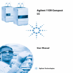
Agilent 1220 Infinity LC
User Manual
Agilent Technologies
Notices
© Agilent Technologies, Inc. 2010
Warranty
No part of this manual may be reproduced
in any form or by any means (including electronic storage and retrieval or translation
into a foreign language) without prior agreement and written consent from Agilent
Technologies, Inc. as governed by United
States and international copyright laws.
The material contained in this document is provided “as is,” and is subject to being changed, without notice,
in future editions. Further, to the maximum extent permitted by applicable
law, Agilent disclaims all warranties,
either express or implied, with regard
to this manual and any information
contained herein, including but not
limited to the implied warranties of
merchantability and fitness for a particular purpose. Agilent shall not be
liable for errors or for incidental or
consequential damages in connection
with the furnishing, use, or performance of this document or of any
information contained herein. Should
Agilent and the user have a separate
written agreement with warranty
terms covering the material in this
document that conflict with these
terms, the warranty terms in the separate agreement shall control.
Manual Part Number
G4280-90010
Edition
07/10
Printed in Germany
Agilent Technologies
Hewlett-Packard-Strasse 8
76337 Waldbronn
This product may be used as a component of an in vitro diagnostic system if the system is registered with
the appropriate authorities and complies with the relevant regulations.
Otherwise, it is intended only for general laboratory use.
receive no greater than Restricted Rights as
defined in FAR 52.227-19(c)(1-2) (June
1987). U.S. Government users will receive
no greater than Limited Rights as defined in
FAR 52.227-14 (June 1987) or DFAR
252.227-7015 (b)(2) (November 1995), as
applicable in any technical data.
Safety Notices
CAUTION
A CAUTION notice denotes a
hazard. It calls attention to an
operating procedure, practice, or
the like that, if not correctly performed or adhered to, could
result in damage to the product
or loss of important data. Do not
proceed beyond a CAUTION
notice until the indicated conditions are fully understood and
met.
Technology Licenses
The hardware and/or software described in
this document are furnished under a license
and may be used or copied only in accordance with the terms of such license.
Restricted Rights Legend
If software is for use in the performance of a
U.S. Government prime contract or subcontract, Software is delivered and licensed as
“Commercial computer software” as
defined in DFAR 252.227-7014 (June 1995),
or as a “commercial item” as defined in FAR
2.101(a) or as “Restricted computer software” as defined in FAR 52.227-19 (June
1987) or any equivalent agency regulation
or contract clause. Use, duplication or disclosure of Software is subject to Agilent
Technologies’ standard commercial license
terms, and non-DOD Departments and
Agencies of the U.S. Government will
WA R N I N G
A WARNING notice denotes a
hazard. It calls attention to an
operating procedure, practice,
or the like that, if not correctly
performed or adhered to, could
result in personal injury or
death. Do not proceed beyond a
WARNING notice until the indicated conditions are fully understood and met.
1220 Infinity LC
In This Book
In This Book
This manual contains information on how to use, maintain, repair and
upgrade the Agilent 1220 Infinity LC System.
1 Introduction
This chapter provides an overview of the Agilent 1220 Infinity LC available
configurations, site requirements and specifications.
2 Installation
This chapter provides an overview on shipment content and installation.
3 Agilent 1220 Infinity LC Description
This chapter provides general information about the functionality and use of
the Agilent 1220 Infinity LC system and its components.
4 Test Functions and Calibration
This chapter describes the tests, calibrations and tools that are available with
the Instrument Utilities software or the Lab Advisor.
5 Error Information
This chapter provides information on the error messages that might be
displayed, and gives the possible causes and suggestions on their solutions.
6 Preventive Maintenance and Repair
Preventive Maintenance (PM) is an Agilent Technologies recommended
procedure designed to reduce the likelihood of electro-mechanical failures.
Failure to perform preventive maintenance may reduce the long-term
reliability of your Agilent 1220 Infinity LC.
1220 Infinity LC
3
Contents
Contents
1 Introduction
7
Agilent 1220 Infinity LC Configurations
Site Requirements 9
Physical Specifications 12
Performance Specifications 13
2 Installation
8
17
Unpacking Your System 18
LAN Configuration 22
3 Agilent 1220 Infinity LC Description
Agilent 1220 Infinity LC electronics
Solvent Delivery System 39
Injection System 48
Column Oven 62
Detector 63
4 Test Functions and Calibration
67
Agilent 1220 Infinity LC System
Solvent Delivery System 72
Autosampler 75
Column Oven 82
Detector 84
69
5 Error Information
37
38
95
What are Error Messages? 98
General Error Messages 99
Pump Error Messages 105
Autosampler Error Messages 117
Detector Error Messages 126
4
1220 Infinity LC
Contents
6 Preventive Maintenance and Repair
135
PM Scope of Work and Checklist 137
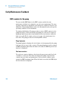
Early Maintenance Feedback 138
Solvent Delivery System 141
Manual Injector 160
Autosampler 164
Detector 184
Algae Growth in HPLC Systems 195
7 Parts for Maintenance and Repair
Agilent 1220 Infinity LC System
Solvent Delivery System 200
Injection System 208
Column Oven 215
Detector 216
197
198
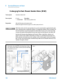
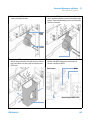
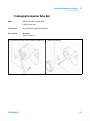
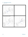
8 Upgrading the Agilent 1220 Infinity LC
Oven Upgrade
9 Appendix
219
220
221
General Safety Information 222
Solvent Information 225
Radio Interference 227
UV Radiation 228
Sound Emission 229
The Waste Electrical and Electronic Equipment (WEEE) Directive
(2002/96/EC) 230
Declaration of Conformity for HOX2 Filter 231
Agilent Technologies on Internet 232
1220 Infinity LC
5
Contents
6
1220 Infinity LC
1220 Infinity LC
1
Introduction
Agilent 1220 Infinity LC Configurations
Site Requirements 9
Power Considerations
Power Cord 10
Bench Space 10
Environment 11
Physical Specifications
8
9
12
Performance Specifications
13
This chapter provides an overview of the Agilent 1220 Infinity LC available
configurations, site requirements and specifications.
Agilent Technologies
7
1
Introduction
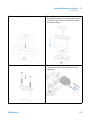
Agilent 1220 Infinity LC Configurations
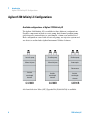
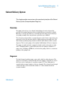
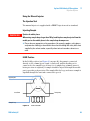
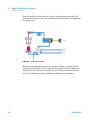
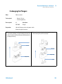
Agilent 1220 Infinity LC Configurations
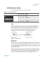
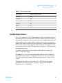
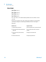
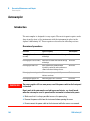
Available configurations of Agilent 1220 Infinity LC
The Agilent 1220 Infinity LC is available in three different configurations.
Possible components include isocratic pump, dual-channel gradient pump
(with degasser), manual injector, autosampler, column oven and detector.
Each configuration comes with at least one pump, one injection system and
one detector and includes Agilent Instrument Utilities Software.
>hdXgVi^Xejbe
<gVY^Zciejbe
<gVY^Zciejbe
BVcjVa^c_ZXidg
BVcjVa^c_ZXidg
6jidhVbeaZg
8dajbcdkZc
KVg^VWaZ
lVkZaZc\i]
YZiZXidg
KVg^VWaZ
lVkZaZc\i]
YZiZXidg
KVg^VWaZ
lVkZaZc\i]
YZiZXidg
<)'-+7
<)'--7
<)'.%7
A Solvent Selection Valve (SSV) Upgrade Kit (G4280-68708) is available.
8
1220 Infinity LC
Introduction
Site Requirements
1
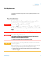
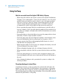
Site Requirements
A suitable environment is important to ensure optimal performance of the
instrument.
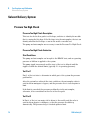
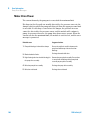
Power Considerations
The Agilent 1220 Infinity LC power supply has wide-ranging capabilities.
Consequently, there is no voltage selector at the instrument.
WA R N I N G
Instrument is partially energized when switched off
The power supply still uses some power even when the power switch on the front
panel is turned OFF. Repair work at the detector can lead to personal injuries, e. g.
shock hazard, when the detector cover is opened and the instrument is connected to
power.
➔ To disconnect the detector from the power line, unplug the power cord.
WA R N I N G
Incorrect line voltage to the instrument
Shock hazard or damage to your instrumentation can result if the devices are
connected to a line voltage higher than specified.
➔ Connect your instrument only to the specified line voltage.
CAUTION
In case of an emergency, it must be possible to disconnect the instrument from the
power line at any time.
Make sure that there is easy access to the power cable of the instrument so that the
instrument can quickly and easily be disconnected from the line voltage.
➔ Provide sufficient space next to the power socket of the instrument to allow the
cable to be unplugged.
1220 Infinity LC
9
1
Introduction
Site Requirements
Power Cord
Different power cords are offered as options with the system. The female ends
of all power cords are identical. The female end plugs into the power-input
socket at the rear left side of the instrument. The male end of each power cord
is different and designed to match the wall socket of a particular country or
region.
WA R N I N G
Absence of ground connection or use of unspecified power cord
The absence of ground connection or the use of unspecified power cord can lead to
electric shock or short circuit.
➔ Never operate your instrument from a power outlet that has no ground connection.
➔ Never use a power cord other than the Agilent Technologies power cord designed
for your region.
WA R N I N G
Use of cables not supplied by Agilent
Using cables that have not been supplied by Agilent Technologies can lead to
damage of the electronic components or personal injury.
➔ Never use cables other than the ones supplied by Agilent Technologies to ensure
proper functionality and compliance with safety or EMC regulations.
Bench Space
The dimensions and weight of the Agilent 1220 Infinity LC allow it to be
placed on almost any desk or laboratory bench. It needs an additional 2.5 cm
(1.0 inch) of space on either side and approximately 8 cm (3.1 inches) at the
rear for air circulation and electric connections.
Make sure that the bench intended to carry the Agilent 1220 Infinity LC is
designed to bear the weight of the instrument.
The Agilent 1220 Infinity LC should be operated upright.
10
1220 Infinity LC
Introduction
Site Requirements
1
Environment
Your Agilent 1220 Infinity LC will work within specifications at ambient
temperatures and relative humidity as described in the following sections.
ASTM drift tests require a temperature change below 2 °C/hour (3.6 °F/hour)
measured over one hour period. Our published drift specification is based on
these conditions. Larger ambient temperature changes will result in larger
drift.
Better drift performance depends on better control of the temperature
fluctuations. To realize the highest performance, minimize the frequency and
the amplitude of the temperature changes to below 1 °C/hour (1.8 °F/hour).
Turbulences around one minute or less can be ignored.
CAUTION
Condensation within the module
Condensation will damage the system electronics.
➔ Do not store, ship or use your module under conditions where temperature
fluctuations could cause condensation within the module.
➔ If your module was shipped in cold weather, leave it in its box and allow it to warm
slowly to room temperature to avoid condensation.
1220 Infinity LC
11
1
Introduction
Physical Specifications
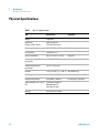
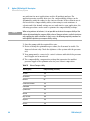
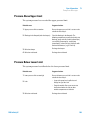
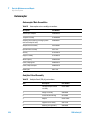
Physical Specifications
Table 1
12
Physical Specifications
Type
Specification
Comments
Weight
30 kg 66 lbs
Dimensions
(height × width × depth)
640×370×420 mm
25.2×14.6×16.5 inches
Line voltage
100 – 240 VAC, ± 10%
Line frequency
50 or 60 Hz, ± 5%
Power consumption
240 VA / 210 W / 717 BTU
Ambient operating
temperature
0–55 °C (32–131 °F)
Ambient non-operating
temperature
-40–70 °C (-4–158 °F)
Humidity
< 95%, at 25–40 °C (77–104 °F) Non-condensing
Operating altitude
Up to 2000 m (6500 ft)
Non-operating altitude
Up to 4600 m (14950 ft)
Safety standards: IEC, CSA, UL,
EN
Installation Category II,
Pollution Degree 2.
For indoor use only.
Housing
All materials recyclable.
Wide-ranging capability
Maximum
For storing the instrument
1220 Infinity LC
Introduction
Performance Specifications
1
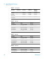
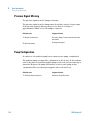
Performance Specifications
Performance Specifications Agilent 1220 Infinity LC
Table 2
Performance Specifications Agilent 1220 Infinity LC
Type
Specification
Safety features
Extensive diagnostics, error detection and
display, leak detection, safe leak handling, leak
output signal for shutdown of pumping system.
Low voltages in major maintenance areas.
Control and data evaluation
Agilent EZChrom Compact, Agilent
ChemStation, Agilent Instrument Utilities,
Agilent Lab Advisor
Communications
Controller-area network (CAN), RS-232C, APG
Remote: ready, start, stop and shut-down
signals, LAN
GLP features
Early maintenance feedback (EMF), electronic
records of maintenance and errors
Performance Specifications Agilent 1220 Infinity LC Pump
Table 3
1220 Infinity LC
Performance Specifications Agilent 1220 Infinity LC Pump
Type
Specification
Hydraulic system
Dual plunger in series pump with proprietary
servo-controlled variable stroke drive, floating
plungers and passive inlet valve
Settable flow range
0.001 – 10 ml/min, in 0.001 ml/min increments
Flow range
0.2 – 10.0 ml/min
13
1
Introduction
Performance Specifications
Table 3
Performance Specifications Agilent 1220 Infinity LC Pump
Type
Specification
Flow precision
<0.07% RSD, or < 0.02 min SD whatever is
greater, based on retention time at constant
room temperature
Flow accuracy
± 1% or 10 µl/min whatever is greater
Pressure
Operating range 0 – 60 MPa (0 – 600 bar,
0 – 8820 psi) up to 5 ml/min
Operating range 0 – 20 MPa (0 – 200 bar,
0 – 2950 psi) up to 10 ml/min
Pressure pulsation
< 2 % amplitude (typically < 1 %), at 1 ml/min
isopropanol, at all pressures > 1 MPa (10 bar)
Compressibility compensation
User-selectable, based on mobile phase
compressibility
Recommended pH range
1.0 – 12.5, solvents with pH < 2.3 should not
contain acids which attack stainless steel
Gradient formation (optional)
Low pressure dual mixing/gradient capability
using proprietary high-speed proportioning valve
Delay volume 800 – 1100 µl, dependent on back
pressure
Composition Range
0 – 95 % or 5 – 100 %, user selectable
Composition Precision
< 0.2 % RSD, at 0.2 and 1 ml/min
Performance Specifications Agilent 1220 Infinity LC Autosampler
Table 4
14
Performance Specifications Agilent 1220 Infinity LC Autosampler
Type
Specification
Pressure
Operating range 0 – 60 MPa (0 – 600 bar,
0 – 8820 psi)
Injection range
0.1 – 100 µl in 0.1 µl increments Up to 1500 µl
with multiple draw (hardware modification
required)
1220 Infinity LC
Introduction
Performance Specifications
Table 4
1
Performance Specifications Agilent 1220 Infinity LC Autosampler
Type
Specification
Replicate injections
1 – 99 from one vial
Precision
< 0.25% RSD from 5 – 100 µl, < 1% RSD 1 – 5 µl
variable volume
Minimum sample volume
1 µl from 5 µl sample in 100 µl microvial, or 1 µl
from 10 µl sample in 300 µl microvial
Carryover
Typically < 0.1%, < 0.05% with external needle
cleaning
Sample viscosity range
0.2 – 50 cp
Sample capacity
100 × 2-ml vials in 1 tray
40 × 2-ml vials in ½ tray
15 × 6-ml vials in ½ tray (Agilent vials only)
Injection cycle time
Typically 50 s depending on draw speed and
injection volume
Performance Specifications Agilent 1220 Infinity LC Column Oven
Table 5
1220 Infinity LC
Performance Specifications Agilent 1220 Infinity LC Column Oven
Type
Specification
Temperature range
5 degrees above ambient to 60 °C
Temperature stability
± 0.15 °C, constant Composition and Flow Rate
Temperature accuracy
± 0.8°C
Column capacity
one 25-cm column
Internal volume
6 µl
15
1
Introduction
Performance Specifications
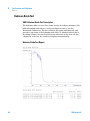
Performance Specifications Agilent 1220 Infinity LC VWD
Table 6
NOTE
16
Performance Specifications Agilent 1220 Infinity LC VWD
Type
Specification
Comment
Detection type
Double-beam photometer
Light source
Deuterium lamp
Wavelength range
190–600 nm
Noise
± 0.35 × 10⁻⁵ AU at 230 nm
2 sec time constant, under
specified conditions
Drift
3 × 10⁻⁴ AU/hr at 254 nm
See NOTE below the table.
Linearity
> 2 AU (5%) upper limit
See NOTE below the table.
Wavelength accuracy
± 1 nm
Self-calibration with deuterium
lines, verification with holmium
oxide filter
Band width
6.5 nm typical
Flow cells
Standard: 14-µl volume, 10-mm
cell path length and 40 bar
(588 psi) maximum pressure
High pressure: 14-µl volume,
10-mm cell path length and
400 bar (5880 psi) maximum
pressure
Semi-micro: 5-µl volume, 6-mm
cell path length and 40 bar
(588 psi) maximum pressure
Micro: 2-µl volume, 3-mm cell
path length and 40 bar (588 psi)
maximum pressure
Can be repaired on component
level
ASTM: “Standard Practice for Variable Wavelength Photometric Detectors Used in Liquid
Chromatography”.Reference conditions: cell path length 10 mm, response time 2 s, flow
1 ml/min LC-grade methanol. Linearity measured with caffeine at 272 nm nm.
1220 Infinity LC
1220 Infinity LC
2
Installation
Unpacking Your System
18
LAN Configuration 22
To do first 22
TCP/IP parameter configuration 24
Configuration Switches 24
Initialization mode selection 25
Link configuration selection 28
Storing the settings permanently with Bootp
Manual Configuration 29
28
This chapter provides an overview on shipment content and installation.
NOTE
To install the Agilent 1220 Infinity LC System, it is highly recommended to follow the
installation instructions step by step.
Agilent Technologies
17
2
Installation
Unpacking Your System
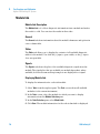
Unpacking Your System
Damaged Packaging
If the delivery packaging shows signs of external damage, please call your
Agilent Technologies sales and service office immediately. Inform your service
representative that the Agilent 1220 Infinity LC may have been damaged
during shipment.
CAUTION
Signs of damage
➔ Do not attempt to install the Agilent 1220 Infinity LC.
Delivery Checklist
Ensure all parts and materials have been delivered with the Agilent 1220
Infinity LC. The delivery checklist is shown below. Please report missing or
damaged parts to your local Agilent Technologies sales and service office.
Table 7
18
Agilent 1220 Infinity Checklist
Description
Quantity
Agilent 1220 Infinity LC
1
Power cable
1
Flow cell
Installed
Instrument Utilities DVD
1
Installation guide
1
Accessory kit (see below)
1
1220 Infinity LC
Installation
Unpacking Your System
2
Accessory Kit Contents for G4286B
Table 8
Accessory Kit Contents for G4286B
Description
Part Number
Quantity
Accessory kit complete
G4286-68755
Fitting, onepiece, fingertight
0100-2562
1
PTFE tubing, 0.052" ID
0890-1195
5m
Flexible tubing (to waste)
0890-1711
3m
Crossover patch cable
5023-0203
1
Waste accessory kit
5062-8535
1
PTFE/silicon septa, 16 mm,
pre-slit (pack of 100)
5188-2758
1
Syringe, 50 µL
5190-1501
1
Syringe, plastic
9301-0411
1
Syringe adapter
9301-1337
1
Screw-cap vial, clear, 6 mL
(pack of 100)
9301-1377
1
Screw caps for 6 mL vials (pack
of 100)
9301-1379
1
Solvent reservoir, 1 L
9301-1420
1
Bottle head assembly
G1311-60003
1
Accessory Kit Contents for G4288B
Table 9
1220 Infinity LC
Accessory Kit Contents for G4288B
Description
Part Number
Quantity
Accessory kit complete
G4288-68755
Fitting, onepiece, fingertight
0100-2562
1
PTFE tubing, 0.052" ID
0890-1195
5m
Flexible tubing (to waste)
0890-1711
3m
19
2
Installation
Unpacking Your System
Table 9
Accessory Kit Contents for G4288B
Description
Part Number
Quantity
Crossover patch cable
5023-0203
1
Waste accessory kit
5062-8535
1
PTFE/silicon septa, 16 mm,
pre-slit (pack of 100)
5188-2758
1
Syringe, 50 µL
5190-1501
1
Syringe, plastic
9301-0411
1
Syringe adapter
9301-1337
1
Screw-cap vial, clear, 6 mL
(pack of 100)
9301-1377
1
Screw caps for 6 mL vials (pack
of 100)
9301-1379
1
Solvent reservoir, 1 L
9301-1420
1
Solvent reservoir, amber, 1 L
9301-1450
1
Bottle head assembly
G1311-60003
2
Accessory Kit Contents for G4290B
Table 10
20
Accessory Kit Contents for G4290B
Description
Part Number
Quantity
Accessory kit complete
G4290-68755
Fitting, onepiece, fingertight
0100-2562
1
PTFE tubing, 0.052" ID
0890-1195
5m
Flexible tubing (to waste)
0890-1711
3m
Crossover patch cable
5023-0203
1
Waste accessory kit
5062-8535
1
Syringe, plastic
9301-0411
1
Syringe adapter
9301-1337
1
1220 Infinity LC
Installation
Unpacking Your System
Table 10
2
Accessory Kit Contents for G4290B
Description
Part Number
Quantity
Solvent reservoir, 1 L
9301-1420
1
Solvent reservoir, amber, 1 L
9301-1450
1
Bottle head assembly
G1311-60003
2
Optional Tool Kit for Agilent 1220 Infinity LC
Table 11
1220 Infinity LC
Optional Tool Kit for Agilent 1220 Infinity LC
Description
Part Number
Quantity
Tool kit complete
G4296-68715
Mounting tool for flangeless
nut
0100-1710
1
Wrench, 1/4 inch to 5/16 inch
8710-0510
2
Wrench, open, 14 mm
8710-1924
1
Wrench, 1/2 inch & 9/16 inch
8720-0025
1
Seal insert tool
01018-23702
1
Hex key, 4 mm, 15 cm long,
T-handle
8710-2392
1
Hex key, 9/64 inch, 15 cm long,
T-handle
8710-2394
1
Hex key, 3 mm, 12 cm long
8710-2411
1
Hex key, 2.5 mm, 12 cm long,
straight handle
8710-2412
1
Screwdriver, Pozidriv shaft
8710-0899
1
21
2
Installation
LAN Configuration
LAN Configuration
To do first
The Agilent 1220 Infinity LC has an on-board LAN communication interface.
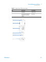
1 Note the MAC (Media Access Control) address for further reference. The
MAC or hardware address of the LAN interfaces is a world wide unique
identifier. No other network device will have the same hardware address.
The MAC address can be found on a label at the rear left side of the
Instrument next to the configuration switch.
EVgicjbWZgd[i]ZYZiZXidg
bV^cWdVgYGZk^h^dc8dYZ!
KZcYdg!NZVgVcYLZZ`
d[VhhZbWanB68VYYgZhh
8djcignd[Dg^\^c
22
1220 Infinity LC
Installation
LAN Configuration
2
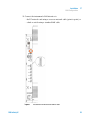
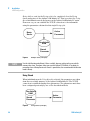
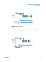
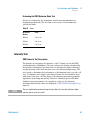
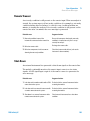
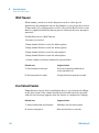
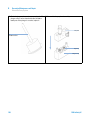
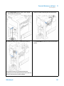
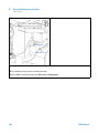
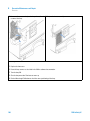
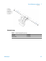
2 Connect the instrument's LAN interface to
• the PC network card using a crossover network cable (point-to-point) or
• a hub or switch using a standard LAN cable.
-
&
Figure 1
1220 Infinity LC
Location of LAN interface and MAC label
23
2
Installation
LAN Configuration
TCP/IP parameter configuration
To operate properly in a network environment, the LAN interface must be
configured with valid TCP/IP network parameters. These parameters are:
• IP address
• Subnet Mask
• Default Gateway
The TCP/IP parameters can be configured by the following methods:
• by automatically requesting the parameters from a network-based BOOTP
Server (using the so-called Bootstrap Protocol)
• by manually setting the parameters using Telnet
The LAN interface differentiates between several initialization modes. The
initialization mode (short form ‘init mode’) defines how to determine the
active TCP/IP parameters after power-on. The parameters may be derived
from a Bootp cycle, non-volatile memory or initialized with known default
values. The initialization mode is selected by the configuration switch.
Configuration Switches
The configuration switch can be accessed at the rear left side of the
instrument.
The Agilent 1220 Infinity LC is shipped with switches 7 and 8 set to ON, which
means that the instrument is set to a default fixed IP address: 192.168.254.11
NOTE
To configure the LAN, SW1 and SW2 must be set to OFF.
Table 12
24
Factory Default Settings
Initialization (‘Init’) Mode
Using Default, switches 7 and 8 set to ON.
Link Configuration
Speed and duplex mode determined by auto-negotiation
1220 Infinity LC
Installation
LAN Configuration
2
Initialization mode selection
The following initialization (init) modes are selectable:
Table 13
Initialization Mode Switches
SW 6
SW 7
SW 8
Init Mode
OFF
OFF
OFF
Bootp
OFF
OFF
ON
Bootp & Store
OFF
ON
OFF
Using Stored
OFF
ON
ON
Using Default
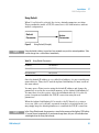
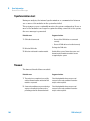
Bootp
When the initialization mode Bootp is selected, the Agilent 1220 Infinity LC
tries to download the parameters from a Bootp Server. The parameters
obtained become the active parameters immediately. They are not stored to
the non-volatile memory of the Agilent 1220 Infinity; therefore, the
parameters are lost with the next power cycle of the instrument.
#PPUQ
4FSWFS
Figure 2
"DUJWF
1BSBNFUFS
Bootp (Principle)
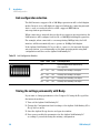
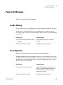
Bootp & Store
When Bootp & Store is selected, the parameters obtained from a Bootp Server
become the active parameters immediately. In addition, they are stored to the
non-volatile memory of the Agilent 1220 Infinity LC. Thus, after a power cycle
they are still available. This enables a kind of bootp once configuration of the
Agilent 1220 Infinity LC.
Example: You may not want to have a Bootp Server active in his network all
the time. But, on the other hand, You may not have any configuration method
other than Bootp. If this is the case you start the Bootp Server temporarily,
power on the Agilent 1220 Infinity LC using the initialization mode
1220 Infinity LC
25
2
Installation
LAN Configuration
Bootp & Store, wait for the Bootp cycle to be completed, close the Bootp
Server and power off the Agilent 1220 Infinity LC. Then you select the Using
Stored initialization mode and power on the Agilent 1220 Infinity LC again.
From now on, you can establish the TCP/IP connection to the instrument
using the parameters obtained in that single Bootp cycle.
"DUJWF
1BSBNFUFS
#PPUQ
4FSWFS
/PO7PMBUJMF
3".
4UPSFE
1BSBNFUFS
Figure 3
NOTE
Bootp & Store (Principle)
Use the initialization mode Bootp & Store carefully, because writing to the non-volatile
memory takes time. Therefore, when you want the Agilent 1220 Infinity LC to obtain its
parameters from a Bootp Server each time it is powered on, the recommended initialization
mode is Bootp.
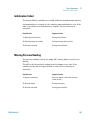
Using Stored
When initialization mode Using Stored is selected, the parameters are taken
from the non-volatile memory of the Agilent 1220 Infinity LC. The TCP/IP
connection is established using these parameters. The parameters must have
been configured previously by one of the described methods.
/PO7PMBUJMF
3".
4UPSFE
1BSBNFUFS
Figure 4
26
"DUJWF
1BSBNFUFS
Using Stored (Principle)
1220 Infinity LC
Installation
LAN Configuration
2
Using Default
When Using Default is selected, the factory default parameters are taken.
These parameters enable a TCP/IP connection to the LAN interface without
further configuration.
%FGBVMU
1BSBNFUFS
Figure 5
NOTE
"DUJWF
1BSBNFUFS
Using Default (Principle)
Using the default address in your local area network may result in network problems. Take
care to change it to a valid address immediately.
Table 14
Using Default Parameters
IP address:
192.168.254.11
Subnet Mask:
255.255.255.0
Default Gateway
not specified
Since the default IP address is a so-called local address, it is not routed by any
network device. Thus, the PC and the Agilent 1220 Infinity LC must reside in
the same subnet.
You may open a Telnet session using the default IP address and change the
parameters stored in the non-volatile memory of the Agilent 1220 Infinity LC.
You may then close the session, select the initialization mode Using Stored,
power-on again and establish the TCP/IP connection using the new
parameters.
When the Agilent 1220 Infinity LC is wired to the PC directly (e.g. using a
cross-over cable or a local hub), separated from the local area network, you
may simply keep the default parameters to establish the TCP/IP connection.
NOTE
1220 Infinity LC
In the Using Default mode, the parameters stored in the memory of the Agilent 1220 Infinity
LC are not cleared automatically. If you do not change them, they are still available when
switching back to the Using Stored mode.
27
2
Installation
LAN Configuration
Link configuration selection
The LAN interface supports 10 or 100 Mbps operation in full- or half-duplex
modes. In most cases, full-duplex is supported when the connecting network
device - such as a network switch or hub - supports IEEE 802.3u
auto-negotiation specifications.
When connecting to network devices that do not support auto-negotiation, the
LAN interface will configure itself for 10- or 100-Mbps half-duplex operation.
For example, when connected to a non-negotiating 10-Mbps hub, the LAN
interface will be automatically set to operate at 10-Mbps half-duplex.
If the Agilent 1220 Infinity LC is not able to connect to the network through
auto-negotiation, you can manually set the link operating mode using link
configuration switches on the Agilent 1220 Infinity LC.
Table 15
Link Configuration Switches
SW 3
SW 4
SW 5
Link Configuration
OFF
-
-
speed and duplex mode determined by
auto-negotiation
ON
OFF
OFF
manually set to 10 Mbps, half-duplex
ON
OFF
ON
manually set to 10 Mbps, full-duplex
ON
ON
OFF
manually set to 100 Mbps, half-duplex
ON
ON
ON
manually set to 100 Mbps, full-duplex
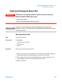
Storing the settings permanently with Bootp
If you want to change parameters of the Compact LC using the Bootp follow
the instructions below.
1 Turn off the Agilent 1220 Infinity LC.
2 Change the Configuration Switch settings of the Agilent 1220 Infinity LC to
Bootp & Store mode.
3 Start the Agilent Bootp Service and open its window.
4 If necessary, modify the parameters for the Agilent 1220 Infinity LC
according to your needs using the existing configuration.
28
1220 Infinity LC
Installation
LAN Configuration
2
5 Press OK to exit the Bootp Manager.
6 Turn on the Agilent 1220 Infinity LC and view the Bootp Server window.
After some time the Agilent Bootp Service will display the request from the
LAN interface. The parameters are now stored permanently in the
non-volatile memory of the Compact LC.
7 Close the Agilent Bootp Service and turn off the Agilent 1220 Infinity LC.
8 Change the Configuration Switch settings of the Agilent 1220 Infinity LC to
Using Stored mode.
9 Power cycle the Agilent 1220 Infinity LC.
The Agilent 1220 Infinity LC can now be accessed via LAN without the
Agilent Bootp Service.
Manual Configuration
Manual configuration alters the set of parameters stored in the non-volatile
memory only of the Agilent 1220 Infinity LC; it does not affect the currently
active parameters. Therefore, manual configuration can be done at any time. A
power cycle is mandatory to activate the stored parameters if the initialization
mode selection switches allow it.
I:AC:I
HZhh^dc
Cdc"KdaVi^aZ
G6B
HidgZY
EVgVbZiZg
Figure 6
1220 Infinity LC
Manual Configuration (Principle)
29
2
Installation
LAN Configuration
With Telnet
Whenever a TCP/IP connection to the Agilent 1220 Infinity LC is possible
(TCP/IP parameters set by any method), the parameters may be altered by
opening a Telnet session.
1 Open the system (DOS) prompt window by clicking on Windows START
button and select Run.... Type
cmd and click OK.
2 Type the following at the system (DOS) prompt:
• c:\>telnet <IP address> or
• c:\>telnet <host name>
Figure 7
Telnet - Starting a session
where <IP address> may be the assigned address from a Bootp cycle or the
default IP address.
When the connection was established successfully, the Agilent 1220 Infinity
LC responds with the following:
Figure 8
A connection to the module is made
3 Type
? and press enter to see the available commands.
30
1220 Infinity LC
Installation
LAN Configuration
Figure 9
Table 16
2
Telnet Commands
Telnet Commands
Value
Description
?
displays syntax and descriptions of commands
/
displays current LAN settings
ip <x.x.x.x>
sets new ip address
sm <x.x.x.x>
sets new subnet mask
gw <x.x.x.x>
sets new default gateway
exit
exits shell and saves all changes
4 To change a parameter, use the syntax:
• parameter value
for example:
ip 134.40.27.230
Then press [Enter], where parameter refers to the configuration parameter
you are defining, and value refers to the definitions you are assigning to
that parameter. Each parameter entry is followed by a carriage return.
1220 Infinity LC
31
2
Installation
LAN Configuration
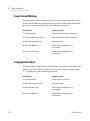
5 Use the “/” and press Enter to list the current settings.
JOGPSNBUJPOBCPVUUIF-"/JOUFSGBDF
."$BEESFTTJOJUJBMJ[BUJPONPEF
*OJUJBMJ[BUJPONPEFJT6TJOH4UPSFE
BDUJWF5$1*1TFUUJOHT
5$1*1TUBUVTIFSFSFBEZ
DPOOFDUFEUP1$XJUIDPOUSPMMFS
TPGUXBSFFH"HJMFOU$IFN4UBUJPO
IFSFOPUDPOOFDUFE
Figure 10
Telnet - Current settings in "Using Stored" mode
6 Change the IP address (in this example 134.40.27.99) and type “/” to list
current settings.
X]Vc\Zd[>EhZii^c\id
>c^i^Va^oVi^dcbdYZ^hJh^c\HidgZY
VXi^kZI8E$>EhZii^c\h
hidgZYI8E$>EhZii^c\h^ccdc"kdaVi^aZbZbdgn
XdccZXiZYidE8l^i]XdcigdaaZg
hd[ilVgZZ#\#6\^aZci8]ZbHiVi^dc!
]ZgZcdiXdccZXiZY
Figure 11
32
Telnet - Change IP settings
1220 Infinity LC
2
Installation
LAN Configuration
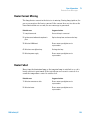
7 When you have finished typing the configuration parameters, type
exit and press [Enter] to exit with storing parameters.
Figure 12
NOTE
Closing the Telnet Session
If the Initialization Mode Switch is changed now to “Using Stored” mode, the instrument
will take the stored settings when the module is re-booted. In the example above it would
be 134.40.27.99.
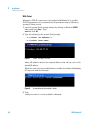
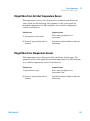
Automatic configuration with Bootp
When automatic configuration with Bootp is selected and the LAN interface is
powered on, it broadcasts a BOOTP (Bootstrap Protocol) request that contains
its MAC (hardware) address. A BOOTP server daemon searches its database
for a matching MAC address, and if successful, sends the corresponding
configuration parameters to the compact LC as a BOOTP reply. These
parameters become the active TCP/IP parameters immediately and the TCP/IP
connection can be established.
Configuring the Agilent Bootp service program
NOTE
The examples shown in this chapter will not work in your environment. You need your own
IP address, Subnet Mask and Gateway address.
NOTE
Ensure that the Agilent 1220 Infinity LC configuration switch is set to either Bootp or Bootp
& Store.
1220 Infinity LC
33
2
Installation
LAN Configuration
NOTE
Ensure that your instrument is powered off.
NOTE
If the Agilent Bootp Service program is not already installed on your PC, install it from the
folder \Bootp on your software CD-ROM.
1 The Agilent Bootp Service is placed in the start-up group and is started
automatically during the boot process of the PC.
2 Open the Bootp Settings window and enter the default settings for your
setup.
3 Launch the Manager.
The Bootp Manager screen opens, showing all network hardware that has
been added (initially empty).
4 Click Add to enter the enter the module-specific information:
• MAC address (from the label on the instrument)
• host name
• IP address
• comment (instrument name/location)
• subnet mask (if different)
• gateway (if required)
5 Click OK.
The parameters are added to the Bootp Manager and to the TabFile.
6 Click Exit Manager and OK to exit the Agilent Bootp Service.
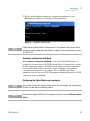
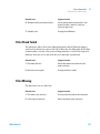
7 Turn on the instrument, wait about 30-60 seconds and view the LogFile (see
Figure 13 on page 35).
It should display the request from the detector with the hardware (MAC)
address.
34
1220 Infinity LC
Installation
LAN Configuration
2
%'$%($%*&+/((/*+EB
HiVijh/7DDIEGZfjZhigZXZ^kZYVidjiZgbdhiaVnZg
HiVijh/7DDIEGZfjZhigZXZ^kZY[gdb]VgYlVgZVYYgZhh/%%(%9(%6%-(HiVijh/[djcY&()#)%#',#.*L69>&&,&/
HiVijh/=dhi>E6YYgZhh^h/&()#)%#'.#*+
HiVijh/GZeanid7DDIEGZfjZhi]VhWZZchZci
HiVijh/7DDIEGZfjZhi[^c^h]ZYegdXZhh^c\VidjiZgbdhiaVnZg
Figure 13
NOTE
1220 Infinity LC
LogFile - the detector has received the parameter
When using this Bootp mode, the parameters are not written into the non-volatile memory
of the detector.
35
2
36
Installation
LAN Configuration
1220 Infinity LC
1220 Infinity LC
3
Agilent 1220 Infinity LC Description
Agilent 1220 Infinity LC electronics
Solvent Delivery System 39
Overview 39
Degasser 39
Principles of Operation 40
Compressibility Compensation
Variable Stroke Volume 45
Using the Pump 46
38
43
Injection System 48
Manual Injector 48
Autosampler 51
Column Oven
Detector
62
63
This chapter provides general information about the functionality and use of
the Agilent 1220 Infinity LC system and its components.
Agilent Technologies
37
3
Agilent 1220 Infinity LC Description
Agilent 1220 Infinity LC electronics
Agilent 1220 Infinity LC electronics
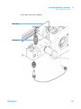
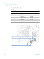
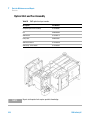
All electrical connectors are placed on the rear left side of the instrument.
Available connectors:
• Power connector, female end
• LAN connector (Agilent 1220 Infinity LC to controlling PC)
• CAN connectors (Agilent 1220 Infinity LC to additional Agilent 1200 Series
Module)
• USB connector (for future use)
• RS232 connector
• APG Remote connector
• 12V DC Output
• 8 bit configuration switch (see “LAN Configuration” on page 22)
• 5 Main Board fuses 250Vac, T3.15A 2110-1417
• Fuse F1 (Degasser, Pump, Injector Motors)
• Fuse F2 (Injector sensors, Column Oven, Ext 24V Connector)
• Fuse F3 (Processor Core, +5V, +15V, -15V supply on Mainboard)
• Fuse F4 (VWD incl. D2-Lamp)
• Fuse F5 (VWD Heater, FAN)
Next to each fuse is a LED. Red LED indicates the fuse is blown.
If one of the fuses is blown, the green LED of the power switch flashes.
• Fuse Netfilter 250Vac, T10AH 2110-1004
38
1220 Infinity LC
3
Agilent 1220 Infinity LC Description
Solvent Delivery System
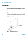
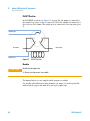
Solvent Delivery System
This chapter provides an overview on the operational principles of the Solvent
Delivery System (Pump and optional Degasser).
Overview
The pump is based on a two-channel, dual-plunger in-series design that
provides all essential functions that a solvent delivery system has to fulfill.
Metering of solvent and delivery to the high-pressure side are performed by
one pump assembly that can generate a pressure up to 600 bar.
The solvents are degassed by a vacuum degasser, and solvent compositions are
generated on the low-pressure side by a high-speed proportioning valve. The
dual-channel gradient pump includes a built-in dual-channel online vacuum
degasser. The isocratic pump of the Agilent 1220 Infinity LC has no degasser.
The pump assembly includes a pump head with an inlet valve and an outlet
valve. A damping unit is connected between the two plunger chambers. A
purge valve, including a PTFE frit, is fitted at the pump outlet for convenient
priming of the pump head.
Degasser
The dual-channel gradient pump comes with a built-in online degasser. The
degasser is switched on automatically when the pump is switched on, even if
the flow is set to 0 mL/min. A constant vacuum of 75 Torr (100 mbar) is
created in the vacuum chamber of the two channels. The solvent flows through
a Teflon AF tube, with an internal volume of 1.5 mL/channel inside the
vacuum chamber.
1220 Infinity LC
39
3
Agilent 1220 Infinity LC Description
Solvent Delivery System
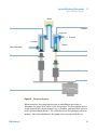
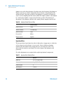
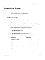
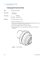
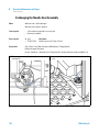
Principles of Operation
The liquid runs from the solvent reservoir through the degasser to the DCGV,
and from there to the inlet valve. The pump assembly comprises two
substantially identical plunger/chamber units. Both plunger/chamber units
comprise a ball-screw drive and a pump head containing one reciprocating
sapphire plunger.
A servo-controlled variable-reluctance motor drives the two ball-screw drives
in opposite directions. The gears for the ball-screw drives have different
circumferences (ratio 2:1), allowing the first plunger to move at twice the
speed of the second plunger. The solvent enters the pump head close to the
bottom limit and leaves it at its top. The outer diameter of the plunger is
smaller than the inner diameter of the pump head chamber, allowing the
solvent to fill the gap in between. The first plunger has a stroke volume in the
range of 20–100 µL depending on the flow rate. The microprocessor controls
all flow rates in a range of 1 µL–10 mL/min. The inlet of the first
plunger/chamber unit is connected to the inlet valve, which is opened or
closed allowing solvent to be drawn into the first plunger pump unit.
The outlet of the first plunger/chamber unit is connected through the outlet
ball valve and the damping unit to the inlet of the second plunger/chamber
unit. The outlet of the purge valve assembly is then connected to the
chromatographic system.
40
1220 Infinity LC
Agilent 1220 Infinity LC Description
Solvent Delivery System
3
9VbeZg
8]VbWZg'
8]VbWZg&
Ejg\ZkVakZ
>caZikVakZ
IdXdajbc
DjiaZi
kVakZ
IdlVhiZ
;gdbhdakZciWdiiaZ
HZVa
Eajc\Zg&
Eajc\Zg'
7VaahXgZlYg^kZ
<ZVg
Bdidgl^i]ZcXdYZg
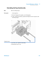
Figure 14
Principle of the pump
When turned on, the pump runs through an initialization procedure to
determine the upper dead center of the first plunger. The first plunger moves
slowly upwards into the mechanical stop of chamber, and from there it moves
back a predetermined distance. The controller stores this plunger position in
memory. After this initialization, the pump starts operation with the set
1220 Infinity LC
41
3
Agilent 1220 Infinity LC Description
Solvent Delivery System
parameters. The inlet valve is opened and the down-moving plunger draws
solvent into the first chamber. At the same time, the second plunger moves
upwards, delivering into the system. After a controller-defined stroke length
(depending on the flow rate), the drive motor is stopped and the inlet valve is
closed. The motor direction is reversed and moves the first plunger up until it
reaches the stored upper limit and at the same time moves the second plunger
downwards. The sequence then starts again, moving the plungers up and down
between the two limits. During the up movement of the first plunger, the
solvent in the chamber is pushed through the outlet ball valve into the second
chamber. The second plunger draws in half of the volume displaced by the first
plunger and the remaining half volume is directly delivered into the system.
During the drawing stroke of the first plunger, the second plunger delivers the
drawn volume into the system.
For solvent compositions from the solvent bottles A and B, the controller
divides the length of the intake stroke into certain fractions in which the
gradient valve connects the specified solvent channel to the pump input.
Table 17
Isocratic pump details
Dead volume
800 – 1100 µL, depending on back pressure
Materials in contact with mobile phase
Pump head
SST, gold, sapphire, ceramic
Active inlet valve
SST, gold, sapphire, ruby, ceramic, PTFE
Outlet valve
SST, gold, sapphire, ruby
Adapter
SST, gold
Purge valve
SST, gold, PTFE, ceramic, PEEK
Degasser chamber
TFE/PDD Copolymer, FEP, PEEK, PPS
Table 18
Gradient Pump Details
Delay volume
800 – 1100 µL, dependent on back pressure
Materials in contact with mobile phase
42
MCGV
PTFE
Pump head
SST, gold, sapphire, ceramic
1220 Infinity LC
3
Agilent 1220 Infinity LC Description
Solvent Delivery System
Table 18
Gradient Pump Details
Active inlet valve
SST, gold, sapphire, ruby, ceramic, PTFE
Outlet valve
SST, gold, sapphire, ruby
Adapter
SST, gold
Purge valve
SST, gold, PTFE, ceramic, PEEK
Damping unit
Gold, SST
Degasser chamber
TFE/PDD Copolymer, FEP, PEEK, PPS
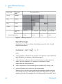
Compressibility Compensation
Principles of compressibility compensation
The compressibility of the solvents in use affects retention-time stability when
the back pressure in the system changes (for example, ageing of the column).
To minimize this effect, the pump provides a compressibility compensation
feature that optimizes the flow stability according to the solvent type. The
compressibility compensation is set to a default value and can be changed
through the user interface.
Without compressibility compensation, the following happens during a stroke
of the first plunger: the pressure in the plunger chamber increases and the
volume in the chamber is compressed, depending on backpressure and solvent
type. The volume displaced into the system is reduced by the compressed
volume.
When a compressibility value is set, the processor calculates a compensation
volume that is depending on the backpressure in the system and the selected
compressibility. This compensation volume is added to the normal stroke
volume and compensates for the previously described loss of volume during
the delivery stroke of the first plunger.
Optimizing the compressibility compensation setting
The default compressibility compensation setting is 46 × 10-6 /bar. This setting
represents an average value. Under normal conditions, the default setting
reduces the pressure pulsation to values (below 1% of system pressure) that
1220 Infinity LC
43
3
Agilent 1220 Infinity LC Description
Solvent Delivery System
are sufficient for most applications and for all gradient analyses. For
applications using sensitive detectors, the compressibility settings can be
optimized by using the values for the various solvents. If the solvent in use is
not listed in the compressibility tables, when using isocratic mixtures of
solvents and if the default settings are not sufficient for your application, the
following procedure can be used to optimize the compressibility settings.
NOTE
When using mixtures of solvents, it is not possible to calculate the compressibility of the
mixture by interpolating the compressibility values of the pure solvents used in that mixture
or by applying any other calculation. In these cases, the following empirical procedure has
to be applied to optimize your compressibility setting.
1 Start the pump with the required flow rate.
2 Before starting the optimization procedure, the flow must be stable. Use
degassed solvent only. Check the tightness of the system with the pressure
test.
3 Your pump must be connected to control software with which the pressure
and %-ripple can be monitored.
4 The compressibility compensation setting that generates the smallest
pressure ripple is the optimum value for your solvent composition.
Table 19
44
Solvent Compressibility
Solvent (pure)
Compressibility (10-6/bar)
Acetone
126
Acetonitrile
115
Benzene
95
Carbon tetrachloride
110
Chloroform
100
Cyclohexane
118
Ethanol
114
Ethyl acetate
104
Heptane
120
Hexane
150
1220 Infinity LC
Agilent 1220 Infinity LC Description
Solvent Delivery System
Table 19
3
Solvent Compressibility
Solvent (pure)
Compressibility (10-6/bar)
Isobutanol
100
Isopropanol
100
Methanol
120
1-Propanol
100
Toluene
87
Water
46
Variable Stroke Volume
Due to the compression of the pump-chamber volume, each plunger stroke of
the pump generates a small pressure pulsation, influencing the flow ripple of
the pump. The amplitude of the pressure pulsation is dependent mainly on the
stroke volume and the compressibility compensation for the solvent in use.
Small stroke volumes generate pressure pulsations of smaller amplitude than
larger stroke volumes at the same flow rate. In addition, the frequency of the
pressure pulsations are higher. This decreases the influence of flow pulsations
on quantitative results.
In gradient mode, smaller stroke volumes result in less flow ripple and
improve composition ripple.
The pump uses a processor-controlled spindle system to drive its plungers.
The normal stroke volume is optimized for the selected flow rate. Low flow
rates use a small stroke volume, while higher flow rates use a larger stroke
volume.
When the stroke volume for the pump is set to AUTO mode, the stroke is
optimized for the flow rate in use. A change to larger stroke volumes is
possible but not recommended.
1220 Infinity LC
45
3
Agilent 1220 Infinity LC Description
Solvent Delivery System
Using the Pump
Hints for successful use of the Agilent 1220 Infinity LC pump
• When using salt solutions and organic solvents in the Agilent 1120 Infinity
LC pump, it is recommended to connect the salt solution to one of the lower
gradient valve ports and the organic solvent to one of the upper gradient
valve port. It is best to have the organic channel directly above the salt
solution channel. Regular flushing with water of all DCGV channels is
recommended to remove all possible salt deposits in the valve ports.
• Before operating the pump, flush the vacuum degasser (optional) with at
least two volumes (3 ml), especially when the pump has been turned off for
some time (for example, overnight) and volatile solvent mixtures are used in
the channels.
• Prevent blocking of solvent inlet filters (never use the pump without solvent
inlet filter). Growth of algae should be avoided.
• Check the purge valve frit and column frit regularly. A blocked purge valve
frit can be identified by black or yellow layers on its surface, or by a
pressure greater than 10 bar when pumping distilled water at a rate of
5 ml/min with an open purge valve.
• When using the pump at low flow rates (for example, 0.2 ml/min), check all
1/16-inch fittings for any signs of leaks.
• When exchanging the pump seals, also exchange the purge valve frit.
• When using buffer solutions, flush the system with water before switching
it off.
• Check the pump plungers for scratches when changing the plunger seals.
Scratched plungers will lead to micro leaks and will decrease the lifetime of
the seal.
• After changing the plunger seals, pressurize the system according to the
wear-in procedure.
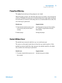
Preventing blockage of solvent filters
Contaminated solvents or algae growth in the solvent bottle will reduce the
lifetime of the solvent filter and will influence the performance of the pump.
This is especially true for aqueous solvents or phosphate buffers (pH 4 to 7).
The following suggestions will prolong the lifetime of the solvent filter and will
maintain the performance of the pump.
46
1220 Infinity LC
3
Agilent 1220 Infinity LC Description
Solvent Delivery System
• Use a sterile, if possible amber, solvent bottle to slow down algae growth.
• Filter solvents through filters or membranes that remove algae.
• Exchange solvents every two days, or refilter.
• If the application permits, add 0.0001-0.001M sodium azide to the solvent.
• Place a layer of argon on top of your solvent.
• Avoid exposure of the solvent bottle to direct sunlight.
NOTE
1220 Infinity LC
Never use the system without a solvent filter installed.
47
3
Agilent 1220 Infinity LC Description
Injection System
Injection System
This chapter provides an overview of the operational principles of the Injection
Systems: Manual Injector and Autosampler.
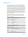
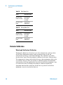
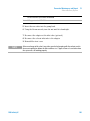
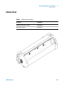
Manual Injector
The Agilent 1220 Infinity LC manual injector uses a Rheodyne, 6-port sample
injection valve (part number 5067-4202). Sample is loaded into the external
20-µl sample loop through the injection port at the front of the valve. The valve
has a PEEK™ injection seal. A make-before-break passage in the stator
ensures flow is not interrupted when the valve is switched between the
INJECT and LOAD positions, and back again.
AdVYedh^i^dc
>c_ZXiedh^i^dc
Figure 15
48
Rheodyne 6-port sample injection valve
1220 Infinity LC
3
Agilent 1220 Infinity LC Description
Injection System
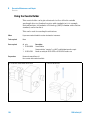
Using the Manual Injector
The Injection Seal
The manual injector is supplied with a PEEK™ injection seal as standard.
Injecting Sample
WA R N I N G
Ejection of mobile phase
When using sample loops larger than 100 µl, mobile phase may be ejected from the
needle port as the mobile phase in the sample loop decompresses.
➔ Please observe appropriate safety procedures (for example, goggles, safety gloves
and protective clothing) as described in the material handling and safety data sheet
supplied by the solvent vendor, especially when toxic or hazardous solvents are
used.
LOAD Position
In the LOAD position (see Figure 16 on page 49), the pump is connected
directly to the column (ports 2 and 3 connected), and the needle port is
connected to the sample loop. At least 2 to 3 sample-loop volumes (more if
better precision is required) of sample should be injected through the needle
port to provide good precision. The sample fills the loop, and excess sample is
expelled through the vent tube connected to port 6.
CZZYaZedgi
LVhiZ
idXdajbc
[gdbejbe
HVbeaZadde
Figure 16
1220 Infinity LC
LOAD Position
49
3
Agilent 1220 Infinity LC Description
Injection System
INJECT Position
In the INJECT position (see Figure 17 on page 50), the pump is connected to
the sample loop (ports 1 and 2 connected). All of the sample is washed out of
the loop onto the column. The needle port is connected to the vent tube (port
5).
CZZYaZedgi
LVhiZ
[gdbejbe
idXdajbc
HVbeaZadde
Figure 17
INJECT Position
Needles
CAUTION
Needle can damage valve
➔ Always use the correct size needle.
The manual injector is not supplied with syringes or needles.
Use needles with 0.028-inch outer diameter (22 gauge) × 2-inch long needle,
without electro-taper, and with 90° point style (square tip).
50
1220 Infinity LC
3
Agilent 1220 Infinity LC Description
Injection System
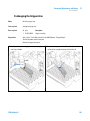
Autosampler
Introduction to the Autosampler
Three sample-rack sizes are available for the autosampler. The standard
full-size rack holds 100 × 1.8 ml vials, while the two half-size racks provide
space for 40 × 1.8 ml vials and 15 × 6 ml vials respectively. Any two half-size
rack trays can be installed in the autosampler simultaneously. The analytical
head device provides injection volumes from 0.1 – 100 µl.
The autosamplers transport mechanism uses an X-Z-Theta movement to
optimize vial pick-up and return. Vials are picked up by the gripper arm, and
positioned below the sampling unit. The gripper transport mechanism and
sampling unit are driven by motors. Movement is monitored by optical sensors
and optical encoders to ensure correct operation. The metering device is
always flushed after injection to ensure minimum carry-over.
The six-port injection valve unit (only 5 ports are used) is driven by a
high-speed hybrid stepper motor. During the sampling sequence, the valve unit
bypasses the autosampler, and directly connects the flow from the pump to the
column. During injection and analysis, the valve unit directs the flow through
the autosamplers which ensures that the sample is injected completely into
the column, and that any sample residue is removed from the metering unit
and needle from before the next sampling sequence begins.
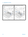
Sampling Sequence
The movements of the autosampler components during the sampling sequence
are monitored continuously by the processor. The processor defines specific
time windows and mechanical ranges for each movement. If a specific step of
the sampling sequence can’t be completed successfully, an error message is
generated.
Solvent is bypassed from the autosamplers by the injection valve during the
sampling sequence. The sample vial is selected by a gripper arm from a static
sample rack. The gripper arm places the sample vial below the injection
needle. The required volume of sample is drawn into the sample loop by the
metering device. Sample is applied to the column when the injection valve
returns to the mainpass position at the end of the sampling sequence.
The sampling sequence occurs in the following order:
1 The injection valve switches to the bypass position.
1220 Infinity LC
51
3
Agilent 1220 Infinity LC Description
Injection System
2 The plunger of the metering device moves to the initialization position.
3 The gripper arm selects the vial. At the same time, the needle lifts out of the
seat.
4 The gripper arm places the vial below the needle.
5 The needle lowers into the vial.
6 The metering device draws the defined sample volume.
7 The needle lifts out of the vial.
8 If the automated needle wash is selected, the gripper arm replaces the
sample vial, positions the wash vial below the needle, lowers the needle into
the vial, then lifts the needle out of the wash vial.
9 The gripper arm checks if the safety flap is in position.
10 The gripper arm replaces the vial. Simultaneously, the needle lowers into
the seat.
11 The injection valve switches to the mainpass position.
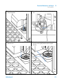
Injection Sequence
Before the start of the injection sequence, and during an analysis, the injection
valve is in the mainpass position. In this position, the mobile phase flows
through the autosamplers metering device, sample loop, and needle, ensuring
all parts in contact with sample are flushed during the run, thus minimizing
carry-over.
52
1220 Infinity LC
Agilent 1220 Infinity LC Description
Injection System
Figure 18
3
Mainpass Position
When the sample sequence begins, the valve unit switches to the bypass
position. Solvent from the pump enters the valve unit at port 1, and flows
directly to the column through port 6.
Figure 19
1220 Infinity LC
Bypass Position
53
3
Agilent 1220 Infinity LC Description
Injection System
Next, the needle is raised, and the vial is positioned below the needle. The
needle moves down into the vial, and the metering unit draws the sample into
the sample loop.
Figure 20
Drawing the Sample
When the metering unit has drawn the required volume of sample into the
sample loop, the needle is raised, and the vial is replaced in the sample tray.
The needle is lowered into the needle seat, and the injection valve switches
back to the mainpass position, flushing the sample onto the column .
54
1220 Infinity LC
3
Agilent 1220 Infinity LC Description
Injection System
Figure 21
Mainpass Position (Sample Injection)
Sampling Unit
The sampling unit comprises three main assemblies: needle drive, metering
device, and injection valve.
NOTE
The replacement sampling unit excludes the injection valve and metering head assemblies.
Needle-Drive
The needle movement is driven by a stepper motor connected to the spindle
assembly by a toothed belt. The circular motion of the motor is converted to
linear motion by the drive nut on the spindle assembly. The upper and lower
needle positions are detected by reflection sensors on the sampling unit flex
board, while the needle-in-vial position is determined by counting the motor
steps from the upper needle-sensor position.
Analytical head
The analytical head is driven by the stepper motor connected to the drive shaft
by a toothed belt. The drive nut on the spindle converts the circular movement
of the spindle to linear motion. The drive nut pushes the sapphire plunger
against the tension of the spring into the analytical head. The base of the
1220 Infinity LC
55
3
Agilent 1220 Infinity LC Description
Injection System
plunger sits on the large bearing of the drive nut, which ensures the plunger is
always centered. A ceramic ring guides the movement of the plunger in the
analytical head. The home position of the plunger is sensed by an infra-red
sensor on the sampling unit flex board, while the sample volume is determined
by counting the number of steps from the home position. The backward
movement of the plunger (driven by the spring) draws sample from the vial.
Table 20
Analytical Head Technical Data
Standard (100 µl)
Number of steps
15000
Volume resolution
7 nl/motor step
Maximum stroke
100 µl
Pressure limit
600 bar
Plunger material
Sapphire
Injection-Valve
The two-position 6-port injection valve is driven by a stepper motor. Only five
of the six ports are used (port 3 is not used). A lever/slider mechanism
transfers the movement of the stepper motor to the injection valve. Two
microswitches monitor switching of the valve (bypass and mainpass end
positions).
No valve adjustments are required after replacing internal components.
Table 21
Injection-Valve Technical Data
Standard
56
Motor type
4 V, 1.2 A stepper motor
Seal material
Vespel™ (Tefzel™ available)
Number of ports
6
Switching time
< 150 ms
1220 Infinity LC
3
Agilent 1220 Infinity LC Description
Injection System
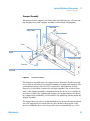
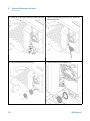
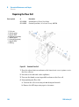
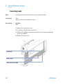
Transport Assembly
The transport unit comprises an X-axis slide (left-right motion), a Z-axis arm
(up-down motion), and a gripper assembly (rotation and vial-gripping).
I]ZiVbdidg
<g^eeZgbdidg
Mbdidg
MVm^h
<g^eeZg
Obdidgcdi^ck^Zl
OVm^h
I]ZiVVm^h
;aZmWdVgY
Figure 22
Transport Assembly
The transport assembly uses four stepper motors driven in closed-loop mode
for accurate positioning of the gripper assembly for sample-vial transport. The
rotational movement of the motors is converted to linear motion (X- and
Z-axes) by toothed belts connected to the drive spindles. The rotation (theta
axes) of the gripper assembly is transferred from the motor by a toothed belt
and series of gears. The opening and closing of the gripper fingers are driven
by a stepper motor linked by a toothed belt to the planetary gearing inside the
gripper assembly.
The stepper motor positions are determined by the optical encoders mounted
onto the stepper-motor housing. The encoders monitor the position of the
motors continually, and correct for position errors automatically (e.g. if the
1220 Infinity LC
57
3
Agilent 1220 Infinity LC Description
Injection System
gripper is accidentally moved out of position when loading vials into the vial
tray). The initialization positions of the moving components are sensed by
reflection sensors mounted on the flex board. These positions are used by the
processor to calculate the actual motor position. An additional six reflection
sensors for tray recognition are mounted on the flex board at the front of the
assembly.
Using the Autosampler
Supported trays for the autosampler
Table 22
Supported trays for the Autosampler
Description
Part Number
Tray for 100 x 2 ml vials
G1313-44510
Halftray for 15 x 6 ml vials
G1313-44513
Halftray for 40 x 2 ml vials
G1313-44512
Half-tray combinations
Half-trays can be installed in any combination enabling both 2 ml-and
6 ml-vials to be used simultaneously.
Numbering of vial positions
The standard 100-vial tray has vial positions 1 to 100. However, when using
two half-trays, the numbering convention is slightly different. The vial
positions of the right-hand half tray begin at position 101 as follows:
Left-hand 40-position tray: 1 - 40
Left-hand 15-position tray: 1–15
Right-hand 40-position tray: 101–140
Right-hand 15-position tray: 101–115
58
1220 Infinity LC
Agilent 1220 Infinity LC Description
Injection System
3
Choice of Vials and Caps
For reliable operation, vials used with the Agilent 1220 Infinity LC
autosampler must not have tapered shoulders or caps that are wider than the
body of the vial. The vials and caps shown with their part numbers in the
tables below have been successfully tested using a minimum of 15,000
injections with the Agilent 1220 Infinity LC autosampler.
Table 23
Description
Volume (ml)
100/Pack
1000/Pack
Clear glass
2
5181-3375
5183-4491
Clear glass,
write-on spot
2
5182-0543
5183-4492
5183-4494
Amber glass,
write-on spot
2
5182-3376
5183-4493
5183-4495
Polypropylene,
wide opening
1
5182-0567
Polypropylene,
wide opening
0.3
Table 24
1220 Infinity LC
Crimp Top Vials
100/Pack
(silanized)
5183-4496
9301-0978
Snap Top Vials (continued)
Description
Volume (ml)
100/Pack
1000/Pack
100/Pack
(silanized)
Clear glass
2
5182-0544
5183-4504
5183-4507
Clear glass,
write-on spot
2
5182-0546
5183-4505
5183-4508
Amber glass,
write-on spot
2
5182-0545
5183-4506
5183-4509
59
3
Agilent 1220 Infinity LC Description
Injection System
Table 25
Description
Volume (ml)
100/Pack
1000/Pack
100/Pack
(silanized)
Clear glass
2
5182-0714
5183-2067
5183-2070
Clear glass,
write-on spot
2
5182-0715
5183-2068
5183-2071
Amber glass,
write-on spot
2
5182-0716
5183-2069
5183-2072
Table 26
Crimp Caps
Description
Septa
100/Pack
Silver aluminum
Clear PTFE/red rubber
5181-1210
Silver aluminum
Clear PTFE/red rubber
5183-4498 (1000/Pack)
Blue aluminum
Clear PTFE/red rubber
5181-1215
Green aluminum
Clear PTFE/red rubber
5181-1216
Red aluminum
Clear PTFE/red rubber
5181-1217
Description
Septa
100/Pack
Clear polypropylene
Clear PTFE/red rubber
5182-0550
Blue polypropylene
Clear PTFE/red rubber
5182-3458
Green polypropylene
Clear PTFE/red rubber
5182-3457
Red polypropylene
Clear PTFE/red rubber
5182-3459
Description
Septa
100/Pack
Blue polypropylene
Clear PTFE/red rubber
5182-0717
Green polypropylene
Clear PTFE/red rubber
5182-0718
Table 27
Table 28
60
Screw Top Vials
Snap Caps
Screw Caps
1220 Infinity LC
Agilent 1220 Infinity LC Description
Injection System
Table 28
1220 Infinity LC
3
Screw Caps
Description
Septa
100/Pack
Red polypropylene
Clear PTFE/red rubber
5182-0719
Blue polypropylene
Clear PTFE/silicone
5182-0720
Green polypropylene
Clear PTFE/silicone
5182-0721
Red polypropylene
Clear PTFE/silicone
5182-0722
61
3
Agilent 1220 Infinity LC Description
Column Oven
Column Oven
The column oven is based on a resistor heater matt with two thermal sensors
to provide constant temperature in the whole column area. A build in over
temperature cut off fuse inhibits overheating.
The inner volume of the oven capillary is 6µl.
Maximum column length is 25cm (10 inch).
Operational range is 5 degree above ambient, at least 10 °C up to 60 °C, max
specified flow rate is 5ml/min at 60 °C.
NOTE
62
Never operate the column oven with open front cover, to ensure a correct column
temperature always operate with closed front cover. The counterpart of the oven isolation
is fixed at the inner side of the front cover.
1220 Infinity LC
Agilent 1220 Infinity LC Description
Detector
3
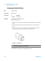
Detector
Detector
The Agilent 1220 Infinity LC variable wavelength detector is designed for
highest optical performance, GLP compliance and easy maintenance, with:
• Deuterium lamp for highest intensity and lowest detection limit over a
wavelength range of 190 to 600 nm,
• Optional flow-cell cartridges (standard: 10 mm 14 µl, high pressure: 10 mm
14 µl, micro: 3 mm 2 µl, semi-micro: 6 mm 5 µl) are available and can be
used depending on the application needs,
• Easy front access to lamp and flow cell for fast replacement, and
• Built-in holmium oxide filter for fast wavelength accuracy verification.
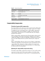
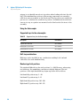
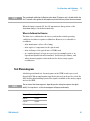
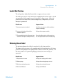
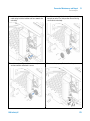
Match the Flow Cell to the Column
Figure 23 on page 64 shows recommendations for flow cells that match the
column used. If more than one selection is appropriate, use the larger flow cell
to get the best detection limit. Use the smaller flow cell for best peak
resolution.
1220 Infinity LC
63
3
Agilent 1220 Infinity LC Description
Detector
8dajbcaZc\i]
Ine^XVaeZV`
l^Yi]
12*Xb
%#%'*b^c
&%Xb
%#%*b^c
'%Xb
%#&b^c
32)%Xb
%#'b^c
Ine^XVa[adl
gViZ
>ciZgcVaXdajbcY^VbZiZg
Figure 23
GZXdbbZcYZY[adlXZaa
HZb^"b^Xgd
[adlXZaa
HiVcYVgY
[adlXZaa
%#'ba$b^c
%#'"%#)ba$b^c
%#)"%#-ba$b^c
&"*ba$b^c
&#%bb
'#&bb
(#%bb
)#+bb
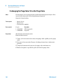
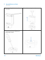
Choosing a Flow Cell
Flow Cell Path Length
Lambert-Beer’s law shows a linear relationship between the flow cell path
length and absorbance.
where
T
is the transmission, defined as the quotient of the intensity of the transmitted
light I divided by the intensity of the incident light, I0,
e
is the extinction coefficient, which is a characteristic of a given substance
under a precisely-defined set of conditions of wavelength, solvent,
temperature and other parameters,
C
is the concentration of the absorbing species (usually in g/l or mg/l), and
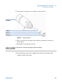
d
is the path length of the cell used for the measurement.
Therefore, flow cells with longer path lengths yield higher signals. Although
noise usually increases a little with increasing path length, there is a gain in
signal-to-noise ratio. For example, the noise increases by less than 10 %, but a
64
1220 Infinity LC
3
Agilent 1220 Infinity LC Description
Detector
70 % increase in signal intensity is achieved by increasing the path length from
6 mm to 10 mm.
When increasing the path length, the cell volume usually increases — in our
example, from 5 to 13 µl. Typically, this causes more peak dispersion. As
Figure 24 on page 65 demonstrates, this does not affect the resolution in the
gradient separation in our example.
As a rule-of-thumb, the flow cell volume should be about 1/3 of the peak
volume at half height. To determine the volume of your peaks, take the peak
width as reported in the integration results, multiply it by the flow rate and
divide it by 3.
6WhdgWVcXZ
6cVanh^hd[eZhi^X^YZhiVcYVgY
+"bbdei^XVaeVi]aZc\i]
&%"bbdei^XVaeVi]aZc\i]
I^bZb^c
Figure 24
Influence of Cell Path Length on Signal Height
Traditionally, LC analysis with UV detectors is based on comparing
measurements with internal or external standards. To check photometric
accuracy of the Agilent 1220 Infinity LC VWD, it is necessary to have more
precise information on path lengths of the VWD flow cells.
The correct response is:
expected response * correction factor
Details of the Agilent 1220 Infinity LC VWD flow cells are shown in Table 29
on page 66.
1220 Infinity LC
65
3
Agilent 1220 Infinity LC Description
Detector
Table 29
Correction factors for Agilent VWD flow cells
Flow cell type
Cell
volume
Part number
Path length
(nominal)
Path length
(actual)
Correction
factor
Standard flow cell
14 µl
G1314-60086
10 mm
10.15 ± 0.19 mm
10/10.15
Semi-micro flow cell
5 µl
G1314-60083
6 mm
6.10 ± 0.19 mm
6/6.10
Micro flow cell
2 µl
G1314-60087
3 mm
2.80 ± 0.19 mm
3/2.8
High Pressure flow cell
14 µl
G1314-60082
10 mm
10.00 ± 0.19 mm
6/5.75
NOTE
66
Be aware that there are additional tolerance of gasket thickness and its compression ratio,
which are considered to be very small in comparison with the machining tolerance.
1220 Infinity LC
1220 Infinity LC
4
Test Functions and Calibration
Agilent 1220 Infinity LC System
Installation Check 69
Module Info 70
State Info 71
69
Solvent Delivery System 72
Leak Test 71
Pressure Too High Check 72
Purge Pump 73
Autosampler 75
Maintenance Positions 75
Injector Steps 77
Alignment Teaching 78
Gripper Verification 81
Column Oven 82
Oven Test 82
Oven Calibration
83
Detector 84
Cell Test 84
Dark Current Test 85
Holmium Oxide Test 86
Intensity Test 87
Filter/Grating Motor Test
Detector Calibration 90
Test Chromatogram 91
Spectral Scan 92
89
Agilent Technologies
67
4
Test Functions and Calibration
Detector
This chapter describes the tests, calibrations and tools that are available with
the Instrument Utilities software or the Lab Advisor.
68
1220 Infinity LC
Test Functions and Calibration
Agilent 1220 Infinity LC System
4
Agilent 1220 Infinity LC System
Installation Check
The Installation Check switches on all available modules, purges the system for
five minutes at 1 mL/min, tests the flow path by applying a pressure up to 200
bar and switches on the oven (if available) and detector.
NOTE
The pump and detector are mandatory for this check; the oven and autosampler are
optional.
The installation check passes if the following conditions are met:
• All modules switch on successfully within the timeout period (120
seconds).
• The pump achieves 200 bar after 5 minutes.
• The oven reaches 2°K above its actual temperature.
• The detector lamp ignites and the detector reaches a Ready state.
1220 Infinity LC
69
4
Test Functions and Calibration
Agilent 1220 Infinity LC System
Module Info
Module Info Description
The Module Info tool collects diagnostic information from a module and writes
the resuls to a file. You can view the results in three tabs:
General
The General tab shows information about the module's firmware and options in
a two-column table.
Tables
The Tables tab allows you to display the contents of all available diagnostic
tables for the module. You click the [+] sign to open a table, or the [-] sign to
close an open table.
Signals
The Signals tab shows the plots of the available diagnostic signals from the
module. The signal plots that are available are module-dependent; where
available, both short-term and long-term plots are displayed for a signal.
Displaying Module Info
To display the information for a selected module:
1 Select Tools from the explorer pane. The Tools screen shows all available
modules for the current instrument.
2 In the Tools screen, select the module for which you want to display
information from the Module Selection pane.
3 In the Tools Selection pane, select Module Info.
4 Click Start. The module information for the selected module is displayed.
70
1220 Infinity LC
Test Functions and Calibration
Agilent 1220 Infinity LC System
4
State Info
The State Info tool displays the current status of all Agilent 1220 Infinity LC
modules; the status is continuously updated. Unless aborted, the tool runs
continuously for 60 minutes. You click Abort to stop the tool.
1220 Infinity LC
71
4
Test Functions and Calibration
Solvent Delivery System
Solvent Delivery System
Pressure Too High Check
Pressure Too High Check Description
This test checks the flow path for a blockage, and tries to identify the module
that is causing the blockage. If the blockage is in the autosampler, the test can
identify whether the blockage occurs in the needle or needle seat.
The pump and autosampler are necessary to run the Pressure Too High Check.
Pressure Too High Check Evaluation
Start Conditions
The pump and autosampler are brought to the READY state, and an operating
pressure of 200 bar is applied to the system.
The pump ripple is measured, and the start of the test is delayed until the
ripple is within the defined limits (typically 1% of operating pressure).
Test Part 1
Part 1 of the test tries to determine in which part of the system the pressure
problem lies.
After the system has achieved the start conditions, the autosampler valve is
switched from mainpass to bypass, and the pressure slice is tested against a
limit.
If the limit is exceeded, the pressure problem lies in the autosampler;
otherwise, it lies somewhere in the rest of the flow path.
Test Part 2
In Part 2 of the test, an empty vial is driven to the needle, and the valve is
switched from bypass to mainpass, so that the pressure should drop
dramatically. The pressure drop is checked against a limit.
72
1220 Infinity LC
4
Test Functions and Calibration
Solvent Delivery System
If the autosampler is identified as the source of the problem, and the limit is
not reached, the problem lies in the needle, needle loop or metering drive;
otherwise, the problem lise in the needle seat or needle seat capillary.
If the autosampler is not the source of the problem, the problem lies either in
the pump (typically the filter or frit), or after the autosampler (heater
capillary or column). If the pressure drop limit is not achieved, the problem
lies in the pump; otherwise, the problem occurs after the autosampler.
Purge Pump
Purge Pump Description
The Purge Pump tool enables you to purge the pump with solvent at a specified
flow rate for a specified time. For multi-channel pumps, and pumps with
solvent selection valve (SSV), you select the channels to purge; each channel
can be purged with different conditions.
You can select a flow rate between 1 and 5 mL/min in steps of 1 mL/min.
You can select a time from 1, 2, 3, 5, 7, 10 and 15 minutes.
NOTE
The G1361A Prep Pump has an automatic purge cycle; there are no user-configurable
options.
Purging the Pump
To purge the pump
1 Prepare each channel with the appropriate purge solvents.
2 Select Purge Pump from the tool selection screen
3 In the Purge Configuration dialog box,
If necessary, select the channel(s) that you want to purge.
For each selected channel, select a Flow and a purge Time.
Click OK to close the Purge Configuration dialog box.
4 When the request to open the purge valve appears, open the purge valve on
the pump, then click OK to close the message box.
1220 Infinity LC
73
4
Test Functions and Calibration
Solvent Delivery System
During purging, the General tab shows the current channel that is being
purged, and the remaining purge time. The Signals tab shows a plot of
pressure against time for the complete purge cycle.
5 When the purge time has elapsed and the request to close the purge valve
appears, close the purge valve on the pump, then click OK to close the
message box.
The pump purge process is complete.
74
1220 Infinity LC
Test Functions and Calibration
Autosampler
4
Autosampler
Maintenance Positions
Change Needle
The Change Needle function moves the safety flap out of position, and positions
the needle for easy exchange and alignment.
Start
moves the safety
flap away from
the needle, and
positions the
needle
approximately 15
mm above the
needle seat.
Up
moves the needle
arm up stepwise.
Down
moves the needle
arm down
stepwise. The
lowest position is
used to align the
needle at the
correct position in
the needle arm.
End
repositions the
safety flap around
the needle.
Change Piston
The Change Piston function draws the piston away from the home position,
relieving the tension on the spring. In this position, the analytical head
assembly can be removed and reinstalled easily after maintenance.
1220 Infinity LC
75
4
Test Functions and Calibration
Autosampler
Start
draws the piston
away from the
home position,
relieving the
tension on the
spring.
End
repositions the
plunger at the
home position.
Change Gripper
The Change Gripper function moves the gripper to the front of the autosampler
enabling easy access to the gripper release mechanism.
Start
moves the gripper
to the front of the
sample-tray area.
End
repositions the
gripper at the
home position.
Arm Position
76
Move Arm Home
Moves the gripper
arm to its home
position for better
access and
exchange of trays.
Park Arm
Secures the
gripper arm to the
park position
behind the
sampling unit.
Before parking
the gripper arm,
ensure there is no
vial in the gripper.
1220 Infinity LC
Test Functions and Calibration
Autosampler
4
Injector Steps
Each movement of the sampling sequence can be done under manual control.
This is useful during troubleshooting, where close observation of each of the
sampling steps is required to confirm a specific failure mode or verify
successful completion of a repair.
Each injector step command actually consists of a series of individual
commands that move the autosampler components to predefined positions,
enabling the specific step to be done.
Table 30
1220 Infinity LC
Injector Step Commands
Step
Action
Comments
Valve Bypass
Switches injection valve to the bypass
position.
Plunger Home
Moves the plunger to the home
position.
Needle Up
Lifts the needle arm to the upper
position.
Command also switches the
valve to bypass if it is not
already in that position.
Vial to Seat
Moves the selected vial to the seat
position.
Command also lifts the needle
to the upper position.
Needle into Sample
Lowers the needle into the sample.
Command also positions the
vial at the seat, and lifts the
needle to the upper position.
Draw
Metering device draws the defined
injection volume.
Command also positions the
vial at the seat, lifts the
needle, and lowers the needle
into vial. Command can be
done more than once
(maximum draw volume of
100µl cannot be exceeded).
Use Plunger Home to reset the
metering device.
Needle Up
Lifts the needle out of the vial.
Command also switches the
valve to bypass if it is not
already in that position.
77
4
Test Functions and Calibration
Autosampler
Table 30
Injector Step Commands
Step
Action
Comments
Vial to Tray
Returns the selected vial to the tray
position.
Command also lifts the needle
to the upper position.
Needle into Seat
Lowers the needle arm into the seat.
Command also returns the vial
to the tray position.
Valve Mainpass
Switches the injection valve to the
mainpass position.
Reset
Resets the injector.
Alignment Teaching
ALS Alignment Teaching Description
The Alignment Teaching tool is required to compensate for small deviations in
positioning of the autosampler gripper that may occur after the module has
been disassembled for repair. It requires that a 100-vial tray be inserted into
the autosampler.
The alignment procedure uses two tray positions as reference points; because
the tray is rectangular, a two-point alignment is sufficient to correct all other
vial positions on the tray. When the correction calculation is complete, the
values for both X and theta are rounded to one decimal place. On completion
of the alignment procedure, the corrected gripper positions are stored in the
module's firmware.
NOTE
78
To ensure correct operation of the autosampler, the alignment procedure must be carried
out in the correct sequence and in full (that is, without skipping any part).
1220 Infinity LC
Test Functions and Calibration
Autosampler
4
ALS Alignment Controls
Button
1220 Infinity LC
Description
Keyboard
Shortcut
Rotate the gripper
by increasing
theta
Cursor Up
Move the gripper
horizontally to the
left
Cursor Left
Move the gripper
horizontally to the
right
Cursor Right
Rotate the gripper
by decreasing
theta
Cursor Down
Arm Up
Lifts the gripper
arm
Page Up
Arm Down
Lowers the
gripper arm
Page Down
Open Gripper
Opens the gripper
Close Gripper
Closes the gripper
Start >>
Starts the
execution of the
procedure. Shown
only at the start.
Enter
Continue >>
Jumps to the next
step of the
procedure. Shown
only during
alignment.
Enter
Restart
Restarts the
execution of the
step.
79
4
Test Functions and Calibration
Autosampler
Running the ALS Alignment Teaching
NOTE
To ensure correct operation of the autosampler, the alignment procedure must be carried
out in the correct sequence and in full (that is, without skipping any part).
To align the ALS:
1 Insert a 100-vial tray into the autosampler.
2 Place capped vials into positions 15 and 95.
3 Press Start >>.
The gripper arm moves to a position above vial 15.
4 Answer Yesto reset the correction values to their factory defaults, or No to
leave them as they are.
5 Use Arm Down to move the fingers of the gripper as close as possible to the
top of the vial without touching.
6 Use B2; and BC; (for rotation), and BA; and C4; (for
movement left and right) to adjust the gripper posion in the horizontal
plane.
7 Use Open Gripper to open the gripper fingers.
8 Use Arm Down to move the gripper arm down a further 5 mm until the vial
cap and the rubber of the gripper fingers are the same height.
9 Check that the vial is in the center of the gripper fingers and readjust the
position if necessary (step 6).
10 When you are satisfied that the gripper position is correct, press Continue.
The gripper arm moves to a position above vial 95.
11 Repeat steps 6 to 9 to align the gripper at position 95.
12 Press Continue.
On completion of the calculation, the values for both X and theta are
rounded to one decimal place. The correction values are stored
permanently in the non-volatile memory of the sampler, and the sampler is
initialized.
80
1220 Infinity LC
4
Test Functions and Calibration
Autosampler
Gripper Verification
ALS Gripper Verification Description
The verification procedure uses several vial positions as reference points to
verify the gripper alignment is correct. If verification indicates one or more
positions are out of alignment, the alignment procedure should be done.
Verifying the Gripper Positions
Vial positions 1,10,55,81 and 100 can be used for position verification.
1 Insert empty capped vials into the vial tray at the positions to be verified.
2 Select the first vial position in the vial-position menu.
3 Select Go to selected position.
4 If the fingers of the gripper arm are aligned centrally above the vial, select
the Pick vial button to verify the gripper arm lifts the vial out of the tray
correctly. If there is a misalignment, the gripper must be realigned.
5 Select the Put vial button to verify the gripper replaces the vial correctly. If
there is a misalignment, the gripper must be realigned.
6 Repeat the procedure for the next vial position.
1220 Infinity LC
81
4
Test Functions and Calibration
Column Oven
Column Oven
Oven Test
Oven Test Description
The Oven Test is used to evaluate the heating performance of the two Peltier
elements.
The heating rate over a 10°K interval from the start temperature is
determined. The start temperature must be between 30°C and 50°C, and is
determined as follows:
• If the current oven temperature is below 30°C, the oven tries to attain a
temperature of 30°C. 30°C is used as the start temperature.
• If the current oven temperature is above 30°C but below 50°C, the current
oven temperature is used as the start temperature.
• If the current oven temperature is above 50°C, an error message is
displayed. The oven must then be allowed to cool to below 50°C before the
test can be run.
Oven Test Evaluation
At the end of the Oven Test, the slope of the temperature rise of the left and
right channels are evaluated. The test passes if both slopes are >=4°C/min.
82
1220 Infinity LC
4
Test Functions and Calibration
Column Oven
Oven Calibration
Oven Calibration Description
The oven calibration procedure enables the oven temperature to be measured
against an external, calibrated measuring device.
Normally, temperature calibration is not required during the lifetime of the
instrument; however, in order to comply with local regulatory requirements,
the 2-point calibration and verification procedure may be performed.
Running the Oven Calibration
NOTE
For the measurement and calibration procedure, we recommend a measuring device that
provides the necessary resolution and precision, for example, Hereaus Quat340 quartz
surface-temperature measurement sensor. Contact your local Agilent Technologies support
representative for ordering information.
1 Install the calibrated temperature measuring device.
2 Select the Oven Calibrationin the user interface.
3 Wait for the oven to reach the first set point (40°C).
4 Measure the temperature of the heat exchanger and enter the value in the
field.
5 Wait for the oven to reach the second set point (50°C).
6 Measure the temperature of the heat exchanger and enter the value in the
field.
7 Click OK to save the calibration values to the oven, or Cancel to abort the
calibration process.
1220 Infinity LC
83
4
Test Functions and Calibration
Detector
Detector
Cell Test
VWD Cell Test Description
The cell test compares the intensity of the deuterium lamp measured by the
sample and reference diodes (unfiltered and not logarithmized) when the
grating is in the zero-order position. The resulting intensity ratio
(sample:reference) is a measure of the amount of light absorbed by the flow
cell. The test can be used to check for dirty or contaminated flow cell
windows. When the test is started, the gain is set to -1. To eliminate effects due
to absorbing solvents, the test should be done with water in the flow cell.
NOTE
The test should not be performed using the micro flow cell, since the reduction in light
intensity will cause the test to fail.
Evaluating the VWD Cell Test Results
The intensity ratio is dependent on the degree of contamination of the flow
cell windows, and on the type of flow cell used. The lower the ratio, the more
light is absorbed by the flowcell.
Table 31
84
Probable causes of excessive flowcell absorbance
Cause
Corrective action
Absorbing solvent
or air bubble in
flow cell.
Ensure the flow
cell is filled with
water, and free
from air bubbles.
Dirty or
contaminated
flow cell.
Exchange the
flow cell
windows.
1220 Infinity LC
Test Functions and Calibration
Detector
4
Dark Current Test
VWD Dark Current Test Description
The dark-current test measures the leakage current from the sample and
reference circuits. The test is used to check for defective sample or reference
diodes or ADC circuits which may cause non-linearity or excessive baseline
noise. During the test, the lamp is switched off. Next, the leakage current from
both diodes is measured. The test evaluates the results automatically.
Evaluating the VWD Dark Current Test
Table 32
Limits
Sample circuit
<7900 counts
Reference circuit
<7900 counts
Probable causes of test failure
Table 33
Cause
Corrective action
Defective sample
diode
Exchange the
sample diode.
Defective sample
ADC board.
Exchange the
sample ADC
board.
Table 34
1220 Infinity LC
Sample circuit noise exceeds limit:
Reference circuit noise exceeds limit:
Cause
Corrective action
Defective
reference diode.
Exchange the
reference diode.
Defective
reference ADC
board.
Exchange the
reference ADC
board.
85
4
Test Functions and Calibration
Detector
Holmium Oxide Test
VWD Holmium Oxide Test Description
The holmium oxide test uses three characteristic absorbance maxima of the
built-in holmium oxide filter to verify wavelength accuracy (see also
Wavelength Calibration). The test evaluates the results automatically, and
provides a spectrum of the holmium oxide filter. To eliminate effects due to
absorbing solvents, the test should be done with water in the flow cell. On
completion of the test, the results are displayed automatically.
Holmium Oxide Test Report
86
1220 Infinity LC
Test Functions and Calibration
Detector
4
Evaluating the VWD Holmium Oxide Test
The test is evaluated by the instrument, and the measured maxima are
displayed automatically. The test fails if one or more of the maxima lies
outside the limits.
Table 35
Limits
Absorbance
Maxima
Limits
360.8 nm
-1 to +1 nm
418.5 nm
-1 to +1 nm
536.4 nm
-1 to +1 nm
Intensity Test
VWD Intensity Test Description
The intensity test measures the intensity of the UV lamp over the full VWD
wavelength range (190-800 nm). The test evaluates the results automatically,
and provides an intensity spectrum. The test evaluates the highest intensity,
average intensity, and lowest intensity across the full wavelength range. The
test is used to determine the performance of the lamp and optics (see also cell
test). To eliminate effects due to absorbing solvents, the test should be done
with water in the flow cell. The shape of the intensity spectrum is primarily
dependent on the lamp and grating. Therefore, intensity spectra will differ
slightly between instruments. On completion of the test, the intensity
spectrum and intensity values are displayed (“VWD Cell Test Description” on
page 84).
NOTE
1220 Infinity LC
The test should not be performed using the micro flow cell, since the reduction in light
intensity will cause the test to fail.
87
4
Test Functions and Calibration
Detector
Intensity Test Report
> 320000 cts
> 160000 cts
> 6400 cts
7123680 cts
951488 cts
36384 cts
Evaluating the VWD Intensity Test
Table 36
88
Limits
Intensity
Limits (counts)
Highest
>320000
Average
>160000
Lowest
>6400
1220 Infinity LC
4
Test Functions and Calibration
Detector
Table 37
Probable causes of test failure
Cause
Corrective action
Lamp off.
Switch on the
lamp.
Old lamp.
Exchange the
lamp.
Absorbing solvent
or air bubble in
flow cell.
Ensure the flow
cell is filled with
water, and free
from air bubbles.
Dirty or
contaminated
flow cell.
Run theCell Test .
If the test fails,
exchange the flow
cell windows
(“VWD Cell Test
Description” on
page 84).
Filter/Grating Motor Test
VWD Filter/Grating Test Description
The actual position of the filter motor and grating motor is defined as the
number of steps from the reference (sensor) positions. The filter/grating test
counts the number of motor steps required to move the filter motor and
grating motor back to the reference (sensor) position. If the number of steps
required to reach the reference positions are the same as the expected step
number, the test is passed. If a motor fails to move, or loses motor steps, the
test fails. The test evaluates the results automatically.
VWD Filter/Grating Test Results
Probable causes of test failure:
1220 Infinity LC
89
4
Test Functions and Calibration
Detector
Table 38
Filter Motor Test
Cause
Corrective action
Defective filter
motor assembly.
Exchange the
filter motor
assembly.
Defective VWM
board.
Exchange the
VWM board.
Table 39
Grating Motor Test
Cause
Corrective action
Defective filter
motor assembly.
Exchange the
filter motor
assembly.
Defective VWM
board.
Exchange the
VWM board.
Detector Calibration
Wavelength Verification/Calibration
Wavelength calibration of the detector is done using the zero-order position
and 656 nm (alpha-emission line) and beta-emission line at 486 nm
emission-line positions of the deuterium lamp. The calibration procedure
involves three steps. First the grating is calibrated on the zero-order position.
The stepper-motor step position where the zero-order maximum is detected is
stored in the detector. Next, the grating is calibrated against the deuterium
emission-line at 656 nm, and the motor position at which the maximum occurs
is stored in the detector. Finally, the grating is calibrated against the
deuterium emission-line at 486 nm, and the motor position at which the
maximum occurs is stored in the detector.
90
1220 Infinity LC
Test Functions and Calibration
Detector
NOTE
4
The wavelength verification/calibration takes about 2.5 minutes and is disabled within the
first 10 minutes after ignition of the lamp because initial drift may distort the measurement.
When the lamp is turned ON, the 656 nm emission line position of the
deuterium lamp is checked automatically.
When to Calibrate the Detector
The detector is calibrated at the factory, and under normal operating
conditions should not require recalibration. However, it is advisable to
recalibrate:
• after maintenance (flow cell or lamp),
• after repair of components in the optical unit,
• after exchange of the optical unit or VWM board,
• at a regular interval, at least once per year (for example, prior to an
Operational Qualification/Performance Verification procedure), and
• when chromatographic results indicate the detector may require
recalibration.
Test Chromatogram
A built-in pre-defined test chromatogram on the VWM board is processed
through ADC like normal signals from the diodes and can be used to check the
ADC and the data handling system. The signal is available at the analog output
and on the GPIB.
NOTE
1220 Infinity LC
The run time of the chromatogram is depending on the setting for response time (peak
width). If no stop time is set the chromatogram will repeat continuously.
Response Time
Stop Time
0.06 sec
0.8 min.
0.12 sec
0.8 min.
0.25 sec
0.8 min.
91
4
Test Functions and Calibration
Detector
Response Time
Stop Time
0.50 sec
0.8 min.
1.00 sec
1.6 min.
2.00 sec
3.2 min. (Default
settings)
4.00 sec
6.4 min.
8.00 sec
12.8 min.
The test chromatogram has four main peaks with the following absorbances:
Peak
Absorbance
(approx.)
1
38 mAU
2
100 mAU
3
290 mAU
4
20 mAU
Spectral Scan
The Spectral Scan tool is available for diode-array and variable wavelength
detectors (DAD/MWD and VWD). It allows you to scan a spectrum over a
specified wavelength range and export the data to a csv (comma-separated
values) file that can be used in other applications (for example, Microsoft
Excel).
92
1220 Infinity LC
Test Functions and Calibration
Detector
4
Scan Parameters
1220 Infinity LC
UV Lamp On
Switches on the UV lamp.
Blank Scan
(VWD only)
Scans a blank spectrum (solvent only) over
the specified wavelength range at the
specified resolution. You specify the
wavelength range in the from and to fields,
and the resolution in the step field.
Sample Scan
Scans the sample spectrum over the
specified wavelength range at the specified
resolution. You specify the wavelength
range in the from and to fields, and the
resolution in the step field.
Export Data
Exports the selected data in csv format.
Using the options in the Export Filter
section, you can select to export only the
peak maxima, all peak data (the peak
maximum and four adjacent values to left
and right) or all data points.
93
4
94
Test Functions and Calibration
Detector
1220 Infinity LC
1220 Infinity LC
5
Error Information
What are Error Messages?
98
General Error Messages 99
Compensation Sensor Open
Compensation Sensor Short
Fan Failed 100
Leak 101
Leak Sensor Open 101
Leak Sensor Short 102
Open Cover 102
Remote Timeout 103
Shut-Down 103
Synchronization Lost 104
Timeout 104
99
100
Pump Error Messages 105
Encoder Missing 105
Index Adjustment 105
Index Limit 106
Index Missing 106
Initialization Failed 107
Missing Pressure Reading 107
Motor-Drive Power 108
Pressure Above Upper Limit 109
Pressure Below Lower Limit 109
Pressure Signal Missing 110
Pump Configuration 110
Pump Head Missing 111
Restart Without Cover 111
Servo Restart Failed 112
Agilent Technologies
95
5
Error Information
Detector
Stroke Length 112
Temperature Limit Exceeded 113
Temperature Out of Range 113
Valve Failed 114
Valve Fuse 115
Wait Timeout 116
Zero Solvent Counter 116
Autosampler Error Messages 117
Arm Movement Failed 117
Initialization Failed 118
Initialization with Vial 118
Invalid Vial Position 119
Metering Home Failed 119
Missing Vial 120
Missing Wash Vial 120
Motor Temperature 121
Needle Down Failed 122
Needle Up Failed 123
Safety Flap Missing 123
Valve to Bypass Failed 124
Valve to Mainpass Failed 124
Vial in Gripper 125
Detector Error Messages 126
ADC Hardware Error 126
Calibration Failed 126
Filter Check Failed 127
Filter Missing 127
Grating/Filter Motor Test Failed 128
Grating Missing 128
Heater Current Missing 129
Heater Failed 129
Heater Power At Limit 130
Holmium Oxide Test Failed 130
Illegal Value From Air Inlet Temperature Sensor
Illegal Value From Temperature Sensor 131
96
131
1220 Infinity LC
Error Information
Detector
5
Lamp Current Missing 132
Lamp Ignition Failed 132
Lamp Voltage Missing 133
Wavelength Check Failed 133
This chapter provides information on the error messages that might be
displayed, and gives the possible causes and suggestions on their solutions.
1220 Infinity LC
97
5
Error Information
What are Error Messages?
What are Error Messages?
Error messages are displayed in the user interface when an electronic,
mechanical, or hydraulic (flow path) failure occurs which requires attention
before the analysis can be continued (for example, repair, or exchange of
consumables is necessary). In the event of such a failure, the red status
indicator at the front of the module is switched on, and an entry is written
into the module logbook.
98
1220 Infinity LC
Error Information
General Error Messages
5
General Error Messages
General error messages are generic to all Agilent series HPLC modules and
may show up on other modules as well.
Compensation Sensor Open
The ambient-compensation sensor (NTC) on the main board in the module has
failed (open circuit).
The resistance across the temperature compensation sensor (NTC) on the
main board is dependent on ambient temperature. The change in resistance is
used by the leak circuit to compensate for ambient temperature changes. If the
resistance across the sensor increases above the upper limit, the error
message is generated.
1220 Infinity LC
Probable cause
Suggested actions
1 Defective main board.
Please contact your Agilent service
representative.
99
5
Error Information
General Error Messages
Compensation Sensor Short
The ambient-compensation sensor (NTC) on the main board in the module has
failed (short circuit).
The resistance across the temperature compensation sensor (NTC) on the
main board is dependent on ambient temperature. The change in resistance is
used by the leak circuit to compensate for ambient temperature changes. If the
resistance across the sensor falls below the lower limit, the error message is
generated.
Probable cause
Suggested actions
1 Defective main board.
Please contact your Agilent service
representative.
Fan Failed
The cooling fan in the module has failed.
The hall sensor on the fan shaft is used by the main board to monitor the fan
speed. If the fan speed falls below a certain limit for a certain length of time,
the error message is generated.
100
Probable cause
Suggested actions
1 Fan cable disconnected.
Please contact your Agilent service
representative.
2 Defective fan.
Please contact your Agilent service
representative.
3 Defective main board.
Please contact your Agilent service
representative.
1220 Infinity LC
Error Information
General Error Messages
5
Leak
A leak was detected in the module.
The signals from the two temperature sensors (leak sensor and
board-mounted temperature-compensation sensor) are used by the leak
algorithm to determine whether a leak is present. When a leak occurs, the leak
sensor is cooled by the solvent. This changes the resistance of the leak sensor
which is sensed by the leak-sensor circuit on the main board.
Probable cause
Suggested actions
1 Loose fittings.
Ensure all fittings are tight.
2 Broken capillary.
Exchange defective capillaries.
Leak Sensor Open
The leak sensor in the module has failed (open circuit).
The current through the leak sensor is dependent on temperature. A leak is
detected when solvent cools the leak sensor, causing the leak-sensor current to
change within defined limits. If the current falls outside the lower limit, the
error message is generated.
Probable cause
Suggested actions
1 Leak sensor not connected to the main
Please contact your Agilent service
representative.
board.
2 Defective leak sensor.
Please contact your Agilent service
representative.
3 Leak sensor incorrectly routed, being
Please contact your Agilent service
representative.
pinched by a metal component.
1220 Infinity LC
101
5
Error Information
General Error Messages
Leak Sensor Short
The leak sensor in the module has failed (short circuit).
The current through the leak sensor is dependent on temperature. A leak is
detected when solvent cools the leak sensor, causing the leak-sensor current to
change within defined limits. If the current increases above the upper limit,
the error message is generated.
Probable cause
Suggested actions
1 Defective flow sensor.
Please contact your Agilent service
representative.
2 Leak sensor incorrectly routed, being
Please contact your Agilent service
representative.
pinched by a metal component.
Open Cover
The top foam has been removed.
102
Probable cause
Suggested actions
1 Foam not activating the sensor.
Please contact your Agilent service
representative.
2 Dirty or defective sensor.
Please contact your Agilent service
representative.
1220 Infinity LC
5
Error Information
General Error Messages
Remote Timeout
A not-ready condition is still present on the remote input. When an analysis is
started, the system expects all not-ready conditions (for example, a not-ready
condition during detector balance) to switch to run conditions within one
minute of starting the analysis. If a not-ready condition is still present on the
remote line after one minute the error message is generated.
Probable cause
Suggested actions
1 Not-ready condition in one of the
Ensure the instrument showing the not-ready
condition is installed correctly, and is set up
correctly for analysis.
instruments connected to the remote line.
2 Defective remote cable.
Exchange the remote cable.
3 Defective components in the instrument
Check the instrument for defects (refer to the
instrument’s documentation).
showing the not-ready condition.
Shut-Down
An external instrument has generated a shut-down signal on the remote line.
The module continually monitors the remote input connectors for status
signals. A LOW signal input on pin 4 of the remote connector generates the
error message.
Probable cause
Suggested actions
1 Leak detected in another module with a CAN Fix the leak in the external instrument before
connection to the system.
restarting the module.
2 Leak detected in an external instrument with Fix the leak in the external instrument before
a remote connection to the system.
3 Shut-down in an external instrument with a
remote connection to the system.
1220 Infinity LC
restarting the module.
Check external instruments for a shut-down
condition.
103
5
Error Information
General Error Messages
Synchronization Lost
During an analysis, the internal synchronization or communication between
one or more of the modules in the system has failed.
The system processors continually monitor the system configuration. If one or
more of the modules is no longer recognized as being connected to the system,
the error message is generated.
Probable cause
Suggested actions
1 CAN cable disconnected.
•
Ensure all the CAN cables are connected
correctly.
•
Ensure all CAN cables are installed correctly.
2 Defective CAN cable.
Exchange the CAN cable.
3 Defective main board in another module.
Switch off the system. Restart the system, and
determine which module or modules are not
recognized by the system.
Timeout
The timeout threshold was exceeded.
Probable cause
Suggested actions
1 The analysis was completed successfully,
Check the logbook for the occurrence and
source of a not-ready condition. Restart the
analysis where required.
and the timeout function switched off the
module as requested.
2 A not-ready condition was present during a
sequence or multiple-injection run for a
period longer than the timeout threshold.
104
Check the logbook for the occurrence and
source of a not-ready condition. Restart the
analysis where required.
1220 Infinity LC
5
Error Information
Pump Error Messages
Pump Error Messages
These errors are specific to the pump.
Encoder Missing
The optical encoder on the pump motor in the module is missing or defective.
The processor checks the presence of the pump encoder connector every
2 seconds. If the connector is not detected by the processor, the error message
is generated.
Probable cause
Suggested actions
1 Defective or disconnected pump encoder
Ensure the connector is clean, and seated
correctly.
connector.
2 Defective pump drive assembly.
Exchange the pump drive assembly.
Index Adjustment
The encoder index position in the module is out of adjustment.
During initialization, the first plunger is moved to the mechanical stop. After
reaching the mechanical stop, the plunger reverses direction until the encoder
index position is reached. If the time to reach the index position is too long,
the error message is generated.
1220 Infinity LC
Probable cause
Suggested actions
1 Irregular or sticking drive movement.
Remove the pump head, and examine the seals,
plungers, and internal components for signs of
wear, contamination or damage. Exchange
components as required.
2 Defective pump drive assembly.
Exchange the pump drive assembly.
105
5
Error Information
Pump Error Messages
Index Limit
The time required by the plunger to reach the encoder index position was too
short (pump).
During initialization, the first plunger is moved to the mechanical stop. After
reaching the mechanical stop, the plunger reverses direction until the encoder
index position is reached. If the index position is reached too fast, the error
message is generated.
Probable cause
Suggested actions
1 Irregular or sticking drive movement.
Remove the pump head, and examine the seals,
plungers, and internal components for signs of
wear, contamination or damage. Exchange
components as required.
2 Defective pump drive assembly.
Exchange the pump drive assembly.
Index Missing
The encoder index position in the module was not found during initialization.
During initialization, the first plunger is moved to the mechanical stop. After
reaching the mechanical stop, the plunger reverses direction until the encoder
index position is reached. If the index position is not recognized within a
defined time, the error message is generated.
106
Probable cause
Suggested actions
1 Disconnected or defective encoder cable.
Ensure the encoder cable are not damaged or
dirty. Make sure the cables are connected
securely to the main board.
2 Defective pump drive assembly.
Exchange the pump drive assembly.
1220 Infinity LC
5
Error Information
Pump Error Messages
Initialization Failed
The module failed to initialize successfully within the maximum time window.
A maximum time is assigned for the complete pump-initialization cycle. If the
time is exceeded before initialization is complete, the error message is
generated.
Probable cause
Suggested actions
1 Blocked passive inlet valve.
Exchange the inlet valve.
2 Defective pump drive assembly.
Exchange the pump drive assembly.
3 Defective main board.
Exchange the main board.
Missing Pressure Reading
The pressure readings read by the pump ADC (analog-digital converter) are
missing.
The ADC reads the pressure readings from the damper every 1ms. If the
readings are missing for longer than 10 seconds, the error message is
generated.
1220 Infinity LC
Probable cause
Suggested actions
1 Damper disconnected.
Ensure the damper is connected, clean and
seated correctly.
2 Defective damper.
Exchange the damper.
3 Defective main board.
Exchange the main board.
107
5
Error Information
Pump Error Messages
Motor-Drive Power
The current drawn by the pump motor exceeded the maximum limit.
Blockages in the flow path are usually detected by the pressure sensor in the
damper, which result in the pump switching off when the upper pressure limit
is exceeded. If a blockage occurs before the damper, the pressure increase
cannot be detected by the pressure sensor and the module will continue to
pump. As pressure increases, the pump drive draws more current. When the
current reaches the maximum limit, the module is switched off, and the error
message is generated.
Probable cause
Suggested actions
1 Flow path blockage in front of the damper.
Ensure the capillaries and frits between the
pump head and damper inlet are free from
blockage.
2 Blocked outlet ball valve.
Exchange the outlet ball valve.
3 High friction (partial mechanical blockage) in Remove the pump-head assembly. Ensure there
the pump drive assembly.
108
is no mechanical blockage of the pump-head
assembly or pump drive assembly.
4 Defective pump drive assembly.
Exchange the pump drive assembly.
5 Defective main board.
Exchange the main board.
1220 Infinity LC
5
Error Information
Pump Error Messages
Pressure Above Upper Limit
The system pressure has exceeded the upper pressure limit.
Probable cause
Suggested actions
1 Upper pressure limit set too low.
Ensure the upper pressure limit is set to a value
suitable for the analysis.
2 Blockage in the flowpath (after the damper). Check for blockage in the flowpath. The
following components are particularly subject to
blockage: purge-valve frit, needle (autosampler),
seat capillary (autosampler), sample loop
(autosampler), column frits and capillaries with
low internal diameters (e.g. 0.12 mm id).
3 Defective damper.
Exchange the damper.
4 Defective main board.
Exchange the main board.
Pressure Below Lower Limit
The system pressure has fallen below the lower pressure limit.
Probable cause
Suggested actions
1 Lower pressure limit set too high.
Ensure the lower pressure limit is set to a value
suitable for the analysis.
2 Leak.
•
Inspect the pump head, capillaries and
fittings for signs of a leak.
•
Purge the module. Run a pressure test to
determine whether the seals or other
module components are defective.
3 Defective main board.
1220 Infinity LC
Exchange the main board.
109
5
Error Information
Pump Error Messages
Pressure Signal Missing
The pressure signal from the damper is missing.
The pressure signal from the damper must be within a specific voltage range.
If the pressure signal is missing, the processor detects a voltage of
approximately -120mV across the damper connector.
Probable cause
Suggested actions
1 Damper disconnected.
Ensure the damper is connected correctly to the
main board.
2 Defective damper.
Exchange the damper.
Pump Configuration
At switch-on, the gradient pump has recognized a new pump configuration.
The gradient pump is assigned its configuration at the factory. If the gradient
valve is disconnected, and the gradient pump is rebooted, the error message is
generated. However, the pump will function as an isocratic pump in this
configuration.The error message reappears after each switch-on.
110
Probable cause
Suggested actions
1 Gradient valve disconnected.
Reconnect the gradient valve.
1220 Infinity LC
5
Error Information
Pump Error Messages
Pump Head Missing
The pump-head end stop in the pump was not found.
When the pump restarts, the metering drive moves forward to the mechanical
end stop. Normally, the end stop is reached within 20 seconds, indicated by an
increase in motor current. If the end point is not found within 20 seconds, the
error message is generated.
Probable cause
Suggested actions
1 Pump head not installed correctly (screws
Install the pump head correctly. Ensure nothing
(e.g. capillary) is trapped between the pump
head and body.
not secured, or pump head not seated
correctly).
2 Broken plunger.
Exchange the plunger.
Restart Without Cover
The module was restarted with the top cover and foam open.
The sensor on the main board detects when the top foam is in place. If the
module is restarted with the foam removed, the module switches off within
30 s, and the error message is generated.
Probable cause
Suggested actions
1 The module started with the top cover and
Reinstall the top cover and foam.
foam removed.
1220 Infinity LC
111
5
Error Information
Pump Error Messages
Servo Restart Failed
The pump motor in the module was unable to move into the correct position
for restarting.
When the module is switched on, the first step is to switch on the C phase of
the variable reluctance motor. The rotor should move to one of the C positions.
The C position is required for the servo to be able to take control of the phase
sequencing with the commutator. If the rotor is unable to move, or if the C
position cannot be reached, the error message is generated.
Probable cause
Suggested actions
1 Disconnected or defective cable.
Ensure the pump-assembly cables are not
damaged or dirty. Make sure the cables are
connected securely to the main board.
2 Mechanical blockage of the module.
Remove the pump-head assembly. Ensure there
is no mechanical blockage of the pump-head
assembly or pump drive assembly.
3 Defective pump drive assembly.
Exchange the pump drive assembly.
4 Defective main board.
Exchange the main board.
Stroke Length
The distance between the lower plunger position and the upper mechanical
stop is out of limits (pump).
During initialization, the module monitors the drive current. If the plunger
reaches the upper mechanical stop position before expected, the motor
current increases as the module attempts to drive the plunger beyond the
mechanical stop. This current increase causes the error message to be
generated.
112
Probable cause
Suggested actions
1 Defective pump drive assembly.
Exchange the pump drive assembly.
1220 Infinity LC
5
Error Information
Pump Error Messages
Temperature Limit Exceeded
The temperature of one of the motor-drive circuits is too high.
The processor continually monitors the temperature of the drive circuits on
the main board. If excessive current is being drawn for long periods, the
temperature of the circuits increases. If the temperature exceeds the upper
limit, the error message is generated.
Probable cause
Suggested actions
1 High friction (partial mechanical blockage) in Ensure the capillaries and frits between the
the pump drive assembly.
2 Partial blockage of the flowpath in front of
pump head and damper inlet are free from
blockage.
Ensure the outlet valve is not blocked.
the damper.
3 Defective pump drive assembly.
4 Defective main board.
•
Remove the pump head assembly. Ensure
there is no mechanical blockage of the pump
head assembly or pump drive assembly.
•
Exchange the pump drive assembly.
Exchange the main board.
Temperature Out of Range
The temperature sensor readings in the motor-drive circuit are out of range.
The values supplied to the ADC by the hybrid sensors must be between 0.5 V
and 4.3 V. If the values are outside this range, the error message is generated.
1220 Infinity LC
Probable cause
Suggested actions
1 Defective main board.
Exchange the main board.
113
5
Error Information
Pump Error Messages
Valve Failed
Valve 0 Failed: valve A
Valve 1 Failed: valve B
Valve 2 Failed: valve C
Valve 3 Failed:valve D
One of the valves of the multi-channel gradient valve has failed to switch
correctly.
The processor monitors the valve voltage before and after each switching
cycle. If the voltages are outside expected limits, the error message is
generated.
Probable cause
Suggested actions
1 Gradient valve disconnected.
Ensure the gradient valve is connected correctly.
2 Connection cable (inside instrument) not
Ensure the connection cable is connected
correctly.
connected.
3 Connection cable (inside instrument)
Exchange the connection cable.
defective.
4 Gradient valve defective.
114
Exchange the gradient valve.
1220 Infinity LC
5
Error Information
Pump Error Messages
Valve Fuse
Valve Fuse 0: Channels A and B
Valve Fuse 1: Channels C and D
The gradient valve in the quaternary pump has drawn excessive current
causing the electronic fuse to open.
Probable cause
Suggested actions
1 Defective gradient valve.
Restart the quaternary pump. If the error
message appears again, exchange the gradient
valve.
2 Defective connection cable (front panel to
Exchange the connection cable.
main board).
3 Defective main board.
1220 Infinity LC
Exchange the LPM board.
115
5
Error Information
Pump Error Messages
Wait Timeout
When running certain tests in the diagnostics mode or other special
applications, the pump must wait for the plungers to reach a specific position,
or must wait for a certain pressure or flow to be reached. Each action or state
must be completed within the timeout period, otherwise the error message is
generated.
Possible Reasons for a Wait Timeout:
· Pressure not reached.
· Pump channel A did not reach the delivery phase.
· Pump channel B did not reach the delivery phase.
· Pump channel A did not reach the take-in phase.
· Pump channel B did not reach the take-in phase.
· Solvent volume not delivered within the specified time.
Probable cause
Suggested actions
1 Flow changed after starting test.
Ensure correct operating condition for the
special application in use.
2 Defective pump drive assembly.
Exchange the defective pump drive assembly.
Zero Solvent Counter
Pump firmware version A.02.32 and higher allow to set solvent bottle fillings
in the data system. If the volume level in the bottle falls below the specified
value the error message appears when the feature is configured accordingly.
116
Probable cause
Suggested actions
1 Volume in bottle below specified volume.
Refill bottles and reset solvent counters.
2 Incorrect setting of limit.
Make sure the limits are set correctly.
1220 Infinity LC
5
Error Information
Autosampler Error Messages
Autosampler Error Messages
These errors are specific to the autosampler.
Arm Movement Failed
The transport assembly was unable to complete a movement in one of the
axes.
The processor defines a certain time window for the successful completion of
a movement in any particular axis. The movement and position of the
transport assembly is monitored by the encoders on the stepper motors. If the
processor does not receive the correct position information from the encoders
within the time window, the error message is generated.
See figure Figure 22 on page 57 for axes identification.
• Arm Movement 0 Failed: X-axis.
Arm Movement 1 Failed: Z-axis.
Arm Movement 2 Failed: Theta (gripper rotation).
Arm Movement 3 Failed: Gripper (gripper fingers open/close).
Probable cause
Suggested actions
1 Mechanical obstruction.
Ensure unobstructed movement of the transport
assembly.
2 High friction in the transport assembly.
Exchange the sample transport assembly.
3 Defective motor assembly.
Exchange the sample transport assembly.
4 Defective sample transport assembly flex
Exchange the sample transport assembly.
board.
5 Defective main board.
1220 Infinity LC
Exchange the main board.
117
5
Error Information
Autosampler Error Messages
Initialization Failed
The autosampler failed to complete initialization correctly.
The autosampler initialization procedure moves the needle arm and transport
assembly to their home positions in a predefined sequence. During
initialization, the processor monitors the position sensors and motor encoders
to check for correct movement. If one or more of the movements is not
successful, or is not detected, the error message is generated.
Probable cause
Suggested actions
1 Mechanical obstruction.
Ensure unobstructed movement of the transport
assembly.
2 Defective sampling unit flex board.
Exchange the transport assembly.
3 Defective transport assembly flex board.
Exchange the transport assembly.
4 Defective sampling unit motor.
Exchange the defective sampling unit motor.
5 Defective ASM board.
Exchange the ASM board.
Initialization with Vial
The autosampler attempted to initialize with a vial still in the gripper.
During initialization, the autosampler checks correct operation of the gripper
by closing and opening the gripper fingers while monitoring the motor
encoder. If a vial is still in the gripper when initialization is started, the
gripper fingers cannot close causing the error message to be generated.
118
Probable cause
Suggested actions
1 Vial still in gripper.
Remove the vial using the Release Vial function
in the user interface. Reinitialize the
autosampler.
1220 Infinity LC
5
Error Information
Autosampler Error Messages
Invalid Vial Position
The vial position defined in the method or sequence does not exist.
The reflection sensors on the transport assembly flex board are used to check
automatically which sample trays are installed (coding on tray). If the vial
position does not exist in the current sample tray configuration, the error
message is generated.
Probable cause
Suggested actions
1 Incorrect tray or trays installed.
Install the correct trays, or edit the method or
sequence accordingly.
2 Incorrect vial positions defined in the
Exchange the transport assembly.
method or sequence.
3 Tray recognition defective (dirty sample tray
or defective transport assembly flex board).
Ensure the coding surfaces of the sample tray
are clean (located at the rear of the sample tray).
Metering Home Failed
The metering plunger has failed to move back to the home position.
The home position sensor on the sampling unit flex board monitors the home
position of the plunger. If the plunger fails to move to the home position, or if
the sensor fails to recognize the plunger position, the error message is
generated.
1220 Infinity LC
Probable cause
Suggested actions
1 Dirty or defective sensor.
Exchange the sampling unit flex board.
2 Broken plunger.
Exchange the metering plunger and seal.
3 Defective metering-drive motor.
Exchange the metering-drive motor.
4 Defective ASM board.
Exchange the ASM board.
119
5
Error Information
Autosampler Error Messages
Missing Vial
No vial was found in the position defined in the method or sequence.
When the gripper arm picks a vial out of the sample tray, the processor
monitors the gripper motor encoder. If a vial is present, the closing of the
gripper fingers is limited by the vial. However, if no vial is present, the gripper
fingers close too far. This is sensed by the processor (encoder position),
causing the error message to be generated.
Probable cause
Suggested actions
1 No vial in the position defined in the method
Install the sample vial in the correct position, or
edit the method or sequence accordingly.
or sequence.
2 Incorrect gripper alignment.
Align gripper.
3 Defective gripper assembly (defective
Exchange the gripper assembly.
gripper fingers or belt).
4 Defective transport assembly flex board.
Exchange the transport assembly.
Missing Wash Vial
The wash vial programmed in the method was not found.
When the gripper arm picks a vial out of the sample tray, the processor
monitors the gripper motor encoder. If a vial is present, the closing of the
gripper fingers is limited by the vial. However, if no vial is present, the gripper
fingers close too far. This is sensed by the processor (encoder position),
causing the error message to be generated.
Probable cause
Suggested actions
1 No wash vial in the position defined in the
Install the wash vial in the correct position, or
edit the method accordingly.
method.
120
1220 Infinity LC
5
Error Information
Autosampler Error Messages
Motor Temperature
One of the motors of the transport assembly has drawn excessive current,
causing the motor to become too hot. The processor has switched OFF the
motor to prevent damage to the motor.
See figure Figure 22 on page 57 for motor identification.
• Motor 0 temperature: X-axis motor.
Motor 1 temperature: Z-axis motor.
Motor 2 temperature: Theta (gripper rotation) motor.
Motor 3 temperature: Gripper motor (motor for gripper fingers).
The processor monitors the current drawn by each motor and the time the
motor is drawing current. The current drawn by the motors is dependent on
the load on each motor (friction, mass of components etc.). If the current
drawn is too high, or the time the motor draws current is too long, the error
message is generated.
1220 Infinity LC
Probable cause
Suggested actions
1 Mechanical obstruction.
Ensure unobstructed movement of the transport
assembly.
2 High friction in the transport assembly.
Exchange the transport assembly.
3 Motor belt tension too high.
Switch OFF the autosampler at the power
switch. Wait at least 10 minutes before
switching on again.
4 Defective motor.
Exchange the transport assembly.
5 Defective transport assembly flex board.
Exchange the transport assembly.
121
5
Error Information
Autosampler Error Messages
Needle Down Failed
The needle arm failed to move down into the needle seat.
The lower position of the needle arm is monitored by a position sensor on the
sampling unit flex board. The sensor detects the successful completion of the
needle movement to the needle seat position. If the needle fails to reach the
end point, or if the sensor fails to recognize the needle arm movement, the
error message is generated.
Probable cause
Suggested actions
1 Needle installed incorrectly, or wrong needle Ensure the correct needle type is used, and
type (too long).
122
installed correctly.
2 Defective or dirty position sensor.
Exchange the sampling unit flex board.
3 Defective motor.
Exchange the needle drive motor.
4 Sticking spindle assembly.
Exchange the spindle assembly or sampling unit
assembly.
5 Defective ASM board.
Exchange the ASM board.
1220 Infinity LC
5
Error Information
Autosampler Error Messages
Needle Up Failed
The needle arm failed to move successfully from the seat or out of the vial to
the upper position.
The upper position of the needle arm is monitored by a position sensor on the
sampling unit flex board. The sensor detects the successful completion of the
needle movement to the upper position. If the needle fails to reach the end
point, or if the sensor fails to recognize the needle arm movement, the error
message is generated.
Probable cause
Suggested actions
1 Defective or dirty position sensor.
Exchange the sampling unit flex board.
2 Defective motor.
Exchange the needle drive motor.
3 Sticking spindle assembly.
Exchange the spindle assembly or sampling unit
assembly.
4 Defective ASM board.
Exchange ASM board.
Safety Flap Missing
The safety flap was not detected.
Before the needle moves down into the needle seat to inject sample, the safety
flap locks into position. Next, and the gripper checks the safety flap by trying
to move the safety flap away from the needle. If the gripper is able to move
beyond the safety flap position (safety flap not in position), the error message
is generated.
1220 Infinity LC
Probable cause
Suggested actions
1 Safety flap missing or broken.
Exchange the safety flap.
123
5
Error Information
Autosampler Error Messages
Valve to Bypass Failed
The injection valve failed to switch to the bypass position.
The switching of the injection valve is monitored by two microswitches on the
valve assembly. The switches detect the successful completion of the valve
movement. If the valve fails to reach the bypass position, or if the microswitch
does not close, the error message is generated.
Probable cause
Suggested actions
1 Defective injection valve.
Exchange the injection valve.
2 Defective ASM board.
Exchange the ASM board.
Valve to Mainpass Failed
The injection valve failed to switch to the mainpass position.
The switching of the injection valve is monitored by two microswitches on the
valve assembly. The switches detect the successful completion of the valve
movement. If the valve fails to reach the mainpass position, or if the
microswitch does not close, the error message is generated.
124
Probable cause
Suggested actions
1 Defective injection valve.
Exchange the injection valve.
2 Defective ASM board.
Exchange the ASM board.
1220 Infinity LC
5
Error Information
Autosampler Error Messages
Vial in Gripper
The gripper arm attempted to move with a vial still in the gripper.
During specific stages of the sampling sequence, no vial should be held by the
gripper. The autosampler checks if a sample vial is stuck in the gripper by
closing and opening the gripper fingers while monitoring the motor encoder. If
the gripper fingers are unable to close, the error message is generated.
1220 Infinity LC
Probable cause
Suggested actions
1 Vial still in gripper.
Remove the vial using the Release Vial function
in the user interface. Reinitialize the
autosampler.
125
5
Error Information
Detector Error Messages
Detector Error Messages
These errors are specific to the variable wavelength detector.
ADC Hardware Error
A/D-Converter hardware is defective.
Probable cause
Suggested actions
1 A/D-Converter hardware is defective.
Replace the optical unit.
Calibration Failed
The intensity maximum was not found during wavelength
calibration.Calibration 0 Failed: Zero-order calibration failed.Calibration 1
Failed: 656 nm calibration failed. During zero-order and 656 nm calibration,
the detector searches for the intensity maximum. If the maximum is not
detected within the scan range, the error message is generated.
126
Probable cause
Suggested actions
1 Lamp is OFF.
Switch on the lamp.
2 Incorrect flow cell installation.
Ensure the flow cell are installed correctly.
3 Flow cell contamination or air bubbles.
Clean/replace flow cell windows or remove air
bubbles.
4 Intensity too low.
Replace lamp.
5 Current step value too far from maximum.
Enter a different calibration step value (different
scan range). Repeat the calibration.
1220 Infinity LC
Error Information
Detector Error Messages
Probable cause
Suggested actions
6 Misaligned/defective grating assembly.
Run the grating-motor test to determine if the
grating assembly is defective. If defective,
replace the optical unit.
7 ProbableCause?
Exchange the VWM board.
5
Filter Check Failed
The automatic filter check after lamp ignition has failed. When the lamp is
switched on, the detector moves the cutoff filter into the light path. If the filter
is functioning correctly, a decrease in lamp intensity is seen. If the expected
intensity decrease is not detected, the error message is generated.
Probable cause
Suggested actions
1 Filter motor defective.
Run the filter motor test to determine if the
motor is defective.
2 Defective or missing filter.
Exchange the filter assembly.
Filter Missing
The filter motor is not detected.
1220 Infinity LC
Probable cause
Suggested actions
1 Filter motor is not connected.
Re-connect the filter motor on the main board.
2 Cable/connector defective.
Replace the optical unit or main board.
127
5
Error Information
Detector Error Messages
Grating/Filter Motor Test Failed
The motor test has failed.
test
• Test 0 Failed: Filter motor.
• Test 1 Failed: Grating motor.
During the motor tests, the detector moves the motor to the end position while
monitoring the end-position sensor. If the end position is not found, the error
message is generated.
Probable cause
Suggested actions
1 Defective motor assembly.
Please contact your Agilent service
representative.
Grating Missing
The grating motor is not detected.
128
Probable cause
Suggested actions
1 Grating motor is not connected.
Re-connect the filter motor on the main board.
2 Cable/connector defective.
Replace the optical unit or main board.
1220 Infinity LC
5
Error Information
Detector Error Messages
Heater Current Missing
The lamp heater current in the detector is missing. During lamp ignition, the
processor monitors the heater current. If the current does not rise above the
lower limit within one second, the error message is generated.
Probable cause
Suggested actions
1 Lamp disconnected.
Ensure the lamp is connected.
2 Ignition started without the top foam in
Replace the top foam, and turn on the lamp.
place.
3 Defective VWM board
Please contact your Agilent service
representative.
4 Defective or non-Agilent lamp.
Exchange the lamp.
5 Defective power supply.
Please contact your Agilent service
representative.
Heater Failed
Every time the deuterium lamp or the tungsten lamp is switched on or off a
heater self-test is performed. If the test fails an error event is created. As a
result the temperature control is switched off.
1220 Infinity LC
Probable cause
Suggested actions
1 Defective connector or cable.
Please contact your Agilent service
representative.
2 Defective heater.
Please contact your Agilent service
representative.
129
5
Error Information
Detector Error Messages
Heater Power At Limit
The available power of the heater reached either the upper or lower limit. This
event is sent only once per run. The parameter determines which limit has
been hit:
0 means upper power limit hit (excessive ambient temperature drop).
1 means lower power limit hit (excessive ambient temperature increase).
Probable cause
Suggested actions
1 Ambient conditions have changed too much
•
during the run, so that optimum results may
not be guaranteed.
Verify that the reproducibility of your results
is not affected.
•
Expose the detector to more stable ambient
conditions.
Holmium Oxide Test Failed
The holmium oxide test in the detector has failed. During the holmium test,
the detector moves the holmium filter into the light path, and compares the
measured absorbance maxima of the holmium oxide filter with expected
maxima. If the measured maxima are outside the limits, the error message is
generated.
130
Probable cause
Suggested actions
1 Misaligned/defective grating assembly.
•
Ensure the flow cell is inserted correctly, and
is free from contamination (cell windows,
buffers, and so on).
•
Run the filter-motor test to determine if the
grating motor assembly is defective.
Exchange the filter motor assembly.
•
Run the grating-motor test to determine if
the grating assembly is defective. If
defective, replace the optical unit.
1220 Infinity LC
5
Error Information
Detector Error Messages
Illegal Value From Air Inlet Temperature Sensor
This temperature sensor (located on the detector main board) delivered a
value outside the allowed range. The parameter of this event equals the
measured temperature in 1/100 centigrade. As a result the temperature
control is switched off.
Probable cause
Suggested actions
1 The temperature sensor is defect.
Please contact your Agilent service
representative.
2 Detector is exposed to illegal ambient
Verify that the ambient conditions are within the
allowed range.
conditions.
Illegal Value From Temperature Sensor
This temperature sensor delivered a value outside the allowed range. The
parameter of this event equals the measured temperature in 1/100 centigrade.
As a result the temperature control is switched off.
Probable cause
Suggested actions
1 Dirty or defective sensor.
Please contact your Agilent service
representative. Links:
2 Detector is exposed to illegal ambient
Verify that the ambient conditions are within the
allowed range.
conditions.
1220 Infinity LC
131
5
Error Information
Detector Error Messages
Lamp Current Missing
The lamp anode current is missing. The processor continually monitors the
anode current drawn by the lamp during operation. If the anode current falls
below the lower current limit, the error message is generated.
Probable cause
Suggested actions
1 Lamp disconnected.
Ensure the lamp connector is seated firmly.
2 Top foam removed while lamp is on.
Replace the top foam, and turn ON the lamp.
3 Defective or non-Agilent lamp.
Exchange the lamp.
4 Defective VWM board
Please contact your Agilent service
representative.
5 Defective power supply.
Please contact your Agilent service
representative.
Lamp Ignition Failed
The lamp failed to ignite. The processor monitors the lamp current during the
ignition cycle. If the lamp current does not rise above the lower limit within
2 – 5 seconds, the error message is generated.
132
Probable cause
Suggested actions
1 Lamp disconnected.
Ensure the lamp is connected.
2 Defective or non-Agilent lamp.
Exchange the lamp.
3 Defective power supply.
Please contact your Agilent service
representative.
4 Defective VWM board
Please contact your Agilent service
representative.
1220 Infinity LC
Error Information
Detector Error Messages
5
Lamp Voltage Missing
The lamp anode voltage is missing. The processor continually monitors the
anode voltage across the lamp during operation. If the anode voltage falls
below the lower limit, the error message is generated.
Probable cause
Suggested actions
1 Defective or non-Agilent lamp.
Exchange the lamp.
2 Defective power supply.
Please contact your Agilent service
representative.
3 Defective VWM board
Please contact your Agilent service
representative.
Wavelength Check Failed
The automatic wavelength check after lamp ignition has failed. When the lamp
is switched on, the detector waits 1 minute to warm-up the lamp. Then a check
of the deuterium emission line (656 nm) via the reference diode is performed.
If the emission line is more than 3 nm away from 656 nm, the error message is
generated.
1220 Infinity LC
Probable cause
Suggested actions
1 Calibration incorrect.
Recalibrate the detector.
133
5
134
Error Information
Detector Error Messages
1220 Infinity LC
1220 Infinity LC
6
Preventive Maintenance and Repair
PM Scope of Work and Checklist
137
Early Maintenance Feedback 138
EMF counters for the pump 138
EMF counters for the autosampler 139
EMF counters for the variable wavelength detector
139
Solvent Delivery System 141
Introduction 141
Checking and Cleaning the Solvent Filter 143
Exchanging the Passive Inlet Valve 144
Exchanging the Outlet Ball Valve 146
Exchanging the Purge Valve Frit or the Purge Valve 148
Removing the Pump Head Assembly 151
Exchanging the Pump Seals and Seal Wear-in Procedure 152
Exchanging the Plungers 155
Reinstalling the Pump Head Assembly 157
Exchanging the Dual-Channel Gradient Valve (DCGV) 158
Manual Injector 160
Overview of Maintenance Procedures 160
Flushing the Manual Injector 160
Exchanging the Injection Valve Seal 161
Autosampler 164
Introduction 164
Exchanging the Needle Assembly 166
Exchanging the Needle Seat Assembly 170
Exchanging the Rotor Seal 173
Exchanging the Metering Seal 177
Exchanging the Gripper Arm 181
Detector
184
Agilent Technologies
135
6
Preventive Maintenance and Repair
Detector Error Messages
Introduction 184
Exchanging the Deuterium Lamp
Exchanging a Flow Cell 187
Repairing the Flow Cell 190
Using the Cuvette Holder 192
Correcting Leaks 194
Algae Growth in HPLC Systems
185
195
Preventive Maintenance (PM) is an Agilent Technologies recommended
procedure designed to reduce the likelihood of electro-mechanical failures.
Failure to perform preventive maintenance may reduce the long-term reliability
of your Agilent 1220 Infinity LC.
136
1220 Infinity LC
Preventive Maintenance and Repair
PM Scope of Work and Checklist
6
PM Scope of Work and Checklist
Preventive Maintenance Scope of Work and Checklist
To perform a preventive maintenance (PM), follow the PM Scope of Work and
PM Checklist step by step. The PM Scope of Work and PM Checklist documents
can be found in the on the DVD for the Lab Advisor Software.
1220 Infinity LC
137
6
Preventive Maintenance and Repair
Early Maintenance Feedback
Early Maintenance Feedback
EMF counters for the pump
The user-settable EMF limits for the EMF counters enable the early
maintenance feedback to be adapted to specific user requirements. The wear
of pump components is dependent on the analytical conditions. Therefore, the
definition of the maximum limits needs to be determined based on the specific
operating conditions of the instrument.
The Agilent 1220 Infinity LC pump provides a series of EMF counters for the
pump head. Each counter increments with pump use, and can be assigned a
maximum limit that provides visual feedback in the user interface when the
limit is exceeded. Each counter can be reset to zero after maintenance has
been done. The pump provides the following EMF counters:
Pump liquimeter
The pump liquimeter displays the total volume of solvent pumped by the pump
head since the last reset of the counters. The pump liquimeter can be assigned
an EMF (maximum) limit. When the limit is exceeded, the EMF flag in the user
interface is displayed.
Seal wear counters
The seal wear counters display a value derived from pressure and flow (both
contribute to seal wear). The values increment with pump usage until the
counters are reset after seal maintenance. Both seal wear counters can be
assigned an EMF (maximum) limit. When the limit is exceeded, the EMF flag in
the user interface is displayed.
138
1220 Infinity LC
6
Preventive Maintenance and Repair
Early Maintenance Feedback
EMF counters for the autosampler
The user-settable EMF limits for the EMF counters enable the early
maintenance feedback to be adapted to specific user requirements. The wear
of autosampler components is dependent on the analytical conditions.
Therefore, the definition of the maximum limits need to be determined based
on the specific operating conditions of the instrument.
The autosampler provides two EMF counters. Each counter increments with
autosampler use, and can be assigned a maximum limit which provides visual
feedback in the user interface when the limit is exceeded. Each counter can be
reset to zero after maintenance has been done. The autosampler provides the
following EMF counters:
Injection valve counter
This counter display the total number of switches of the injection valve since
the last reset of the counter.
Needle movements counter
This counter displays the total number of movements of the needle into the
seat since the last reset of the counter.
EMF counters for the variable wavelength detector
The user-settable EMF limits for the EMF counter enables the early
maintenance feedback to be adapted to specific user requirements. The useful
lamp burn time is dependent on the requirements for the analysis (high or low
sensitivity analysis, wavelength, and so on). Therefore, the definition of the
maximum limits need to be determined based on the specific operating
conditions of the instrument.
The detector module provides a EMF counter for the lamp. The counter
increments with lamp use, and can be assigned a maximum limit which
provides visual feedback in the user interface when the limit is exceeded. The
counter can be reset to zero after the lamp is exchanged. The detector provides
the following EMF counters:
1220 Infinity LC
139
6
Preventive Maintenance and Repair
Early Maintenance Feedback
Deuterium lamp on-time
This counter shows the total burn time of the deuterium lamp in hours.
140
1220 Infinity LC
6
Preventive Maintenance and Repair
Solvent Delivery System
Solvent Delivery System
Introduction
The Agilent 1220 Infinity LC pump is designed for easy repair. The procedures
described in this section can be done with the pump in place in the rack.
The most frequent repairs, such as exchanging the plunger seals or purge valve
seal, can be done from the front of the pump.
Table 40
1220 Infinity LC
Simple repair procedures - overview
Procedure
Typical frequency
Notes
Checking and cleaning the
solvent filter
If solvent filter is blocked
Gradient performance
problems, intermittent
pressure fluctuations
Exchanging the Passive Inlet
Valve
If internally leaking
Pressure ripple unstable, run
leak test for verification
Exchanging the Outlet Ball
Valve
If internally leaking
Pressure ripple unstable, run
leak test for verification
Exchanging the Purge Valve
Frit or the Purge Valve
If internally leaking
Solvent dripping out of waste
outlet when valve closed
Exchanging the Purge Valve
Frit or the Purge Valve
If the frit shows indication of
contamination or blockage
A pressure drop of > 10 bar
across the frit (5 ml/min H2O
with purge open) indicates
blockage
Exchanging the Pump Seals
If pump performance indicates
seal wear
Leaks at lower pump head side,
unstable retention times,
pressure ripple unstable — run
leak test for verification
Seal Wear-in Procedure
After exchanging the pump
seals
141
6
Preventive Maintenance and Repair
Solvent Delivery System
Table 40
WA R N I N G
Simple repair procedures - overview
Procedure
Typical frequency
Removing the pump head
assembly
Before exchanging the seals,
or plungers
Exchanging the Plungers
If scratched
Notes
Seal life time shorter than
normally expected — check
plungers while changing the
seals
Instrument is partially energized when switched off.
The power supply still uses some power, even if the switch on the front panel is
turned off.
➔ To disconnect the Agilent 1220 Infinity LC pump from line, unplug the power cord.
WA R N I N G
Sharp metal edges
Sharp-edged parts of the equipment may cause injuries.
➔ To prevent personal injury, be careful when getting in contact with sharp metal
areas.
WA R N I N G
When opening capillary or tube fittings solvents may leak out.
The handling of toxic and hazardous solvents and reagents can hold health risks.
➔ Please observe appropriate safety procedures (for example, goggles, safety gloves
and protective clothing) as described in the material handling and safety data sheet
supplied by the solvent vendor, especially when toxic or hazardous solvents are
used.
CAUTION
Electronic boards and components are sensitive to electrostatic discharge (ESD).
ESD can damage electronic boards and components.
➔ In order to prevent damage always use an ESD protection when handling electronic
boards and components.
142
1220 Infinity LC
6
Preventive Maintenance and Repair
Solvent Delivery System
Checking and Cleaning the Solvent Filter
WA R N I N G
Small particles can permanently block the capillaries and valves of the pump.
Damage to the Agilent 1220 Infinity LC pump
➔ Always filter solvents.
➔ Never use the pump without solvent inlet filter.
NOTE
If the filter is in good condition the solvent will freely drip out of the solvent tube
(hydrostatic pressure). If the solvent filter is partly blocked only very little solvent will drip
out of the solvent tube.
Cleaning the Solvent Filter
When
If solvent filter is blocked
Parts required
#
Description
1
Concentrated nitric acid (35%)
1
Bidistilled water
1
Beaker
Preparations
Remove solvent inlet tube from the Inlet Valve.
1 Remove the blocked solvent filter from the bottle-head assembly and place
it in a beaker with concentrated nitric acid (65%) for one hour.
2 Thoroughly flush the filter with bidistilled water (remove all nitric acid,
some capillary columns can be damaged by nitric acid).
3 Replace the filter.
1220 Infinity LC
143
6
Preventive Maintenance and Repair
Solvent Delivery System
Exchanging the Passive Inlet Valve
When
If leaking internally (backflow)
Tools required
•
•
Parts required
#
Description
G1312-60066
Passive Inlet Valve
Preparations
Wrench 14 mm
Pair of Tweezers
Place the solvent bottles under the pump.
1 Remove the upper front cover.
2 Disconnect the solvent inlet tube from the inlet valve (be aware that solvent
may leak out of the tube due to hydrostatic flow).
3 Unscrew the adapter from the inlet valve (optional).
4 Using a 14 mm wrench, loosen the inlet valve and remove the valve from
pump head.
Figure 25
144
Passive Inlet Valve
1220 Infinity LC
Preventive Maintenance and Repair
Solvent Delivery System
6
Passive Inlet Valve: part number G4280-60036
1
O-Ring: part number 0905-1684
5 Insert the new valve into the pump head.
6 Using the 14 mm wrench, turn the nut until it is hand-tight.
7 Reconnect the adapter at the inlet valve (optional).
8 Reconnect the solvent inlet tube to the adapter.
9 Reinstall the front cover.
NOTE
1220 Infinity LC
After an exchange of the valve it may take several ml of pumping with the solvent used in
the current application, before the flow stabilizes at a %-ripple as low as it used to be when
the system was still working properly.
145
6
Preventive Maintenance and Repair
Solvent Delivery System
Exchanging the Outlet Ball Valve
When
If leaking internally
Tools required
Wrench 1/4 inch
Parts required
#
Description
G1312-60067
Outlet ball valve
Preparations
Switch off pump at the main power switch
Remove the upper front cover
1 Using a 1/4 inch wrench, disconnect the valve capillary from the outlet ball
valve.
2 Using the 14 mm wrench, loosen the valve and remove it from the pump
body.
3 Check that the new valve is assembled correctly and that the gold seal is
present (if the gold seal is deformed, it should be replaced).
Figure 26
1
Outlet Ball Valve
Outlet ball valve, complete assembly G1312-60067
4 Reinstall the outlet ball valve and tighten the valve.
146
1220 Infinity LC
Preventive Maintenance and Repair
Solvent Delivery System
6
5 Reconnect the valve capillary.
KVakZXVe^aaVgn
DjiaZiWVaakVakZ
1220 Infinity LC
147
6
Preventive Maintenance and Repair
Solvent Delivery System
Exchanging the Purge Valve Frit or the Purge Valve
When
Frit: when plunger seals are exchanged or when contaminated or blocked (pressure drop of > 10 bar
across the frit at a flow rate of 5 ml/min of H20 with purge valve opened)
Purge valve: if internally leaking
Tools required
•
•
•
Parts required
#
p/n
5
01018-22707
PTFE frit (pack of 5)
1
G4280-60061
Purge valve
Preparations
Wrench 1/4 inch
Wrench 14 mm
Pair of tweezers or toothpick
Description
Switch off pump at the main power switch
Remove the upper front cover
1 Using a 1/4 inch wrench, disconnect the pump outlet capillary at the purge
valve.
2 Disconnect the waste tube. Beware of leaking solvents due to hydrostatic
pressure.
3 Using the 14 mm wrench, unscrew the purge valve and remove it.
4 Remove the plastic cap with the gold seal from the purge valve.
148
1220 Infinity LC
Preventive Maintenance and Repair
Solvent Delivery System
6
5 Using a pair of tweezers or a toothpick, remove the frit.
KVakZWdYn
EI;:[g^i
<daYhZVa
EaVhi^XXVe
Figure 27
Purge Valve Parts
6 Place a new frit into the purge valve, with the orientation of the frit as
shown above.
7 Reinstall the cap with the gold seal.
NOTE
If the gold seal is deformed, exchange it before reinstalling.
8 Insert the purge valve into the pump head and locate the pump outlet
capillary and the waste tube.
1220 Infinity LC
149
6
Preventive Maintenance and Repair
Solvent Delivery System
9 Tighten the purge valve and reconnect outlet capillary and waste tubing.
DjiaZiXVe^aaVgn
Ejg\ZkVakZ
LVhiZijWZ
Figure 28
150
Exchanging the Purge Valve
1220 Infinity LC
Preventive Maintenance and Repair
Solvent Delivery System
6
Removing the Pump Head Assembly
When
Before exchanging the seals
Before exchanging the plungers
Tools required
•
•
Preparations
Switch off pump at the main power switch
WA R N I N G
Wrench 1/4 inch
4-mm hexagonal key
Starting the pump when the pump head is removed may damage the pump drive.
➔ Never start the pump when the pump head is removed.
1 Remove the upper front cover.
2 Using a 1/4 inch wrench, remove the outlet capillary.
3 Disconnect the capillary from the Outlet Ball Valve.
4 Remove the waste tubing and disconnect the inlet valve tubing.
5 Remove the capillary at the bottom of the Pumphead.
6 Using a 4 mm hexagonal key, loosen the two pumphead screws stepwise and
remove the pumphead from the pump drive.
Ejbe]ZVYhXgZlh
1220 Infinity LC
151
6
Preventive Maintenance and Repair
Solvent Delivery System
Exchanging the Pump Seals and Seal Wear-in Procedure
Exchanging the Pump Seals
When
Seal leaking, if indicated by the results of the leak test.
Tools required
•
•
Parts required
#
Description
5063-6589
Metering seal (pack of 2) for 100 µl analytical head
0905-1420
PE seals (pack of 2)
5022-2159
Restriction capillary
Preparations
Wrench 1/4 inch
4-mm hexagonal key
Switch off the pump at the main power switch.
Remove the upper front cover.
1 Place the pump head on a flat surface. Loosen the lock
screw (two revolutions) and while holding the lower half
of the assembly carefully pull the pump head away from
the plunger housing.
2 Remove the support rings from the plunger housing and
lift the housing away from the plungers.
Ejbe]ZVY
AdX`hXgZl
Hjeedgig^c\
Eajc\Zg]djh^c\
Eajc\Zg]djh^c\
Eajc\Zg
152
1220 Infinity LC
Preventive Maintenance and Repair
Solvent Delivery System
3 Using one of the plungers carefully remove the seal from
6
4 Insert new seals into the pump head.
the pump head (be careful not to break the plunger).
Remove wear retainers, if still present.
HZVah
HZVa
5 Reassemble the pump head assembly.
Ejbe]ZVY
Hjeedgig^c\
Eajc\Zg]djh^c\
1220 Infinity LC
153
6
Preventive Maintenance and Repair
Solvent Delivery System
Seal Wear-in Procedure
CAUTION
This procedure is required for standard seals only (5063-6589).
It will damage the normal-phase application seals (0905-1420).
➔ Never perform the seal wear-in procedure with normal-phase application seals
1 Place a bottle with 100 ml of Isopropanol in the solvent cabinet and attach a
bottle-head assembly (including tubing) to the bottle.
2 Connect the inlet tube from the bottle head directly to the Inlet Valve.
3 Connect one end of the restriction capillary (5022-2159) to the purge valve.
Insert the other end into a waste container.
4 Open the purge valve and purge the system for 5 minutes with isopropanol
at a flow rate of 2 mL/min.
5 Close the purge valve and set the flow to a rate adequate to achieve a
pressure of 350 bar.
6 Pump for 15 minutes at this pressure to wear in the seals
7 Turn off the pump and slowly open the purge valve to release the pressure
from the system.
8 Disconnect the restriction capillary and reinstall the bottle containing the
solvent for your application.
9 Rinse your system with the solvent used for your application.
154
1220 Infinity LC
6
Preventive Maintenance and Repair
Solvent Delivery System
Exchanging the Plungers
When
When scratched
Tools required
•
•
Parts required
#
Description
5067-4695
Plunger
Preparations
Wrench 1/4 inch
4-mm hexagonal key
Switch off the pump at the main power switch.
Remove the upper front cover.
1 Place the pump head on a flat surface. Loosen the lock
screw (two revolutions) and while holding the lower half
of the assembly carefully pull the pump head away from
the plunger housing.
2 Remove the support rings from the plunger housing and
lift the housing away from the plungers.
Ejbe]ZVY
AdX`hXgZl
Hjeedgig^c\
Eajc\Zg]djh^c\
Eajc\Zg]djh^c\
Eajc\Zg
1220 Infinity LC
155
6
Preventive Maintenance and Repair
Solvent Delivery System
3 Check the plunger surface and remove any deposits. The 4 Reassemble the pump head assembly.
plunger surface can be cleaned with either alcohol or
tooth paste. If the plunger is scratched, replace it.
Ejbe]ZVY
E^hidchjg[VXZ
Hjeedgig^c\
Eajc\Zg]djh^c\
156
1220 Infinity LC
6
Preventive Maintenance and Repair
Solvent Delivery System
Reinstalling the Pump Head Assembly
When
When reassembling the pump
Tools required
•
4-mm hexagonal key
1 Slide the Pumphead Assembly onto the Pumpdrive.
2 Using a 4 mm hexagonal key, tighten the Pumphead screws stepwise with
increasing torque.
Ejbe]ZVYhXgZlh
3 Reconnect the capillaries and tubing.
4 Reinstall the front cover.
1220 Infinity LC
157
6
Preventive Maintenance and Repair
Solvent Delivery System
Exchanging the Dual-Channel Gradient Valve (DCGV)
Tools required
Screwdriver Pozidriv #1
Parts required
#
p/n
Description
1
G4280-60004
Dual-channel gradient valve
Preparations
Switch off the pump at the power switch.
Remove the upper front cover to gain access to the pump mechanics.
NOTE
The lifetime of the dual-channel gradient valve can be maintained by regularly flushing the
valve, especially when using buffer solutions. If using buffer solutions, flush all channels of
the valve with water to prevent precipitation of the buffer. Salt crystals can be forced into
an unused channel and form plugs that may lead to leaks of that channel; such leaks will
interfere with the general performance of the valve. When using buffer solutions and
organic solvents in the Agilent 1220 Infinity LC Pump, it is recommended to connect the
buffer solution to the lower port of the gradient valve and the organic solvent to the upper
port. It is best to have the organic channel directly above the salt solution channel (A: salt
solution, B: organic solvent).
1 Disconnect the connecting tube, waste tube and the
solvent tubes from the DCGV, unclip them from the tube
clips and place them into the solvent cabinet to avoid flow
by hydrostatic pressure.
HdakZciijWZh
2 Press the lower sides of the cover to unclip it. Remove the
cover.
98<K
8dkZg
8dkZg
8dccZXi^c\ijWZ98<KidE>K
158
1220 Infinity LC
6
Preventive Maintenance and Repair
Solvent Delivery System
3 Disconnect the DCGV cable, unscrew the two holding
screws and remove the valve.
4 Place the new DCGV into position. Make sure that the
valve is positioned with the A-channel at the bottom-right
position. Tighten the two holding screws and connect the
cable to its connector.
98<K
XVWaZ
=daY^c\
hXgZlh
8]VccZa6
5 Replace the DCGV cover. Reconnect the waste funnel
with the waste tube holder in the top cover. Insert waste
tube in the holder in the waste pan and clip tube to the
DCGV cover.
6 Reconnect the tube from the inlet valve to the middle
position of the DCGV and then the solvent tubes at
channel A and B of the DCGV.
HdakZciijWZh
98<K
8dkZg
8dccZXi^c\ijWZ98<KidE>K
8dkZg
1220 Infinity LC
159
6
Preventive Maintenance and Repair
Manual Injector
Manual Injector
Overview of Maintenance Procedures
Table 41
Overview of Maintenance Procedures
Procedure
Typical Frequency
Time Required
Flushing the injector
After using aqueous buffers or
salt solutions
5 minutes
Exchanging the injection-valve
seal
After approximately 10000 to
20000 injections, or when the
valve performance shows
indication of leakage or wear
10 minutes
Flushing the Manual Injector
CAUTION
The use of aqueous buffers or salt solutions can lead to crystal formation.
Crystal formation may cause scratches on the injection seal.
➔ Always rinse the valve with water after using aqueous buffers or salt solutions.
1 Switch the valve to the INJECT position.
2 Use the pump to flush the sample loop and seal grooves.
3 Use the needle-port cleaner (supplied with the valve) and syringe to flush
the needle port and vent capillary.
160
1220 Infinity LC
Preventive Maintenance and Repair
Manual Injector
6
Exchanging the Injection Valve Seal
When
Poor injection-volume reproducibility
Leaking injection valve
Tools required
Hex key, 9/64 inch (supplied in the tool kit)
Parts required
Description
Rotor seal (Vespel™)
1 Loosen the three stator screws. Remove the stator head. 2 Remove the stator ring.
1220 Infinity LC
161
6
Preventive Maintenance and Repair
Manual Injector
3 Remove the rotor seal.
4 Install the new rotor seal.
5 Install the stator ring. Ensure the pin in the stator ring is
6 Install the stator head onto the valve.
aligned with the hole in the valve body.
162
1220 Infinity LC
Preventive Maintenance and Repair
Manual Injector
6
7 Secure stator head in place with the stator screws.
Tighten each screw alternately ¼-turn until the stator
head is secure.
1220 Infinity LC
163
6
Preventive Maintenance and Repair
Autosampler
Autosampler
Introduction
The autosampler is designed for easy repair. The most frequent repairs can be
done from the front of the instrument with the instrument in place in the
Agilent 1220 Infinity LC. These repairs are described in following sections.
Overwiew of procedures
WA R N I N G
Procedure
Typical Frequency
Time Required
Exchanging the needle
assembly
When needle shows indication of damage
or blockage
15 minutes
Exchanging the seat assembly
When the seat shows indication of damage
or blockage
10 minutes
Exchanging the rotor seal
After approximately 30000 to 40000
injections, or when the valve performance
shows indication of leakage or wear
30 minutes
Exchanging the metering seal
When autosampler reproducibility
indicates seal wear
30 minutes
Exchanging the gripper arm
When the gripper arm is defective
10 minutes
The power supplies still use some power, even if the power switch on the front panel
is turned off.
Repair work at the autosampler can lead to personal injuries, e.g. shock hazard,
when the autosampler cover is opened and the instrument is connected to power.
➔ Make sure that it is always possible to access the power plug.
➔ Remove the power cable from the instrument before opening the cover.
➔ Do not connect the power cable to the Instrument while the covers are removed.
164
1220 Infinity LC
6
Preventive Maintenance and Repair
Autosampler
Exchanging Internal Parts
Some repairs may require exchange of defective internal parts. Exchange of
these parts requires removing the autosampler unit from the Agilent 1220
Infinity LC; these repairs have to be done by trained service personal only.
Safety flap, flex board
It is strongly recommended that the exchange of the safety flap, and flex board
is done by Agilent-trained service personnel.
Transport assembly parts
The adjustment of the motors, and the tension on the drive belts are important
for correct operation of the transport assembly. It is strongly recommended
that exchange of drive belts, and the gripper assembly is done by
Agilent-trained service personnel. There are no other field-replaceable parts
in the transport assembly. If any other component is defective (flex board,
spindles, plastic parts) the complete unit must be exchanged.
Cleaning the autosampler
WA R N I N G
Electrical shock hazard
Liquid dripping into the autosampler could cause shock hazard and damage to the
autosampler.
➔ Drain all solvent lines before opening any fittings.
The autosampler covers should be kept clean. Clean with a soft cloth slightly
dampened with water or a solution of water and a mild detergent. Do not use
an excessively damp cloth that liquid can drip into the autosampler.
Maintenance Functions
Certain maintenance procedures require the needle arm, metering device, and
gripper assembly to be moved to specific positions to enable easy access to
components. The maintenance functions move these assemblies into the
appropriate maintenance position.
1220 Infinity LC
165
6
Preventive Maintenance and Repair
Autosampler
Exchanging the Needle Assembly
When
When the needle is visibly damaged
When the needle is blocked
Tools required
Parts required
Preparations
•
•
•
¼ inch wrench (supplied in accessory kit)
2.5 mm Hex key (supplied in accessory kit)
A pair of pliers
#
p/n
Description
1
G1313-87201
Needle assembly for G1313-87101 or G1313-87103 needle-seat
Select Change Needle in the Tools function in the Instrument Utilities or Lab Advisor Software and
select Start.
When the needle is positioned approximately 15 mm above the needle seat, remove the upper front
cover.
WA R N I N G
Personal injury
To avoid personal injury, keep fingers away from the needle area during autosampler
operation.
➔ Do not bend the safety flap away from its position, or attempt to remove the safety
cover.
➔ Do not attempt to insert or remove a vial from the gripper when the gripper is
positioned below the needle.
166
1220 Infinity LC
6
Preventive Maintenance and Repair
Autosampler
1 Select Needle Down until the needle screw is aligned
2 Remove the sample-loop fitting from the needle fitting.
with the hole in the safety cover.
3 Loosen the fixing screw (1), and lift out the needle (2).
4 Select Needle Down to move the needle arm to its lowest
position.
&
'
The needle arm must be in its lowest position before
installing the new needle, otherwise leaks at the needle seat
will occur due to incorrect needle installation.
1220 Infinity LC
167
6
Preventive Maintenance and Repair
Autosampler
5 Insert the new needle (1). Align the needle in the seat,
6 Reconnect the sample-loop fitting to the needle fitting.
then tighten the screw firmly (2).
&
'
7 Use Needle Up to lift the needle to a position
8 Ensure the needle is aligned with the seat.
approximately 2mm above the seat.
168
1220 Infinity LC
Preventive Maintenance and Repair
Autosampler
6
Next Steps:
9 On completion of this procedure: Install the front cover.
10 Select “End” in the Tools function “Change Needle” .
1220 Infinity LC
169
6
Preventive Maintenance and Repair
Autosampler
Exchanging the Needle Seat Assembly
When
When the seat is visibly damaged
When the seat capillary is blocked
Tools required
•
•
Parts required
#
p/n
Description
1
G1313-87101
Needle-seat assy (0.17 mm i.d 2.3 µl)
Preparations
1/4 inch wrench (supplied in accessory kit).
Flat-head screwdriver.
Select "Start" in the Tools function in LMD Software "Change Needle"
Remove the upper front cover.
Use the “Needle Up” command in the “Change Needle” function to lift the needle an addition 1 cm.
1 Disconnect the seat-capillary fitting from the injection
valve (port 5).
170
2 Use a small flat-head screwdriver to ease out the needle
seat.
1220 Infinity LC
Preventive Maintenance and Repair
Autosampler
3 Insert the new needle-seat assembly. Press the seat
firmly into position.
5 Use “Down” to position the needle approximately 2 mm
above the seat
1220 Infinity LC
6
4 Connect the seat-capillary fitting to port 5 of the injection
valve.
6 Ensure the needle is aligned with the seat. If required,
bend the needle slightly until the needle is aligned
correctly.
171
6
Preventive Maintenance and Repair
Autosampler
Next Steps:
7 On completion of this procedure: Install the front cover.
8 Select “End” in the Tools function “Change Needle”.
172
1220 Infinity LC
6
Preventive Maintenance and Repair
Autosampler
Exchanging the Rotor Seal
When
Poor injection-volume reproducibility
Leaking injection valve
Tools required
1/4 inch wrench (supplied in the tool kit)
Hex key, 9/16 inch (supplied in the tool kit)
Parts required
Preparations
CAUTION
#
p/n
Description
1
0100-1853
Rotor seal (Vespel)
1
0100-1849
Rotor seal (Tefzel)
1
0101-1416
Rotor seal (PEEK)
•
•
Remove upper front cover.
Remove the leak tubing (if necessary).
Removing the stator head
The stator face is held in place by the stator head. When you remove the stator head,
the stator face can fall out of the valve.
➔ Carefully handle the valve to prevent damage to the stator face
1220 Infinity LC
173
6
Preventive Maintenance and Repair
Autosampler
1 Remove all capillary fittings from the injection-valve ports. 2 Loosen each fixing bolt two turns at a time. Remove the
bolts from the head.
3 Remove the stator head and stator ring.
174
4 Remove the rotor seal and isolation seal.
1220 Infinity LC
Preventive Maintenance and Repair
Autosampler
5 Install the new rotor seal and isolation seal. Ensure the
metal spring inside the isolation seal faces towards the
valve body.
6
6 Install the stator ring with the short of the two pins facing
towards you at the 12 o’clock position. Ensure the ring
sits flat on the valve body.
7 Install stator head. Tighten the bolts alternately two turns 8 Reconnect the pump capillaries to the valve ports.
at a time until the stator head is secure.
1220 Infinity LC
175
6
Preventive Maintenance and Repair
Autosampler
Next Steps:
9 Slide the waste tube into the waste holder in the leak tray.
10 On completion of this procedure: Install the front cover.
176
1220 Infinity LC
6
Preventive Maintenance and Repair
Autosampler
Exchanging the Metering Seal
When
Poor injection-volume reproducibility
Leaking metering device
Tools required
1/4 inch wrench (supplied in the tool kit)
4 mm hex key (supplied in the tool kit)
3 mm hex key (supplied in the tool kit)
Parts required
Preparations
#
p/n
Description
1
5063-6589
Metering seal (pack of 2) for 100 µl analytical head
1
5063-6586
Plunger
Select Start in the Tools function in the LMD Software Change piston.
Remove the upper front cover.
1 Remove the two capillaries from the metering-head
assembly.
1220 Infinity LC
2 Remove the two fixing bolts, and pull the head assembly
away from the sampler. Notice that the closed side of the
metering head faces upwards.
177
6
Preventive Maintenance and Repair
Autosampler
3 Remove the two fixing bolts from the base of the metering 4 Disassemble the metering head assembly.
head assembly.
5 Use a small screwdriver to carefully remove the seal.
6 Install the new seal. Press the seal firmly into position.
Clean the chamber with lint-free cloth. Ensure all
particular matter is removed.
178
1220 Infinity LC
6
Preventive Maintenance and Repair
Autosampler
7 Place the piston guide on top of the seal.
8 Reassemble the metering head assembly. Carefully insert
the plunger into the base. The closed side of the metering
head must be on the same side as the lower one of the
two capillary drillings.
9 Install the fixing bolts. Tighten the bolts securely.
10 Install the metering head assembly in the autosampler.
Ensure the large hole in the metering head is facing
downwards.
1220 Infinity LC
179
6
Preventive Maintenance and Repair
Autosampler
11 Reinstall the capillaries.
Next Steps:
12 On completion of this procedure: Install the front cover.
13 Select “End” in the Tools function in the LMD Software “Change piston” .
180
1220 Infinity LC
Preventive Maintenance and Repair
Autosampler
6
Exchanging the Gripper Arm
When
Defective gripper arm
Tools required
Straightened paper clip.
Parts required
Preparations
#
p/n
Description
1
G1313-60010
Gripper assembly
Select “Start” in the Tools function in the LMD Software “ChangeGripper”.
Turn off the power to the Instrument.
Remove the upper front cover.
1 Identify the slit below the gripper motor and the gripper
arm release button.
2 Rotate the arm approximately 2.5cm (1 inch) to the left
and insert the straightened paper clip into the slit.
Wjiidc
ha^i
1220 Infinity LC
181
6
Preventive Maintenance and Repair
Autosampler
3 Rotate the gripper arm slowly from left to right and apply a 4 Hold the paper clip in place, press the gripper release
gentle pressure to the paper clip. The clip will engage on
an internal catch and the rotation of the arm will be
blocked.
182
button and rotate the gripper arm to the right.
1220 Infinity LC
6
Preventive Maintenance and Repair
Autosampler
5 The gripper arm will come off.
6 Replace the gripper arm by holding the paper clip in place,
pushing the gripper arm into the holder and rotating the
gripper arm to the left.
Next Steps:
7 On completion of this procedure: Install the front cover.
8 Turn the power to the Instrument ON.
1220 Infinity LC
183
6
Preventive Maintenance and Repair
Detector
Detector
Introduction
This section describes simple maintenance and repair procedures for the
detector that can be carried out without opening the main cover.
Table 42
Detector maintenance and repair
Procedure
Typical Frequency
Notes
Exchanging the deuterium
lamp
If noise and/or drift exceeds your application limits
or lamp does not ignite.
A VWD test should be performed after
replacement.
Exchanging the flow cell
If the application requires a different flow cell type. A VWD test should be performed after
replacement.
Repairing the flow cell
If leaking or if intensity drops due to contaminated
flow cell windows.
A pressure tightness test should be
done after repair.
Drying the leak sensor
If leak has occurred.
Check for leaks.
184
1220 Infinity LC
Preventive Maintenance and Repair
Detector
6
Exchanging the Deuterium Lamp
When
If noise or drift exceeds application limits or lamp does not ignite.
Tools required
Screwdriver POZI 1 PT3
Parts required
Preparations
WA R N I N G
#
p/n
Description
1
G1314-60100
Deuterium lamp
Turn the lamp OFF.
Injury by touching hot lamp
If the detector has been in use, the lamp may be hot.
➔ If so, wait for lamp to cool down.
1 Press the release buttons and remove the lower front
2 Unscrew the heater assembly and remove it.
cover to have access to the lamp area.
1220 Infinity LC
185
6
Preventive Maintenance and Repair
Detector
3 Unscrew, disconnect and replace the lamp. Insert, fix and 4 Replace the heater assembly.
reconnect the lamp.
Next Steps:
5 Replace the front cover.
6 Reset the lamp counter as described in the Utilities software documentation.
7 Turn the lamp ON.
8 Give the lamp more than 10 minutes to warm-up.
9 Perform Wavelength Calibration to check the correct positioning of the lamp.
186
1220 Infinity LC
Preventive Maintenance and Repair
Detector
6
Exchanging a Flow Cell
When
If the application requires a different type of flow cell, or the flow cell needs maintenance.
Tools required
Two 1/4 inch wrenches for capillary connections
Preparations
Turn the lamp OFF.
1 Press the release buttons and remove the lower front
2 Disconnect the inlet and outlet capillaries.
cover to gain access to the flow cell area.
1220 Infinity LC
187
6
Preventive Maintenance and Repair
Detector
3 Unscrew the thumb screws in parallel and remove the
4 Insert the new flow cell and fix the thumb screws.
flow cell.
5 Reconnect the inlet and outlet capillaries to the flow cell.
>C
DJI
188
1220 Infinity LC
Preventive Maintenance and Repair
Detector
6
Next Steps:
6 To check for leaks, establish a flow and observe the flow cell (outside of the cell compartment) and all capillary
connections.
7 Replace the front cover.
1220 Infinity LC
189
6
Preventive Maintenance and Repair
Detector
Repairing the Flow Cell
Parts required
#
Description
G1314-60086
Standard flow cell, 10 mm, 14 µL, 40 bar
G1314-65063
Gasket #1 (small hole, i.d. 1 mm, o.d. 7.9 mm), KAPTON
&
&"8ZaahXgZl
'"8dc^XVaheg^c\h
("G^c\&E::@
)"<Vh`Zi&hbVaa]daZ
*"L^cYdlFjVgio
+"<Vh`Zi'aVg\Z]daZ
,"G^c\'E::@
-"G;>9iV\
'
,
*
+
)
*
(
'
&
Figure 29
Standard Flow Cell
1 Press the release buttons and remove the lower front cover to gain access to
the flow cell area
2 Disconnect the inlet and outlet capillaries.
3 Unscrew the thumb screws in parallel and remove the flow cell.
4 Disassembling the Flow Cell.
a Unscrew the cell screw using a 4-mm hexagonal wrench.
b Remove the SST rings using a pair of tweezers.
190
1220 Infinity LC
6
Preventive Maintenance and Repair
Detector
CAUTION
Window surfaces scratched by tweezers
Window surfaces can easily be scratched by using tweezers to remove the windows.
➔ Do not use tweezers to remove the windows
c Use adhesive tape to remove the PEEK ring, the window and the gasket.
d Repeat step 1 through step 3 for the other window. Keep the parts
separate, otherwise they could get mixed up.
5 Cleaning the Flow Cell Parts
a Pour isopropanol into the cell hole and wipe clean with a piece of
lint-free cloth.
b Clean the windows with ethanol or methanol. Dry with a piece of
lint-free cloth.
6 Reassembling the Flow Cell
a Hold the flow cell cassette horizontal and place the gasket in position.
Ensure that both cell holes can be seen through the holes of gasket.
NOTE
Always use new gaskets.
b Place the the window on gasket.
c Place the PEEK ring on the window.
d Insert the conical springs. Make sure that the conical springs point
towards the window, otherwise the window might break when the cell
screw is tightened.
e Screw the cell screw into the flow cell and tighten it.
7 Repeat the procedure for the other side of the cell.
8 Reconnect the inlet and outlet capillaries.
9 Test the flow cell for leaks. If there are no leaks, insert the flow cell into the
detector.
10 Perform Wavelength Calibration to check the correct positioning of the flow
cell (“Wavelength Verification/Calibration” on page 90).
11 Replace the lower front cover.
1220 Infinity LC
191
6
Preventive Maintenance and Repair
Detector
Using the Cuvette Holder
This cuvette holder can be placed instead of a flow cell in the variable
wavelength detector. Standard cuvettes with standards in it, for example,
National Institute of Standards & Technology (NIST) holmium oxide solution
standard, can be fixed in it.
This can be used for wavelength verifications.
When
If your own standard should be used to checkout the instrument.
Tools required
None
Parts required
#
p/n
Description
1
G1314-60200
Cuvette Holder
1
1
Preparations
Cuvette with the “standard”, e.g. NIST certified holmium oxide sample
G1313-87201
Needle assembly for G1313-87101 or G1313-87103 needle-seat
Remove the normal flow cell.
Have cuvette with standard available.
1 Locate the cuvette holder on the desk.
192
2 Unscrew the bracket.
1220 Infinity LC
Preventive Maintenance and Repair
Detector
3 Insert the cuvette with the sample into the holder. The
clear side of the cuvette must be visible.
6
4 Reset the lamp counter as described in the User Interface
documentation.
5 Turn the lamp ON.
6 Give the lamp more than 10 minutes to warm-up.
7 Perform Wavelength Verification/Calibration to check the
correct positioning of the lamp.
A^\]ieVi]
8aZVgh^YZ
8 Replace the bracket and fix the cuvette.
Next Steps:
9 Install the cuvette holder in the instrument.
10 Perform your verification.
1220 Infinity LC
193
6
Preventive Maintenance and Repair
Detector
Correcting Leaks
When
If a leakage has occurred in the flow cell area or at the capillary connections
Tools required
Tissue
Two 1/4 inch wrenches for capillary connections
Parts required
Description
None
1 Remove the lower front cover.
2 Use tissue to dry the leak sensor area.
3 Observe the capillary connections and the flow cell area for leaks and
correct, if required.
4 Replace the front cover.
AZV`eaVcZ
LVhiZdjiaZi
AZV`hZchdgVhhZbWan
194
1220 Infinity LC
6
Preventive Maintenance and Repair
Algae Growth in HPLC Systems
Algae Growth in HPLC Systems
The presence of algae in HPLC systems can cause a variety of problems that
may be incorrectly diagnosed as instrument or application problems. Algae
grow in aqueous media, preferably in a pH range of 4-8. Their growth is
accelerated by buffers, for example phosphate or acetate. Since algae grow
through photosynthesis, light also stimulates their growth. Small algae growth
is seen even in distilled water after some time.
Instrumental problems associated with algae
Algae deposit and grow everywhere within the HPLC system causing:
• deposits on ball valves, inlet or outlet, resulting in unstable flow or total
failure of the pump.
• small-pore solvent inlet filters to plug, resulting in unstable flow or total
failure of the pump.
• small-pore high pressure solvent filters (usually placed before the injector)
to plug, resulting in high system pressure.
• column filters to plug, resulting in high system pressure.
• flow cell windows of detectors to become dirty, resulting in higher noise
levels. Since the detector is the last module in the flow path, this problem is
less common.
Symptoms observed with the Agilent 1220 Infinity LC
In contrast to other HPLC systems, such as HP 1090 and HP 1050 Series,
which use helium degassing, algae have a better chance to grow in systems
such as the Agilent 1220 Infinity LC, where helium is not used for degassing
(most algae need oxygen and light for growth).
The presence of algae in the Agilent 1220 Infinity LC can cause the following
to occur:
• Blockage of PTFE frits, part number 01018-22707, (purge valve assembly)
and column filter, causing increased system pressure. Algae appear as
white or yellowish-white deposits on filters. Typically, black particles from
the normal wear of the piston seals do not cause the PTFE frits to block
over short-term use.
1220 Infinity LC
195
6
Preventive Maintenance and Repair
Algae Growth in HPLC Systems
• Short lifetime of solvent filters (bottle head assembly). A blocked solvent
filter in the bottle, especially when only partly blocked, is more difficult to
identify and may show up as problems with gradient performance,
intermittent pressure fluctuations etc.
• Algae growth may also be the possible source of failures of the ball valves
and other components in the flow path.
Preventing and/or reducing the algae problem
• Always use freshly prepared solvents, especially use demineralized water
that has been filtered through about 0.2 µm filters.
• Never leave mobile phase in the instrument for several days without flow.
• Always discard old mobile phase.
• Use the amber solvent bottle (part number 9301-1450) supplied with the
instrument for your aqueous mobile phase.
• If possible, add a few mg/l sodium azide or a few percent organic solvent to
the aqueous mobile phase.
196
1220 Infinity LC
1220 Infinity LC
7
Parts for Maintenance and Repair
Agilent 1220 Infinity LC System
Solvent Delivery System
198
200
Injection System 208
Manual Injector 208
Autosampler 210
Column Oven
Detector
215
216
Agilent Technologies
197
7
Parts for Maintenance and Repair
Agilent 1220 Infinity LC System
Agilent 1220 Infinity LC System
Table 43
198
System part numbers
Description
Part Number
Power supply
0950-4997
Agilent 1220 Infinity LC main board
G4280-65050
Cabinet kit
G4280-68713
Front door, top
G4280-60102
Front door, bottom
G4280-60001
PSS board (Power switch board)
G4280-65001
FSL board (Status LED board)
G4280-65802
Connecting tube
5067-4693
SSV
G4280-68708
Fan, ALS
G4280-80004
Power switch cable
8121-1833
Cable, status LED
G4280-81602
Cable, temp. sensor
G4280-81620
Light pipe, status
G4280-40007
Power switch coupler
G4280-40016
Leak plane, man. inj.
G4280-44013
Leak panel, bottom
G4280-44500
Leak plane, pump
G4280-44501
Leak plane, ALS
G4280-44502
Holder, temp. sensor
G4280-44016
Leak sensor
5061-3356
1220 Infinity LC
Parts for Maintenance and Repair
Agilent 1220 Infinity LC System
Table 43
1220 Infinity LC
7
System part numbers
Description
Part Number
Main board fuses, 3.15AT
2110-1417
Netfilter fuses 10AT
2110-1004
199
7
Parts for Maintenance and Repair
Solvent Delivery System
Solvent Delivery System
Pump Head Assembly
Table 44
Item
200
Pump Head part numbers
Description
Part Number
Complete pump head
assembly, includes items
marked with *
G1312-60064
1*
Sapphire plunger
5067-4695
2*
Plunger housing (including
spring)
G1312-60062
3*
Support ring
5001-3739
Backup ring
G4220-24103
4*
Seal (pack of 2) or
Seal (pack of 2 ) for
normal-phase applications
5063-6589
0905-1420
5*
Pump chamber housing
G1312-25260
6
Passive inlet valve
G1312-60066
7
Outlet ball valve
G1312-60067
8*
Screw lock
5042-1303
9
Purge valve assembly
G4280-60061
10
Screw M5, 60 mm
0505-2118
1220 Infinity LC
Parts for Maintenance and Repair
Solvent Delivery System
7
&%
.
,
&%
-
*
)
'
(
+
&
1220 Infinity LC
201
7
Parts for Maintenance and Repair
Solvent Delivery System
Outlet Ball Valve Assembly
Table 45
Item
202
Outlet Ball Valve part numbers
Description
Part Number
Complete outlet ball valve
assembly
G1312-60067
1220 Infinity LC
7
Parts for Maintenance and Repair
Solvent Delivery System
Purge Valve Assembly
Table 46
Item
Purge Valve part numbers
Description
Part Number
Complete purge valve
assembly
G4280-60061
1
Valve body
no part number
2
PTFE frit (pack of 5)
01018-22707
3
Gold seal
5001-3707
4
Cap (pack of 4)
5062-2485
&
'
(
)
1220 Infinity LC
203
7
Parts for Maintenance and Repair
Solvent Delivery System
Passive Inlet Valve Assembly
Table 47
Item
204
Passive Inlet Valve part numbers
Description
Part Number
Complete passive inlet valve
assembly
G1312-60066
1220 Infinity LC
Parts for Maintenance and Repair
Solvent Delivery System
7
Bottle Head Assembly
Table 48
Bottle head part numbers
Item
Description
Part Number
Complete bottle head assembly G1311-60003
1
Ferrules with lock ring (pack of
10)
5063-6598
2
Tube screw (pack of 10)
5063-6599
3
Wire marker
No part number
4
Solvent tubing, 5 m
5062-2483
5
Frit adapter (pack of 4)
5062-8517
6
Solvent inlet filter, 20 µm
5041-2168
(
)
'
&
*
+
1220 Infinity LC
205
7
Parts for Maintenance and Repair
Solvent Delivery System
Hydraulic Path
Table 49
206
Hydraulic path part numbers
Item
Description
Part Number
1
Outlet capillary, pump to
injection device
G1312-67305
Bottle head assembly, bottle to
passive inlet valve or vacuum
degasser
G1311-60003
2
Solvent tube, vacuum degasser
to DCGV
G4280-60034
3
Capillary, plunger 1 to damper
G4280-81300
4
Capillary, damper to plunger 2
G4280-81301
5
Connecting tube, DCGV to
passive inlet valve
5067-4693
6
Waste tube, reorder pack, 5 m
5062-2461
Not visible
Damper 600 bar
G1311-60065
Not visible
Pump drive
G1311-60001
Not visible
DCGV
G4280-60004
Not visible
Fan
3160-1017
1220 Infinity LC
Parts for Maintenance and Repair
Solvent Delivery System
+
(
*
1220 Infinity LC
)
7
'
&
207
7
Parts for Maintenance and Repair
Injection System
Injection System
Manual Injector
Injection Valve Assembly
Table 50
Item
208
Manual Injection Valve part numbers
Description
Part Number
Complete manual injection
valve assembly, including 20 µL
loop capillary and needle port
5067-4102
Manual injection valve,
excluding loop capillary and
needle port
5067-4202
1
Bearing ring
1535-4045
2
Rotor seal (PEEK™)
0101-1409
3
Stator head
0101-1417
4
Needle port
5067-1581
5
Stator screw
1535-4857
Hex key 9/64 inch (for stator
screws) — not shown
8710-0060
1220 Infinity LC
Parts for Maintenance and Repair
Injection System
7
&
'
(
)
*
Sample Loops
Table 51
1220 Infinity LC
Sample loops for manual injector
Description
Stainless Steel
PEEK™
Sample loop 5 µL
0101-1248
0101-1241
Sample loop 10 µL
0100-1923
0101-1240
Sample loop 20 µL
0100-1922
0101-1239
Sample loop 50 µL
0100-1924
0101-1238
Sample loop 100 µL
0100-1921
0101-1242
Sample loop 200 µL
0101-1247
0101-1227
Sample loop 500 µL
0101-1246
0101-1236
Sample loop 1 mL
0101-1245
0101-1235
Sample loop 2 mL
0101-1244
0101-1234
209
7
Parts for Maintenance and Repair
Injection System
Autosampler
Autosampler Main Assemblies
Table 52
Autosampler main assembly part numbers
Description
Part Number
Autosampler complete
G4280-60230
Transport assembly
G1329-60009
Sampling unit assembly (excluding injection
valve and analytical head)
G4280-60027
Analytical head assembly
01078-60003
Injection valve assembly
0101-1422
Vial tray
G1313-44510
Gripper assembly
G1313-60010
Waste capillary
G4280-87304
Cable, sampling unit
G4280-81615
Cable, sample transport
G4280-81616
Needle port
5067-1581
Analytical Head Assembly
Table 53
Item
210
Analytical head (100 µL) part numbers
Description
Part Number
Complete analytical head
assembly
01078-60003
1
Plunger assembly
5063-6586
2
Screw, M4, 40 mm long
0515-0850
3
Adapter
01078-23202
4
Support seal assembly
5001-3739
5
Metering seal (pack of 2)
5063-6589
1220 Infinity LC
Parts for Maintenance and Repair
Injection System
Table 53
7
Analytical head (100 µL) part numbers
Item
Description
Part Number
6
Head body
01078-27710
Screw M5, 60 mm long, for
mounting assembly (not
shown)
0515-2118
&
'
(
)
*
+
1220 Infinity LC
211
7
Parts for Maintenance and Repair
Injection System
Sampling Unit Assembly
Table 54
Item
212
Autosampler sampling unit part numbers
Description
Part Number
Sampling unit assembly
(excluding injection valve and
analytical head)
G4280-60027
1
Sampling unit connector board
(SUD)
G1313-66503
2
Belt gear for metering unit and
needle arm
1500-0697
3
Stepper motor for metering
unit and needle arm
5062-8590
4
Loop capillary (100 µL)
01078-87302
5
Analytical head assembly (100
µL)
01078-60003
6
Capillary, injection valve to
analytical head (160 mm × 0.25
mm)
G1313-87301
7
Safety cover
G1329-44115
8
Injection valve assembly
0101-1422
9
Waste tube, injection valve
(120 mm)
G1313-87300
11
Needle seat assembly (0.17
mm ID, 2.3 µL)
G1313-87101
12
Seat adapter
G1313-43204
13
Safety flap
G1313-44106
14
Flex board
G1313-68715
15
Needle assembly for
G-1313-87101 or G1313-87103
needle seat
G1313-87201
Clamp kit (including needle
clamp and two clamp screws)
G1313-68713
1220 Infinity LC
Parts for Maintenance and Repair
Injection System
&*
7
&
'
(
&)
)
*
&(
+
,
&'
&&
1220 Infinity LC
.
213
7
Parts for Maintenance and Repair
Injection System
Injection Valve Assembly
Table 55
Item
Injection valve part numbers
Description
Part Number
Complete injection valve
assembly
0101-1422
Isolation seal
0100-1852
1
Rotor seal (PEEK)
0101-1416
2
Stator head
0101-1417
3
Stator screw
1535-4857
&
'
(
214
1220 Infinity LC
Parts for Maintenance and Repair
Column Oven
7
Column Oven
Table 56
1220 Infinity LC
Column oven part number
Description
Part Number
Complete column oven assembly
G4280-60040
Heater door assembly
G4280-60017
215
7
Parts for Maintenance and Repair
Detector
Detector
Standard Flow Cell
Table 57
Item
216
Standard flow cell part numbers
Description
Part Number
Standard flow cell, 10mm 14
µL, 40 bar
G1314-60086
1
Cell screw kit (quantity = 2)
G1314-65062
2
Conical spring kit (quantity =
10)
79853-29100
3
Ring #1 PEEK kit (quantity = 2)
G1314-65065
4
Gasket #1 (small hole),
KAPTON (quantity = 10)
G1314-65063
5
Window quartz kit (quantity =
2)
79853-68742
6
Gasket #2 (large hole),
KAPTON (quantity = 10)
G1314-65064
7
Ring #2 PEEK kit (quantity = 2)
G1314-65066
1220 Infinity LC
Parts for Maintenance and Repair
Detector
&"8ZaahXgZl
'"8dc^XVaheg^c\h
("G^c\&E::@
)"<Vh`Zi&hbVaa]daZ
*"L^cYdlFjVgio
+"<Vh`Zi'aVg\Z]daZ
,"G^c\'E::@
7
&
'
(
*
)
+
*
,
'
&
Detector Lamp
Table 58
1220 Infinity LC
Variable Wavelength Detector lamp
Description
Part Number
Deuterium lamp
G1314-60100
217
7
Parts for Maintenance and Repair
Detector
Optical Unit and Fan Assembly
Table 59
NOTE
218
VWD optical unit part number
Description
Part Number
Complete optical unit assembly
G1314-60061
Fan
G4280-80004
VWD heater
G1314-60113
Lamp cable
G4280-81607
VWD heater board
G1314-65826
VWD temp. sensor board
G1314-65802
Repairs to the optical unit require specialist knowledge.
1220 Infinity LC
1220 Infinity LC
8
Upgrading the Agilent 1220 Infinity LC
Oven Upgrade
220
Agilent Technologies
219
8
Upgrading the Agilent 1220 Infinity LC
Oven Upgrade
Oven Upgrade
Tools required
None
Parts required
Description
Oven upgrade kit
1 Switch off the instrument.
2 Remove the lower front cover.
3 Disconnect the column and remove it.
4 Remove the leak tube.
5 Press the knurled portion at either side of the column tray inwards and
remove the column tray.
6 Unpack the oven upgrade kit and separate the two parts.
7 Click the oven into position in place of the column tray.
The electrical connection to the oven is made automatically.
8 Replace the leak tube.
9 Click the oven insulation into place in the lower front cover, with the cutout
in the oven insulation support at the bottom.
10 Replace the column and reconnect the capillaries.
11 Replace the lower front cover.
12 Open the Instrument Utilities software, navigate to the Module Service
Center and click Add new oven. Follow the instructions to reconfigure your
instrument.
13 In the instrument control software, autoconfigure the instrument to
register the change to the instrument configuration.
220
1220 Infinity LC
1220 Infinity LC
9
Appendix
General Safety Information
Solvent Information
Radio Interference
UV Radiation
222
225
227
228
Sound Emission
229
The Waste Electrical and Electronic Equipment (WEEE) Directive
(2002/96/EC) 230
Declaration of Conformity for HOX2 Filter
Agilent Technologies on Internet
231
232
Agilent Technologies
221
9
Appendix
General Safety Information
General Safety Information
General Safety Information
The following general safety precautions must be observed during all phases of
operation, service, and repair of this instrument. Failure to comply with these
precautions or with specific warnings elsewhere in this manual violates safety
standards of design, manufacture, and intended use of the instrument. Agilent
Technologies assumes no liability for the customer’s failure to comply with
these requirements.
WA R N I N G
Ensure the proper usage of the equipment.
The protection provided by the equipment may be impaired.
➔ The operator of this instrument is advised to use the equipment in a manner as
specified in this manual.
Safety Standards
This is a Safety Class I instrument (provided with terminal for protective
earthing) and has been manufactured and tested according to international
safety standards.
Operation
Before applying power, comply with the installation section. Additionally the
following must be observed.
Do not remove instrument covers when operating. Before the instrument is
switched on, all protective earth terminals, extension cords,
auto-transformers, and devices connected to it must be connected to a
protective earth via a ground socket. Any interruption of the protective earth
grounding will cause a potential shock hazard that could result in serious
personal injury. Whenever it is likely that the protection has been impaired,
222
1220 Infinity LC
9
Appendix
General Safety Information
the instrument must be made inoperative and be secured against any intended
operation.
Make sure that only fuses with the required rated current and of the specified
type (normal blow, time delay, and so on) are used for replacement. The use of
repaired fuses and the short-circuiting of fuse holders must be avoided.
Some adjustments described in the manual, are made with power supplied to
the instrument, and protective covers removed. Energy available at many
points may, if contacted, result in personal injury.
Any adjustment, maintenance, and repair of the opened instrument under
voltage should be avoided whenever possible. When inevitable, this has to be
carried out by a skilled person who is aware of the hazard involved. Do not
attempt internal service or adjustment unless another person, capable of
rendering first aid and resuscitation, is present. Do not replace components
with power cable connected.
Do not operate the instrument in the presence of flammable gases or fumes.
Operation of any electrical instrument in such an environment constitutes a
definite safety hazard.
Do not install substitute parts or make any unauthorized modification to the
instrument.
Capacitors inside the instrument may still be charged, even though the
instrument has been disconnected from its source of supply. Dangerous
voltages, capable of causing serious personal injury, are present in this
instrument. Use extreme caution when handling, testing and adjusting.
When working with solvents please observe appropriate safety procedures
(e.g. goggles, safety gloves and protective clothing) as described in the material
handling and safety data sheet by the solvent vendor, especially when toxic or
hazardous solvents are used.
1220 Infinity LC
223
9
Appendix
General Safety Information
Safety Symbols
Table 60
Safety Symbols
Symbol
Description
The apparatus is marked with this symbol when the user should refer to the
instruction manual in order to protect risk of harm to the operator and to
protect the apparatus against damage.
Indicates dangerous voltages.
Indicates a protected ground terminal.
Indicates eye damage may result from directly viewing the light produced
by the deuterium lamp used in this product.
The apparatus is marked with this symbol when hot surfaces are available
and the user should not touch it when heated up.
WA R N I N G
A WARNING
alerts you to situations that could cause physical injury or death.
➔ Do not proceed beyond a warning until you have fully understood and met the
indicated conditions.
CAUTION
A CAUTION
alerts you to situations that could cause loss of data, or damage of equipment.
➔ Do not proceed beyond a caution until you have fully understood and met the
indicated conditions.
224
1220 Infinity LC
9
Appendix
Solvent Information
Solvent Information
Observe the following recommendations on the use of solvents.
Flow Cell
Avoid the use of alkaline solutions (pH > 9.5) which can attack quartz and thus
impair the optical properties of the flow cell.
Prevent any crystallization of buffer solutions. This will lead into a
blokkage/damage of the flow cell.
If the flow cell is transported while temperatures are below 5 degree C, it must
be assured that the cell is filled with alcohol.
Aqueous solvents in the flow cell can built up algae. Therefore do not leave
aqueous solvents sitting in the flow cell. Add small % of organic solvents (e.g.
Acetonitrile or Methanol ~5%).
Solvents
Brown glass ware can avoid growth of algae.
Always filter solvents, small particles can permanently block the capillaries.
Avoid the use of the following steel-corrosive solvents:
• Solutions of alkali halides and their respective acids (for example, lithium
iodide, potassium chloride, and so on).
• High concentrations of inorganic acids like nitric acid, sulfuric acid
especially at higher temperatures (replace, if your chromatography method
allows, by phosphoric acid or phosphate buffer which are less corrosive
against stainless steel).
• Halogenated solvents or mixtures which form radicals and/or acids, for
example:
2CHCl3 + O2 -> 2COCl2 + 2HCl
This reaction, in which stainless steel probably acts as a catalyst, occurs
quickly with dried chloroform if the drying process removes the stabilizing
alcohol.
1220 Infinity LC
225
9
Appendix
Solvent Information
• Chromatographic grade ethers, which can contain peroxides (for example,
THF, dioxane, di-isopropylether) such ethers should be filtered through dry
aluminium oxide which adsorbs the peroxides.
• Solutions of organic acids (acetic acid, formic acid, and so on) in organic
solvents. For example, a 1-% solution of acetic acid in methanol will attack
steel.
• Solutions containing strong complexing agents (for example, EDTA,
ethylene diamine tetra-acetic acid).
• Mixtures of carbon tetrachloride with 2-propanol or THF.
226
1220 Infinity LC
Appendix
Radio Interference
9
Radio Interference
Cables supplied by Agilent Technologies are screened to provide optimized
protection against radio interference. All cables are in compliance with safety
or EMC regulations.
Test and Measurement
If test and measurement equipment is operated with unscreened cables, or
used for measurements on open set-ups, the user has to assure that under
operating conditions the radio interference limits are still met within the
premises.
1220 Infinity LC
227
9
Appendix
UV Radiation
UV Radiation
Emissions of ultraviolet radiation (200-315 nm) from this product is limited
such that radiant exposure incident upon the unprotected skin or eye of
operator or service personnel is limited to the following TLVs (Threshold Limit
Values) according to the American Conference of Governmental Industrial
Hygienists:
Table 61
UV-Radiation Limits
Exposure/day
Effective Irradiance
8 hours
0.1 µW/cm2
10 minutes
5.0 µW/cm2
Typically the radiation values are much smaller than these limits:
Table 62
228
UV-Radiation Typical Values
Position
Effective Irradiance
Lamp installed, 50-cm distance
average 0.016 µW/cm2
Lamp installed, 50-cm distance
maximum 0.14 µW/cm2
1220 Infinity LC
Appendix
Sound Emission
9
Sound Emission
Manufacturer’s Declaration
This statement is provided to comply with the requirements of the German
Sound Emission Directive of 18 January 1991.
This product has a sound pressure emission (at the operator position) < 70 dB.
• Sound Pressure Lp < 70 dB (A)
• At Operator Position
• Normal Operation
• According to ISO 7779:1988/EN 27779/1991 (Type Test)
1220 Infinity LC
229
9
Appendix
The Waste Electrical and Electronic Equipment (WEEE) Directive (2002/96/EC)
The Waste Electrical and Electronic Equipment (WEEE) Directive
(2002/96/EC)
Abstract
The Waste Electrical and Electronic Equipment (WEEE) Directive
(2002/96/EC), adopted by EU Commission on 13 February 2003, is
introducing producer responsibility on all electric and electronic appliances
starting with 13 August 2005.
NOTE
This product complies with the WEEE Directive (2002/96/EC) marking requirements. The
affixed label indicates that you must not discard this electrical/electronic product in
domestic household waste.
Product Category:
With reference to the equipment types in the WEEE Directive Annex I, this product is
classed as a “Monitoring and Control Instrumentation” product.
NOTE
Do not dispose off in domestic household waste
To return unwanted products, contact your local Agilent office, or see www.agilent.com for
more information.
230
1220 Infinity LC
Appendix
Declaration of Conformity for HOX2 Filter
9
Declaration of Conformity for HOX2 Filter
1220 Infinity LC
231
9
Appendix
Agilent Technologies on Internet
Agilent Technologies on Internet
For the latest information on products and services visit our worldwide web
site on the Internet at:
http://www.agilent.com
Select Products/Chemical Analysis
232
1220 Infinity LC
Index
Index
GLP features
using stored 26
buffer application 46
buffer solution 158
bypass 52
13
A
absorbance
Beer-Lambert 64
adapter 144
Agilent Technologies 232
algae growth 46
algea information 225
analytical head 55
ASTM
environmental conditions 11
reference and conditions 16
AUTO mode 45
autosampler
EMF counters 139
introduction 51
simple repairs 164
transprot assembly parts 165
C
caps 59
cleaning the autosampler 165
column oven 62
communications 13
compensation sensor open 99
compensation sensor short 100
composition precision 14
composition range 14
compressibility compensation 14, 43
condensation 11
configuration with Bootp 33
configurations 8
control
system 13
correction factors for flow cells 65
counter
autosampler 139
detector 139
injection valve 139
liter 138
needle movement 139
seal wear 138
cuvette holder 192
B
ball-screw drive 40
band width 6.5 nm 16
Beer-Lambert (law) 64
bench space 10
blockage 108
Bootp
& Store 25
automatic configuration 33
initialization modes 25
service 33
storing the settings permanently
using default 27
1220 Infinity LC
D
28
data evaluation 13
declaration of conformity
delay volume 42, 42
231
delivery checklist 18
description 48
detection type 16
detector
EMF counters 139
features 63
dimensions 12
drift 16
dual plunger in-series design 39
dual-channel gradient valve 158
E
Early maintenance feedback 13
EE 2060 110
electronic waste 230
electrostatic discharge (ESD) 142
EMF
pump head 138
EMF
counters, pump 138
encoder missing 105
environment 11
error message
ADC hardware error 126
error messages
fan failed 100
filter check failed 127
filter missing 127
grating missing 128
error messages
arm movement failed 117
calibration failed 126
compensation sensor open 99
compensation sensor short 100
233
Index
encoder missing 105
grating/filter motor defective 128
heater current missing 129
heater power at limit 130
heater failed 129
holmium oxide test failed 130
ignition without cover 102, 102
illegal value from air inlet
sensor 131
illegal value from heater sensor 131
index adjustment 105
index limit 106
index missing 106
initialization with vial 118
initialization failed 107, 118
invalid vial position 119
lamp current missing 132
lamp ignition failed 132
lamp voltage missing 133
leak sensor open 101
leak sensor short 102
leak 101
metering home failed 119
missing pressure reading 107
missing vial 120
missing wash vial 120
motor drive power 108
motor failed 121
needle down failed 122
needle up failed 123
pressure above upper limit 109
pressure below lower limit 109
pump head missing 111
pump configuration 110
remote timeout 103
safety flap missing 123
selection valve failed 110
servo restart failed 112
shut-down 103
stroke length 112
synchronization lost 104
234
temperature limit exceeded 113
temperature out of range 113
timeout 104
valve to bypass failed 124
valve to mainpass failed 124
vial in gripper 125
wavelength check failed 133
error message
wait timeout 116
error
zero solvent counter 116
errror
unknown error 2055 116
exchanging
dual channel gradient valve
(DCGV) 158
injection seal 161
passive inlet valve 144
purge valve frit 148
purge valve 148
F
fan failed 100
flow cell
correction factors 65
types and data 16
flow precision 14, 14
flow range 13
flow
unstable 195
G
general error messages 99
gradient valve (DCGV) 158
gradient formation 14
gripper fingers 57
gripper arm
repair 181
gripper 57
gripper-position verification
77
H
half trays 58
hexagonal key, 4 mm 151, 152, 155,
157
holmium oxide
declaration of conformity 231
hydraulic path 39
hydraulic system 13
I
increased system pressure 195
index limit 106
index adjustment 105
index missing 106
information
on UV-radiation 228
on cuvette holder 192
on solvents 225
initialization mode selection 25
initialization failed 107
initialization
pump 41
INJECT 48, 50
injecting sample 48
injection seal 161
tefzel 49
vespel 49
injection sequence 52
injection valve 51, 55, 56
inlet valve 144
installation
delivery checklist 18
site requirements 9
installing the autosampler
sample trays 58
Internet 232
1220 Infinity LC
Index
L
Lab Advisor 137
lamp
type 16
LAN
Bootp & Store 25
Bootp service 33
Bootp 25
configuration with Bootp 33
initialization mode selection 25
link configuration selection 28
manual configuration with telnet 30
manual configuration 29
storing the settings permanently 28
TCP/IP parameter configuration 24
using default 27
using stored 26
leak sensor open 101
leak sensor short 102
leak 101
linearity 16, 16
line
power consumption 12
voltage and frequency 12
link configuration selection 28
liquimeter 138
LMD 13
LOAD 48, 49
M
mainpass 52
maintenance functions 165
maintenance
exchanging lamps 185
using the cuvette holder 192
make-before-break 48
manual configuration
of LAN 29
materials in contact with mobile
phase 42, 42
message
ADC hardware error 126
calibration failed 126
calibration lost 133
filter check failed 127
filter missing 127
grating missing 128
grating/filter motor defective 128
heater current missing 129
heater failed 129
heater power at limit 130
holmium oxide test failed 130
ignition without cover 102, 102
illegal value from air inlet senso 131
illegal value from heater sensor 131
lamp current missing 132
lamp ignition failed 132
lamp voltage missing 133
remote timeout 103
wavelength check failed 133
metering device 55
missing pressure reading 107
motor-drive power 108
multi-draw option 51
N
needle drive 55, 55
needle type 50
needles 50
numbering of vials 58
O
operating temperature 12
operational pressure range 14
P
performance specifications
1220 Infinity LC
14
performance
specifications 16
pH range 14
photometric accuracy 65
physical specifications
humidity 12
line voltage and frequency 12
operating temperature 12
power consumption 12
safety information 12
weight and dimensions 12
piston chamber 39
piston 40, 46
plateaus, leak test 75, 81
PM 137
power
considerations 9
consumption 12
cords 10
precision 49
pressure above upper limit 109
pressure below lower limit 109
pressure pulsation 45
pressure pulsation 14, 43
pressure, operating range 14
pressure 39
preventive maintenance 137
proportioning valve
high-speed 39
PTFE frit 148
pump head missing 111
pump configuration 110
pump failure 195
pump head
reinstalling 157
pump
overview 39
pump piston 46
pump
235
Index
functional principle 40
hints for successful use 46
purge valve frit 46
purge valve 148
R
radio interference 227
reassembling the pump head 157
recommended pH range 14
reference conditions 16
repair procedures
injection seal 161
repairs
metering plunger 177
metering seal 177
needle assembly 166
needle-seat assembly 170
overview of simple repairs 184
rotor seal 173
restart without cover 111
rotor seal
exchange 173
running the leak test 73, 79
S
safety class I 222
safety features
system 13
safety
general information 222
symbols 224
sample loops 48
sample trays 58
numbering of vial positions
sample volume 49
sampling sequence 51
sampling unit 55
sapphire piston 40, 40
screwdriver pozidriv #1 158
236
58
seal wear counters 138
seals 177
selection valve failed 110
servo restart failed 112
setable flow range 13
shut-down 103
simple repairs
autosampler 164
site requirements
power cords 10
site requirements
bench space 10
environment 11
power considerations 9
solvent delivery system 39
solvent inlet filters 46
Solvent Selection Valve 8
solvent filters
checking 143
cleaning 143
prevent blockage 46
solvent information 225
specifications 14
performance 16
physical 12
SSV 8
standards 12
stator 56
step commands 77
stepper motor 55
storing the settings permanently
stroke length 112
stroke volume 40, 45
synchronization lost 104
system configurations 8
configuration 30
temperature limit exceeded 113
temperature out of range 113
temperature sensor 101
temperature 14
tests
wavelength calibration 90
theta-axis 57
timeout 104
tools
screwdriver pozidriv #1 158
transport assembly 57
transport mechanism 51
troubleshooting
error messages 98
U
unknown error 2055 116
URL 232
using
the cuvette holder 192
UV-radiation 228
V
28
T
TCP/IP parameter configuration
telnet
24
vacuum degasser 46
valve frit 148
valve
proportioning 39
variable reluctance motor 40
variable stroke volume 45
verifying the gripper position 77
vial contents temperature 14
vial numbering 58
vial racks 51
vials 51, 59
VWD
EMF counters 139
1220 Infinity LC
Index
W
wait timeout 116
waste
electrical and electronic
equipment 230
wavelength
accuracy 16
calibration 90
range 190-600 nm 16
WEEE directive 230
weight 12
wrench 1/4 inch 73, 79, 148, 151,
151, 152, 152, 155, 155, 157, 157
wrench 14 mm 144, 148
X
X-axis
57
Z
Z-axis 57
zero solvent counter
1220 Infinity LC
116
237
www.agilent.com
In This Book
This manual contains information on how to
use, maintain, repair and upgrade the Agilent
1220 Compact LC System.
The manual contains the following chapters:
• Introduction
• Installation
• Agilent 1220 Infinity LC Description
• Test Functions and Calibratiojn
• Error Information
• Preventive Maintenance and Repair
• Parts for Maintenance and Repair
• Upgrading the Agilent 1220 Infinity LC
• Appendix
©
Agilent Technologies 2010
Printed in Germany
07/10
*G4280-90010*
*G4280-90010*
G4280-90010
Agilent Technologies