1
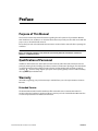
Puritan Bennett 540™
Ventilator
User’s Manual
Copyright information
Copyright 2009 Nellcor Puritan Bennett LLC. All rights reserved. Puritan Bennett 540™ is a trademark of
Nellcor Puritan Bennett LLC and/or its affiliates.
COVIDIEN, COVIDIEN with Logo and ™ marked brands are trademarks of Covidien AG or an affiliate.
The information contained in this manual is the sole property of Nellcor Puritan Bennett LLC and may not
be duplicated without permission. This manual may be revised or replaced by Nellcor Puritan Bennett LLC
at any time and without notice. You should ensure that you have the most current applicable version of this
manual; if in doubt, contact Puritan Bennett’s Technical Support department or visit the Puritan Bennett
product manual web page at:
http://www.puritanbennett.com/serv/manuals.aspx
While the information set forth herein is believed to be accurate, it is not a substitute for the exercise of
professional judgment.
The ventilator should be operated and serviced only by trained professionals. Nellcor Puritan Bennett LLC’s
sole responsibility with respect to the ventilator, and its use, is as stated in the limited warranty provided.
Nothing in this manual shall limit or restrict in any way Nellcor Puritan Bennett LLC’s right to revise or
otherwise change or modify the equipment (including its software) described herein, without notice. In the
absence of an express, written agreement to the contrary, Nellcor Puritan Bennett LLC has no obligation to
furnish any such revisions, changes, or modifications to the owner or user of the equipment (including its
software) described herein.
Contents
Preface . . . . . . . . . . . . . . . . . . . . . . . . . . . . . . . . . . . . . . . . . . . . . . . . . . . . . . . . . . . . . . . . . . . . .
Preface–1
1 Safety Information. . . . . . . . . . . . . . . . . . . . . . . . . . . . . . . . . . . . . . . . . . . . . . . . . . . . . . . . . . . . . . .
1.1
1.2
1.3
1.4
1.5
1–1
Definitions. . . . . . . . . . . . . . . . . . . . . . . . . . . . . . . . . . . . . . . . . . . . . . . . . . . . . . . . . . . . . . . . . . . . 1–1
Warnings . . . . . . . . . . . . . . . . . . . . . . . . . . . . . . . . . . . . . . . . . . . . . . . . . . . . . . . . . . . . . . . . . . . . . 1–2
Cautions . . . . . . . . . . . . . . . . . . . . . . . . . . . . . . . . . . . . . . . . . . . . . . . . . . . . . . . . . . . . . . . . . . . . . . 1–9
Symbols and Markings . . . . . . . . . . . . . . . . . . . . . . . . . . . . . . . . . . . . . . . . . . . . . . . . . . . . . . . 1–10
Labels / Identification and Instruction Information . . . . . . . . . . . . . . . . . . . . . . . . . . . . 1–13
2 Ventilator Overview . . . . . . . . . . . . . . . . . . . . . . . . . . . . . . . . . . . . . . . . . . . . . . . . . . . . . . . . . . . . .
2.1
2.2
2.3
2.4
2.5
2.6
2.7
2.8
2.9
2.10
2.11
Indications for Use . . . . . . . . . . . . . . . . . . . . . . . . . . . . . . . . . . . . . . . . . . . . . . . . . . . . . . . . . . . .
Contraindications . . . . . . . . . . . . . . . . . . . . . . . . . . . . . . . . . . . . . . . . . . . . . . . . . . . . . . . . . . . . .
Operational Use. . . . . . . . . . . . . . . . . . . . . . . . . . . . . . . . . . . . . . . . . . . . . . . . . . . . . . . . . . . . . . .
Device Classification . . . . . . . . . . . . . . . . . . . . . . . . . . . . . . . . . . . . . . . . . . . . . . . . . . . . . . . . . .
Front Panel . . . . . . . . . . . . . . . . . . . . . . . . . . . . . . . . . . . . . . . . . . . . . . . . . . . . . . . . . . . . . . . . . . .
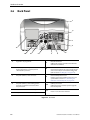
Back Panel . . . . . . . . . . . . . . . . . . . . . . . . . . . . . . . . . . . . . . . . . . . . . . . . . . . . . . . . . . . . . . . . . . . .
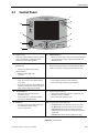
Control Panel . . . . . . . . . . . . . . . . . . . . . . . . . . . . . . . . . . . . . . . . . . . . . . . . . . . . . . . . . . . . . . . . .
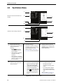
Ventilation Menu . . . . . . . . . . . . . . . . . . . . . . . . . . . . . . . . . . . . . . . . . . . . . . . . . . . . . . . . . . . . .
Alarm Menu . . . . . . . . . . . . . . . . . . . . . . . . . . . . . . . . . . . . . . . . . . . . . . . . . . . . . . . . . . . . . . . . . .
Waveforms Menu . . . . . . . . . . . . . . . . . . . . . . . . . . . . . . . . . . . . . . . . . . . . . . . . . . . . . . . . . . . . .
If Ventilator Failure Occurs . . . . . . . . . . . . . . . . . . . . . . . . . . . . . . . . . . . . . . . . . . . . . . . . . . . .
3 Alarms and Troubleshooting . . . . . . . . . . . . . . . . . . . . . . . . . . . . . . . . . . . . . . . . . . . . . . . . . . .
3.1
3.2
3.3
3.4
3.5
3.6
3.7
3.8
Alarm Level of Priority. . . . . . . . . . . . . . . . . . . . . . . . . . . . . . . . . . . . . . . . . . . . . . . . . . . . . . . . .
Alarm Display . . . . . . . . . . . . . . . . . . . . . . . . . . . . . . . . . . . . . . . . . . . . . . . . . . . . . . . . . . . . . . . . .
Alarm Logs Menu . . . . . . . . . . . . . . . . . . . . . . . . . . . . . . . . . . . . . . . . . . . . . . . . . . . . . . . . . . . . .
Silencing the Audible Portion of Alarms. . . . . . . . . . . . . . . . . . . . . . . . . . . . . . . . . . . . . . . .
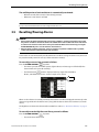
Resetting/Pausing Alarms . . . . . . . . . . . . . . . . . . . . . . . . . . . . . . . . . . . . . . . . . . . . . . . . . . . . .
Re-activating Alarms . . . . . . . . . . . . . . . . . . . . . . . . . . . . . . . . . . . . . . . . . . . . . . . . . . . . . . . . . .
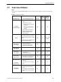
Overview of Alarms . . . . . . . . . . . . . . . . . . . . . . . . . . . . . . . . . . . . . . . . . . . . . . . . . . . . . . . . . . .
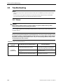
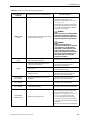
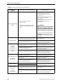
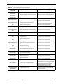
Troubleshooting . . . . . . . . . . . . . . . . . . . . . . . . . . . . . . . . . . . . . . . . . . . . . . . . . . . . . . . . . . . . .
3.8.1 Alarms. . . . . . . . . . . . . . . . . . . . . . . . . . . . . . . . . . . . . . . . . . . . . . . . . . . . . . . . . . . . . . . .
3.8.2 Other Problems . . . . . . . . . . . . . . . . . . . . . . . . . . . . . . . . . . . . . . . . . . . . . . . . . . . . . .
4 Installation and Assembly . . . . . . . . . . . . . . . . . . . . . . . . . . . . . . . . . . . . . . . . . . . . . . . . . . . . . .
4.1
4.2
4.3
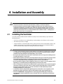
Installing the Ventilator . . . . . . . . . . . . . . . . . . . . . . . . . . . . . . . . . . . . . . . . . . . . . . . . . . . . . . .
Connecting to External AC Power. . . . . . . . . . . . . . . . . . . . . . . . . . . . . . . . . . . . . . . . . . . . . .
Connecting to an External DC Power Source . . . . . . . . . . . . . . . . . . . . . . . . . . . . . . . . . . .
Puritan Bennett 540™ Ventilator User’s Manual
2–1
2–1
2–1
2–2
2–2
2–3
2–4
2–5
2–6
2–7
2–8
2–8
3–1
3–1
3–2
3–3
3–4
3–5
3–6
3–7
3–14
3–14
3–21
4–1
4–1
4–2
4–5
iii
Contents
4.4
Patient Circuit. . . . . . . . . . . . . . . . . . . . . . . . . . . . . . . . . . . . . . . . . . . . . . . . . . . . . . . . . . . . . . . . .
4.4.1 Choosing the Patient Circuit Type . . . . . . . . . . . . . . . . . . . . . . . . . . . . . . . . . . . . . .
4.4.2 Installing the Patient Circuit . . . . . . . . . . . . . . . . . . . . . . . . . . . . . . . . . . . . . . . . . . . .
4.5 Filters . . . . . . . . . . . . . . . . . . . . . . . . . . . . . . . . . . . . . . . . . . . . . . . . . . . . . . . . . . . . . . . . . . . . . . .
4.6 Humidifier . . . . . . . . . . . . . . . . . . . . . . . . . . . . . . . . . . . . . . . . . . . . . . . . . . . . . . . . . . . . . . . . . . .
4.7 Exhalation Block . . . . . . . . . . . . . . . . . . . . . . . . . . . . . . . . . . . . . . . . . . . . . . . . . . . . . . . . . . . . .
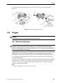
4.8 Oxygen . . . . . . . . . . . . . . . . . . . . . . . . . . . . . . . . . . . . . . . . . . . . . . . . . . . . . . . . . . . . . . . . . . . . . .
4.8.1 Administering Oxygen . . . . . . . . . . . . . . . . . . . . . . . . . . . . . . . . . . . . . . . . . . . . . . . .
4.8.2 Connecting the Oxygen Supply . . . . . . . . . . . . . . . . . . . . . . . . . . . . . . . . . . . . . . .
4.9 Mounting the Ventilator on a Wheelchair . . . . . . . . . . . . . . . . . . . . . . . . . . . . . . . . . . . . .
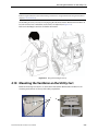
4.10 Mounting the Ventilator on the Utility Cart. . . . . . . . . . . . . . . . . . . . . . . . . . . . . . . . . . . .
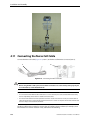
4.11 Connecting the Nurse Call Cable . . . . . . . . . . . . . . . . . . . . . . . . . . . . . . . . . . . . . . . . . . . . .
4–6
4–7
4–7
4–10
4–11
4–12
4–13
4–13
4–14
4–16
4–17
4–18
5 Operating Procedures . . . . . . . . . . . . . . . . . . . . . . . . . . . . . . . . . . . . . . . . . . . . . . . . . . . . . . . . . . .
5–1
5–1
5–2
5–4
5–5
5.1
5.2
5.3
5.4
Turning on The Ventilator . . . . . . . . . . . . . . . . . . . . . . . . . . . . . . . . . . . . . . . . . . . . . . . . . . . . .
Starting Ventilation . . . . . . . . . . . . . . . . . . . . . . . . . . . . . . . . . . . . . . . . . . . . . . . . . . . . . . . . . . .
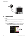
Stopping Ventilation . . . . . . . . . . . . . . . . . . . . . . . . . . . . . . . . . . . . . . . . . . . . . . . . . . . . . . . . . .
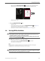
Turning Off the Ventilator . . . . . . . . . . . . . . . . . . . . . . . . . . . . . . . . . . . . . . . . . . . . . . . . . . . . .
6 Internal Battery . . . . . . . . . . . . . . . . . . . . . . . . . . . . . . . . . . . . . . . . . . . . . . . . . . . . . . . . . . . . . . . . . .
6.1
6.2
6.3
6.4
6.5
6.6
Battery Capacity . . . . . . . . . . . . . . . . . . . . . . . . . . . . . . . . . . . . . . . . . . . . . . . . . . . . . . . . . . . . . .
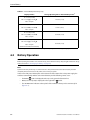
Battery Operation . . . . . . . . . . . . . . . . . . . . . . . . . . . . . . . . . . . . . . . . . . . . . . . . . . . . . . . . . . . . .
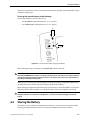
Testing the Battery . . . . . . . . . . . . . . . . . . . . . . . . . . . . . . . . . . . . . . . . . . . . . . . . . . . . . . . . . . . .
Recharging the Battery . . . . . . . . . . . . . . . . . . . . . . . . . . . . . . . . . . . . . . . . . . . . . . . . . . . . . . . .
Storing the Battery . . . . . . . . . . . . . . . . . . . . . . . . . . . . . . . . . . . . . . . . . . . . . . . . . . . . . . . . . . . .
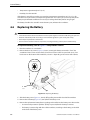
Replacing the Battery . . . . . . . . . . . . . . . . . . . . . . . . . . . . . . . . . . . . . . . . . . . . . . . . . . . . . . . . .
7 Cleaning . . . . . . . . . . . . . . . . . . . . . . . . . . . . . . . . . . . . . . . . . . . . . . . . . . . . . . . . . . . . . . . . . . . . . . . . . .
7.1
7.2
Cleaning the Ventilator. . . . . . . . . . . . . . . . . . . . . . . . . . . . . . . . . . . . . . . . . . . . . . . . . . . . . . . .
Cleaning the Accessories . . . . . . . . . . . . . . . . . . . . . . . . . . . . . . . . . . . . . . . . . . . . . . . . . . . . . .
8 Routine Maintenance . . . . . . . . . . . . . . . . . . . . . . . . . . . . . . . . . . . . . . . . . . . . . . . . . . . . . . . . . . . .
8.1
8.2
8.3
Replacing the Air Inlet Filter . . . . . . . . . . . . . . . . . . . . . . . . . . . . . . . . . . . . . . . . . . . . . . . . . . .
Recommended Schedule of Maintenance. . . . . . . . . . . . . . . . . . . . . . . . . . . . . . . . . . . . . .
Service Assistance. . . . . . . . . . . . . . . . . . . . . . . . . . . . . . . . . . . . . . . . . . . . . . . . . . . . . . . . . . . . .
A Specifications . . . . . . . . . . . . . . . . . . . . . . . . . . . . . . . . . . . . . . . . . . . . . . . . . . . . . . . . . . . . . . . . . . . .
A.1
A.2
A.3
A.4
A.5
A.6
A.7
A.8
iv
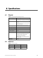
Physical . . . . . . . . . . . . . . . . . . . . . . . . . . . . . . . . . . . . . . . . . . . . . . . . . . . . . . . . . . . . . . . . . . . . . .
Electrical . . . . . . . . . . . . . . . . . . . . . . . . . . . . . . . . . . . . . . . . . . . . . . . . . . . . . . . . . . . . . . . . . . . . .
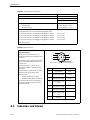
Indicators and Alarms . . . . . . . . . . . . . . . . . . . . . . . . . . . . . . . . . . . . . . . . . . . . . . . . . . . . . . . . .
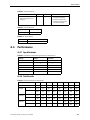
Performance . . . . . . . . . . . . . . . . . . . . . . . . . . . . . . . . . . . . . . . . . . . . . . . . . . . . . . . . . . . . . . . . .
A.4.1 Specifications. . . . . . . . . . . . . . . . . . . . . . . . . . . . . . . . . . . . . . . . . . . . . . . . . . . . . . . . . .
A.4.2 Test Results . . . . . . . . . . . . . . . . . . . . . . . . . . . . . . . . . . . . . . . . . . . . . . . . . . . . . . . . . . .
Monitored Parameters . . . . . . . . . . . . . . . . . . . . . . . . . . . . . . . . . . . . . . . . . . . . . . . . . . . . . . . .
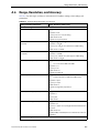
Range, Resolution, and Accuracy . . . . . . . . . . . . . . . . . . . . . . . . . . . . . . . . . . . . . . . . . . . . . .
Environmental . . . . . . . . . . . . . . . . . . . . . . . . . . . . . . . . . . . . . . . . . . . . . . . . . . . . . . . . . . . . . .
Pneumatic . . . . . . . . . . . . . . . . . . . . . . . . . . . . . . . . . . . . . . . . . . . . . . . . . . . . . . . . . . . . . . . . . .
6–1
6–1
6–2
6–4
6–4
6–5
6–6
7–1
7–1
7–2
8–1
8–1
8–2
8–3
A–1
A–1
A–1
A–2
A–3
A–3
A–3
A–4
A–5
A–12
A–12
Puritan Bennett 540™ Ventilator User’s Manual
Contents
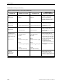
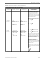
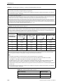
A.9 Manufacturer’s Declaration. . . . . . . . . . . . . . . . . . . . . . . . . . . . . . . . . . . . . . . . . . . . . . . . . . .
A.10 Standards Compliance and IEC Classification . . . . . . . . . . . . . . . . . . . . . . . . . . . . . . . . .
A–13
A–17
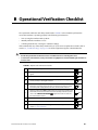
B Operational Verification Checklist . . . . . . . . . . . . . . . . . . . . . . . . . . . . . . . . . . . . . . . . . . . . .
B–1
C Unpacking and Preparation . . . . . . . . . . . . . . . . . . . . . . . . . . . . . . . . . . . . . . . . . . . . . . . . . . . .
C–1
D Modes and Breath Types . . . . . . . . . . . . . . . . . . . . . . . . . . . . . . . . . . . . . . . . . . . . . . . . . . . . . . . .
Modes of Ventilation . . . . . . . . . . . . . . . . . . . . . . . . . . . . . . . . . . . . . . . . . . . . . . . . . . . . . . . . . .
D.1.1 Assist/Control (A/C) Modes. . . . . . . . . . . . . . . . . . . . . . . . . . . . . . . . . . . . . . . . . . . . .
D.1.2 SIMV Modes . . . . . . . . . . . . . . . . . . . . . . . . . . . . . . . . . . . . . . . . . . . . . . . . . . . . . . . . . . .
D.1.3 CPAP Mode . . . . . . . . . . . . . . . . . . . . . . . . . . . . . . . . . . . . . . . . . . . . . . . . . . . . . . . . . . . .
D.1.4 PSV/CPAP Mode . . . . . . . . . . . . . . . . . . . . . . . . . . . . . . . . . . . . . . . . . . . . . . . . . . . . . . .
D–1
D–1
D–1
D–1
D–1
D–2
E Parts and Accessories. . . . . . . . . . . . . . . . . . . . . . . . . . . . . . . . . . . . . . . . . . . . . . . . . . . . . . . . . . . .
E–1
F Glossary . . . . . . . . . . . . . . . . . . . . . . . . . . . . . . . . . . . . . . . . . . . . . . . . . . . . . . . . . . . . . . . . . . . . . . . . . .
F–1
D.1
Index . . . . . . . . . . . . . . . . . . . . . . . . . . . . . . . . . . . . . . . . . . . . . . . . . . . . . . . . . . . . . . . . . . . . . . . . . .
Puritan Bennett 540™ Ventilator User’s Manual
Index–7
v
This page intentionally blank
Figures
Figure 1-1.
Figure 1-2.
Figure 1-3.
Figure 1-4.
Figure 1-5.
Figure 2-1.
Figure 2-2.
Figure 2-3.
Figure 2-4.
Figure 2-5.
Figure 2-6.
Figure 3-1.
Figure 4-1.
Figure 4-2.
Figure 4-3.
Figure 4-4.
Figure 4-5.
Figure 4-6.
Figure 4-7.
Figure 4-8.
Figure 4-9.
Figure 4-10.
Figure 4-11.
Figure 4-12.
Figure 4-13.
Figure 4-14.
Figure 4-15.
Figure 4-16.
Figure 4-17.
Figure 4-18.
Figure 5-1.
Figure 5-2.
Figure 5-3.
Figure 5-4.
Figure 6-1.
Figure 6-2.
Figure 6-3.
Figure 8-1.
Figure C-1.
Figure C-2.
Locations of Labels – Top-Front View . . . . . . . . . . . . . . . . . . . . . . . . . . . . . . . . . . . . . . . . . . . .
Locations of Labels – Front-Left View . . . . . . . . . . . . . . . . . . . . . . . . . . . . . . . . . . . . . . . . . . . .
Location of Labels – Front-Right View. . . . . . . . . . . . . . . . . . . . . . . . . . . . . . . . . . . . . . . . . . . .
Location of Labels and Markings – Back-Left View . . . . . . . . . . . . . . . . . . . . . . . . . . . . . . . .
Location of Labels – Bottom-Front View . . . . . . . . . . . . . . . . . . . . . . . . . . . . . . . . . . . . . . . . .
Front Panel . . . . . . . . . . . . . . . . . . . . . . . . . . . . . . . . . . . . . . . . . . . . . . . . . . . . . . . . . . . . . . . . . . . . . .
Back Panel . . . . . . . . . . . . . . . . . . . . . . . . . . . . . . . . . . . . . . . . . . . . . . . . . . . . . . . . . . . . . . . . . . . . . . .
Control Panel . . . . . . . . . . . . . . . . . . . . . . . . . . . . . . . . . . . . . . . . . . . . . . . . . . . . . . . . . . . . . . . . . . . .
Ventilation Menu Display. . . . . . . . . . . . . . . . . . . . . . . . . . . . . . . . . . . . . . . . . . . . . . . . . . . . . . . . .
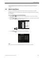
Alarm Menu . . . . . . . . . . . . . . . . . . . . . . . . . . . . . . . . . . . . . . . . . . . . . . . . . . . . . . . . . . . . . . . . . . . . .
Waveforms Menu . . . . . . . . . . . . . . . . . . . . . . . . . . . . . . . . . . . . . . . . . . . . . . . . . . . . . . . . . . . . . . . .
Alarm Displays . . . . . . . . . . . . . . . . . . . . . . . . . . . . . . . . . . . . . . . . . . . . . . . . . . . . . . . . . . . . . . . . . . .
AC Power Cable Holder . . . . . . . . . . . . . . . . . . . . . . . . . . . . . . . . . . . . . . . . . . . . . . . . . . . . . . . . . .
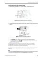
Inserting the Power Cable Holder Into the Notch . . . . . . . . . . . . . . . . . . . . . . . . . . . . . . . . . .
Power Cable Connected to the Ventilator . . . . . . . . . . . . . . . . . . . . . . . . . . . . . . . . . . . . . . . . .
Power Indicators . . . . . . . . . . . . . . . . . . . . . . . . . . . . . . . . . . . . . . . . . . . . . . . . . . . . . . . . . . . . . . . . .
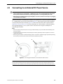
Connecting the Ventilator to an External DC Power Source . . . . . . . . . . . . . . . . . . . . . . . .
Connecting the DC Power Cable to the Ventilator . . . . . . . . . . . . . . . . . . . . . . . . . . . . . . . . .
Single Limb Patient Circuit . . . . . . . . . . . . . . . . . . . . . . . . . . . . . . . . . . . . . . . . . . . . . . . . . . . . . . .
Double Limb Patient Circuit . . . . . . . . . . . . . . . . . . . . . . . . . . . . . . . . . . . . . . . . . . . . . . . . . . . . . .
Close-up of Exhalation Valve Tube and Proximal Pressure Tube. . . . . . . . . . . . . . . . . . . .
Air Inlet Filter . . . . . . . . . . . . . . . . . . . . . . . . . . . . . . . . . . . . . . . . . . . . . . . . . . . . . . . . . . . . . . . . . . .
Bacteria Filter . . . . . . . . . . . . . . . . . . . . . . . . . . . . . . . . . . . . . . . . . . . . . . . . . . . . . . . . . . . . . . . . . . .
Humidifier . . . . . . . . . . . . . . . . . . . . . . . . . . . . . . . . . . . . . . . . . . . . . . . . . . . . . . . . . . . . . . . . . . . . . .
Removing the Exhalation Block. . . . . . . . . . . . . . . . . . . . . . . . . . . . . . . . . . . . . . . . . . . . . . . . . .
Rear Panel Oxygen Connector . . . . . . . . . . . . . . . . . . . . . . . . . . . . . . . . . . . . . . . . . . . . . . . . . . .
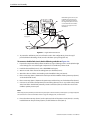
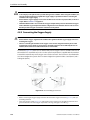
Connecting the Oxygen Supply System. . . . . . . . . . . . . . . . . . . . . . . . . . . . . . . . . . . . . . . . . .
Disconnecting the Oxygen Supply System . . . . . . . . . . . . . . . . . . . . . . . . . . . . . . . . . . . . . . .
Using the Dual Bag Accessory . . . . . . . . . . . . . . . . . . . . . . . . . . . . . . . . . . . . . . . . . . . . . . . . . . .
Connecting the Nurse Call Cable . . . . . . . . . . . . . . . . . . . . . . . . . . . . . . . . . . . . . . . . . . . . . . . .
Turning on the Ventilator . . . . . . . . . . . . . . . . . . . . . . . . . . . . . . . . . . . . . . . . . . . . . . . . . . . . . . . .
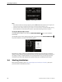
Welcome Menu Screen. . . . . . . . . . . . . . . . . . . . . . . . . . . . . . . . . . . . . . . . . . . . . . . . . . . . . . . . . . .
Prompt to Start Ventilation . . . . . . . . . . . . . . . . . . . . . . . . . . . . . . . . . . . . . . . . . . . . . . . . . . . . . . .
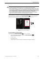
Starting Ventilation . . . . . . . . . . . . . . . . . . . . . . . . . . . . . . . . . . . . . . . . . . . . . . . . . . . . . . . . . . . . . .
Internal Battery Indicator . . . . . . . . . . . . . . . . . . . . . . . . . . . . . . . . . . . . . . . . . . . . . . . . . . . . . . . .
Power Indicators When Charging the Battery . . . . . . . . . . . . . . . . . . . . . . . . . . . . . . . . . . . . .
Replacing the Battery . . . . . . . . . . . . . . . . . . . . . . . . . . . . . . . . . . . . . . . . . . . . . . . . . . . . . . . . . . . .
Replacing the Air Inlet Filter . . . . . . . . . . . . . . . . . . . . . . . . . . . . . . . . . . . . . . . . . . . . . . . . . . . . . .
Puritan Bennett 540™ Portable Ventilator . . . . . . . . . . . . . . . . . . . . . . . . . . . . . . . . . . . . . . . . .
Dual Bag. . . . . . . . . . . . . . . . . . . . . . . . . . . . . . . . . . . . . . . . . . . . . . . . . . . . . . . . . . . . . . . . . . . . . . . . .
Puritan Bennett 540™ Ventilator User’s Manual
1–16
1–16
1–17
1–17
1–18
2–3
2–4
2–5
2–6
2–7
2–8
3–2
4–2
4–3
4–3
4–4
4–5
4–6
4–8
4–9
4–9
4–11
4–11
4–12
4–13
4–14
4–15
4–15
4–17
4–18
5–1
5–2
5–3
5–4
6–3
6–5
6–6
8–2
C–2
C–3
vii
This page intentionally blank
Tables
Table 1-1.
Table 1-2.
Table 3-1.
Table 3-2.
Table 3-3.
Table 6-1.
Table 7-1.
Table 8-1.
Table A-1.
Table A-2.
Table A-3.
Table A-4.
Table A-5.
Table A-6.
Table A-7.
Table A-8.
Table A-9.
Table A-10.
Table A-11.
Table A-12.
Table A-13.
Table A-14.
Table A-15.
Table A-16.
Table A-17.
Table A-18.
Table A-19.
Table A-20.
Table A-21.
Table A-22.
Table A-23.
Table B-1.
Table E-1.
Table E-2.
Ventilator Symbols . . . . . . . . . . . . . . . . . . . . . . . . . . . . . . . . . . . . . . . . . . . . . . . . . . . . . . . . . . . . . .
Ventilator Labels and Markings . . . . . . . . . . . . . . . . . . . . . . . . . . . . . . . . . . . . . . . . . . . . . . . . . . .
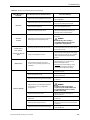
Overview of Alarms . . . . . . . . . . . . . . . . . . . . . . . . . . . . . . . . . . . . . . . . . . . . . . . . . . . . . . . . . . . . . . .
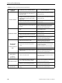
Alarms and Corrective Actions . . . . . . . . . . . . . . . . . . . . . . . . . . . . . . . . . . . . . . . . . . . . . . . . . . .
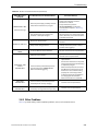
Additional Problems and Corrective Actions . . . . . . . . . . . . . . . . . . . . . . . . . . . . . . . . . . . . . .
Internal Battery Reserve Capacity. . . . . . . . . . . . . . . . . . . . . . . . . . . . . . . . . . . . . . . . . . . . . . . . . .
Approved Cleaning Solutions for Exterior Ventilator Surfaces . . . . . . . . . . . . . . . . . . . . . .
Consumables and Replacement Intervals . . . . . . . . . . . . . . . . . . . . . . . . . . . . . . . . . . . . . . . . . .
Physical Description (Excluding Accessories). . . . . . . . . . . . . . . . . . . . . . . . . . . . . . . . . . . . . . .
AC Electrical Supply. . . . . . . . . . . . . . . . . . . . . . . . . . . . . . . . . . . . . . . . . . . . . . . . . . . . . . . . . . . . . . .
Internal Lithium Ion Battery . . . . . . . . . . . . . . . . . . . . . . . . . . . . . . . . . . . . . . . . . . . . . . . . . . . . . . .
Remote Alarm . . . . . . . . . . . . . . . . . . . . . . . . . . . . . . . . . . . . . . . . . . . . . . . . . . . . . . . . . . . . . . . . . . . .
Power Indicators. . . . . . . . . . . . . . . . . . . . . . . . . . . . . . . . . . . . . . . . . . . . . . . . . . . . . . . . . . . . . . . . . .
Alarm Indicators . . . . . . . . . . . . . . . . . . . . . . . . . . . . . . . . . . . . . . . . . . . . . . . . . . . . . . . . . . . . . . . . . .
Audio Alarms . . . . . . . . . . . . . . . . . . . . . . . . . . . . . . . . . . . . . . . . . . . . . . . . . . . . . . . . . . . . . . . . . . . . .
Performance Parameter Specifications and Tolerances . . . . . . . . . . . . . . . . . . . . . . . . . . . . .
Volume Performance Test Results . . . . . . . . . . . . . . . . . . . . . . . . . . . . . . . . . . . . . . . . . . . . . . . . .
Monitored Parameter Specifications and Tolerances . . . . . . . . . . . . . . . . . . . . . . . . . . . . . . .
Ventilator Range, Resolution, and Accuracy . . . . . . . . . . . . . . . . . . . . . . . . . . . . . . . . . . . . . . . .
Environmental Conditions for Storage or Transport . . . . . . . . . . . . . . . . . . . . . . . . . . . . . . .
Environmental Conditions for Operation . . . . . . . . . . . . . . . . . . . . . . . . . . . . . . . . . . . . . . . . .
Airway Resistances. . . . . . . . . . . . . . . . . . . . . . . . . . . . . . . . . . . . . . . . . . . . . . . . . . . . . . . . . . . . . . .
Patient Circuit Resistances . . . . . . . . . . . . . . . . . . . . . . . . . . . . . . . . . . . . . . . . . . . . . . . . . . . . . . .
Air Inlet Resistance (Filter). . . . . . . . . . . . . . . . . . . . . . . . . . . . . . . . . . . . . . . . . . . . . . . . . . . . . . . .
Oxygen Inlet Specifications . . . . . . . . . . . . . . . . . . . . . . . . . . . . . . . . . . . . . . . . . . . . . . . . . . . . . .
Performance Specifications . . . . . . . . . . . . . . . . . . . . . . . . . . . . . . . . . . . . . . . . . . . . . . . . . . . . . .
Electromagnetic Emissions . . . . . . . . . . . . . . . . . . . . . . . . . . . . . . . . . . . . . . . . . . . . . . . . . . . . . . .
Electromagnetic Immunity . . . . . . . . . . . . . . . . . . . . . . . . . . . . . . . . . . . . . . . . . . . . . . . . . . . . . . .
Electromagnetic Immunity – Conducted and Radiated RF . . . . . . . . . . . . . . . . . . . . . . . . .
Recommended Separation Distances. . . . . . . . . . . . . . . . . . . . . . . . . . . . . . . . . . . . . . . . . . . . .
Compliant Cables and Accessories. . . . . . . . . . . . . . . . . . . . . . . . . . . . . . . . . . . . . . . . . . . . . . . .
Operational Verification Checklist . . . . . . . . . . . . . . . . . . . . . . . . . . . . . . . . . . . . . . . . . . . . . . . . .
List of Consumables and Accessories . . . . . . . . . . . . . . . . . . . . . . . . . . . . . . . . . . . . . . . . . . . . . .
List of Circuits. . . . . . . . . . . . . . . . . . . . . . . . . . . . . . . . . . . . . . . . . . . . . . . . . . . . . . . . . . . . . . . . . . . . .
Puritan Bennett 540™ Ventilator User’s Manual
1–10
1–14
3–7
3–14
3–22
6–2
7–1
8–2
A–1
A–1
A–2
A–2
A–3
A–3
A–3
A–3
A–3
A–4
A–5
A–12
A–12
A–12
A–12
A–12
A–12
A–13
A–13
A–14
A–15
A–16
A–16
B–1
E–1
E–2
ix
This page intentionally blank
Preface
Purpose of This Manual
This manual contains important information regarding the safe operation of your Puritan Bennett
540™ Ventilator. Your ventilator is an electrical device that can provide years of useful service with the
proper care, as described in this manual.
Ensure that you read and understand the instructions contained in this manual before operating the
ventilator.
WARNING
Before operating the ventilator, read, understand, and strictly follow the information contained in
Chapter 1, “Safety Information”.
Qualification of Personnel
Installation and maintenance of the device must be made by authorized and trained personnel. In
particular, training for the handling of products sensitive to electrostatic discharges must include the
use of Electrostatic Discharge (ESD) protection devices and knowledge of the following symbol’s
meaning:
, as well as using original spare parts and respecting quality assurance and traceability
rules approved by Puritan Bennett.
Warranty
Information regarding your product warranty is available from your sales representative or Puritan
Bennett.
Extended Service
The Puritan Bennett 540™ Portable Ventilator offers extended service contracts/warranties for
purchase when the ventilator is purchased. Please contact your local Covidien/Puritan Bennett Sales
or Service Representative for additional information.
Puritan Bennett 540™ Ventilator User’s Manual
Preface-1
Preface
For online technical support, visit the SolvITSM Center
Knowledge Base by clicking the link at
http://www.puritanbennett.com. Here, you will find answers
to frequently asked questions about the Puritan Bennett
540™ Ventilator and other Puritan Bennett products 24
hours a day, 7 days a week. If you require further assistance,
contact your local Puritan Bennett representative or call
Puritan Bennett Technical Support at 1.800.255.6774.
Preface-2
Puritan Bennett 540™ Ventilator User’s Manual
1 Safety Information
1.1
Definitions
This manual uses three indicators to highlight critical information: Warning, Caution, and Note. They are
defined as follows:
WARNING
Indicates a condition that can endanger the patient or the ventilator operator.
Caution
Indicates a condition that can damage the equipment.
Note:
Indicates points of particular emphasis, that make operation of the ventilator more efficient or convenient.
It is essential to read, understand and follow these instructions before using the Puritan Bennett 540™ Ventilator.
In order to use the ventilator correctly and efficiently and to help prevent incidents, please pay particular attention to sections 1.2, “Warnings” and 1.3, “Cautions” as well as all warnings and cautions contained throughout this
manual.
Puritan Bennett 540™ Ventilator User’s Manual
1-1
Safety Information
1.2
Warnings
General Precautions For Use
WARNING
• Federal law restricts this device to sale by or on the order of a licensed physician.
1-2
•
•
•
The ventilator must be used only under the responsibility and on the prescription of a doctor.
•
While the ventilator is in use, an alternative means of ventilation should always be available in the
event of a ventilator problem. This is particularly true for ventilator-dependent patients.
Supplementary observation, appropriate for the patient's condition, is also recommended.
•
To ensure that ventilation continues uninterrupted, ensure alternative power sources are available (AC
power source, extra batteries, or an auxiliary DC car adapter). Be prepared for the possibility of power
failure by having an alternative means of ventilation ready for use—particularly for ventilatordependent patients.
•
.Do not allow a patient to remain connected to the ventilator when ventilation is stopped, because a
substantial quantity of expiratory gas, primarily carbon dioxide, may be inhaled by the patient. In
some circumstances, inhaling carbon dioxide may lead to under-ventilation, suffocation, and serious
injury or death.
•
•
The ventilator must not be used with flammable anesthetic substances.
•
You must start the ventilator and allow it to complete one full breath cycle prior to connecting the
patient. Do not connect the patient before this cycle completes.
•
.Due to its limited internal battery’s reserve capacity, the ventilator should only be operated
occasionally while powered by its internal battery. Ensure that the internal battery never becomes fully
discharged.
•
A ventilator-dependent patient should always be monitored by trained and competent medical
personnel. Ensure that the patient’s caregiver is able and prepared to take suitable action in the event
the ventilator identifies an alarmed condition or experiences a problem.
•
Before dispensing the ventilator to caregivers or the patient for home use, ensure the Locking Key is
activated so that critical ventilator settings are not modified.
•
•
•
Do not perform ventilator alarm tests while the patient is connected to the ventilator.
•
When an alarm condition is triggered, or there is evidence of a patient-ventilator fault or problem,
examine the patient first before examining the ventilator.
•
A continuous alarm condition will be activated if the ventilator power switch is turned off while
ventilation is in progress. When the power switch is turned back on again, the ventilation will resume
without having to press the VENTILATION ON/OFF button.
•
To reduce the risk of infection, wash your hands thoroughly before and after handling the ventilator or
its accessories.
•
A patient treated by mechanical ventilation is highly vulnerable to the risks of infection. Dirty or
contaminated equipment is a potential source of infection. Clean the ventilator and its accessories
regularly and systematically before and after each use and following any maintenance procedure to
reduce the risks of infection. The use of a bacterial filter at the ventilator’s outlet—or both ports if a
double-limb circuit is used—is recommended. Refer to chapter 7, “Cleaning”.
•
Handle the ventilator with care during and after use, particularly when room temperatures are high.
Some ventilator surfaces may become hot, even if safety specifications are not exceeded.
The ventilator must be used according to its intended use. Refer to section 2.1, “Indications for Use”.
Be aware this manual describes how to respond to ventilator alarms, but it does NOT tell you how to
respond to the patient.
Do not start ventilation until you ensure that the device is suitably assembled, that the air inlet filter is
properly installed and is not obstructed, and that there is proper clearance all around the unit. Also
ensure that the patient circuit is suitably connected to both the ventilator and the patient and that the
patient circuit, including all hoses, is not damaged or obstructed.
Verify the functionality of the alarms conditions before connecting the patient to the ventilator.
If the ventilator fails the alarm tests or if you cannot complete the tests, refer to
chapter 3, “Alarms and Troubleshooting” or call your equipment supplier or Puritan Bennett.
Puritan Bennett 540™ Ventilator User’s Manual
Warnings
General Precautions For Installation
WARNING
Environment:
•
Because the internal Lithium-ion battery of the Puritan Bennett 540™ Ventilator contains more than 8g
(equivalent) lithium and has a power-rating greater than 100 Wh (watt-hour), it is categorized as
Hazardous Material (Dangerous Good), Class 9- Miscellaneous, even though the ventilator meets
current safety standards.
The ventilator, because of this categorization, is subject to strict transport conditions under the US
Department of Transportation (US DOT) regulations for the transport of hazardous materials (49 CFR
173.185).
As US DOT regulations cover commercial transportation only, there are two groups that can be
exempted from these regulations. The first group consists of private individuals, providing that the
goods are for their own personal use and measures have been taken to prevent leakage. The second
group consists of persons that transport the goods because they need the product to execute their
job(s). The later group is able to carry/transport certain hazardous materials, such as the Puritan
Bennett 540™ Ventilator and the associated Lithium-ion battery(ies), under the established Materials of
Trade (MOT) provisions detailed in 49 CFR 173.6. For any other group or purpose, transport must be
compliant with the applicable Hazardous Materials/Dangerous Goods regulations specific to the
origin/destination and mode of transport. Air transport of the Puritan Bennett 540™ Ventilator in only
allowed as carry-on baggage, which may include up to two (2) individually packaged spare Lithium-ion
batteries (it is recommended that users verify specific requirements/limitations with the airline carriers
as to which measures to take before the voyage).
•
Even though the Puritan Bennett 540™ Ventilator meets current safety standards, the internal Lithiumion battery of this device contains more than 8g equivalent lithium and exceeds a power-rating of 100
Wh (watt-hour) and therefore considered to be a Hazardous Material (Dangerous Good), Class 9 Miscellaneous when transported in commerce. As such, the Puritan Bennett 540™ Ventilator and/or the
associated Lithium-ion battery are subject to strict transport conditions established by the US
Department of Transportation (49 CFR 173.185) as well as other international transportation
regulations. This classification and regulatory requirements may vary depending upon the country and
mode of transport. In addition, air transport of the Puritan Bennett 540™ Ventilator is only allowed as
carry-on baggage, which may include up to two (2) individually packaged spare Lithium-ion batteries.
(it is recommended that users verify specific requirements/limitations with the airline carriers as to
which measures to take before the voyage).
•
•
To minimize the risk of damage, you must use the ventilator Dual Bag to transport the ventilator.
•
To avoid damage to the ventilator, fluids must not be allowed to enter the device, particularly through
the air inlet filter or the cooling apertures located in the side, rear, and bottom panels of the ventilator.
•
To ensure correct and lasting operation of the device, ensure that the ventilator is installed and
operated in the environmental conditions recommended in Appendix A, “Specifications.”
•
Do not operate the ventilator in direct sunlight, near heat sources, outdoors, or near installations
where liquid may pose a risk without first providing adequate protection for the device.
•
Ensure that the ventilator’s immediate surroundings allow for the proper operational connection of the
device without folding, pinching, or damaging any of the required cables or tubes, and that the
connection of the patient circuit to the patient provides for a secure, comfortable fit.
•
Do not place the ventilator in a position where a child can reach it or in any position that might cause it
to fall on the patient or someone else.
•
To ensure correct and lasting operation of the ventilator, ensure that its air circulation holes (main inlet
or cooling) are never obstructed. Place the device in an area where air can freely circulate around the
ventilator and avoid installing it near floating fabrics, such as curtains.
•
If the ventilator has been transported or stored at a temperature that differs more than ± 36 °F (±20 °C)
from the temperature in which it will be operating, the ventilator should be allowed to stabilize in its
operating environment for at least two (2) hours prior to use.
The ventilator should never be immersed in any liquid, and any liquid on the surface of the device
should be wiped away immediately.
Puritan Bennett 540™ Ventilator User’s Manual
1-3
Safety Information
WARNING
Environment (Cont’d):
•
If the room temperature where the device is operated is greater than 95 °F (35 °C), the flow supplied at
the device outlet may exceed 106 °F (41 °C). This may lead to undesirable side effects for the patient. To
avoid injury to the patient move the patient and the ventilator to a cooler location. For more
information, contact Puritan Bennett.
•
The default setting for altitude compensation is YES. Altitude compensation should always be set to
YES for accurate volume delivery calculations at all elevations.
•
To avoid a fire hazard, keep matches, lighted cigarettes, and all other sources of ignition (such as
flammable anesthetics and/or heaters) away from the ventilator and oxygen hoses.
•
If the ambient temperature is above 104 °F (40 °C), the battery's thermal cut-off circuit may prevent the
battery from recharging fully—even if the INTERNAL BAT charging indicator indicates the battery is
completely recharged.
•
Regularly check the cleanliness of the air inlet filter located on the rear of the ventilator. If necessary,
replace the filter before the recommended replacement period is over (see chapter 8, “Routine
Maintenance”). This is particularly important when the ventilator is installed on a wheelchair, because
environmental conditions may cause the filter to become dirty more rapidly.
•
Handle the ventilator with care during and after use, particularly when room temperatures are high.
Some ventilator surfaces may become hot, even if safety specifications are not exceeded.
Electrical Power Supplies:
1-4
•
Never connect your ventilator to an electrical outlet controlled by a wall switch because the power may
be inadvertently turned off.
•
For the AC (“mains”) power cable to be properly secured, the attachment located on the power cable
must be fitted into the power cable holder incorporated in the battery access cover and located under
the AC (mains) power socket. Refer to section 4.2, “Connecting to External AC Power”.
•
The power supply to which the ventilator is connected (both AC and DC) must comply with all
applicable standards and provide electrical power corresponding to the voltage characteristics
inscribed on the rear of the ventilator to ensure correct operation. Refer also to the electrical
specifications found in Appendix A, “Specifications”.
•
Ensure that the ventilator’s internal battery is fully charged before connecting the ventilator to an
external DC power source. Powering the ventilator using an external 12– 30 VDC power source (via the
DC power cable) does not enable charging of its internal battery.
•
Due to its limited internal battery’s reserve capacity, the ventilator should only be operated
occasionally while powered by its internal battery. Ensure that the internal battery never becomes fully
discharged.
•
When using a car auxiliary adapter (cigarette lighter) ensure the car has been started prior to plugging
in the ventilator’s DC adapter.
•
Even if the “INTERNAL BAT“ indicator is off, charge of the battery may sometimes be incomplete
regardless of charge time when the ambient temperature is above 104 °F (40 °C). This is due to the
characteristics of the battery’s internal heat safety device.
•
When the “LOW BATTERY“ alarm is triggered, immediately connect the ventilator to an AC power
supply to maintain ventilation and recharge the internal battery.
•
When replacing the ventilator’s internal battery, the ventilator must be disconnected from all external
power supplies and turned off.
•
•
•
Batteries should be disposed of according to environmental legislation in your country and locality.
Never expose any batteries to direct flame.
Never touch the ventilator’s internal components, including the battery, and the patient
simultaneously.
Puritan Bennett 540™ Ventilator User’s Manual
Warnings
WARNING
Hoses and Accessories:
•
The ventilator must not use, nor be connected to, any anti-static or electrically conductive hoses,
tubing, or conduits. High and Low VTE alarm parameters must be properly set to warn in the event of
patient suffocation.
•
During invasive ventilation (when an artificial airway bypasses the patient’s upper respiratory system),
the patient’s upper respiratory system cannot humidify the incoming air. For this reason, the use of a
humidifier, to minimize drying of the patient’s airways and subsequent irritation and discomfort, must
be used.
•
If exhaled tidal volume or exhaled minute volume measurements are required to ensure correct patient
ventilation a double limb patient circuit configuration must be used in order to detect leaks. In this
case, both the High and Low VTE alarm parameters must be properly set to warn in the event of patient
suffocation.
•
The patient circuit should always be positioned to avoid hindering the patient's movements, to prevent
accidental disconnection, and to minimize the risk of patient strangulation.
•
For pediatric use, ensure that the patient circuit type fits, and, in all respects, is suitable for use with a
child. Use a pediatric circuit for patients that weigh under 53 lb. (23 kg). See Table E-2, List of Circuits,
on page E-2, for a list of recommended patient circuits.
•
Resistance of the exhalation valve and accessories (water traps, filters, and so on) must be as low as
possible.
•
Adding attachments to the ventilator breathing system can cause the pressure during exhalation at the
patient connection port to increase.
•
The exhalation valve must allow rapid discharge of the circuit pressure. Ensure that the exhalation
valve is always clean and its evacuation aperture (exhaust port) is never obstructed.
•
Users must always possess an additional breathing circuit and exhalation valve while using the Puritan
Bennett 540™ Ventilator.
•
•
Consult with your Customer Support representative before attempting to use a heated humidifier.
•
If a heated humidifier is used, you should always monitor the temperature of the air delivered to the
patient. Air delivered from the ventilator that becomes too hot may burn the patient's airway.
•
Adding accessories to the ventilator breathing circuit, such as a humidifier and water trap(s), may result
in a decrease in tidal volume delivered to the patient due to the added compressible volume of the
accessory. Always assure that the patient is receiving the appropriate inspired volume when altering
the breathing circuit configuration.
•
The level of inspiratory resistance of the circuit and accessories (bacteria filter, humidifier, and so on)
must be as low as possible. Settings—particularly the LOW PRESSURE DISCONNECT alarm, High
inspired volume (High VTI), and Low inspired volume (Low VTI) settings—must be periodically
adjusted according to changes in the patient circuit resistance—especially when filters are replaced.
•
To ensure proper performance of the ventilator, use a patient circuit recommended by Puritan Bennett
in this manual; refer to chapter 4, “Installation and Assembly”. The total specified length of the patient
circuit tubing as measured from the ventilator outlet to the ventilator inlet is 3.6 feet (1.10 meters) to
6.6 feet (2.00 meters).
The tubing must conform to all applicable standards and must be fitted with Ø 22 mm terminals that
also conform to all applicable standards. Ensure that both the length and the internal volume of the
patient circuit are appropriate for the tidal volume: a corrugated tube of Ø 22 mm for adult patients,
and a corrugated tube of Ø 15 mm for pediatric patients with a tidal volume lower than 200 ml.
•
•
When using non-invasive ventilation (niv), use a non-vented nose or face mask.
Always position a humidification device so that it is lower than both the ventilator and the patient. Use
water traps, if necessary, to limit water in the patient circuit and periodically empty these water traps.
Before using the Nurse Call system, ensure that its connections are secure and it operates properly. For
more information, contact Puritan Bennett.
Puritan Bennett 540™ Ventilator User’s Manual
1-5
Safety Information
Precautions Regarding Settings
WARNING
• Before starting ventilation, ensure that the device is properly assembled and that the air inlet, cooling
vents, and alarm sound diffusion holes are not obstructed. Ensure also that the patient circuit is of the
proper configuration (double or single limb), properly connected to the ventilator, and that the circuit
hoses are neither damaged nor compressed and contain no obstructions or foreign bodies.
1-6
•
Do not allow a patient to remain connected to the ventilator when ventilation is stopped, because a
substantial quantity of expiratory gas, primarily carbon dioxide, may be inhaled by the patient. In
some circumstances, inhaling carbon dioxide may lead to under-ventilation, suffocation, and serious
injury or death.
•
Alarm volume should be adjusted with respect to the ventilator’s operating environment and so that
the patient's caretakers can hear the alarms. The audible alarm vents located at the front of the device
should never be obstructed. The alarm can be paused with the Alarm Pause function by pressing the
ALARM CONTROL key twice once the alarm has been declared.
•
Monitor the patient's state of health in order to ensure that the ventilator’s settings are always suited to
the patient’s current physiological requirements.
•
In the case of pediatric use, ensure that the adjusted tidal volume is compatible with the needs of the
child.
•
•
Ensure that the tidal volume setting in VC is compatible with the needs of the patient.
•
•
•
If APNEA TIME is set to a value higher than 60/Control R then the APNEA alarm will not activate.
•
A continuous alarm condition will be activated if the ventilator power switch is turned off while
ventilation is in progress. When the power switch is turned back on again, the ventilation will resume
without having to press the VENTILATION ON/OFF button.
Do not conduct the ventilator alarm test while the patient is connected to the ventilator. Switch the
patient to an alternate means of ventilation before testing.
Setting Alarm limits to extreme values can cause the ventilator alarms to malfunction.
Adjustable alarms should not be systematically cancelled; instead, they should be adjusted according
to the needs and condition of the patient.
Puritan Bennett 540™ Ventilator User’s Manual
Warnings
Maintenance Precautions
WARNING
• Never use a ventilator or any components or accessories that appear to be damaged. If any signs of
damage are evident, contact your equipment supplier or Puritan Bennett.
•
If you cannot determine the cause of a problem with your ventilator, contact your equipment supplier.
Do not use the ventilator until the problem has been corrected.
•
Except for replacing the internal battery and cleaning the device, do not try to repair or otherwise
service the ventilator yourself, or modify the ventilator, its components, or accessories. Doing so might
endanger the patient, cause damage to the ventilator, and/or void your warranty. Only qualified
service personnel should attempt repair of the ventilator.
•
•
On a daily basis, ensure the proper connection and operation of the patient circuit.
•
After assembling, cleaning, or reassembling the patient circuit, and on a daily basis, inspect the hoses
and other components to ensure that there are no cracks or leaks and that all connections are secure.
•
Use all cleaning solutions and products with caution. Read and follow the instructions associated with
the cleaning solutions you use to clean your ventilator. Use only those solutions listed in Table 7-1.
•
Do not attempt to repair or otherwise service the ventilator yourself. Doing so might endanger the
patient, damage the ventilator, and/or void your warranty. Only qualified service personnel should
repair or service the ventilator.
•
If the ventilator is damaged or its external housing is not correctly closed or it behaves in a way that is
not described in this manual (excessive noise, heat emission, unusual odor, alarms not triggered during
the start-up procedure), the oxygen and power supplies should be disconnected and use of the device
stopped immediately.
•
The exhalation block is intended for single use by a single patient. It may periodically be cleaned, but it
cannot be disinfected or sterilized. To maintain good measurement quality when used continuously,
trained personnel should clean the exhalation block periodically. The exhalation block should be
changed every 3 months and cannot be reused with any other patient.
•
•
Ensure that the exhalation block is completely dried after cleaning and prior to use.
•
The patient circuit is intended for single use by a single patient and should be changed according to the
manufacturer’s recommendations. Refer to the instructions for use supplied by the manufacturer of the
patient circuit (included with the ventilator) and chapter 4, “Installation and Assembly”.
•
A patient treated by mechanical ventilation is highly vulnerable to the risks of infection. Dirty or
contaminated equipment is a potential source of infection. Clean the ventilator and its accessories
regularly and systematically before and after each use and following any maintenance procedure to
reduce the risks of infection. The use of a bacterial filter at the ventilator’s outlet—or both ports if a
double-limb circuit is used—is recommended. Refer to chapter 7, “Cleaning”.
•
When replacing the ventilator’s internal battery, the ventilator must be disconnected from all external
power supplies and turned off.
•
Never touch the ventilator’s internal components, including the battery, and the patient
simultaneously.
•
Regularly check the cleanliness of the air inlet filter located on the rear of the ventilator. If necessary,
replace the filter before the recommended replacement period is over (see section 10, “Routine
Maintenance in the Clinician’s Manual). This is particularly important when the ventilator is installed on
a wheelchair, because environmental conditions may cause the filter to become dirty more rapidly.
If a problem with the ventilator is suspected, FIRST CHECK THAT THE PATIENT IS NOT IN DANGER. If
necessary, remove the patient from the ventilator and provide an alternative means of ventilation.
When an exhalation block is set up, each time it is removed, or after installing a new exhalation block
on the machine, it is essential that the expiratory flow sensor be recalibrated before the exhalation
block is used; refer to section 10.1, “Calibrating the Expiratory Flow Sensor” in the Clinician’s Manual.
Puritan Bennett 540™ Ventilator User’s Manual
1-7
Safety Information
WARNING
Maintenance Precautions (Cont’d):
•
For environmental protection, the ventilator and its components, whatever their respective conditions
of operation, cannot be disposed of with household waste and must be submitted for suitable selective
collection and possible recycling. Observe all applicable regulations when disposing of the ventilator
and any of its components.
•
If the device is damaged, its external housing is not correctly closed, or it behaves in a way that is not
described in this manual (excessive noise, heat emission, unusual odor, alarms not triggered during the
start-up procedure), the oxygen and power supplies should be disconnected and use of the device
stopped immediately.
•
After replacing the ventilator’s internal battery, push on the battery’s cover from the rear towards the
front to take pressure off the cover mounting brackets, thereby avoiding breakage when the screws are
tightened.
Precautions Regarding Oxygen
WARNING
The ventilator must not be used with flammable anesthetic substances.
•
•
1-8
Oxygen therapy for patients with respiratory failure is a common and effective medical prescription.
However, be aware that excessive oxygen use is likely to lead to serious complications—including, but
not limited to, patient injury.
•
Strictly follow the instructions provided in section 4.8.2, “Connecting the Oxygen Supply”, which
include the use of a flow regulator and special coupler.
•
To avoid injury to the patient and/or possible damage to the ventilator: before using the ventilator, use
a flow meter (flow regulator) to regulate the oxygen supply to specifications before connecting the
ventilator to the oxygen supply.
•
The Puritan Bennett 540™ Ventilator does not include an oxygen analyzer. Always measure the
delivered oxygen with a calibrated oxygen analyzer that features a high and low concentration alarm in
order to ensure that the prescribed oxygen concentration is delivered to the patient.
•
Ensure that the oxygen supply pressure to the machine never exceeds 7.25 psi (49.99 kPa) or a flow of
15 lpm. Refer to Table A-8 on page A-3 for volume and sensitivity tolerances.
•
In the event of an oxygen leak, shut down the supply of oxygen at its source. In addition, remove and/or
keep any incandescent source away from the device, which may be enriched with oxygen. Air the
affected room to bring the oxygen level down to normal.
•
The hose connecting the ventilator to the oxygen source must be designed exclusively for use with
medical-grade oxygen. Under no circumstances should the oxygen hose be modified by the user. In
addition, the hose must be installed without the use of lubricants.
•
Ensure that the only gas supplied to the ventilator through the dedicated oxygen supply connector is
medical-grade oxygen.
•
The coupler must not remain connected to the oxygen connector unless it also connected to a leakproof, external oxygen gas source. When an oxygen supply is not being used with the ventilator,
disconnect the oxygen source completely from the ventilator.
•
To prevent any interference with the internal sensors of the ventilator, do not install a ventilator
humidifier upstream of the ventilator.
Puritan Bennett 540™ Ventilator User’s Manual
Cautions
1.3
Cautions
General Precautions For Use
Caution
• To ensure proper servicing and avoid the possibility of physical injury to personnel or damage to the
ventilator, only qualified personnel should attempt to service the Puritan Bennett 540™ Portable Ventilator.
General Precautions For Installation
Caution
Environment:
•
Avoid using the ventilator, if possible, in dusty environments. Dusty environments may require more vigilant
monitoring, cleaning, and/or replacement of air intake and other filters.
Electrical Power Supplies:
•
•
Before using the ventilator’s internal battery, ensure that the battery is fully charged and that the charge holds.
•
To connect the ventilator to an external power source, first ensure the ventilator’s I/O switch is off (O).
Then, connect the desired power cable to the ventilator. Finally, connect the power cable to the external
power source.
•
To disconnect the ventilator from an external power source, first power-down the ventilator. Then, disconnect
the power cable from the external power source and, finally, the ventilator.
•
•
•
Do not leave power cables lying on the ground where they may pose a hazard.
Do not store the internal battery, either installed within or removed from the ventilator, for more than two (2)
years.
Ensure that the AC power cable is in perfect condition and not compressed.
To connect the ventilator to a Nurse Call device, contact Puritan Bennett to check the ventilator's compatibility
with the Nurse Call device and order a suitable connection cable. Do not use Nurse Call devices that operate
based on the closure of an electrical circuit, because the devices often do not take into account possible cable
disconnection or a total loss of power. Ensure that the Nurse Call device is always connected to the ventilator.
Caution
Hoses and Accessories:
•
Before opening the packaging for the Patient Circuit, ensure that no damage is evident to the packaging or its
contents. If evidence of damage exists, contact your supplier.
Maintenance Precautions
Caution
Before cleaning the ventilator, first disconnect the ventilator and the circuit.
•
•
Never use a liquid cleaner inside the patient circuit, or on any component of a gas pathway. Clean the patient
circuit only as specified by the manufacturer's instructions.
•
If the ventilator is used indoors, the condition of the air inlet filter should be checked monthly. If the ventilator
is used outdoors or in a dusty environment, the filter should be checked weekly and replaced as necessary.
•
•
The air inlet filter is not reusable; do not attempt to wash, clean, or reuse it.
•
Except for changing the battery (as required by qualified technicians or the Clinician), do not attempt to open
the ventilator’s enclosure. Doing so might result in damage to the device and/or may void your warranty.
Failing to replace a dirty air inlet filter, or operating the ventilator without a filter, may cause serious damage
to the ventilator.
Puritan Bennett 540™ Ventilator User’s Manual
1-9
Safety Information
Precautions Regarding Oxygen
Caution
• The oxygen supply hose ages even when it is not in use and should be replaced periodically. The exhalation
date may be located on the back of the hose end-piece.
•
•
The oxygen supply must be regulated using a flow meter connected to the source gas outlet.
The oxygen supply must be shut off when ventilation is interrupted. Before disconnecting the oxygen hose,
allow the ventilator to continue for a few cycles without oxygen to flush the patient circuit of excess oxygen.
Precautions Regarding Electromagnetic Interference
Caution
The Puritan Bennett 540™ requires special precautions for electromagnetic compatibility and should be
installed and started according to the recommendations found in Appendix A, “Specifications.”
In particular, the use of nearby mobile and portable communications equipment using radio frequencies, such
as mobile telephones or other systems exceeding the levels set in the IEC 60601-1-2 standard, may affect its
operation;refer to section A.9, “Manufacturer’s Declaration” in the Clinician’s Manual.
•
•
1.4
The use of any accessory other than those specified, with the exception of the power supplies or cables sold
by Puritan Bennett, may lead to an increase in electromagnetic emissions or a decrease in the equipment
protection against electromagnetic emissions. If the ventilator is used adjacent to such accessories or stacked
with such devices, the ventilator’s performance should be monitored to verify normal operation.
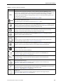
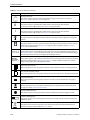
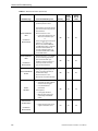
Symbols and Markings
Table 1-1. Ventilator Symbols
Symbols
Descriptions
It is essential to read, understand, and follow these instructions before using the Puritan Bennett 540™
Ventilator (ISO 7000-0434A).
This symbol appears on the ventilator’s back panel, and internal battery; see Table 1-2, item 11.
Type BF applied part (IEC 60417-5333).
A regulatory standard classification for protection against electrical shock for the part of the device that
contacts the patient.
This symbol appears on the ventilator’s back panel; see Table 1-2, item 6.
Direct current, DC (IEC 60417-5031).
This symbol appears on the ventilator’s back panel; see Figure 1-4, item 10. Figure 4-5 on page 4-5
Alternating current, AC (IEC 60417-5032).
This symbol appears on the ventilator’s back panel and keyboard; see Figure 1-4, item 9, and
Figure 2-3 on page 2-5, item 10.
Internal Battery.
This symbol appears on the ventilator’s keyboard; see Figure 2-3 on page 2-5, item 10.
Insulation class II equipment (IEC 60417-5172).
A regulatory standard classification for protection against electric shock. Class II equipment relies on
double insulation rather than protective earthing.
This symbol appears on the ventilator’s back panel; see Table 1-2, item 6.
1-10
Puritan Bennett 540™ Ventilator User’s Manual
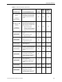
Symbols and Markings
Table 1-1. Ventilator Symbols (Continued)
Symbols
Descriptions
Index of Protection rating for the ventilator’s enclosure, defined in IEC 60529 (BSEN60529:1991).
IP31
The first digit, 3, indicates protection against the intrusion of small foreign bodies (including fingers, tools,
wires, etc. with a diameter greater than 2.5 mm) into the ventilator. The second digit, 1, indicates
protection against water dripping or falling vertically, as well as an environment featuring water vapor
condensation and/or light rain.
This rating appears on the ventilator’s back panel; see Table 1-2, item 6.
CSA – Canadian Standards Association.
This symbol appears on the ventilator’s back panel; see Table 1-2, item 6.
This symbol appears on the ventilator’s front panel UP/UNFREEZE key; see Figure 2-3 on page 2-5, item 6.
This key is used to: move the LCD display’s cursor upwards, line-by-line; increase the value of displayed
and selected parameter settings; restart (“unfreeze”) waveforms tracing.
This symbol appears on the ventilator’s front panel DOWN/FREEZE key; see Figure 2-3 on page 2-5, item 5.
This key is used to: move the LCD display’s cursor downwards, line-by-line; decrease the value of
displayed and selected parameter settings; stop (“freeze”) waveforms tracing.
This symbol appears on the ventilator’s front panel ENTER key; see Figure 2-3 on page 2-5, item 4.
This key is used to confirm command actions.
This symbol appears on the ventilator’s front panel ALARM CONTROL key; see Figure 2-3 on page 2-5,
item 3. (See my notes, to the left and below, in red).
This key is used to: cancel the audible portion of alarms for 60 seconds at a time; cancel an alarm.
For more information, refer to section 3, “Alarms and Troubleshooting.”
This symbol appears on the ventilator’s front panel MENU key; see Figure 2-3 on page 2-5, item 7.
This key is used to access the ventilator’s menus via the ventilator’s front panel LCD display.
This symbol (IEC 60417– 5009). appears on the ventilator’s front panel VENTILATION ON/OFF button; see
Figure 2-3 on page 2-5, item 8.
This key is used to Start and Stop ventilation.
Air outlet towards patient.
This symbol appears on the front right of the ventilator, adjacent to the TO PATIENT port;
see Figure 1-3, item 2, and Figure 4-9 on page 4-9.
Air return from patient (double-limb option).
This symbol appears on the front-left of the ventilator, adjacent to the From Patient port;
see Figure 1-2, item 5.
Patient proximal pressure port.
This symbol appears on the front right of the ventilator, adjacent to the From Patient port;
see Figure 1-1, item 4, and Figure 4-9 on page 4-9.
Exhalation valve pilot port.
This symbol appears on the front right of the ventilator, adjacent to the TO PATIENT port indicating the
connection of the tubing between the patient circuit exhalation valve;
see Figure 1-1, item 4, and Figure 4-9 on page 4-9.
Oxygen inlet.
This marking appears on the back panel of the ventilator, adjacent to the oxygen inlet port;
see Figure 1-4, item 3, and Figure 4-14 on page 4-14.
Puritan Bennett 540™ Ventilator User’s Manual
1-11
Safety Information
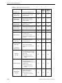
Table 1-1. Ventilator Symbols (Continued)
Symbols
Descriptions
Nurse Call connector.
This symbol appears on the back panel of the ventilator, adjacent to the nurse call connector;
see Figure 1-4, item 3, and Figure 4-18 on page 4-18.
O
I
Switch in “Off” position (IEC 60417-5008).
This symbol appears on the I/O (power on/off ) switch on the back panel of the ventilator
to indicate the switch’s “Off” position. See Figure 2-2 on page 2-4, item 2.
Switch in “On” position (IEC 60417-5007).
This symbol appears on the I/O (power on/off ) switch on the back panel of the ventilator
to indicate the switch’s “On” position. See Figure 2-2 on page 2-4, item 2.
Software Lock Enabled.
This symbol appears on the upper-left of the ventilator’s LCD display when the keyboard Locking Key is
enabled.
Internal Battery.
This symbol appears on the top-center of ventilator’s LCD display to indicate that the ventilator is being
powered by its internal battery. See Figure 2-4 on page 2-6, item 1 and refer to chapter 6, “Internal
Battery”, for more information.
Pressure rise times (inspiratory phase) parameter.
These symbols appear on the ventilation mode menu screens. For more information, refer to chapter 3,
“Operating Parameters”. In pressure ventilation modes, you can select one of four rise times with setting 1
representing the fastest rise time and setting 4 representing the slowest.
Flow shape (“flow distribution shape”, inspiratory phase) parameter.
These symbols appear on the ventilation mode menu screens; selectable for Vol A/C mode only. For more
information, refer to chapter 3, “Operating Parameters”. In volume ventilation modes you can select
between Square (SQ) or Descending (D) flow patterns.
Selected line (filled square).
When making menu choices, this graphic indicates the line on which the cursor is currently positioned.
Non-selected line (empty square).
When making menu choices, this graphic indicates a line on which the cursor is currently not positioned.
Locked parameter line.
When making menu choices, this graphic indicates a line that cannot be selected (the Locking Key is
enabled).
Active parameter line.
When making menu choices, this graphic indicates that the current parameter is selected and can be
changed. See chapter 5, “Operating Procedures”.
Inspiratory Effort Detected.
This symbol appears in the front panel display’s Status window when the patient triggers a breath.
Parameter adjustment bar.
This graphic shows the current setting for parameters such as display contrast and alarm volume in the
Preferences menu.
WEEE (Waste Electrical and Electronic Equipment).
This symbol means that this product must not be disposed of with household waste. Observe local
ordinances for proper disposal. Refer to Table 1-2, item 6.
1-12
Puritan Bennett 540™ Ventilator User’s Manual
Labels / Identification and Instruction Information
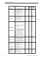
Table 1-1. Ventilator Symbols (Continued)
Symbols
Descriptions
Year of Manufacture.
Manufacturer.
Audio Paused.
This symbol means the sounding of audible alarms is currently disabled. For more information, refer to
section 3.4, “Silencing the Audible Portion of Alarms”.
Alarm Paused (reset/cancelled).
This symbol means one or more alarms have been paused, or reset/cancelled. For more information, refer
to section 3.5, “Resetting/Pausing Alarms”.
Single patient use only (ISO 7000-1051).
This symbol means that the labeled device is for use by a single patient only. Refer to Table 1-2, item 5.
Freeze Waveforms.
This symbol means the tracing of patient pressure and flow waveforms is currently paused or “frozen.”
For more information, refer to section 4.3, “Waveform Display”.
Follow instructions for use (ISO 7000-1641).
This symbol directs the user to observe and adhere to the instructions contained in the product’s
user manuals.
USB port.
This symbol indicates a communications port for interfacing via a USB connector.
See Figure 2-2, item 10. Not currently used.
PC connector.
This symbol indicates a port that can be used by authorized Puritan Bennett service personnel for
software maintenance. See Figure 2-2, item 7.
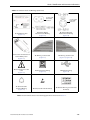
1.5
Labels / Identification and Instruction Information
Various labels or specific markings are affixed to the ventilator that describe precautions to be taken for the
correct use of the ventilator and contribute to the traceability of the product. Refer to Table 1-2 and the figures on
the following pages for illustrations of these labels and markings and their locations on the ventilator. Use the
item numbers in the following tables to locate the labels in Figure 1-1 through Figure 1-5.
Puritan Bennett 540™ Ventilator User’s Manual
1-13
Safety Information
Table 1-2. Ventilator Labels and Markings
1. Alarms Test Label (Figure 1-1, Figure 1-4)
2. Patient Gas Inlet Label
(Figure 1-1, Figure 1-5)
3. Oxygen Inlet Marking
and Label
(Figure 1-4)
4. Exhalation Valve and Patient Pressure
Connection Label
(Figure 1-1, Figure 1-3,
Figure 1-5)
5. Exhalation Limb
Connection of Patient Circuit –
Single Use Exhalation Block
Label
(Figure 1-1, Figure 1-2,
Figure 1-5)
6. Air Inlet Label
(Figure 1-4)
7. Exhaled Gas Outlet Label
(Figure 1-2, Figure 1-4)
1-14
Puritan Bennett 540™ Ventilator User’s Manual
Labels / Identification and Instruction Information
Table 1-2. Ventilator Labels and Markings (Continued)
Location of AC
Power Cable
Connector
Location of DC
Power Cable
Connector
8. Identification Label
(Figure 1-5)
9. AC Power (Mains)
Cable Connector Marking
(Figure 1-4)
10. External DC Power
Cable Connector Marking
(Figure 1-4)
11. Direction of Installation of
Internal Battery Label
(Figure 1-5)
12. Warning - Caution Label
(Figure 1-3)
13. Warning - Caution Label
(Figure 1-2, Figure 1-4)
14. See Instructions For Use
Label
(Figure 1-5)
15. PC Connection marking
(Figure 1-4)
16. USB Port marking
(Figure 1-4)
17. Nurse Call Cable
Connector Marking
(Figure 1-4)
18. ESD (Located inside the Device)
19. AC Mains Warning (Located Inside
the Device)
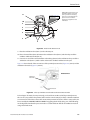
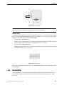
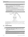
Note: The item number callouts in the following figures refer to those listed in Table 1-2.
Puritan Bennett 540™ Ventilator User’s Manual
1-15
Safety Information
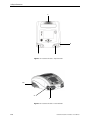
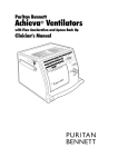
1
2
5
4
Figure 1-1. Locations of Labels – Top-Front View
13
7
5
Figure 1-2. Locations of Labels – Front-Left View
1-16
Puritan Bennett 540™ Ventilator User’s Manual
Labels / Identification and Instruction Information
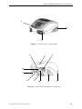
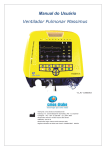
4
12
2
Figure 1-3. Location of Labels – Front-Right View
1
16
9
15
6
3
17
10
13
7
Figure 1-4. Location of Labels and Markings – Back-Left View
Puritan Bennett 540™ Ventilator User’s Manual
1-17
Safety Information
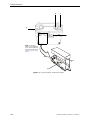
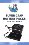
4
2
5
8
NOTE: To view labels
(items 11 and 14), Battery
Cover and Internal Battery
must be removed. Refer to
section 6.6, “Replacing the
Battery.”.
14
11
Figure 1-5. Location of Labels – Bottom-Front View
1-18
Puritan Bennett 540™ Ventilator User’s Manual
2 Ventilator Overview
2.1
Indications for Use
The Puritan Bennett 540™ Ventilator is indicated for the continuous or intermittent mechanical
ventilatory support of patients weighing at least 11lb (5 kg) who require mechanical ventilation. The
ventilator is a restricted medical device intended for use by qualified, trained personnel under the
direction of a physician. It is essential to read, understand, and follow these instructions before using
the Puritan Bennett 540™ Ventilator.
Target Patients
Specifically, the ventilator is applicable for adult and pediatric patients who require the following
general types of ventilatory support, as prescribed by an attending physician:
• Positive Pressure ventilation
• Assist/Control, SIMV, or CPAP modes of ventilation
• Breath types including Volume Control, Pressure Control, and Pressure Support
Target Environments
The ventilator is suitable for use in institutional, home, and portable settings. It is not intended for use
as an emergency transport ventilator.
Target Operators
The ventilator may be operated by:
•
•
•
•
•
Respiratory therapists
Physicians
Nurses
Home care providers
Patient and patient’s families
For more details on the knowledge and skill requirements for operating the Puritan Bennett 540™
Ventilator Ventilator, refer to Appendix A, “Patient/Caregiver Checklist” in the Clinician's Manual.
WARNING
Federal law restricts this device to sale by or on the order of a licensed physician.
2.2
Contraindications
This ventilator is not for use with anesthetic gases, and is not intended for use as an emergency
transport ventilator.
Puritan Bennett 540™ Ventilator User’s Manual
2-1
Ventilator Overview
2.3
Operational Use
The Puritan Bennett 540™ Ventilator uses a micro-turbine and the patient circuit with integral
exhalation valve to provide ventilatory support to patients. Clinicians may use a variety of interfaces
to connect patients to the ventilator: nasal or full face masks; endotracheal or tracheotomy tubes.
User-selectable ventilation modes are:
•
•
•
•
•
•
Assisted Controlled Volume (VOLUME A/C)
Assisted Controlled Pressure (PRESSURE A/C)
Synchronous Intermittent Mandatory Ventilation Volume (V SIMV)
Synchronous Intermittent Mandatory Ventilation Pressure (P SIMV)
Continuous Positive Airway Pressure (CPAP)
Pressure Support Ventilation (PSV)
Safety Net
Incorporated in the ventilator design is an alarm system that continuously monitors both patient and
machine for signs of specific errors or faults that could lead to an unsafe condition. Should any of
these errors or faults be detected, the alarm system announces the specific alarm condition both
audibly and visually. The machine-related alarm conditions are factory set, whereas the patientrelated alarm conditions are defined by alarm-threshold values selected by an operator (a clinician
or a caregiver). For more information, refer to chapter 3, “Alarms and Troubleshooting.”
Settings
A software key, known as the “Locking Key,” restricts access to ventilation parameter settings and
ventilation mode changes in order to distinguish between “clinician” usage and “patient” usage.
Oxygen Enrichment
Oxygen may be supplied from an external, low pressure source, but the oxygen flow must be limited
to 15 lpm at 7.25 psi (50 kPa). The ventilator automatically compensates for the extra flow created by
the external oxygen supply (refer to chapter 4, “Installation and Assembly.”)
Breathing Circuit
The ventilator can be used with a single or double limb patient circuit. If exhaled volume monitoring is
required (such as ventilator dependant patients), use the double-limb circuit for exhaled tidal volume
or minutes volume monitoring. For more information, refer to section 4.4, “Patient Circuit,” on page 46.
Note: It is highly recommended that users always possess an additional breathing circuit and valve while using
the Puritan Bennett 540™ Ventilator.
2.4
Device Classification
The ventilators IEC 60601-1classification is as follows:
•
•
•
•
•
•
2-2
Protection/Insulation class (electric shock): Class II
Protection index of enclosure: IP31
Medical device directive classification: II B
Degree of protection against risk of electric shock: BF
Power: External (AC – mains, or DC – cigarette lighter) or internal (DC – battery)
Operation mode: Continuous operation
Puritan Bennett 540™ Ventilator User’s Manual
Front Panel
For additional information, refer to section A, “Specifications.”
2.5
Front Panel
1
2
3
8
7
5
4
6
1
LCD Display – Displays information about the ventilator
including patient hours and software version, ventilation
modes and settings, and monitored and calculated
patient data and waveforms. The display also allows the
user to view and, using the Control Panel, adjust the
ventilator’s operating and alarm configuration settings.
2
Control Panel – Features the controls for setting up and
operating the ventilator, and LEDs to indicate the
ventilator's power source, ventilation On/Off status, and
alarm priority level. Control functions include turning the
ventilation on and off, configuring ventilation modes,
silencing and canceling alarms, and setting device and
alarm parameters.
5
6
Exhalation Valve Port – Nipple for providing
piloting pressure to the exhalation valve. Controls
the open-closed position of the exhalation valve.
Lateral and Front Openings – Vents that allow for
air circulation to cool the ventilator’s internal
components. In addition, these openings function as
sound ports for audible alarms.
WARNING
Do not cover or obstruct these openings.
3
Patient Connection Port – Provides an outlet for the air
to be delivered to the patient via the patient circuit.
7
4
Patient Pressure Monitoring Port – Nipple for
monitoring proximal patient pressure.
8
From Patient Port -Exhaled volume measurements
are taken from this port, through which a portion of
the exhaled gas is diverted to the exhalation flow
sensor. VTE is calculated from this flow
measurement.a
Exhaled Gas Outlet– Exhalation Valve connects
here.
a. If exhaled volume monitoring is required, use the double-limb circuit for exhaled tidal volume or minutes volume monitoring.
Figure 2-1. Front Panel
Puritan Bennett 540™ Ventilator User’s Manual
2-3
Ventilator Overview
2.6
Back Panel
1
2
3
4
11
10
9
7
8
1
Ergonomic carrying handle.
2
On/Off (I/O) switch with protective cover:
Device powered on in position I; device
switched off in position 0.
3
AC power (“Mains”) cable connector.
4
AC power (“Mains”) cable holding system:
Prevents accidental disconnection of the
AC power cable.
5
Access cover for the internal battery.
6
DC power cable connector with key.
7
8
9
10
11
6
5
PC Cable Connector:
USB mini-B connector used for Puritan Bennett
Ventilator Test Software.
O2 Inlet Port:
Connects the ventilator to a low pressure oxygen
source via an adaptor connected to the O2 Inlet
(refer to section 4.8, “Oxygen,” on page 4-13).
Nurse Call Output Connector:
Used to connect the ventilator to the nurse call
system. Refer to section 4.10, “Mounting the
Ventilator on the Utility Cart,” on page 4-17.
USB Key connection:
USB functionality to allow for system upgrades.
Not currently used.
Air Inlet Filter:
Filters air as it enters the ventilator.
Figure 2-2. Back Panel
2-4
Puritan Bennett 540™ Ventilator User’s Manual
Control Panel
2.7
Control Panel
1
2
10
3
9
4
5
8
6
7
1
Display screen:
6
2
Alarm indicators:
7
Red indicator:
High priority (HP) alarm activated.
Yellow indicator:
3
•
4
•
5
Moves the cursor up and increases
parameter values.
During ventilation reactivates waveform
tracing in the Waveform menu.
ENTER key:
•
•
8
Access to a setting value and validation of
the modification of this setting.
Access to a sub-menu.
VENTILATION ON/OFF button:
•
•
Press once to silence an audible alarm for
60 seconds.
Press twice to halt visual and audible alarms.
If alarm is remedied, the alarm is cancelled
(other than the high pressure alarm).
UP/UNFREEZE Key:
•
MENU key:
Medium priority (MP) alarm
activated
ALARM CONTROL key:
•
Moves the cursor down and decreases parameter values.
During ventilation, freezes displayed waveform in the
Waveform menu.
Changes the displayed menu. From the Ventilation menu
screen, press this key to display the Alarm menu screen.
•
•
DOWN/FREEZE key:
•
•
Display of modes, ventilation settings, patient
data and waveforms, configuration of the
ventilator and alarm management.
9
Press briefly and release to start ventilation.
Press for three (3) seconds to stop ventilation.
Ventilation status indicator:
•
•
Blue indicator illuminated: device is powered on and
ventilation is off (on standby).
Blue indicator off: ventilation is on.
10 Electrical power source indicators:
•
•
•
•
AC POWER indicator lit: AC power source connected.
DC POWER indicator lit: DC power source connected.
INTERNAL BAT indicator lit continuously: Ventilator
powered by internal battery (no external power source
connected.)
INTERNAL BAT indicator flashing: battery charging.
Figure 2-3. Control Panel
Puritan Bennett 540™ Ventilator User’s Manual
2-5
Ventilator Overview
2.8
Ventilation Menu
1
Ventilation menu with ventilation on
standby.
2
5
3
6
4
1
Ventilation menu during ventilation.
2
5
6
3
4
1
General information line:
Displays the current ventilation
mode, along with the
following:
•
•
•
4
2
Displays pressure generation
during ventilation.
3
Displays the specific ventilation
parameter values for the currently
selected ventilation mode.
Battery
symbol if the
device is powered by the
internal battery.
Audio paused
symbol if
an alarm is currently
inhibited.
Alarm paused
symbol if
an alarm has been canceled
manually and the cause of
the alarm remains.
Bargraph:
Ventilation settings:
Preference menu access line:
Highlight this line and press the
ENTER
key to display the
Preference menu.
Refer to chapter 3, “Operating
Parameters” for more information.
5
Status/monitored data window:
•
•
•
6
Alarm conditions window:
•
Ventilation stopped (Standby):
displays the message, “PRESS
TO START VENTILATION.”
Ventilation on: parameters are
monitored and displayed.
The Inspiratory Effort Detected
symbol
appears adjacent to
the monitored I:E ratio when
the patient actively triggers a
breath.
For Active alarms, scrolls
through active alarm
messages in flashing reverse
video.
• For Inactive alarms, displays
the last alarm along with its
trigger date and end-of-event
time.
Refer to chapter 3, “Alarms and
Troubleshooting” for details.
Figure 2-4. Ventilation Menu Display
2-6
Puritan Bennett 540™ Ventilator User’s Manual
Alarm Menu
2.9
Alarm Menu
1
4
Alarm menu with ventilation on standby.
2
5
3
1
4
Alarm menu when not in standby.
2
5
3
1
Title line:
•
•
•
4
2
Displays ventilation mode and
the following symbols:
•
•
•
Ventilation stopped (Standby):
displays the message, “PRESS
TO START VENTILATION.”
Ventilation on: parameters are
monitored and displayed.
The Inspiratory Effort
Detected symbol
appears
adjacent to the monitored I:E
ratio when the patient actively
triggers a breath.
3
Displays the specific alarm
parameter values for the
currently selected
ventilation mode, which are:
Battery if the ventilator
is powered by the internal
battery.
Audio paused
if an
alarm is currently inhibited.
Alarm paused
if an
alarm has been canceled
manually and the cause of
the alarm remains.
Status/monitored data window:
Alarm settings:
•
•
5
Low and High alarm
threshold settings, and
Current monitored
patient readings, or
hyphen (-) when
ventilation is in standby.
Access line to Alarm Log menu.
Highlight this line and press the
ENTER
key to display the
Alarm Log menu.
Refer to manual section 3.3, “Alarm
Logs Menu,” on page 3-3.
Alarm message window:
•
For Active alarms, scrolls
through active alarm
messages in flashing
reverse video.
• For Inactive alarms,
displays the last alarm
along with its trigger
date and end-of-event
time.
Refer to chapter 3, “Alarms
and Troubleshooting” for
more information.
Figure 2-5. Alarm Menu
Puritan Bennett 540™ Ventilator User’s Manual
2-7
Ventilator Overview
2.10 Waveforms Menu
The display of waveforms (Figure 2-6) is optional and can be selected in the using the Menu
key
(refer to chapter 4, “Monitored Parameters.”). The Waveform menu is only accessible when ventilation
is active.
1
2
1
Title line:
Displays ventilation mode and the
following symbols:
•
•
•
•
Battery if the ventilator is
powered by the internal
battery.
Audio paused if an alarm
is currently inhibited.
Alarm paused if an alarm
has been canceled
manually and the cause of
the alarm remains.
Freeze Waveforms
if the tracing of patient
waveforms has been halted
during ventilation.
2
3
Graphic zone:
Displays the patient’s
pressure and flow
waveforms as a function
of time.
3
Numeric zone:
Displays monitored data.
Figure 2-6. Waveforms Menu
2.11 If Ventilator Failure Occurs
If a problem with the ventilator is suspected, FIRST CHECK THAT THE PATIENT IS NOT IN DANGER. If
necessary, remove the patient from the ventilator and provide an alternate means of ventilation.
Keep in mind that troubleshooting information is available in this manual to assist you in the event of
a problem. Refer to chapter 3, “Alarms and Troubleshooting”.
If you cannot determine the cause of a problem, contact your equipment supplier or Puritan Bennett.
Puritan Bennett Technical Services (USA):
1-800-255-6774
2-8
Puritan Bennett 540™ Ventilator User’s Manual
3 Alarms and Troubleshooting
WARNING
Setting Alarm limits to extreme values can cause the ventilator alarms to malfunction.
The alarms or faults generated by your Puritan Bennett 540™ Ventilator are classified into
two categories:
• Ventilation (or utilization) alarms
• Technical faults
Some of the ventilator alarms are adjustable, depending on ventilation modes (refer to
chapter 3, “Operating Parameters”). Automatic, unadjustable alarms also exist to create a safety net
for safe patient ventilation.
Alarms indicate events likely to affect the ventilation in the short term and necessitate rapid
intervention (refer to section 3.8, “Troubleshooting,” on page 3-14).
Technical faults do not directly affect machine operation. Therefore, the user is not alerted to technical
faults. Only authorized and trained technicians may consult the maintenance menu (refer to the
Puritan Bennett 540™ Service Manual).
Note:
Default alarm setting preferences should be entered prior to using the ventilator.
3.1
Alarm Level of Priority
The alarm hierarchy for signaling the level of alarm criticality is listed below.
• Very High Priority (VHP): Immediate critical situation; ventilation is impossible:
Continuous Sound Signaling / With or Without Continuous Red LED Illumination / With or
Without Message / With or Without Display Lighting (it is possible for an alarm condition to
occur that may not have both a message and lighting).
• High Priority (HP): Critical situation in the short term; ventilation is potentially
compromised:
High Frequency Sound Signaling / Flashing Red LED Illumination / With Message / With
Display Lighting
• Medium Priority (MP): Critical situation in the long term; ventilation is not affected in the
short term:
Medium Frequency Sound Signaling / Flashing Yellow LED Illumination / With Message / With
Display Lighting
Note:
There are currently no Low Priority (LP) Alarms.
Puritan Bennett 540™ Ventilator User’s Manual
3-1
Alarms and Troubleshooting
Note:
If there is no corrective action and if the audible alarm is not inhibited (Audio Paused) or reset (Alarm Reset)
within 60 seconds, High Priority alarms will sound at the maximum level of 85 dB(A).
3.2
Alarm Display
During operation, when an alarm is activated:
• One of the red or yellow alarm indicators to the left of the ALARM CONTROL
key
illuminates and flashes.
• An alarm tone sounds.
• A message is displayed and flashes in reverse video at the bottom of the Ventilation Menu or
Alarm Menu.
ALARM INDICATORS
VENTILATION MENU
ALARM MENU
ALARM MESSAGES
Figure 3-1. Alarm Displays
Note:
There are currently no Low Priority (LP) Alarms.
When an alarm is triggered, if the current menu displayed is not the Ventilation parameters or Alarm
menu, the display automatically switches to one of these menus to display the alarm message.
3-2
Puritan Bennett 540™ Ventilator User’s Manual
Alarm Logs Menu
In the event several alarms are activated at the same time, the highest priority audible and visual
alarm is highlighted; however, all active messages are displayed, in the sequence in which they
occurred.
3.3
Alarm Logs Menu
All alarms are recorded in the internal memory of the ventilator at the time they are activated.
The Alarm Logs menu is used to display the last eight (8) alarms activated, along with their date and
time of activation.
To access the Alarm Logs menu, do the following:
1. Press the MENU
displayed).
key to access the alarm setting menu (if this is not the menu currently
2. Press the DOWN
key several times or press until the cursor is on the “Alarm Logs” line at the
bottom of the page. The display appears as follows:
3. Press the ENTER
key. The Alarm Logs screen is displayed.
Note:
When no alarm has been activated, “NO DATA” is displayed on the screen (see graphic below).
Puritan Bennett 540™ Ventilator User’s Manual
3-3
Alarms and Troubleshooting
For more information on the “Reactivate Paused Alarm” line, refer to section 3.6, “Re-activating
Alarms,” on page 3-6.
To dismiss the Alarm Logs screen manually:
Press the ENTER
key when the cursor is on the “Back” line.
The Alarm Logs screen is dismissed automatically:
• After 15 seconds if no keyboard action is detected
• When a High Priority alarm is triggered
Note:
Only qualified service personnel may access all alarms and events recorded by the ventilator. Qualified personnel
should refer to the Puritan Bennett 540™ Service Manual for further information.
3.4
Silencing the Audible Portion of Alarms
You may silence the audible portion of alarms for 60 seconds at a time. This is referred to as the Audio
Paused function.
To silence the audible portion of activated alarms:
Press the ALARM CONTROL
key.
• The audible portion of all activated alarms is paused.
• The visual portions (light indicator and message) of activated alarms remain visible.
• The Audio Paused symbol
is displayed at the top right of the screen while the audio
pause function is active.
If several alarms are activated at the same time, pressing the ALARM CONTROL
current alarms.
3-4
key affects all
Puritan Bennett 540™ Ventilator User’s Manual
Resetting/Pausing Alarms
The audible portion of activated alarms is automatically reactivated:
• After 60 seconds, if the cause(s) of the alarm(s) persist(s)
• Whenever a new alarm is activated
Note:
If a key is stuck or held down for 45 seconds a keypad alarm will occur.
3.5
Resetting/Pausing Alarms
WARNING
• Alarm volume should be adjusted with respect to the ventilator’s operating environment and so that
the patient's caretakers can hear the alarms. The audible alarm vents located at the front of the device
should never be obstructed. The alarm can be paused with the Alarm Pause function by pressing the
ALARM CONTROL key twice once the alarm has been declared.
•
When an alarm condition is triggered, or there is evidence of a patient-ventilator fault or problem,
examine the patient first before examining the ventilator.
Some alarms are not automatically cancelled when the condition causing the alarm ceases; these can
be paused manually even if the cause(s) of their activation remain(s).
To manually pause an alarm, proceed as follows:
Press the ALARM CONTROL
key twice.
• The alarm is paused: the audible portion, light indicator, and message are all halted (for the
alarms which can be paused manually).
• The Alarm Paused
symbol is displayed at the top right of the Ventilation,
Alarms, and Waveforms screens. See the sample screen, below.
When no other alarms are currently activated, the last alarm cancelled is displayed continuously in the
alarm message window in the Alarms menu, along with the date and time of its activation (as shown
above).
The High Pressure alarm must be manually reset. Refer to section 3.7, “Overview of Alarms,” on page 37.
To manually reset the High Pressure Alarm, proceed as follows:
Press the ALARM CONTROL
key twice.
• The visual alarms will be reset.
Puritan Bennett 540™ Ventilator User’s Manual
3-5
Alarms and Troubleshooting
3.6
Re-activating Alarms
Alarms that have been paused and whose activation conditions continue to exist can be reactivated.
To reactivate alarms, proceed as follows:
1. Press the MENU
displayed.
key to access the Alarm Setting menu, if this is not the menu currently
2. Press the DOWN
key to position the cursor on the “Alarm Logs” line, if this is not already
the case. The following graphic shows an example of the resulting display.
3. Press the ENTER
key, to confirm access to the “Alarm Logs” menu.
4. Press the UP
key to position the cursor on the “Reactivate Paused Alarm” line. The following
graphic shows the resulting display.
5. Press the ENTER
•
•
•
•
•
•
3-6
key for at least three (3) seconds. The following events occur:
A “beep” sounds.
An audible alarm sounds.
An alarm indicator illuminates.
The messages of all active alarms are displayed in a loop in the Ventilation and Alarm menus.
The Audio Paused symbol
disappears (if it was displayed).
The Alarm Paused symbol
disappears.
Puritan Bennett 540™ Ventilator User’s Manual
Overview of Alarms
3.7
Overview of Alarms
Note:
The message: “*IF PERSISTS REPLACE VENT” will occur only if the alarm condition continues for longer than 30
seconds.
Table 3-1. Overview of Alarms
Alarm Message
Cause/Ventilator Response
AC POWER
DISCONNECTION
Cut-off of the AC (mains) power
supply.
Alarm activation occurs:
• After 5 seconds if ventilation
is stopped
• At the start of a ventilation
cycle when ventilation is in
progress.
Consequence: switch over to
external DC power supply if
present, otherwise to the
internal battery.
APNEA
No inspiratory trigger detected by
the ventilator after the apnea time
set in PSV/CPAP, P SIMV and V SIMV
modes.
Priority
Audio
Paused
Avail.
Alarm
Paused
Avail.
MP
Yes
Yes
MP
Yes
Yes – except
for CPAP
MP
Yes
No
MP
Yes
No
Automatically clears itself after two
successive patient breaths.
BATT FAULT1
CALL SERVICE
BATT FAULT2
CALL SERVICE
Ventilator has detected an
internal battery fault.
Consequence: the internal
battery is disabled from use.
No internal battery detected.
BATT FAULT3
CALL SERVICE
The internal battery is not
recognized as a
Puritan Bennett battery.
MP
Yes
No
BATT FAULT4
REPLACE VENT
Internal battery charging failure.
Consequence: charging of the
internal battery impossible.
MP
Yes
Yes
Battery temperature out of
tolerance.
Consequence: battery charging
stops.
MP
Yes
Yes
Failure of one calibration point
of the internal exhaled flow
sensor.
Consequence: failed calibration
point is replaced by the default
point.
MP
Yes
Yes
BATT TEMP FAULT*
*IF PERSISTS
REPLACE VENT
CAL FAULT
SEE USER MNL
Puritan Bennett 540™ Ventilator User’s Manual
3-7
Alarms and Troubleshooting
Table 3-1. Overview of Alarms (Continued)
Priority
Audio
Paused
Avail.
Alarm
Paused
Avail.
MP
Yes
No
MP
Yes
No
CHECK/CHANGE EXH
VALVE2
Abnormally high expired flow
during the inspiratory phase of
three consecutive breaths (in
double-limb setup).
Alarm activation occurs:
After three consecutive breaths.
MP
Yes
No
CHECK
Alarm activation occurs:
• Systematically after software
versions have changed.
• Loss of memorized
parameters
Consequence:
• Locking Key disabled
• Out-of-range settings are
replaced by their default
values
MP
Yes
Yes
HP
Yes
Yes
Alarm Message
Cause/Ventilator Response
1. Loss of signal from the
proximal pressure sensor
CHECK PROXIMAL
LINE1
*IF PERSISTS
REPLACE VENT
CHECK PROXIMAL
LINE2
*IF PERSISTS
REPLACE VENT
SETTINGS
CHK EXH VALV
RESTART VENT*
Consequence: switch to internal
pressure sensor for the pressure
measurement.
Alarm activation occurs:
• In the event of signal loss (1):
After one ventilation cycle
or
In the event of signal loss(2) and
after the 17th breath cycle:
After 17 seconds for PRES A/C
and VOL A/C modes, or after the
maximum time between 17
seconds and Apnea Time + 4
seconds for CPAP/PSV/ P SIMV,
and V SIMV modes
Proximal pressure < 0.6 cmH2O
for 100 ms during inspiration
phase of 2nd breath cycle
Ventilator response: Switch to
internal pressure sensor for
pressure measurement.
•
Faulty pressure valve sensor
signal at ventilation start.
*IF PERSISTS
REPLACE VENT
3-8
Puritan Bennett 540™ Ventilator User’s Manual
Overview of Alarms
Table 3-1. Overview of Alarms (Continued)
Priority
Audio
Paused
Avail.
Alarm
Paused
Avail.
HP
Yes
No
Measurement and calculation of
tidal volume do not match Vt set
during six consecutive breaths in
VOL inspired and V SIMV modes.
Alarm activation occurs:
• After six consecutive
breaths—once the ventilator
has reached its performance
limits.
HP
Yes
No
DEVICE FAULT1
REPLACE VENT
Faulty internal pressure sensor
signal.
Alarm activation occurs:
• After 15 seconds.
HP
Yes
No
DEVICE FAULT2
REPLACE VENT
Faulty proximal pressure sensor
signal.
Alarm activation occurs:
• After 15 seconds.
MP
Yes
Yes
DEVICE FAULT3
REPLACE VENT
Failure in the 24 V
power supply.
HP
Yes
No
DEVICE FAULT4
REPLACE VENT
Ventilator cooling fan operating
speed not suited to the internal
ambient temperature of the
device.
MP
Yes
Yes
DEVICE FAULT5
REPLACE VENT
Detection of a fault in the
electrical power supply system.
Consequence: the internal
battery capacity is not displayed
beside the battery symbol.
MP
Yes
Yes
DEVICE FAULT6
REPLACE VENT
Turbine speed too high with
high temperature.
Consequence: ventilation stops
immediately and O2 supply
stops.
HP
No
No
DEVICE FAULT7
REPLACE VENT
Detection of a fault in sensor
voltage measurement.
HP
Yes
No
HP
Yes
No
DEVICE FAULT8
REPLACE VENT
Inspiratory flow is constant (+/- 1
lpm) with normal turbine
temperature and speed
conditions. Contact your service
representative for assistance.
Alarm Message
CHECK/CHANGE EXH
VALVE1*
*IF PERSISTS
Cause/Ventilator Response
Inspired tidal volume during
exhalation < 40% of Inspired
Tidal volume and inspired tidal
volume inspired tidal volume >
20mL
REPLACE VENT
CHK VOL/INSP TIME
SETTINGS*
*IF PERSISTS
REPLACE VENT
Puritan Bennett 540™ Ventilator User’s Manual
3-9
Alarms and Troubleshooting
Table 3-1. Overview of Alarms (Continued)
Alarm
Paused
Avail.
VHP
No
No
VHP
No
No
Alarm Message
Cause/Ventilator Response
DEVICE FAULT9
REPLACE VENT
POST RAM Error. RAM
Read/Write does not match
memory setting.
DEVICE FAULT10
REPLACE VENT
POST FLASH Checksum Error.
Startup FLASH computed
checksum does not match
memory setting.
DEVICE FAULT11
REPLACE VENT
POST EEPROM Error. Startup
EEPROM does not match
memory setting.
VHP
No
No
DEVICE FAULT12
REPLACE VENT
POST Reference Voltage Error. 5V
or 10V reference voltage error.
VHP
No
No
DEVICE FAULT13
Software Version Error.
VHP
No
No
EMPTY BATTERY
Internal battery capacity
< 10 min. or 2%.
(battery voltage < 22.5V)
Consequence: ventilation comes
to a halt.
HP
No
No
At least four of the last six
spontaneous breaths are
terminated by time.
MP
Yes
No
Device internal ambient
temperature out of tolerance
range.
MP
Yes
Yes
HIGH EXH
VOLUME
Expired tidal volume greater
than High VTE set during three
consecutive breaths (in double
limb setup).
Alarm activation occurs:
• After three consecutive
breaths.
MP
Yes
No
HIGH INSP VOLUME
Inspired tidal volume greater
than High VTI set during three
consecutive breaths in
PSV/CPAP, PRES A/C, P SIMV, and
V SIMV modes.
Alarm activation occurs:
• After three consecutive
breaths.
HP
Yes
No
HIGH MINUTE
VOLUME
Minute volume higher than High
MinVol set during three
consecutive breaths.
Alarm activation occurs:
• After three consecutive
breaths.
MP
Yes
No
EXHSENS FAULT OR
CRKT LEAK
HIGH DEVICE TEMP
COOL VENT*
*IF PERSISTS
REPLACE VENT
3-10
Priority
Audio
Paused
Avail.
Puritan Bennett 540™ Ventilator User’s Manual
Overview of Alarms
Table 3-1. Overview of Alarms (Continued)
Alarm Message
Cause/Ventilator Response
•
In VOL A/C or V SIMV modes, if
Inspiratory Pressure is higher
than High PIP during three
consecutive cycles.
or
•
In PSV/CPAP, PRES A/C, or P SIMV
modes, if Inspiratory Pressure is
higher than (P Support or P
Control + PEEP) + 5 cmH2O up to
29 cmH2O or + 10 cmH2O over
30 cmH2O during three
consecutive cycles.
or
HIGH PRESSURE
•
In PSV/CPAP mode and P
Support is set to off, if
Inspiratory Pressure is higher
than PEEP + 10cmH2O during
three consecutive cycles.
Alarm activation occurs:
•
After three consecutive
breaths.
Consequence:
•
HIGH RATE
INVERSED I:E
RATIO
KEYPAD FAULT CALL
SERVICE*
*IF PERSISTS
REPLACE VENT
LOW BATTERY
LOW EXH VOLUME
Priority
Audio
Paused
Avail.
Alarm
Paused
Avail.
Yes
No
HP
Note:
When
alarm
condition
becomes
false, alarm
priority
indicator
must be
manually
reset by
pressing
the
key.
Switch to exhalation phase.
Rate measured greater than
High Rtot set during three
consecutive breaths.
Alarm activation occurs:
• After three consecutive
breaths.
MP
Yes
No
An Insp Time setting that results
in an inspiratory time greater
than the exhalation time.
Alarm activation occurs:
• Upon setting parameter
values, such that the Insp
Time value exceeds the limit
described above.
MP
Yes
Yes
Keyboard key held down for
more than 45 seconds.
HP
No
No
Internal battery capacity
< 30 min. or 5%.
HP
Yes
No
Expired tidal volume less than
Low VTE set during three
consecutive breaths (in doublelimb setup).
Alarm activation occurs:
• After three consecutive
breaths.
MP
Yes
No
Puritan Bennett 540™ Ventilator User’s Manual
3-11
Alarms and Troubleshooting
Table 3-1. Overview of Alarms (Continued)
Priority
Audio
Paused
Avail.
Alarm
Paused
Avail.
LOW INSP VOLUME
Inspired tidal volume less than
Low VTI set during three
consecutive breaths in
PSV/CPAP, PRES A/C, P SIMV and
V SIMV modes.
Alarm activation occurs:
• After three consecutive
breaths.
MP
Yes
No
LOW MINUTE
VOLUME
Minute volume lower than Low
Min Vol set during three
consecutive breaths.
Alarm activation occurs:
• After three consecutive
breaths
MP
Yes
No
HP
Yes
No
Occurs when the buzzer battery
is too low to sound an alarm
when ventilating using battery
power. Connecting the
ventilator to AC power for 15
minutes should clear the alarm.
MP
Yes
Yes
Tidal volume measured
negligible during three
consecutive breaths for
PSV/CPAP, PRES A/C and P SIMV
modes.
Alarm activation occurs:
• After three consecutive
breaths.
HP
Yes
No
Cut-off of the external DC power
supply.
Consequence: switch-over to
the internal battery.
MP
Yes
Yes
Alarm Message
LOW PRESSURE
DISCONNECT*
*IF PERSISTS
REPLACE VENT
Cause/Ventilator Response
•
If the flow is greater than
130 lpm during the inspiratory
phase.
or
•
In VOL A/C and V SIMV modes, if
patient pressure is lower than
Low PIP.
or
•
In PSV/CPAP, PRES A/C modes
and P SIMV if patient pressure is
lower than (P Support + PEEP) 20% or (P Control + PEEP) - 20%.
Alarm activation occurs:
If one of these three conditions
remains for more than 15 seconds,
or the maximum time between
15 seconds and Apnea Time + 2
seconds.
LOW SPKR/BATTERY
OCCLUSION CHECK
CIRCUIT*
*IF PERSISTS
REPLACE VENT
ON INTERNAL
BATTERY
(with Periodic
Audible Signal)
3-12
Puritan Bennett 540™ Ventilator User’s Manual
Overview of Alarms
Table 3-1. Overview of Alarms (Continued)
Priority
Audio
Paused
Avail.
Alarm
Paused
Avail.
MP
Yes
Yes
VHP
No
Yes
No activation of Nurse Call when
an alarm is in progress.
MP
Yes
Yes
SOFTWARE VERSION
ERROR
Detection of a wrong software
version.
NA
NA
NA
SPKR FAULT1
REPLACE VENT
Defective operation of the
buzzers.
Consequence: no audible tone
when an alarm is activated.
MP
Yes
No
SPKR FAULT2
REPLACE VENT
Failure detected in the
Very High Priority buzzer.
Consequence: no audible alarm
in case of involuntary stop of the
ventilation.
MP
Yes
Yes
SPKR FAULT3
REPLACE VENT
Battery Charge Failure due to
incorrect voltage. Contact your
service representative for
assistance.
HP
Yes
No
SPKR FAULT4
REPLACE VENT
Buzzer Battery Failure. The
Battery Buzzer Voltage is too
low, disabling the buzzer.
Contact your service
representative for assistance.
MP
Yes
Yes
Alarm Message
POWER FAULT
REPLACE VENT
Cause/Ventilator Response
Detection of a fault in the
electrical power supply system.
1. Electrical power supply to the
machine is interrupted with the
I/O switch when ventilation is in
progress
or
POWER SUPPLY LOSS
(no message)
REMOTE ALARM
FAULT
2. Battery fully discharged when
it was the only source of power
to the ventilator.
Consequence: ventilation stops
immediately. Ventilation restarts
immediately when the switch is
pressed in case 1 (above) or after
restoration of the AC or DC
supply in case 2 (above).
Puritan Bennett 540™ Ventilator User’s Manual
3-13
Alarms and Troubleshooting
3.8
Troubleshooting
Caution
• This manual tells you how to respond to ventilator alarms, but it does NOT tell you how to respond to the
patient.
•
To ensure proper servicing of the ventilator and reduce the possibility of physical injury, only qualified
personnel should attempt to service the Puritan Bennett 540™ Ventilator.
3.8.1 Alarms
WARNING
When an alarm condition is triggered, or there is evidence of a patient-ventilator fault or problem,
examine the patient first before examining the ventilator.
Table 3-2 offers a guide to the most likely ventilator alarms, possible reasons for the alarms, and
corrective actions.
WARNING
Except for replacing the internal battery and cleaning the device, do not try to repair or otherwise service
the ventilator yourself, or modify the ventilator, its components, or accessories. Doing so might endanger
the patient, cause damage to the ventilator, and/or void your warranty. Only qualified service personnel
should attempt repair of the ventilator.
Table 3-2. Alarms and Corrective Actions
Alarm Message or
Symptom
AC POWER
DISCONNECTION
3-14
Possible Reason(s) For The Alarm Event
Corrective Action(s)
AC (“mains”) power source cut off.
Cancel the alarm then check the supply
cable and/or the effective availability of a
voltage on the AC power (“mains”) port.
Starting with 12 – 30 VDC external power
supply.
Cancel the alarm.
Current-limiting fuse of the device blown.
Replace the ventilator and call for the
maintenance technician.
Puritan Bennett 540™ Ventilator User’s Manual
Troubleshooting
Table 3-2. Alarms and Corrective Actions (Continued)
Alarm Message or
Symptom
Possible Reason(s) For The Alarm Event
Corrective Action(s)
CAUTION: Ensure that you are operating
the ventilator within the proper
temperature range (refer to Appendix A,
“Specifications”).
Put the device in a warmer environment
(if the ambient temperature is too low) or
in a cooler environment (if the ambient
temperature is too high).
AMBIENT TEMP.
ALERT
Internal ambient temperature of the device
out of the tolerance ranges.
WARNING
In case of operation in a high ambient
temperature, handle the ventilator
with care; some portions of the device
may have high surface temperatures.
WARNING
In the case of high ambient
temperatures, it may take a significant
period of time to cool the internal
temperature of the ventilator to the
proper operating range. To avoid
injury to the patient, ensure that the
air inspired by the patient does not
exceed 106 °F (41 °C). If in doubt,
replace the ventilator.
Defective internal temperature probe or
any other technical anomaly.
Replace the ventilator and call your
customer service representative.
Patient’s breathing effort less than the
Sensitivity control setting.
Under the guidance of a Clinician adjust
the Insp Sens setting that which is
appropriate for the patient.
Patient apnea.
Examine the patient for breathing effort
and stimulate if necessary.
Defective sensors.
Have a qualified technician replace the
defective component(s) and call your
customer service representative.
BATT FAULT1
CALL SERVICE
Battery problem that prevents it from
operating.
Replace the ventilator and call your
customer service representative.
BATT FAULT2
CALL SERVICE
Internal battery missing or not detected.
Replace the ventilator and call your
customer service representative.
BATT FAULT3
CALL SERVICE
Internal battery not recognized as a
Puritan Bennett battery.
Call your customer service representative.
Battery charging impossible.
Do not disconnect the ventilator from the
AC power supply. Ensure that the power
cable is installed according to the
instructions in chapter 4, “Installation and
Assembly”, so that the power cable
cannot be involuntarily disconnected.
In the event the internal battery capacity
is low, use an alternate device to ventilate
the patient.
Call your customer service representative.
AMBIENT TEMP.
ALERT
APNEA
BATT FAULT4
REPLACE VENT
Puritan Bennett 540™ Ventilator User’s Manual
3-15
Alarms and Troubleshooting
Table 3-2. Alarms and Corrective Actions (Continued)
Alarm Message or
Symptom
Possible Reason(s) For The Alarm Event
Battery temperature out of the
tolerance ranges.
BATTERY TEMPERATURE
FAULT
Defective internal temperature probe or
any other technical anomaly inside the
battery.
Corrective Action(s)
CAUTION: Ensure that ventilator is being
used according to the operating
instructions found in Appendix A,
“Specifications”.
If the ambient temperature is too low,
place the device in a warmer
environment.
If the ambient temperature is too high,
place the ventilator in a cooler
environment.
WARNING
In case of operation in a high ambient
temperature, handle the ventilator
with care; some portions of the device
may have high surface temperatures.
Call your customer service representative.
CAUTION: Do not attempt to charge a
defective battery; such a battery cannot
be charged.
Too large a difference between a
calibration point and its tolerance range.
Restart calibration.
Defective expiratory flow sensor.
Have a qualified technician replace the
defective component(s) and call your
customer service representative.
CHECK
EXH. VALVE
RESTART VENT*
Obstruction or abnormal damage of the
exhalation valve.
Clean or replace the exhalation valve
and/or its control tube.
Defective connection or defective
exhalation valve tubing.
Reconnect the valve or replace the
exhalation valve and/or the exhalation
valve pilot pressure tube.
*IF PERSISTS REPLACE
VENT
Defective inspiratory flow sensor.
Have a qualified technician replace the
defective component(s) and call your
customer service representative.
No connection of the proximal pressure
tube when ventilation starts.
Reconnect the proximal pressure line.
Proximal pressure line disconnected or
obstructed.
Reconnect the connection line or
replace it if obstructed.
Defective proximal pressure sensor or
internal leak of the machine.
Have a qualified technician replace the
defective component(s) and call your
customer service representative..
CALIBRATION FAULT
CHECK PROXIMAL LINE1*
*IF PERSISTS
REPLACE VENT
Loss of memorized parameters.
CHECK SETTINGS
CHECK/CHANGE
EXH VALVE1 *
*IF PERSISTS
REPLACE VENT
3-16
Software versions have changed.
Check and adjust the prescribed
parameters, if necessary.
Large leakage detected on the patient
circuit return limb during the inspiratory
phase.
Replace the exhalation valve and/or its
control tube.
Contaminated or defective expiratory flow
sensor.
Have a qualified technician replace the
defective component(s) and call your
customer service representative.
Puritan Bennett 540™ Ventilator User’s Manual
Troubleshooting
Table 3-2. Alarms and Corrective Actions (Continued)
Alarm Message or
Symptom
CHK VOL/INSP
TIMESETTINGS
Possible Reason(s) For The Alarm Event
Corrective Action(s)
Defective inspiratory flow sensor or internal
leak of the machine.
Replace the defective device(s) and have a
qualified technician check them.
DEVICE FAULT1 REPLACE
VENT
Defective internal pressure sensor.
Have a qualified technician replace the
defective component(s) and call your
customer service representative.
DEVICE FAULT2 REPLACE
VENT
Defective proximal pressure sensor or
internal leak of the machine.
Have a qualified technician replace the
defective component(s) and call your
customer service representative.
24 V supply failure.
Replace the ventilator and call your
customer service representative.
*IF PERSISTS
REPLACE VENT
DEVICE FAULT3
REPLACE VENT
DEVICE FAULT4 REPLACE
VENT
Operating speed of the cooling fan not
properly adjusted for the internal ambient
temperature of the device.
Replace the ventilator and call your
customer service representative.
DEVICE FAULT5 REPLACE
VENT
Internal problem in the electrical power
supply.
Replace the ventilator and call your
customer service representative.
DEVICE FAULT6 REPLACE
VENT
Turbine overheated because of blockage
during operation.
Replace the ventilator and call your
customer service representative.
DEVICE FAULT7 REPLACE
VENT
Internal technical problem.
Replace the ventilator and call your
customer service representative.
DEVICE FAULT8 REPLACE
VENT
Inspiratory flow is constant (+/- 1 lpm) with
normal turbine temperature and speed
conditions.
Replace the ventilator and call your
customer service representative.
DEVICE FAULT9 REPLACE
VENT
POST RAM Error. RAM Read/Write does not
match memory setting.
Replace the ventilator and call your
customer service representative.
DEVICE FAULT10
REPLACE VENT
POST FLASH Checksum Error. Startup
FLASH computed checksum does not
match memory setting.
Replace the ventilator and call your
customer service representative.
DEVICE FAULT11
REPLACE VENT
POST EEPROM Error. Startup EEPROM does
not match memory setting.
Replace the ventilator and call your
customer service representative.
DEVICE FAULT12
REPLACE VENT
POST Reference Voltage Error. 5V or 10V
reference voltage error.
Replace the ventilator and call your
customer service representative.
DEVICE FAULT13
REPLACE VENT
Software Version Error
Replace the ventilator and call your
customer service representative.
Internal battery capacity is less than
10 min. (or 2%) —battery operation
overextended.
Reconnect the device to an AC power
outlet, connect it to an external DC power
source, or replace the battery.
Reminder: the internal battery can be
charged only when the ventilator
connected to an AC power supply.
Leak in the patient circuit.
Check and properly connect the patient
circuit connections.
EMPTY BATTERY
EXHSENS FAULT OR
CIRCUIT FAULT
Puritan Bennett 540™ Ventilator User’s Manual
3-17
Alarms and Troubleshooting
Table 3-2. Alarms and Corrective Actions (Continued)
Alarm Message or
Symptom
HIGH EXH VOLUME
HIGH INSP VOLUME
HIGH MINUTE VOLUME
HIGH PRESSURE
3-18
Possible Reason(s) For The Alarm Event
Corrective Action(s)
Adjustment of the High VTE level too low.
Under the guidance of a Clinician modify
the High VTE level.
Inappropriate patient circuit.
Replace the patient circuit.
Expiratory flow sensor not calibrated
properly.
Calibrate the expiratory flow sensor (refer
to section 8.1, “Replacing the Air Inlet
Filter,” on page 8-1).
Defective expiratory flow sensor.
Replace the exhalation block and calibrate
the expiratory flow sensor (see section
8.1, “Replacing the Air Inlet Filter,” on page
8-1). Call your customer service
representative.
Adjustment of the High VTI level too low
(for PSV/CPAP, PRES A/C, PRES SIMV and
VOL SIMV modes).
Under the guidance of a Clinician and
modify the High VTI level.
Adjustment of the pressure level too high
for the volume required (for PSV/CPAP,
PRES A/C, PRES SIMV and VOL SIMV
modes).
Under the guidance of a Clinician and
modify the pressure level.
Leak in the patient circuit.
Check and properly connect the patient
circuit.
Inappropriate patient circuit.
Replace the patient circuit.
Defective flow sensor or internal leak in the
machine.
Have a qualified technician replace the
defective component(s) and call your
customer service representative.
Adjustment of the High Min Vol level
too low.
Under the guidance of a Clinician modify
the High Min Vol level.
Leak in the patient circuit.
Check and properly connect the patient
circuit connections.
Inappropriate patient circuit.
Replace the patient circuit with an
appropriate one.
Defective flow sensor or internal leak of the
machine.
Have a qualified technician replace the
defective component(s) and call your
customer service representative.
Adjustment of High PIP too low (only for
VOL A/C and VOL SIMV modes).
Under the guidance of a Clinician increase
the High PIP threshold.
Airway obstruction.
Check patient’s trachea and clear the
obstruction. If the filter is obstructed,
replace the filter.
Proximal pressure tube or patient circuit
obstructed.
Clean the proximal pressure tube or the
patient circuit or replace them.
Coughing or other high-flow expiratory
efforts.
•
•
Patient inspiratory resistance or
compliance changes.
Have physician determine new ventilator
settings.
Defective internal circuits of the machine or
pressure sensor.
Replace the ventilator and call your
customer service representative.
Silence the alarm, if necessary.
Treat patient’s cough.
Puritan Bennett 540™ Ventilator User’s Manual
Troubleshooting
Table 3-2. Alarms and Corrective Actions (Continued)
Alarm Message or
Symptom
HIGH RATE
Possible Reason(s) For The Alarm Event
Corrective Action(s)
Adjustment of the High Rtot level too low.
Under the guidance of a Clinician readjust High Rtot.
Adjustment of the Insp Sens level too low.
Under the guidance of a Clinician adjust
Insp Sens according to the patient.
Patient’s hyperventilation.
Silence the alarm and call for a medical
team if the symptoms persist.
Defective inspiratory flow sensor.
Have a qualified technician replace the
defective component(s) and call your
customer service representative.
Decrease the adjustment threshold of
Insp Time.
INVERSED
I:E RATIO
Adjusted Insp Time inducing an inspiratory
time higher than the expiratory time.
Pressing a key for more than 45 seconds.
Press and release keys in the normal,
prescribed manner. Do not press keys for
45 seconds or more.
A key on the keyboard is stuck.
Attempt to activate each key. If
unsuccessful in releasing the stuck key(s),
replace the device and call your customer
service representative if the situation
persists.
Internal battery capacity is less than
30 min. (or 5%)—battery operation over
extended.
Immediately connect the ventilator to an
AC power outlet, or connect it to an
external DC power source.
Reminder: the internal battery can be
charged only when the ventilator is
connected to an AC power supply.
Patient circuit obstructed.
Clean, unblock, and/or properly connect
the patient circuit.
Leak in the patient circuit.
Check and properly connect the patient
circuit connections.
Exhalation block missing or disconnected.
Call your customer service representative
or clinician.
KEYPAD FAULT
CALL SERVICE
*IF PERSISTS REPLACE
VENT
LOW BATTERY
WARNING
Ensure the Insp Time setting is
compatible with the physiological
requirements of the patient.
Set the Low VTE alarm limit to OFF.
Adjustment of a Low VTE threshold when
the patient circuit is in a single-limb
configuration.
LOW EXH VOLUME
WARNING
If exhaled volume monitoring is
required, use the double-limb circuit
for exhaled tidal volume or minute
volume monitoring.
Inappropriate patient circuit.
Replace the patient circuit with an
appropriate one.
Expiratory flow sensor not properly
calibrated.
Call your customer service representative
or clinician.
Defective expiratory flow sensor.
Replace the defective component(s) and
Call your customer service representative
or clinician.
Adjustment of the Low VTE level too high.
Under the guidance of a Clinician modify
the Low VTE level.
Puritan Bennett 540™ Ventilator User’s Manual
3-19
Alarms and Troubleshooting
Table 3-2. Alarms and Corrective Actions (Continued)
Alarm Message or
Symptom
LOW INSP VOLUME
LOW MINUTE VOLUME
LOW PRESSURE
DISCONNECT
*IF PERSISTS REPLACE
VENT
Possible Reason(s) For The Alarm Event
Adjustment of the Low VTI level too high
(for PSV/CPAP, PRES A/C, PRES SIMV and
VOL SIMV modes)
Under the guidance of a Clinician modify
the Low VTI level.
Adjustment of the pressure level not
enough to reach the volume required (for
PSV/CPAP, PRES A/C, PRES SIMV and VOL
SIMV modes).
Under the guidance of a Clinician modify
the pressure level.
Patient circuit obstructed or disconnected.
Clean, unblock, and/or reconnect the
patient circuit.
Inappropriate patient circuit.
Replace the patient circuit.
Defective flow sensor or internal leak in the
machine.
Have a qualified technician replace the
defective component(s) and call your
customer service representative.
Adjustment of the Low Min Vol level too
high.
Under the guidance of a Clinician modify
the Low Min Vol level.
Inappropriate patient circuit.
Replace the patient circuit with an
appropriate one.
Patient circuit obstructed or disconnected.
Clean, unblock, and/or properly connect
the patient circuit.
Defective flow sensor or internal leak of the
machine.
Have a qualified technician replace the
defective component(s) and call your
customer service representative.
Adjustment of Low PIP too high.
Under the guidance of a Clinician
decrease the Low PIP threshold.
Leak or loose connection in the patient
circuit.
Check the patient circuit connections to
the ventilator; examine all connections for
leakage and tightness.
Replace the patient circuit if necessary.
Inappropriate patient circuit.
Replace the patient circuit.
Defective internal circuits of the machine or
pressure sensor.
Have a qualified technician replace the
defective component(s) and call your
customer service representative.
Patient circuit obstructed.
Clean, unblock, and/or properly connect
the patient circuit.
12 – 30 VDC power supply cut off when
there is no AC (“mains”) power supply.
Cancel the alarm then check the supply
wiring and/or the effective availability of
voltage on the external source.
Ventilator’s current-limiting fuse blown.
Replace the ventilator and call your
customer service representative.
Internal problem in the electrical power
supply.
Replace the ventilator and call your
customer service representative.
OCCLUSION
CHECK CIRCUIT
*IF PERSISTS
REPLACE VENT
ON INTERNAL BATTERY
POWER FAULT
REPLACE VENT
3-20
Corrective Action(s)
Puritan Bennett 540™ Ventilator User’s Manual
Troubleshooting
Table 3-2. Alarms and Corrective Actions (Continued)
Alarm Message or
Symptom
Possible Reason(s) For The Alarm Event
Electrical power supply cut off by the main
switch when ventilation is in progress.
Press the I/O switch to restore electrical
power to the ventilator and allow
ventilation to continue.
To stop ventilation, press the
VENTILATION ON/OFF key for three
seconds (refer to chapter 5, “Operating
Procedures”).
The internal battery that supplies the
ventilator is entirely discharged.
Immediately connect the ventilator to an
AC power outlet or an external DC power
source; otherwise, use an alternate device
to ventilate the patient.
Nurse Call is disconnected.
Connect the Nurse Call cord to the
ventilator.
Relay control voltage problem.
Call for the maintenance technician and
carefully monitor the patient to detect
possible alarm triggering.
Incorrect software version detected.
Call your customer service representative.
Defective internal buzzers.
Replace the ventilator and call your
customer service representative.
POWER SUPPLY LOSS
(without message)
REMOTE ALARM FAULT
SOFTWARE VERSION
ERROR
Corrective Action(s)
•
•
SPKR FAULT1, SPKR
FAULT2
REPLACE VENT
Internal technical problem that prevents
the very high priority “POWER SUPPLY
LOSS” alarm from triggering.
•
•
SPKR FAULT3
REPLACE VENT
Internal technical problem that prevents
the battery from correctly charging.
SPKR FAULT4
REPLACE VENT
Internal technical problem that prevents
the battery warning buzzer from operating.
Call your customer service
representative.
Connect the ventilator to its AC power
supply. Ensure that the internal battery
is completely charged.
Ensure that the protective cover over
the I/O switch located on the rear of
the device is intact and functioning
properly. This cover helps prevent
accidental pressing of the I/O switch
and stoppage of the ventilation.
Ensure that the device is stabilized.
Replace the ventilator and call your
customer service representative.
Replace the ventilator and call your
customer service representative.
3.8.2 Other Problems
Table 3-3 provides other possible ventilator problems, causes, and corrective actions.
Puritan Bennett 540™ Ventilator User’s Manual
3-21
Alarms and Troubleshooting
WARNING
• If the device is damaged, its external housing is not correctly closed, or it behaves in a way that is not
described in this manual (excessive noise, heat emission, unusual odor, alarms not triggered during the
start-up procedure), the oxygen and power supplies should be disconnected and use of the device
stopped immediately.
•
If you cannot determine the cause of the problem, contact your equipment supplier. Do not use the
ventilator until the problem has been corrected.
Note:
Speaker and battery alarms may occur when the unti is first powered on after the internal battery has been
completely drained. Connect to an AC power source and recycle power.
Table 3-3. Additional Problems and Corrective Actions
Problem
Corrective Actions
No access to the
waveforms
Display waveform set to NO in Preference
menu.
Set Display waveform to YES in
Preference menu.
The screen
backlight never
switches off during
ventilation
Backlight set to NO in Preference menu.
Set Backlight to YES in Preference menu.
Alarm sound level
too low or too high
Adjustment of the alarm sound level is
incompatible with the patient’s
environment.
Re-adjust sound level.
Poor visibility of
the displays
Contrast adjustment is incompatible
with the luminosity of the environment.
Re-adjust contrast.
Problem with the display unit.
Call your customer service representative
if the problem persists.
CAUTION: Do not expose the ventilator
to direct radiation from the sun.
No external power source and the
internal battery is completely
discharged.
Connect the ventilator to the AC power
source.
Turbine noise.
Replace the ventilator and call your
customer service representative.
Filter and/or turbine silencer
deteriorated.
Replace the ventilator and call your
customer service representative.
Valve membranes damaged.
Replace the ventilator and call your
customer service representative.
Obstruction of main or secondary air
inlets of the casings.
Remove obstructions from all blocked
ventilator air inlets and outlets.
Liquid entered the device.
Replace the ventilator and call your
customer service representative.
Unusual display on
the screen
The ventilator
does not operate
after pressing
I/O switch
Light noise
Whistling noise or
vibrations
Excessive heat
emitted
Condensation
inside the device
3-22
Possible Causes
Puritan Bennett 540™ Ventilator User’s Manual
4 Installation and Assembly
WARNING
• The device must not be connected to anti-static tubes, conduits, or electrical conductors.
•
4.1
A patient treated by mechanical ventilation is highly vulnerable to the risks of infection. Dirty or
contaminated equipment is a potential source of infection. Clean the ventilator and its accessories
regularly and systematically before and after each use and following any maintenance procedure to
reduce the risks of infection. The use of a bacterial filter at the ventilator’s outlet—or both ports if a
double-limb circuit is used—is recommended.
Installing the Ventilator
To install your Puritan Bennett 540™ Ventilator correctly we recommend that you proceed in the
following manner:
• Choose an area where air can circulate freely; avoid proximity to loose fabrics such as curtains.
• Avoid direct exposure to sunlight.
• Set the ventilator on a flat and stable surface so that its feet are all in contact with the surface. The
ventilator may operate in any position, provided that the air inlets are not obstructed and the
device cannot fall and possibly cause damage and/or personal injury.
WARNING
• To ensure correct and lasting operation of the ventilator, ensure that its air circulation holes (main inlet
or cooling) are never obstructed. Place the device in an area where air can freely circulate around the
ventilator and avoid installing it near floating fabrics, such as curtains.
•
Do not place the ventilator in a position where a child could reach it or in any position that might cause
it to fall on the patient or someone else.
•
Ensure that the ventilator’s immediate surroundings allow for the proper operational connection of the
device without folding, pinching, or damaging any of the required cables or tubes, and that the
connection of the patient circuit to the patient provides for a secure, comfortable fit.
•
Do not operate the ventilator in direct sunlight, near heat sources, outdoors, or near installations where
liquid may pose a risk without first providing adequate protection for the device.
•
If the room temperature at the device’s installed location is greater than 95 °F (35 °C), the flow supplied
at the device outlet may exceed 106 °F (41 °C). This may lead to undesirable effects, such as excessive
discomfort, for the patient. In this case, the device should be used with additional precautions,
including installation in a cooler location.
•
To reduce the risk of fire, keep matches, lighted cigarettes, and all other sources of ignition (such as
flammable anesthetics and heaters) away from the ventilator and its oxygen supply and hoses.
•
Even if the “INTERNAL BAT” charging indicator is off, charging of the battery may sometimes be
incomplete if the ambient temperature is above 104 °F (40 °C) because of the battery’s internal heat
safety device.
Puritan Bennett 540™ Ventilator User’s Manual
4-1
Installation and Assembly
Caution
• The use of any accessory other than those specified by Puritan Bennett, may lead to an increase in
electromagnetic emissions or a decrease in the equipment’s insulation against electromagnetic emissions.
•
4.2
The Puritan Bennett 540™ Ventilator requires special precautions for electromagnetic compatibility and
should be installed and started according to the recommendations stated in Appendix A, “Specifications”. In
particular, the use of nearby mobile and portable communications equipment using radio frequencies (such
as mobile telephones) or other systems exceeding the levels set in the IEC 60601-1-2 standard may affect the
ventilator’s operation.
Connecting to External AC Power
Any of four power sources: AC power, 12 – 30 VDC power, Internal Battery power, or Auxiliary DC car
adapter (cigarette lighter) can be used to power the ventilator. But when AC power is available, the
ventilator will automatically select AC power as its operating power source.
WARNING
• The power supply to which the ventilator is connected (both AC and DC) must comply with all current
and applicable standards and provide electrical power corresponding to the voltage characteristics
inscribed on the rear of the ventilator to ensure correct operation.
•
Never connect your ventilator to an electrical outlet controlled by a wall switch because the power may
be inadvertently turned off.
•
To be held correctly, the AC power cable must be fitted into the cable holder incorporated in the battery
access cover and located under the AC power socket. Refer to the following instructions.
Caution
Connect the external electrical power source by first connecting the power cable to the ventilator and then to
the external power source. Follow the reverse procedure to disconnect the device from electrical power
sources.
•
•
•
Ensure that the AC power cable is in perfect condition and not compressed.
Do not leave power cables lying on the ground where they risk being stepped on and damaged.
To prevent accidental disconnection of the AC power cable, use the power cable holder (Figure 4-1,
item 1) that is inserted into the notch (Figure 4-1, item 2) of the battery cover (follow the instructions
on the next page).
2
1
Figure 4-1. AC Power Cable Holder
4-2
Puritan Bennett 540™ Ventilator User’s Manual
Connecting to External AC Power
To secure the AC power cable, proceed as follows:
1. Insert the power cable holder (Figure 4-2, item 1) into the notch of the battery cover.
1
2
Figure 4-2. Inserting the Power Cable Holder Into the Notch
2. Push the AC power cable into the power cable holder (Figure 4-2, item 2).
3. Connect the female end of the ventilator’s AC power cable to the AC connector on the back of the
ventilator.
Figure 4-3. Power Cable Connected to the Ventilator
4. Connect the male end of the AC power cable to the AC power outlet.
• The AC POWER
indicator on the top left corner of the ventilator illuminates.
• The INTERNAL BAT indicator
flashes while the battery charges and then turns off
when the battery is fully charged.
Refer to Figure 4-4 on page 4-4.
If the AC power cable becomes disconnected or the AC power source fails, an “AC POWER
DISCONNECTION“ alarm signals an automatic switch to the external DC power source (if the
DC power cable is connected) or to the ventilator’s internal battery.
One of three power indicators, located on the upper-left of the ventilator’s front panel, illuminates to
signal which of the three possible power sources are currently in use by the device (refer to
Figure 4-4).
Note:
The only time the AC POWER and INTERNAL BAT indicators are illuminated at the same time is when the ventilator
is connected to an AC supply and the battery is charging (INTERNAL BAT indicator is flashing).
Puritan Bennett 540™ Ventilator User’s Manual
4-3
Installation and Assembly
Front Panel Keyboard
Figure 4-4. Power Indicators
To disconnect the AC power cable:
1. Disconnect the AC power cable from the AC power outlet.
2. Disconnect the AC power cable from the ventilator’s AC connector at the rear of the device.
3. Grasp the AC power cable at the level of the power cable holder and turn the cable
counterclockwise while lifting it upwards and out of the holder.
4-4
Puritan Bennett 540™ Ventilator User’s Manual
Connecting to an External DC Power Source
4.3
Connecting to an External DC Power Source
WARNING
• The use of the device on an external 12 – 30 VDC power source does not allow charging of its internal
battery. Ensure that the internal battery is fully charged before connecting the DC power cable.
•
When using a car auxiliary adapter (cigarette lighter) ensure the car has been started prior to plugging
in the ventilator’s DC adapter.
Whenever AC power is unavailable, the ventilator can operate from a continuously powered external
12 – 30 VDC power source via a DC power cable (Figure 4-5, item 1) that connects to the ventilator’s
rear panel DC power input connector (Figure 4-5, item 2). The DC power cable is optional; refer to
Appendix E, “Parts and Accessories”, for more information. It is also possible to use the DC auxiliary
port (cigarette lighter) in a car as a power source as. Ensure the car’s engine is started prior to
connecting the ventilator.
Note:
•
When away from a wall power source or using an external battery, carry at least two external battery packs
with the ventilator.
•
An alternative means of ventilation should always be available, particularly when the patient is in transit or
away from wall power.
•
While using the ventilator on external battery power it is vital that a qualified caregiver (capable of providing
the necessary corrective actions in the event of alarm conditions) is present.
2
1
Figure 4-5. Connecting the Ventilator to an External DC Power Source
Caution
Connect the external DC power source by first connecting the power cable to the ventilator and then to the
external DC source. Follow the reverse procedure to disconnect the device from the external DC power source.
Puritan Bennett 540™ Ventilator User’s Manual
4-5
Installation and Assembly
To connect the DC power cable to the ventilator, proceed as follows:
1. Line up the red marker dot on the ventilator’s DC power connector with the marker on the DC
power cable (Figure 4-6, item 1).
1
Align the red markers
(dots and/or lines)
before connecting
the cable.
3
2
Push in to Connect the
DC Power Cable
Figure 4-6. Connecting the DC Power Cable to the Ventilator
2. Push the DC power cable onto the ventilator’s DC power connector (Figure 4-6, item 2).
• You will hear a locking “click”.
• The DC POWER
indicator on the top left corner of the ventilator illuminates (see
Figure 4-4).
To disconnect the DC power cable from the ventilator, slide the locking ring (Figure 4-6, item 3) back
and pull the plug away from the ventilator’s rear panel to disengage it.
An “ON INTERNAL BATTERY“ alarm signals an automatic switch to the internal battery in case the
external DC power source fails or becomes disconnected.
4.4
Patient Circuit
WARNING
• For pediatric use, ensure that the patient circuit type fits, and, in all respects, is suitable for use with a
child. Use a pediatric circuit for patients that weigh under 53 lb. (23 kg).
4-6
•
If exhaled volume monitoring is required (such as ventilator dependant patients), use the double-limb
circuit for exhaled tidal volume or minute volume monitoring. In this configuration, the expired volume
is monitored to ensure correct patient ventilation and identify any leaks or other problems in the
patient circuit. Similarly, the Low VTE setting must be properly set to warn in the event of patient
suffocation.
•
The ventilator and patient circuit should always be placed so as not to hinder the patient's movements,
prevent accidental disconnection, and reduce the risk of patient strangulation by the circuit.
•
The ventilator and patient circuit should always be placed so as to provide a secure, comfortable
fit for the patient.
•
The patient circuit should always be positioned to avoid hindering the patient's movements, to prevent
accidental disconnection, and to minimize the risk of patient strangulation.
Puritan Bennett 540™ Ventilator User’s Manual
Patient Circuit
WARNING
• The patient circuit is intended for single use by a single patient and should be changed according to the
manufacturer’s recommendations. Refer to the instructions for use supplied by the manufacturer of the
patient circuit (included with the ventilator).
•
Before assembling or reassembling the patient circuit—and on a daily basis—inspect the hoses and all
other components to ensure that there are no cracks or leaks and that all connections are secure.
•
To ensure correct performance of the ventilator, the patient circuit used must be one of those
recommended by Puritan Bennett in this manual. The connections of the outlet towards the patient and
the return to the exhalation block (with a double limb circuit) must be made with a 3.6 feet (1.10 m) to
6.6 feet (2.00 m) long tube (between the ventilator and the patient). The tube must conform to
applicable standards and be fitted with Ø 22 mm terminals that also conform to standards. Ensure that
the length and the internal volume of the patient circuit are compatible with the patient’s tidal volume:
a ringed tube Ø 22 mm for adults, and a ringed tube Ø 15 mm for pediatric patients with a tidal volume
lower than 200 ml.
•
Adding accessories to the ventilator breathing circuit, such as a humidifier and water trap(s), may result
in a decrease in tidal volume delivered to the patient due to the added compressible volume of the
accessory. Always assure that the patient is receiving the appropriate inspired volume when altering
the breathing circuit configuration.
•
Users must always possess an additional circuit and valve while using the Puritan Bennett 540™
Ventilator.
4.4.1 Choosing the Patient Circuit Type
Single limb circuits are used with breathing modes where spirometry measurements are not required,
and double limb circuits are used with breathing modes where spirometry is required. Be sure to
choose the appropriate circuit in the menu preferences.
4.4.2 Installing the Patient Circuit
The patient circuit is mounted depending on the setup of the circuit used and the accessories used.
The following procedures describe the installation of the patient circuit with a humidifier. To add
other accessories, refer to the installation instructions for the specific accessories used.
To connect a single limb circuit do the following and refer to Figure 4-7:
1. Inspect the components of the patient circuit for any signs of damage, such as cracks (which might
cause leakage). Do not use damaged components to assemble the patient circuit.
2. Install the bacteria filter (item 1) on the TO PATIENT outlet port, as shown.
3. Attach one end of the short circuit tubing (item 4) to the filter (item 1).
4. Attach the other end of the circuit tubing (item 4) to the inlet port of the humidifier (item 2).
5. Place a water trap (item 3) between the outlet port and the inlet ports of the exhalation valve (item
5).
6. Ensure the exhalation valve (item 5) is placed at the level of the patient.
7. Connect one end of the proximal pressure tubing (item 6) to the proximal pressure port on the
exhalation valve (item 5) and the other end onto the ventilator patient pressure port (item 8).
8. Connect one end of the exhalation valve tubing (item 7) to the exhalation valve port on the
exhalation valve (item 5) and the other end onto the ventilator exhalation valve port (item 9).
Puritan Bennett 540™ Ventilator User’s Manual
4-7
Installation and Assembly
10
9
NOTE: Although shown here, the
humidifier (item 2), water trap
(item 3), and tubes upstream of
the single limb patient circuit are
not included with the ventilator.
Contact your supplier for more
information.
8
1
7
See also Figure 4-9
on page 4-9.
5
6
2
4
3
LUNG
Figure 4-7. Single Limb Patient Circuit
9. To protect the exhalation port (as it will not be used in this configuration), place the cap (if
provided with the breathing circuit) over the exhalation port opening (item 10).
To connect a double limb circuit, do the following and refer to Figure 4-8:
1. Inspect the components of the patient circuit for any signs of damage, such as cracks (which might
cause leakage). Do not use damaged components to assemble the patient circuit.
2. Install the bacteria filter (item 1) on the TO PATIENT outlet port.
3. Attach one end of the short circuit tubing (item 4) to the filter (item 1).
4. Attach the other end of the circuit tubing to the humidifier’s inlet port (item 2).
5. Place a water trap (item 3) between the outlet port of the humidifier and the patient wye (item 5)
on the double limb circuit.
6. Place a water trap (item 3) between the patient wye and the inlet port of exhalation filter (item 5).
7. Connect one end of the small proximal pressure tubing (item 6) as close as possible to the patient
at the level of the double limb patient wye circuit connection (item 5) and the other end on the
ventilator patient pressure port.
Note:
When shipped, the proximal pressure tube may already be connected to the patient wye. If so, simply verify that
the connection is secure and the tube shows no signs of damage, kinks, or obstructions.
8. Ensure that the water trap (item 3) on the expiratory limb of the patient circuit (item 7) is securely
installed between the patient wye (item 5) and the exhalation valve (item 9).
4-8
Puritan Bennett 540™ Ventilator User’s Manual
Patient Circuit
.
11
See also Figure 4-9
on page 4-9.
1
10
NOTE: Although shown here, the
humidifier (item 2), water traps
(item 3), and their connecting
tubes are not included with the
patient circuit or ventilator.
Contact your supplier for more
information.
9
8
2
7
6
LUNG
5
PB540_0001_A
4
3
Figure 4-8. Double Limb Patient Circuit
9. Place the exhalation valve (item 9) on the exhaust port.
10. Place a bacteria filter (item 10) between the exhalation valve (item 9) and the inlet port of the
ventilator exhalation block (item 11).
11. Connect one end of the small exhalation valve tubing (item 8) to the exhalation valve port of the
exhalation valve (item 11) and the other end onto the ventilator exhalation valve port.
Figure 4-9 shows details of the connections of the proximal pressure tube (Figure 4-8, item 6) and the
exhalation valve tube (Figure 4-8, item 8).
Inhalation Port
Exhalation
Valve Tube
Proximal Pressure
Tube
Figure 4-9. Close-up of Exhalation Valve Tube and Proximal Pressure Tube
For both types of circuits, shown previously, you should connect the end of the proximal pressure
tube as close as possible to the patient (at the mask or cannula entry, if possible) so that the ventilator
can account for all load losses due to the circuit and its potential accessories. If this is not possible, it is
best to modify the LOW PRESSURE DISCONNECT triggering threshold by doing one of the following:
set the high VTI alarm limit for pressure modes or set low VTE alarm limit for all ventilation modes if
using a dual limb circuit.
Puritan Bennett 540™ Ventilator User’s Manual
4-9
Installation and Assembly
WARNING
.In the SIMV mode we recommend using a double limb circuit and leaving the VTE Min setting active in the
event that pressure losses are present on the patient circuit downstream from the proximal pressure link.
This is because in such cases the “PATIENT DISCONNECTION” alarm would not be systematically activated
in case of a disconnection of the circuit.
As a reminder: Ensure that the length and the internal volume of the patient circuit are compatible
with the tidal volume: ringed tube Ø 22 mm for adults and ringed tube Ø 15 mm for pediatric patients
with tidal volumes lower than 200 ml. Use, if necessary, a 22F-15M link on the outlet and a 15M-22M
link on the expiratory block for a double limb circuit.
WARNING
• When a nose mask or face mask is used in Non-Invasive Ventilation (NIV), the mask must NOT contain an
expiration aperture or exhaust port (no leakage).
4.5
•
The level of inspiratory resistance of the circuit and accessories (bacterial filter, humidifier, and so on)
must be as low as possible. Settings—particularly the LOW PRESSURE DISCONNECT alarm, High
inspired volume (High VTI), and Low inspired volume (Low VTI) settings—must be periodically adjusted
according to changes in the patient circuit resistance—especially when filters are replaced.
•
•
Resistance of the exhalation valve and accessories (water traps, filters, etc) must be as low as possible.
•
Do not start ventilation until you ensure that the device is suitably assembled, and that there is proper
clearance all around the unit. Ensure that the air inlet filter is properly installed and is not obstructed.
Also ensure that the patient circuit is suitably connected to both the ventilator and the patient and that
the patient circuit, including all hoses, is not damaged or obstructed.
•
Adding accessories to the ventilator breathing circuit, such as a humidifier and water trap(s), may result
in a decrease in tidal volume delivered to the patient due to the added compressible volume of the
accessory. Always assure that the patient is receiving the appropriate inspired volume when altering
the breathing circuit configuration.
The exhalation valve must allow rapid discharge of the circuit pressure. Ensure that the exhalation valve
is always clean and its evacuation aperture (exhaust port) is never obstructed.
Filters
WARNING
Regularly check the cleanliness of the air inlet filter located on the rear of the ventilator. Replace the filter
as often as necessary to maintain cleanliness—even before the recommended replacement period is over.
This is critical particularly when the ventilator is installed on a wheelchair, because environmental
conditions may cause the filter to become dirty more rapidly.
The ventilator features two filter types:
• air inlet filter
• bacteria filter
Air Inlet Filter
Consisting of foam and fine particle filter media and located at the rear of the ventilator, this filter
cleans the air as it enters the ventilator. Refer to the figure below.
4-10
Puritan Bennett 540™ Ventilator User’s Manual
Humidifier
Figure 4-10. Air Inlet Filter
Caution
The air inlet filter is not reusable. Do not attempt to wash, clean, or reuse the filter.
Bacteria Filter
It is highly recommended that you install an bacteria filter (see Figure 4-11) on both single and double
limb circuits. In a double limb configuration, two bacteria filters are used: one at the port labeled TO
PATIENT, and the other at the port labeled FROM PATIENT.
• Connected to the TO PATIENT port:
This filter protects the ventilator from contamination by the patient (primarily, rebreathed air that
contains a high concentration of carbon dioxide). Refer to Figure 4-8, item 1.
• Connected to the FROM PATIENT port:
This filter protects the internal expiratory flow sensor from any obstruction from the gases exhaled
by the patient. Refer to Figure 4-8, item 10.
Figure 4-11. Bacteria Filter
Refer to the manufacturer’s instructions for more information about the use and maintenance of the
bacteria filter(s).
4.6
Humidifier
The humidifier (Figure 4-12) adds moisture (water vapor) and warms the air in the patient circuit. It is
inserted into the patient circuit between the main outlet and the patient (refer to Figure 4-7 and
Figure 4-8).
Puritan Bennett 540™ Ventilator User’s Manual
4-11
Installation and Assembly
WARNING
• During invasive ventilation, the patient’s upper airways may become dry and irritated, causing
discomfort. For this reason, the use of a humidifier is strongly recommended.
•
Always position any humidification device so that it is at a lower height than both the ventilator and the
patient. Use water traps, if necessary, to limit water flow towards the ventilator and the patient and
periodically empty these water traps.
•
If a heated humidifier is used, you should always monitor the temperature of the air delivered to the
patient. Air that becomes too hot may burn the patient’s airway.
•
•
Consult with your Customer Support representative before attempting to use a heated humidifier.
Adding accessories to the ventilator breathing circuit, such as a humidifier and water trap(s), may result
in a decrease in tidal volume delivered to the patient due to the added compressible volume of the
accessory. Always assure that the patient is receiving the appropriate inspired volume when altering
the breathing circuit configuration.
Figure 4-12. Humidifier
When a humidification device is used, any condensation that forms in the patient circuit is collected in
the water trap. If you notice any moisture in the patient circuit, you need to replace the wet circuit
components with dry ones.
Refer to the humidification device’s instruction for information on operating, cleaning, and sterilizing
the humidifier.
4.7
Exhalation Block
WARNING
• The exhalation block is for single use by a single patient: . It may be periodically cleaned, but it
cannot be disinfected or sterilized. To maintain good measurement quality when the ventilator is in
continuous use change it every three months.
•
Each time an exhalation block is installed, the expiratory flow sensor must be recalibrated before using
the ventilator.
Caution
Ensure that the exhalation block has been completely dried after it is cleaned.
4-12
Puritan Bennett 540™ Ventilator User’s Manual
Oxygen
The exhalation block requires calibration and should only be removed or cleaned by qualified
personnel.
1
2
Figure 4-13. Removing the Exhalation Block
4.8
Oxygen
WARNING
The ventilator must not be used with flammable anesthetic substances.
4.8.1 Administering Oxygen
WARNING
Oxygen therapy for patients with respiratory failure is a common and effective medical prescription.
However, oxygen therapy should always be used with the utmost care; too high an oxygen flow is likely to
lead to serious complications for the patient.
Oxygen administered to the patient is introduced from an external source into the machine through
the oxygen connector at the rear of the ventilator. It is then integrated into the total volume of
delivered air. It is recommended that the oxygen ports on the ventilator be capped when not in use.
The specific oxygen flow to the patient depends on the physiological characteristics of the patient
and the ventilator settings.
The oxygen flow setting should be adjusted for each patient and established in relation to a calibrated
oxygen monitor measurement. Since the factors that affect administered oxygen flow may change
over time, you must ensure that these settings always correspond to the current oxygen therapy
objectives specified by the physician.
Note:
To monitor patient Oxygen levels use an external sensor/alarm.
Puritan Bennett 540™ Ventilator User’s Manual
4-13
Installation and Assembly
WARNING
• To avoid injury to the patient and/or possible damage to the ventilator: before using the ventilator, use
a flow meter (flow regulator) to regulate the oxygen supply to specifications before connecting the
ventilator to the oxygen supply.
•
Ensure that the oxygen supply pressure to the machine never exceeds 7.25 psi (49.99 kPa) or a flow of
15 lpm. Refer to Table A-17 on page A-12.
•
ThePuritan Bennett 540™ does not include an oxygen analyzer. Always measure the delivered oxygen
with a calibrated oxygen analyzer that features a high and low concentration alarm in order to ensure
that the prescribed oxygen concentration is delivered to the patient.
4.8.2 Connecting the Oxygen Supply
WARNING
• Ensure that the only gas supplied to the ventilator through the dedicated oxygen supply connector is
medical-grade oxygen.
•
The hose connecting the ventilator to the oxygen source must be designed exclusively for use with
medical-grade oxygen. Under no circumstances should the oxygen hose be modified by the user. In
addition, the hose must be installed without the use of lubricants.
A connector (Figure 4-14, item 1) for an external low pressure oxygen source is available at the rear of
the ventilator. It is essential that you also use the special coupler (item 2) supplied with the ventilator
to attach the external low pressure oxygen source to the connector. The connector is also fitted with a
non-return airtight valve system. The non-return airtight valve system includes a stud (item 3) and a
locking tab (item 4).
1
2
3
4
Figure 4-14. Rear Panel Oxygen Connector
Caution
Before connecting the oxygen supply, ensure that the stud on the oxygen connector (Figure 4-14, item 3) is
protruding outwards.
•
•
4-14
Inspect the oxygen coupler (Figure 4-15, item 2) before use to ensure it has its black O-ring attached and in
good condition. Do not use an oxygen coupler with a missing, damaged, or worn O-ring.
Puritan Bennett 540™ Ventilator User’s Manual
Oxygen
To connect the oxygen supply system to the ventilator, proceed as follows
and refer to Figure 4-15:
1. Inspect the oxygen supply’s connector (Figure 4-15, item 1) to ensure that connector’s
black O-ring (item 2) is not missing.
2. Push the oxygen supply’s oxygen connector (item 1) into the ventilator’s oxygen connector
(Figure 4-15, item 3).
• the ventilator’s oxygen connector’s locking stud (item 4) retracts.
• the ventilator’s oxygen connector’s locking tab (item 5) is released, ensuring that the oxygen
connection is locked and secured in place.
2
3
1
4
5
Figure 4-15. Connecting the Oxygen Supply System
To disconnect the oxygen supply system from the ventilator, proceed as follows:
1. Stop the oxygen flow from the oxygen supply.
2. Press the locking tab of the ventilator’s oxygen connector, as shown in Figure 4-16, to unlock the
oxygen connection.
Figure 4-16. Disconnecting the Oxygen Supply System
3. Disconnect the oxygen supply’s oxygen connector by pulling it towards you.
The ventilator’s oxygen connector’s locking stud (Figure 4-15, item 2) will then extend outwards,
which is required before the oxygen connector can be reconnected.
Puritan Bennett 540™ Ventilator User’s Manual
4-15
Installation and Assembly
WARNING
• Never use the ventilator with an unregulated/unadjustable oxygen source.
•
The connecting hose between the ventilator and the O2 source must be designed for use exclusively
with medical-grade oxygen. Under no circumstances should this hose be modified by the user, and it
must be installed without the use of lubricants.
•
Disconnect the oxygen supply’s oxygen connector from the ventilator whenever the oxygen supply is
not in use or the connector is not connected to a leak-proof, external oxygen supply. Otherwise, a leak
may occur and compromise the performance of the ventilator.
•
In the event of an oxygen leak, immediately shut down the oxygen supply at its source and keep away
from any incandescent source or other possible sources of ignition. Thoroughly air the room to bring
the oxygen concentration down to normal.
•
To prevent any interference with the internal sensors of the Puritan Bennett 540™ Ventilator, do not
install a humidifier upstream of the ventilator.
Caution
The oxygen supply hose ages and degrades even when it not in use and should be replaced periodically. The
exhalation date of the hose may be indicated on the back of the hose’s end piece.
•
•
The oxygen supply must be shut off whenever ventilation is interrupted. Allow the ventilator to continue for a
few cycles without oxygen whenever ventilation is stopped or started.
The external oxygen source must also have independent means of flow adjustment from the
ventilator.
4.9
Mounting the Ventilator on a Wheelchair
WARNING
• Do not rely solely on the ventilator’s internal battery to sustain the ventilation. Always provide an
alternative external power source.
4-16
•
Due to its limited internal battery’s reserve capacity, the ventilator should only be operated
occasionally while powered by its internal battery. Ensure that the internal battery never becomes fully
discharged.
•
Do not operate the ventilator in direct sunlight, near heat sources, outdoors, or near installations where
liquid may pose a risk without first providing adequate protection for the device.
•
Fluid or moisture of any kind must not be allowed to seep inside the ventilator. Particular areas of
vulnerability include the air inlet filter and the cooling apertures located in the side, rear, and bottom
panels of the ventilator.
•
If exhaled tidal volume or exhaled minute volume measurements are required to ensure correct patient
ventilation a double limb patient circuit configuration must be used in order to detect leaks. In this
case, both the High and Low VTE alarm parameters must be properly set to warn in the event of patient
suffocation.
•
•
To minimize the risk of damage, you must use the ventilator’s Dual Bag to transport the ventilator.
Regularly check the cleanliness of the air inlet filter located on the rear of the ventilator. Replace the
filter as often as necessary to maintain cleanliness—even before the recommended replacement period
is over. This is critical particularly when the ventilator is installed on a wheelchair, because
environmental conditions may cause the filter to become dirty more rapidly.
Puritan Bennett 540™ Ventilator User’s Manual
Mounting the Ventilator on the Utility Cart
Caution
Before using the ventilator on the internal battery, ensure that it is charged and that the charge holds (refer to
chapter 6, “Internal Battery”).
The Dual Bag accessory consists of a carrying bag that allows the Puritan Bennett 540™ Ventilator to
be both mounted onto a wheelchair and carried as a backpack (see Figure 4-17).
Refer to the Dual Bag’s instructions for further information.
Figure 4-17. Using the Dual Bag Accessory
4.10 Mounting the Ventilator on the Utility Cart
Match the mounting holes (item 1) on the bottom of the Puritan Bennett 540™ Ventilator to the
mounting studs (item 2) on the top of the utility cart platform.
1
2
Puritan Bennett 540™ Ventilator User’s Manual
4-17
Installation and Assembly
4.11 Connecting the Nurse Call Cable
Connect the Nurse Call cable (Figure 4-18, item 1) to the Nurse Call Monitor Connector (item 2).
1
2
Figure 4-18. Connecting the Nurse Call Cable
WARNING
• Before using the Nurse Call system, ensure that its connections are secure and it operates properly. For
more information, contact Puritan Bennett.
Caution
To connect the Puritan Bennett 540™ Ventilator to a nurse call device, first contact Puritan Bennett to verify
device compatibility and to obtain a suitable connection cable.
•
•
Do not use Nurse Call devices that operate based on the closure of an electrical circuit, because the devices
often do not take into account possible cable disconnection or a total loss of power. Ensure that the Nurse Call
device is always connected to the ventilator.
The Nurse call function provides for remote alerts of ventilator alarm conditions (for example, when
the ventilator is used in an isolation room), and features the following:
4-18
Puritan Bennett 540™ Ventilator User’s Manual
Connecting the Nurse Call Cable
• The ventilator signals an alarm using a normally open (NO) or a normally closed (NC) signal.
• A remote alarm is activated when an alarm condition occurs, unless either of the following is true:
• The audio paused function is active.
• The ventilator power switch is OFF.
• The remote alarm port is an 8-pin female connector; allowable current is 100mA at 24VDC(max).
Puritan Bennett 540™ Ventilator User’s Manual
4-19
Installation and Assembly
This page intentionally blank
4-20
Puritan Bennett 540™ Ventilator User’s Manual
5 Operating Procedures
5.1
Turning on The Ventilator
Caution
After storage of the Puritan Bennett 540™ Portable Ventilator in an atmosphere that differs significantly in
temperature from where it is installed—typically, ± 36 °F (20 °C)—stabilize the device at room temperature for at
least two (2) hours prior to starting it.
To turn the ventilator on, do the following:
Set the I/O switch (a covered, rocker-type switch located at the rear of the ventilator) to the I position,
as shown in Figure 5-1 below.
NOTE: I/O switch
cover not shown
here.
Figure 5-1. Turning on the Ventilator
The following events occur:
• The ventilator is powered on.
• A Power On Self Test (POST) is carried out (when plugged in to an AC power source): the front
panel indicators flash (except for the indicator showing the type of power supply in use, which
remains lit) and the audible alarms briefly sound.
• The display’s backlight turns on.
• The PURITAN BENNETT logo is momentarily displayed.
• The blue VENT STDBY indicator to the right of the VENTILATION ON/OFF
key illuminates,
indicating the device is in standby mode.
• A Welcome Menu screen is displayed for about five (5) seconds, which includes the machine
counter and the patient counter, as shown in Figure 5-2.
Puritan Bennett 540™ Ventilator User’s Manual
5-1
Operating Procedures
Figure 5-2. Welcome Menu Screen
Note:
•
If the ventilator had been previously stopped by use of the I/O switch while ventilation was in progress, the
ventilator starts directly in ventilation mode and does not show the Welcome Menu screen.
•
The Alarm, Technical Fault, and Event logs are stored in non-volatile memory on the Main CPU PCB, ensuring
that the information is retained when the ventilator is powered off and during power loss conditions.
To Skip the Welcome Menu Screen:
To skip the Welcome Menu screen, press the VENTILATION ON/OFF
immediately.
key to start ventilation
The Ventilation menu is then displayed, along with a prompt to press the VENTILATION ON/OFF
key to start ventilation, as shown in the following graphic.
By default, the starting ventilation mode that follows the Welcome menu is the last one used; the
settings are those that were active when the machine was last stopped. If the ventilator’s memory of
the settings is faulty, a “CHECK SETTINGS” alarm is activated. If this occurs, the desired parameters
should be reset and re-saved; otherwise the machine will operate on default parameter values.
5.2
Starting Ventilation
Before starting ventilation, refer to Appendix B, “Operational Verification Checklist”, and set the
parameter values in the Preferences menu.
5-2
Puritan Bennett 540™ Ventilator User’s Manual
Starting Ventilation
WARNING
• Verify the functionality of the main alarms before connecting the patient to the ventilator.
•
Before starting ventilation, ensure that the device is properly assembled and that the air inlet, cooling
vents, and alarm sound diffusion holes are not obstructed. Ensure also that the patient circuit is of the
proper configuration (double or single limb), is properly connected to the ventilator, and that the circuit
hoses are neither damaged nor compressed and contain no obstructions or foreign bodies.
•
You must start the ventilator and allow it to complete one full breath cycle prior to connecting the
patient. Do not connect the patient before the first full breath cycle is completed.
When the ventilator is on standby (the ventilator is on, but ventilation has not started), a message that
prompts the ventilator operator to press the VENTILATION ON/OFF
key to start ventilation is
displayed in the right-hand window of the ventilation and alarm menus (Figure 5-3).
Figure 5-3. Prompt to Start Ventilation
To start ventilation, proceed as follows:
Press and release the VENTILATION ON/OFF
key (Figure 5-4, item 1).
• The blue light indicator, at the upper right of the VENTILATION ON/OFF
key
(see Figure 5-4, item 2), turns off.
• A “beep“ sounds.
• The ventilation starts.
• The values of the monitored parameters are displayed in the right-hand window.
Puritan Bennett 540™ Ventilator User’s Manual
5-3
Operating Procedures
2
1
Front Panel Keyboard
Figure 5-4. Starting Ventilation
5.3
Stopping Ventilation
WARNING
Do not allow a patient to remain connected to the ventilator when ventilation is stopped, because a
substantial quantity of expiratory gas, primarily carbon dioxide, may be inhaled by the patient. In some
circumstances, inhaling carbon dioxide may lead to under-ventilation, suffocation, and serious injury or
death.
You can stop your ventilator at any time, regardless of which menu is currently displayed.
To stop the ventilator, proceed as follows:
1. Hold down the VENTILATION ON/OFF
key (Figure 5-4, item 1) for about three (3) seconds.
• A message prompting the user to keep the button pressed appears on the monitoring
window, as shown in the graphic below:
5-4
Puritan Bennett 540™ Ventilator User’s Manual
Turning Off the Ventilator
• While keeping the VENTILATION ON/OFF
key pressed, a new message appears that
directs the user to release the key to stop ventilation (shown in the graphic below).
• A double “beep“ sounds.
2. Release the VENTILATION ON/OFF
key:
• Ventilation stops.
• The blue LED located to the upper-right of the VENTILATION ON/OFF
key (Figure 5-4,
item 2) illuminates to indicate ventilation is on Standby.
• A prompt for a new start of ventilation is displayed (see Figure 5-3 on page 5-3).
5.4
Turning Off the Ventilator
WARNING
• When ventilation is in progress: if the ventilator is stopped using the I/O switch without previously
stopping the ventilation, a continuous audible alarm is activated.
•
When the ventilator is switched back on, it will immediately begin ventilating—without the user first
having to press the VENTILATION ON/OFF
key.
Set the I/O switch to the O position to power off the ventilator.
• The blue LED to the right of the VENTILATION ON/OFF
• The ventilator screen switches off.
key turns off.
Note:
When the ventilator is completely stopped, but is still connected to the AC power source (the green
AC POWER indicator is illuminated), the internal battery continues charging.
WARNING
Handle the ventilator with care after use, particularly when room temperatures are high. Some ventilator
surfaces may be very hot, even if safety specifications are not exceeded.
Puritan Bennett 540™ Ventilator User’s Manual
5-5
Operating Procedures
This page intentionally blank
5-6
Puritan Bennett 540™ Ventilator User’s Manual
6 Internal Battery
WARNING
• Because the internal battery of the Puritan Bennett 540™ Ventilator contains more than 8 grams
(equivalent) lithium, it is categorized as Dangerous Goods (DG) Class 9—even though the ventilator
meets current safety standards.
The ventilator, because of this categorization, is subject to strict transport conditions under the
Dangerous Goods Regulation for air transport (IATA), Internal Maritime Dangerous Goods code for sea,
as well as the European Agreement concerning the International Carriage of Dangerous Goods by Road
(ADR) for Europe.
As ADR regulations cover commercial transport only, there are two groups that can be exempted from
these regulations. The first group consists of private individuals, providing that the goods are for their
own personal use and measures have been taken to prevent leakage. The second group consists of
persons that transport the goods because they need the product to execute their job(s). For any other
group or purpose, transport must be compliant with Dangerous Goods Regulations. In the case of air
transport of the ventilator, whether as checked or carry-on baggage, it is recommended that the users
ask the carrier which measures to take prior to transport.
•
6.1
Ensure that the ventilator’s internal battery is fully charged before connecting the ventilator to an
external DC power source. Powering the ventilator using an external 12– 30 VDC power source (via the
DC power cable) does not enable charging of its internal battery.
Battery Capacity
The reserve capacity offered by the internal battery depends on the level of adjustments made, the
environmental conditions (primarily in terms of temperature), and the physiological characteristics of
the patient.
With a fully charged battery at a normal room temperature of 25 ºC (± 5 ºC), the ventilator can be
expected to operate on internal battery power for the average durations shown in Table 6-1.
Checking the battery charge level requires that the ventilator be running on battery power at the time
of the battery check. To check the battery charge level, temporarily disconnect the ventilator from AC
power (while in Stand By mode or while providing ventilation) and read the percent charge level
displayed adjacent to the battery icon displayed at the top of the ventilator's display screen.
Puritan Bennett 540™ Ventilator User’s Manual
6-1
Internal Battery
Table 6-1. Internal Battery Reserve Capacity
Displayed Values
Average Operating Time on Internal Battery Powera
Vt = 200 ml (± 5 ml)
PIP = 10 cmH2O (± 2 cmH2O)
11 hours (–10%)
Rtot = 20 bpm
Vt = 300ml (± 5 ml)
PIP = 20 cmH2O (± 2 cmH2O)
9 hours (–10%)
Rtot = 15 bpm
Vt = 500 ml (± 5 ml)
PIP = 30 cmH2O (± 2 cmH2O)
6.5 hours (–10%)
Rtot = 15 bpm
Vt = 750 ml (± 5ml)
PIP = 45 cmH2O (± 2 cmH2O)
Rtot = 20 bpm
4.5 hours (–10%)
(Maximum Ventilation Parameters)
a. Average durations shown are with a fully charged battery having less than 50 charge/recharge cycles.
6.2
Battery Operation
Caution
Before operating the ventilator on its internal battery, ensure that the battery is fully charged and that the charge
holds (see section 6.4, “Recharging the Battery,” on page 6-4).
Note:
Speaker and battery alarms may occur when the unti is first powered on after the internal battery has been
completely drained. Connect to an AC power source and recycle power.
In the event of AC power interruption or disconnection of the external AC or DC power supply, the
ventilator automatically switches to its internal battery and the following events occur:
• The Battery symbol is displayed at the top on the general information line.
• Battery reserve capacity is displayed on the right of the symbol.
• The “INTERNAL BAT“ indicator at the top left of the ventilator’s front panel is continuously lit
(Figure 6-1).
6-2
Puritan Bennett 540™ Ventilator User’s Manual
Battery Operation
Figure 6-1. Internal Battery Indicator
• A loss of external supply alarm is activated.
• A “beep“ sounds every five (5) minutes to remind the user that the ventilator is being powered
by its internal battery.
If ventilation is stopped, the internal battery reserve capacity is displayed as a percentage of battery
charge, as shown in the following graphic.
If the ventilator is running, the internal battery reserve is momentarily displayed as a percentage.
Then, after the ventilator calculates the battery time remaining (which takes about two minutes,
Puritan Bennett 540™ Ventilator User’s Manual
6-3
Internal Battery
depending on the power consumption of the ventilator), the internal battery reserve is then displayed
in hours and minutes (rounded to the nearest fifteen minutes). See the following graphic.
The “LOW BATTERY“ and “EMPTY BATTERY“ alarms (refer to chapter 3, “Alarms and Troubleshooting”)
are triggered when the internal battery reserve is reduced.
WARNING
• Due to its limited internal battery’s reserve capacity, the ventilator should only be operated
occasionally while powered by its internal battery. Ensure that the internal battery never becomes fully
discharged.
•
When the “LOW BATTERY“ alarm is triggered, immediately connect the ventilator to an AC power
supply to maintain ventilation and recharge the internal battery.
From the time that an “EMPTY BATTERY“ alarm is activated, if no external supply is connected to the
ventilator, other alarms may be triggered due to insufficient supply voltage.
In the final discharge phase, the “EMPTY BATTERY” alarm will become continuous, and ventilation
may be interrupted at any time during this phase.
Note:
The “EMPTY BATTERY” alarm symbol may disappear shortly before the ventilator completely stops, but it always
triggers a final, continuous alarm.
6.3
Testing the Battery
Your ventilator continuously and automatically checks the state of the internal battery, even when the
battery is not used as the main source of energy. The “BATT FAULT1 CALL SERVICE“ alarm is activated
whenever a problem is detected in the battery or the charger.
However, on a monthly basis you should disconnect the ventilator from the external power supply to
check the integrity of the connections linking the internal battery to other ventilator components.
6.4
Recharging the Battery
In the event that the battery charge level is considered insufficient, as per the reserve capacity display,
recharge of the internal battery is necessary. In general, it is recommended that the ventilator be
6-4
Puritan Bennett 540™ Ventilator User’s Manual
Storing the Battery
allowed to charge when it not in use, and that the ventilator be recharged systematically after storage
and before using it again.
To charge the internal battery, do the following:
Connect the ventilator to the AC power source.
• The “AC POWER” indicator illuminates (Figure 6-2, item 1).
• The “INTERNAL BAT“ indicator flashes (Figure 6-2, item 2).
1
2
Figure 6-2. Power Indicators When Charging the Battery
When the battery charge is complete, the “INTERNAL BAT“ indicator turns off.
WARNING
Even if the “INTERNAL BAT“ indicator is off, charge of the battery may sometimes be incomplete regardless
of charge time when the ambient temperature is above 104 °F (40 °C). This is due to the characteristics of
the battery’s internal heat safety device.
Although it is not necessary to start the ventilator to charge the battery, charging the battery during
operation will increase the time required to fully charge the internal battery.
When recharging a depleted internal battery, it may be necessary to leave the ventilator on charge for
about four (4) hours if the ventilator is on standby and about 10 hours if ventilation is operating.
WARNING
Using the ventilator on an external 12 –30 VDC power source does not enable charging of its internal
battery.
6.5
Storing the Battery
If the device is to be stored for an extended period of time, it is not necessary to remove the battery.
However, the battery should be stored in cool, dry, well-ventilated environment, as follows:
Puritan Bennett 540™ Ventilator User’s Manual
6-5
Internal Battery
• Temperature: approximately 70 °F (21 °C)
• Humidity: less than 80% RH
If the battery is stored for more than one month at a temperature greater than 70 °F (21 °C), or for
more than one or two weeks at a temperature greater than 113 °F (45 °C), the reserve capacity of the
battery may be affected. It will then be necessary to recharge the battery before using it again.
The battery should not be stored for more than two years, whatever the conditions.
6.6
Replacing the Battery
WARNING
• The ventilator must be disconnected from all external power supplies and be turned off during this operation.
•
•
•
Batteries should be disposed of according to environmental legislation in your country and locality.
Never expose any batteries to direct flame.
Never touch the ventilator’s internal components, including the battery, and the patient simultaneously.
To replace the Battery, refer to Figure 6-3 and proceed as follows:
1. Place the ventilator on a work table.
2. Remove the three (3) screws (Figure 6-3, item 1) securing the battery cover with a “Torx“ T10
screwdriver. These screws consist of two (2) Torx head screws on the rear panel and one (1) Torx
head screw on the bottom of the ventilator, as shown—depending on the version of the device.
Torx Head Screw
1
3
3 ea.
2
Figure 6-3. Replacing the Battery
3. Slide the battery cover (Figure 6-3, item 2) off by pulling it towards the back of the ventilator.
4. Remove the old battery (Figure 6-3, item 3) from the battery cover.
5. Remove the replacement battery from its package and install it into the battery cover. Ensure that:
• You remove the protective “pull tabs” (if they are present) from the battery’s contacts.
• The battery’s contacts align with those of the ventilator, according to the drawing on the label
on the back of the battery cover.
6-6
Puritan Bennett 540™ Ventilator User’s Manual
Replacing the Battery
6. Place the battery cover containing the replacement battery back onto its slide rails within the
ventilator.
Caution
When tightening the screws in the next step, push on the battery cover from the rear towards the front to take
pressure off the cover mounting brackets; otherwise, the cover mounting brackets may break when the screws
are tightened.
7. Install the three Torx screws (Figure 6-3, item 1) to secure the battery cover (Figure 6-3, item 2) to
the ventilator and tighten the screws with the Torx T10 screwdriver.
Puritan Bennett 540™ Ventilator User’s Manual
6-7
This page intentionally blank
7 Cleaning
WARNING
• A patient treated by mechanical ventilation is highly vulnerable to the risks of infection. Dirty or
contaminated equipment is a potential source of infection. Clean the ventilator and its accessories
regularly and systematically before and after each use and following any maintenance procedure to
reduce the risks of infection. The use of a bacterial filter at the ventilator’s outlet—or both ports if a
double-limb circuit is used—is recommended.
•
7.1
To reduce the risk of infection, be sure to wash your hands thoroughly before and after handling the
ventilator or its accessories.
Cleaning the Ventilator
Clean all external panels and surfaces before and after each patient use and as often as necessary to
keep the ventilator clean. You should clean the ventilator periodically, whenever it is soiled or dirty,
before any maintenance operation, and before storing the ventilator.
WARNING
• Use all cleaning solutions and products with caution. Read and follow the instructions associated with
the cleaning solutions you use to clean your ventilator. Use only those solutions listed in Table 7-1.
•
Fluids must not be allowed to enter the device, particularly through the air inlet filter or the cooling
apertures located in the side, rear, and bottom panels of the ventilator.
•
The ventilator should never be immersed in any liquid, and any liquid on the surface of the device
should be wiped away immediately.
To clean the surface of the ventilator, do the following:
1. Dip a clean, soft cloth into a mixture of mild soap and water, or other approved
cleaning solution. Refer to Table 7-1 for a list of approved cleaning solutions.
2. Squeeze the cloth thoroughly to remove excess liquid.
3. Lightly wipe the external casing of the ventilator, taking care not to allow excess moisture to enter
any of the openings on the ventilator’s surface. See the warning, above.
4. Dry the ventilator surface with a clean, soft, lint-free cloth.
Table 7-1. Approved Cleaning Solutions for Exterior Ventilator Surfaces
Description
Product Names
Tap water
–
Saline
–
Mild dishwashing detergent
Joy® (or equivalent)
70% isopropyl alcohol (rubbing alcohol)
–
10% chlorine bleach (90% tap water)
Clorox® (or equivalent)
Puritan Bennett 540™ Ventilator User’s Manual
7-1
Cleaning
Table 7-1. Approved Cleaning Solutions for Exterior Ventilator Surfaces (Continued)
Description
7.2
Product Names
Glutaraldehyde
Cidex® (or equivalent)
Hospital disinfectants
•
•
•
Hydrogen peroxide
–
15% ammonia (85% tap water)
–
Ammonia-based household cleaners
Windex®
Household cleaners
Formula 409®
Professional Amphyl®
Cavicide®
Control III®
Cleaning the Accessories
Follow the accessory manufacturer’s instructions for cleaning the ventilator’s accessories and
components, including the patient circuit.
WARNING
After assembling, cleaning, or reassembling the patient circuit, and on a daily basis, inspect the hoses and
other components to ensure that there are no cracks or leaks and that all connections are secure.
Caution
Never use a liquid cleaner inside the patient circuit, or on any component of a gas or air pathway.
7-2
Puritan Bennett 540™ Ventilator User’s Manual
8 Routine Maintenance
WARNING
• On a DAILY basis, inspect the patient circuit to ensure that it shows no signs of damage, is properly
connected, and is operating correctly without leakage.
•
8.1
Do not attempt to repair or otherwise service the ventilator yourself. Doing so might endanger the
patient, damage the ventilator, and/or void your warranty. Only qualified service personnel should
repair or service the ventilator.
Replacing the Air Inlet Filter
WARNING
• Regularly check the cleanliness of the air inlet filter located on the rear of the ventilator. Replace it when
necessary—even before the recommended replacement period has elapsed, and particularly when the
ventilator is installed on the wheelchair. Environmental conditions may cause the filter to become dirty
more rapidly.
Caution
Failing to replace a dirty filter or operating the ventilator without a filter, may cause serious damage to the
ventilator.
•
•
The air inlet filter is not reusable; do not attempt to wash, clean, or reuse it.
If the ventilator is used indoors, the condition of the air inlet filter should be checked monthly. If the
ventilator is used outdoors or in a dusty environment, the air inlet filter should be checked weekly and
replaced as necessary.
To replace the air inlet filter, proceed as follows:
1. Hold the filter between your fingers (see Figure 8-1, item 1).
2. Remove the filter (Figure 8-1, item 2) and discard it.
3. Place the new filter in the device, while ensuring that:
a. The fine particle side of the filter faces outwards, away from the ventilator.
b. The filter is properly installed in its housing. Proper installation of the filter prevents particles
from entering the device.
Puritan Bennett 540™ Ventilator User’s Manual
8-1
Routine Maintenance
.
2
1
Figure 8-1. Replacing the Air Inlet Filter
8.2
Recommended Schedule of Maintenance
Consumables and Replacement Intervals
When used under normal circumstances—a relatively dust-free atmosphere, and without damage to
the device and its components (shocks, cracks, significant dirt, and so on)—the intervals for replacing
the ventilator’s consumable elements are as follows:
Table 8-1. Consumables and Replacement Intervals
Elements
Recommended Replacement Intervals
Air Inlet Filter
(Foam + Fine Particle)
Every two months or more often, depending on
the extent of soiling
Inspiratory Bacteria Filter
See manufacturer’s recommendation
Patient Circuit
See manufacturer’s recommendation
Exhalation Block
3 months (for each new patient)
Note:
For more information regarding parts and accessories for the Puritan Bennett 540 Ventilator contact
your service representative or www.puritanbennett.com.
WARNING
• Regularly check the cleanliness of the air inlet filter located on the rear of the ventilator. Replace it
when necessary—even before the recommended replacement period has elapsed, and particularly
when the ventilator is installed on the wheelchair. Environmental conditions may cause the filter to
become dirty more rapidly.
Failure to observe these recommendations may result in a loss of performance, excessive overheating,
a loss of certain functions and, in the long term, compromise the longevity of the ventilator.
Maintenance of the Internal Battery
The internal battery does not need to be removed to verify its correct operation.
8-2
Puritan Bennett 540™ Ventilator User’s Manual
Service Assistance
Periodic Test of the Internal Battery
Your ventilator continuously and automatically checks the state of the internal battery, even when the
internal battery is not used as the main power source.
However, the battery charge status should be checked MONTHLY by disconnecting the ventilator
from external power supplies (refer to section 6.2, “Battery Operation”). Such a test is imperative after
opening the ventilator or after a prolonged period of non-use (one month or more), in order to ensure
the correct operation of internal connections linking the battery to other components.
Caution
Do not store the internal battery, either installed within or removed from the ventilator, for more than
two (2) years. Storage here is taken to mean a period of continuous non-use.
Replacement of the Internal Battery
The internal battery should be replaced when the battery capacity drops below 3450 mAh. Keep in
mind that, for environmental protection, the ventilator and its components—including its internal
battery—cannot be disposed of with household waste. You must submit the ventilator and its
components for suitable selective collection and possible recycling and observe all applicable
regulations.
Note: As the total number of battery charge/discharge cycles approaches 300, a drop in potential of
as much as 20% may be detected.
8.3
Service Assistance
WARNING
• If a problem with the ventilator is suspected, FIRST CHECK THAT THE PATIENT IS NOT IN DANGER. If
necessary, remove the patient from the ventilator and provide an alternative means of ventilation.
•
Do not attempt to repair or otherwise service the ventilator yourself. Doing so might endanger the
patient, damage the ventilator, and/or void your warranty. Only qualified service personnel should
repair or service the ventilator.
In the event of a problem with the ventilator, refer to chapter 3, “Alarms and Troubleshooting”. If you
cannot determine the cause of the problem, contact your equipment supplier or Puritan Bennett.
Corporate Address:
Technical Service Phone Numbers:
Covidien
6135 Gunbarrel Avenue
Boulder, CO 80301
U.S.A.
Troubleshooting your portable ventilator: 1-800-255-6774
Servicing your portable ventilator: 1-800-255-6774
Puritan Bennett 540™ Ventilator User’s Manual
8-3
Routine Maintenance
This page intentionally blank
8-4
Puritan Bennett 540™ Ventilator User’s Manual
A Specifications
A.1
Physical
Table A-1. Physical Description (Excluding Accessories)
Ventilator Weight
9.9 lb. (4.5 kg)
Ventilator Dimensions
9.25 in wide x 12.40 in deep x 6.0 in high
(235 mm wide x 315 mm deep x 154 mm high)
Connectors
Inspiratory limb connector: ISO 22 mm (OD)
conical
Expiratory limb connector (on expiratory block):
ISO 22 mm (ID) conical
Oxygen inlet: Female Connector with valve
Device airway volume
2000 ml
Breathing circuit volume
•
•
•
•
Adult, dual limb
1150 ml
Pediatric, dual limb
670 ml
Adult, single limb
550 ml
Pediatric, single limb
300 ml
Air Inlet Filter
Dimensions: 70 mm long x 60 mm wide
Composition: Polypropylene fiber electrostatic
filter material, which is laminated onto
polyurethane open-celled foam.
Efficiency: 99.54% at 24 lpm(filtering microbes
2.5 μm to 3 μm)
Inspiratory Bacteria Filter
Requirement
A.2
Maximum allowable flow resistance: 4cmH2O at
60 lpm
Electrical
Table A-2. AC Electrical Supply
Voltage
Frequency
Consumption
100 VAC to 240 VAC
50 Hz / 60 Hz
180 VA max.
12 VDC
NA
8.3 A
30 VDC
NA
3.3 A
Puritan Bennett 540™ Ventilator User’s Manual
A-1
Specifications
Table A-3. Internal Lithium Ion Battery
Voltage
25.2 VDC
Full-load capacity
4.8 Ah
Ampere-hour rating
On standby: 1.5 Ah
During ventilation: 0.5 Ah
Charging current
•
•
Standby mode
Ventilation mode
1.5 A/hr. (duration: < 6 hr.)
0.5 A/hr. (duration: < 13 hr.)
Average operating time at 25 °C (± 5 ºC) with a fully charged battery (having less than
50 charge/discharge cycles) at the following displayed values:
Vt = 200 ml (± 5 ml), PIP = 10 cmH2O (± 2 cmH2O), Rtot = 20 bpm
11 hr. (–10%)
Vt = 300 ml (± 5 ml), PIP = 20 cmH2O (± 2 cmH2O), Rtot = 15 bpm
9 hr. (–10%)
Vt = 500 ml (± 5 ml), PIP = 30 cmH2O (± 2 cmH2O), Rtot = 15 bpm
6.5 hr. (–10%)
Vt = 750 ml (± 5 ml), PIP = 45 cmH2O (± 2 cmH2O), Rtot = 20 bpm
4.5 hr. (–10%)
(maximum settings)
Table A-4. Remote Alarm
Remote Alarm Port:
4
Also known as the Nurse’s Call port, it
provides for remote alerts of ventilator alarm
conditions.
A remote alarm is activated when an alarm
condition occurs, unless either of the
following is true:
•
•
Audio paused function is active
Ventilator power switch is turned off
The remote alarm port is an 8-pin female
connector. Allowable current is 100 mA at
24 VDC (maximum).
A.3
A-2
5
1
7
2
An example of a setting that requires such a
feature is when the ventilator is used in an
isolation room.
The ventilator signals an alarm using a
normally open (NO) or a normally closed
(NC) signal.
3
6
8
Nurse call pin-out (view from back of ventilator)
Pin
Signal
Wire color
1
relay common
black
2
normally closed (NC)
orange
3
normally open (NO)
brown
4
remote supply -(not
used)
-
5
RX Signal (not used)
-
6
TX Signal (not used)
-
7
remote supply +(not
used)
-
8
not used
-
Indicators and Alarms
Puritan Bennett 540™ Ventilator User’s Manual
Performance
Table A-5. Power Indicators
Ventilation ON/OFF
AC power
DC power
INTERNAL BAT
•
•
Green
Green
•
Blue in standby mode
Not lit if ventilation is in
progress.
•
Flashing if the battery
charge is in progress.
Continuously lit if the
ventilator is powered by
the internal battery.
Table A-6. Alarm Indicators
High Priority
Medium Priority
Red flashing LED
Yellow flashing LED
Table A-7. Audio Alarms
A.4
Audio Paused
Alarm Volume
60 s ± 1 s
65 to 85 dBA ± 10% at 1 meter
Performance
A.4.1 Specifications
Table A-8. Performance Parameter Specifications and Tolerances
Settings
Range
Tolerances
Volume
50 to 2000 ml
± (10 ml + 10%)
Pressure
5 to 55 cmH2O
± (1 cmH2O ± 10%)
Time
0.3 to 6.0 s
± 10%
Rate
1 to 60 bpm
± 1 bpm
Inspiratory Sensitivity
1P to 5
N/A
Exhalation Sensitivity
5 to 95%
N/A
A.4.2 Test Results
Table A-9. Volume Performance Test Results
R-Rate (bpm)
5
10
15
20
30
40
50
60
Insp Time(s)
4.0
2.0
1.3
1.0
0.7
0.5
0.4
0.3
220
110
80
60
60
NA
NA
NA
2000
2000
1750
1200
700
NA
NA
NA
NA
110
80
60
60
NA
NA
NA
NA
1000
900
700
400
NA
NA
NA
NA
NA
NA
NA
NA
NA
C50 R5
VTI min. (ml)
VTI max. (ml)
C20 R20
VTI min. (ml)
VTI max. (ml)
C20 R20
VTI min. (ml)
VTI max. (ml)
Puritan Bennett 540™ Ventilator User’s Manual
A-3
Specifications
Table A-9. Volume Performance Test Results
R-Rate (bpm)
5
10
15
20
30
40
50
60
Insp Time(s)
4.0
2.0
1.3
1.0
0.7
0.5
0.4
0.3
NA
NA
80
60
60
60
NA
NA
NA
NA
400
350
250
90
NA
NA
NA
NA
NA
60
60
60
60
NA
NA
NA
NA
170
140
90
70
NA
C10 R50
VTI min. (ml)
VTI max. (ml)
C3 R50
VTI min. (ml)
VTI max. (ml)
Note: “NA” in Table A-9 indicates data not applicable to the patient groups tested (represented by designators
“C” and “R”).
A.5
Monitored Parameters
Table A-10. Monitored Parameter Specifications and Tolerances
Ventilator Parameters
Range
Tolerances
Peak Inspiratory Pressure (PIP)
0 to 140 cmH2O
± (0.2 cmH2O + 8%)
Positive End Expiratory Pressure (PEEP)a
0 to 99 cmH2O
± (0.2 cmH2O + 8%)
Inspiratory Tidal Volume (VTI)
0 to 9995 ml
± (10 ml + 10%VTI)*Rate
Expiratory Tidal Volume (VTE)
0 to 9995 ml
± (10 ml + 10%VTE)*VTE
Total Breath Rate (Rtot)
0 to 99 bpm
± 1 bpm
Mean Airway Pressure (MAP)
0 to 99 cmH2O
± (0.4 cmH2O + 8%)
I:E Ratio (I:E)
9.9:1 to 1:9.9
± 50 ms or 10%, whichever is greater
Inspiratory Time (I Time)
0 to 59.9 s
± 50 ms or 10%, whichever is greater
Expiratory Time (E Time)
0 to 59.9 s
± 50 ms or 10%, whichever is greater
Inspiratory Minute Volume (Min VI)
0 to 99.9 l
+/- (10ml + 10%)
Expiratory Minute Volume (Min VE)
0 to 99.9 l
+/- (20ml + 20%) in CPAP mode above
200ml
a. The PB 540 does not have the capability to reduce pressure below the PEEP pressure during the expiratory phase.
A-4
Puritan Bennett 540™ Ventilator User’s Manual
Range, Resolution, and Accuracy
A.6
Range, Resolution, and Accuracy
Table A-11 lists the ranges, resolutions, and accuracies for ventilator settings, alarm settings, and
patient data.
Table A-11. Ventilator Range, Resolution, and Accuracy
Setting or Monitored Parameter
Range, Resolution, and Accuracy
Ventilator Settings
Tidal volume (Vt)
Range: 50 mL to 2000 mL
Resolution: 10 mL
Accuracy: ± (10 ml + 10%) of setting
Default value: 500 mL
Depends on: Insp time, R-Rate
Pressure control
(P Control)
Range: 5 cmH2O to 55 cmH20
Resolution: 1 cmH2O
Accuracy: ± (1 cmH2O + 10%) of P Control + PEEP setting
Default value: 15 cmH2O
Pressure support
(P Support)
Range: OFF or 5 cmH2O to 55 cmH20
Resolution: 1 cmH2O
Accuracy: ± (1 cmH2O + 10%) of P Support + PEEP setting
Default value: 15 cmH2O
Inspiratory time (Insp Time)
Range: 0.3 s to 6.0 s for VOL A/C and PRES A/C
0.3 s to 4.0 s for V SIMV and P SIMV
Resolution: 0.1 s
Accuracy: ± 10%
Default value: 1.5 s
Depends on: R-Rate, Vt
Respiratory rate (R-Rate)
Range: 5 bpm to 60 bpm in VOL A/C and PRES A/C modes
1 bpm to 40 bpm in P SIMV and V SIMV modes
Resolution: 1 bpm
Accuracy: ± 1 bpm
Default value: 13
Depends on: High Rtot, Insp Time, Vt
Inspiratory sensitivity (Insp Sens)
Range: 1P-5
Resolution: 1
Accuracy: NA
Default value: 2
Exhalation sensitivity (Exh Sens)
Range: 5% to 95% of peak flow
Resolution: 5%
Accuracy: +/- (4 lpm +10%) of target exhalation flow based on
Exh Sense
Default value: 25%
In CPAP, V SIMV, and P SIMV, Exh Sens is fixed at 25% and is not
adjustable.
Ventilator Settings (Cont’d)
Puritan Bennett 540™ Ventilator User’s Manual
A-5
Specifications
Table A-11. Ventilator Range, Resolution, and Accuracy (Continued)
Setting or Monitored Parameter
Range, Resolution, and Accuracy
Mode
Range: VOL A/C, PRES A/C, V SIMV, P SIMV, PSV/CPAP
Resolution: N/A
Accuracy: N/A
Default value: PRES A/C
Flow Pattern (flow pattern)
Range: Square, descending ramp
Resolution: N/A
cmH2O
Default value: Square, descending ramp
In V SIMV, flow pattern is set to square and is not adjustable
PEEP
Range: OFF (0.5 cmH2O) to 20 cmH2O
Resolution: 1 cmH2O
Accuracy: ± (1 cm H2O + 10%) cmH2O
Default value: OFF
Rise time
Range: 1-4
Resolution: 1
Default value: 2
Depends on: Insp time
In P SIMV and V SIMV, rise time is set to 2 and is not adjustable.
Backup rate
Range: 5-40 bpm
Resolution: 1 bpm
Default value: 13
Depends on: Min Insp. time
In P SIMV and V SIMV, Backup rate = Max (8, R-Rate)
Apnea time
Range: AUTO or 1-60 s
Resolution: 1 s
Default value: AUTO
Depends on: Backup R
In PSV, Apnea time: AUTO = 60/Backup R s, or
Apnea time: AUTO = 30 s
In V SIMV or P SIMV, Apnea Time: AUTO = 12
Alarm settings (based on breath mode)
Pressure A/C Mode
Low Inspired Tidal Volume
(Low VTI)
Range: 30 mL to 1990mL
Resolution: 10 mL
Default value: 300
Depends on: High VTI
High Inspired Tidal Volume
(High VTI)
Range: 80 mL to 3000 mL
Resolution: 10 mL
Default value: 2000 mL
Depends on: Low VTI
Pressure A/C Mode (Cont’d)
A-6
Puritan Bennett 540™ Ventilator User’s Manual
Range, Resolution, and Accuracy
Table A-11. Ventilator Range, Resolution, and Accuracy (Continued)
Setting or Monitored Parameter
Range, Resolution, and Accuracy
Low Exhaled Tidal Volume
(Low VTE)
Range: 30 mL to 1990 mL
Resolution: 10 mL
Default value: 300
Depends on: High VTE
High Exhaled Tidal Volume
(High VTE)
Range: 80 mL to 3000 mL
Resolution: 10 mL
Default value: 1000
Depends on: Low VTE
Low Minute Volume
(Low Min Vol)
Range: 0.5 L to 50.0 L
Resolution: 0.1 L
Default value: 4.0
Depends on: High Min vol
High Minute Volume
(High Min Vol)
Range: 2.0 L to 99.0 L
Resolution: 0.1 L
Default value: 13
Depends on: Low Min vol
High Respiratory Rate
(High Rtot)
Range: 10 bpm to 70 bpm
Resolution: 1 bpm
Default value: OFF
Depends on: R-Rate
Low Peak Inspiratory Pressure
Range: PIP- 20% (not adjustable)
(Low PIP)
Resolution: N/A
High Peak Inspiratory Pressure
Range: PIP+ 20% (not adjustable)
(High PIP)
Resolution: N/A
PSV/CPAP Mode
Low inspired tidal volume
(Low VTI)
Range: 30 mL to 1990mL
Resolution: 10 mL
Default value: OFF
Depends on: High VTI
High inspired tidal volume
(High VTI)
Range: 80 mL to 3000 mL
Resolution: 10 mL
Default value: 2000 mL
Depends on: Low VTI
Low exhaled tidal volume
(Low VTE)
Range: 30 mL to 2000 mL
Resolution: 10 mL
Default value: OFF
Depends on: High VTE
High exhaled tidal volume
(High VTE)
Range: 80 mL to 3000 mL
Resolution: 10 mL
Default value: OFF
Depends on: Low VTE
PSV/CPAP Mode (Cont’d)
Puritan Bennett 540™ Ventilator User’s Manual
A-7
Specifications
Table A-11. Ventilator Range, Resolution, and Accuracy (Continued)
Setting or Monitored Parameter
Range, Resolution, and Accuracy
Low Minute Volume
(Low Min Vol)
Range: 0.5 L to 50.0 L
Resolution: 0.5 L
Default value: OFF
Depends on: High Min vol, VTI, R-Rate
High Minute Volume
(High Min Vol)
Range: 2.0 L to 99.0 L
Resolution: 0.5 L
Default value: OFF
Depends on: Low Min vol, VTI, R-Rate
High respiratory rate
(High Rtot)
Range: 10 bpm to 70 bpm
Resolution: 1 bpm
Default value: OFF
Depends on: Backup R
Minimum inspiratory time
(Low I time)
Range: 0.1 to 3s
Resolution: 0.1 s
Default value: AUTO (Rise time + 300 ms)
Depends on: High I time, Backup R, Rise time
Maximum inspiratory time
(High I time)
Range: 0.8 to 3 s
Resolution: 0.1 s
Default value: AUTO {Min [3 s; (30/R-Rate)]}
Depends on: Low I time, R-Rate
Low Peak Inspiratory Pressure
Range: PIP – 20% (not adjustable)
(Low PIP)
Resolution: N/A
High Peak Inspiratory Pressure
Range: PIP + 20% (not adjustable)
(High PIP)
Resolution: N/A
V SIMV Mode
Low PIP
Range: 2 cmH2O to 52 cmH2O
Resolution: 1 cmH2O
Default value: 2 cmH2O
Depends on: PEEP, P support, High PIP
High PIP
Range: 12 cmH2O to 60 cmH2O
Resolution: 1 cmH2O
Default value: 40 cmH2O
Depends on: PEEP, P support, Low PIP
Low Inspired Tidal Volume
(Low VTI)
Range: 30 mL to 1990mL
Resolution: 10 mL
Default value: OFF
Depends on: Vt, High VTI
High Inspired Tidal Volume
(High VTI)
Range: 80 mL to 3000 mL
Resolution: 10 mL
Default value: 2000 mL
Depends on: Vt, Low VTI
V SIMV Mode (Cont’d)
A-8
Puritan Bennett 540™ Ventilator User’s Manual
Range, Resolution, and Accuracy
Table A-11. Ventilator Range, Resolution, and Accuracy (Continued)
Setting or Monitored Parameter
Range, Resolution, and Accuracy
Low Exhaled Tidal Volume
(Low VTE)
Range: 30 mL to 1990mL
Resolution: 10 mL
Default value: OFF
Depends on: Vt, High VTE
High Exhaled Tidal Volume
(High VTE)
Range: 80 mL to 3000 mL
Resolution: 10 mL
Default value: OFF
Depends on: Vt, Low VTE
Low Minute Volume
(Low min. vol)
Range: 0.5 L to 50 L
Resolution: 0.5 L
Default value: OFF
Depends on: Vt, R-Rate, High Min vol
High Minute Volume
(High min. vol)
Range: 2 L to 99 L
Resolution: 0.5 L
Default value: OFF
Depends on: Vt, R-Rate, Low Min vol
High Respiratory Rate
(High Rtot)
Range: 10 bpm to 70 bpm
Resolution: 1 bpm
Default value: OFF
Depends on: R-Rate
Minimum inspiratory time
(Low I time)
Range: RISE TIME + 300ms (not adjustable)
Maximum inspiratory time
(High I time)
Range: Min [3s; (30/R-Rate)] (not adjustable)
P SIMV Mode
Low Inspired Tidal Volume
(Low VTI)
Range: 30 mL to 2000 mL
Resolution: 10 mL
Default value: OFF
Depends on: High VTI
High Inspired Tidal Volume
(High VTI)
Range: 80 mL to 3000 mL
Resolution: 10 mL
Default value: 2000 mL
Depends on: Low VTI
Low Exhaled Tidal Volume
(Low VTE)
Range: 30 mL to 1990mL
Resolution: 10 mL
Default value: OFF
Depends on: High VTE
High Exhaled Tidal Volume
(High VTE)
Range: 80 mL to 3000 mL
Resolution: 10 mL
Default value: OFF
Depends on: Low VTE
P SIMV Mode (Cont’d)
Puritan Bennett 540™ Ventilator User’s Manual
A-9
Specifications
Table A-11. Ventilator Range, Resolution, and Accuracy (Continued)
Setting or Monitored Parameter
Range, Resolution, and Accuracy
Low Minute Volume
(Low Min Vol)
Range: 0.5 L to 50 L
Resolution: 0.5 L
Default value: OFF
Depends on: High Min vol
High Minute Volume
(High Min Vol)
Range: 2 L to 99 L
Resolution: 0.5 L
Default value: OFF
Depends on: Low Min vol
High Respiratory Rate
(High Rtot)
Range: 10 bpm to 70 bpm
Resolution: 1 bpm
Default value: OFF
Depends on: R-Rate
Low Peak Inspiratory Pressure
Range: PIP- 20% (not adjustable)
(Low PIP)
Resolution: N/A
High Peak Inspiratory Pressure
Range: PIP+ 20% (not adjustable)
(High PIP)
Resolution: N/A
Minimum Inspiratory time
(Low I time)
Range: RISE TIME + 300ms (not adjustable)
Maximum Inspiratory time
(High I time)
Range: Min [3s; (30/R-Rate)] (not adjustable)
Volume A/C Mode
Low PIP
Range: 2 cmH2O to 52 cmH2O
Resolution: 1 cmH2O
Default value: 2 cmH2O
Depends on: PEEP, High PIP
High PIP
Range: 12 cmH2O to 60 cmH2O
Resolution: 1 cmH2O
Default value: 40 cmH2O
Depends on: PEEP, Low PIP
Low Exhaled Tidal Volume
(Low VTE)
Range: 30 mL to 1990mL
Resolution: 10 mL
Default value: OFF
Depends on: Vt, High VTE
High Exhaled Tidal Volume
(High VTE)
Range: 80 mL to 3000 mL
Resolution: 10 mL
Default value: OFF
Depends on: Vt, Low VTE
Low Minute Volume
(Low Min Vol)
Range: 0.5 L to 50 L
Resolution: 0.5 L
Default value: OFF
Depends on: Vt, R-Rate, High Min vol
A-10
Puritan Bennett 540™ Ventilator User’s Manual
Range, Resolution, and Accuracy
Table A-11. Ventilator Range, Resolution, and Accuracy (Continued)
Setting or Monitored Parameter
Range, Resolution, and Accuracy
High Minute Volume
(High Min Vol)
Range: 2 L to 99 L
Resolution: 0.5 L
Default value: OFF
Depends on: Vt, R-Rate, Low Min vol
High Respiratory Rate
(High Rtot)
Range: 10 bpm to 70 bpm
Resolution: 1 bpm
Default value: OFF
Depends on: R-Rate
Monitored Patient Data
Peak inspiratory pressure (PIP)
Range: 0 cmH2O to 99 cmH2O
Resolution: 1 cmH2O
Accuracy: ± (0.2 cmH2O+ 8%)
Positive end expiratory pressure (PEEP)
Range: 0 cmH2O to 99 cmH2O
Resolution: 1 cmH2O
Accuracy: ± (0.2 cmH2O + 8%)
Inspiratory tidal volume (VTI)
Range: 0 mL to 9,995 mL
Resolution: 5 mL
Accuracy: ± (10ml + 10%)
Expiratory tidal volume (VTE)
Range: 50 mL to 9,995 mL
Resolution: 5 mL
Accuracy: ± (10ml + 10%) for volumes > 50ml
A “—” symbol is displayed for volumes below 50ml
Inspiratory minute volume (Min VI)
Range: 0 L to 99.9 L
Resolution: 0.1 L
Accuracy: ± 20%
Expiratory minute volume (Min VE)
Range: 0 L to 99.9 L
Resolution: 0.1 L
Accuracy: ± 20%
Total respiratory rate (R tot)
Range: 0 bpm to 99 bpm
Resolution: 1 bpm
Accuracy: ± 1 bpm
Mean airway pressure (MAP)
Range: 0 cmH2O to 99 cmH2O
Resolution: 1
Accuracy: +/- (0.2 cmH2O + 8%)
I:E ratio (I:E)
Range: 9.9:1 to 1:9.9
Resolution: 0.1
Accuracy: ± (50ms or 10% whichever is greater)
Inspiratory time (I time)
Range: 0 s to 59.9 s
Resolution: 0.1 s
Accuracy: ± 50 ms or 5%, whichever is greater
Expiratory time (E time)
Range: 0 s to 59.9 s
Resolution: 0.1 s
Accuracy: ± 50 ms or 10%, whichever is greater
Puritan Bennett 540™ Ventilator User’s Manual
A-11
Specifications
A.7
Environmental
The following environmental conditions shall be observed:
Table A-12. Environmental Conditions for Storage or Transport
Temperature
Humidity-40 °F to 158 °F
(-40° C to +70° C)
Atmospheric
pressure
Altitude
-40 °F to +158 °F
10% to 95% RH
7.2 psi to 15.4 psi
(50 kPa to 106 kPa)
-500ft to 13,000 ft
(-152 m to 3964 m)
(-40° C to +70° C)
Table A-13. Environmental Conditions for Operation
Temperature
Humidity
Atmospheric
pressure
Altitude
+41 °F to10 4 °F (+5°C to 40°C)
10% to 95%
RH
8.7 psi to 16.0 psi
(60 kPa to 110 kPa)
-500ft to 13,000 ft
(-152 m to 3964 m)
Under extreme conditions of use that are beyond the recommendations above but within the limits of
a supply voltage of –20%, compared to the nominal temperature or the combination of a temperature
of 113 °F (45 °C) and humidity of 75% HR, the ventilator should not malfunction nor endanger the
user. However, operating the device for prolonged periods or repeatedly under such extreme
conditions could result in premature aging of components and more frequent maintenance.
A.8
Pneumatic
Table A-14. Airway Resistances
Inspiratory
Expiratory
1.0 cmH2O at 30 lpm flow
0.5 cmH2O at 30 lpm
3.7 cmH2O at 60 lpm flow
1.1 cmH2O at 60 lpm
Table A-15. Patient Circuit Resistancesa
Adult Double Limb
≤ 2 cmH2
Pediatric Double Limb
O at 60 lpm flowb
≤ 2 cmH2O at 30 lpm flow
a. Includes exhalation valve
b. Values obtained from the manufacturer’s (DAR) directions for use.
Table A-16. Air Inlet Resistance (Filter)
0.057 cmH2O (5.6 pascals)a at 24 lpm flow
a. All testing conducted on 3-inch diameter
test piece
Table A-17. Oxygen Inlet Specifications
A-12
Maximum pressure
Maximum flow
7.25 psi (50 kPa)
15 lpm
Puritan Bennett 540™ Ventilator User’s Manual
Manufacturer’s Declaration
Table A-18. Performance Specifications
A.9
Working
pressure
Sound pressure
level
Maximum
pressure limit
Internal
compliance
(ventilator)
Inspiratory
triggering
response time (Ttr)
5 cmH2O –
55 cmH2O
30 dBA (per NF
EN ISO 17510-1
test conditions)
61.2 cmH2O
.0001 l/cmH2O
100 ms
(60 mbar)
Manufacturer’s Declaration
The following tables, Table A-19 through Table A-23, contain the manufacturer’s declarations for the
ventilator’s electromagnetic emissions, electromagnetic immunity, and recommended separation
distances between the ventilator and portable and mobile RF communications equipment, as well as
a list of compliant cables.
WARNING
• Portable and mobile RF communications equipment can affect the performance of the Puritan Bennett
540™. Install and use this device according to the information contained in this manual.
•
The ventilator should not be used adjacent to or stacked with other equipment, except as specified in
this manual. If adjacent or stacked use is necessary, the ventilator should be observed to verify normal
operation in the configurations in which it will be used.
Table A-19. Electromagnetic Emissions
The Puritan Bennett 540™ Ventilator is intended for use in the electromagnetic environment specified below.
The customer or the user of the ventilator should assure that it is used in such an environment.
RF emissions
Group 1
The ventilator uses RF energy only for
its internal functions. Therefore, its RF
emissions are very low and are not
likely to cause any interference in
nearby electronic equipment.
Class B
The ventilator is suitable for use in all
establishments including domestic
establishments and those directly
connected to the public low-voltage
power supply network that supplies
buildings used for domestic
purposes.
CISPR 11
RF emissions
CISPR 11
Harmonic emissions
Class A
IEC 61000-3-2
Voltage fluctuations/
flicker emissions
Complies
IEC 61000-3-3
Puritan Bennett 540™ Ventilator User’s Manual
A-13
Specifications
Table A-20. Electromagnetic Immunity
The ventilator is intended for use in the electromagnetic environment specified below. The customer or the user of the
ventilator should ensure that it is used in such an environment.
Immunity Test
IEC 60601-1-2 Test Level
Electromagnetic
Environment–Guidance
Compliance Level
Electrostatic discharge
(ESD)
± 6 kV contact
± 6 kV contact
Floors should be wood,
concrete, or ceramic tile. If
floors are covered with
synthetic material, the relative
humidity should be at least
30%.
IEC 61000-4-2
± 8 kV air
± 8 kV air
Electrical fast
transient/burst
± 2 kV for power supply lines
± 2 kV for power supply lines
IEC 61000-4-4
± 1 kV for input/output lines
± 1 kV for input/output lines
Surge
± 1 kV lines/lines
± 1 kV lines/lines
± 2 kV lines/earth
± 2 kV lines/earth
< 5% UT
< 5% UT
(> 95% dip in UT for
0.5 cycle)
(> 95% dip in UT for
0.5 cycle)
40% UT
40% UT
(60% dip in UT for 5 cycles)
(60% dip in UT for 5 cycles)
70% UT
70% UT
(30% dip in UT for 25 cycles)
(30% dip in UT for 25 cycles)
< 5% UT
< 5% UT
(> 95% dip in UT for 5 s)
(> 95% dip in UT for 5 s)
3 A/m
3 A/m
AC power (“mains”) power
quality should be that of a
typical commercial or hospital
environment.
IEC 61000-4-5
Voltage dips, short
interruptions and
voltage variations on
power supply input
lines
IEC 61000-4-11
Power frequency
(50/60 Hz)
magnetic field
IEC 61000-4-8
AC power (“mains”) quality
should be that of a typical
commercial or hospital
environment.
AC power (“mains”) power
quality should be that of a
typical commercial or hospital
environment. If the user of the
ventilator requires continued
operation during power mains
interruptions, it is
recommended that the
ventilator be powered from an
uninterruptible power supply
or a battery.
Power frequency magnetic
fields should be at levels
characteristic of a typical
location in a typical commercial
or hospital environment.
Note: UT is the AC mains voltage prior to application of the test level.
A-14
Puritan Bennett 540™ Ventilator User’s Manual
Manufacturer’s Declaration
Table A-21. Electromagnetic Immunity – Conducted and Radiated RF
The ventilator is intended for use in the electromagnetic environment specified below. The customer or the user of the
ventilator should assure that it is used in such an environment.
Immunity Test
IEC 60601-1-2 Test Level
Compliance Level
Electromagnetic
Environment–Guidance
Portable and mobile RF communications equipment should be used no
closer to any part of the ventilator,
including cables, than the recommended separation distance calculated
from the equation applicable to the frequency of the transmitter.
Recommended separation distance
Conducted RF
3 Vrms
3 Vrms
IEC 61000-4-6
150 kHz to 80 MHz outside
ISM bandsa
150 kHz to 80 MHz outside
ISM bands
10 Vrms
inside ISM bandsa
10 Vrms
inside ISM bands
20 V/m (per Draft
Reviewer Guidance for
Ventilators, July 1995)
20 V/m (per Draft
Reviewer Guidance for
Ventilators, July 1995)
80 MHz to 1.0 GHz
80 MHz to 1.0 GHz
10V/m
10V/m
1.0 GHz to 2.5 GHz
1.0 GHz to 2.5 GHz
Radiated RF
IEC 61000-4-3
d = 0.35 P
d = 1.2 P
d = 1.2 P
80 MHz to 800 MHz
d = 2.3 P
800 MHz to 2.5 GHz
where P is the maximum output power
rating of the transmitter in watts (W)
according to the transmitter manufacturer and d is the recommended separation distance in meters (m)b.
Field strengths from fixed RF
transmitters, as determined by an
electromagnetic site surveyc, should be
less than the compliance level in each
frequency ranged.
Interference may occur in the vicinity of
equipment marked with the following
symbol:
Puritan Bennett 540™ Ventilator User’s Manual
A-15
Specifications
Table A-21. Electromagnetic Immunity – Conducted and Radiated RF (Continued)
Note:
•
•
At 80 MHz and 800 MHz, the higher frequency range applies.
These guidelines may not apply in all situations. Electromagnetic propagation is affected by absorption and reflection
from structures, objects, and people.
a The ISM (industrial, scientific, and medical) bands between 150 kHz and 80 MHz are 6.765 MHz to 6.795 MHz’; 13.553 MHz to 13.567 MHz; 26.957 MHz to
27.283 MHz; and 40.66 MHz to 40.70 MHz.
The compliance levels in the ISM frequency bands between 150 kHz and 80 MHz and in the frequency range 80 MHz to 2.5 GHz are intended to decrease the
likelihood that mobile/portable communications equipment could cause interference if it is inadvertently brought into patient areas. For this reason, an
additional factor of 10/3 is used in calculating the recommended separation distance for transmitters in these frequency ranges.
c Field strengths from fixed transmitters, such as base stations for radio (cellular/cordless) telephones and land mobile radios, amateur radio, AM and FM radio
broadcast and TV broadcast cannot be predicted theoretically with accuracy. To assess the electromagnetic environment due to fixed RF transmitters, an
electromagnetic site survey should be considered. If the measured field strength in the location in which the ventilator is used exceeds the applicable RF
compliance level above, the Legendair XL2 should be observed to verify normal operation. If abnormal performance is observed, additional measures may
be necessary, such as reorienting or relocating the Puritan Bennett 540™.
d
Over the frequency range 150 kHz to 80 MHz, field strengths should be less than 10 V/m.
b
Table A-22. Recommended Separation Distances
The ventilator is intended for use in an electromagnetic environment in which radiated RF disturbances are controlled. The
customer or the user of the ventilator can help prevent electromagnetic interference by maintaining a minimum distance
between portable and mobile RF communications equipment (transmitters) and the ventilator as recommended below,
according to the maximum output power of the communications equipment.
Separation Distance According to Frequency of Transmitter
Rated Maximum
Output Power of
Transmitter (W)
150 kHz to 80 MHz
(outside ISM bands)
d = 0.35 P
150 kHz to 80 MHz
(in ISM bands)
d = 1.2 P
80 MHz to 800 MHz
800 MHz to 2.5 GHz
d = 1.2 P
d = 2.3 P
0.01
0.035 m
0.12 m
0.12 m
0.23 m
0.1
0.11 m
0.38 m
0.38 m
0.73 m
1
.35 m
1.2 m
1.2 m
2.3 m
10
1.1 m
3.8 m
3.8 m
7.3 m
100
3.5 m
12 m
12 m
23 m
For transmitters rated at a maximum output power not listed above, the recommended separation distance d in meters (m)
can be determined using the equation applicable to the frequency of the transmitter, where P is the maximum output
power rating of the transmitter in watts (W) according to the transmitter manufacturer.
Note:
•
•
At 80 MHz and 800 MHz, the separation distance for the higher frequency range applies.
•
An additional factor of 10/3 is used in calculating the recommended separation distance for transmitters in the ISM
frequency bands between 150 kHz and 80 MHz and in the frequency range 80 MHz to 2.5 GHz to decrease the
likelihood that mobile/portable communications equipment could cause interference if it is inadvertently brought into
patient areas.
•
These guidelines may not apply in all situations. Electromagnetic propagation is affected by absorption and reflection
from structures, objects, and people.
The ISM (industrial, scientific, and medical) bands between 150 kHz and 80 MHz are 6.765 MHz to 6.795 MHz;
13.553 MHz to 13.567 MHz; 26.957 MHz to 27.283 MHz; and 40.66 MHz to 40.70 MHz.
Table A-23. Compliant Cables and Accessories
A-16
Cable or Accessory
Maximum length
AC power cable, North America (part no. 2971999)
5.9 ft (1.8 m)
Nurse call cable (part no. 3829800)
16.4 ft (5 m)
12V DC cables (3824600)
TBD
Puritan Bennett 540™ Ventilator User’s Manual
Standards Compliance and IEC Classification
WARNING
The use of accessories and cables other than those specified, with the exception of parts sold by
Puritan Bennett as replacements for internal components, may result in increased emissions or decreased
immunity of the ventilator.
A.10 Standards Compliance and IEC Classification
General Standards
• Medical Electrical Equipment: General Requirements for Safety IEC60601-1 1990 and all its
amends up to 1996.
• The ventilator will be constructed to comply with the following product Classifications as
detailed in Clause 5 of 60601-1:
•
•
•
•
•
•
•
•
Class II Equipment
Internally Powered Equipment
Type BF Applied Parts
IP31 with respect with respect to access to hazardous parts and ingress of moisture
Not suitable for use in the presence of flammable anesthetic mixtures
Not suitable for sterilization
Suitable for continuous operation
Detachable power supply cord
• Supplement No. 1-94 to CAN/CSA-C22.2 No. 601.1-M90 - Medical Electrical Equipment - Part 1:
General Requirements for Safety.
• UL 60601-1 Medical Electrical Equipment - Part 1: General Requirements for Safety June 30,
2003.
Collateral Standards
• Medical Electrical Equipment - Part 1: General Requirements for Safety -2- Collateral standard
Electro-Magnetic Compatibility requirements and tests IEC 60601-1-2 2007.
• Medical Electrical Equipment - Part 1: General Requirements for Safety -2- Collateral standard:
Programmable Electrical Medical Systems IEC 60601-1-4 2000.
• Medical Electrical Equipment - Part 1: General Requirements for Safety -2- Collateral standard:
Usability IEC 60601-1-6 2006.
• General Requirements, tests and guidance for alarm systems in medical electrical equipment
and medical electrical systems IEC 60601-1-8 2004.
Particular Standards
• Lung Ventilators for Medical Use- Particular Requirements for Basic Safety and Essential
Performance Part 2: Home Care Ventilators for Ventilator-Dependent Patient ISO10651-2 2004.
• Standard Specification for Ventilators Intended for Use in Critical Care ASTM F 1100 1997.
Puritan Bennett 540™ Ventilator User’s Manual
A-17
Specifications
This page intentionally blank
A-18
Puritan Bennett 540™ Ventilator User’s Manual
B Operational Verification Checklist
The operational verification and safety checks listed in Table B-1 below should be performed to
ensure the ventilator is operating properly in the following circumstances:
• Prior to using the ventilator with a patient
• Monthly while the ventilator is in use
• Following maintenance or changes in ventilator settings
If the ventilator fails any of the safety checks below, or if you cannot complete these checks, refer to
section 3.8, “Troubleshooting,” on page 3-14 or call the equipment supplier or Puritan Bennett.
WARNING
• Provide the patient with an alternate means of ventilation before conducting these tests.
•
To reduce the risk of infection, wash your hands thoroughly before and after handling the ventilator or
its accessories.
Table B-1. Operational Verification Checklist
1
Verify the proper appearance and cleanliness of the ventilator.
Pass
2
Verify all of the labels and markings on the ventilator are clear and
legible.
Pass
3
Confirm the air inlet filter is clean and correctly installed.
Pass
4
Ensure the AC power cable does not exhibit any signs of damage, such
as kinks, breaks, or damaged insulation.
Pass
5
Connect the AC power cable.
Ensure that all power supply indicators on the front panel flash, except
for the AC power supply (mains) indicator, which should remain lit.
Pass
6
Push the power switch I/O to the I position to activate the ventilator test:
Check that the two alarm indicators and the Standby indicator (located
close to the VENTILATOR ON/OFF
key) flash. Ensure also that the
two alarm buzzers sound.
Pass
7
Perform the Functioning Alarms Test.
Pass
8
Verify the alarm volume is adapted to the patient environment.
Pass
9
Ensure that you know how to charge the internal battery. Refer to
chapter 6, “Internal Battery”.
Pass
Puritan Bennett 540™ Ventilator User’s Manual
B-1
Operational Verification Checklist
Table B-1. Operational Verification Checklist (Continued)
B-2
10
Verify that the preventive maintenance schedule for the ventilator is
followed.
Pass
11
Ensure the patient breathing circuit is correctly attached to the
ventilator, with all the necessary components, and is free from any signs
of damage and leaks. If exhaled volume monitoring is required, use the
double-limb circuit for exhaled tidal volume or minute volume
monitoring.
Pass
Puritan Bennett 540™ Ventilator User’s Manual
C Unpacking and Preparation
The Puritan Bennett 540™ Ventilator is shipped from the factory with the following items:
(1) Printed User's Manual
(1) Clinician's Manual on CD (a print copy is available upon request by the customer)
(1) Patient circuit and valve in one of the following configurations (as requested by the
customer):
•
•
•
•
Adult Single Limb
Adult Double Limb
Pediatric Single Limb
Pediatric Double Limb
(1) Set of six (6) combination foam/fine particle air inlet filters
(1) Dual bag
(1) Oxygen connector
(1) AC power cable (US version)
WARNING
• Users must always possess an additional breathing circuit and valve while using the Puritan Bennett
540™ Ventilator.
•
•
To minimize the risk of damage, you must use the Dual Bag (part no. 2967200) to transport the
Puritan Bennett 540™ Ventilator.
To unpack and prepare the ventilator, follow the steps below.
1. From the plastic bag, remove the following:
• Plastic pocket containing the User’s and Clinician’s Manual.
• The ventilator and its components and/or accessories6.
2. Remove the patient circuit, the AC (“Mains”) power cable, and the set of fine-particle air inlet filters
(see Figure C-1).
3. Inspect the ventilator and ensure that:
• the ventilator’s outer casing and the I/O switch’s protective cover do not have any dents or
scratches, which may indicate possible damage.
• the ventilator’s labels and markings are clear and legible.
• the AC power cable does exhibit any signs of damage, such as kinks, breaks, or cuts.
Puritan Bennett 540™ Ventilator User’s Manual
C-1
Unpacking and Preparation
WARNING
Never use a ventilator or any components or accessories that appear to be damaged. If any signs of
damage are evident, contact your equipment supplier or Puritan Bennett.
5. Clean the ventilator with a mild soap solution, if necessary (refer to chapter 7, “Cleaning”).
6. Ensure that the air inlet filter is installed.
Figure C-1. Puritan Bennett 540™ Portable Ventilator
C-2
Puritan Bennett 540™ Ventilator User’s Manual
Figure C-2. Dual Bag
Puritan Bennett 540™ Ventilator User’s Manual
C-3
Unpacking and Preparation
This page intentionally blank
C-4
Puritan Bennett 540™ Ventilator User’s Manual
D Modes and Breath Types
D.1
Modes of Ventilation
This chapter is a general description of the various modes of ventilation and breath types available
with the Puritan Bennett 540™ Ventilator.
Note:
The default ventilation mode setting is PRES A/C; for more information, see below.
D.1.1 Assist/Control (A/C) Modes
When set to an Assist/Control mode, machine-initiated breaths are delivered at a clinician-set volume
or pressure, inspiratory time, and rate. If the patient triggers a spontaneous breath between machine
breaths, the ventilator will deliver a breath based on the volume or pressure settings and inspiratory
time.
Whether initiated by the patient or the ventilator, all breaths are delivered at the same preset volume
or pressure and inspiratory time.
The names of the Assist/Control modes are:
• VOL A/C, if the breaths are based on a volume setting
• PRES A/C, if the breaths are based on a pressure setting
D.1.2 SIMV Modes
When set to a SIMV (Synchronized Intermittent Mandatory Ventilation) Mode, machine-initiated
breaths are delivered at a clinician-set volume or pressure, inspiratory time, and rate. These
mandatory breaths are synchronized with patient effort. If the patient triggers a spontaneous breath
between machine breaths, the ventilator will deliver a spontaneous breath, which is pressuresupported.
CPAP spontaneous breaths are not available in SIMV modes.
The names of the SIMV modes are:
• V SIMV, if mandatory breaths are based on a volume setting
• P SIMV, if mandatory breaths are based on a pressure setting
D.1.3 CPAP Mode
In CPAP, the ventilator maintains a constant level of pressure in the patient’s airway. If your clinician
has prescribed CPAP, you should talk to him or her for a further explanation of how CPAP operates.
Puritan Bennett 540™ Ventilator User’s Manual
D-1
Modes and Breath Types
D.1.4 PSV/CPAP Mode
Like CPAP mode, PSV/CPAP mode maintains a constant level of pressure in the patient’s airway. In
addition, the ventilator applies a clinician-set pressure (Pressure Support) to each of the patient’s
breaths. This has the same benefits as CPAP, with the additional benefit of assisting the patient in moving
air into his or her lungs.
D-2
Puritan Bennett 540™ Ventilator User’s Manual
E Parts and Accessories
Table E-1 provides a list of accessories that are available for the Puritan Bennett 540™
Ventilator.
To order parts or accessories, contact your equipment supplier or Puritan Bennett representative.
Note: The ventilator is shipped from the factory with the following items: a printed User’s Manual; a CD with
Clinician’s Manual (printed copy available upon request); one patient circuit with valve; one set of six (6)
combination foam/fine particle air inlet filters; one dual bag; one O2 connector; and one AC power cable (US
version).
Table E-1. List of Consumables and Accessories
Description
Carrying bag (grey)
Oxygen inlet connector
Carrying belt
Suspension belt
Backpack Padded Straps
Remote Alarm Box and Cable
Ventilator Cart
Dual Bag
delivered with:
Backpack Padded Straps, 2 ea.
Suspension belt
Carrying belt
WARNING
To minimize the risk of damage, you must use the
ventilator Dual Bag to transport the ventilator.
AC (mains) power cable
DC power cable (for connection to an external DC power
source, such as a car cigarette lighter)
Remote alarm cable (5 meters)
USB cable, mini B
Exhalation block, single-patient use (blue)
Inlet air combi-filter, fine (pack of 6)
Note: This is the “foam plus fine particle” filter listed in
Table 8-1, Consumables and Replacement Intervals, on
page 8-2).
Internal battery
External battery
Puritan Bennett 540™ Ventilator User’s Manual
E-1
Parts and Accessories
Table E-1. List of Consumables and Accessories
Description
DAR™ Inspiratory Bacteria Filters
Barrierbac
Barrierbac S
Barrierbac S Angled
Hygrobac
Hygrobac S
Hygrobac S Angled
Hygroboy
Hygroster
Hygroster Mini
Sterivent
Sterivent S
Sterivent Mini
Hygrolife II
Table E-2 provides a list of consumable parts available for the ventilator.
WARNING
• To ensure proper performance of the ventilator, use a patient circuit recommended by Puritan Bennett
in this manual; refer to chapter 4, “Installation and Assembly”. The total specified length of the patient
circuit tubing as measured from the ventilator outlet to the ventilator inlet is 3.6 feet (1.10 meters) to
6.6 feet (2.00 meters).
The tubing must conform to all applicable standards and must be fitted with Ø 22 mm terminals that
also conform to all applicable standards. Ensure that both the length and the internal volume of the
patient circuit are appropriate for the tidal volume: a corrugated tube of Ø 22 mm for adult patients,
and a corrugated tube of Ø 15 mm for pediatric patients with a tidal volume lower than 200 ml.
Table E-2. List of Circuits
Description
Part Number
Double limb patient circuit with exhalation valve, 180 cm,
PVC, sterile, ADULT
5094000
Double limb patient circuit with exhalation valve, 180 cm,
PVC, sterile, PEDIATRIC
5093900
Single limb patient circuit with exhalation valve, 180 cm,
PVC, sterile, ADULT
5093600
Single limb patient circuit with exhalation valve, 180 cm,
PVC, sterile, PEDIATRIC
5093500
Hudson™ single limb patient circuit, ADULT
1696
Hudson™ double limb patient circuit, ADULT
690-50
Allegiance™/Cardinal™/Airlife™ single limb patient circuit,
ADULT
6463-H08
Hudson™, Allegiance™, Cardinal™, and Airlife™ are the property of their respective owners.
For more information regarding parts and accessories for the Puritan Bennett 540™ Ventilator contact
your service representative or www.puritanbennett.com.
E-2
Puritan Bennett 540™ Ventilator User’s Manual
F Glossary
AC Power
Alternating current.
Alarm Pause
The audible and visual alarms cease and the
symbol appears. The symbol will remain until the
cause of the alarm is addressed. For example, when the ventilator is running on internal battery, the
AC Disconnection alarm may be paused, and the alarm paused symbol will appear until the device is
plugged into AC. The paused alarm will be captured in the alarm log screen and can be reactivated.
Alarm Reset
Used only for the High Pressure alarm, this function resets the visual alarm message.
Apnea
The absence of breathing or a breathing pattern capable of supporting an individual's respiratory
needs.
Apnea Time
Time allowed between breath starts before APNEA alarm occurs when no patient effort is detected.
Assist/Control
In Assist/Control mode, the ventilator delivers an assisted breath of a set volume or set pressure when
the patient's breathing effort creates a flow or pressure drop that is greater than the SENSITIVITY
setting. In absence of patient breathing effort, the ventilator will deliver a controlled breath of the set
volume or pressure. (Does not apply in PSV/CPAP mode).
Assisted breath
A volume or pressure breath triggered by the patient but then controlled and terminated by the
ventilator.
Audio Pause
Pauses the audible alarm for 60 seconds at a time and shows the
“Alarm Silence.”
symbol; often referred to as
Back Up Rate
Rate of control cycles in PSV or SIMV modes during apnea phase.
Battery Level
Display of the remaining battery capacity; located adjacent to the battery symbol.
Puritan Bennett 540™ Ventilator User’s Manual
F-1
Glossary
Bias flow
Turbine flow during exhalation phase through the patient circuit to avoid rebreathing.
bpm
An abbreviation for “breaths per minute,” which is the unit of measure for breath rate (see below).
Breath Rate
The total number of breaths, both machine and spontaneous, delivered by a ventilator in one minute.
Caregiver
An individual who assists a patient with the tasks of daily living. This may be a family member, a live-in
assistant, or the nursing staff of a health care facility.
cmH2O
An abbreviation for “centimeters of water,” which is a unit of measure for pressure.
Continuous Positive Airway Pressure (CPAP)
Continuous airway pressure maintained throughout a spontaneous breath cycle.
Controlled breath
A volume or pressure breath triggered, controlled and terminated by the ventilator.
Double Limb patient circuit
Patient circuit with a tube between the ventilator gas outlet and the patient for inspiratory gas and
another tube between the patient and the expiratory block for expiratory gas.
Exhalation block
Part of the ventilator that allows the connection of the exhalation limb of the patient circuit. The
exhalation block is for single-patient use only.
Exhalation phase
Phase of the breath cycle during which the patient exhales.
Exhaled Tidal Volume (VTE)
Exhaled volume measured for all breath types through the exhalation block. Monitored value
available only with double limb patient circuit.
Expiratory minute volume (Min VE)
Volume exhaled by the patient at each expiratory phase and multiplied times the
respiratory rate.
Exhalation sensitivity
The exhalation sensitivity (Exh Sens) level is a percentage of peak flow at which a pressure-supported
breath will be terminated.
Expiratory Tidal Volume (VTI)
Volume exhaled by the patient at each expiratory phase.
F-2
Puritan Bennett 540™ Ventilator User’s Manual
Flow
Volume of gas delivered by the ventilator compared to time, expressed in
liters per minute (lpm).
Freeze
Interruption of the waveform plot tracing on the ventilator’s display.
I:E ratio
Inspiratory time versus exhalation time ratio.
Inspiratory minute volume (Min VI)
Volume delivered to the patient at each inspiratory phase and multiplied times the
respiratory rate.
Inspiratory Phase
Phase of the breath cycle during which the patient inspires.
Inspiratory Sensitivity
Level of inspiratory effort the patient has to provide during the initiation of a machine breath. The
sensitivity levels (from 1 to 5) correspond to differences in flow compared to the bias flow. The level 1
is the most sensitive (for a pediatric use) and requires the least effort to trigger breath. The level 5
requires the most amount of effort to trigger a breath.
Inspiratory Tidal Volume (VTI)
Volume delivered to the patient at each inspiratory phase.
I Time
Inspiratory time measure.
L
Liters (a unit of volume).
LED
Light Emitting Diode; used as indicator lights on the ventilator’s front panel.
lpm
Liters Per Minute (a unit of volume flow rate).
Machine Hours
Counter for the total ventilation time since manufacture or the last CPU board change.
Mains
AC power supply.
MAP
Mean Airway Pressure. Average pressure during a ventilation cycle.
Minimum Exhalation Time
Minimum exhalation time before allowing the patient inspiratory trigger.
Puritan Bennett 540™ Ventilator User’s Manual
F-3
Glossary
Minimum Inspiratory Time
Minimum inspiratory time before allowing the patient to exhale.
Minute Volume
Minute Volume represents the total amount of gas volume moved into the lungs over a 60 second
period. It is calculated by multiplying the average breath-to-breath inspired gas volume (Tidal Volume
in liters or milliliters) by the respiratory rate (in breaths per minute). Minute volume is usually
expressed in Liters per minute and is a better reflection of the patient's total ventilation status than
either respiratory rate or tidal volume alone.
Pause
Waveforms freezing function.
Patient Breath
Breathing cycle initiated by the patient.
Patient Counter
Counter of ventilation time for the patient.
Patient effort
Inspiratory effort initiated by the patient.
Patient circuit
Tubing between the ventilator and the patient.
Peak Inspiratory Pressure (PIP)
The highest pressure measured in the patient circuit during the inspiration phase.
Positive End Expiratory Pressure (PEEP)
Pressure in the patient circuit at the end of expiration.
Pressure Control
Augmentation of the patient's ventilation synchronously with inspiratory effort until a preset pressure
is met. Pressure is maintained throughout patient inspiratory flow, and is cycled to expiration by time
(controlled by the selected Inspiratory Time setting). Used in Assist/Control mode.
Pressure Support
Augmentation of the patient’s ventilation synchronously with inspiratory effort until a preset pressure
is met. Pressure is maintained until inspiratory flow is reduced to a percentage of peak flow that
depends on the expiratory sensitivity setting for the inspiration, when the ventilator cycles into
exhalation. Available in SIMV or Spontaneous modes.
PSI
Pounds Per Square Inch.
Rebreathing
The patient breathes his/her exhaled gas.
F-4
Puritan Bennett 540™ Ventilator User’s Manual
Respiration rate
The number of breath cycles (inspiration + expiration) completed within one minute. Normal resting
adult respiratory rates are from 16 – 20 breaths per minute (bpm).
Rtot
Parameter measured by the ventilator equal to the total number of breaths per minute (bpm).
Volume breath
Inspiration of the selected volume, delivered over the selected inspiratory time.
Sensitivity
This adjustable parameter determines the amount of inspiratory effort required by the patient before
the ventilator delivers an assisted breath, or demands flow in the case of a spontaneous breath.
The Puritan Bennett 540™ Ventilator is flow-triggered, with sensitivity levels in the range from 1 to 5:
the lower the number, the more sensitive the trigger.
Spontaneous
A ventilation mode that delivers assisted breaths only. Spontaneous mode does not provide breaths if
the patient does not make an inspiratory effort greater than the sensitivity settings and there is no
apnea backup rate.
Standby
The operational mode of the ventilator where it is powered (power supply I/O button set to the
I position), but is not ventilating the patient.
Synchronous Intermittent Mandatory Ventilation (SIMV)
A ventilator mode which provides a mechanism for synchronizing the ventilator-delivered breaths
with a patient's inspiration, as detected by the ventilator.
Tidal volume (Vt)
Volume of gas delivered to the patient in a breath.
Unfreeze
Resumption of the waveform plot tracing on the ventilator’s display.
Puritan Bennett 540™ Ventilator User’s Manual
F-5
Glossary
This page intentionally blank
F-6
Puritan Bennett 540™ Ventilator User’s Manual
Index
A
AC power
connecting to 4-2
indicator 6-5
AC power cable
disconnecting 4-4
holder 4-2
securing to ventilator 4-3
AC POWER DISCONNECTION alarm message
3-14
3-7,
Accessories
cleaning 7-2
Dual Bag 4-17
Address, corporate 8-3
ADR regulations
international transport of the ventilator (Europe)
6-1
Air circulation (Warning) 1-3, 4-1
Air inlet filter 4-10
checking regularly (Caution) 8-1
replacement interval 8-2
replacing 8-1
Air inlet filter, replacing (figure) 8-2
Air outlet (antibacterial) filter
replacement interval 8-2
Air transport of the ventilator (Warning) 6-1
Alarm levels 3-1
Alarm Logs menu
dismissing automatically 3-4
dismissing manually 3-4
Alarm messages
AC POWER DISCONNECTION 3-7, 3-14
AMBIENT TEMP. 3-15
APNEA 3-7, 3-15
BATT FAULT1 CALL SERVICE 3-7, 3-15, 6-4
BATT FAULT2 CALL SERVICE 3-7, 3-15
BATT FAULT3 CALL SERVICE 3-7, 3-15
BATT FAULT4 REPLACE VENT 3-7, 3-15
BATT TEMP FAULT 3-7
BATTERY TEMP 3-16
CAL FAULT 3-7
CALIBRATION FAIL 3-16
CHECK PROXIMAL LINE1 3-8, 3-16
CHECK PROXIMAL LINE2 3-8
CHECK SETTINGS 3-8, 3-16
CHECK/CHANGE EXH VALVE1 3-8, 3-9, 3-16
Puritan Bennett 540™ Ventilator User’s Manual
CHECK/CHANGE EXH VALVE2 3-8
CHK EXH VALV RESTART VENT 3-8, 3-16
CHK VOL/INSP TIME SETTINGS 3-9, 3-17
DEVICE FAULT1 REPLACE VENT 3-9, 3-17
DEVICE FAULT2 REPLACE VENT 3-9, 3-17
DEVICE FAULT3 REPLACE VENT 3-9, 3-17
DEVICE FAULT4 REPLACE VENT 3-9, 3-17
DEVICE FAULT5 REPLACE VENT 3-9, 3-17
DEVICE FAULT6 REPLACE VENT 3-9, 3-17
DEVICE FAULT7 REPLACE VENT 3-9, 3-17
EMPTY BATTERY 3-10, 3-17, 6-4
EXHSENS FAULT OR CRKT LEAK 3-10, 3-17
HIGH DEVICE TEMP COOL VENT 3-10
HIGH EXH VOLUME 3-10, 3-18
HIGH INSP VOLUME 3-10, 3-18
HIGH MINUTE VOLUME 3-10, 3-18
HIGH PRESSURE 3-11, 3-18
HIGH RATE 3-11, 3-19
INVERSED IE RATIO 3-11, 3-19
KEYPAD FAULT CALL SERVICE 3-11, 3-19
LOW BATTERY 1-4, 3-11, 3-19, 6-4
LOW EXH VOLUME 3-11, 3-19
LOW INSP VOLUME 3-12, 3-20
LOW MINUTE VOLUME 3-12, 3-20
LOW PRESSURE DISCONNECT 3-12, 3-20
OCCLUSION CHECK CIRCUIT 3-12, 3-20
ON INTERNAL BATTERY 3-12, 3-20, 4-6
POWER FAULT REPLACE VENT 3-13, 3-20
POWER SUPPLY LOSS (no message) 3-13, 3-21
REMOTE ALARM FAULT 3-13, 3-21
SOFTWARE VERSION ERROR 3-13, 3-21
SPKR FAULT REPLACE VENT 3-13, 3-21
Alarms
display of 3-2
Level of priority 3-1
Logs menu 3-3
menu 2-7
NO DATA message 3-3
overview of 3-7
re-activating 3-6
resetting 3-5
silencing 3-4
Troubleshooting 3-14
Alarms and troubleshooting 3-1
Alarms, utilization 3-1
Alarms, ventilation 3-1
Index-1
Index
AMBIENT TEMP. 3-15
Antibacterial filter 4-11
Anti-static tubes
do not use (warning) 4-1
APNEA alarm message 3-7, 3-15
Audible alarms
silencing 3-4
B
Back panel 2-4
BATT FAULT1 CALL SERVICE alarm message 3-7, 3-15,
6-4
BATT FAULT2 CALL SERVICE alarm message 3-7, 3-15
BATT FAULT3 CALL SERVICE alarm message 3-7, 3-15
BATT FAULT4 REPLACE VENT alarm message 3-7,
3-15
BATT TEMP FAULT alarm message 3-7
Battery
heat safety device 4-1
BATTERY TEMP 3-16
Battery, internal
capacity 6-1
indicator, front panel (figure) 6-3
operation 6-2
reserve capacity display, ventilation running (figure) 6-3
reserve capacity display, ventilation stopped (figure) 6-3
reserve capacity, displayed 6-2
symbol 6-2
Beep 6-5
Breathing Circuit 4-6
CAL FAULT 3-7
CALIBRATION FAIL alarm message 3-16
Capacity of the battery 6-1
Carbon dioxide
risk of inhalation and suffocation 1-2, 1-6, 5-4
Cautions
definition of 1-1
general list of 1-9
CHECK PROXIMAL LINE1 alarm message 3-8, 3-16
CHECK PROXIMAL LINE2 alarm message 3-8
CHECK SETTINGS alarm message 3-8, 3-16
CHECK/CHANGE EXH VALVE1 alarm message 3-8, 3-9,
3-16
CHECK/CHANGE EXH VALVE2 alarm message 3-8
CHK EXH VALV RESTART VENT alarm message 3-8,
CHK VOL/INSP TIME SETTINGS alarm message
3-17
Classification of device 2-2
Cleaning
Index-2
D
Dangerous Goods Classification 6-1
DC power
connecting to 4-5
DC power cable
connecting to ventilator 4-6
disconnecting from ventilator 4-6
Device classification 2-2
DEVICE FAULT1 REPLACE VENT alarm message
3-9,
DEVICE FAULT2 REPLACE VENT alarm message
3-9,
DEVICE FAULT3 REPLACE VENT alarm message
3-9,
DEVICE FAULT4 REPLACE VENT alarm message
3-9,
DEVICE FAULT5 REPLACE VENT alarm message
3-9,
DEVICE FAULT6 REPLACE VENT alarm message
3-9,
DEVICE FAULT7 REPLACE VENT alarm message
3-9,
3-17
3-17
3-17
3-17
3-17
3-17
C
3-16
Accessories 7-2
ventilator 7-1
Cleaning solutions and products, approved 7-1
Connecting the oxygen supply 4-14
Connecting to
AC power 4-2
DC power 4-5
oxygen 4-14
oxygen supply (figure) 4-15
Consumables
replacement intervals 8-2
Contraindications
against use of ventilator 2-1
3-9,
3-17
Display
of alarms 3-2
Dual bag (accessory) 4-17
Dual Bag (figure) 4-17, C-3
E
Electrical specifications A-1
Electromagnetic compatibility
and mobile/portable communications equipment
4-2
Electromagnetic emissions
and use of accessories 4-2
EMPTY BATTERY alarm message 3-10, 3-17, 6-4
Environment
suitable for use of ventilator 2-1
Environmental specifications A-12
Exhalation block 4-12
replacement interval 8-2
Puritan Bennett 540™ Ventilator User’s Manual
Index
EXHSENS FAULT OR CRKT LEAK alarm message
3-17
3-10,
F
Faults, technical 3-1
Filters 4-10
air inlet 4-10
antibacterial 4-11
Front panel 2-3
H
Heat safety device, battery 4-1
HIGH DEVICE TEMP COOL VENT alarm message 3-10
HIGH EXH VOLUME alarm message 3-10, 3-18
HIGH INSP VOLUME alarm message 3-10, 3-18
HIGH MINUTE VOLUME alarm message 3-10, 3-18
HIGH PRESSURE alarm message 3-11, 3-18
HIGH RATE alarm message 3-11, 3-19
Holder, AC power cable 4-2
Holes, air circulation 1-3, 4-1
Hot surfaces
ventilator 5-5
Humidifier 4-11
K
Keyboard 2-5
KEYPAD FAULT CALL SERVICE alarm message
3-19
3-11,
Keys
VENTILATION ON/OFF 5-1
L
Labels 1-13
Liquids
avoid ingress into ventilator (Warning) 1-3, 7-1
Lithium
internal battery, Dangerous Goods classification
6-1
Logs menu
alarms 3-3
LOW BATTERY alarm message 1-4, 3-11, 3-19, 6-4
LOW EXH VOLUME alarm message 3-11, 3-19
LOW INSP VOLUME alarm message 3-12, 3-20
LOW MINUTE VOLUME alarm message 3-12, 3-20
LOW PRESSURE DISCONNECT alarm message 3-12,
3-20
M
I
IATA regulations
air transport of the ventilator 6-1
Ignition sources (warning) 4-1
Indications for Use 2-1
Indications for use 2-1
Indicator
VENT STDBY 5-1
Indicator and alarm specifications A-2
Indicators
AC power 6-5
INTERNAL BAT 6-2, 6-5
Installation 4-1
placing the ventilator 4-1
Installation and Assembly 4-1
INTERNAL BAT indicator 6-5
Internal battery
charging (Warning) 1-4, 6-5
cover, removing 6-6
maintenance (none required) 8-2
recharging 6-4
replacement interval 8-3
replacing 6-6
storing 6-5
test interval 8-3
testing 6-4
Internal battery, replacing (figure) 6-6
INVERSED IE RATIO alarm message 3-11, 3-19
I/O switch (figure) 5-1
Puritan Bennett 540™ Ventilator User’s Manual
Machine counter 5-1
Maintenance
schedule, recommended 8-2
Manufacturer’s declaration specifications A-13
Markings 1-10, 1-13
Menu
alarms 2-7
ventilation 2-6
waveforms 2-8
Modes of Ventilation D-1
Monitored parameter specifications A-4
N
NO DATA message, Alarm Logs screen 3-3
Non-Invasive Ventilation (NIV) 4-10
Nose or face mask
use of 4-10
Notes
definition of 1-1
Nurse Call cable 4-18
Nurse call system
connecting the cable to the ventilator 4-18
O
OCCLUSION CHECK CIRCUIT alarm message
3-20
ON INTERNAL BATTERY alarm message
4-6
3-12,
3-12, 3-20,
Operational verification checklist B-1
Operator/Users
Index-3
Index
targeted for use of ventilator 2-1
O-ring, oxygen coupler (Caution) 4-14
Oxygen
connecting the supply 4-14
connecting the supply to the ventilator 4-15
connector stud 4-14
disconnecting the supply from the ventilator 4-15
enrichment 2-2
flow adjustment 4-16
rear panel connector (figure) 4-14
shut off supply when ventilation stops (Caution)
4-16
special coupler 4-14
supply connection 4-14
supply hose expiration date (Caution) 4-16
using medical-grade only (Warning) 1-8, 4-14
P
Parts and accessories E-1
Patient
outlet port connections (figure) 4-9
Patient Circuit 4-6
choosing 4-7
installing 4-7
Patient circuit
attaching to ventilator 4-6
double limb, connecting 4-8
length and internal volume 4-10
replacement interval 8-2
single limb, connecting 4-7
Patient counter 5-1
Patient wye
blocking for expiratory flow sensor calibration (figure) 8-1
Patients
targeted for use of ventilator 2-1
Performance specifications A-3
Personnel
Qualification of Preface-1
Physical specifications A-1
Placing the ventilator (installing) 4-1
Pneumatic specifications A-12
POWER FAULT REPLACE VENT alarm message 3-13,
3-20
Power On Self Test (POST) 5-1
POWER SUPPLY LOSS (no message) alarm 3-13, 3-21
Precautions for use, cautions
electromagnetic interference 1-10
general 1-9
installation
environment 1-9
maintenance 1-9
oxygen 1-10
Precautions for use, warnings
general 1-2
Index-4
installation
electrical power supplies 1-4
environment 1-3
maintenance 1-7
oxygen 1-8
settings 1-7
Problems 3-21
Puritan Bennett Technical Services 2-8
R
Range, resolution, and accuracy specifications A-5
Reactivating alarms 3-6
Recharging the internal battery 6-4
REMOTE ALARM FAULT alarm message 3-13, 3-21
Repairing the ventilator
qualified personnel only (Warning) 8-1, 8-2
Replacement intervals
air inlet filter 8-2
air outlet (antibacterial) filter 8-2
consumables 8-2
exhalation block 8-2
patient circuit 8-2
Replacing
air inlet filter 8-1
Replacing the internal battery 6-6
Resetting alarms 3-5
Risk of fire (warning) 4-1
S
Safety
onboard alarm system 2-2
Service assistance information 8-3
SOFTWARE VERSION ERROR alarm message
3-21
3-13,
Specifications
electrical A-1
environmental A-12
indicators and alarms A-2
manufacturer’s declaration A-13
monitored parameters A-4
performance A-3
physical A-1
pneumatic A-12
range, resolution, and accuracy A-5
standards compliance and IEC classification A-17
ventilator A-1
SPKR FAULT REPLACE VENT alarm message 3-13,
3-21
Standards, compliance, and IEC clasiification specifications A-17
Starting ventilation 5-2
Stopping ventilation 5-4
Storing the internal battery 6-5
Stud, oxygen connector 4-14
Puritan Bennett 540™ Ventilator User’s Manual
Index
Symbols 1-10
Wheelchair
mounting the ventilator onto 4-16
T
Technical faults 3-1
Technical Services, Puritan Bennett 2-8
Testing
internal battery 6-4
Tidal volume
and pediatric use (Warning) 1-6
Transport, emergency
ventilator not intended for 2-1
Troubleshooting
alarms 3-14
other problems 3-21
Turning off the ventilator 5-5
Turning on the ventilator 5-1
U
Unpacking and preparing the ventilator C-1
V
VENT STDBY indicator 5-1
Ventilation
menu 2-6
starting 5-2
stopping 5-4
Ventilation modes 2-2, D-1
VENTILATION ON/OFF key 5-1
Ventilator
cleaning 7-1
connecting the nurse call cable 4-18
connections, proper (warning) 1-3, 4-1
failure of 2-8
filters 4-10
mounting on a wheelchair 4-16
parts and accessories E-1
patient outlet port connections (figure) 4-9
potentially hot surfaces 5-5
specifications A-1
turning off 5-5
Turning on 5-1
unpacking and preparation C-1
Ventilator, and liquid ingress (Warning) 1-3, 7-1
W
Warnings
definition of 1-1
general list of 1-2
Warranty Preface-1
Waveforms
menu 2-8
Welcome Menu screen
display of 5-1
skipping 5-2
Puritan Bennett 540™ Ventilator User’s Manual
Index-5
Nellcor Puritan Bennett LLC
6135 Gunbarrel Avenue,
Boulder, CO 80301 U.S.A.
Telephone Toll Free 1.800.255.6774
© 2009 Nellcor Puritan Bennett LLC. All rights reserved. 10028295Rev B-0109