1
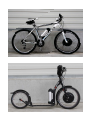
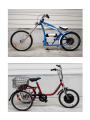
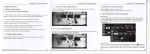
INSTALLATION MANUAL
EV-POWER.EU (GWL/Power group)
i4wifi a.s., Průmyslová 11, 102 19 Prague 10
Phone.: +420 277 007 500, Fax: +420 277 007 529
e-mail: [email protected]
http://www.evpower.eu
INSTALLATION MANUAL
Dear Customer,
Congratulations on purchasing your EV-BIKE, we believe you will be fully satisfied. The electric bike is one of
the most economical types of transport with minimal operating costs. Mounting kit EVBIKE is intended as
conversion kit of your existing bike to the bike with electric drive.
EV-BIKE set is compatible with almost every mass-produced bike. We rocommend you before installation
consult compatibility and extent of adjustments with your nearest EVBIKE service partner. The up to date list
of the partners can be found on the website www.evbike.cz in "Partners" section.
Most bicycles is designed for a maximum load up to 120 kg (weight of the rider, bike and accessories). EVBIKE
set is also designed for such load. In case of exceeding weight limit, it is necessary to select rim with spokes
designed for higher load. Information about special rim will provide you our your service partners.
In rare cases it could happen that you do not like purchased product, or you have found fact in the assembly
manual that would prevent you from using EVBIKE kit, please return back EVBIKE kit before installing in the
original packaging. For the current warranty conditions and the possibility of returning, please contact your
dealer who will advise you on how to proceed.
We wish you many happy kilometers!
EVBIKE SET IS SOLD AS A KIT. FOR SAFETY AND COMPLIANCE WITH LEGISLATIVE
REQUIREMENTS, THE FINAL PRODUCT IS FULLY GUARANTEED BY THE BIKE OPERATOR
OR WHOEVER ASSEMBLED AND SOLD THE BIKE.
WE RECOMMEND ENTRUST THE INSTALLATION TO A PROFFESIONAL BIKE SERVICE.
PLEASE CAREFULLY READ THIS INSTALLATION MANUAL BEFORE YOU START THE EVBIKE
CONVERSION.
2
INSTALLATION MANUAL
TABLE OF CONTENTS
1. Changing of rim with motor ......................................................................................... page 5
2. Pedal assistant ........................................................................................................... page 7
3. Controller and cabling .................................................................................................. page 8
4. LCD panel instalation ................................................................................................... page 9
5. Brakes, accelerator, handle ........................................................................................... page 11
6. Battery installation ..................................................................................................... page 12
7. Charging .................................................................................................................... page 15
SPECIFICATIONS
●
Motor power:
up to 500 W / 36 V (limited to 250 W)*
●
Motor weight:
6,6 Kg
●
Maximum speed:
up to 40 km/h with pedal assistence (limited to 25 km/h)*
●
Driving range:
30 - 70 km - depending on pedalling intensity, nature of the terrain and
used battery type
●
Size and material of rim:
26" or 28" x 1,75", Alluminium alloy 6061, (double wall)
●
Maximum rim load:
50 - 70 kg, total bicycle load up to 120 kg must not be exceeded
(includes the weight of the rider, bike and EVBIKE set)
●
Drive:
front/rear
●
Battery types:
Lithium 36 V, capacities 10 Ah, 7 Ah and 6 Ah
●
Battery Weight:
4,8 kg (10 Ah), 3,1 kg (7 Ah) and 3,6 kg (6 Ah)
* Due to European laws for electric bikes, maximum speed is limited to 25 km/h. The limitation can be set off for running at private
roads etc.
3
INSTALLATION MANUAL
KIT FOR CONVERSION OF BIKE TO ELECTRIC BIKE (EV BIKE)
EVBike is one of the cheapest vehicles with minimal running costs. This assembly pack is meant for conversion
of your current bike to electric bike.
EVBIKE HUB motor
LCD display
Pedal assistant
Sensor
Sensor
Magnet
Brake levers
Magnet
Accelerator
Battery
Controll unit
For succesful assembly of EVBike, you will also need following:
●
●
●
●
●
strip belts (to hold cables)
screws, nuts, washers
usual assembly tools
special bottom bracket tools (Fig. 1a - 1c)
basic technical skills
a
b
c
1
4
INSTALLATION MANUAL
DETAILED MANUAL
1. Installing EVIBIKE HUB motor
●
Remove the original wheel and swap tire to the EVBIKE HUB motor rim.
●
Insert the EVBIKE HUB motor into the fork. When installing, make sure the correct direction of rotation.
The cable come out on right side of the fork when bike is in the normal position. Otherwise the wheel will
run backwards against direction of way.
2
●
3
Mounting of the rim differs bike to bike. For all bike types we recommend to use the torque arm. See Figures
2, 4, 5. The torque arm will eliminate the reaction torque on axe (Fig. 6). Torque arm is partof the optional
accessories and is not included in basic package.
4
5
5
INSTALLATION MANUAL
Direction of engine
torque
Reaction torque
on axle
Axle spinout and spread dropouts
Example of torque arm installation
6
CAUTION
In any case, it is necessary to ensure tight connection nuts, washers and fork surface. Insufficient
nut tightening may cause wheel dropping out of the fork. The connection between wheel and fork
must be firm and stable (Fig. 7).
Fork
Nut
Motor
Engine
shaft
spring washer (not included)
7
8
NOTICE
When you install the hub motor to the rear wheel (Fig. 8), proceed the same way. There are only
following differences between front and rear wheel installation.
●
In addition, you must dismount the freewheel shimano gears. To dismount the freewheel use a special pinion
puller (Fig. 1b). The rear hub motor is ready for mounting freewheel with screw pinion. For most bikes
equipped with 7 gears shimano wheel is a screw pinion. For bikes with 8 gears or more gears is not
recommended to use the rear hub motor because here is a potential of many complications during
the installation. For bikes with 8 and more gears we recommend to use the front wheel hub motor.
●
The cable come out on left side of rear fork when the bike is in normal position.
●
After installation the hub motor you will need to adjust the sorting of gears. Its needed to avoid a collision
with the hub motor.
6
INSTALLATION MANUAL
2. Pedal assistant
●
When you start pedal, the pedal assistant will automatically adjust motor power.
●
To install this part, you have to remove spindle. Removing requires special tools (Fig. 1a, 1c).
●
Disassemble the bike parts as shown at the Fig. 9.
●
Mout plastic wheel with magnets in correct direction of rotation (shown on wheel by arrows).
pedal
pedal assistant
plastic wheel with magnets
pedal assistant
sensor
bike frame
Crankset
spindle
removable
ring
9
●
There must be about 2-5 mm space between plastic wheel and sensor. Depending on the type of bicycle,
the distance between the magnet wheel and sensor could be too small respectively large. Sensor ring sleeve
can be rotated and sensor bolted from the other side (Fig. 10).
2-5 mm
2-5 mm
10
●
Assembly all parts back. Before final tightening you should check the correct function of pedaling
detection.
TIP
If you mount kit on a scooter, or operate it only in accelerator mode, you can skip pedal assistant
assembly.
7
INSTALLATION MANUAL
3. Controller and cabling
Main wire for control elements
(LCD display, brakes, accelerator)
Speed sensor
Pedal assistant
Battery power
11
Motor connector
WARNING
Make sure proper cable connection! Conectors have different colors so risk of incorrect
connection is minimised (Fig. 11). In addition, they have locks against turn over. Use adequate
strength to connect connectors. If you use excessive force, you may damage the connectors!
Before connecting cables to the controller, make sure that all the pins inside the connectors are
properly seated. All pins must be in straight direction to the opposite connector body. Before cable
connecting, check the contacts and make adjustments to ensure perfect contact pins
with the opposite connector pins. Wrong cables or pins connecting can cause serious damage
of bike parts - especially the battery, motor and controller. Damages due the incorrect cable or pins
connecting will void your warranty
When connecting the motor connector and controller, make sure that the arrows on the connectors
facing each other (Fig. 13).
brake
accelerator
LCD display
brake
12
13
8
INSTALLATION MANUAL
4. LCD panel installation
Sensor
LCD display
Magnet
Control buttons
14
15
4.1. Installation of the LCD panel to the handlebar
The LCD panel (Fig. 14) can be installed on both sides of the handlebar (left or right). Please have in mind
the correct position of buttons – the lettering "MODE" must be read from the perspective of the rider. After
installation of the LCD panel please connect cable to the control unit.
16
2-5
mm
17
4.2. Installation the wheel speed sensor
Speed sensor (Fig. 15) must be installed as near to the control unit. In most cases this will be to the rear
wheel. Sensor attach to the frame. Magnet must be installed close to the speed sensor. The optimal distance
between the magnet and the speed sensor is about 5 mm. (Fig. 17) If the display does not show information
about speed and distance, the error is in the installation of speed sensor.
NOTICE
If the speed sensor or magnet are not installed correctly EVBIKE set turns off automatically 10
minutes after startup.
9
INSTALLATION MANUAL
THE LCD PANEL IS FULLY FACTORY CONFIGURED TO MEET THE LEGISLATIVE REQUIREMENTS
OF THE E-BIKES. SPEED IS REDUCED TO 25 KM/H AND ENGINE POWER TO 250W.
TIMER
BATTERY VOLTAGE INDICATOR
The battery indicator shows the approximate
value of the voltage, not the capacity of the
battery! When driving, battery voltage
changes and indicator can show a fully
discharged battery. This is a normal
phenomenon which depends on type
of the battery. For the real status of the
battery voltage is necessary to stop the bike.
SPEED
POWER ASSIST
UP TO 6 KM/H
(WALK)
18
POWER LEVEL
DISTANCE
4.3. Basic information about using the LCD panel
The panel displays driving information such as battery status. Displays the current, maximum and average
speed. Stores information about daily and total distance driven. The default rim size is 26 ".
LCD panel communicates with the controller. The panel allows changing the power level in 5 steps. You can
change the power level by pressing the buttons "UP" and "DOWN".
Longer holding the button "DOWN" will activate engine speed of 6 km/h. This feature can be used to start
the EVBIKE in case you have not installed accelerator (throttle).
The panel's backlight can be activated by simultaneously pressing buttons "UP" and "MODE" for 3 seconds.
Long press "UP" button to toggle current, maximum and average speed. Short press "MODE" button to switch
daily (TRIP) and total distance driven (ODO). Daily kilometers (TRIP) is always reset when you turn
off the display. Total kilometers (ODO) remain in the memory of LCD panel.
For detailed setup and use of the LCD panel, search for interactive tutorial at www.evbike.cz in "Operating
the computer" section.
NOTICE
Activation of the LCD panel is required to operate the bike. After switching on the battery, press
and hold the "MODE" button that will display information on the LCD panel and the bike can be
used. If you set engine power level to 0, the pedal assistant is inactive.
10
INSTALLATION MANUAL
5. Brakes, accelerator, handle
●
First disassemble the original equipment.
●
Controls assemble in this order see Figure 19. Accelerator and LCD can be installed on left or right side
according to user preference.
brake
brake
ring
spacer
LCD display
handle
accelerator
LCD controller
shorten
handle
handlebar
19
20
NOTICE
If you operate bike in pedal assistant mode you can skip the installation of accelerator. Unused
connector on the combined wiring harness must be insulated against moisture.
11
INSTALLATION MANUAL
6a. Battery installation - battery on the bike frame
A
B
21
22
●
To connect the battery to the controller you must loosen screws of two-piece cover (A and B, Fig. 22)
on the bottom of the battery holder, connect the connectors and tighten them sufficiently
(Fig. 23, 24). Screw connector cover back.
●
All screws must be tightened sufficiently to avoid the transient resistance effect when discharging
(C, D, Fig. 23). This effect can cause the battery deep discharge, short circuit or damage to the material due
to excessive temperatures. Screws tighten with adequate force to prevent damage of the battery terminals.
●
Battery holder is mounted into the holes on the bike frame designed for mounting bottle cage (Fig. 21).
C
D
23
●
24
Finally, insert the battery into the holder and lock key. Please pay attention to the right and gently fitting
the battery into the holder - ensures long life of the latch mechanism.
Putting into operation
The battery is put into operation by switching the green button located on the bottom right of the battery
holder (fig. 21).
12
INSTALLATION MANUAL
6b. Battery installation - battery on carrier
27
25
A
B
C
26
28
●
For battery holder assembly, you need 4 pcs of M8 screws including pads and nuts. Lenght of screws depends
on your bike construction. These screws aren’t part of package.
●
Fasten the lower spacer rods to carrier (Fig. 27). Rods allow set carrier to the three differnt positions (Fig.
26). Select the optimal height to have carrier in horizontal position. (Bolts aren't included in basic package).
●
Attach the rods to the bike frame using holes next to the chainrings cartridge (Fig. 28).
29
30
●
Use Curved rods (Fig. 27) to attach carrier to bike frame under the seat. Use the supplied screws and lock
nuts (Fig. 29).
●
Choose correct distance and fix the rods to carrier using provided screws (Fig. 30).
●
When the carrier is attached to bike frame, attach the battery.
13
INSTALLATION MANUAL
6c. 10 Ah battery power switch
Default position of ignitor is UNLOCK. Turn the possition to PUSH and push the key inside. There is a lock at the
bottom of battery, which lock battery to the carrier. Then turn to OFF and right after to ON.
Now the battery is locked to the carrier and system is powered (Fig. 31).
ON
UNLOCK
OFF
31
WARNING
In case that your next ride will be longer than an hour always put the key in the OFF position.
In case that EVBIKE is not used for more than 24 hours, recharge the battery to full capacity,
remove it and store in a dry place.
This warning applies to all battery types.
14
INSTALLATION MANUAL
7. Charging
Proper charging
Lithium cells which contain EVBIKE batteries can be recharged at any level of charge or discharge - these
batteries have no memory effect. We recommend always after the ride, or during of extended ride pause
to recharge the battery so you can immediately enjoy full power and a long driving range. After recharge
always unplug the battery from the charger. Before using, let it to cool down (about 30 min).
●
Current state of charging is indicated by LED color lights on charger.
RED – charging in progress.
GREEN – charging finished (charger is now disconnected from battery).
●
The charging time is 3-6 hours depending on battery condition.
EVBIKE set is equipped with a light energy recovery. Energy recovery works eg. when a speed is 30 km/h
downhill, motor automatically starts to generate power and recharge the battery. Driving at this speed must be
at least 10 sec. Energy recovery is reflected on the LCD display by battery voltage indicator. It shows full charge
status. The motor puts a slight resistance and sounds like when driving. Bike then not accelerating, nor slowing
down. Brake Energy Regeneration in the common terrain can return to about 5% of the energy.
Proper discharging
Recharge the battery to full capacity after the the first disconnection of protective controller. Never try to
reuse the battery after protective disconnection! Deep discharge of some cells and their unrepairable damage
may happen! Such battery usage may also cause unbalance of battery cells voltage and decrease their
capacity. In extreme cases, the battery can not be recharged again. This kind of damage can be easily
diagnosed and will result in avoiding your warranty.
Balance charging
Inside the battery is an electronic battery protection - balance circuit (compensates the voltage of the cells
to the same value). When using the battery cells voltage is always softly unblanced and we recommend after
about 8-10 charging cycles to leave the battery on the charger even after charging is completed. The battery
is still charged by a small maintenance current flow and balance circuit equals the voltage of cells to the same
level. Therefore double the charge time compared to standard time. Do not perform balance charging every
time you recharging the battery. It may shorten service life of the battery cells. We recommend balance
charging especialy before first ride and always, if you suppose that the battery has not its standard power!
TIP
The first time charging, we recommend charging four hours longer, even if the light is green.
There is a battery cell balancing.
15
INSTALLATION MANUAL
Storage
If you do not use the bike for more than 1 hour, always disconnect the battery using its power switch. If you
do not use the bike for more than 24 hours, always remove the battery, recharge it and store in a safe dry place
at room temperature. Beware of short-circuit the battery terminals (contacts) when storing and handling.
For long-term storage, such as off-season, it is also necessary check battery every 14 days (using LEDs) and
after 1 month recharge the battery to its full capacity. If you do not perform this maintenance deep discharge
of the battery cells will occur. This irreparable battery damage is not covered by warranty.
WARNINGS FOR BATTERY USE - POSSIBLE DANGERS
Danger of shortcut and follwing fire
Charged or uncharged cells contains a high amount of electric power, it may cause a electric sparks when
contacts are in shortcut. Batteries are not flammable, but fire may be created from sparks or high
temperature connectors (temperature caused by shortcut).
Danger of injury caused by DC current
When connecting more cells or batteries to serie, the danger of injury increases. Never touch the electric
wires or other componnents that are powered.
Chemical material danger
Lithium cells and batteries does not contain any caustics or acids. Still materials that are affecting human
body are inside. We recommend you to use following guidelines when manipulating with Lithium cells.
• Eye protection: use eyewear to prevent intrusion of any chemicals in eye.
• Skin protection: use protection clothing and gloves. Prevent contact of chemicals with your skin.
• Inhale protection: Manipulate with cells or batteries only in ventilated areas.
16
INSTALLATION MANUAL
End user instructions
Batteries and cells can be used only by person, instructed to use Lithium batteries and cells. This nstruction
is done by last reseller. When the batteries are sold and shipped, instruction is done via enclosed manual, more
details to be found at reseller website.
Warnings
Protect against unqualified manipulation, protect against kids. Protect against water or other liquids. Use the
batteries with control or constant managment of Battery protection/control system. Protect the cells and
batteries against overcharge and deep discharge. Don’t brake battery case, don’t manipulate with damaged
batteries.
Battery and cell recyclation – legal obligation informations
a) Of the manner of re-collection; for this purpose, the seller publishes actual list of affordable way to take
back and separated collect. Including at least name of the place and address.
Place to take back and separated collection: i4wifi a.s., Průmyslova 11, Praha 10
b) About possible negative effects of materials used in batteries or accumulators to environment and human
health.
Batteries and cells contain chemical materials that have negative effect on environment and human
health.
c) About meaning of graphical symbol for separated colletion or take back and about meaning of markings
THIS IS GRAPHICAL SYMBOL FOR SEPARATED COLLECT OR TAKE BACK.
DO NOT PUT BATTERIES TO MUNICIPAL WASTE BUT HANDLE THEM IN PLACE
FOR SEPARATED COLLECT OR TAKE BACK.
BEFORE THE FIRST RIDE CHECK THE TIGHTNESS OF ALL BOLTS
AND FUNCTIONALITY OF ALL SYSTEMS INCLUDING WHEEL BRAKES.
Global World Logistic Ltd.,EU-VAT ID: CZ682998344, as legal entity authorized by manufacturer for EU, hereby declares,
that the device is in compliance with basic requirements and further relevant provisions of directive LOW VOLTAGE
DIRECTIVE 2006/95/EC which sets technical requirements for electric devices of low voltage. This declaration is issued
on documents provided by Manufacturer.
17