1
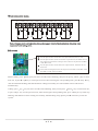
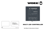
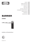
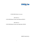
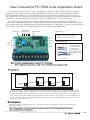
User manual for FC-7664 zone expansion board
It is an optional fitting of FC-7664, can expand 24 zones. It can be used as wired or wireless
extensions, can connect with 3 expansion boards when used as wired, each board has 8 zones,
distinguished by address. Can only connect with 1 expansion board when used as wireless, it
can expand 24 zones, please preset DIP switch before you power on the expansion board. At the
same time , you must make sure expansion zone is enabled in FC-7664 system menu.
FC-7664 can expand 24 zones via zone expansion board, but it is alternative from zone
expansion board and keypad zone, it detect zone expansion board in priority, when BUS detected
zone expansion board, keypad zone is ignored automatically, when didn t detect zone expansion
board in the continuous 15s, the keypad zone will be enabled automatically.
communication
indicator light
Address DIP
Mode Selection
Mode Selection
Up
B
Down
Terminal
block
Short circuit: wireless mode
Open circuit: wired mode
Terminal block
Exit
connect to panel
A
Entry
Red
Blue
Grey
Black
Red
Grey
Blue
Black
connect with zone
expansion board
B terminal block
connect with the
panel or zone
expansion board,
please refer to left
Explanatory Diag
ram.
B Terminal block
Note: When the communication is normal, LED 1,2 flashing .
When code the wireless device, LED 1,2,4,8,16 (BIN) is zone indicator light.
Wiring diagram
FC-7664
board 1
board 2
board 3
Terminal
block
Note: the wire between the panel and expansion board can not be more than 1m.
You can set the zone expansion board after you entering project setting. Firstly , finish DIP switch setting
for reference DIP switch as below, then connect the zone expansion board with the control panel, the
communication indicator light will flashing, you can input your password to enter setting status from FC7664, then 5 LED light will flashing at the same time, press Entry key last for 3s, the 5 LED light will
all off, it indicate you has entered zone expansion board setting status, after finishing setup, please press
Exit key to exit the system.
Wireless coding
Wireless coding is compatible with all of wireless products of our company, except remote controller,
emergency button.
Note: when you set it as wireless mode, please choose short circuit of mode selection ,then enter
zone expansion board setting status
Wired connection mode:
Z1
COM
NO
Z2
Z3
NO
NO
COM
NO
Z6
NO
10K
NC
Z8
10K
NC
COM
NO
10K
NC
Z7
NO
10K
NC
Z5
NO
10K
NC
Z4
10K
10K
10K
NC
COM
NC
NC
Note: when you set it as wired mode, please choose open circuit of mode selection, then enter zone
expansion board setting status.
DIP switch
when the panel connect with the first zone expansion board, DIP 1,2 is ON
when the panel connect with the second zone expansion board, the DIP of the first
zone expansion board remain unchanged. The second zone expansion board DIP 1
is OFF, DIP2 is ON
when the panel connect with the third zone expansion board, the DIP of the first
and second
board remain unchanged, the third zone expansion board DIP1 is ON,DIP2 is OFF
when DIP1,2 is OFF, make it disabled.
Delete coding: press
next one, or press
Down
Up
key last for 3 seconds, LED 1 flashing, then you can press
Down
key to select previous one, after selecting the corresponding zone, press
key to select
Entry
key ,
then all LED will flashing, that indicate delete coding successfully, the zone number will be subtracted 1
automatically.
Coding: press
Up
or press
key to select previous one, after selecting the corresponding zone, press
Up
key last for 3 seconds, LED1 flashing, then you can press
Down
flashing, that indicate wireless coding successfully, after finishing setup, please press
system.
key to select next one,
Entry
Exit
key, LED stop
key to exit the