1
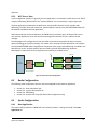
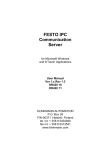
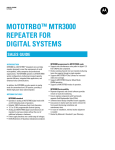
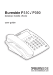
Sprite Setup and User Manual TW200 and TW25X Visit us on the web: www.tallysman.com Sprite User Manual 1 Document Amendment Record Revision Date Comments Rev 1.0 2 Mar 2012 Preliminary Release Rev 1.1 4 Apr 2012 Added section Double Taps and High Speaker Volume Rev 1.2 12 Oct 2012 Added support for Connect Plus Rev 1.3 22 Nov 2012 Added Forms Lite Copyright Copyright 2010 Tallysman Wireless Inc. All Rights Reserved. This document and the subject matter herein are proprietary items to which Tallysman Wireless Inc. retains an exclusive right to reproduction, manufacture and sale. This document is submitted in confidence, for the use of the recipient alone, or in conjunction with Tallysman Wireless Inc. and its licensees, and for no other purpose whatsoever unless permission for further disclosure is expressly granted in writing. Information in this document is subject to change without notice. Tallysman Wireless Inc. 106 Schneider Road, Unit 3 Ottawa, Ontario K2K 1Y2 Tel: 613 591 3131 Fax: 613 591 3121 Sprite User Manual 2 Table of Contents 1 1.1 1.2 1.3 INTRODUCTION.............................................................................................................................. 5 Sprite Platforms – TW200 and TW25X .............................................................................................................5 Applications ......................................................................................................................................................5 PC Software ......................................................................................................................................................6 2 QUICK GUIDE ................................................................................................................................... 7 3 TW200 INSTALLATION................................................................................................................ 8 3.1 3.2 3.3 3.4 3.5 3.6 3.7 4 4.1 4.2 4.3 5 5.1 5.2 5.3 5.4 5.5 5.6 5.7 5.8 5.9 5.10 6 6.1 6.2 6.3 6.4 6.5 7 7.1 7.2 7.3 7.4 7.5 Preparing the Radio ..........................................................................................................................................8 Connectors .......................................................................................................................................................8 Digital Inputs.....................................................................................................................................................9 Power and Ignition ...........................................................................................................................................9 Interconnection ................................................................................................................................................9 TW200 and GPS Antenna Placement..............................................................................................................10 Verifying Connection to MOTOTRBO Radio ...................................................................................................10 TW25X INSTALLATION ............................................................................................................. 11 Preparing the Radio ........................................................................................................................................11 Loading Sprite Firmware.................................................................................................................................11 Commissioning ...............................................................................................................................................12 RADIO CONFIGURATION ........................................................................................................... 15 Rear Data Cable Type .....................................................................................................................................15 Enable Option board ......................................................................................................................................15 Enable GPS ......................................................................................................................................................15 Ignition Sense .................................................................................................................................................15 Telemetry / IO ................................................................................................................................................15 ARS Setting .....................................................................................................................................................16 Button Mapping..............................................................................................................................................17 Emergency ......................................................................................................................................................18 Receive Call Group ..........................................................................................................................................18 Connect Plus Specific Settings ........................................................................................................................19 SPRITE CONFIGURATOR ........................................................................................................... 20 Hardware Setup ..............................................................................................................................................20 Application Setup ...........................................................................................................................................20 Reading and Writing Settings .........................................................................................................................21 Saving To File ..................................................................................................................................................22 Expert Mode ...................................................................................................................................................22 TELEMATICS GUIDE .................................................................................................................... 23 Application Description ..................................................................................................................................23 Available Events ..............................................................................................................................................23 Report Data ....................................................................................................................................................24 Radio Configuration ........................................................................................................................................24 Sprite Configuration .......................................................................................................................................24 Sprite User Manual 3 7.6 7.7 8 8.1 8.2 8.3 8.4 8.5 8.6 8.7 9 Channel Loading .............................................................................................................................................28 Testing ............................................................................................................................................................29 PASSTHRU GUIDE ........................................................................................................................ 30 Application Description ..................................................................................................................................30 Host System Configurations ...........................................................................................................................30 Radio Configuration ........................................................................................................................................31 Sprite Configuration .......................................................................................................................................31 Considerations and Limitations ......................................................................................................................33 Hardware Setup ..............................................................................................................................................33 Testing ............................................................................................................................................................33 MAN-DOWN GUIDE...................................................................................................................... 36 9.1 9.2 9.3 9.4 Application Description ..................................................................................................................................36 Radio Configuration ........................................................................................................................................36 Sprite Configuration .......................................................................................................................................37 Disclaimer .......................................................................................................................................................38 10 FORMS GUIDE ........................................................................................................................... 40 10.1 10.2 10.3 10.4 10.5 10.6 10.7 Application Description ..................................................................................................................................40 Radio Configuration ........................................................................................................................................40 Sprite Form Builder.........................................................................................................................................40 Forms and Forms Lite .....................................................................................................................................41 Sprite Configuration .......................................................................................................................................41 Modifying a Form ...........................................................................................................................................41 Testing ............................................................................................................................................................42 11 APPENDIX – DATA REVERT .................................................................................................. 43 12 APPENDIX – TW200 FIRMWARE PROGRAMMING ....................................................... 44 13 APPENDIX – CABLE DRAWINGS .......................................................................................... 45 13.1 13.2 13.3 TW200 Radio Cable (27-0010-0).....................................................................................................................45 TW200 Configuration Cable (27-0019-0) ........................................................................................................46 TW200 Passthru Cable (27-0017-0) ................................................................................................................47 Sprite User Manual 4 1 Introduction 1.1 Sprite Platforms – TW200 and TW25X The Sprite™ family of hardware and software products by Tallysman Wireless can add intelligent applications to the MOTOTRBO™ professional digital two-way radio systems without in any way compromising voice use. Tallysman Wireless offers the Sprite on two platforms for MOTOTRBO™: The Sprite™ TW25X is a software solution, loaded onto the MOTOTRBO™ expansion board. The TW25X family includes the TW250 (Telematics), TW251 (Man-Down), and TW255 (Forms). The TW25X is compatible with all Mototrbo network topologies except for Connect Plus. The Sprite™ TW200 is a small hardware device, which connects to the MOTOTRBO™ mobile radio Mobile Accessory Port (MAP). The TW200 provides two serial COM ports for connecting peripherals such as Mobile Data Terminals and RFID readers. The Sprite™ TW200 is compatible with all Mototrbo network topologies. Figure 1 - Sprite TW200 Hardware 1.2 Applications The Sprite products can be used for a number of different applications. An application may be restricted to a specific Sprite platform. 1.2.1 Telematics The Telematics application is available on both the TW200 and TW25X. The Sprite telematics application greatly extends the GPS and IO features of the MOTOTRBO radios with autonomous smart reporting including waypoints, IO based reporting, distance travelled, high rate Sprite User Manual 5 logging, vehicle idle time and odometer, PTT ID with GPS location and much more. 1.2.2 Passthru The Passthru application is only available on the TW200. The TW200 provides RS232 pass-thru connectivity for peripheral devices such as Mobile Data Terminals (MDTs) or SCADA Remote Terminal Units (RTUs) to send data transparently over a MOTOTRBO radio system. 1.2.3 Man-Down The Man-Down application is only available on the TW25X. The Man-Down application provides an effective Lone-Worker monitoring system. It provides loneworkers and workers in hazardous environments with means to call for help in the event of an emergency and for automatic alarm generation in the event of a potential man down occurrence. 1.2.4 Forms The Forms application is only available on the TW25X. The Forms application provides an effective tool for collecting data from the field using MOTOTRBO radios. Radio users can enter data (e.g. meter readings, time & attendance, refueling information) into a form using the MOTOTRBO radio interface and send the data to a host application. 1.3 PC Software A PC is required for setup and configuration of the Sprite products. Windows XP, Vista and Windows 7 operating systems are all compatible (32 or 64 bit). The following PC applications should be installed: MOTOTRBO CPS: This application is used to configure MOTOTRBO radios. It should be obtained from Motorola. Sprite Configurator: This application is used to configure Sprite products. The installer (spritecfgsetupX_X_X.exe) can be obtained from Tallysman. Sprite Program Loader: This application is used to load Sprite firmware onto the MOTOTRBO expansion board. This is only necessary for the TW25X family. The installer (spriteldrsetupX_X_X.exe) can be obtained from Tallysman. Sprite Form Builder: This application is used to design forms that are programmed into the Sprite Forms application. This is only necessary if using the Forms application. The installer (spriteformsetupX_X.exe) can be obtained from Tallysman. Sprite User Manual 6 2 Quick Guide The goal of this document is to aid the reader in installing and configuring the Sprite products smoothly, while having to read as little of this document as possible. Before starting, the necessary PC software should be installed, as described in Section 1.3. The appropriate installation section should be followed (either TW200 Installation or TW25X Installation). After completing the installation steps, the Sprite should be configured for use. Section 6 Sprite Configurator describes how to read and write the configuration for the Sprite products. The suitable application guide section(s) should then be followed. These sections describe the applications in greater detail and what configuration settings should be changed in the Sprite products and the MOTOTBRO radios. Sprite User Manual 7 3 TW200 Installation 3.1 Preparing the Radio The MOTOTBRO radio must be running R1.07.00 (or later) firmware. Before proceeding to the next steps, the radio configuration must be updated to set the rear data cable type (Section 5.1 Rear Data Cable Type). 3.2 Connectors There are three connectors on the TW200: 1) “Radio” (P1): Used to connect the TW200 to the MOTOTRBO radio. 2) “Config” (P2): Used to connect the TW200 to a PC for configuring the TW200. Also used to connect to another device (e.g. an MDT) to send/receive passthru messages. 3) Power Connector: A 6 pin molex connector that provides power and other inputs to the TW200. The power connector provides the following inputs: Pin 1 2 3 4 5 6 Description Power (+12 Volts) Ground Digital Input 2 Digital Input 3 Digital Input 4 Ignition Input Wire Color Red Black White Green Blue Yellow Figure 2 - Power Connector (looking into the pins) The power cable is 1 foot long and is provided with flying leads. The power connector should be connected as explained in the following steps: 1) Connect OV (Ground) to the black wire on the TW200 power connector. 2) Connect a fused 12V to the red wire on the TW200 power connector. 3) Connect the vehicle’s switched ignition input line to the yellow wire on the TW200 power connector. The ignition line on the TW200 must be pulled high to power up the TW200. 4) The remaining leads only need to be connected if you are sensing inputs for IO based telemetry events (e.g. door opening). Sprite User Manual 8 3.3 Digital Inputs The TW200 provides 3 general purpose inputs for monitoring events (e.g. a door opening and closing). These are the Digital Input 2, 3 and 4 pins on the Power Connector. The input logic low is 0V to 0.7V and the input logic high is 0.8V to 24V. Figure 3 shows the input circuit. Figure 3 - Digital Input Diagram 3.4 Power and Ignition To take advantage of the TW200 power control capabilities, the TW200 should be powered directly from the vehicle’s battery with the ignition line from the vehicle connected to the TW200 ignition input. The TW200 provides a Time-OFF-Timer signal to the radio input “ignition sense”. When the ignition is turned off the TW200 will remain powered until it completes an orderly shutdown at which time the TW200 will turn the radio off (with the ignition sense input) and itself thereby preserving battery power. The Time-Off-Time default time is 10 seconds but this parameter can be extended in using the TW200 Configurator application. 3.5 Interconnection Figure 4 shows the recommended TW200 and Mototrbo radio interconnect diagram. Figure 4 - Recommended TW200 Interconnection Sprite User Manual 9 3.6 TW200 and GPS Antenna Placement The TW200 gets its GPS information from the GPS integrated in the MOTOTRBO radio. For best results position the GPS antenna on the vehicle roof with a clear view of the sky. For optimum performance allow a 4 inch (10 cm) radius metallic ground plane, however if a metallic ground plane is not available the GPS antenna is sensitive enough to operate without a ground plane. The TW200 must be installed within 18 inches of the radio so that radio cable connection can be made. When installing the TW200 equipment the following safety concerns should be observed: 3.7 Placement of components shall not impede driver visibility nor render the vehicle unsafe to operate. Ensure equipment placements and cable/wire routes do not impede vehicle air bag deployment. Verifying Connection to MOTOTRBO Radio It is important to test that the TW200 is successfully communicating with the Mototrbo radio before proceeding to the next sections. Power should be applied to the MOTOTRBO radio and the TW200. The TW200 should be connected to the MOTOTRBO radio with the radio cable (part 27-0010-0). 3.7.1 Display Radios When the TW200 creates a connection to the MOTOTRBO radio it will display a message on the radio display. The message displayed is “Sprite” and the version of the TW200 firmware, e.g. “Sprite 4.2.04”. Cycle the power on the TW200 to force it to reboot and connect to the radio, then watch the radio display and within 15 seconds you should see the “Sprite” message being displayed if the TW200 is successfully connecting to the radio. When the radio is operating in Connect Plus mode the display will show “NON IP Connected” instead of the Sprite version. 3.7.2 Non-Display Radios The LED on the TW200 can be used to verify the connection for both display and non-display radios. There are three modes that the LED can operate in: 1) Permanently on: The TW200 is connected to the radio. 2) Permanently on, with flicker: The TW200 is not connected to the radio (the TW200 will “flicker” off very briefly once a second). 3) On/off flashing: The TW200 is connected to the radio and the radio has a valid GPS fix (the flashing is on and off for equal amounts of time). If the LED is in mode (1) or (3), then the connection to the radio is successful. 3.7.3 Troubleshooting Common reasons for not connecting: 1) The radio’s rear port was not configured for rear data, see Section 3.1. 2) There is a problem with the radio cable if you are making your own. Compare your radio cable against cable drawing provided in Section 13.1. 3) Make sure the radio cable is connected to the “Radio” port on the TW200. Sprite User Manual 10 4 TW25X Installation 4.1 Preparing the Radio The MOTOTRBO radio must have a Motorola expansion board (Motorola part number QA01638) preinstalled in the radio. The radio must be running R1.07.00 (or later) firmware. Before proceeding to the next steps, the radio configuration must be updated to enable the option on all channels (Section 5.2 Enable Option board). You should see the following icon on the radio display: 4.2 Loading Sprite Firmware The Sprite Firmware must be loaded onto the option board. This is done using the PC application Sprite Program Loader, which should be launched after installing. The Radio IP Address of the radio must be provided. By default the IP address is 192.168.10.1, unless it was modified in the Network page of the radio configuration. Click the “…” button and browse to the firmware file (.hex extension) that should be loaded. Figure 5 – Sprite Program Loader Click the Write Sprite Firmware button to start writing the Sprite firmware to the expansion board. The Sprite User Manual 11 process should take approximately 6 minutes. Figure 5 shows the Sprite Program Loader after a successful firmware load. When the Sprite firmware is running a message will be displayed on the radio shortly after the radio powers up. The message shows the version of the firmware, e.g. “Sprite 0.2.10”. 4.3 Commissioning After loading the firmware into the expansion board the Sprite will run in a demo mode until it has been commissioned. The demo will run for 48 hours of the radio being powered on; afterwards it will only run for 10 minutes each time the radio is powered on. While running in demo mode the message “Sprite Demo” is shown momentarily on the radio display after powering on. Commissioning is the process of licensing the TW25X on the expansion board. It involves requesting a System ID from the Sprite and sending the file to Tallysman via email. Tallysman will reply with an Authentication Key file which is used to write the key to the Sprite which completes the commissioning process. A detailed description of the process is explained below. The Sprite Configurator is used for creating the System ID and writing the Authentication Keys. The TW25X will remain commissioned if updated Sprite firmware is loaded onto the expansion board. 4.3.1 Obtain System IDs Launch the Sprite Configurator and ensure that it will use the TW25X platform by selecting ToolsSettings, see Figure 6. Figure 6 - Settings 1) Click the System ID button in the toolbar. You may have to read the Sprite configuration for this button to appear. The current commissioning status will be shown, see Figure 7. 2) Enter the Customer ID. This is a number provided by Tallysman; contact someone from Tallysman if you do not have a Customer ID. 3) Select the features/applications that you will be using. 4) Click the Get New System ID button. A new System ID will be displayed. 5) Click the Request Authentication Key button. This will add the System ID generated in the previous step to a request file. 6) Repeat the previous steps for all TW25Xs that need to be commissioned. Sprite User Manual 12 Figure 7 - Requesting System ID If the Sprite already has a System ID, it can be overwritten by getting a new System ID. However, Authentication Keys that were created for overwritten System IDs are no longer valid. 4.3.2 Get Authentication Keys Locate the request file(s) in the folder “My Documents\Tallysman Sprite\Key Requests”. The request files are marked with the current date (e.g. all requests made on March 1st 2012 will be in the file “KeyRequests_20120301.csv”). If requests were created on more than one day, there will be multiple files. The request file(s) must be emailed to Tallysman Wireless at [email protected]. An authentication key file (“AuthKey*.csv”) will be generated and emailed back; the turnaround time is should not be more than one business day. The request files and authentication key files should never be modified. Sprite User Manual 13 4.3.3 Write Authentication Keys to Sprite They authentication key files are used to write the key to the Sprite. 1) Click the Commission button in the toolbar. You may have to read the Sprite configuration for this button to appear. The current commissioning status will be shown. 2) Click the “…” button and browse to the key file(s) that were provided by Tallysman Wireless. More than one key file can be selected. The Sprite Configurator will find the key that was specifically generated for the connected radio. 3) Click the Write Authentication Key button to write the imported key to the Sprite. 4) Repeat the previous steps for all TW25Xs that need to be commissioned. Figure 8 - Writing Authentication Key Sprite User Manual 14 5 Radio Configuration This section describes the changes that should be made to the MOTOTRBO radio configuration using the MOTOTBRO CPS software. The changes that must be applied depend on the platform of the Sprite and the application(s) used. The application guide sections will indicate which changes should be made to the radio configuration. The CPS application should be put in “Expert” mode enabled (ViewExpert) in order for all of the settings to be visible. The radio dealer is responsible for all other MOTOTRBO radio configuration settings that are not mentioned in this section (e.g. voice channels, data revert channels, contact lists, etc.). 5.1 Rear Data Cable Type Applies to: TW200 In the Accessories page, change the Cable Type to Rear Data Accessory. This must be done before attempting to connect a TW200 to the MOTOTRBO radio. 5.2 Enable Option board Applies to: TW25X For all channels, enable the Option Board checkbox. This must be done on every channel configuration. 5.3 Enable GPS Applies to: Telematics Application In the General Settings page, the GPS checkbox should be enabled. 5.4 Ignition Sense Applies to: TW200 If the radio power on/off should be controlled by the TW200, then in the Accessories page, the Ignition Sense should be set to Follow Ignition Only. This also assumes that the radio ignition line is controlled by the TW200 as indicated in the TW200 installation section. 5.5 Telemetry / IO Applies to: Telematics Application These steps must be followed in order to allow the Sprite to read the status of the GPIO pins on the MOTOTRBO radio. In the Accessories page, the GPIO Physical Pins that need to be monitored should be mapped to a Sprite User Manual 15 Telemetry VIO. For example, see Figure 9. The GPIO pins available depend on the model of the MOTOTRBO radio. Figure 9 - GPIO Mapping In the Telemetry page, the Telemetry VIO features should be set to Send Status; Call Mode should be set to None. This allows the Sprite to read the VIO status from the radio. See Figure 10. Figure 10 - Telemetry Set To Send Status 5.6 ARS Setting Applies to: All In general, the ARS setting should be set to Disabled on all channels. This ensures that unnecessary registration and deregistration messages do not hamper the radio network. However, there are two exceptions where ARS should be set enabled (i.e. set to On System Change or On System/Site Change): 1) If a host application expects to receive ARS messages. If using the WCP Server as the host application, then ARS can be disabled. 2) If GPS Revert is being used on a conventional or IP Site Connect channel (to allow the Sprite to send messages on a data revert channel). In this case ARS must be enabled in order for the CPS to allow a GPS Revert channel to be selected. However, the ARS messages can still be silenced Sprite User Manual 16 by making these additional changes to the radio (Figure 11): a. In the Network page, delete the value for ARS Radio ID. b. In the Network page, change the TMS Radio ID to the radio ID of the control stations for the host application. This lets the radio know that the Sprite is sending messages to a host application and the radio will send it over the GPS revert channel. Figure 11 - Silencing ARS Messages 5.7 Button Mapping Applies to: Man-Down Application and Forms Application Buttons must be mapped to the option board in order for the Sprite to detect certain button pushes. This is done in the Buttons page by mapping Radio Buttons and Accessory Buttons to Option Board Features. 5.7.1 Man-Down Application To allow the radio user to enable and disable the Man-Down feature, P2 short press and long press should be mapped to Option Board Feature 1 and Option Board Feature 2, respectively. If a radio button is intended to be used as a reset button (e.g. to reset an inactivity timer or Beacon Alert) in the Man-Down application, then that button should also be mapped to Option Board Feature 1. 5.7.2 Forms Application A button must be used to enter and exit the Forms application on the radio. For XPR4550 model radios, the No Dot Button short press and long press should be mapped to Option Board Feature 1 and Option Board Feature 2, respectively. For XPR6550 model radios, the Side Button 1 short press and long press should be mapped to Option Board Feature 1 and Option Board Feature 2, respectively. Sprite User Manual 17 Figure 12 - Button Mapping 5.8 Emergency Applies to: Man-Down Application The emergency system must be configured in the radio in order for the Man-Down application to generate a MOTOTRBO emergency. The CPS help should be used for details for configuring the emergency system. Then the Emergency System should be selected in the channel configurations. In order to use the Beacon Alert feature, the emergency Mode should be set to Emergency Alarm. If a radio should be notified when a peer radio has entered emergency, then Emergency Alarm Indication and Emergency Call Indication should be enabled in the channel configurations. This option is only available to display radios. 5.9 Receive Call Group Applies to: Passthru Application (RS232 Host system configuration) In the RS232 host system configuration for passthru, the Sprite transmits passthru messages using group broadcasts. The radios must be set up to receive the data messages for the group calls. 1) In the ContactsDigital page, add a Group Call contact and enter a Call ID (the value used for the Call ID will be added to the Sprite configuration as well). 2) In the RX Group ListsDigital page, add the previous Group Call contact to the list. 3) In the channel configurations, set the Group List to the RX Group List containing the Group Call. If there is already a group contact being used for voice calls, it is recommended to add a separate group contact to be used for the data calls (i.e. for the Passthru application). Sprite User Manual 18 5.10 Connect Plus Specific Settings Applies to: TW200 operating on a Connect Plus system These settings should be set in the Mototrbo Connect Plus Option Board CPS (Figure 13): 1) Check the Enable Packet Data Call option. 2) Set the Minimum Packet Data Request Interval to 10 seconds. Figure 13 - Connect Plus Option Board Settings Sprite User Manual 19 6 Sprite Configurator This section describes the Sprite Configurator application and how to read and write the settings in a TW200 or TW25X. The application guide sections should be followed to understand which settings must be changed. 6.1 Hardware Setup 6.1.1 TW200 See Figure 14 for how to hook up the TW200. The configuration cable should connect the “Config” port on the TW200 to a COM port on a Windows PC. Figure 14 - TW200 Configuration Connections 6.1.2 TW25X The MOTOTRBO radio should be connected to the PC via the same USB cable that is used to configure the radio with the CPS application. The Sprite firmware must be installed on the option board first (section 4.2 Loading Sprite Firmware). Also, the MOTOTRBO USB drivers must first be installed on the PC, which can be done by installing the CPS application. 6.2 Application Setup The Sprite Configurator must be setup correctly so it can communicate with the attached TW200 or TW25X. This is done by selecting ToolsSettings from the menu, which will bring up the window shown in Figure 15. Sprite User Manual 20 1) For TW200: Select Mototrbo (TW200) and the COM port that the TW200 is connected to. The Radio IP Address can be ignored. 2) For TW25X: Select Mototrbo (TW25X). The default Radio IP Address is 192.168.10.1 unless it was changed in the Network section in the CPS application. Figure 15 – Configurator Settings 6.3 Reading and Writing Settings With the Sprite connected to the PC as indicated in Section 6.1, the Read and Write buttons will start the process of reading and writing the settings from the Sprite. Once the settings are read, they are displayed in the Sprite Configurator, similar to Figure 16. A description of a setting is displayed on the bottom of the screen when it is clicked. Figure 16 - Sprite Configurator Sprite User Manual 21 When reading the settings for a TW25X that has not yet been commissioned, you will be asked to choose which applications you want to configure, as shown in Figure 17. Figure 17 - Select Features (TW25X) After writing the settings, the Sprite should be restarted to make sure the new settings take effect. For the TW25X this means turning the radio off and on. 6.3.1 Troubleshooting If you are having difficulties reading and writing the settings: 1) Go to ToolsSettings and make sure the values are correct. 2) If the error “No database for version…” is displayed when reading the settings, then the Sprite Configurator must be updated and the latest installer should be obtained from Tallysman Wireless. 3) For the TW25X it is possible that the radio has not connected to the PC correctly. You can attempt to read the radio configuration with the CPS application to check if the radio is connected to the PC. 4) For the TW200 make sure you are using the correct cable. The configuration cable (27-0019-0) can be easily confused with the passthru cable (27-0017-0) since they have the same connectors. 6.4 Saving To File The settings can be saved to a Sprite configuration file using the Save button and opened using the Open button. Sprite configuration files have the extension “.spr”. 6.5 Expert Mode Going to Tools->Expert Mode from the menu will enable expert mode. This will display “expert” parameters which were previously hidden. Typically, the expert parameters will not need to be changed. Sprite User Manual 22 7 Telematics Guide 7.1 Application Description The Telematics application has the ability of reporting GPS, IO, odometer and other information to a host application, where the data can be presented to an end-user. The Sprite uses smart event based reporting where events can be individually configured to report the desired information to the host application. Available events include periodic events, ignition on/off, IO trigger, moving/stopped and distance travelled. Multiple reports may be bundled together and sent in one transmission, greatly increasing the network efficiency and reducing GPS data overhead. All reports are logged to persistent memory in the Sprite, which is not lost over power cycles. The data remains in the log and is available to be retrieved by a capable host application. The log can hold approximately 40000 reports, which translates to 30 days of logging at a 1 minute reporting interval. When the limit of the log has been reached, the oldest reports are replaced. 7.2 Available Events The following events are available to generate reports: PTT Event: Triggered when the PTT key on the radio initiates a call. Periodic Event: Triggered on a regularly timed interval. VIO Event: Triggered when a specific input line goes high and/or low. Distance: Triggered when the vehicle has travelled a certain distance, based on an internally generated GPS odometer. Emergency: Triggered when the radio has entered emergency mode. GPS Fix Event: Triggered when a GPS fix is obtained after a period of not having a valid GPS fix. GPS No Fix Event: Triggered when a GPS fix is lost after a period of having a valid GPS fix. Ignition On Event: Triggered when the ignition has been turned on. The ignition line must be monitored directly by the TW200 hardware. (TW200 only) Ignition Off Event: Triggered when the ignition has been turned off. The ignition line must be monitored directly by the TW200 hardware. (TW200 only) Radio On Event: Triggered when the radio and TW200 have been turned on. Radio Off Event: Triggered when the radio is about to be turned off. For the TW200, the radio power must be controlled by the TW200 using the ignition sense input. Speeding Event: Triggered when the average speed of a vehicle over a specified time interval exceeds a threshold. Moving Event: Triggered when the vehicle starts moving after it has been stopped. The vehicle is considered moving when its speed exceeds a threshold or if it has moved by a certain distance. Stopped Event: Triggered when the vehicle is stopped for a certain amount of time after it has been moving. Turn: Triggered when the bearing changes by at least 60o while travelling at a minimum speed. Waypoint: Triggered when a configured waypoint is entered or exited. Sprite User Manual 23 7.3 Safe Area Event: Triggered when the “safe area” designated by the configured waypoints is left. RSSI Capture: Triggered when an RSSI reading is measured from a received voice call. Tracking Event: A special event that must be triggered by another event (e.g. Emergency Event). When it is triggered, reports will be generated at a faster rate for a period of time. Report Data The following data fields can be included in a report when an event has been triggered: Latitude and Longitude: The GPS position information. GPS fix time: The time of the last valid GPS fix. Speed (horizontal): The horizontal speed at the time of report. Bearing: The direction at the time of report. Altitude: The altitude at the time of report. Odometer (full): The Odometer value, this is based on distance calculated from GPS. The Odometer does not wrap. Run time and idle time: The vehicle Run time (total time the ignition is on and the vehicle is moving) and Idle times (total time the ignition is on and vehicle is stopped) are reported. VIO status and VIO changed: Reports the current status of all VIO lines and also indicates which VIO line(s) triggered the report. Event Time: The time the event was triggered. The GPS fix time must also be selected if the Event Time is selected. Average speed: A horizontal speed that is averaged over a time interval. Waypoint ID: The ID of the waypoint that triggered the event. This field only has relevance on Waypoint Events. More fields are available. However, these are the more useful fields of the bunch. 7.4 Radio Configuration The following radio configuration sections must be completed for the Telematics application: Section 5.1 - Rear Data Cable Type (for TW200) Section 5.2 - Enable Option board (for TW25X) Section 5.3 - Enable GPS Section 5.4 - Ignition Sense (optional) Section 5.5 - Telemetry / IO (optional) Section 5.6 - ARS Setting 7.5 Sprite Configuration 7.5.1 Host Application The Host Application tab defines where the report data will be sent to. When the radio is operating in Connect Plus mode, the Sprite will send data to the XRT Radio ID. When the radio is operating in any other mode, the Sprite will send data to the Base Radio ID and Base UDP Port. 1) Set the Base Radio ID to the radio ID of the MOTOTRBO radio control stations used by the host Sprite User Manual 24 application. From the dropdown, PC should be selected. 2) Set the Base UDP Port to the port that the host application uses to receive messages from the Sprite. For the Tallysman WCP Server this should be 4010. For a Neoterra server, Neoterra should be consulted for the correct value. 3) Set the XRT Radio ID to the radio ID used by the XRT 9000 Gateway. This is only used when operating in Connect Plus. 7.5.2 Reporting Rate Limits To ensure that an individual Sprite does not overload the radio network with excess data, the number of transmissions attempted by the Sprite can be throttled. The Sprite will only attempt a maximum number of transmissions over a certain period of time. This is configured with the Max Transmissions and Quota Time Interval settings in the Bandwidth tab. The default values are 10 and 600 seconds, respectively, which means that over a period of 10 minutes the Sprite will only attempt 10 transmissions. If the limit is reached, the accumulated reports will be sent in a bundle when the Sprite is allowed to do its next transmission. 7.5.3 Events (General) Individual events must be configured using the appropriate tab under the Events node in the Sprite Configurator tree, as shown in Figure 1. Figure 18 - Configuring an Event Sprite User Manual 25 The following should be done when configuring an individual event: 1) Check the Event Enabled checkbox. 2) Select the data to be included in the report with the Report Form. At the very minimum Latitude and Longitude, GPS fix time and Event time must be enabled. 3) Some events have settings that are specific for that event (e.g. Time Interval for the Stopped event); these settings should be reviewed after reading their descriptions. 7.5.4 Periodic Events The Periodic event is an event that is commonly used. The Time Interval should be set to how often a report should be generated. The Periodic Options allows the event to only be triggered when the vehicle is moving and/or stopped, and only if a valid GPS fix is available. Four instances of the Periodic event are available for extra flexibility. A common setup is to have Periodic #1 set to only Report while stopped with a longer Time Interval (e.g. 30 minutes), and Periodic #2 set to only Report while moving with a shorter Time Interval (e.g. 5 minutes). This will greatly reduce the amount of data over the radio network. 7.5.5 VIO Events The VIO event is another event that is commonly used. 1) A VIO event can trigger when an IO input line goes from low to high, high to low, or both directions; this is selected in the VIO Trigger Conditions setting. 2) Select the input lines that should cause the event to trigger with the Lines to Watch setting. 3) If the MOTOTRBO radio inputs are being used, then in the Miscellaneous tab the Use radio VIO checkbox should be enabled. Four instances of the VIO event are available; however, only one is typically needed. If for instance, Input 2 should only trigger a VIO event when it goes from low to high, and Input 3 should only trigger a VIO event when it goes from high to low, then two separate VIO events must be used for each input. 7.5.6 Waypoint Event Up to 20 waypoints can be configured in the Sprite so a report is generated when a waypoint is entered and/or exited. Waypoints are approximated by a circle, which is defined by a latitude and longitude position and a radius. To configure waypoints, the Waypoint event must be enabled and individual waypoints must be configured in the Waypoints tab. For each waypoint configure these settings: 1) Latitude and Longitude should be set to the center of the waypoint. The values used should be entered as decimal degrees. For latitude this is a value between -90 and 90. For Longitude this is a value between -180 and 180. For example, the Tallysman Wireless office in Ottawa has latitude of approximately 45.3402 and longitude of -75.9040. 2) Set the Radius for the appropriate size of the circle centered at the latitude and longitude. 3) Enable one or both of the Report on enter or Report on exit checkboxes. 4) The One time fire and One time pending options are reserved for use by a host application and should be left unchecked. Sprite User Manual 26 7.5.7 Bundling Reports Multiple reports can be bundled together and sent in one transmission, greatly increasing the efficiency of the data system and allowing a much higher reporting rate. Individual events can be set to be bundled. When these events are triggered, the report generated will not be immediately transmitted to the host application. Instead, the report will wait on the “bundle queue” and will be transmitted in a bundle when one of these conditions is met: If a report has been waiting in the bundle queue for a certain amount of time. If the bundle queue has reached its maximum size. If a non-bundling event has been triggered, in which case all reports in the bundle queue will be added to the transmission of the non-bundling report. A common use of bundling reports is to enable bundling for a 1 minute Periodic event and set the max bundle size to 5. In this scenario, a GPS report is generated every minute and on every 5th report, a bundle of last 5 reports are transmitted to the host application. It is also useful to bundle reports from VIO events if it is expected that many reports will be generated. The following settings should be set for configuring bundling: 1) For each event that should be bundled, enable the Bundle report checkbox. 2) In the Bandwidth tab, set the Bundle Max Size to the number of reports that should be on the bundle queue before transmitting reports in a bundle. It is recommended that this value should be no higher than 10. 3) In the Bandwidth tab, set the Bundle Timer to the longest amount of time that a report should wait on the bundle queue before it is transmitted. 7.5.8 Acknowledged Reports Important reports can be configured to require an acknowledgement from the host application to ensure that it has been received by the host application. When the Sprite sends a report that requires an acknowledgement to the host application, it expects to receive an acknowledgement from the host application. Otherwise, the next time the Sprite sends a report to the host application, it will indicate if the Sprite has other reports that have not yet been acknowledged. When the host application is notified that the Sprite has unacknowledged reports, the host application has the option of sending a message to the Sprite to retrieve its unacknowledged reports. Thus, the Sprite will never attempt to automatically re-send reports until they are acknowledged, which could cause havoc on a radio system. Instead, it is the responsibility of the host application to ask the Sprite for the reports that it did not receive. To configure acknowledged reports: 1) For each event that requires very reliable reporting, enable the ACK required option in the Event Options. 2) In the Bandwidth tab, the Unacked Count Window determines how far back unacknowledged reports should be retrieved. The default is 28800 seconds (8 hours), which means that the host application will only attempt to get unacknowledged reports from the last 8 hours. DISCLAIMER: Acknowledged reports can add substantial data traffic to the radio network since Sprite User Manual 27 additional data messages are needed in order to make the reporting reliable. It is recommended to only use this feature for events that happen fairly infrequently. It is not intended to be used by settings all events to use the ACK required option. You may ask your host application provider for recommendations. 7.5.9 Time Off Timer Applies to: TW200 The TW200 and MOTOTRBO radio have the ability to remain powered on for a configurable period of time after the vehicle ignition has been turned off. Afterwards, the TW200 will (optionally) trigger a Radio Off event and (always) power down the radio and itself. This is useful if you don’t want the radio to be powered off automatically when the ignition is turned off. This assumes that the TW200 and radio are wired up as recommended in Section 3.5 (i.e. both the radio and TW200 connected directly to the battery, the vehicle ignition line is connected to the TW200 and the TW200 provides the ignition sense line going into the radio). In the Miscellaneous tab, the following parameters can be changed: 1) The Time Off Timer is the length of time that the TW200 and MOTOTRBO radio should remain powered on after the ignition is turned off. 2) After the Time Off Timer has expired, the Radio Off event is triggered (if it is configured). The Pending Shutdown Timer is the length of time given to the radio to transmit the Radio Off report before the TW200 and radio are powered off (15 seconds should be adequate). 7.5.10 Miscellaneous 1) If data revert is being used on a conventional or IP Site Connect system, then in the Miscellaneous tab, the Use GPS Revert (conventional) checkbox should be enabled. 2) If the radio is also using Enhanced GPS, then in the Expert tab, the LMP Periodic Enabled checkbox should be disabled. Expert mode must first be enabled in the Sprite Configurator. 7.5.11 Connect Plus Settings Applies to: TW200 operating on a Connect Plus system The following parameters should be modified in the Expert tab if the TW200 is being used on a Connect Plus system: 1) 2) 3) 4) 5) 7.6 Set the Send Retry Limit to 3. Set the TMP Query Period to 600 milliseconds. Set the Inter Message Delay to 10000 milliseconds. Set the Radio Busy Delay to 2000 milliseconds. Uncheck all options for the WDT Flags. Channel Loading When configuring events for the Telematics application, it is important to consider the capacity of data messages that the radio network can handle. The two biggest factors for how frequently the Sprite should generate reports are (1) how many radios are sharing the system and (2) how many data Sprite User Manual 28 channels are available. As a rule of thumb, one data channel can comfortably handle 1000 data transmissions an hour. Tips for reducing the number of data transmissions and increasing channel efficiency: 1) Bundle all reports that can be bundled. 2) If using Periodic events, using one Periodic event for when the vehicle is moving (on a short time interval) and another Periodic event for when the vehicle is stopped (on a long time interval). 7.7 Testing Testing should be done by forcing an event condition to trigger and viewing the report in the host application when the transmission has completed. In the Miscellaneous tab in the Sprite Configurator the Display message on event and Generate tone on event options can be enabled for testing. When an event is triggered, these options will cause the radio to show a message on the radio display and generate a tone, respectively. However, this will only work on a non-Connect Plus system. Sprite User Manual 29 8 Passthru Guide 8.1 Application Description The Passthru application on the TW200 provides RS232 connectivity for peripheral devices (such as Mobile Data Terminals and SCADA Remote Terminal Units) to send data transparently over a MOTOTRBO radio system. The TW200 with the MOTOTRBO radio will act as a communication pipe to pass arbitrary data from one end of the system to the other. When the TW200 receives RS232 data on the passthru port from a peripheral device, it will transmit that data over the radio network as a “passthru packet”. When the TW200 receives a “passthru packet” it will forward the data to the peripheral device connected to the passthru port. 8.2 Host System Configurations There are two possible system configurations for the host application when using the Passthru application. The system configuration that is used will affect how the TW200 and MOTOTRBO radio is configured. 8.2.1 RS232 Host In this configuration (shown in Figure 19), the host application is connected to the passthru port of a TW200. The passthru packets are transmitted to a group broadcast. RS232 Host Application or Peripheral Device TW200 MOTOTRBO Radio MOTOTRBO Radio TW200 Peripheral Device MOTOTRBO Radio TW200 Peripheral Device RS232 Subscriber Units Figure 19 - RS232 Host Configuration When the host application sends data to the connected TW200, the data will be broadcast to all radios that belong to the configured talkgroup. The TW200s on the receiving side will pass that data to the peripheral devices. Since all peripheral devices will receive the data, peripheral addressing information should be inherent in the data protocol used by the host application. Similarly, when a peripheral device sends data to the TW200 over the passthru port, that data will be sent to the host application as well as the all other peripheral devices. All radios must be sitting on the same channel and there is no data revert. This mode is not supported over a Connect Plus system. This offers “plug and play” solution for systems that need a pipe for sending RS232 data over large Sprite User Manual 30 distances. 8.2.2 WCP Server Host In this configuration (shown in Figure 20), the host application is connected to a WCP Server over TCP/IP using the proprietary WCP Protocol. The “passthru packets” are transmitted to a single target radio. The host application sends data to the WCP Server using the WCP Protocol, which includes radio addressing. The WCP Server will extract the “passthru packet” and send it to the MOTOTRBO radio with the address provided by the host application. When the peripheral device sends data to the TW200 over the passthru port, the data will be sent to only the host application, which will receive the message from the WCP Server in a WCP Protocol message. The advantage to this configuration is that the radios connected to the peripheral devices have the option of sending the “passthru packets” over a data revert channel since the WCP Server can interface to multiple MOTOTRBO radios using different frequencies. Also, target radio addressing is handled in the WCP Protocol so the “passthru packet” does not need to provide radio addressing. However, development is required for the host application to interface to the WCP Server. RS232 Host Application WCP Server MOTOTRBO Radio MOTOTRBO Radio TW200 Peripheral Device MOTOTRBO Radio TW200 Peripheral Device TCP/IP using WCP Protocol Subscriber Units Figure 20 - WCP Server Host Configuration 8.3 Radio Configuration The following radio configuration sections must be completed for the Passthru application: Section 5.1 - Rear Data Cable Type Section 5.4 - Ignition Sense (optional) Section 5.6 - ARS Setting Section 5.9 - Receive Call Group (for RS232 Host configuration only) 8.4 Sprite Configuration 8.4.1 Host Application This section defines where the TW200 will send “passthru packets”; settings are found in the Host Application tab. Sprite User Manual 31 8.4.1.1 For RS232 Host System Configuration 1) Set the Base Radio ID to the Call ID that was set up for the receive call group in Section 5.9. From the dropdown, Group Call should be selected. 2) Set the Base UDP Port to 4069. 8.4.1.2 WCP Server Host System Configuration 1) Set the Base Radio ID to radio ID of the MOTOTBRO radio control stations used by the WCP Server. From the dropdown, PC should be selected. 2) Set the Base UDP Port to 4010. 3) If using Connect Plus, set the XRT Radio ID to the radio ID used by the XRT 9000 Gateway. 8.4.2 UART Settings UART settings can be found in the Expert tab of the Sprite Configurator with Expert Mode enabled. 1) UART 0 Baudrate will modify the baudrate. 2) UART 0 Parity will modify the parity. 3) UART 0 Stop Bits will modify the stop bits. It is recommended to leave all other settings unchanged. UART 1 settings are not used. There is no hardware flow control. 8.4.3 Transmission Trigger When the TW200 receives data on the passthru port from an attached peripheral, there must be rules for when TW200 packetizes the received data and transmits it over the radio network. The Passthru tab is where those rules are defined. The configuration of the rules depends on the nature of the data used by the host application and the peripheral devices. The most common setup is to trigger the transmission after the peripheral device stops sending data to the TW200 over the passthru port. For this to work there must be a “break” in the serial communication after the peripheral device has sent its data. 1) In the Passthru Flags only Max Char Delay Enabled should be checked 2) The Passthru Max Char Delay should be set to the length of time that the TW200 must not receive any data for in order to trigger the transmission of the passthru packet. This must be at minimum 200 milliseconds. The other setup uses special characters to delimit the data that the TW200 should use in a passthru packet. This provides greater control over the transmission trigger. However, it requires that the nature of the peripheral device data adheres to a start and end character. 1) In the Passthru Flags only STX Char Enabled and ETX Char Enabled should be checked. 2) The Passthru STX Char should be set to the character that marks the start of a packet. It must be entered as a decimal value. 3) The Passthru ETX Char should be set to the character that marks the end of a packet. It must be entered as a decimal value. Sprite User Manual 32 8.5 Considerations and Limitations 8.5.1 Packet Size The TW200 will only send up to 300 bytes of data received from a peripheral device in a single transmission over the MOTOTRBO radio network. If more than 300 bytes of data is received by the TW200 before a transmission is triggered, some data will not be sent. 8.5.2 Radio Channel Throughput A MOTOTRBO™ data channel is a low speed data pipe with an effective over air data transfer rate of 1200bps. It is the responsibility of the peripheral devices and host application to ensure that the passthru packets generated do not overload the radio network. A single transmission of a passthru packet is expected to take 2-4 seconds, depending on the length of the packet. 8.5.3 Reliability and Acknowledgements Due to the nature of 2 way radio systems, the transmission of data is not 100% reliable. Common reasons for failure include data call collisions, radios being out of range and busy channels. The MOTOTRBO radio or TW200 do not provide feedback to the peripheral device to indicate if the passthru packet was sent successfully. If an acknowledgement is required, it must be provided by the host application or peripheral device that has received the passthru packet. 8.6 Hardware Setup In addition to the general TW200 hardware setup (Section 3.5), the TW200 must be connected to a peripheral device or a host application. The port labeled “Config” on the TW200 provides the RX, TX and ground pins used for RS232 communication. These pins must be connected to the correct pins on the peripheral device. Tallysman Wireless provides a cable (part number 27-0017-0) that will connect the TW200 to a COM port on a PC. See Section 13.3 for a drawing of the cable. For other peripheral devices, a different cable may be required depending on the pin out of the peripheral device connector. 8.7 Testing This section only describes testing a RS232 Host system configuration. 8.7.1 Test Setup Figure 21 shows the recommended setup for testing passthru. A PC is used for the peripheral device and any PC application capable of sending and receiving serial data over a COM port (e.g. HyperTerminal) is used for sending and receiving passthru data. Successfully completing this test will prove that the TW200s and MOTOTRBO radios have been set up correctly to handle passthru data. After this is verified, the actual peripheral devices should replace the PCs that have been connected to the TW200s. Both TW200s should be connected to a PC COM port using the passthru cable (27-0017-0). A single PC can be used for both TW200s if it has multiple COM port; the PC will also need to run multiple instances of a terminal program. Sprite User Manual 33 PC running terminal application TW200 MOTOTRBO Radio MOTOTRBO Radio 27-0017-0 Cable TW200 PC running terminal application 27-0017-0 Cable Figure 21 - Passthru Test Setup It is recommended to use RealTerm, a free terminal application that can be downloaded from http://realterm.sourceforge.net/. Documentation for RealTerm can be found on its website, but once it has been installed and launched, these are the important things to change: 1) In the Display tab, enable the Half Duplex checkbox; this will make RealTerm display both outbound and inbound serial data. 2) In the Port tab, select the correct Port, Baud, Parity and Stop Bits. Hardware Flow Control should be set to None. The Change button will apply the changes to the port. Click the Open button; it will be depressed when the port is open. 8.7.2 Sending and Receiving Data To send passthru data using Realterm, go to the Send tab, enter some text and click the Send ASCII button. The outbound data should show up as green in the console, as shown in Figure 22. This will cause the TW200 to transmit a passthru packet over the radio network which will be received by the other TW200. When the TW200 receives a passthru packet, it will be fowarded to the connected PC and displayed in the RealTerm console in yellow. Figure 22 - RealTerm Sending Data If using an STX and ETX character, then they must be included in the data sent by RealTerm. Binary data can be sent instead of text by entering the bytes as numbers and clicking the Send Numbers button. For Sprite User Manual 34 example “0x02 0x31 0x32 0x33 0x03” will send binary data 0231323303. 8.7.3 Troubleshooting 1) Make sure the passthru cable is used (27-0017-0); it is easy to confuse it with the configuration cable (27-0019-0). 2) Make sure the radio antennas are not too close; there may be interference. 3) Make sure the UART settings configured in the TW200 agree with the settings in RealTerm. Sprite User Manual 35 9 Man-Down Guide 9.1 Application Description The Man-Down application has the ability to generate MOTOTRBO emergency alarms by detecting radio tilt and user inactivity, which will notify a host application or a peer radio that an emergency has occurred. The Man-Down application is compatible with analog and digital channels. Inactivity Trigger Normal Operation Local Reminder Timeout MOTOTRBO Emergency Alarm Beacon Alert (optional) Tilt Trigger Trigger Reset Figure 23 - Man-Down Flow Diagram Figure 23 shows the flow diagram of the Man-Down application and its different states. It will stay in Normal Operation until either an Inactivity Trigger or Tilt Trigger is detected, which will start the Local Reminder. 1) Inactivity Trigger: This trigger is detected if there has been no “activity” from the radio user for a certain period of time. Activity can be a combination of a button press, physical movement of the radio (detected by accelerometers), and a “double tap” (also detected by accelerometers). 2) Tilt Trigger: This trigger is detected if the radio tilt exceeds a specific angle (default 60⁰) for a period of time. During the Local Reminder the radio will sound “reminder pip” tones to alert the user that the Local Reminder has started. The Local Reminder must be reset within a certain period of time or a timeout will occur which causes the MOTOTRBO Emergency Alarm will begin. To reset the Local Reminder, the radio must be put in an upright position for a Tilt Trigger or activity must be detected for an Inactivity Trigger. Resetting the Local Reminder will return the application to Normal Operation. The MOTOTRBO Emergency Alarm will transmit the emergency signal over the radio network. The MOTOTRBO Emergency Alarm will exit when the emergency has been acknowledged by another radio on the network or if a timeout occurs. The Beacon Alert is an optional feature that will sound local beacon tones when the MOTOTRBO Emergency Alarm has ended. This is to facilitate search for the location of the radio that caused the alarm. The Beacon Alert will continue until it has been reset (e.g. by a button push). 9.2 Radio Configuration The following radio configuration sections must be completed for the Man-Down application: Section 5.2 - Enable Option board Sprite User Manual 36 Section 5.7 - Button Mapping Section 5.8 - Emergency After configuring the emergency system in the radio it should be tested by manually pushing the emergency button on the radio to make sure that the radio is able to enter emergency mode. 9.3 Sprite Configuration All parameters described are found in the Man Down tab in the Sprite Configurator. 9.3.1 General 1) Enable the Man Down Enabled checkbox. 2) Set the Local Reminder Timeout to how long the radio user should be given to reset the Local Reminder and prevent the MOTOTRBO emergency. 3) Check the Allow user to enable or disable Man Down checkbox if you want to give the radio user the privilege of being able to enable and disable the Man Down application. If checked, a P2 long press will disable Man Down and P2 short press will enable Man Down. 4) The Allow user to request enable or disable Man Down setting is not implemented and should remain unchecked. 5) The Heartbeat feature requires a host application that implements this feature. Such a host application does not yet exist, so the Heartbeat Enabled checkbox in the Heartbeat tab should be unchecked. 9.3.2 Tilt Trigger 1) The Tilt Trigger is an optional feature. Enable the Tilt Alarm Options Enable checkbox if you want to use it; otherwise leave it unchecked and skip the rest of this section. 2) Set the Tilt Alarm Timeout to how long the radio should be tilted before starting the Local Reminder 3) Set the Tilt Minimum Angle to the angle that must be exceeded before the radio is considered tilted. It is recommended to use a value in the 45-60 degrees range. 4) Calibrate the tilt reference for “up” by clicking the Orientation button in the toolbar, see Figure 24. The radio should be still and upright for this procedure. Once complete, the calibrated values will be automatically copied to the Tilt Reference Orientation setting. Figure 24 - Calibrating Tilt Reference 9.3.3 Inactivity Triggers Inactivity Triggers can be configured with the “Watchdog” parameters. Two independent Inactivity Sprite User Manual 37 Triggers are provided for extra flexibility, but you may only need to use one. For example, Watchdog 1 can be configured to ensure that movement is detected at least every minute; and Watchdog 2 can be configured to ensure a button has been pushed at least every hour. 1) The Inactivity Trigger is an optional feature. Enable the Watchdog Enable checkbox if you want to use it; otherwise leave it unchecked and skip the rest of this section. 2) Choose what sort of activity will prevent the Inactivity Trigger from firing in the Watchdog Options. One or more type of activity should be selected: a. Reset timer on button push: If a button push is detected, the inactivity timer is reset. Only buttons that have been mapped to an Option Board Feature in the radio configuration will be detected. b. Reset timer on movement: If movement of the radio is detected, the inactivity timer is reset. c. Reset timer on double tap: If the radio is tapped twice in quick succession, the inactivity timer is reset. 3) Set the Watchdog Timeout to the length of inactivity required to start the Inactivity Trigger. 9.3.4 Beacon Alert 1) The Beacon Alert is an optional feature. Enable the Beacon Alert Options Enable beacon alert checkbox if you want to use it; otherwise leave it unchecked and skip the rest of this section. 2) Choose the condition(s) that should cause the Beacon Alert end in the Beacon Alert Options. At least one condition should be enabled; otherwise the radio must be reset to stop the Beacon Alert. 9.3.5 Double Taps and High Speaker Volume In some cases, it is possible for a high speaker volume to inadvertently cause double taps to be detected by the accelerometer. This can cause problems double taps are used to reset a Watchdog or the Beacon Alert. For example, the Local Reminder will emit a tone from the speaker and, if the volume is high enough, can register a double tap which will then cancel the Local Reminder when it should not have been cancelled. If these problems occur, then there are two configuration parameters that can be tweaked if the Sprite firmware version is 0.2.13 or greater: 9.4 Double Tap Sensitivity (X, Y) and Double Tap Sensitivity (Z) can be set to Low. This change should be done first. The Local Reminder Tone and Beacon Alert Tone can be set to the Low Frequency tone. This changes the sound that is played during the Local Reminder and Beacon Alert. The double tap recognition is not as sensitive to lower frequency sounds. Disclaimer It is impossible to reliably detect, with means within a portable radio, the many situations in which a worker may have become distressed or has need of assistance, and further, many additional factors can further impede reliable reporting of indicators of such an event, including defects in radio coverage, or defects arising with the radio, the radio network, and utility software. The Sprite™ TW251 software in conjunction with a MOTOTRBO™ radio, is a supplemental aid and must not be solely relied upon for the purpose of monitoring lone workers or for detection that a user has become incapacitated. Tallysman Sprite User Manual 38 Wireless will not accept any claims for losses, injuries or consequential damages, howsoever caused, from direct or indirect use of the Sprite™ TW251 Software product, regardless of whether product usage is compliant with recommended usage or not. Sprite User Manual 39 10 Forms Guide 10.1 Application Description The Forms application provides an effective tool for collecting data from the field using MOTOTRBO radios. Radio users can enter data (e.g. meter readings, time & attendance, refueling information) into a form using the MOTOTRBO radio interface and send the data to a host application. The forms that may be filled out by the radio user are highly customizable and must be programmed into the Sprite. A compatible host application is required to accept the form data. 10.2 Radio Configuration The following radio configuration sections must be completed for the Forms application: Section 5.2 - Enable Option board Section 5.3 - Enable GPS Section 5.6 - ARS Setting Section 5.7 - Button Mapping Figure 25 - Sprite Form Builder with a form loaded 10.3 Sprite Form Builder The Sprite Form Builder application is used to generate the forms that are programmed into the Sprite. A form must be generated and saved to a Sprite Form file, which will then be added to the Sprite Sprite User Manual 40 Configuration. The Sprite Form file has the extension “.sprform”. A form may be tested quickly in the Sprite Form Builder by selecting ToolsTest Form in PC from the menu. The Sprite Form Builder Manual should be read for a thorough description for how to use the Sprite Form Builder; it is available from Tallysman Wireless. Figure 25 shows a sample form loaded in the Sprite Form Builder. 10.4 Forms and Forms Lite A Sprite can be licensed for Forms or for Forms Lite. Forms Lite is restricted to using forms with a maximum of two fields, which cannot include a GPS position. There are no restrictions for the full Forms version. 10.5 Sprite Configuration 10.5.1 Host Application Tab The Host Application tab defines where the form data will be sent to. 4) Set the Base Radio ID to the radio ID of the MOTOTRBO radio control stations used by the host application. From the dropdown, PC should be selected. 5) Set the Base UDP Port to the port that the host application uses to receive messages from the Sprite. For the Tallysman WCP Server this should be 4010. For a Neoterra server, Neoterra should be consulted for the correct value. 10.5.2 Forms Tab 1) Click the Import… button for Form #1 and select the Sprite Form file that was generated by the Sprite Form Builder with extension “.sprform”. 2) Set the Form ID To Load to the ID of the form that was imported. For example, see Figure 26. 3) Forms #2-4 can be ignored. Figure 26 - Forms Tab 10.6 Modifying a Form When a form must be modified using the Sprite Form Builder (e.g. a new field is added or removed), then the Form Revision form the form must also be updated. It is recommended to increase the Form Revision by 1 every time a form is changed. This is done so the host application can determine how to interpret form data; otherwise errors may occur. After a form is changed, but must be re-imported in the Sprite Configurator and then written to the Sprite. Appropriate action must be taken in the host application so it is aware of the changes made to Sprite User Manual 41 the form. 10.7 Testing After the previous sections are complete the Sprite should be ready to fill out a new form. A short press of the purple button should enter the Forms application and you should see “Tallysman Forms” displayed on the radio. Push the OK button on the radio to start filling out a form. When you are finished filling out the form you should see “Form Complete << SEND?>>” on the radio display. Push the OK button and the form data will be sent to the host application. The host application should respond to acknowledge the form data or indicate that there was an error. If no response from the host application is received within 60 seconds, then “No Reply” is displayed on the radio. A long press of the purple button will exit the Forms application and return the radio to its regular menu. See the Sprite Forms User Manual for a thorough description of how to use the Forms application on the radio; it is available from Tallysman Wireless. Sprite User Manual 42 11 Appendix – Data Revert The Telematics, Passthru and Forms applications send data messages over the radio network. It is possible, and recommended, to use dedicated data revert channels for sending all these data messages. For Capacity Plus radio networks, if a data channel pool is added to the Capacity Plus radio network the Sprite will send data over the data channel pool. Otherwise the Sprite will send data over the voice channel pool. For conventional and IP Site Connect radio networks data revert is handled differently based on the version of the Sprite: 1) For TW200 with version 4.2.0 (or newer) and TW25X with version 0.1.9 (or newer): The Sprite will send data on the configured GPS revert channels. A GPS Revert channel should be configured for any voice channels. Section 5.6 should be followed for any radio configuration changes that need to be made related to ARS. In the Sprite Configurator, the Use GPS Revert (conventional) checkbox should be enabled in the Miscellaneous tab; this is the only circumstance where it should be checked. 2) For TW200 with version earlier than 4.2.0 and TW25X with version earlier than 0.1.9: The Sprite will manually change the radio’s channel in order to send data messages on a data revert channel. Voice channel and zone IDs and data channels and zone IDs must be added to the Sprite configuration to accomplish this. A configuration manual can be obtained from Tallysman Wireless to describe the process in detail. Sprite User Manual 43 12 Appendix – TW200 Firmware Programming The TW200 hardware is pre-loaded with the application firmware. In the unlikely event that the firmware has to be changed a Programming Box is required to update the firmware in the TW200. The TW200 Programmer Kit (part number 32-0002-1) consists of: (x1) TW200 Programming Box (32-0002-0) (x1) USB to Molex cable (27-0021-0) (x2) RJ45 to RJ45 Cables (27-0020-0) You will also need an additional PC application (the “Sprite Program Loader (TW20X)”) and a hex firmware file. Both can be obtained from Tallysman Wireless. 1) The Sprite Program Loader (TW20X) should be installed and launched. 2) The TW200 and the Programming Kit should be set up as shown in Figure 27. 3) Push the reset button on the Programming Box. USB drivers will be installed to the PC after the first time this is done. Depending on your operating system, the driver installation can be automatic or manual. For a manual install (likely for an XP computer), it will ask you drivers files to use. The driver files to use can be found in "C:\Program Files (x86)\Tallysman\Sprite Program Loader (TW20X)\driver"; tell the driver installation wizard to use these files. 4) You can verify the USB drivers were installed successfully if you see a new item "LibUSB-Win32 Devices" with a sub-item "AT32..." 5) In the PC application, select the hex firmware file by clicking the “…” button and browse to the file. 6) Click the “Load Firmware” button to load the firmware onto the TW200. Figure 27 - TW200 Firmware Programming Sprite User Manual 44 13 Appendix – Cable Drawings 13.1 TW200 Radio Cable (27-0010-0) This cable is used to connect the TW200 to the rear port of a MOTOTRO radio. Notes: 1) The MAP 5 pin on the radio must be connected to Gnd on the radio 2) Power-Off- Timer output is a controlled 12V DC 3) MAP connector Motorola Part # PMLN5072A provided with radio P1 ( rear Panel) Radio Connector Radio MAP Connector ( Not provided with radio cable) (SWB+) 7 ( Ignition Sense) 25 White 1 (Radio Detect) Orange 2 (Radio Control) ( *GPIO_2) 19 (GPIO_6) (GPIO_3) (GPIO_7) (GPIO_8) 20 21 22 24 (Vbus) 3 (D+) 1 (D-) 2 (USB Gnd return) 4 Radio Inputs 3 (Input 0) Bi-directional 4 (Input 1) Green Yellow Blue Brown (MAP5) 5 5 (Vbus) 6 (D+) 7 (D-) 8 (GND) 8P8C (RJ45) male (Gnd return) 8 Pin 1 = White Pin 2 = Orange Pin 3 = Black Pin 4 = Red Pin 5 = Green Pin 6 = Yellow Pin 7 = Blue Pin 8 = Brown View Looking into back of Connector Tie Wrap Cable Sprite User Manual 45 13.2 TW200 Configuration Cable (27-0019-0) This cable is used to connect the TW200 to a PC COM port for configuration. P2 ( Front Panel Connector) Blue (TX 3) 2 (RX Port 2) Yellow ( RX 2) 3 (TX Port 2) White (Gnd) 5 8 (GND) Black 6 (CNTR) 8P8C (RJ45) male DB9/F Pin 1 = Brown Pin 2 = Blue Pin 3 = Yellow Pin 4 = Green Pin 5 = Red Pin 6 = Black Pin 7 = Orange Pin 8 = White Sprite User Manual 46 13.3 TW200 Passthru Cable (27-0017-0) This cable is used to connect the TW200 to a PC COM port for the Passthru application. P2 ( Front Panel Connector) Green (TX 3) 4 (RX Port 1) Red ( RX 2) 5 (TX Port 1) White (Gnd) 5 8 (GND) Black 6 (CNTR) 8P8C (RJ45) male DB9/F Pin 1 = Brown Pin 2 = Blue Pin 3 = Yellow Pin 4 = Green Pin 5 = Red Pin 6 = Black Pin 7 = Orange Pin 8 = White Sprite User Manual 47