1
rha-
HEWLETT
~~ PACKA.RD
HP98645A
:Ye..uremeBt Library
U.I'I: LIbrary
HP 98645A
Measurement Library
User's Manual
F4;11
HEWLETT
It:'~ PACKARD
Update 3 (July 1988)
HEWLE'IT-PACKARD COMPANY
RosevUle Networks Dh'lslon
8000 Foothills Boulevard
RosevUIe, California 95678
Maaaal Part Number 98645-90001
E0684
Printed In U. S. A.
June 1984
PRINTING HISTORY
The Printing History below identifies the Edition of this Manual and any Updates that are included.
Periodically. update packares are distributed which contain repla~ment pages to be merged into the
manual, including an updated copy of this Printing History page. Also, the update may contain write-in
instructions.
Each reprinting of this manual will incorporate a.ll past updates; however, no new information will be
added. Thus, the reprinted copy will be identical in content to prior printings of the same edition with
the user-inserted update information. New editions of this manual will contain new information. as well
I.. updates.
98645-90001
Fint Edition . . . . . . . . . . . . . . . . . . . . . . . June
Update 1 . . . . . . . . . . . . . . . . . .. November
Update 2. . . . . . . . . . . . . . . . . .. December
Update 3. . . .. . . . . . . . . . . . . . . . . .. July
1984
1985
1987
1988
NOTICE
The information contained in this document is subject to change without notice.
HEWLETf-PACKARD MAKES NO WARRANTY OF ANY KIND WITH REGARD TO THIS
MATERIAL, INCLUDING, BUT NOT LIMITED TO, THE IMPLIED WARRANTIES OF
MER.CHANTABILITY AND FITNESS FOR A PARTICULAR PURPOSE. Hewlett-Packard shall
not be liable for errors contained herein or for incidental or consequential damages in connection
with the furnishing, performance or use of this material.
This document contains proprietary information which is protected by copyright. All rights are
reserved. No part of this document may be photocopied, reproduced or translated to another
language without the prior written consent of Hewlett-Packard Company.
Copyright C 1984,1985,1987,1988 by HEWLETT-PACKARD COMPANY
Update 3 (July 1988)
ii
I
MANUAL UPDATE
MANUAL IDENTIFICATION
Title:
HP 98645A Measurement Library
User's Manual
Part Number:
98645-9000 1
This Update Goes With:
UPDATE IDENTIFICATION
Update Number:
3 (July 1988)
This update also Includes:
Update 2 (December (987)
Update I (November 1985)
First Edition (June 1984)
THE PURPOSE OF THIS MANUAL UPDATE
is to provide new information for your manual to bring it up to date. This is important because it
ensures that your manual accurately documents the current version of the product
THIS UPDATE CONSISTS OF
this cover sheet, a printing history page (if any), any replacement pages, and write-in instructions (if
any). Replacement pages are identified by the update number at the bottom of the page. A vertical
line (change bar) in the outside margin indicates new or changed text material. The change bar is not
used for typographical or editorial changes that do not affect the conteni of the text.
TO UPDATE YOUR MANUAL
identify the latest update (if any) already contained io~ your manual by referring to the printing
history. page. Incorporate only the updates from this packet not already included. in your manual.
Following the instructions on the back of this page, replace existing pages with the update pages and
insert new pages as indicated. If any page is changed in two or more updates, such as the printing
history page which is furnished new for each update, only the latest page will be included in the
update package. Destroy all replaced pages. If write-in instructions are included they are listed on the
back of this page.
HEWLETf-PACKARD COMPANY
Rosel'Ule Networks DlvlsJon
8000 Foothills Boulevard
Rose\' Ille, California 95678
98645..90001
U0788
Update 3
July 1988
U-I
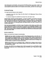
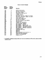
TECHNICAL MANUAL UPDATE
(9864'5-9000 I)
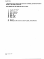
Note that .,*" indicates a changed page.
UPDATE
3
1&2
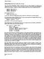
DESCRIPTION
Replace the following pages with the new pages attached:
: Title*Iii·
All of Section 1.
Replace the following pages with the new pages attached:
iiili,,*
2-3/2-4*
index-! */index-2*
index-3*/index-4
U-2
[USING THE LIBRARY
INTRODUCTION
The HP 98645A Measurement Library provides a set of easy-to-use subroutines for taking readings from
the HP 98640A Analog-to-Digital Converter (ADC) card. These subroutines can be used from the BASIC
or Pascal language systems on HP 9000 Series 200 or Series 300 computers. The subroutines are written
in Pascal, and are adapted to the BASIC language with the CSUB utility package. The Measurement
Library is compatible with BASIC 2.0, 2. 1, 3.0, 4.0, 5.0, 5.1, and Pascal 2. 0, 2.1, 3.0, 3. 1, 3.2.
The Measurement Library subroutine calls are a superset of the "liP 14751 A Computer Aided Test
Programming Package for the Model 6944A". BASIC programs written using the UP 147S1A routines
should be able to use the Measurement Library software with very little modification.
Features
The HP 98645A Measurement Library allows you to:
Take a single reading from any of 8 channels at any of 4 gains.
Take readings by .canning across 1 to 8 channels, any number of times.
Take readinp from channels in random order as specified in an address array. Optionally, you can
lpecify the ,ain and pace interval for each reading, and the readings can be repeated any number of
times.
Express readings in three different units:
Base units: binary integer returned from the ADC.
Standard units; base units adjusted for gain and calibration, expressed as real numbers.
Uler unite ltandard units times a user multiplier plus a user offset.
Take calibntion (zero) readings on a specified channel, and apply that calibration adjustment to all
readings.
Re-let gain or units at any time.
Take readings at the full S5 kHz sampling speed of the ADC card from either BASIC or Pascal
Take reading. under interr:lpt mode ill BASIC.
Update 3 (July 1988)
1-1
I
Using the Library
Software Provided
J
The HP 98645A Measurement Library includes these subroutine packages:
MEAS_LIB for use with BASIC 2.0
MEAS_Lffi3 for use with BASIC 3.0
MEAS_LIB4 for use with BASIC 4.0
MEAS_LIB5 for use with BASIC 5.0
MEASLIB42 for use with BASIC 4.0 on a Model 320 computer
MEASLIBS2 for use with BASIC 5.0 or 5.1 on a Model 320 computer
INTR2_1 for use with interrupt mode in BASIC 2.1
MEAS LIB.CODE for use with Pascal 2.0/2.1
MEAS_LIB3.CODE for use with Pascal 3.0/3.1/3.2
MEASLIB32.CODE for use with Pascal 3.1/3.2 on a Model 320 computer.
The software is provided on the following media:
Option #630: 3-1/2" floppy disc
Option #6 S5: 5-1/4" floppy disc
MEAS_LIB and MEAS_LIB.CODE will not use floating point hardware. MEAS_LIB3) MEAS_LIB4,
MEAS_LIB5, and MEAS_LIB3.CODE will use a Floating Point Math card if it is installed in the system;
otherwise they will use the Pascal floating point library routines. MEASLIB42, MEASLIBS2, and
MEASLIB32.CODE will use the built-in floating point hardware in the Model 320 computer; these
routines are not compatible with any other proceaor.
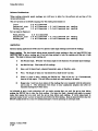
THE GENERAL APPROACH
The way you write programs using the Measurement Library is pretty much the .me whether you use the
BASIC or Pasc;a.llanguage system. There are, however, significant differenus in the way you set up YOUI
system environment. We will discu88 these differences in the next few paragraphs.
Using BASIC 2.1
If you are using the BASIC 2. 1 system, take the following steps to let your application up and runnin,:
1) Boot up BASIC'
z.. o.
2,) Load the BASIC 2.1 extensioDS. The 2.1 extensions are located on the Extended BASIC 2.1 disc,
Insert that disc into the master drive and issue the command LOAD BIN "AP2_1".
3) Load the interrupt processing package if you will be taking readings in interrupt mode. (In terr up'
mode readings are discuaed later in this section.) The interrupt processing package is located on th4
Measurement Library disc. Insert that disc into the master drive and issue the command LOA[
BIN "INTR2_1".
4) Load any otlaer BASIC extensions that you need for your application.
FOT
example, this would b
the time to load Graphics 2. 1.
5) Write your BASIC program or load a previously written program into memory.
In the paragnpb
below we will describe how to write your application program using the Measurement Library.
Update 3 (July 1988)
1-2
Using the Library
6) Load the Measurement Library subroutines if they are not already part of the program you wrote
in the pr·.vious step. The subroutines are located on the Measurement Library disc. Insert that disc
into the master drive and issue the command LOADSUB ALL FROM "MEAS_LIB".
7) Run your program. Debug as necessary (repeating steps 5 through 7).
Using BASIC 3.0, 4.0, 5.0, or 5.1
If you are using the BASIC 3.0, BASIC 4.0, BASIC 5.0, or BASIC 5.1 system, take the following steps to
get your application up and running:
1) Boot up BASIC 3.0, 4.0, S. 0, or 5. 1.
Z) Load the BASIC 3.0, 4. 0, 5.0, or S. 1 10 binary if you will be taking readings in interrupt mode.
(Interrupt mode readings are discussed later in this section.) The 10 binary is located on the BASIC
Language Binary disc. Insert that disc into the master drive and issue the command LOAD BIN
"10".
3) Load any other BASIC binaries that you need for your application. For example, this would be the
time to load graphics routines.
4) Write your BASIC program or load a previously written program into memory. In the paragraphs
below we will describe how to write your application program using the Measurement Library.
5) Load the Measurement Library subroutines if they are not already part of the program you wrote
in the previous step. The subroutines are located on the Measurement Library disc. Insert that disc
into the master drive and issue the command:
LOADSUB
LOAOSUB
lOADSUB
lOADSUB
lOADSUB
ALL
ALL
ALL
ALL
ALL
FROM
FROM
FROM
FROM
FROM
"MEAS LI B3"
11
"MEAS-LIB4
"MEAS-LIBS"
1t
"MEASLIB42
"MEASLIB52"
or
or
or
or
as appropriate for your system. (Refer to the paragraphs on "Software Provided", above, for
information on which software goes with which system.)
6) Run your program. Debug as necessary (repeating steps 4 through 6).
General BASIC Programming
The Measurement Library subroutines add approximately 23,700 bytes to your BASIC program. The
INTR2_1 binary adds approximately 1200 bytes.
Note that integer parameters used in the Measurement Library subroutine calls must be explicitly typed as
INTEGER. (You can find out which parameters are integers by looking at the parameter descriptions in
the lubroutine call listings in Section 2 of this manual.) Real parameters and string parameters (those
ending in $) need not be explicitly typed. Literal constants of any type (integer) real, or string) may be
used. Note that integers must not contain a decimal point.
You can invoke Measurement Library routines by callin. them (CALL statement) or simply by entering
them by name. When you use them in an IF .. THEN statement or an ON .. statement, the "CALL"
must be explicit.
Update 3 (July 19 8 8)
1-3
Using the Library
Using Pascal 2.0, 2.1, 3.0, 3.1, or 3.2
You can call the Measurement Library subroutines from th~ Pascal language by importing the
Measurement Library and using the library subroutines as procedure calls with the syntax described in
Section 2 of this manual. Typically, you import the Measurement Library with a compiler directive of
$SEARCH 'MEAS LIB'$ or
$SEARCH 'MEAS-LI83'$ or
$SEARCH 'MEASLIB32'$
and an import statement of
IMPORT mea8urement_lib;
in your code. Importing the Measurement Library adds about 17600 bytes to your Pascal program.
If the Pascal system modules INTERFACE and 10 have not been merged into the system libra.ry file. you
will allo have to include the compiler directive
$SEARCH 'INTERFACE.' ,'10.'$
Note that the "... after each file name is significant.
The procedure calls for the Measurement Library are all exported from the file MEAS_LIB.CODE (or
MEAS_LIB3.CODE), along with the following types:
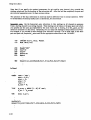
TYPE
8hortint = -32768 .• 32161;
byte II: 0 .• 255;
atr255 = atring[255];
larraytype = ARRAY[O •• maxlnt] Of ahortint;
rarraytype = ARRAY[O •• maxint] Of real;
rarraypt. = ""rarraytype;
iarraypt = ""iarraytype;
Due to the rigorous structure of the Pascal language, you can't default parameters in the procedure calls.
However, to save you the bother of declaring real and integer arrays for the pace and gain array
parameters of the random_scan procedure, you can use the default pace or gain value (established by a
call to Config_ 0 or Set_gain) by specifying a 0 for the array size and a NIL for the array pointer. All
other parameters for all procedure calls must be explicitly provided in the procedure call u real, integer
(or shortint), or string variables, or as constants or literal constants. For all array parameters, make sure
that the array elements are of the correct type, real or shortint; do not substitute integer for shortint.
And take care that the size parameter you pass for an array does not exceed the actual size you declared
for that array. (If you exceed the declared array size, you can write all over the other variables in your
program, and cause yourself much anguish.)
Once your Pascal program .has been written and compiled, it mUlt be merged or linked to the
Measurement Library using the Pascal system librarian program. Be sure to transfer ALL the modules in
MEAS_LIB or MEAS_LIB3. If 10 is not in your system library file you will also have to transfer the
module IOCOMASM from the file 10 (found on your LIB: disc).
Interrupt mode operation is not supported in the Pascal environment. (That means we don't guarantee
that it will work. If you try it and it doesn't work, you can purchase consulting services from the nearest
HP sales and service office. See the back section of this manual for a list of sales and service offices.) An
interrupt service routine (ISR) is required for interrupt mode to work in Pascal, and we do not provide a
PascallSR with the Measurement Library. If you try to use interrupt mode in Pascal without a proper
ISR, you will probably crash your system. If you're an experienced Pascal programmer, you may be able to
Update 3 (July 1988)
1-4
Using the Library
write you'" own ISR. For more information on
number 09826-90074.
ISR~
refer to the Pascal 2.0 System Desianer's
Guide~
part
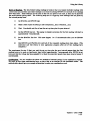
WRITING THE PROGRAM
In both BASIC and Pascal~ writing your application program involves two major activities: setting up the
card to take readings, and taking the readings. In addition, BASIC programs may take readings in
interrupt mode. We will cover these subjects in the paragraphs that follow. We will also say a few words
about externally paced readings.
All of the subroutine calls referred to below are described in detail in Section 2 of this manual.
Setting Up
Setting up an ADC card for readings requires allocation of a common area, as wen as calls to at least three
subroutines: Meas_lib_init, Confi,_ 0, and Init.
The common area serves as the heap space for the subroutines in the Measurement Library. It is allocated
automatically in Pascal; in BASIC you must allocate it explicitly at the beginning of your program.
Reserve this area by including the following statement in your program:
20
COM/Heapcomj INTEGER Heaparea(1:n)
where n is the size of the Heaparea array. The size of Heaparea is determined by the number of
configured names for ADC cards (more about that later) and the number of readings taken for calibration
(ditto). Use 53 integers for each ADC card configuration and 4 integers for each reading used in
calibration. We recommend using Heaparea(1:1300); this allows all 16 possible ADC card configurations
and a calibration run of 100 readings.
In both BASIC and Pascal, the subroutine calls to Meas_lib_init, Config_O, and Init do the following:
Meas_lib_init initializes the Measurement Library, and must be called before any other subroutines in
the library are called. Meas_lib_init needs to be called only once in your program.
Config_O sets up an ADC card for taking readings. At a minimum, you specify a name by which you
will call the card and the model number of the card. In addition~ you can specify the select code of the
card, its gain, a pace rate for taking readings, an error reporting parameter for normal mode overrange
errors, and the units (base, standard~ or user) in which the readings will be reported. (Reporting units
are discussed below.) If you do not supply these optional parameters, Config_O will supply default
values.
Init resets an individual card, disables interrupts for that card, and sets the calibration array for that
card to its default values. Init must be used before any other calls except Meas_lib_init, Config_O
and System_init. System_init is the same as Init, except that it initializes all cards that have been
configured.
Update 3 (July 1988)
1-5
Using the Library
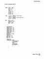
The set-up portion of a typical BASIC program might look like this:
90
100
COM/Heapcom/ INTEGER Heaparea(1:1300)
INTEGER Select code, Gain
Name$="ADC"
Model$=1I98640A
Select code=18
Gain=1
Pace=O.01
Error$="No"
Un 1t$=IIStanda rd"
220
230
240
Meas lib init
Conf!g O(Name$,Model$,Select code,Gain,Pace,Error$,Unit$)
Init(Name$)
-
20
30
40
50
II
60
70
80
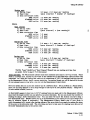
The analogous Pascal code would look like this:
CONST
name = 'ADC';
model = '98640A';
aelect code = 1S;
gain =-1;
pace = 0.01;
error = 'NO';
units • 'STANDARD';
multiplier
1.0;
off.et = 0.0;
=
BEGIN
meas lib inlt;
conrig OTname,lIodel,select code,gain,pace,error,units,multiplier,offset);
init(name);
-
The most frequently used configuration parameters can be reset without reconfiguring the card; these
parameters are ,ain, pace interval, and units. The gain can be reset with a call to the Set_Ia.in
subroutine, or a new gain can be specified as a parameter to the Input or Random_scan subroutine. (The
Input and Random_scan subroutines are used to take voltage readings from the ADC; they are described
later in this section.) A new pacing interval can be specified as a parameter to the Input,
Sequential_scan, or Random_scan subroutine. And the units can be reset with a call to the Set_units
subroutine. (Note that if you specify pace or gain parameters in an Input, Sequential_scan, or
Random_scan can, the specified pace or gain value holds only for the duration of the call; it reverts to its
previous value after the call completes.)
Update 3 (July 1988)
1... 6
Using the Library
Calibration
Calibration gives you a way of compensating for offsets that are inherent to the ADC card. To use the
calibration feature, you must first reserve one of the channels on the card and short the + Input and
- Input terminals on that channel to card ground. Then use the Calibrate subroutine to take a specified
number of readings from that channel at a specified pace rate. The readings are taken at each of the gain
settings and the average at each gain is saved. These average readings are then used to calculate
correction values for positive and negative readings at each gain setting. When a subsequent reading is
taken pn any of the other channels, the appropriate correction value is subtracted from the raw reading
before conversion to standard or user units.
Reporting Units
Reporting units come in three flavors: base, standard, and user; you specify one of these with the
Config_O or Set_units command. The units are:
Base units. Base units are in the form of a 16-bit binary integer, of which twelve bits represent the
magnitude of the reading. Readings reported in base units are raw readings; gain factors and
calibration corrections are not applied to base units. The format of a base unit reading is:
9
8
7
6
5
4
o
15 14 13 12 11 10
3
2
+---+---+---+---+---+---+---+---+---+---+---+---+---+---+---+---+
I
B
I
wI
0
1
SiD
101
0
I
0
I
0
I
0
I
0
I
0
I
0
I
0
I
DID
I
+---+---+---+---+--~+---+---+---+---+---+---+---+---+---+---+---+
where:
B • BUSY. If bit 1 S • 1, the ADC is busy. The reading is not taken and all other bits are invalid. If bit
1S • 0, a valid reading is returned..
W • WAIT. If bit 14 1, the ADC card was in the wait state at the time of the reading. This means
that the card wu not read within the interval specified in the pacing timer -- that is, a paced read
was not made at the correct time. (Generally you will not see this bit set, since the ADC Library
software reports an incorrectly paced read as an error and will not return a value for the reading.)
II:
o • OVERRANGE.
If bit 13· 0, a common mode overrange condition occurred during this reading,
and the reading is invalid. (Common mode overrange errors are discussed later in this section.) If bit
13 • I, no common mode overrange condition occurred during this reading. Note that the sense of
this bit is negative true.
S. SIGN. If bit Il- 0, the value returned for the reading is positive. If bit 12· I, the value returned
for the reading is negative.
D· DATA. The data bits give the 12-bit binary magnitude of the voltage read from the ADC. (The
sign of the voltage is given by the S bit, bit 12.)
Note that all reading. taken from the ADC card by the ADC Library software are returned to your
program through real number parameters. This includes readings in base units. Thus, while the base
unit read in.. have integer values, they look like real numbers to your program until you explicitly
convert them to integers. Assigning them to integer variables in BASIC, or using the trunc or round
function in Pascal, will make the conversion.
Update 3 (July 1988)
1-7
Van, the Library
Standard units, Standard units are base units adjusted for ,ain and calibration, expressed as rea
numbers. They are, in other words, volts.
User vpttl, Uler units are standard units to which a user-specified multiplier and offset have beer
applied, expreaed as real numbers. You specify the values for the multiplier and offset in a Config_(
or Set_units subroutine call. (The default values for multiplier and offset yield standard unit values.
You milht use user units to chanle the units of your readings or to compensate for a known offset it
your rea.diD,S, or both.
For example, 8ay you were taking readin,s from a 4-to-20 mA current loop transmitter connected to a
flow meter. Say further that the ran,e of the flow meter was from 0 to SO ,allons per minute, an<l
that you were makin, your volta,e readinp across a 2S0-ohm resistor. That would mean that 8
read in, of 1. 0 volt. corresponded to a flow rate of o,pm and that S.O volts corresponded to SO ,pm.
Ulin, y-ml+b, you can derive a multiplier of 12. S and an offset of -12. S, and specify theBe 8.!
parameter. to a Confi,_ 0 call.
180
Conflg_0("Flow ."98640A",18,1,.01,"No",IIU.er",12.5,-12.S)
ll
Then, whenever you take a reading from that current loop, the result is expressed directly in ,allons per
minute. That', a lot easier than making a conversion from standard units every time you take a voltage
readin,.
Error Reporting and Handling
The Mealurement Library reports errors for a variety of realons. Typical errors include configuration
pacini errors, and overrange errors. When such an error occurs, the Measurement Library forces a
I)'Item error and returns the error number. Your application program can trap and handle these errors
win, the ON ERROR mechanism (in BASIC) or the Try-Recover mechanism (in Pucai). In BASIC, you
can let the uror number with the ERRN function; in Pascal) use the ESCAPECODE function. (Certain
run time error. may be reported in BASIC as the Pascal error number plus 400. These errors are listed in
Appendix A.) If the errors are not trapped, your program will abort and the system will report the error.
erro~
The erron that can be returned by the Measurement Library are listed in Appendix A.
Note that one of the parameters of the Config_ 0 subroutine determines whether normal overran,es are
reported u erron or not. Note also that if you are using base units, no overrange errors -- either normal
or common mode -- are reported. (You can detect overrange conditions from the bits returned in base
unit format.) Overranae errors and pacing errors are discussed in more detail later in this chapter.
Multiple Configurations
The Measurement Library allows you to have up to 16 different ADC card configurations at anyone
time. Each confi,uration requires a separate call to Config_O) and each call specifies a unique name for
a card. You can assign multiple names, and thus multiple configurations, to a single card if you wish.
Thil would allow you to take readings from different voltage sources on different channels of the ame
card without reconfi,uring the card all the time. For example, say you had flow meters connected to
channels 1, 2, and 3 of the card and thermocouples connected to channels 4. S, 6, and 7. You could
tpecify one name for a flow meter configuration and another name for a thermocouple configuration:
Update 3 (July 1988)
1-8
Vain, the Library
180
190
Conf ig OC'F low" , "98640A" , 18,1 •. 01, "No" t "Uaer" , 12.5, -12. 5)
Conf i9:O( "The rmo "98640A t 18 ,64,.01, "No" t "Standard")
II
II ,
When you want to take a reading from either type of voltage source, just specify the name of the
appropriate configuration in your reading call:
420
430
Input ("Thermo" ,5,Tvolt)
Input(UFlow",2,Gpm)
If 16 different ADC configurations are not enough for your application~ you can get more by re-using
existing names. Do this by malting a call to Config_ 0 and specifying an existing name; the old
configuration parameters for that name will be erased and the new parameters (or their default values)
will replace them. You win then have to re-initialize the name with a call to the Init subroutine before
you can use the new configuration.
Note that the use of different names for the same ADC card will not work in interrupt mode. DO NOT
ATTEMPT TO ACCESS AN ADC BY A DIFFERENT NAME DURING INTERRUPT MODE DATA
TRANSFERS.
Taking Readings
Taking readings is the whole reason for having an ADC card. Now that you've got your system
configured, it's time to start taking those readings. All readings from the ADC card are taken by three
subroutines: Input/Read_channel, Sequential_scan. and Random_scan. Here's how you use them:
Input/read channel. Use the Input or Read_channel subroutine for taking a Bingle reading from a
channel on the ADC card. Optionally) you can specify a gain and a pace interval in the subroutine call.
A call to Input would look like this in BASIC:
340
Input("AOC",Chan,Volts)
The analogous call to Read _channel would look like this in Pascal:
read_channel('ADC',chan,volts,gain,pace);
Input is the name of the routine as used in a BASIC program; in a Pascal program, use Read_channel.
Input was chosen for BASIC for compatibility with the HP 1475lA software. Note that you must be
very specific when you call the Input subroutine: the I must be upper case and all the other letters must
be lower case; otherwise there will be a conflict with the BASIC keyword INPUT. The name Input
doesn't work at all with Pascal (another keyword conflict), so Read_channel was chosen instead.
Whatever the name, the subroutine works the same way in either language.
Note that if you specify the optional parameters for gain and/or pace interval) they override the
existing values only for the duration of the subroutine call. After the call has completed, the gain and
pace interval parameters revert to their previous values.
Update 3 (July 1988)
.
1-9
Using the Library
The operation of the Input subroutine in interrupt mode is different from its normal ol)eration. Refer
to the discussion of interrupt mode, later in this section, for more details.
Sequential scan. Use the Sequential_scan subroutine to take readings on all channels in sequence
from a starting channel to an ending channel. These readings are all taken at the same pace rate (which
you specify) and the same gain (specified by the most recent call to Con fig_ 0 or Set_gain), and the
values are returned to a data array. Optionally, you can repeat the readings as many times as you want.
For example, if you wanted to take readings from channels 2 through 7 on an ADC card, at the same
gain and pace rate, Sequential_scan would be the appropriate subroutine to use.
In BASIC:
100
110
INTEGER Start, Stop, Repeat
REAL Data(1:6)
230
240
250
270
Name$="ADC"
Start=2
Stop=7
Pace=O. 01
Rept=1
460
Sequential_scan(Name$,Start,Stop,Pace,Data(*),Rept)
260
In Pascal:
CONST
name = 'ADC';
pace = 0.01;
start = 2;
stop = 7;
rept = 1
d size = 6;
TYPE
d_array = ARRAY [1 •. 6] Of real;
d_ptr = Ad_array;
VAR
data: d_ptr;
.
new(data);
aequential_scan(name,start,etop,pace,d_8ize,data,rept);
Update 3 (July 1988)
1-10
Using the Library
You must make lUre that your data array is large enough to hold all of the readings that the
Sequential_scan call will generate. Note that if the can to Sequential_scan aborts, the contents of the
array will be undefined. (This is because the Sequential_scan subroutine uses the array space as
temporary storage for a variety of nasty) messy variables; it doesn't fill the array with nice, clean data
until just before it returns to your program. If the subroutine aborts while the array space is filled with
garbale and your program tries to interpret the garbage as data, you may not be pleased with the
results. )
The pace interval that you specify when you call Sequential_scan will be maintained only for the
duration of that call. After the readings have been taken, the pace interval will revert to its previous
value.
Random scan. Use Random_scan when you need lots of flexibility. Random_scan lets you read
from the channels on a card in any order, and you can assign an individual pace interval and gain for
each reading. Additionally, you can repeat the set of readings as many times as you want.
The readings are controlled by a set of arrays. A channel array lists the order of the channels to be
read. A gain array lists the gains for the readings, A pace array lists the pace intervals that will elapse
between readings.. And a data·array stores the results. The sizes of the channel, pace, and gain arrays
need not be the same. The Random_scan subroutine simply starts at the beginning of each array and
uses the values in sequence. After Random_scan uses the last element in an array~ it goes back to the
beginning of the array for the next value. (Note that the gain and pace values do not start over just
because the channel array repeats.)
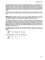
For example, consider an ADC card that has flowmeters attached to channels 2, 3, 4, and S~ and
thermocouples attached to channels 6 and 7. Say that you wanted to take the following sets of
re&dinas:
2
3
6
4
5
Pac.
t
.02
.02
.02
.02
.02
Galn
1
1
64
1
.02
1
Channel
64
To take these readings, you could set up the following arnys:
Channel
Pac.
Gain
2
.02
1
3
6
1
64
4
5
7
Update 3 (July 1988)
1-11
Vain. the Library
In taking read in,s from the channels in the channel array, the Random_lean subroutine will use the
pace array lix times and the aain array twice.
The call sequence to take thOle readinls once would be) in BASIC:
110
120
130
140
150
160
170
180
190
200
.320
330
.
INTEGER Channel(1:6)
REAL Pace(1:1)
INTEGER Ga1n(1:3)
REAL O8t.(1:6)
DATA 2,3,6.4.5,7
READ Channel(*)
DATA
READ
DATA
READ
.02
Pac.(*)
1,1,64
Galn(*)
Repeat=1·
Randoll_8ean("AOC U ,Channel(*),Data(*),Repeat,Pace(*),Galn(*»
Update 3 (July 1988)
1-12
Ulin, the Library
In Pascal the sequence would be:
CONST
name = ' ADC';
atart = 2;
atop = 7;
rapt = 1 ;
d size = 6;
p:size = 1 ;
g_aize = 3;
c size = 6;
TYPE
r_array = ARRAY (1 •• 6] OF real;
r_ptr = "'r_array;
i_array = ARRAY [1 •• 6] OF short int;
l_ptr = "'i_array;
VAR
data: r _ptr;
channel: i_ptr;
pace: r _ptr;
gain: i_ptr;
.
new(channel);
channel"'(1)
channel"'(2)
channel"'[3]
channel"'[4]
channel"'[5]
channel"'[6]
:=
:=
:=
:=
:=
:=
2;
3;
6;
4;
5;
7;
new(pace) ;
pace"'[1] := 0.02;
new(gain) ;
gain"'[1] := 1;
gain"'[2] : = 1;
ga1n'" [31 : = 64;
naw(data) ;
randOlt_8can. (n_.
c size.channel.
d:size.data.
rept.
p size.pace.
V:size.gain);
Update 3 (July 1988)
1-13
Using the Library
In the general case, the
Channel:
Pace:
Gain:
Data:
~th
read in, is taken using the following array elements:
chan array[i mod size of (chan array)]
pace-array[i mod size-of(pace-array»)
gain-array[i mod size:of(gain:array)]
dataTi]
Make sure that the data array is large enough to hold all of the readings that will be generated by the
Random_lean call. (Don't for,et to account for repeats.) As with Sequential_scan, if the call to
Random_lean abor~ the contents of the array will be undefined.
The channel, pace, and ,ain arrays must be dimensioned as arrays, even if they are only nn,le-valued.
Scalar variables can not be used.
The pace and gain values specified in Random_scan are used only for the duration of the
Random_lCan call. After the readinas have been taken, pace and ,ain revert to their previous values.
Special Considerations in Taking Readings
TimiDg of reading. Even thou,h the Measurement Library can take readin,. at the full 5S kHz
samplin, speed of the ADC card, it cantt return the results to your program that fast. The reason for this
is the IYItem overhead of BASIC or Pascal and the overhead of the Measurement Library itself. For any
aiven eet of readin,s the Measurement Library goes through the followinglteps:
a) Set up the card.
b) Take the readin.(.) at the specified pace rate.
c) Convert .the readings to the requested data format. (This includes checkin. the WAIT bit to make
sure there
a pacini error.)
waan'
The values below indicate the time required to process a reading equenu. The total time required is the
of item (a~ item (b), and the appropriate value from item (c). Note that these are 'Wont-cue values.
You would let these values from Series 200 computers usia, an 8 MHz MC68000 proceaor chip and no
floatin, point math card. Processina times will be shorter for ~mputen with later (futer) proceaor chips
and/or floating point math cards.
IUDl
BASIC
Inpul
I·
• Set-up time:
b) Read ti.e:
c) Data converelon time
BASE unite:
STANDARD unite:
USER unit.:
Sequential .ean
a) Set-up time:
b) Read time:
c) Data conversion time
BASE units:
STANDARD units:
USER units:
Update 3 (July 1988)
1-1.
2.0 ..sec
(pace interval) • (one reading)t
1 .0 IIsec
1.9 ...sec
2.5 msec
3.5 msec + 0.1 ....ee per reading
(pace interval) * (number of reading.)
0.3 msec per reading
1.2 msec per reading
1.5 msec per reading
Using the Library
RandOtn scan
a) Set-up time:
b) Read time:
c) Data conversion time:
BASE units:
STANDARD units:
USER units:
3.0 .sec + 0.4 Ileac per reading
(pace interval)
*
(number of readings)
1.3 msec per reading
2.2 msec per reading
2.4 msec per reading
PASCAL
Read channel
a) Set-up time:
b) Read time:
c) Data conversion ti.e
BASE units:
STANDARD units:
USER units:
Sequential scan
a) Set-up time:
b) Read time:
c) Data conversion time
BASE units:
STANDARD units:
USER units:
RandOll'l scan
a) Set-up time:
b) Read time:
c) Data conversion time
BASE units:
STANDARD units:
USER units:
2.0 msec
(pace interval)
* (one reading)t
I
1.0 msec
1.9 msec
2.2 Msec
3.4 Msec + 0.1 msec per reading
(pace interval) * (number of readings)
0.3 msec per reading
1.0 msec per reading
1.5 msec per reading
1.2 msec + 0.5 msec per reading
(pace interval)
*
(number of readings)
1.6 msec per reading
2.2 msec per reading
2.5 msec per reading
tNOTE: ''Input'' (BASIC) and "Read Channel" (Pascal) take one reading each time they
are called. Refer to page 2-9 of this manual.
Array size limits. The Measurement Library limits your maximum array size to 16,777,21 5 bytes. That's
really a hardware limit, imposed by the width of the address bus on HP 9000 Series 200 and Series 300
computers. At 8 bytes per reading that works out to a maximum of 2,097)1 SO readings from anyone call
to the Measurement Library, hardly a severe restriction. In practical terms, you will be limited by the size
of your physica.l memory long befor~ you run into the Measurement Library limit.
How your system lets you access that memory can be a different story. It)s no problem in a Pascal system,
since you can easily allocate an array large enough to take up all of your physical memory. Things are a
bit more subtle in BASIC, however.
At fint BASIC appears to limit you to 32767 readings from any single call to the Measurement Library,
Mce that's the largest number you can specify as an array dimension. But you can exceed that number of
readings by using a multi-dimensional array. You Can easily fill up all the memory you have using a
two-dimensional array. (BASIC allows you up to six dimensions in your arrays, 80 you can arrange your
data in whatever format is convenient.) The Measurement Library doesn't care if your array is
multi -dimensional; all it wants is the starting addre$S of the array (which you supply by passing the name
of the array in the subroutine call). The only thing you have to take care of is reading your data out of
the multi-dimensional array in the correct order.
Update 3 (July 1988)
I-IS
I
Vanl the Library
(Note that the ability to specify large data arrays does NOT constitute a continuous data acquisition
(CDA) scheme. The amount of data you can collect with the Measurement Library subn·utines is limited
by the amount of memory in your computer. The Measurement Library has no provision for. say. logging
hiBh-speed data to a disc for indefinite periods without missing readings.)
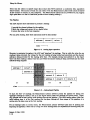
The Pipeline
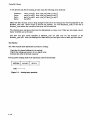
The ADC requires three operations to produce a readin,:
1) provide the channel address for the reading
2) latch the voltaae and convert it to a digital value
3) return the value to the host computer
For any liven reading, these three operations must be done serially:
+---------+---------+---------+
I address I convert I return I
+---------+---------+---------+
time ------->
FilUN 1-1. Analoa input operation
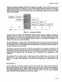
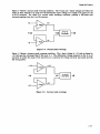
However, to maximize throughput. the ADC card "pipelines" the readings. That is, while the value for one
readinl il being returned, the voltage for the next reading is being latched and converted, and the channel
address i. bein, provided for the reading after that. For example, during time period t3 in the figure
below the fint readin, is taken. from the card while the second reading is being converted and the third
addr_ it beinllUpplied.
+---~------~+--~-----~-
I addr... 1 I convert 1
+-----------+----------I address 2 I
t1
t2
-----------+
2 I
-----------+-----------+
I convert 3 I return 3 I
-----------+-----------+----------+
I address 4 I convert 4 I r.turn 4 I
-----------+-----------+----------+
t4
t5
t6
I return
ti•• ---------------------------------------------------------)
Filure 1-2.. Ana10glnput Pipeline
To atart the flow of readings, the Measurement Library software primes the pipeline by taking two
··prbap" readings (at times tl and t2 in the figure above); these two readings are thrown away. (Their
only purpose was to Itart pulling valid readings through the pipeline.) The third reading taken is the first
valid readin., since it is the first reading that has gone through all three Itages of the pipeline; it is
written into the data array as the first reading.
For all readings taken in normal mode, the Measurement Library software takes care of priming and
emptyina the pipeline; it does this by ta.king two more readings than are requeated and throwing away the
Update 3 (July 1988)
1-16
Ualll the Library
two extn. aarbaae values. Thil happens for each IUbroutine call; you never have to pay any attention to
it, since the IOftware takes "re of it alL
(Note that since each subroutine call incun the extra. time required for two readinas, it is difficult (if not
impossible) to maintain accurate and even pacin, of readings between one subroutine call and the next If
your application requires accurate pacing for a block of readjngs, we suglest that you make all of those
readings with one subroutine call. Use Sequential_scan or Random_scan, as appropriate to your
applica tion. )
For readings taken in interrupt mode, the Measurement Library software does not take care of the
pipeline for you. You must keep track of which readings are which (not a very taxing operation) and
throw out the larba,e. More information on interrupt mode proaramming is contained later in this
.ection.
Overrange Errors
You can encounter two kinds of overrange conditions with the ADC card: normal mode overranle and
common mode overrange. Normal mode overrange occurs when the input voltage exceeds the ranae of
the analog-to-diaital converter. Common mode overrange occurs when either side of the differential
input voltaae exceeds the maximum input voltage of its input amplifier. The next several paragraphs
explain how these overrange conditions can affect your readings.
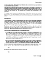
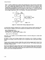
The voltage measured by the ADe card is the differential input voltage between the + Input and - Input
terminals of a channel on the card. The two sides of the input signal pass through separate input
amplifiers (op amps), a.nd are then sent to an analog-to-digital (A -to-D) converter for converSion to a
numeric value. (The figures below show this circuit confi,ured for a gain of 1.)
There are a couple of limitations that apply to this measurement circuit:
1) The voltage output from an input op amp can not exceed ± I 0 volts, relative to system ground. For a
gain of 1, this also means that the input voltage applied to the op amp can not exceed ± 10 volts.
again relative to system ground. (The situation gets rather more complicated for gains greater than
one; the formula for figuring the maximum input voltage is somewhat abstruse, involving various
voltages, gains, and a couple of 2s. We won't get into the mathematics of it, but figure 1-6 shows an
example of the results that you may see.) Exceeding this input limit causes a common mode
overrange: the output of the op amp is clipped at its limit (+10 volts or -10 volts) and the overrange
flag (the 0 bit in a base unit reading) is set to 1.
2) The A-to-D converter, which compares the outputs of the op amps, can not measure a difference of
more than 10 volts. If the difference between those outputs is more than 10 volts, the A-to-D
converter clips its output value to 10 volts; this situation is defined as a normal mode overrange.
The next few figures show various combinations of input voltages and the outputs they produce. In the
+ Input and - Input voltages (relative to system ground) are shown in "stickle type) like this:
figures~
+4
The differential input voltages are shown in Roman type, like this:
+6
Update 3 (July 1988)
1-17
Using the Library
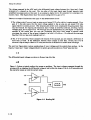
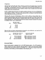
Figure 1- 3 shows a typical reading that causes no problems. The input voltages propagate through the
op amps with no clipping) the differential voltage is well within the range of the A-to-D converterJ and
the converter comes up with the correct value.
+4
---t
+4
+6
+6
A-to-O
Convert.,.
+6
-2
-2
---I
Figure 1-3. Reading OK
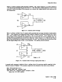
Figure 1- 4 shows a normal mode overrange condition. The + Input and - Input voltages are within the
range of their respective op amps) but the differential input voltage (+ 12 volts) is too great for the
A-to-D converter. The result is a normal mode overrange condition, yielding a full-scale (and
incorrect) reading from the A -to-D converter.
+6
---I
+6
+12
+12
A-to-O
Converter
-6
-6
---I
Figure 1-4. Normal mode overrange
Update 3 (July 1988)
1-18
+10
Using the Library
Fiaure 1-5 mows. common mode overran,e condition. The + Input voltage of + 12 volts is clipped to
+10 volts and the overrange fla, (0 bit) is set to L The differential voltale presented to the A-to-D
converter is within the range of the converter, 10 it converts the voltage correctly and comes up with
the wrong answer.
+1~---I
+10
A-to-O
+2
+4
Converter
+2
+8
+8
---I
Figure 1-5. Common mode overrange
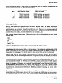
Figure 1-6 shows a subtler form of common mode overrange that you may encounter at gains greater
than 1. This is because the programmable gain amplifier amplifies the difference between the + Input
and -Input voltages before sending the result to the A-to-D converter. Even though the input
voltages appear to be acceptable, the amplifier may try to boost them out of the acceptable range. In
this case, the programmable pin circuit tries to boost the + Input voltage to 11. S volts, but the output
limit of the op amp keeps the voltage from exceeding +10 volts. The overrange flag (0 bit) is set to one
and the clipped voltage is sent to the A -to-D converter. The resulting value is incorrect.
+8---c
+6.5
+1
+7--....
+3.5
A-to-O
Converter
Gain
+6.6
=8
Figure 1-6. Common mode overrange at gain greater than 1
A normal mode overrange is indicated when a reading returns the maximum possible magnitude value.
(This is the same as "clipping".) The maximum magnitude value depends on the units in use, as follows:
Base: 409 S (all D bits set to 1)
Standard: (409S Isb - calibrate) / ,ain
User: «4095 lsb - calibrate) I pin) * multiplier + offset
where: Isb· 10 I 4095volts/bit
*
*
Update 3 (July 1988)
1-19
Using the Library
Note that it is not possible to tell the difference between a full scale reading and a normal mode
overrange reading.
By default, a normal mode overrange condition does not generate an error. However, by setting a
parameter in the Config_O call you can cause an error to be generated when a normal mode over range
occurs.
Common mode overranges are harder to detect than normal mode overranges. since the value of the
reading may appear to be correct even though an overrange has occurred. For this reason, common mode
over ranges are trapped as erron.
Note that the Measurement Library reports errors for normal mode and common mode overranges only
when you are operating in standard or user units. If you are operating in base units~ no error will be
reported. To detect a normal mode overrange in base units, check the 0 bits for a full scale reading; to
detect a common mode overrange, check the 0 bit
Pacing Errors
The pace counter on the ADC card is \lied to determine the duration of the sample portion of the sample
and hold cycle. The hold portion is always 9 microsecond., and the minimum sample portion is 9
microseconds. The Measurement Library lets you specify a pace interval that is the sum of these two time
periods. Thus you can set the pace at which readings are taken for ease in making accurate time domain
measurements of time-varying quantities.
If, due to outside facton (concurrent I/O transfers, keyboard interrupts, and 80 on), the Measurement
Library software is unable to read from the ADC card fast enough to keep up with a programmed pace
time, a pacing error will occur. This gives you the assurance that, in the absence of such errors, the time
domain measurements are being accurately paced.
While the ADC card and the Measurement Library are fully capable of taking readings every 18
microseconds, the variable gain input amplifiers on the card are not capable of slewing from maximum
positive to maximum negative during the 9 microsecond sample period that this pace rate requires. This
puts an upper limit on the lignal frequency component that the ADC can measure accurately at the 18
microsecond I8.mple rate. The following table shows that maximum frequency component for each gain,
for reading. to within llsb on a sinBle channel.
Gain
1
8
64
512
Update 3 (July 1988)
1-20
Maxilllum Signal
Frequency.Component
27
27
15
3.5
kHz
kHz
kHz
kHz
UIiq the Library
When more than one channel is being II.mpled (al in Sequential_1C8Jl and RandQDl_1CUl operatiolll) the
Jpeed of accurate ampling by the ADC is limited a. fonows:
Gain
1
8
64
512
Minimum Pace Ti... for
Multichannel Scans
50
50
71
1000
microseconds
microseconds
micro.econds
microseconds
Equivalent Ma)(iIlUM
Sa.pling Speed
20000
20000
14000
1000
readings
readings
readings
readings
per
per
per
per
second
second
second
second
Interrupt Mode
Interrupt mode operation is supported only in the BASIC language system. (It is NOT supported in
Pascal.) Interrupt mode is useful when you want your program to continue execution between readings
and still maintain an accurate or externally controlled pace rate. There are two subroutines associated
specifically with interrupt mode: Enable_intr and Disable_jntr. Appropriately enough, interrupt mode
is enabled by a call to Enable_intr and is disabled by a call to Disable_intr.
Only a limited subset of Measurement Library subroutine calls are allowed after you have entered
interrupt mode:
Input
Config_O
fnit
System_init
Disable_intr
Use of any other Measurement Library calls in interrupt mode will result in an error.
When you are in interrupt mode) the Measurement Library does not automatically take care of setting up
and clearing out the input pipeline. (Refer to the description of the analog input pipeline earlier in this
section.) Thus, when you take a reading with the Input subroutine, the result you get is the value of the
reading taken two readings ago. You should discard the data returned from the first two Input c;alls.
Interrupt mode does not handle multiple configurations of the same card cleanly. To avoid taking
erroneous readings, do not take readings from different configurations (names) for the same card while in
interrupt mode.
The shortest pacing interval usable in an interrupt mode application is dependent upon many factors. The
main factors Ire the speed of the CPU executing the BASIC program, and the type of BASIC program
instructions that are being executed while the ADC is taking readings. To properly undentand these
facton it is important to understand how the BASIC operating system services interrupts. When BASIC
hu been enabled to aervice interrupts for a specific select code with an "ON INTR IC, priority GOSUB
Jabel" statement and an interrupt occurs on that select code, BASIC logs the fact that the interrupt has
occurred, but does not execute the GOSUB until BASIC has completed executing the current BASIC
program line.
When using the ADC library in interrupt mode and an ADC interrupt has occurred, if the time to
complete the current BASIC program line, plus the time to execute the GOSUB, plus the time to execute
all the BASIC lines until the ADC library "Input" routine actually takes the reading from the ADC card
Update 3 (July 1988)
1-21
Using the Libtary
exceeds the pace interval time, the ADC library will return an error 857 indicating that a reading was
missed. Therefore the time to service the interrupt depends upon the BASIC program line that is
executing when the interrupt occurs as well as the code path to the ADC library "Input" routine.
For the faster interrupt servicing in BASIC. the following tips are offered:
1)
Make the ADC library l'lnput" routine the first statement in the interrupt service routine.
2)
Keep the interrupt service routine short. Remember that the pace interval period starts
with the "Input" routine. but cannot be serviced until the interrupt service routing
"RETURN" statement has been executed.
3)
Avoid BASIC instructions which take long times to execute like input/output operations or
matrix operations on large arrays.
4)
Avoid other interrupt processing at a higher priority than the ADC interrupt service
routine.
5)
Set the 98640A ADC card at the highest physical interrupt level possible (in this ca.se 6).
See the 98640A Reference Manual. HP part number 98640-90001, for details.
When using the interrupt mode it is important to determine experimentally that the pace interval being
used is compatible with the BASIC program instructions being executed while waiting for interrupts on
the particular computer family on which the program is executing.
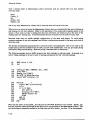
The following example shows a BASIC program that takes readings in interrupt mode. Its purpose is to
take 8 voltage readings; to do that it takes 10 readings and ignores the first 2 (invalid) readings.
.
40
SO
REAL Volts (-1:8)
1=2
110
120
130
o("ADC" • "98640AtI. 18, 1, .036)
Inlt(UADC")
Enable intr( "AOC")
ON INTR 18 GOSUB Service
Input("AOC",S.VoltsC-1»
140
150
340
350
360
.
Confi;
!
Service:
lt
It
Input( ADC .5.Volta(I-2»
1=1+1
IF 1>10 THEN
OFF INTR 18
370
380
390
400
410
Di8.ble intrC"AOC")
420
430
NEXT J
STOP
FOR J=1-TO 8
PRINT Volta (J)
440
450
460
END If:
RETURN
END
Update 3 (July 198 8)
1-22
Using the Library
Note that the order of the Enable_intr call and the ON INTR statement is not critical. Enable_intr
does not physically enable interrupts on the ADC card; it only sets flags in the Measurement Library. The
card interrupts are physically enabled by the first Input call after Enable_intr (line 1 SO in this example).
External Pacing
You might use external pacing for ADC readings if:
- - you want to use a pace interval longer than that allowed by the Measurement Library software
(0.0393336 second)
- - you want the readings to be controlled by an external event, rather than by time
External pacing is primarily a hardware operation. It is largely controlled by two hardware control lines.
IPACDA (internal pace disable) and EPCON (external pace control). There's not a lot of software
involvement. other than making the read requests that you would normally make for an internally paced
read. The timing of the execution of those read requests is controlled by the hardware. (There's no
provision in the IOftware for controlling IPACDA and EPCON directly; you'll ha.ve to build your own
circuits to control them.)
In the next leveral paralraphs we will look at some of the features of the hardware and software that
affect e1ternal pacing, and then we will see how they fit tdgether in external pacing applications. In this
manual we'll limit our discUllion of the hardware to telling you when the IPACDA and EPCON control
linea must be let low or high; we won't ,ive you instructions for building the circuits that control those
linea. You caD, however, ,et more information about thOle controllina from the ADC hardware manual,
part number 98640-90001.
Hardware Considerations
There are two control lines of interest for external pacing:
IPACDA determines whether the readinp are paced by the internal pacing timer on the ADC card. If
IPACDA illow, the internal pacing timer of the card is used; if IPACDA is high, the internal pacin.
timer is bJP8.Slled and readings are taken at the free run apeed of the. card (one readin, every 18
micrOleCOndt). Note that IPACDA must be hiah when readillli start in order for the timing of the firlt
reading of a series to be accurately known. (IPACDA can be set low after the start of readings if you
want the readings to be paced by the internal pacing timer.)
EPCON controls whether or not any readinp are taken. If EPCON is low, readings are taken whenever
they are requested. If EPCON ill high, requested readings are held off; a read request will not complete
until EPCON Joes low a,ain.
In summary, when EPCON is low, readings are taken at the free run speed of the card (if IPACDA i. high)
or at the time programmed into the internal pacing timer (if IPACDA is low). When EPCON is high,
readings stop.
Update 3 (July 1988)
1-23
Vain, the Library
Software Considerations
When making externally paced readings, you will have to allow for the software set-up time of the
various subroutines.
The eet-up times in the BASIC language for the reading subroutines are:
Input
Sequential scan
Random sean
2.0 millieeconds
3.5 milliseconds + 0.1 milliseconds per reading
3.0 .illi •• conde + 0.4 millis.conds per reading
Set-up times in Pascal are:
Read channel
Sequential lean
Random_scan
2.0 millis.conds
3.4 .illi •• conde + 0.1 millis.conds per reading
1.2 _illi •• conde + 0.5 millis.conds per reading
Application.
External pacing applications divide into two Jeneral types: single readings and bunts of readings.
Slplle readiDIS. The idea behind takiDa single externa.lly paced readings is that you keep EPCON high
until you want to take a reading, let it low only lona enou,h to take the reading) and then set it high
apin. The steps in taking a single readin, are:
1)
Set JPACDA high. IPACDA will remain high for the duration of externally paced readinas.
2)
Set £PeON hi,h. This holds off all read in,s.
3)
Issue a call to Input/read_channel, Sequentia1_ICI.~ or Random_scan.
4)
Wait. The length of time you wait Ihouldbe at least the set-up time.
S)
When it is time to take a readina, set EPCON low. Keep it low for 1 to 15 microseconds,
then set it hiah aga,in. This will allow one (and only one) readina to be taken.
6)
Repeat step 5 until you have taken all the readinls that you requested with the subroutine
call in step 3. The subroutine will return to your application proaram only after all
requested readinp have been taken.
AI indicated in Rep 4, each subroutine call you make requires that you wait the set-up time before
pulling the EPCON line to take the first reading. For Input (or Read_channel) calls made in normal
mod~ that means that you must wait the set-up time before each readina. If )'outre usina Input in
interrupt mode, the let-up time is required only before the first reading. Keep in mindt however, that the
EPCON pulses should be at least 36 milliRconds apart if you're operating in interrupt mode.
Update 3 (July 1988)
1-24
Using the Library
Bursts of Reading. The idea behind taking readinp in bursts is that you request multiple readings with
a subroutine call, and then take those readings in one burst by letting EPCON low until all of the readings
have been taken. These readings can be taken at the free run speed of the card, or they can be paced by
the card's internal pacing timer. The following steps are for triggering burst readings that are paced by
the internal pacillJ timer.
1)
Set IPACDA and EPeON high.
2)
Make a read request by issuing a call to Sequential_scan or Random_scan.
3)
Wait. You should wait for at least the set-up time plus the pace interval.
4)
Set the EPCON line low. The analoa-to-digital conversion for the fint read ina will start in
approximately 3 microseconds.
S)
Set the IPACDA line low. This must happen I to 1S microseconds after you aet £PCON
low.
Hold BPCON and IPACDA low until all of the requested readings have been taken. (The
lubroutine call will return to your application program after all of the readings have
completed)
6)
The requirement (in step 3) that you wait the set-up time plus the pace intervall.llUreI that the fint
reading occun at a more-or-Iess known time (within approximately 3 microseconds after EPCON is let
low). and that the voltage has been sampled for at least the prescribed sample time (pace interval minus 9
microseconds).
Combfnattou You Q.n combine the above two methods of external paeing if your application requires.
into thOle combinations here; we leave that u an exercise for the interested reader. The
We won't
methods above should give you enou,h information to make your combination work.
,0
Update 3 (July 1988)
1-25
The following' pages are replacement pages from the
previous update. Pages superseded by the current
update are not included.
PREFACE
Purpose: This manual explains how to use the HP 9864SA Measurement Library. It assumes that you
have a 'Working knowledge of the BASIC or Pascal language system on the HP 9000 Series 200 or Series
300 computen. It also assumes that you are generally fantiliar with the HP 98640A Analog-to-Digital
Converter card. (Refer to the manual for that card, HP part number 98640-90001, for more
information. )
OrpDUation: This manual is organized as follows:
Sec;tion 1:
How to use the HP 9864SA Measurement Library.
Sec;tion 2:
Alphabetica1li1tin, of Measurement Library subroutine calls.
Appendix A:
Error meaa,es.
Appendix II;
Quick reference guide to Measurement Library subroutine callsyntaL
Update 1 (November (985)
iii
I
CONTENTS
Section 1
USING THE LIBRARY
Introduction
0
0
0
•
Features. .
.
0
•
0
•••
•
•
Software Provided ...
•
•
•
0
0
••••••••••
•
0
0
0
••
The General Approach. . . . . . .
I
•
•
•
0
•
•
•
•
•
•
•
0
•
0
0
••••••••
•
•
0
•
•
•
•
•
•
•
•
•
0
••
0
•••••••••
•
•
•
•
•
•
•
•
0
•••••••••
0
•••••••••••
0
•••••••••
0
0
•
•
•
•
•
•
•
•
•
•
•
•
•
•
•
0
•
•
".
•
0
•
•
••
••••
Using BASIC 2. 1 . . . .
Uaing BASIC 3. 0, 4. 0 or So O. . .
General BASIC Programming . . . . . . . . . . . . . . . . . . . . . . . . . . . . . . . . .
Usin, Pascal 2.0. 2. I, 3.0, 3. I, or 3.2 ........
Writing the Program . . . . . . . . . . . . . . . . . . .
Settin, Up. . . .
Calibration . . . . . . .
Reporting Units ....
Error Reportinl and Handling. . . . . .
0
0
•
0
•
0
•
•
•
•
•
•
•
•
•
•
•
•
•
0
0
•
•
•
•
•
•
•
•
•
•
•
•
•
•
•
•
•
•
•
•
•
•
•
•
0
•
•
•
•
•
•
•
•
•
•
•
•
•
•
•
•
•
•
•
•
•
•
•
•
•
•
•
•
•
•
0
•
0
•••••••••••••••••
0
•
•
•
•
•
•
•
0
•
•
•
•
•
•
•
•
•
•
•
•
•
•
•
•
•
•
•
•
•
•
."
•
•
•
•
•
•
•
•
•
•
0
•••••••••••••••
•
•
•
•
." 0
0
•••••••
0
•••••
0
".
•
0
•
•
•
•
•
0
0
•••••••••
•••••••••••••••••
0
•
•
•
0
•
•
•
0
•
•
•
•
•
0
0
0
•••••••••
•
•
•
•
•
0
•
•
•
•
1-1
1-1
1-2
1-2
1-2
1-3
1-3
1-4
1- 5
1- 5
1-7
1-7
1-8
Multiple Confi,urations
1-8
Taking Readinp .
1-9
Special Considerations in Taking Readinas. . . . . . . . . . . . . . . . . . . . . . 1-14
The Pipeline . . . .
1-16
0
0
0
••
0
•••••••••••••••••••••••••••••
0
•
•
•
•
•
•
•
•
•
0
•
•
•
•
0
•
•
•
•
•
0
•
•
•
•
•
•
•
•
•
•
•
•
•
•
Overrange Errors. . . . . . . . . . . . .
Pacini Errors . . . . . . . . . . . . . . . . . . . .
0
Interrupt Mode. . . .
External Pacing...
0
0
•
•
•
•
•
•
•
•
•
•
•
•
•
•
•
•
•
•
•
•
•
•
•
0
•••
0
••
0
0
•
•
•
•
•
•
•
•
•
•
•
•
•
•
•
•
0
•
•
•
•
•
•
•
•
•
•
•
•
•
•
0
•
•
•
•
•
•
•
•
•
•
•
•
•
•
•
•
•
•
0
•
0
•••••••••••••••••
•
•
•
•
0
•••••••••••••••••
•
•
•
0
•••••••••••
•
0
0
•
•
0
0
•
•
.0
•
•
•
•••••••••••••••••••
Hardware Considerations ....
Software Considerations
Applications . . . . . . . . . .
•
•••
0
•••••••••••
•
0
0
•
•
•
•
•
•
•
•
•
•
•
•
•
0
••••••••••••
0
•••
0
••••••••••••
0
0
0
0
••••••••••
•
0
•
•
••
0
1-1 7
1-20
1-21
1-23
1-23
1-24
1-24
Section ~
SUBROUTINE INFORMATION
CALIBR.ATE . . . . . . . . . . . .
CONFIG_O
DISABLE_INTR .....
0
•••
0
•••••••••••
0
0
••••••••••
2-2
2-3
2-6
ENABLE_INTR . . . . . . . . . . . . . . . . . . . . . . . . . . . . . . . . . . . . . . . . . . 2-7
0
•••••
0
••••
0
0
••••••••
••••
0
0
•
0
••••••••••••
•••••••••••••••••••
0
•••
0
0
0
"• • • • • • • • •
•••
0
INIT . . . . . . . . . . . . . . . . . . . . . . . . . . . . . . . . .
INPUT . . . . . .
MEAS_LIB.__ INIT
RANDOM_SCAN ..
READ_CHANNEL . . . . . . . . . .
SEQUENTIAL_SCAN. . . . . . . . . . . . . . . . . . . . . . . . . . . . . . . . . . . . .
0
0
0
0
••••••••
0
•
0
0
0
•
00
0
•
•••••••••••
•••
0
0
0
0
••••••••••••••••••
••••••••••••
0
••••••••••••••••••
••••••••••••••••••••••
••••••••••••
0
••••••••
0
••
0
0
••••••••
•••••••••••••••
0
•••••••••••••••••••••••
0
0
•••
•
•
•
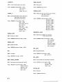
Appendix B
QUICK REFERENCE
0
•
•
•
•
•
•
•
•
•
•
•
•
•
•
•
•
•
•
•
•
•
•
•
•
.2-8
•••••••••••
0
0
0
••••
•
0
•
••••••••••••••
0
••
0
"0
0
Appendix A
MESSAGES
Update 2 (December 1987)
iv
••••••
•••
SET_GAIN. . . . . . . . . . .
0
0
0
0000
SET_UNITS.
" SYSTEM_INIT .
0
••
•
•
•
•
•
•
•
•
•
2-9
2-10
2-11
2-13
2-14
2-15
2-16
2 -1 7
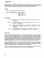
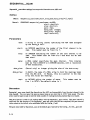
CONFIG_O
CoDfi&-O lets up an HP 98640A ADC card for access by the Measurement Library subroutines.
Syntax
BASIC:
Paecal:
Config O(name,Model[,.elect code[,galn[,
- pace[,report errorT,unita[,
.ultiplier[,off.et]]]]]]])
PROCEDURE config O(na.e: .tr255;
-
lIOdel: atr255;
•• lect code: .hor-tint;
gain: .hortlnt;
pace: real;
report error: .tr255.
units:-.tr255;
.ultiplier: re.l;
off.et: real);
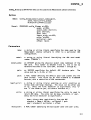
Parameter.
n... :
• • tring or .tring literal .pecifying the na... used by the
.....u ....nt Library .oftware to refer to a particular ADC
configuration.
lIOdel:
a .tring or .tring literal identifying the ADC card lIOdel
nu.ber ("88640A'·) •
• elect code:
an INTEGER giving the phy.ical .elect code (.dd,..•• ) of the
ADC card. Th i. nu.ber i. between 8 and 31, and i. .et by
h.rdware .witch•• on the card (SW1, .witche. 1 through 5).
,aln:
an INTEGER .pecifying the default ADC hardware gain.
value MUst be 1, 8, 84, or 512.
pace:
a REAL number defining the d.f.ult pace ti.. lo.ded into the
pace counter. This v.lue can be frOli 0.000018 to ·0.0393338
seconds, with. resolution of 600 nano.econds.
,..port_e~ror:
a .trlng or .tring lite,..l enabling an error condition on
nonaal mode overrange readings. The value can be either ye.
or no. (Only the 'ir.t character ie .ignificant; only "y"
and "V" are taken a. ye. t . all others indicate no.)
unit.:
a .tring or .tring literal _pacifying the unit. to u••d to
return ADC data. The unite can be baee. standard, or u.er.
(Only the first character ie significant.)
The
ba.e = binary data read directly f~ the ADC
standard • (ba••• ADClab - calibrate) I gain
u•• r • etandard • multiplier + offset
Multiplier:
a REAL number _pecifying the .ultlplier u_ed with us.r unit ••
1-3
CONFIG_O
offset:
a REAL number specifying the offset used with user units.
Default values:
select code
gain
pace
report error
units multiplier
offset
18
1
.001 second
no
standard
1.0
0.0
Dlacus.lon
Confi,_ 0 establishes a link between a name (which you supply) and an ADC card, and specifies operating
parameters for that name and card. Each ADC card used must be configured with a unique name. You
can configure the same card with several different names and parameter sets, and everything will work
except interrupt mode data transfers. DO NOT ATTEMPT TO ACCESS AN ADC BY ANOTHER NAME
DURING INTERRUPT MODE DATA TRANSFERS.
A maximum of 16 names may 'be configured into the Measurement Library software. If you need more
configurations, names may be re-used. If a name is identical to an already used name, all configuration
parameters for the old name will be erased and the new configuration parameters or defaults will be used.
The name will.then have to be reinitialized with Init before it is accessed.
All readings taken by the ADC are reported in one of three reporting units: base, standard, or user. Base
units are in the form of a 16-bit binary integer, with the following format:
15 14 13 12 11 10
9
8
7
6
5
4
3
2
1
o
+---+---+---+---+---+---+---+---+---+---+---+---+---+---+---+---+
I B I w I 0 I SiD I DID I 0 I DID I DID I 0 I 0 I DID I
+---+---+---+---+---+---+---+---+---+---+---+---+---+---+---+---+
MSB
LSB
where:
B· BUSY. If bit 15· 1, the ADC is busy. The reading is not taken and all other bits are invalid. If bit
15 • 0, a valid reading is returned.
I
W. WAIT. If bit 14. 1, the ADC card was in the wait state at the time of the reading. This means
that the card was not read within the interval lpecified in the pacing timer ~- that is, a paced read
was not made at ~he correct time. (Generally you will not see this bit let, since the ADC Library
softwa-re reports an incorrectly paced read as an error and will not return a value for the reading.)
o • OVERRANGE.
If bit 13· 0, a common mode overranle condition occurred during this reading,
and the readin, is invalid. If bit 13· I, no common mode overranle condition occurred during this
reading. Note that the sense of this bit is negative true.
S • SIGN. If bit 12. 0, the value returned for the reading is positive. If bit 12· 1, the value returned
for tbe read ina is negative.
Update 1 (November 1985)
2-4
INDEX
A
ADC card
calibration, 1-7
configuration, 1-5, 1- 8, 2 - 3
configurations, multiple, 1-8, 1-21, 2-4, 2-7
initialization, 1-5, 2-8, 2-17
input pipeline. 1 -16
readinls, 1-9
amplina speed, 1-1, 1-20
Analo, input pipeline, 1-16, 1-21
Array size limits, 1-15
B
Due units, 1-1, 1-7, 1-10, 2-4, 2-16
BASIC
common area, 1-5
error handlinl, 1- 8
estensions, 1-2
heap area, 1-5
interrupt mode, 1-21
loadiD, the Measurement Library subroutines, 1- 2, 1- 3
Meuurement Library subroutine size, 1- 3
parameter typinl. 1-3, 1-7, 2-5
pro.ramming, 1-2, 1-3, 1-5
c
Calibrate lubroutine, 1-7, 2-2, 8-2
Calibration, I-I, 1-5, 1-7, 2-2
Common area, 1- 5
Common mode overrange condition, 1-7, 1-8, 1-17, 1-19, 1-20, 2-4
Confi,uration of ADC cards, 1-5, 1-8, 2-3
Confil_O subroutine, 1-5, 1-7, I-a. 1-9. 1-10, 1-20, 1-21, 2-3, B-2
Control lines, IPACDA and EPCON, 1-23
CSUB packaae, 1-1
D
Data conversion times, 1-14
Disable_jntr subroutine, 1-21, 2-6, B-2
Update 2 (December 1987)
INDEX-I
,
Index
E
I
,
Enable_intr subroutine, 1-21, 2-7, B-2
EPCON control line, 1- 23
Error handling, 1- 8
Error messages, A-I
Error reporting, 1- 8
ERRN function, 1· 8
ESCAPECODE function, 1- 8
External pacing, 1- 2 3
G
Gain, 1-5, 1-6, 2-15
H
Heap area, 1-5
HP 147 51A package, 1-1, 1-9, 2-1
I
I
Initsubroutine, 1-5, 1-21,2-8,2-17, B-2
Initializing
ADC card, 1-5, 2-8, 2-17 .
Measurement Library, 1-5, 2-10
Input pipelin~ 1-16, 1-21
Input subroutine, 1-6, 1-9, 1-21, 2-7, 1-9, B-2
Interrupt mode, 1-1, 1-2, 1-3, 1-4, 1-10, 1-17, 1-11, 2-4,2-6,2-7,2-9
IPACDA control line, 1-13
L
Least significant bit (LSa) values, 2- S
Loading the Measurement Library subroutines, 1-1, 1-3
LSD values, 2- 5
M
Measurement Library
features, I-I
general information, 1-1
initialization, 1-5, 2-10
messages, A - 2
programming, 1-2
quick reference, B-1
size, 1- 3, 1-4
software provided, 1-2
subroutines, 1- 2, 1- 3
Update 2 (December 1987)
INDEX-2
Index
Meas_lib_init subroutine, 1-5, 2-10, 8-2
Messages, A-I
Multi -dimensional arrays, 1-1 5
Multiple configurations of an ADC card, 1-8, 1-21, 2-4, 2-7
N
Normal mode overranae conditio~ 1- S, 1- 8, 1-1 7, 1-1 8, 1-19
o
ON ERROR mechanism, 1-8
Overrange condition
~mmOD mode, 1-7, 1-8, 1-17, 1-19, 1-10. 1-4
normal mode, 1-5, 1-8, 1-1 7, 1- 18, 1-19
p
Pace interval, I - S, 1-6, 1-20
Pacina errors. 1-20
PacinI, external, 1-2 3
PaKal
common area, 1-5
error handlina. 1-8
heap area, 1-5
importin, tlae Measurement Library, 1-4
interrupt mode, 1-4, 1-21, 2-7
messal~ A-3
Meuurement Library size, 1-4
.parameter paainJ, 1-4
parameter typin" 1-4, 1-7. 2-1, 2-5
pro,rammina. 1-4. 1-5
Pipe) ine, 1-16, 1- 21
Programmin,
leneral, 1-2, 1- 5
in BASIC, 1-2, 1-3, 1-5
in Pascal, 1-4, 1-5
Q
Quick reference ,w.de, 8-1
R
Random_scan subroutine, 1-6, 1-9, I-II, 2-11, B-2
Readiop, timing of, 1-14
Read_channel subroutine, 1-6, 1-9, 2-9, 2-13,8-2
Reporting unit., 1-1, 1-5, 1-6, 1-7, 2-4, 2-16
Update 2 (December 1987)
INDEX-3
Index
s
I
Sampling speed, 1-1, 1-20
Sequential_scan subroutine, 1-6, 1-9, 1-10, 2-14, B-2
Set -up times, 1-14
. Setting
error reporting parameter, 1- 5
,ain, 1-5, 1-6
pace interval, 1- 5, 1-6
reporting units, 1-5, 1-6
Set_gain subroutine, 1-6, 1-10, 2-15, B-2
Set_units subroutine, 1-6, 1-7, 1-8, 2-16, B-2
Standard units, 1-1, 1-7, 1-8, I-20, 2-5, 2-16
Subroutine calls
Calibrate, 1-7, 2-2, B-2
Confil_O, 1-5, 1-7, 1-8, 1-9, 1-10, 1-20, 1-21, 2-3, B-2
Disable_intr, 1-21, 2-6, B-2
Enable_intr, 1-21, 2-7, B-2
Init, 1-5, 1-21, 2-8, 2-17, B-2
Input, 1-6, 1-9, 1-21, 2-7, 2-9, B-2
Meu_lib_init, 1-5, 2-10, B-2
Random_lCan, 1-6, 1-9, 1-11, 2-11, B-2
Read_channel, 1-6, 1-9, 2-9, 2-13, B-2
Sequential_scan, 1-6, 1-9, 1-10, 2-14, B-2
Set_lain, 1-6, 1-10, 2-15, B-2
Set_units, 1-6, 1-7, 1-8, 2-16, B-2
System_init, 1-5, 1-21, 2-17, B-2
System_initsubroutine, 1-5, 1-21, 2-17, B-2
T
Timing of readings, 1-14
Try-Recover mechanism, 1-8
u
Unit~ 1-1, 1-5, 1-6, 1-7, 2-4, 2-16
User units, 1-1, 1-7, 1-8, 1-20, 2-5, 2-16
Update 1 (November 198 S)
INDEX-4
HP Computer Systems
HP 98645A
Measurement Library
User's Manual
)1,
'il111
,I
,1: 'i
"I,
Flin-
HEWLETT
a:~ PACKARD
/'
III
I' ,"
,l,
'I'
"
1,1
", ~
<
,I
I
~1 I ~
..,..
I" \
',' .',
t,
j
I'
i,'
I
~!
'flI I' I~
'
,
I
"
: J
,
I: " t I
I'
,~
"
:,
rl3 HEWLETT
~~PACKAAD
Warranty Statement
Hewlett-Packard products are warranted against defects in
materials and workmanship. For Hewlett-Packard Desktop
Computer Division products sold in the U.S.A. and Canada,
this warranty applies for ninety (90) days from the date of
delivery. * Hewlett-Packard will, at its option, repair or replace
equipment which proves to be defective during the warranty
period. This warranty includes labor, parts, and surface
travel costs, if any. Equipment returned to Hewlett-Packard
for repair must be shipped freight prepaid. Repairs
necessitated by misuse of the equipment, or by hardware,
software, or interfacing not provided by Hewlett-Packard are
not covered by this warranty.
HP warrants that its software and firmware designated by HP
for use with a CPU will execute its programming instructions
when properly installed on that CPU. HP does not warrant
that the operation of the CPU. software. or firmware will be
uninterrupted or error free.
NO OTHER WARRANTY IS EXPRESSED OR IMPLIED.
INCLUDING. BUT NOT LIMITED TO. THE IMPLIED
WARRANTIES OF MERCHANTIBILITY AND FITNESS FOR
A PARTICULAR PURPOSE. HEWLETI-PACKAAD SHALL
NOT BE LIABLE FOR CONSEQUENTIAL DAMAGES.
*For other countries. contact your local Sales and Service
Office to determine warranty terms.
HP98645A
Measure.ment Libr,ary
User's Manual
ft:tl HEWLETT
.:e.
PACKARD
HEWLETT-PACKARD COMPANY
Roseville Networks Division
8000 Foothills Boulevat d
Roseville, California 95678
MANUAL PART NO. 98645-90001
E0684
Printed In U. s. A.
June 1984
PRINTING HISTORY
The Printing History below identifies the Edjtion of this M~nual and any Updates that are included.
Periodically, update packages are distributed which contaj!l replacement pages to be merged into the
manua~ including an updated copy of this Printing History page. Also, the update may contain write-in
instructions.
E8.ch reprinting of this manual will incorporate all past updates; however, no new information will be
added. Thus, the reprinted copy will be identical in content to prior printings of the same edition with
the user-inserted update information. New editions of this manual will contain new information, as well
as updates.
..Fir.st Edition .............................................. June 1984
NOTICE
The information contained in this document is subject to change without notice.
HEWLETT-PACKARD MAKES NO WARRANTY OF ANY KIND WITH REGARD TO THIS
MATERIAL, INCLUDING, BUT NOT LIMITED TO, THE IMPLIED WARRANTIES OF
MERCHANTABILITY AND FITNESS FOR A PARTIqULAR PURPOSE. Hewlett-Pac~ard shall not
be liable for errors contained herein or for incidental or consequential damages in connection with the
furnishing, performance or use of this rna terial.
This document contains proprietary information which is protected by copyright. All rights are
reserved. No part of this document may be photocQpied, reproduced or translated to another language
without the prior written consent of Hewlett-Packard Company.
Copyright 0 1984 by HEWLETT-PACKARD COMPANY
ii
PREFACE
Purpose: This manual explains how to use the HP 98645A Measurement Library. It assumes that you
have a working knowledge of the BASIC or Pascal language system on the HP 9 000 Series 200 computers.
It also assumes that you are generally familiar with the HP 98640A Analog-to-Digital Converter card.
(Refer to the manual for that card) HP part number 98640-90001 for more information.)
J
Organization: This manual is organized as follows:
Section 1:
How to use the HP 9864SA Measurement Library.
Section 2:
Alphabetical listing of Measurement Library subroutine c;alls.
Appendix A: Error messages.
Appendix B: Quick reference guide to Measurement LibrafY subroutine call1yntax.
iii
CONTENTS
Section 1
USING THE LIBRARY
Introduction ........................................................................................... 1-1
Features............................................................................................. 1-1
Software Provided................................................................................ 1-2
The General Approach.............................................................................. 1-2
Using BASIC 2. 1.................................................................................. 1-2
Using BASIC 3. O..•...........................................................•.•................. 1- 3
General BASIC Programming.................................................................. 1-3
Using Pascal 2. 0, 2. 1, or 3. O. . . . . . . . . . . . . . . . . . . . . . . . . . .. . . . . . . . . . . . . . . . . . . . . ... . . . . . .. . . . . . . . .. 1-3
Writing the Program................................................................................ 1-4
Setting Up.......................................................................................... 1-5
Calibration........ ........................ ....... .... .... . ..... .... ....... .......... ........... 1-7
Reporting Units. ............................................ ~ .•.......................... ~ . . .. 1-7
Error Reporting and Handling............................................................. 1-8
Multiple Configurations..................................................................... 1-8
Taking Readings.................................................................................. 1-9
The Pipeline.................................................................................. 1-14
Overrange Errors. ....... :................................................................... 1-1 5
Pacing Errors................................................................................. 1-1 9
Interrupt Mode.................................................................................. 1-19
External Pacing................................................................................. 1-21
Hardware Considerations. ................................................................. 1-21
Software Considerations................................................................... 1-21
Applications. ................................................................................. 1-22
Section Z
SUBROUTINE INFORMATION
CALIBRATE. ......................................................................................... 2-2
CONFIG _ O.......................................................................•.•.............•... 2- 3
DISABLE_ INTR. . . . . . . . ... . . . . . . . . . . . . . . . . . . . . . . . . . . . . . . . . . . . . . .. . . . . . . . . . . . . . . . . . . .. . . . . . . . . .. . . .. 2 - 6
ENABLE_INTR. .................................................................................... 2-7
INIT..................................................................................................... 2-8
INPUT.................................................................................................. 2-9
MEAS_LIB_INIT................................................................................ 2-10
RANDOM_SCAN................................................................................. 2-11
READ_CHANNEL............................................................................... 2-13
SEQUENTIAL_SCAN............................................................................ 2-14
SET_GAIN......................................................................................... 2-15
SET_UNITS........................................................................................ 2-l6
SYSTEM_INIT..................................................................................... 2-17
Appendix A
MESSAGES
Appendix B
QUICK REFERENCE
iv
~US_I_NG__T_HE__LI_B_RA_R_Y____________~lr~'
INTRODUCTION
The HP 9864SA Measurement Library provides a set of easy-to-use subroutines for taking readings from
the HP 98640A Analog-to-Digital Converter (ADC) card. These subroutines can be used from the BASIC
or Pascal language systems on the UP 9000 Series 200 computer. The subroutines are written in Pascal t
and are adapted to the DASIC language with the CSUB utility package. The Measurement Library is
compatible with BASIC 2. 1, BASIC 3.0, Pascal 2. 0, Pascal 2. 1, and Pascal 3. O.
The Measurement Library subroutine calls are a superset of the "HP 147 S 1A Computer Aided Test
Programming Package for the Model 6944A". BASIC programs written using the HP 1475 lA routines
should- be able to use the Measurement Library software with very little modification.
Features
The HP 9864SA Measurement Library allows you to:
Take a single reading from any of 8 channels at any of 4 gains.
Take readings by scanning across 1 to 8 channels, any number of times.
Take readings from channels in random order as specified in an address array. Optionally, you can
specify the gain and pace interval for each reading, and the readings can be repeated any number of
times.
ExpreSs readings in three different units:
Base units: binary integer returned from the ADC.
Standard units: base units adjusted for gain and calibration, expressed as real numbers.
User units: standard units times a user multiplier plus a user offset.
Take calibration (zero) readings on a specified channel, and apply that calibration adjustment to all
readings.
Re-set gain or units at any time.
Take readings at the full 5S kHz sampling speed of the ADC card from either BASIC or Pascal.
Take readings under interrupt mode in BASIC.
1-1
Using the Library
Software Provided
The HP 98645A Measurement Library includes these subroutine packages:
MEAS_LIB for use with BASIC 2.0
MEAS_LIB3 for use with BASIC 3.0
INTR2_1 for use with interrupt mode in BASIC 2. 1
MEAS_LIB.CODE for use with Pascal 2.0/2.1
MEAS_LIB3. CODE for use with Pascal 3.0
The software is provided on the following media:
Option 11630: 3-1/2" floppy disc
Option #655: 5-1/4" floppy disc
THE GENERAL APPROACH
The way you write programs using the Measurement Library is pretty much the same whether you use the
BASIC or Pascal language system. There are~ however, significant differences in the way you set up your
system environment. We will discuss these differences in the next few paragraphs.
Using BASIC 2.1
If you are using the BASIC 2.1 system, take the following steps to get your application up and running:
I) Boot up BASIC Z.O.
%.) Load the BASIC %,.1 extensions. The 2. I extensions are located on the Extended BASIC 2. 1 disc.
Insert that disc into the master drive and issue the command LOAD BIN "AP2_1".
3) Load the interrupt processing package if you will be taking readings in interrupt mode. (Interrupt
mode readings are discussed later in this section.) The interrupt processing package is located on the
Measurement Library disc. Insert that disc into the master drive and issue the command LOAD
BIN "INTR2_1".
4) Load any other BASIC extensions that you need for your application.
For example, this would be
the time to load Graphics 2. 1.
S) Write your BASIC program or load a previously written program into memory. In the paragraphs
below we will describe how to write your application program using the Measurement Library.
6) Load the Measurement Library subroutines if they are not already part of the program you wrote
in the previous step. The subroutines are located on the Measurement Library disc. Insert that disc
into the master drive and issue the command LOADSUB ALL FROM IIMEAS_LIB".
7)
1-2
RUD
your program. Debug as necessary (repeating steps 5 through 7).
Using the Library
Using BASIC 3.0 '
If you are using the BASIC 3. 0 system~ take the following steps to get your application up and running:
1) Boot up BASIC 3. O.
2) Load the BASIC 3.0 10 binary if you will be taking readings in interrupt mode. (Interrupt mode
readings are discussed later in this section.) The 10 binary is located on the BAStC 3.0 Language
Binary disc. Insert that disc into the master drive and issue the command LOAD BIN "10".
3) Load any other BASIC binaries that you need for your application. For example, this would be the
time to load graphics routines.
4) Write your BASIC program or load a previously written program into memory. In the paragraphs
below we will describe how to write your application program using the Measurement Library.
S) Load the Measurement Library subroutines if they are not already part of the program you wrote
in the previous step. The subroutines are located on the Measurement Library disc. Insert that disc
into the master drive and issue the command LOADSUB ALL FROM "MEAS_LIB3
11
•
6) Run your program. Debug as necessary (repeating steps 4 through 6).
General BASIC Programming
The Measurement Library subroutines add approximately
INTR2_1 binary adds approximately 1200 bytes.
23~700
bytes to your BASIC program. The
Note that integer parameters used in the Measurement Library subroutine calls must be explicitly typed as
INTEGER. (You can find out which parameters are integers by looking at the parameter descriptions in
the subroutine call listings in Section 2 of this manual.) Real parameters and string parameters (those
ending in $) need not be explicitly typed. Literal constants of any type (integer) real, or string) may be
used. Note that integers must not contain a decimal point.
You can invoke Measurement Library routines by calling them (CALL statement) or simply by entering
them by name. When you use them in an IF .. THEN statement or an ON .. statement~ the "CALLII
must be explicit.
Using Pascal 2.0, 2.1, or 3.0
You can call the Measurement Library subroutines from the Pascal language by importing the
Measurement Library and using the library subroutines as procedure calls with the syntax described in
Section 2 of this manual. Typically. you import the Measurement Library with a compiler directive of
$SEARCH 'MEAS_LIB'$
or
$SEARCH 'MEAS_LIB3'$
and an import statement of
1-3
Using the Library
IMPORT measurement_lib;
in your code. Importing the Measurement Library adds about 17600 bytes to your Pascal program.
If the Pascal system modules INTERFACE and 10 have not been merged into the system library file, you
will also have to include the compiler directive
$SEARCH 'INTERFACE.'.'IO.'$
Note that the
II. II
after each file name is significant.
The procedure calls for the Measurement Library are all exported from the file MEAS_LIB.CODE (or
MEAS_LIB3.CODE), along with the following types:
TYPE
shortint = -32768 .. 32767;
byte = 0 .. 255;
str255 = string[255];
iarraytype = ARRAY[O •• maxint] OF shortint;
rarraytype
ARRAY[O .• maxint) OF real;
rarraypt = . . rarraytype;
iarraypt = .... iarraytype;
=
Due to the rigorous structure of the Pascal language, you can't default parameters in the procedure calls.
However, to save you the bother of declaring real and integer arrays for the pace and gain array
parameters of the random_scan procedure, you can use the default pace or gain value (established by a
call to Con fig_ 0 or Set_gain) by specifying a 0 for the array size and a NIL for the array pointer. All
other parameters for all procedure calls must be explicitly provided in the procedure call as rea~ integer
(or shortint), or string variables, or as constants or literal constants. For all array parameters, make sure
that the array elements are of the correct type, real or shortint; do not substitute integer for mortint.
And take care that the size parameter you pass for an array does not exceed the actual size you declared
for that array. (If you exceed the declared array size, you can write all over the other variables in your
program, and cause yourself much anguish.)
Once your Pascal program has been written and compiled, it must be merged or linked to the
Measurement Library using the Pascal system librarian program. Be sure to transfer ALL the modules in
MEAS LIB or MEAS LIB3. If 10 is not in your system library file you will also have to transfer the
modul;JOCOMASM from the file 10 (found on your LIB: disc).
Interrupt mode operation is not supported in the Pascal environment. (That means we don't guarantee
that it will work. If you try it and it doesn't work, you can purchase consuJting services from, the nearest
HP sales and service office. See the back section of this manual for a list of sales and service offices.) An
interrupt service routine (ISR) is required for interrupt mode to work in Pascal, and we do not provide a
Pascal ISR with the Measurement Library. If you try to use interrupt mode in Pascal without a proper
ISR, you will probably crash your system. If you're an experienced PasCal programmer, you may be able to
write your own ISR. For more information on ISRs,refer to the Pascal 2.0 System Designer's Guide, part
number 09826-90074.
.
WRITING THE PROGRAM
In both BASIC and Pascal, writing your application program involves two major activities: setting up. the
card to take readings, and taking the readings. In addition, BASIC programs may take readings in
1-4
Using the Library
interrupt mode. We will cover these subjects in the paragraphs that follow. We will also say a few words
about externally paced readings.
All of the subroutine calls referred to below are described in .detail in Section 2 of this manual.
Setting Up
Setting up an ADC card for readings requires allocation of a common area) as well as calls to at least three
subroutines: Meas_Iib_init, Config_ 0, and Init.
The common area serves as the heap space for the subroutines in the Measurement Library. It is allocated
automatically in Pascal; in BASIC you must allocate it explicitly at the beginning of your program.
Reserve this area by including the following statement in your program:
20
COM/Heapcom/ INTEGER Heaparea(1:n)
where n is the size of the Heaparea array. The size of Heaparea is determined by the number of
configured names for ADC cards (more about that later) and the number of readings taken for calibration
(ditto). Use 53 integers for each ADC card configuration and 4 integers for each reading used in
calibration. We recommend using Heaparea(1: 1300); this allows all 16 possible ADC card configurations
and a calibration run of 100 readings.
In both BASIC and Pascal, the subroutine calls to Meas_lih_init, Config_ 0, and Init do the following:
Meas_lib_init initializes the Measurement Library, and must be called before any other subroutines in
the library are called. Meas_lib_init needs to be called only once in your program.
Confil_O sets up an ADC card for taking readings. At a minimum, you specify a name by which you
will call the card and the model number of the card. In addition, you can specify the select code of the
card, its gain, a pace rate for taking readings, an error reporting parameter for normal mode over range
errors, and the units (base, standard, or user) in which the readings will be reported. (Reporting units
are discussed below.) If you do not supply these optional parameters, Config_ 0 will supply default
values.
Init resets an individual card, disables interrupts for that card, and sets the calibration array for that
card to its default values. Init must be used before any other calls except Meas_lih_init, Config_O
and System_init. System_init is the same as Init, except that it initializes all cards that have been
configured.
l-S
Using the Library
The set-up portion of a typical BASIC program might look like this:
20
30
40
50
60
70
80
90
100
COM/Heapcom/ INTEGER Heaparea(1:1300)
INTEGER Select code, Gain
Name$=IIADC"
Model$="98640A
Select code=18
Gain=1Pace=0.01
Error$="No"
Un i t$="Standard"
220
230
240
Heas lib init
ConrTg O(Name$,Model$,Select code,Gain,Pace,Error$,Unit$)
Init(Name$)
-
II
The analogous Pascal code would look like this:
CONST
name = 'ADC';
model
'98640A';
select code = 18;
gain .-,;
pace = 0.01;
error = 'NO';
units = 'STANDARD';
multiplier = 1.0;
offset = 0.0;
=
BEGIN
meas lib init;
confIg O(name,model.select code,gain,pace,error,units,multiplier,offset);
init(name);
-
The most frequently used configuration parameters can be reset without reconfiguring the card; these
parameters are gain, pace interval, and units. The gain can be reset with a call to the Set_lain
subroutine, or a new gain can be specified as a parameter to the Input or Random_scan subroutine. (The
Input and Random_scan subroutines are used to take voltage readings from the ADC; they are described
later in this section.) A new pacing interval can be specified as a parameter to the Input,
Sequential_scan, or Random_scan subroutine. And the units can be reset with a call to the Set_units
subroutine. (Note that if you specify pace or gain parameters in an Input, Sequential_scan, or
Random_scan call, the specified pace or gain value holds only for the duration of the call; it reverts to its
previous value after the call completes.)
1-6
Using the Library
Calibration
Calibration gives you a way of compensating for offsets that are inherent to the ADC card. To use the
calibration feature) you must first reserve one of the channels on the card and short the + Input and
- Input terminals on that channel to card ground. Then use the Calibrate subroutine to take a specified
number of readings from that channel at a specified pace rate. The readings are taken at each of the gain
settings and the average at each gain is saved. These average readings are then used to calculate
correction values for positive and negative readings at each gain setting. When a subsequent reading is
taken on any of the other channels, the appropriate correction value is subtracted from the raw reading
before conversion to standard or user units.
Repol"ting Units
Reporting units come in three flavors: base, standard, and user; you specify one of these with the
Config_O or Set_units command. The units are:
Base units. Base units are in the form of a 16-bit binary integer, of which twelve bits represent the
magnitude of the reading. Readings reported in base units are raw readings; gain factors and
calibration corrections are not applied to base units. The format of a base unit reading is:
15 14 13 12 11 10
9
a 7 6 5 4 3 2
o
+---+---+---+---+---+---+---+---+---+---+---+---+---+---+---+---+
I B I W I 0 I SID I DID I 0 I DID I 0 I 0 I 0 I DID I 0 I
+---+---+---+---+---+---+---+---+---+---+---+---+---+---+---+---+
where:
B· BUSY. If bit 15 • 1, the ADC is busy. The reading is not taken and all other bits are invalid. If bit
1 S • 0, a valid reading is returned
w•
WAIT. If bit 14· I, the ADC card was in the wait state at the time of the reading. This means
that the card was not read within the interval specified in the pacing timer -- that is, a paced read
was not made at the correct time. (You should never see this bit sett since the ADC Library software
reports an incorrectly paced read as an error and will not return a value for the reading.)
o • OVERRANGE.
If bit 13· 0) a common mode overrange condition occurred during this reading,
and the reading is invalid. (Common mode overrange errors are discussed later in this section.) If bit
13 • 1) no common mode overrange condition occurred during this reading. Note that the sense of
this bit is negative true.
S. SIGN. If bit 12 • 0, the value returned for the reading is positive. If bit 12· I, the value returned
for the reading is negative.
.,
D. DATA. The data bits give the 12-bit binary magnitude of the voltage read from the ADC. (The
lign of the voltage is given by the S bit, bit 1 2. )
Note that all readings taken from the ADC card by the ADC Library software are returned to your
prOlram through real number parameten. This includes readings in base units. Thus, while the base
unit readings have integer values, they look like real numbers to your program until you explicitly
convert them to· integers. Assilning them to integer variables in BASIC. or using the trunc or round
function in Pascal, will make the oonvenion.
1-1
Using the Li brary
Standard units. Standard units are base units adjusted for gain and calibration, expressed as real
numbers. They are, in other words, volts.
User units. User units are standard units to which a user-specified multiplier and offset have been
applied, expressed as real numbers. You specify the values for the multiplier and offset in a Config_O
or Set_units subroutine call. (The default values for multiplier and offset yield standard unit values.)
You might use user units to change the units of your readings or to compensate for a known offset in
your readings, or both.
For example, say you were taking readings from a 4-to-20 rnA current loop transmitter connected to a
flow meter. Say further that the range of the flow meter was from 0 to 50 gallons per minute, and
that you were making your voltage readings across a 250-ohm resistor. That would mean that a
reading of 1. 0 volts corresponded to a flow rate of 0 gpm and that 5.0 volts corresponded to 50 gpm.
Using y-mx+b, you can derive a multiplier of 12. 5 and an offset of -12. 5, and specify these as
parameters to a Config_ 0 call.
180
Config_O("Flow","98640A",18,1,.01,"No","User",12.5,-12.5)
Then, whenever you take a reading from that current loop, the result is expressed directly in gallons per
minute. That's a lot easier than making a conversion from standard units every time you take a yoltage
reading.
Error Reporting and Handling
The Measurement Library reports errors for a variety of reasons. Typical errors include configuration
errors, pacing errors, and overrange errors. When such an error occurs, the Measurement Library forces a
system error and returns the error number. Your application program can trap and handle these errors
using the ON ERROR mechanism (in BASIC) or the Try-Recover mechanism (in Pascal). In BASIC, you
can get the error number with the ERRN function; in Pascal, use the ESCAPECODE function. (Certain
run time errors may be reported in BASIC as the Pascal error number plus 400. These errors are listed in
Appendix A.) If the errors are not trapped, your program will abort and the system will report the error.
The errors that can be returned by the Measurement Library are listed in Appendix A.
Note that one of the parameters of the Config_O subroutine determines whether normal overranges are
reported as errors or not. Note also that if you are using base units, no overrange errors -- either normal
or common mode -- are reported. (You can detect overrange conditions from the bits returned in base
unit format.) Overrange errors and pacing errors are discussed in more detail later in this chapter.
Multiple Configurations
The Measurement Library allows you to have up to 16 different ADC card configurations at anyone
time. Each configuration requires a separate call to Config_ 0, and each call specifies a unique name for
a card. You can assign multiple names, and thus multiple configurations, to a single card if you wish.
This would allow you to take readiIlgs from different voltage sources on different channels of the same
card without reconfiguring the card all the time. For example, say you had flow meters connected to
channels 1, 2, and 3 of the card and thermocouples connected to channels 4, 5, 6, and 7. You could
specify one name for a flow meter configuration and another name for a thermocouple configuration:
1-8
Using the Library
180
190
.
°
n
Con fig (Ur low" 9"98640A 918 t 1 , .01 t "No" , "User" 9 12.5, -12.5)
Config:O("Thermo" , 98640A", 18,64,.01 t "No", "Standard")
tl
When you want to take a reading from either type of voltage source, just specify the name of the
appropriate configuration in your reading call:
420
430
Input (IiThermo" ,5, Tvol t)
Input("Flow",2,Gpm)
If 16 different ADC configurations are not enough for your application, you can get more by re-using
existing names. Do this by making a call to Config_ 0 and specifying an existing name; the old
configuration parameters for that name will be erased and the new parameters (or their default values)
will replace them. You will then have to re-initialize the name with a call to the Init subroutine before
you can use the new configuration.
Note that the use of different names for the same ADC card will not work in interrupt mode. 00 NOT
ATIEMPT TO ACCESS AN ADC BY A DIFFERENT NAME DURING INTERRUPT MODE DATA
TRANSFERS.
"raking Readings
Taking readings is the whole reason for having an ADC card. Now that you've got your system
configured, it's time to start taking those readings. All readings from the ADC card are taken by three
subroutines: Input!Read_channel, Sequential_scan, and Random_scan. Here's how you use them:
Input/read channel Use the Input or Read_channel subroutine for taking a single reading from a
channel on the ADC card. Optionally) you can specify a gain and a pace interval in the subroutine call.
A call to Input would look like this in BASIC:
340
U
Input(UAOC ,Chan 9 Volts)
The analogous call to Read_channel would look like this in Pascal:
read_channel('ADC',ehan,volta,gain,paee);
Input is the name of the routine as used in a BASIC program; in a Pascal program, use Read_channel.
Input was chosen for BASIC for compatibility with the HP 14751A software. Note that you must be
very specific when you call the Input subroutine: the I must be upper case and all the other letters must
be lower case; otherwise there will be a conflict with the BASIC keyword INPUT. The name Input
doesn't work at all with Pascal (another keyword c;onflict). so Read_channel was chosen instead.
Whatever the name, the subroutine works the same way in either language.
1-9
Using the Library
Note that if you specify the optional parameters for gain and/or pace interval, they override the
existing values only for the duration of the subroutine call. After the call has completed, the gain and
pace interval parameters revert to their previous values.
The operation of the Input subroutine in interrupt mode is different from its normal operation. Refer
to the discussion of interrupt mode, later in this section, for more details.
Sequential scan. Use the Sequential_scan subroutine to take readings on all channels in sequence
from a starting channel to an ending channel. These readings are all taken at the same pace rate (which
you specify) and the same gain (specified by the most recent call to Config_O or Set_gain), and the
values are returned to a data array. Optionally, you can repeat the readings as many times as you want.
For example, if you wanted to take readings from channels 2 through 7 on an ADC card, at the same
gain and pace rate, Sequential_scan would be the appropriate subroutine to use. In BASIC:
100
110
INTEGER Start t StoPt Repeat
REAL Data(1:6)
230
240
250
260
270
Name$="AOC"
Start=2
Stop=7
Pace=O. 01
Rept-1
460
Sequential_scan(Name$tStarttStoPtPacetData(*)tRept)
.
In Pascal:
CONST
name -= 'ADC';
pace = 0.01;
start = 2;
atop = 7;
rept • 1
d size = 6;
TYPE
d array
ARRAY [1 •• 6]
d:ptr = ~d_array;
VAR
data: d_ptr;
=
or
real;
new(data);
••quential_scan(name t 8tart,8toPtpaee.d_8ize,data,rept);
..
1-10
Using the Library
You must make lure that your data array is large enough to hold all of the readings that the
Sequential_scan call will generate. Note that if the call to Sequential_scan aborts, the contents of the
array will be undefined. (This is because the Sequential_scan subroutine uses the array space as·
temporary storage for a variety of nasty, messy variables; it doesn't fill the array with nice, clean data
until just before it returns·to your program. If the subroutine aborts while the array space is filled with
garbage and your program tries to interpret the garbage as data, you may not be pleased with the
results. )
The pace interval that you specify when you call Sequential_scan will be maintained only for the
duration of that call. After the readings have been taken, the pace interval will revert to its previous
value.
Random scan. Use Random_scan when you need lots of flexibility. Random_scan lets you read
from the channels on a card in any order, and you can assign an individual pace interval and gain for
each reading. Additionally, you can repeat the set of readings as many times as you want.
The readings are controlled by a set of arrays. A channel array lists the order of the channels to be
read. A gain array lists the gains for the readings. A pace array lists the pace intervals that will elapse
between readings. And a data array stores the results. The sizes of the channel, pace, and gain arrays
need not be the same. The Random_scan subroutine simply starts at the beginning of each array and
uses the values in sequence. After Random_scan uses the last element in an array, it goes back to the
beginning of the array for the next value. (Note that the gain and pace values do not start over just
because the channel array repeats.)
For example, consider an ADC card that has flowmeters attached to channels 2, 3, 4, and 5, and
thermocouples attached to channels 6 and 7. Say that you wanted to take the following sets of
readings:
4
5
7
Pace
.02
.02
.02
.02
.02
.02
Gain
1
1
64
1
1
64
Channel
236
To take these readings, you could set up the following arrays:
Channel
2
Pace
.02
Gain
1
3
6
1
64
4
5
7
1-11
Using the Library
In taking readings from the channels in the channel array, the Random_scan subroutine will use the
pace array six times and the gain array twice. The call sequence to take those readings once would be,
in BASIC:
1-12
110
120
130
140
150
160
INTEGER Channel(1:6)
REAL Pace(1:1)
INTEGER Gain(1:3)
REAL Data(1:6)
DATA 2.3.4.5.6.7
READ Channel(*)
110
DATA .02
180
190
200
READ Pace(-)
READ Galn(*)
320
330
Random_Ican (" AOC" ,Channel (*) ,Data (*) ,Repeat t Pace (*) ,Gain (-) )
DATA 1.1,64
Repeat=1
Using the Library
In Pascal the sequence would be:
CONST
name = 'ADC';
start = 2;
stop = 7;
rept = 1;
d size = 6;
p-size = 1;
g-.ize = 3;
c-size = 6;
TYPE
r_array = ARRAY [1 •. 6] OF real;
r_ptr = ""r array;
i_array = ARRAY [1 •• 6] OF ahortint;
i_ptr = ""i_array;
VAR
data: r ptr;
channel: i_ptr;
pace: r ptr;
gain: i:ptr;
new(channel);
channel""[1]
2;
channel"" [2] .- 3;
channel"" [3] := 4;
channel"" [4] := 5;
channel"" [5] · 6;
channel""[S) .- 7;
new(pace) ;
pace"" [1] := 0.02;
new(gain);
ga1n""[1] .- 1 ;
ga1n"" [2] : = 1;
gain""[3] := 64;
·.-·..--
.-
new(data) ;
random scan (name,
c size,channel,
d:size,data,
rapt,
p size,p8ce,
g:size,gain);
1-13
Using the Library
In the general case, the ith reading is taken using the following array elements:
Channel:
Pace:
Gain:
Data:
chan array[i mod size of (chan array)]
pace-array[i mod size-of(pace-array)]
gain-array[i mod size:of(gain:array)]
data Ti]
Make sure that the data array is large enough to hold all of the readings that will be generated by the
Random_scan call. (Don't forget to account for repeats.) As with Sequential_scan, if the call to
Random_scan aborts, the contents of the array will be undefined.
The channel, pace, and gain arrays must be dimensioned as arrays, even if they are only single-valued.
Scalar variables can not be used.
The pace and gain values specified in Random_scan are used only for the duration of the
Random_scan call. After the readings have been taken, pace and gain revert to their previous values.
The Pipeline
The ADC requires three operations to produce a reading:
I) provide the channel address for the reading
2) latch the voltage and convert it to a digital value
3) return the value to the host computer
For any given
reading~
these three operations must be done serially:
+---------+---------+---------+
I address I convert I return I
+---------+---------+---------+
till. -------)
Filure 1-1. AnaJog input operation
1-14
Using the Library
However, to maximize throughput, the ADC card "pipelines" the readings. That is, while the value for one
reading is beinl returned, the voltage for the next reading is being latched and converted, and the channel
address is being' provided for the reading after that For example, during time period t3 in the figure
below the first reading is taken from the card while the second reading is being converted and the third
address is being supplied.
+-----------+----------I address 1 I convert 1 I
+-----------+----------I address 2' I
+---------t1
t2
-----------+
-----------+-----------+
I convert 3 I return 3
-----------+-----------+----------+
I address 4 I convert 4 I return 4 I
-----------+-----------+----------+
t4
t5
t6
I return·2
tiMe ---------------------------------------------------------)
Figure 1-2. Analog Input Pipeline
To start the flow of readings, the Measurement Library software primes the· pipeline by taking two
"garbagell readings (at times tl and t2 in the figure above); these two readings are thrown away. (Their
only purpose was to start pulling valid readings through the pipeline.) The third reading taken is the first
valid reading, since it is the first reading that has gone through all three stages of the pipeline; it is
written into the data array as the first reading.
For all readings taken in normal mode, the Measurement Library software takes care of priming and
emptying the pipeline; it does this by taking two more readings than are requested and throwing away the
two extra garbage values. This happens for each subroutine call; you never have to pay any attention to
it, since the software takes care of it all.
(Note that since each subroutine call incurs the extra time required for two readings, it is difficult (if not
impossible) to maintain accurate and even pacing of readings between one subroutine call and the next. If
your application requires accurate pacing for a block of readings, we suggest that you make all of those
readings with one subroutine call. Use Sequential_scan or Random_scan, as appropriate to your
application. )
For readings taken in interrupt mode, the Measurement Library software does not take care of the
pipeline for you. You must keep track of which readings are which (not a very taxing operation) and
throw out the garbage. More information on interrupt mode programming is contained later in this
section.
Overrange Errol'S
You can encounter two kinds of overrangc conditions with the ADC card: normal mode overrange and
common mode overrange. Normal mode overrange occurs when the input voltage exceeds the range of
the analog-to-digital converter. Common mode overrange occurs when either side of the differential
input voltale exceeds the maximum input voltage of its input amplifier. The next several paragraphs
explain how these overrange conditions can affect your readings.
1-15
Using the Library
The voltage measured by the ADC card is the differential input voltage between the + Input and - Input
terminals of a channel on the card. The two sides of the input signal pass through separate input
amplifiers (op amps), and are then sent to an analog-to-digital (A -to-D) converter for conversion tq a
numeric value. (The figures below show this circuit configured for a gain of 1.)
There are a couple of limitations that apply to this measurement circuit:
1) The voltage output from an input op amp can not exceed ±10 volts, relative to system ground. For a
gain of 1, this also means that the input voltage applied to the op amp can not exceed ± 10 volts,
again relative to system ground. (The situation gets rather more complicated for gains greater than
one; the formula for figuring the maximum input voltage is somewhat abstruse, involving various
voltages, gains, and a couple of 2s. We won't get into the mathematics of it, but figure 1-6 shows an
example of the results that you may see.) Exceeding this input limit causes a common mode
overrange: the output of the op amp is clipped at its limit (+ 10 volts or -10 volts) and the overrange
flag (the 0 bit in a base unit reading) is set to 1.
2) The A-to-D converter, which compares the outputs of the op amps, can not measure a difference of
more than 10 volts. If the difference between those outputs is more than 10 volts, the A-to-D
converter clips its output value to 10 volts; this situation is defined as a normal mode overrange.
The next few figures show various combinations of input voltages and the outputs they produce. In the
figures, + Input and - Input voltages (relative to system ground) are shown in "stick" type~ like this:
+4
The differential input voltages are shown in Roman type, like this:
+6
Figure 1-3 shows a typical reading that causes no problems. The input voltages propagate through the
op amps with no clipping, the differential voltage is well within the range of the A -to-D converter, and
the converter ~mes up with the correct value.
+4--~
+4
+8
+8
-2
-2
---t
Fiaure 1-3. Reading OK
1-16
A-to-D
Convert.,.
+6
Using the Library
Figure 1-4 shows a normal mode overrange condition. The + Input and - Input voltages are within the
range of their respective op amps, but the differential input voltage (+ 12 volts) is too great for the
A-to-D converter. The result is a normal mode overrange condition, yielding a full-scale (and
incorrect) reading from the A-to-D converter.
+6
+6
---4
+12
+12
. A-to-O
Converter
+10
-6
-6
---i
Figure 1-4. Normal mode overrange
Figure 1- S shows a common mode overrange condition. The + Input voltage of + 12 volts is clipped to
+10 volts and the overrange flag (0 bit) is set to 1. The differential voltage presented to the A-to-D
converter is within the range of the converter, so it converts the voltage correctly and comes up with
the wrong answer.
+1~---I
+10
+2
+4
A-to-O
Converter
+2
+8
+8
---4
Figure 1-5. Common mode overrange
1-17
Using the Library
Figure 1-6 shows a subtler form of common mode overrange that you may encounter at gains greater
than 1. This is because the programmable gain amplifier amplifies the difference between the + Input
and - Input voltages before sending the result to the A -to-D converter. Even though the input
voltages appear to be acceptable, the amplifier may try to boost them out of the acceptable range. In
this case, the programmable gain circuit tries to boost the + Input voltage to 11. 5 volts, but the output
limit of the op amp keeps the voltage from exceeding + 10 volts. The overrange flag (0 bit) is set to one
and the clipped voltage is sent to the A-to-D converter. The resulting value is incorrect.
+ 8 - -....
+6.5
+1
+7---1
+3.5
A-to-O
Convert.,.
Gain
+6.5
=8
Figure 1-6. Common mode overrange at gain greater than 1
A normal mode overrange is indicated when a reading returns the maximum possible magnitude value.
(This is the same as "clipping".) The maximum magnitude value depends on the units in use, as follows:
Base: 4095 (all D bits set to 1)
Standard: (4095 * Isb - calibrate) / gain
User: «4095 * lsb - calibrate) / gain) * mulitplier + offset
where: lsb· 10 / 4095 volts/bit
Note that it is not possible to tell the difference between a full scale reading and a normal mode
overrange reading.
By default, a normal mode overrange condition does not generate an error. However, by setting a
parameter in the Config_ 0 call you can cause an error to be genera ted when a normal mode overrange
occurs.
Common mode overranges are harder to detect than normal mode overranges, since the value of the
reading may appear to be correct even though an overrange has occurred. For this reason, common mode
overranges are trapped as errors.
Note that the Measurement Library reports errors for normal mode and common mode overranges only
when you are operating in standard or user units. If you are operating in base units, no error will be
reported. To detect a normal mode overrange in base units, check the D bits for a full scale reading; to
detect a common mode overrange. check the 0 bit.
1-18
Using the Library
Paeing Errors
The pace counter on the ADC card is used to determine the duration of the sample portion of the sample
and hold cycle. The hold portion is always 9 microseconds, and the minimum sample portion is 9
microseconds. The Measurement Library lets you specify a pace interval that is the sum of these two time
periods. Thus you can set the pace at which readings are taken for ease in making accurate time domain
measurements of time-varying quantities.
If,due to outside factors (concurrent I/O transfers, keyboard interrupts, and so on), the Measurement
Library software is unable to read from the ADC card fast enough to keep up with a programmed pace
time, a pacing error will occur. This gives you the assurance that, in the absence of such errors) the time
domain measurements are being accurately paced.
While the ADC card and the Measurement Library are fully capable of taking readings every 18
microseconds, the variable gain input amplifiers on the card are not capable of slewing from maximum
positive to maximum negative during the 9 microsecond sample period that this pace rate requires. This
puts an upper limit on the signal frequency component that the ADC can measure accurately at the 18
microsecond sample rate. The following table shows that maximum frequency component for each gain,
for readings to within I lsb on a single channel.
Gain
1
8
64
512
Maximum Signal
frequency Component
27
27
15
3.5
kHz
kHz
kHz
kHz
When more than one channel is being sampled (as in Sequential_scan and Random_scan operations) the
speed of accurate sampling by the ADC is limited as follows:
Gain
1
8
64
512
Minimum Pace Time for
Multichannel Scans
50 microseconds
50 microseconds
71 microseconds
1000 microseconds
Equivalent Maximum
Sampl ing Speed
20000
20000
14000
1000
readings
readings
readings
readings
per
per
per
per
second
second
second
second
Interrupt Mode
Interrupt mode operation is supported only in the BASIC language system. (It is NOT supported in
Pascal.) Interrupt mode is useful when you want your program to continue execution between readings
and still maintain an accurate or externally controlled pace rate. There are two subroutines associated
specifically with interrupt mode: Enable_intr and Disable_intr. Appropriately enough, interrupt mode
is enabled by a ca.ll to Enable_intr and is disabled by a call to Disable_intr.
1-19
Using the Library
Only a limited subset of Measurement Library subroutine calls are allowed after you have entered
interrupt mode:
Input
Config_O
Init
System_init
Disable_intr
Use of any other Measurement Library calls in interrupt mode will result in an error.
When you are in interrupt mode, the Measurement Library does not automatically take care of setting up
and clearing out the input pipeline. (R.efer to the description of the analog input pipeline earlier in this
section.) Thus, when you take a reading with the Input subroutine, the result you get is the value of the
reading taken two readings ago. You should discard the data returned from the first two Input calls.
Interrupt mode does not handle multiple configurations of the same card cleanly. To avoid taking
erroneous readings, do not take readings from different configurations (names) for the same card while in
interru pt mode.
The shortest recommended pacing interval in interrupt mode is 36 milliseconds. This is very close to the
longest pacing interval available from the ADC card (39. 3336 milliseconds). You can get longer pacing
intervals by using external pacing. (External pacing is discussed later in this section.)
The following example shows a BASIC program that takes readings in interrupt mode. Its purpose is to
take 8 voltage readings; to do that it takes 10 readings and ignores the first 2 (invalid) readings.
40
50
REAL Volta (-1:8)
110
120
130
140
150
Config 0("AOC". 98640A u .18,1,.036)
Init(ttADC")
Enable intr(ItAOC
ON INTR 18 GOSUB Service
Input("ADC .S,Volta(-1»
340
Service:
,
InputC"AOC".5.Volts(I-2»
350
1=2
.
1I
U
)
II
360
1=1+1
370
IF 1>10 THEN
OFF INTR 18
Disable intr("AOC
PRINT Volta(1:8)
STOP
END IF"
RETURN
380
390
400
410
420
430
440
U
)
END
Note that the order of the Enable_intr call and the ON INTR statement is not critical. Enable_intr
does not physically enable interrupts on the ADe card; it only sets flags in the Measurement Library. The
card interrupts are physically enabled by the first Input call after Enable_intr (line 1SO in this example).
1-20
Using the Library
External Pacing
You might use external pacing for ADC readings if:
-- you want to use a pace interval longer than that allowed by the Measurement Library software
(0.0393336 second)
-- you want the readings to be controlled by an external event, rather than by time
Exte.rnal pacing is primarily a hardware operation. It is largely oontrolled by two hardware control lines,
IPACDA (internal pace disable) and BPCON (external pace control). There's not a lot of software
involvement, other than making the read requests that you would normally make for an internally paced
read. The timing of the execution of those read requests is controlled by the hardware. (There's no
provision in the software for controlling IPACDA and EPCON directly; you'll have to build your own
circuits to control them.)
In the next several paragraphs we will look at some of the features of the hardware and software that
affect external pacing, and then we will see how they fit together in external pacing applications. In this
manual we'll limit our discussion of the hardware to teliing you when the IPACDA and EPCON control
lines must be set low or high; we won't give you instructions for building the circuits that control those
lines. You can, however, get more information about those control lines from the ADC hardware manual,
part number 98640- 9000 1.
Hardware Considerations
There are two control lines of interest for external pacing:
IPACDA determines whether the readings are paced by the internal pacing timer on the ADC card. If
IPACDA is low, the internal pacing timer of the card is used; if IPACDA is high, the internal pacing
timer is bypassed and readings are taken a t the free run speed of the card (one reading every 1 8
microseconds). Note that IPACDA must be high when readings start in order for the timing of the first
reading of a series to be accurately known. (IPACDA can be set low after the start of readings if you
want the readings to be paced by the internal pacing timer.)
EPCON controls whether or not any readings are taken. If EPCON is low, readings are taken whenever
they are requested. If EPeON is high, requested readings are held off; a read request will not complete
un til EPCON goes low again.
In summary, when EPCON is low, readings are taken at the free run speed of the card (if IPACDA is high)
or at the time programmed into ·the internal pacing timer (if IPACDA is low). When EPeON is high,
readings stop.
Software Considerations
When making externally paced readings, you will have to allow for the software set-up time of the
various subroutines. The set-up times in the BASIC language for the reading subroutines are:
Input
Sequential_sean
2.0 milliseconds
3.5 milliseconds + 0.1 milliseconds per reading
1-21
Using the Library
Random scan
3.0 milliseconds + 0.4 milliseconds per reading
You can use these set-up times for Pascal programming as well. Pascal set-up times are shorter than
those "in BASIC, so the times listed above will give you plenty of margin in your Pascal applications.
Applications
External pacing applications divide into two general types: single readings and bursts of readings.
Single readings. The idea behind taking single externally paced readings is that you keep EPCON high
until you want to take a reading, set it low only long enough to take the reading, and then set it high
again. The steps in taking a single reading are:
I) Set IPACDA high. IPACDA will remain high for the duration of externally paced readings.
2) Set EPCON high. This holds off all readings.
3) Issue a call to Input/read_channel, Sequential_scan, or Random_scan.
4) Wait. The length of time you wait should be at least the set-up time.
S) When it is time to take a reading, set EPCON low. Keep it low for I to 1S microseconds, then set it
high again. This will allow one (and only one) reading to be taken.
6) Repeat step S until you have taken all the readings that you requested with the subroutine call in
step 3. The subroutine will return to your application program only after all requested readings have
been taken.
As indicated in step 4, each subroutine call you make requires that you wait the set-up time before
pulsing the EPCON line to take the first reading. For Input (or Read_channel) calls made in normal
mode, that means that you must wait the set-up time before each reading. If you're using Input in
interrupt mode, the set-up time is required only before the first reading. K.eep in mind, however, that the
EPCON pulses should be at least 36 milliseconds apart if youJre operating in interrupt mode.
Bursts of Readings. The idea behind taking readings in bursts is that you request multiple readings with
a subroutine call, and then take those readings in one burst by setting EPCON low until all of the readings
have been taken. These readings can be taken at the free run speed of the card, or they can be paced by
the card's internal pacing timer. The following steps are for triggering burst readings that are paced by
the internal pacing timer.
1) Set IPACDA and EPCON high.
2) Make a read request by issuing a call to Sequential_scan or Random_scan.
3) Wait. You should wait for at least the set-up time plus the pace interval.
4) Set the EPCON line low. The analog-to-digital conversion for the first reading will start in
approxima tely 3 microseconds.
S) Set the IP ACDA line low. This must happen 1 to IS microseconds after you set BPeON low.
6) Hold EPeON and IPACDA low until all of the requested readings have been taken. (The subroutine
call will return to your application program after all of the readings have completed.)
1-22
Using the Library
The requirement (in step 3) that you wait the set-up time plus the pace interval assures that the first
reading occurs at a more-or-Iess known time (within approximately 3 microseconds after EPCON is set
low), and that the voltage has been sampled for at least the prescribed sample time (pace interval minus 9
microseconds).
Combinations. You can combine the above two methods of external pacing if your application requires.
We won't go into those combinations here; we leave that as an exercise for the interested reader. The
methods above should give you enough information to make your combination work.
1-23
'----SU_B_.R_O_U_T_IN_E_I_NF_O_R_M_A_T_IO_N_ _ _ _
---'I~I!III,
This section gives the subroutine call syntax for the subroutines in the HP 9864SA Measurement Library.
The subroutine calls supported by the library are:
Calibrate **
Config_O **
Disa ble_intr
Enable_intr *
Init
Input
Meas_lib_init **
Random_scan
Read_channel
Sequential_scan
Set_gain **
Set_units **
System_init
*
*
* These
calls incorporate optional extensions beyond the HP 147 SlA Computer Aided Test
Programming Package for the Model 6944A).
** These calls do not exist in the HP 147 51 A package.
In the following subroutine descriptions, these conventions apply:
-- The parameters list for the subroutine appears in parentheses: ( ). These parentheses must be
included in the subroutine call
-- Optional parameters (BASIC only) are contained within square brackets: [ ].
String parameters for name and model number are case sensitive. (That is, don't use lower case characters
in place of upper case, and vice versa.) All other string parameters are case insensitive.
Note that none of the parameters in Pascal calls are optional.
Pascal data types exported by the Measurement Library are as follows:
TYPE
shortint = -32768 •. 32767;
byte = O.. 255;
str2S5 = string[25S];
iarraytype = ARRAY[O .• maxint] OF shortint;
rarraytype = ARRAY[O .. maxint] OF real;
rarraypt = "'rarraytype;
iarraypt
"'iarraytype;
=
The remainder of this section gives the subroutine call syntax, arranged by subroutine in alphabetical
order. Note that parameters identified as INTEGER are of type INTEGER in BASIC, but of type shortint
in Pascal.
2-1
CALIBRATE
Calibrate allows you to measure and compensate for the various offsets in the ADC card. To do this,
Calibrate dedicates one channel on the card to making reference readings; the offsets derived from the
reference readings are used to adjust the readings taken on the remaining channels of the card.
Syntax
BASIC: Calibrate(name,channel,pace,number)
Pascal: PROCEDURE calibrate(name: str25S;
channel: shortint;
pace: real;
number: short int) ;
Parameter.
name:
a string or string literal specif"ying the ADC name froll the
Config_O call.
channel:
an INTEGER specifying the reference channel (from 0 to 7) to
be used for calibration.
pace:
a REAL nUllber specifying the calibration pace rate, froll
0.000018 to 0.0393336 seconds with a resolution of 600
nanoseconds.
number:
an INTEGER specifying the number of readings to be taken for
this calibration. This number must be from 1 to 32767.
Discussion
To use the calibration feature, you must first short the + Input and - Input terminals of one of the
channels on the card to card ground; this gives a 0 volt input for that channel. Then you specify that
channel in the call to the Calibrate subroutine. When the Calibrate call is executed, the specified number
of readings are taken at all gain settings, and the average for each gain setting is saved. The offsets are
then used to calculate the proper correction values for positive and negative readings at each gain. When
subsequent readings are taken on other channels, the correction value is subtracted from the reading prior
to conversion to standard or user units. (No correction is applied to a reading expressed in base units.)
Note that occasionally a Calibrate call will abort with an error 860. This may be caused by temporary
transient electrical noise, especially on calibration calls with small numbers of readings. 860 errors from
Calibrate calls should routinely be re-tried several times, and the connections of the shorting wires at the
calibration channel checked, before you assume that the ADC card is defective.
Note that Calibrate temporarily requires 8 bytes of memory for each reading specified in the number
parameter. Large numbers of readings may cause errors due to not enough memory.
2-2
Confil_O sets up an HP 98640A ADC card for access by the Measurement Library subroutines.
Syntax
BASIC:
Pascal:
Config O(name,model[,select code[,gain[,
- pace[.report errorT,units[.
multiplier[.offset]]]]]]])
PROCEDURE config OCneme: str255;
- model: str255;
select code: shortint;
gain: shortint;
pace: real;
report error: str255;
units: -str255;
multiplier: real;
offset: real);'
Parameters
·name:
a string or string literal specifying .the name used by the
Measurement Library software to refer to a particular ADC
configuration.
model:
a string or string literal identifying the ADC card model
numb. r ("98640A").
select code:
an INTEGER giving the physical select code (address) of the
ADC card.
This number is between 8 and 31, and is set by
hardware switches on the card (SW1, switches 1 through 5).
gain:
an INTEGER specifying the default ADC hardware gain.
value must be " 8. 64, or 512.
pace:
a REAL number defining the default pace time loaded into the
pace counte r. Th i s va lue can be from 0.000018 to 0.0393336
seconds, with a resolution of 600 nanoseconds.
report_error:
a string or string literal enabling an error condition on
nonnal mode overrange readings. The value can be either yes
or no.
(Only the first character is significant; only "y"
and "y" are taken as yes, all others indicate no.)
units:
a string or string literal specifying the units to used to
return ADC data. The units can be base, standard, or user.
(Only the first character is significant.)
The
base = binary data read directly from the ADC
standard = (base * AOClsb - calibrate) I gain
user = standard * multiplier + offset
multiplier:
a REAL number specifying the multiplier used with user units.
2-3
CONFIG
0
offset:
a REAL number specifying the offset used with user units.
Default values:
select code
gain
pace
report error
units multiplier
offset
18
1
.001 second
no
standard
1 .0
0.0
Discussion
Config_O establishes a link between a name (which you supply) and an ADC card, and specifies operating
parameters for that name and card. Each ADC card used must be configured with a unique name. You
can configure the same card with several different names and parameter sets, and everything will work
except interrupt mode data transfers. DO NOT ATTEMPT TO ACCESS AN ADC BY ANOTHER NAME
DURING INTERRUPT MODE DATA TRANSFERS.
A maximum of 16 names may be configured into the Measurement Library software. If you need more
configurations) names may be re-used. If a name is identical to an already used name, all configuration
parameters for the old name will be erased and the new configuration parameters or defaults will be used.
The name will then have to be reinitialized with Init before it is accessed.
All readings taken by the ADC are reported in one of three reporting units: base, standard, or user. Base
units are in the form of a 16-bit binary integer, with the following format:
15 14 13 12 11 10
9
8
1
6
5
4
o
3
2
+---+---+---+---+---+---+---+---+---+---+---+---+---+---+---+---+
I B I
I 0 I 5 I 0 I DID I 0 I 0 I DID I DID I DID I 0 I
+---+---+---+---+---+---+---+---+---+---+---+---+---+---+---+---+
w
MSB
lSB
where:
B == BUSY. If bit 15 == 1, the ADC is busy. The reading is not taken and all other bits are invalid. If bit
15· 0, a valid reading is returned.
w • WAIT.
If bit 14· 1, the ADC card was in the wait state at the time of the reading. This means
that the card was not read within the interval specified in the pacing timer -- that is, a paced read
was not made at the correct time. (You should never see this bit set, since the ADC Library software
reports an incorrectly paced read as an error and will not return a value for the reading.)
o • OVERRANGE.
If bit 1 3 == 0. a common mode overrange condition occurred during this reading,
and the reading is invalid. If bit 13 == 1, no common mode overrange condition occurred during this
reading. Note that the sense of this bit is negative true.
S • SIGN. If bit 12 • 0. the value returned for the reading is positive. If bit 12· 1, the value returned
for the reading is negative.
2-4
CONFIG_O
D· DATA. The data bits give the 12-bit binary magnitude of the voltale read from the ADC. (The
sian of the voltage is given by the S bit, bit 12.)
MSB • most significant bit.
LSB • least significant bit.
Base unit readings are raw readings; no gain factors or calibration corrections are applied.
The value used by the Measurement Library for the ADC card least significant bit (ADelsb) is the 64-bit
floatina point value of
10 volts / 409 S bits
or
2. 442002442002442 millivolts per bit
The least significant bit (LSB) values used in each gain range are:
LSB • ADClsb / gain
Thus, the 'approximate LSD values in each gain range are:
Gain
1
8
64
512
LSB
2.4420
305.25
38.156
4.7695
millivolts
microvolts
microvolts
microvolts
Standard units are real numbers representing true volts. They are equivalent to base unit values corrected
for gain and calibration (if any). User units are real numbers equivalent to standard units times a
multiplier plus an offset.
ADC readings are always returned from the Measurement Library calls as real numbers or real array
elements (IEEE 64 bit floating point binary representation in both BASIC and Pascal). Readings in
standard or user units should be stored and manipulated as real numbers. Readings in base units must be
converted into integer format by the user program prior to any manipulation of the data. Assignment to
an integer variable in BASIC, or using the trunc or round function in Pascal, will suffice.
Refer to ''Setting Up" in Section 1 of this manual for a full discussion of ADC card configuration.
2-5
DisabJe_intr configures the ADC card for normal, non-interrupt mode operation.
Syntax
BAS Ie: 0 i sa b I e _ in t.r ( name)
Pascal: PROCEDURE disable_intr(name: str255);
Parameter
name:
a string or string literal specifying the ADC name assigned
by the Confi9_0 call.
Discussion
Interrupt mode operation is supported only for BASIC environments. Use of interrupt mode in Pascal is
not supported. Please refer to the discussion of the Enable_intr subroutine (next page) for further
information.
2-6
Enable_intr configures an ADC card for interrupt mode operation.
Syntax
BASIC: Enable_intr(name)
Pascal: PROCEDURE enable_intr(name: str25S);
Parameter
name:
a string or string literal specifying the ADC name assigned
by the Config_O call.
Discussion
Interrupt mode operation is not supported in the Pascal environment. (That means you're on your own if
you use it. If you have trouble making it work, you can purchase HP consulting, on a time and materials
basis, from your local HP sales and service office. HP sales and service offices are listed in the back of this
manual.) For interrupt mode to work in Pascal, you need to have an appropriate interrupt service routine
(ISR). If you use interrupt mode without one, you will probably crash your system. We don't provide an
ISR as part of the Measurement Library, but if you're a skilled Pascal programmer you may be able to
write one of your own. Refer to the Pascal 2.0 System Designer's Guide, part number 09826-90074, for
more information on ISRs.
Interrupt mode does work in BASIC. There are a few things you should be aware of:
1) The only Measurement Library calls allowed after an Enable_interrupt call are:
Input
Config_O
Init
System_init
Disa ble_interrupt
2) The Input subroutine functions differently in interrupt mode.
subroutine later in this section for more information.
Refer to the description of that
3) Interrupt mode does not handle multiple configurations of the same ADC card well. To prevent
erroneous readings, do not try to take readings from different configurations (names) of the same
ADC card while in interrupt mode.
For a more complete explanation of interrupt mode programming) refer to Section 1 of this manual.
2-7
INIT
Init resets and disables interrupt mode on an ADC card, and sets the calibration array to its default
values.
Syntax
BASIC:
Init(name)
PROCEDURE init(name: str255);
Pascal:
Parameter
name:
a string or string literal specifying an ADC name assigned by
the Config_O call.
Discussion
The lnit (initialize) call must be used prior to any other calls except Confii_O and System_init. A single
call to System_init may be substituted for individual Init calls for all currently configured cards.
2-8
INPUT
The Input or Read_~hannel subroutine takes one reading from a specified channel on an ADC card..
Input is used in BASIC programs; Read_channel is used in Pascal programs.
Syntax
BASIC:
Pasca 1:
Input(name,channel,datum[,gain[,pace]])
PROCEDURE read channe I (name: s t r255;
channel: shortint;
VAR datum: real;
gain: shortint;
pace: real);
Parameter.
name:
a string or string literal specifying an ADC name assigned by
the Config_O call.
channel:
an INTEGER specifying the channel number (from 0 to 7) to be
read.
datum:
a REAL variable to hold the value of a reading.
gain:
an INTEGER specifying the hardware gain. The value must be
1, 8, 64, or 512. If a value is not given for the gain, the
value specified in a Config_O or Set_gain call is used .
pace:
• REAL variable specifying the pace interval that elapses
before the reading.
This value lIust be from 0.000018 to
0.0393336 seconds, with a resolution of 600 nanoseconds.
Discussion
The reading returned by a call to Input or Read_channel will be formatted according to the units
specified in a previous call to Confii_O or Set_units. If you specify values for gain or pace, those values.
will be used only for the duration of this Input (Read_channel) call
The Input subroutine operates differently in interrupt mode. This involves the analog input pipeline.
(Section 1 of this manual has more information on the pipeline.) For any reading, it takes 3 read
operations to get that reading all the way through the pipeline. In normal mode, the Input subroutine
performs all 3 of these readings and returns the 1 valid reading. In interrupt mode, Input performs only 1
read operation and returns the value that was requested two operations before; it is up to your program to
keep track of the progress of your readings through the pipeline. (For more information on interrupt
mode programming, refer to Section 1 of this manual.)
Be careful of how you call the Input subroutine from BASIC: use "Input" (not "INPUT" or "input") to avoid
conflict with the BASIC keyword "INPUT". In Pascal, use "Read_channel".
The pace interval comprises the sample time and the analog-to-digital conversion time for· the reading.
Convenion takes 9 microseconds; thus. the sample time is the pace time minus 9 microseconds.
2-9
Meas_lib_init initializes the global variables in the Measurement Library. In a BASIC
also initializes the heap area.
environment~
it
Syntax
BASIC:
Pascal:
Meas lib init
PROCEDURE meas_lib_init;
Discussion
Your application program must call Meas_lib_init before it calls any other Measurement Library
subroutines.
2-10
RANDOM_ SCAN
Random_scan takes readings from channels in any order that you specify, with whatever pace and gain
value that you specify for each individual reading.
Syntax
BASIC: Random scan(name,chan array(*),data array(*) [,rept[,
pace_array(*) [,gain_arnay{*)]]])
Pascal: PROCEDURE random scan(name: etr2S5;
chan_size: integer;
chan array: anyptr;
data:size: integer;
data array: anyptr;
rept: shortint;
pace_size: integer;
pace array: anyptr;
gaIn-size: integer;
gain:array: anyptr);
Parameters
name:
a string or string literal specifying the ADC name assigned
by the Config_O call.
chan size:
(Pascal only) an integer giving the size of the array of
channel numbers
In BASIC, the name of an INTEGER array of channel numbers.
In Pascal, this is a pointer to the shortint array of channel
numbers. The channel numbers can·· range from 0 to 7.
data size:
(Pascal only) an integer giving the size of the array of
readings.
in BASIC, the name of a REAL array to hold readings from the
ADC card. In Pascal. this is a pointer to the real array of
readings.
rept:
pace_size:
pace_array:
an INTEGER number of times to scan the channel array.
number can be from 1 to 32767; the default value is· 1.
This
(Pascal only) an integer giving the size of the array 9f pace
interval values. Specify 0 if you want to use the default
pace value.
in BASIC, the name of a REAL array of pace interval values.
In Pascal, th is is a pointer to the real array of pace
interval values. The values in the array must be from
0.000018 to 0.0393336 seconds, with a resolution of 600
·nanoseconds. The dafaul t pace value is the value ~peci fled
in the Config 0 call. In Pascal, you must specify NIL if you·
want to use the default value.
1-11
RANDOM_,SCAN
(Pascal only) an integer glvlng the size of the array of gain
values. Specify 0 if you want to use the default gain value.
in BASIC. the name of an INTEGER array of gain values. In
Pascal, a pointer to the shortint array of gain values. The
gain values in the array must be 1. 8, 64, or 512. The
default gain value is the value specified in the Config 0 or
Set_gain call. In Pascal, specify NIL if ypu want to use the
default value.
Dlscus.lon
The sizes of the channel, pace, and gain arrays need not be the same. The Random_scan subroutine
simply starts at the beginning of each array and uses the values in sequence. After Random_scan uses
the last value in an array, it goes back to thebeginnin, of the array for the next value. (Gain and pace
values do not start over just because the channel array repeats.) In the general case) the ith reading is
taken using the following array elements:
Channel:
Pace:
Gain:
Data:
chan array(i mod size of (chan array»
pace-array(i mod size-of(pace-array»
gain-array(i mod size:of(gain:array»
dataTi)
Note that the data array must be large enough to hold all of the readings that will be generated by the
Random_scan call (including repeats).
Gain and pace values specified for a Random_scan call are valid only for the duration of that call.
After the call has completed, the gain and pace values revert to their default values.
If you are programming in Pascal and you want to use the default pace interval value (the value that was
specified in the Config_O call for the card), you must specify a value of 0 for the pace_size parameter
and a value of NIL for the pace_array parameter. Similarly, if you want to use the default gain value,
specify a value of 0 for the gain~size parameter and a value of NIL for the gain_array parameter.
The channel, pace, and gain arrays must be dimensioned as arrays, even if they are only single-valued.
Scalar variables can not be used.
2-12
READ_CHANNEL
Read __~hannel is the Pascal equivalent of the Input subroutine. Refer to the discussion of Input earlier
in this section for information on R.ead_channel.
SEQUENTIAL_SCAN
Sequentia1_scan takes readings from sequential channels on an ADC card.
Syntax
BASIC:
Pascal:
Sequential_scan (name,start ,stop, pace,data_array(*) [,re pt])
PROCEDURE
sequenti~l
-
scan(name: str255;
start: shortint;
stop: shortint;
pace: real;
data_size: integer;
data array: anyptr;
rept:- shortint);
Parameters
name:
a string or string literal specifying the AOC name assigned
by the Config_O call.
start:
an INTEGER speci fy ing the number of the 'first channel to be
read. This number must be from 0 to 7.
stop:
an I.NTEGER spec i fy ing the number of the last channe 1 to be
read. Th is numbe r must be fr.om 0 to 7 and must not be less
than start.
pace:
a REAL number specifying the pace interval. This interval
must be from 0.000018 to 0.0393336 seconds, with a resolution
of 600 nanoseconds.
data size:
(Pascal only) an integer giving the size of the data array.
in BASIC, the name of a REAL array to hold the readings taken
from the ADC card. In Pascal, this is a pointer to the real
array that holds the readings.
rept:
an INTEGER giving the number of scans.
from 1 to 32767; the default value is 1.
This number must be
Discussion
Sequential_scan scans (reads) the channels on the ADC card sequentially, from the start channel to the
stop channel. You can repeat the scans as many times as you want (up to 32767 total scans). The data
array must be large enough to hold the total number of readings (including repeats) that you request.
One pace interval is used for all readings taken with the Sequential_scan routine. This pace interval is
valid only for the duration of the Sequential_scan call; after this call has completed, the pace interval
value reverts to the default value established with the Config_O call.
The gain value used by Sequential_scan is the default gain
2-14
val~e
set by the Confi&_O or Set_gain call.
SET_GAIN
Set-lain sets the hardware ,ain used in taking readings from the ADC card.
Syntax
BASIC: Set_gain(name,gain)
Pascal: PROCEDURE set galn(name: str2S5;
gain: shortint);
Parametera
name:
a string or string literal specifying the ADC name as'Signed
by the Config_O call.
gain:
an INTEGER .pecifying the gain to be used in making readings.
The gain .ust have a value of 1, 8. 64, or 512.
Discusalon
The ,ain let by the Set_,ain subroutine permanently overrides the ,am set by a previous call to
Confi,_ 0 or SetJain.
The deseription of the Confi,_O subroutine in this section discuaes the Isb values for each ,ain settin,.
2-15
SET_UNITS
Set_units sets the reporting units for readings taken by the Measurement Library subroutines. These
units are base, standard, or user units.
Syntax
BASIC: set_units(name,units[,multiplier[,offset]]
Pascal: PROCEDURE set units(name: str255;
units: str255;
multiplier: real;
offset: rea 1) ;
Parameters
name:
a string or string literal specifying the AOC name assigned
by the Confi9_0 call.
units:
a string or string literal specifying the units to be used to
return ADC data. The units must be base, standard, or user.
(Only the first character is significant.)
tipl ier:
(user units only) a REAL number specifying the multiplier to
be used. (See the discussion, below.) This parameter is not
used with base or standard units.
offset:
(user units only) a REAL number specifying the offset to be
used.
(See the discussion, below.) This parameter is not
used with base or standard units.
IftU 1
Discussion
The three types of units are defined as:
base
standard
user
= raw ADC reading returned as a binary integer
= base unit reading adjusted for gain and calibration,
expressed as a real number
multiplier + offset
= standard *
Set_units permanently overrides any previous units specification made by a Config_O or Set_units call.
For more information on reporting units, see the description of the Config_ 0 call in this section and the
discussion of reporting units in Section 1 of this manual.
2-16
System_In it initializes all configured cards. For each card, it performs the same functions as the Init
subroutine.
Syntax
BASIC:
Paacal:
System_init
PROCEDURE syatem_init;
2-17
MES'SAGES
The Measurement Library reports errors with the messages listed on the next page. The list gives the
message number used, the meaning of the message, and the calls which can return the message.
On the page after that are listed the PaSQ}-related error messages that may be returned to your BASIC
program as a result of a Measurement Library subroutine call.
A-I
Messages
Measurement Library Messages
Hessage
Number Heaning
Reporting
Calls
801
Unsupported Model
804
Array Too Small
Sequential_scan, Random scan
812
Name Not Configured
All except System_init and Config_O
815
Use
All except Init, System_init, and
Config_O
835
Illegal select code
837
Specified card not at select
code
838
Illegal name
850
Unsupported Gain
Input, Random scan, Set_gain,
and Config_O -
851
Pace out of Range
Input, Sequential scan, Random_scan,
Calibrate, and Config_O
852
Repeat Specification Error
Sequential scan, Random_scan, and
Calibrate -
853
Illegal Channel Number
Input, Random scan, Sequential scan,
and Calibrate-
854
Not allowed in Interrupt Mode
Random scan, Sequential scan,
Set_gaTn, Set_units, and Calibrate
855
Common mode overrange
Input, Sequential scan, Random_scan,
and Calibrate
-
856
Normal ADC overrange (must be
enabled by Config_O)
Input, Sequential scan, Random_scan,
and Calibrate
-
857
Pace timing error
Input (interrupt mode only),
Sequential scan, Random_scan, and
Calibrate -
858
Unsupported unit.
859
Max number of names exceeded
ConfiQ_O
860
Offsets out of range (card
defective or calibration
channel not shorted)
Calibrate
A-2
o~
uninitialized name
Init
Messages
Pascal-related Messages
BASIC
Message
Nu.ber
400
399
398
397
396
395
394
393
392
391
390
389
388*
387
386
385
Pascal
Message
NUMber
o
-1
-2
-3
-4
-5
-6
-7
-8
-9
-10
-11
-12
-13
-14
-15
384
-16
383
·382
-17
381
380
379
378
377
376
375
374
373
-18
-19
-20
-21
-22
-23
-24
-25
-26
-27
tteanlng
Normal termination
Abnormal termination
Not enough memory
Reference to NIL pointer
Integer overflow
Divide by zero
Real math overflow; number too large
Real Math underflow; number too small
Value range error
Case value range error
Non-zero I/O result
CPU word acce.s to odd address
CPU bus error
Illegal CPU instruction
CPU privilege violation
Bad argument - SIN/COS
Bad argument - Natural Log
Bad argument - SQRT (square root)
Bad argument - real/BCD conversion
Bad argument - BCD/real conv..... lon
Stopped by user
Unassigned CPU trap
Rae.rved
Reserved
Macro parameter not 0 •• 9 or a •• z
Undefined macro parameter
Error in I/O subsyetem
Graph ica error
." In a BASIC 2. 0 I)'Item you may let this error if you try to initialize an ADC card for a select code that
contains no card.
A-3
__
Q_UI_C_K_R_EF_E_R_E_NC_E____________
~lr':u'
This appendix is a quick reference guide to the Measurement Library subroutine calls. Wetve squeezed
the call summaries into small type so that they fit onto the next page; you can take that page out of this
manual and hang it on your wall for quick reference.
BASIC programmers please note that the parameters that you pass to the Measurement Library
subroutines must be properly typed (integer, real, or string). If you dontt know the type of a parameter,
you ca.n look it up in Section 2 of this manual.
oj,;.
8-1
CALIBRATE
P.lc.l: PROCEDURE calibr.te(name: Itr255;
chin: Ihortint;
p.ce: real;
number: shortint);
CONFIG_O
BASIC: Confi9_0(name,model[,select_code[.9Iin[,
plce[,report_error[.units[,
multipI1er[.offsetlJl)Jl])
Plle.l: PROCEDURE confi9_0(neme: Itr2SS;
mode 1: It r2SS;
select_code: ahortint;
g.1n: shortint;
pice: rell;
report_error: str255j
units: Itr2SS.
multiplier:
offset: red) j
r.,1.
RANDOM_SCAN
BASIC: R.ndom_scan(n.me,chl"_.rray(*),d.tl_.rray(*)[,
rept [, plce_ar rIY(*) [,
9Iin_.rray(.»))])
Pasc.l: PROCEDURE random_se.n(name: Itr255;
chan_11ze: 1nteger;
chan_arrIY: enyptr;
dat'_11ze: 1nteger;
dat._arr.y: Inyptr;
rept: Ihortint;
p.ce_IIze: 1nteger;
plce_.rrIY: .nyptr;
g.1n_s1ze: 1nteger;
g.in_,rr.y: .nyptr);
SEQUENTIAL_SCAN
BASIC: Sequent111_lc.n(name,.tlrt,stop,p.ce,
d.tl_.rrly(*)[.rept)
P,ical: PROCEDURE dls.ble_1ntr(name: Itr255);
P.sc.l: PROCEDURE
sequ.ntial_lc.n(n~:
5tr255;
It Irt: Ihortint;
Itop: .hortint i
p.ce: rell;
dltl_lize: 1nteger;
dat._arr.y: Inyptr;
rept: aho rUnt) ;
P,SCI): PROCEDURE enable_lntr(nlme: 5tr255);
SET_GAIN
INIT
BASIC:
BASIC: Set-9lin(naMe,g.1n)
Init(n~)
P.sCII: PROCEDURE
It,255;
9a1n: shortint);
set-9.In(n~e:
P.sc.l: PROCEDURE inIt(n.me: 5tr255);
INPUT I READ _CHANNEL
BASIC: Set_unit I (n_e ,un1 U[ ,,"ul Uplier [,oftset)))
BASIC: Input(name,channel,datum[,91In(,pacell)
Pascal: PROCEDURE set_un1tICname: Itr255;
uni ts: It r265;
multiplier: reali
ofhet: real);
Palcal: PROCEDURE re.d_ch.nnel(n.me: str2SSi
chlnnel: thortinti
VAR dlt~: re.li
911n: shortint i
pice: real);
PISCII.
. 8-2
PQOCEDURE system_init;
INDEX
A
ADC card
calibration, 1-7
configuration, 1-5, 1-8, 2-3
configurations, multiple, 1-8, 1-20, 2-4, 2-7
initialization, 1- 5, 2-8, 2-1 7
input pipeline. 1-14
readings, 1-9
sampling speed, I-I, 1-19
Analog input pipeline, 1-14, 1-20
B
Base units, 1-1, 1-7, 1-18,2-4,2-16
BASIC
common area, 1-5
error handling, 1- 8
extensions, 1-2
heap area, 1- 5
interrupt mode, 1-19
loading the Measurement Library subroutines, 1-2, 1-3
Measurement Library subroutine size, 1-3
parameter typing, 1-3, 1-7, 2-5
programming, 1- 2, 1- 3, 1-4
c
Calibrate subroutine, 1-7, 2-2
Calibration, 1-1,1-5,1-7,2-2
Common area, 1-5
Common mode overrangecondition, 1-7, 1-8, 1-15, 1-16, 1-17.1-18,2-4
Configuration of ADC cards, 1-5, 1-8, 2-3
Confil_Osubroutine, 1-5,1-7, 1-8,1-9,1-10,1-18,1-20,2-3
Control lines, IPACDA and EPCON, 1- 21
CSUB package, 1-1
D
Disable_intr subroutine, 1-19, 2-6
E
Enable_intr lubroutine, 1-19, 2-7
EPCON control1ine, 1- 21
Error handling, 1-8
INDEX-l
Index
Error messages, A-I
Error reporting. 1 - 8
ERRN function, 1-8
ESCAPECODE function, 1- 8
External pacing, 1- 21
G
Gain, 1-5, 1-6, 2-1 S
H
Heap area, 1-5
HP 14751A package, I-I, 1-9,2-1
I
Init subroutine, 1-5, 1-20, 2- 8, 2-17
Initializing
ADC card, 1-5, 2-8, 2-17
Measurement Library, 1-5, 2-10
Input pipeline, 1-14, 1-20
Input subroutine, 1-6, 1-9, 1-20, 2-7, 2-9
Interrupt mode 1-1 1-2, 1-3 1-4 1-10 1-15 1-19 2-4 2-6 2-7 2-9
" line, 1- 21 " " " "
IPACDA control
L
Least significan bit (LSB) values, 2-5
Loading ~he Measurement Library subroutines, 1-2, 1- 3
LSB values, 2- 5
M
Measurement Library
features, 1-1
general information, 1-1
initialization, 1- 5, 2-10
programming, 1 - 2
quick reference, 8-1
size, 1- 3, 1- 4
software provided, 1-2
subroutines, 1-2, 1- 3
Meas_lib_init subroutine, 1-5,2-10
Messages, A-I
Multiple configuration of an ADC card, 1- 8, 1-20
Multiple configurations of an ADC card, 2-4, 2-7
INDEX-2
Index
N
Normal mode overrange condition, 1-5, 1-8, 1-15, 1-16, 1-17, 1-18
o
ON ERROR mechanism, 1-8
Overrange condition
common mode, 1-7, 1-8, 1-15,1-16,1-17,1-18,2-4
normal mode, 1- 5, 1- 8, 1-1 5, 1-1 6, 1-1 7, 1- 18
p
Pace interval, 1- 5, 1- 6, 1-1 9
Pacing errors, 1-1 9
Pacing, external, 1- 21
Pascal
common area, 1- 5
error handling, 1- 8
heap area, 1- 5
importing the Measurement Library, 1-3
interrupt mode, 1-4, 1-19, 2-7
Measurement Library siZe, 1-4
parameter passing, 1-4
parameter typing, 1-4,1-7,2-1,2-5
programming, 1- 3, 1- 4
Pipeline, 1-14, 1-20
Programming
pneral, 1-2, 1-4
in BASIC, 1-2, 1-3, 1-4
in Pascal, 1-3, 1-4
Q
Quick reference guide, B-1
R
Random_lCan subroutine, 1-6, 1-9, 1-11, 2-11
Read_channel subroutine, 1-6, 1-9, 2-9, 2-13
Reporting units. 1-1, 1-5,1-6,1-7,2-4,2-16
s
Sampling speed, 1-1, 1-1 9
Sequential_lCan subroutine, 1-6, 1-9, 1-10, 2-14
Settin,
error reporting parameter, 1-5
pin, 1-5, 1-6
INDEX-3
Index
pace interval, 1- 5, 1-6
reporting units, 1- S, 1-6
Set_lain subroutine, 1-6, 1-10, 2-1 S
Set_units subroutine, 1-6,1-7, 1-8,2-16
Standard units, 1-1,1-7,1-8,1-18,2-5,2-16
Subroutine calls
Calibrate, 1-.7, 2-2
Confil_O, 1-5, ~-1, 1-8, 1-9, 1-10, 1-18, 1-20,2-3
Disable_intr. 1-19, 2-6
Enable_intr, 1-19,2-7
Init, 1-5, I-20, 2-8, 2-17
Input, 1-6, 1-9, 1-20,2-7,2-9
Meas_lib_init, 1-5,2-10
Random_scan, 1-6, 1-9, 1-11, 2-11
Read_channel, 1-6, 1-9, 2-9, 2-13
Sequential_scan, 1-6, 1-9, 1-10,2-14
Set_lain, 1-6, 1-10, 2-15
Set_units, 1-6, 1-1t 1- 8, 2-16
System_init, 1-5, 1-10, 2-17
System_init subroutine, 1-5, 1-20, 2-11
T
Try-Recover mechanism, 1- 8
u
Units, 1-1, 1-5,1-6,1-7,2-4,2-16
User units, 1-1,1-7, 1-8, 1-18,2-5,2-16
INDEX-4
ft:II.
.. . ....WLII
.. _.. T.eT
~MClCAflta
R..-lIer No. or
u-uJPartNo.
9MtMOOOI-E0684-U0788