1
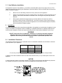
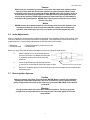
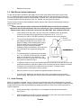
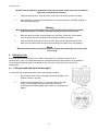
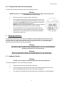
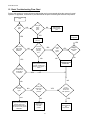
IMPORTANT FOR FUTURE REFERENCE
Please complete this information and retain this manual
for the life of the equipment:
Model #: __________________________
Installation and Operation Manual
Covering Model Series
SLG40 and SLG100
TM
Gas Safety
Certified
AS 4563
Cert. GSCS20190
SAI Global
L20-364 Rev 3
AUSTRALIA
Serial #: __________________________
Date Purchased: ___________________
THIS MANUAL MUST BE RETAINED FOR FUTURE REFERENCE
FOR YOUR SAFETY
DO NOT store or use gasoline or other flammable vapors or liquids in the
vicinity of this or any other appliance. Do not spray aerosols in the vicinity of
this appliance while it is in operation.
WARNING
Improper installation, alteration, service or maintenance can cause property
damage, injury or death. Read the installation, operating and maintenance
instructions thoroughly before installing or servicing this equipment.
TO THE PURCHASER
Post, in a prominent location, the
instructions to be followed in the event that
an operator smells gas. Obtain this
information from your local gas supplier.
casters must be stabilized by installing restraining
chains. If a flexible gas line is used, an additional
restraining cable must be connected at all times
when the appliance is in use.
WARNING
There is an open flame inside this appliance.
The unit may get hot enough to set nearby
materials on fire. Keep the area around the
appliance free from combustibles.
WARNING
An appliance equipped with casters and a flexible
gas line must be connected to the gas supply with
a quick disconnect device. This quick disconnect
must comply with AS4631. To limit the movement
of the appliance without depending on the
connector or quick disconnect, a restraining cable
must also be installed.
WARNING
DO NOT supply the appliance with a gas
that is not indicated on the data plate. If you
need to convert the appliance to another
type of fuel, contact your dealer.
WARNING
Installation of this appliance must be done by a
qualified professional. This appliance should be
inspected by a qualified professional on an annual
basis to insure safe and proper operation.
WARNING
DO NOT use an open flame to check for
gas leaks!
WARNING
This appliance must be installed in compliance
with AS 5601 (current revision) or local codes, as
applicable.
WARNING
If gas flow to appliance is interrupted, or pilots
extinguish, wait 5 minutes before attempting to
relight the pilot to allow any residual gas in
appliance to dissipate.
WARNING
If the appliance has a power supply, it must be
disconnected before servicing or cleaning this
appliance.
WARNING
Ensure that the appliance can get enough air to
keep the flame burning correctly. If the flame is
starved for air, it can give off a dangerous carbon
monoxide gas. Carbon monoxide is a clear
odorless gas that can cause suffocation.
WARNING
Do not attempt to move this appliance when the
unit is at operating temperature. Serious personal
injury could result if skin comes in contact with the
hot surfaces.
WARNING
Adequate means must be provided to limit the
movement of this appliance without depending on
the gas line connection. Single appliances
equipped with legs must be stabilized by installing
anchor straps. All appliances equipped with
WARNING
DO NOT sit or stand on this appliance. Serious
injury could result from falling or contact with hot
shortening/oil.
2
Table of Contents
1 Checking your New Appliance .................................................................................................................... 4 1.1 1.2 1.3 2 Assembly ................................................................................................................................................................ 4 Leg Installation and Leveling ................................................................................................................................. 4 Heat Deflector Installation ...................................................................................................................................... 5 Installation ................................................................................................................................................... 5 2.1 2.2 2.3 2.4 2.5 2.6 2.7 3 Installation Clearances ............................................................................................................................................ 5 Gas Connection ....................................................................................................................................................... 6 Quick Disconnect Gas Connection ......................................................................................................................... 6 Fuel Supply Line Leak and Pressure Testing .......................................................................................................... 6 Ventilation and Fire Safety Systems ....................................................................................................................... 6 Initial Adjustments .................................................................................................................................................. 7 Burner Ignition Systems ......................................................................................................................................... 7 Lighting Instructions .................................................................................................................................... 8 3.1 3.2 3.3 4 Pilot Flame Adjustment .......................................................................................................................................... 8 Main Burner System Adjustment............................................................................................................................ 9 Initial Cleaning ....................................................................................................................................................... 9 Filling the Tank .......................................................................................................................................... 10 4.1 4.2 5 Filling the tank with liquid shortening/oil ............................................................................................................. 10 Filling the tank with solid shortening/oil .............................................................................................................. 11 Operating Instructions ............................................................................................................................... 11 5.1 5.2 5.3 Appliance Start-Up ............................................................................................................................................... 11 Appliance Shutdown ............................................................................................................................................. 12 Power Failure ........................................................................................................................................................ 12 6 Daily Cleaning ........................................................................................................................................... 12 7 Thermostat Calibration .............................................................................................................................. 12 7.1 7.2 Thermostat Calibration Check (Standard) ............................................................................................................ 12 Thermostat Calibration ......................................................................................................................................... 13 8 Weekly Cleaning........................................................................................................................................ 14 9 Boil Out Procedure .................................................................................................................................... 14 10 Ventilation Hood Maintenance .................................................................................................................. 15 11 Gas Connection and Sealing Compound .................................................................................................. 15 12 Basic Troubleshooting Flow Chart ............................................................................................................ 16 13 SLG Series Operational Information ......................................................................................................... 17 14 SLG Series Parts List ................................................................................................................................ 17 15 Conversion Procedure:.............................................................................................................................. 18 3
SLG I&O Series
1
Checking your New Appliance
Your new appliance has been carefully packed into one crate. Every effort has been made to ensure that you it
is delivered to you in perfect condition. As you unpack your new appliance, inspect each of the pieces for
damage. If something is damaged, DO NOT sign the bill of lading. Contact the shipper immediately; the shipper
is only responsible for 15 days after delivery. Check the packing list enclosed with your appliance to ensure that
you have received all the parts to the appliance. If you are missing any parts, contact the dealer from whom the
appliance was purchased. As you unpack the appliance and its accessories be careful to keep the weight of the
appliance evenly distributed.
CAUTION
To prevent equipment damage and/or personal injury, do not tilt the appliance onto any
two of its legs, or pull the appliance by the flue vent.
1.1
Assembly
When you receive your appliance it is completely assembled with the possible exception of the legs and heat
deflector.
1.2
Leg Installation and Leveling
This appliance must be installed with legs; it cannot be curb mounted. Curb
mounting will seriously inhibit this appliances ability to effect proper combustion.
WARNING
This appliance must be installed with the legs provided by the manufacturer.
WARNING
Do not install legs or perform leveling procedure when unit is in operation or full of
cooking medium. Serious injury could result.
Required tools: 7/16 “ wrench and socket and a large pair of water pump pliers. The legs must be installed
before connecting the appliance to the gas supply. The legs provide the necessary height to meet sanitation
requirements and assure adequate air supply to the combustion system. Use the following procedure.
a.
Lay the appliance on its back, being careful not to damage the flue area by pulling on it. Protect
the outside of the appliance with cardboard or a drop cloth when laying it down.
b.
Attach each leg with the hex head screws and nuts supplied. Each leg requires four ¼-20 x 5/8”
hex head screws and nuts. Insure that all screws are tight.
c.
Mount the screws from the inside of the appliance with the nut on the outside (bottom) of the
appliance. The nuts have lock washers attached to them, therefore it is not necessary to use
lock washers
d.
When all four legs are securely mounted, stand the unit up, being careful not to put too much
weight on any one leg. Adjust the height and level the appliance by adjusting the leveling
devices (B) with water pump pliers.
4
SLG I&O Series
1.3
Heat Deflector Installation
If the appliance requires a heat deflector, you will find a removable label at the rear top edge of the unit. This
label has instructions for positioning and installation of the heat deflector. Refer to the label and the instructions
below to install the deflector.
2
a.
Remove the two self-drilling screws from the top, back area of the appliance.
b.
Position the heat deflector so that the angled portion of the deflector is facing toward the front of
appliance. Secure the heat deflector to the back of the unit using the two previously removed
fasteners.
c.
When properly installed the angled section of the heat deflector will extend over the flue
opening to redirect the heat. It SHOULD NOT cover the flue opening. Never allow anything to
block the flue opening; this will cause the appliance to over heat and inhibit proper combustion,
which could produce dangerous gases
Installation
If you have completed the above steps that are applicable to the appliance you purchased, the appliance is now
ready to be installed. The appliance must be installed by a qualified professional. A qualified professional will
ensure that the installation is safe and meets local building and fire codes and the installation code in force.
WARNING
DO NOT obstruct the flow of combustion, ventilation or air openings around the appliance.
Adequate clearance around the appliance is necessary for servicing and proper burner
operation. Ensure that you meet the minimum clearance requirements specified in this
manual.
2.1
Installation Clearances
The clearances shown below are for combustible and non-combustible installations and will allow for safe and
proper operation of your appliance.
Combustible
Construction
Back
Sides
Floor
6 in. (15 cm)
6 in. (15 cm)
N/A*
NonCombustible
Construction
6 in. (15 cm)
6 in. (15 cm)
4 ¾ (11.5 cm)
*For use only on Non Combustible Floors. This appliance must be installed on a fireproof base.
In addition to the above clearances there must also be at least 28 inches (71 cm) of aisle space in front of the
appliance.
NOTICE
In case the burners, injectors, gas supply manifold or any piping in the gas supply had shifted during shipment,
the installation technician is to check and correct any misalignment that may have occurred.
5
SLG I&O Series
2.2
Gas Connection
Your appliance will give you peak performance when the gas supply line is of sufficient size to provide the
correct gas flow. The gas inlet of the appliance is located in the back of the appliance on the lower RIGHT hand
side for the SLG100 and lower LEFT hand side for SLG40 about 21 cm from the floor The gas line must be
installed in accordance with the requirements of AS 5601 or local codes, by a qualified professional. Gas line
sizing requirements can be determined by a qualified installation professional, your local gas company or by the
Technical Regulator. The gas line needs to be large enough to supply the necessary amount of fuel to all
appliances without losing pressure to any appliance. A properly sized and installed gas line will deliver a
minimum supply pressure of 7.0 ± 2.0 inches w.c. (1.75 ± 0.5 kPa) for natural gas and 12.0 ± 2.0 inches (3.0 ±
0.5 kPa) for propane to all appliances connected to the supply line, operating simultaneously at full demand.
Each appliance is equipped to operate on one certain fuel type. The type of fuel with which the appliance is
intended to operate is stamped on the data plate, which is attached to the inside of the door.
Warning
NEVER supply the appliance with a gas other than the one that is indicated on the data
plate. Using the incorrect gas type will cause improper operation and could result in
serious injury or death. If you need to convert the appliance to another type of fuel,
contact the dealer you purchased it from.
Notice
NEVER use an adaptor to make a smaller gas supply line fit the appliance connection.
This may not allow proper gas flow for optimum burner operation, resulting in poor
performance and improper operation.
2.3
Quick Disconnect Gas Connection
Gas appliances equipped with casters must be installed in compliance with the applicable clauses of The
Standard for Gas Installations, AS 5601(latest edition). This connection should include a quick disconnect
device that complies with the Standard for Limited Flexibility Connectors, AS4631 (latest edition). When
installing a quick disconnect you must also install adequate means for limiting the movement of the appliance
without depending on the connector and quick-disconnect device or its associated piping to limit the movement
of the appliance. The restraining device should be attached to the appliance on the back panel.
2.4
Fuel Supply Line Leak and Pressure Testing
The fuel supply system must be tested before the appliance is used. If the fuel line is going to be tested at a
pressure greater than ½ PISG (3.45 kPa), insure that that appliance is disconnected from the fuel line. If the fuel
line is to be tested at a pressure equal to or less than ½ PSIG (3.45 kPa), the appliance can be connected
during the test, but the unit’s gas valve must be shut. Test all gas line connections for leaks with a solution of
soap and water when pressure is applied.
2.5
Ventilation and Fire Safety Systems
Your new appliance must have proper ventilation to function safely and properly. Exhaust gas temperatures can
reach as high as 1100 °F (593 °C). Therefore, it is very important to install a fire safety system. Your ventilation
system should be designed to allow for easy cleaning. Frequent cleaning and proper maintenance of the
ventilation system and the appliance will reduce the chances of fire.
It is essential that the appliance be operated only when adequate ventilation is provided. Your ventilation hood
should be properly maintained. A qualified installation professional should ensure that the hood is operating
properly in conjunction with the appliance. Inadequate ventilation may not properly evacuate appliance all
emissions. Excessive or unbalanced ventilation may cause drafts, which could interfere with proper operation of
the pilot and burners. Leave at least 18 inches (45.7 cm) of open space between the flue of the appliance and
the intake of the exhaust hood.
6
SLG I&O Series
Caution
Ensure that your ventilation system does not cause a down draft at the appliance’s flue
opening. A down draft will not allow the appliance to exhaust properly and will cause
overheating, which may cause permanent damage. NEVER point a fan or similar device at
or toward the flue opening of this appliance. Damage caused by down drafts will not be
covered by the warranty. NEVER allow anything to obstruct the flow of combustibles or
ventilation exiting the appliance. NEVER place anything on top of the flue area, or block
the flue in any way.
Notice
NEVER connect the ventilation blower or hood directly to the flue of this appliance. The
resulting increased flow of air through the combustion system will cause improper
operation, poor temperature recovery, poor ignition and could extinguish the pilot.
2.6
Initial Adjustments
After your appliance has been properly installed as described in the installation section of this manual, it will
need to be adjusted to ensure that it will perform as designed. These adjustments must be performed by a
qualified person. To perform these adjustments the following tools will be needed:
• Manometer
• DC Millivolt Meter
• Digital Thermometer (Temperature Probe)
• DC Milliameter
Before you begin filling and adjusting the appliance, perform the following visual checks:
a.
After the appliance is in its permanent location,
check the levelness. Any additional leveling that
is necessary can be performed as previously
described.
b.
Check the temperature probe and high limit bulb
(in the tank) to ensure that the mounting screws are tight.
c.
2.7
Ensure that these parts are tight.
Review the installation portion of this manual and ensure that all steps have been followed and
executed properly.
Burner Ignition Systems
Caution
Before proceeding any further, fill the tank with WATER. Water is used for the installation
adjustments because the temperature will never exceed 212°F (100°C), thereby allowing
plenty of adjustment time. Never let the water level go below the MIN LEVEL mark stamped
on the tank.
Warning
During operation there is an open flame inside this appliance. The unit may get hot
enough to set near by materials on fire. Keep the area around the appliance free from
combustibles.
7
SLG I&O Series
3
Lighting Instructions
For manual pilots, refer to the following instructions.
Warning
If pilot extinguishes, wait 5 minutes before attempting to relight the pilot to
allow any built up gas to dissipate.
3.1
a.
Open gas supply valves to the appliance.
b.
Turn the thermostat control knob counterclockwise to the OFF position.
c.
Turn the gas valve knob to the PILOT position. Push in on the knob while pressing the
ignitor button or hold a flame to the pilot until the pilot ignites; this may take a little while
the first time you light the pilot because of the air in the lines. Once lit, hold the knob in for
approximately one minute and then release.
d.
If the pilot goes out, wait 5 minutes and repeat step C. If after
three tries the pilot will not remain lit, refer to the operator
troubleshooting section of this manual.
e.
Once a pilot flame has been established, turn the gas valve
knob counterclockwise to the ON position.
f.
Set the thermostat control knob to the desired temperature
setting.
The main burners will ignite and be controlled by the
thermostat.
Pilot Flame Adjustment
REGULATOR ADJUSTOR
(UNDER CAP SCREW)
PILOT ADJUSTOR
(UNDER CAP SCREW)
For manual pilots, refer to the following instructions. Perform this procedure once the pilot is lit.
NOTE: This procedure requires a DC millivolt meter set to a scale of 0-1000 mV.
Using test leads with sharp probes will help in taking the required readings.
a.
Locate the thermopile wires coming from the thermostat/limit box going to the gas valve.
The wire size decreases near the gas valve connections.
b.
Using the positive (+) test probe, connect the probe to the high limit wire terminal. On
UFM systems, pierce the high limit wire insulation, with the tip of the test lead probe, at
the gas valve safety magnet connection.
c.
Connect the negative (-) test probe to the pilot tubing.
d.
Remove the cap screw located below the pilot tubing on the gas valve. The pilot flame
adjustment screw is recessed behind this. Turning the pilot flame adjustment screw
clockwise
lowers the pilot flame and millivolt output. Turning the pilot flame
adjustment screw counter- clockwise increases the pilot flame size
and millivolt output.
e.
While monitoring the DC millivolt meter, rotate the pilot flame adjustment
screw in the direction necessary to achieve a reading of 400 ± 50mV.
Note: Allow 3 to 5 minutes between flame adjustments to allow the reading to stabilize.
8
SLG I&O Series
f.
3.2
Replace the cap screw.
Main Burner System Adjustment
For the main burners to operate the gas supply valve must be open and the thermostat must be turned
on. For models with electric controls, the main power switch must be on. The main burners receive gas
from the main gas supply through the thermostatically controlled valve. When the thermostat is turned up
to a setting higher than the temperature of the oil in the tank, the gas control valve opens.
The main burner pressure must be adjusted to deliver optimum flame. Refer to the following procedure to
adjust the main burners.
CAUTION
Before proceeding any further, fill the tank with WATER. Water is used for the installation
adjustments because the temperature will never exceed 212°F (100°C), thereby allowing plenty of
adjustment time. Never let the water level go below the MIN LEVEL mark stamped on the tank.
a.
Ensure that the main gas valve is shut off; remove the manifold pressure tap plug and
connect an accurate pressure gauge having a range from 0 to 16 “ w.c. in 0.1”
increments (0 to 4 kPa in .025 kPa increments) or manometer with similar resolution.
b.
Turn on this and all appliances connected to the
gas supply line and light their main burners. The
pressure reading of the installed pressure gauge
should not drop from the required installation
pressure. Any loss of pressure indicates
inadequate supply line installation, which will cause
poor performance of all appliances during peak
usage.
c.
The installed pressure gauge should be the same,
±0.1” w.c. (.025 kPa), as that marked on the data
plate on the inside door of the appliance. If the
pressure is correct, go to step e, if it is not, adjust
the pressure as outlined in step d.
d.
To adjust the pressure, remove the regulator adjustment screw cap on the gas valve and, with
a flat head screwdriver, adjust the regulator screw until the proper burner pressure is reached.
Turning the screw clockwise will increase the burner pressure. Turning the screw
counterclockwise will decrease the burner pressure.
e.
When the pressure is correct, replace the regulator adjustment screw cover.
f.
Turn off the ALL appliances, shut the main gas valve to your appliance and remove the
pressure gauge. Apply pipe joint compound to the manifold pressure tap plug and reinstall it.
MAIN BURNER
3.3
MAIN BURNER ORIFICE
Initial Cleaning
When your appliance is shipped, many of its parts are covered with a thin coat of shortening/oil for protection.
Before the appliance is ready for cooking it must be cleaned. This will remove the shortening/oil coating and any
foreign matter that may have accumulated during storage and shipment. Refer to the following procedure to
clean the appliance.
a.
Fill the tank with water. Light the pilot, turn the appliance on and set the thermostat to
200°F (93°C).
b.
Allow the appliance to heat for 15 minutes. Add cleaner to the water, stirring with the cleaning
brush to ensure that the cleaner dissolves thoroughly.
Caution
9
SLG I&O Series
DO NOT leave the appliance unattended during cleaning. Never let the water level go below the
“Min Level” mark stamped on the tank.
c.
Using the cleaning brush, scrub the inside of the tank to remove the protective coating.
d.
When cleaning is complete turn the appliance off, drain the water into a container suitable for
hot water and dispose of it.
Warning
Wear protective gloves and clothing when cleaning and draining the appliance and when
disposing of water. The water is extremely hot and can cause severe injuries.
e.
When the tank has cooled, rinse thoroughly with cool water. Continue to rinse the tank
until the cleaner has been completely and thoroughly rinsed from the tank.
f.
Using a clean dry cloth, wipe out all of the water. Be very thorough when removing the
water, as any residual water will cause hot shortening/oil to splatter out of the appliance.
Notice
Mild steel tanks must be wiped down/coated thoroughly with shortening/oil to keep the tank
from rusting
4
Filling the Tank
Both liquid and solid shortening/oil can be used in this appliance, but liquid is preferred. If solid
shortening/oil is used it is recommended that you melt the shortening/oil before adding it to the appliance.
You can melt solid shortening/oil in the appliance, but you must be very careful not to scorch the
shortening/oil.
4.1
Filling the tank with liquid shortening/oil
To fill the tank with liquid shortening/oil refer to the following procedure.
a.
Ensure that the drain valve is completely closed and that there is no
residual moisture in the tank.
b.
Fill the tank with shortening/oil. You may fill the tank to the “MIN
LEVEL” mark or slightly below the nominal level mark: the
shortening/oil will expand slightly when it heats up, raising the level
slightly.
10
SLG I&O Series
4.2
Filling the tank with solid shortening/oil
To fill the tank with solid shortening/oil refer to the following procedure.
Warning
NEVER melt blocks of solid shortening/oil on top of the burner tubes. This will cause a fire
and could result in personal injury.
5
a.
Remove the screen covering the tubes (tube screen).
b.
Cut the solid shortening/oil into cubes no larger than one inch (2.54
cm). ALWAYS pack the shortening/oil below, between, and on top of
the burner tubes. DO NOT leave any large air gaps. Use care when
packing the solid shortening/oil into the tank.
DO NOT bend or break the temperature or high limit sensor probes. If
these are damaged the appliance will not function properly.
c.
Once the appliance tank is firmly packed with shortening/oil, the
shortening/oil must be melted. Melt the shortening/oil by cycling the
main burners on for 4 seconds and off for 30 seconds repeatedly,
using the thermostat knob.
Operating Instructions
To ensure the quality of the food you cook in this appliance, follow the preparation instructions from the
food manufacturer. Using the best shortening/oil makes the best fried foods. The best shortening/oil will
last longer than lower grade shortening/oil and save you money. When not in use, the shortening/oil
should be cooled and covered to prevent contamination.
Warning
This appliance must be installed using restraining devices to prevent accidental tipping or
movement. DO NOT attempt to move the appliance when it is in use or has hot liquid in it.
Splashing hot liquids can cause severe burns.
Warning
Water and shortening/oil DO NOT mix. Keep liquids away from hot shortening/oil.
Dropping liquid frozen foods into the hot shortening/oil will cause violent boiling.
5.1
Appliance Start-Up
Warning
DO NOT start the appliance without filling the tank with shortening/oil first!
To start up the appliance refer to the following instructions.
a.
Light the pilot as previously described in this manual
b.
Turn the temperature control knob (thermostat) to the desired temperature setting. This
knob is located behind the front doors or on the front control panel.
c.
The main burners will light and raise the shortening/oil temperature to the desired setting.
11
SLG I&O Series
5.2
Appliance Shutdown
There are two shutdown modes of appliance operation: STANDBY and COMPLETE. The standby mode
removes the ability of the appliances main burners to operate. Complete shutdown turns off the gas
supply to the appliance.
STANDBY
Turn the thermostat to the OFF position. Turn the Pilot knob clockwise to the PILOT
position. The cooker is now in Standby and can remain this way for only brief periods of
time. NEVER leave the appliance in standby mode for prolonged periods or overnight.
COMPLETE
Turn the thermostat to the OFF position. Depress and turn the Pilot knob counter clockwise to the OFF position. The appliance is now completely shut down and can be
cleaned and filtered if desired.
5.3
Power Failure
Caution
DO NOT attempt to operate this appliance during a power outage.
Wait five minutes after the power is restored before attempting to restart the appliance. This will allow time for
any gas that may have accumulated in the burner or tubes to dissipate. To restart the appliance, follow the
appliance start up procedure in this manual.
6
Daily Cleaning
Your appliance should be cleaned every day to maintain peak performance, proper sanitation and appearance.
Perform the following procedures daily.
a.
Wipe up any shortening/oil that spills onto the exterior of the appliance. This should be done with
a clean soft cloth while the shortening/oil is still warm.
b.
Use warm water with a mild detergent to clean surfaces. Be careful not to get water into the
shortening/oil and be sure to completely remove any detergent from the fry tank. Use a nonabrasive scouring powder or pad to clean stains if necessary.
Notice
Maintenance and repairs should be performed by qualified personnel. If you are
unsure, contact the factory, factory representative to locate the nearest qualified
Service Company.
7 Thermostat Calibration
7.1 Thermostat Calibration Check (Standard)
Notice
Thermostat calibration requires that the temperature of the appliance be raised above
boiling. If you have water in the tank you will need to drain it, dry it and fill it with
shortening/oil. Follow the filling instructions in this manual.
To check the calibration of your appliance, refer to the following procedure.
a.
Remove the tube screen from the tank.
b.
Place the tip of a digital thermometer probe in the shortening/oil approximately one inch
above the temperature sensor.
12
c.
d.
SLG I&O Series
Light the pilot as described in this manual, set the thermostat to 325°F (163 °C) and allow
the shortening/oil to come up to temperature. Watch the thermometer closely as the
temperature rises.
If the shortening/oil temperature reaches 350°F (167 °C) and the burners do not turn off,
turn the thermostat down. Keep lowering the thermostat setting until the burners go out.
Caution
If the burners do not shut off at the LOWEST thermostat setting, the thermostat may be
defective. Contact your local service company.
e.
7.2
Let the appliance cycle 4 to 6 times before checking the temperature. Compare the
thermometer temperature against the thermostat setting. If the values are more than 5°F
(3 °C) apart, calibrate the thermostat using procedure in this manual.
Thermostat Calibration
For Gas Operated and Electric Thermostats refer to the following procedure.
a.
Remove the tube screen from the tank and place the tip of a digital thermometer in the
shortening/oil approximately one inch above the temperature sensor.
b.
Light the pilot as described in this manual, set the thermostat to 325°F (163 °C) and allow
the shortening/oil to come up to temperature; let the appliance cycle 4-6 times to insure that the
shortening/oil temperature has stabilized. Compare the thermostat setting of 325°F (163 °C) to
the digital thermometer reading.
Remove the thermostat dial by pulling the knob straight out. DO NOT rotate the dial.
c.
d.
Holding the outside of the shaft so that it DOES NOT MOVE, scrape away the sealing
compound in the center of the shaft with a small flat blade screwdriver.
e.
Turn the adjustment screw clockwise to lower the thermostat’s temperature setting or counterclockwise to raise it.
Note
One-quarter turn of the adjustment screw changes the temperature setting
approximately 24°F (13 °C).
f.
Turn the adjustment screw until the burners come on at 325°F (163 °F).
g.
Replace the knob and allow the appliance to cycle 4 to 6 times. Check the temperature of the
digital thermometer against the thermostat dial setting; if there is greater than a 5°F
(3 °C) difference, repeat the calibration procedure.
13
SLG I&O Series
h.
8
Weekly Cleaning
The appliance should be thoroughly cleaned AT LEAST once a week. This should include a thorough wipe down
of the entire appliance with a rag and mild detergent.
Warning
The power supply must be disconnected before cleaning and servicing this appliance!
Warning
NEVER spray cleaner into the main burners or pilot. This could act as a magnet for dust and
other debris, causing it to accumulate and inhibit the proper operation of your appliance.
9
Boil Out Procedure
The appliance should be boiled out AT LEAST once a week to remove food debris and shortening/oil build up.
You will need a container large enough to hold 1 ½ times the shortening/oil in the tank. Refer to the following
procedure for weekly boil out.
Warning
Completely shut the appliance down when the shortening/oil is being drained and
replaced with water. This will prevent the main burners from coming on during the
draining and filling procedure.
Warning
At operating temperatures, the shortening/oil in the appliance is VERY HOT and can cause
severe burns. Do not let the hot shortening/oil touch your skin or clothing. ALWAYS wear
insulated, oil proof gloves, protective clothing and eyewear when working on a hot
appliance.
a.
Drain the shortening/oil from the appliance and discard or save for reuse. Remove the tube
screen. Close the drain valve and fill the tank with warm water and non-caustic detergent
b.
Restart the appliance as described in this manual and set the thermostat to 200°F (93 °C). Bring
the water to a slow boil. DO NOT allow the water to boil excessively as this will cause excessive
foaming and boil over.
c.
Allow the appliance to soak for 20 minutes to soften shortening/oil deposits. Use the cleaning
brush to scrub and remove any residue from the tank, tubes and side walls.
d.
When finished drain the water and wipe the tank dry with a soft clean cloth.
e.
Ensure that the drain valve is closed and replace the tube screen.
f.
You may now refill the tank with shortening/oil per the filling instructions in this manual.
14
SLG I&O Series
10 Ventilation Hood Maintenance
Proper ventilation hood operation is very important for the correct operation of this appliance and the safety of
personnel. The ventilation hood should be inspected at the time of installation of this appliance to insure that it
will operate properly in conjunction with the appliance. A regular schedule of examination and maintenance, to
ensure operation in accordance with AS 4566 latest edition and/or applicable local codes, must be followed.
OIL TEMPERATURE
Keep the oil temperature in the fryer to a maximum of 190°C. Higher temperatures will cause rapid
breakdown of the oil and give you no faster cooking. At 205°C to 210°C the life of the oil is only one third of its
life at 190°C. In addition, increased decomposition causes the oil to smoke badly even if the temperature is
lowered to 190°C again. High oil temperatures give you no advantage, cost you money and increase the fire
danger.
TEMPERATURA DELL’OLIO
Mantenere la temperatura dell’olio nella friggitrice fino a un massimo di 190°C. Temperature maggiori causano un
rapido degrado dell’olio, senza tuttavia eseguire una cottura più rapida. Da 205°C a 210°C la durata dell’olio è
inferiore di un terzo rispetto a quella a 190°C. Inoltre, l’accresciuta decomposizione comporta una forte emissione di
fumo, anche se la temperatura viene riportata di nuovo a 190°C. Le alte temperature non prevedono vantaggi, sono
antieconomiche e aumentano il rischio d’incendio.
ΘΕΡΜΟΚΡΑΣΙΑ ΛΑΔΙΟΥ
Διατηρείτε τη θερμοκρασία λαδιού στη φριτέζα μέχρι 190 βαθμούς Κελσίου. Υψηλότερες θερμοκρασίες θα αλλάξουν
τη σύνθεση του λαδιού πολύ σύντομα και δεν ψήνετε γρηγορότερα. Η δυναμικότητα του λαδιού στους 205-210
βαθμούς Κελσίου είναι μόνο το ένα τρίτο (33%) της δυναμικότητάς του στους 190 βαθμούς Κελσίου. Επιπλέον η
αυξημένη αποσύνθεση του λαδιού, σε θερμοκρασίες πάνω από 190 βαθμούς Κελσίου, κάνει το λάδι να καπνίζει
άσχημα κι αν ακόμη κατεβάσετε τη θερμοκρασία κατόπιν πάλι στους 190 βαθμούς Κελσίου. Οι υψηλές θερμοκρασίες
δε σας παρέχουν κανένα πλεονέκτημα, σας κοστίζει περισσότερα χρήματα και αυξάνουν τον κίνδυνο πυρκαγιάς.
11 Gas Connection and Sealing Compound
As with any gas appliance, be sure to use a suitable gas joint sealant whenever gas connections are loosened
and retightened. Also remember to check for leaks before allowing the appliance to be put into service.
15
SLG I&O Series
12 Basic Troubleshooting Flow Chart
Refer to this section to correct common problems that may be encountered during the course of normal
operation. If applicable, a schematic is provided behind the panel containing the electrical components.
Appliance does not
work.
Will the
pilot
light?
Is the gas
supply
valve
open?
NO
NO
Open the gas
valve and light
pilot
YES
YES
Reset switch
and light pilot.
Purge air from
gas line
YES
Does pilot
stay lit after
pilot knob is
released?
Is all the
air purged
from the
pilot gas
line?
NO
Is high
limit
switch
open?
YES
Contact a
qualified service
technician
Purge air from pilot line by
turning pilot knob to the
"PILOT" position and
holding it in for approx. 1
minute.
Does pilot go
out when the
temperature
increases?
YES
NO
NO
Do the main
burners
light?
YES
If the main burners are
lighting, but not performing
properly refer to the
INSTALLATION section of
this manual to verify proper
installation.
NO
NO
NO
YES
Will high
limit switch
reset?
YES
NO
Is the gas
valve knob in
the "ON"
position?
YES
NO
Is the
thermostat
knob in the
OFF position?
YES
Turn the gas
valve knob to
the "ON"
position.
Turn the
thermostat knob
to a
temperature
16
SLG I&O Series
13 SLG Series Operational Information
Model
SLG40
Total Gas Consumption
90 MJ/h
Burner Pressure Natural Gas
0.87 kPa
Burner Pressure Propane Gas
2.50 kPa
Injector Size: Main Burners
2 of
Natural Gas 3.05 mm (#31)
Propane Gas
1.90 mm
Injector Size: Pilot
1 of
Natural Gas 0.56 mm (N22)
Propane Gas 0.41 mm (LP16)
Minimum Tank Capacity
18.1 kg
Cooking Area Length
37 mm
Cooking Area Width
36 mm
Overall Height
121 cm
Overall Width
40 cm
Overall Depth
70 cm
Shipping Weight
66 kg
SLG100
158 MJ/h
0.87 kPa
2.50 kPa
4 of
2.82 mm (#34)
1.78 mm (#50)
2 of
1.32 mm (#55)
0.635 mm (#72)
31.8 kg
46 cm
46 cm
120 cm
50 cm
79 cm
91 kg
14 SLG Series Parts List
Part Number
Natural Gas
LP
Gas Valve
PP11001
PP11002
Thermocouple
P5047540
Thermostat
P5047590
Thermostat Knob
PP10539
High Limit Switch
PP10084
Bulb Clamp
A1408002
Pilot
A8047001 A8047002
Pilot Orifice
P6071666 P6071665
Ignitor
P9131-55
Ignitor Control
P9132-34
Main Burner
E4556-04
Main Burner Orifice P8905-04 A8047103
Burner Support Bar
B13790-00
Wing Nut
4003-0295900
Tube Rack
P9800-45
Basket
P9800-08
Basket Hanger
P9054-01
Drain Valve
60084502
Drain Extension
P9313-60
Component
Model
SLG100
SLG40
Model
17
Part Number
Natural Gas
LP
Gas Valve
PP10955
PP10956
Thermocouple
P5047540
Thermostat
P5047590
Thermostat Knob
PP10539
High Limit Switch
PP10084
Bulb Clamp
A1408002
Pilot Burner Tube
P8903-19 P8903-18
Pilot Orifice
P9131-62 P8904-99
Ignitor
P9131-55
Ignitor Control
P9132-34
Main Burner
E4556-04
Main Burner Orifice P8905-83 A8047102
Burner Support Bar
B14052-00
Wing Nut
4003-0295900
Tube Rack
P9800-42
Basket
P9800-48
Basket Hanger
C9183-00
Drain Valve
60084502
Drain Extension
P9313-60
Component
SLG I&O Series
15 Conversion Procedure:
Ensure the appliance is not in use, is in a cooled state and that the tank has been emptied. Do not perform this procedure on
a hot appliance or an appliance filled with hot liquid.
To convert appliance:
1.
2.
3.
4.
5.
6.
7.
8.
9.
10.
11.
12.
Close the main gas supply at the supply point.
Ensure that the control valve is closed by turning it to the “OFF” position.
Remove the regulator on front face of gas control and replace it with the one from the conversion kit.
Undo and remove the wingnuts from the top of the burners. Remove the wingnuts and burner retainer plate.
Remove burner. This will make removing the pilot (on SLG40) or runner tube (on SLG100) easier.
Loosen the brass fitting on the gas valve holding the pilot line.
Remove the mounting screws on pilot bracket (SLG40) or ignitor bracket (SLG100)
For the SLG40 – Completely remove gas line to pilot and replace pilot orifice.
For the SLG100 – Completely remove the gas line to runner tube, disassemble and replace runner tube orifices.
For the SLG40 – Re-assemble pilot and re-install the pilot to appliance.
For the SLG100 – Re-assemble runner tube and re-install it into appliance. Remount the ignitor bracket.
Replace main burner injectors.
Replace the burners.
Install the burner plate and wingnuts. Tighten wingnuts.
18
SLG I&O Series
19
SLG I&O Series
In the event of problems with or questions about your
order, please contact the Anetsberger Factory at:
In the event of problems with or questions about your
equipment, please contact the Anetsberger Authorized
Service and Parts representative (ASAP) covering
your area, or contact Anetsberger at the number listed
to the left.
+001 (603) 225-6684 (World Wide)
MAILING ADDRESS – P.O. BOX 501, CONCORD, NH 03302-0501
SHIPPING ADDRESS – 10 FERRY ST., CONCORD, NH 03301
20


![国民生活センターについて[PDF形式]](http://vs1.manualzilla.com/store/data/006694186_2-4afa641d6170535ab4009f566ac7fbee-150x150.png)