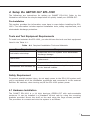
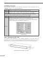
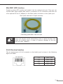
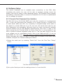
1
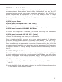
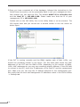
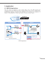
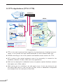
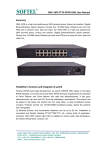
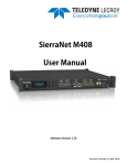
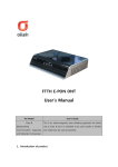
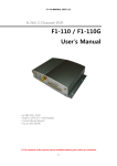
GEPON OLT
EPL-1000
Quick Installation Guide
Table of Contents
1. Introduction................................................................................................ 3
2. Package Contents........................................................................................ 4
3. Overview ................................................................................................. 5
4. Setup the GEPON OLT EPL-1000................................................................... 7
4.1 Hardware Installation............................................................................ 7
4.2 Software Setup...................................................................................13
4.2.1 Console Port Command Line Interface..........................................13
4.2.2 GUI Utility Installation................................................................15
5. Application................................................................................................17
5.1 GEPON Applications.............................................................................17
5.2 FTTx Applications (FTTH / FTTB)...........................................................18
Further information..........................................................................................19
1. Introduction
EPON is a point to multipoint communications protocol based on Gigabit Ethernet.
It allows a Gigabit Ethernet communications fiber to be shared by multiple end
users using a passive optical splitter. EPON communication takes place between
an Optical Line Terminal (OLT) and multiple Optical Network Units (ONUs). Using
standard terminology, downstream traffic flows from OLT to ONU, and upstream
traffic flows from ONU to OLT. A protocol called Multi Point Control Protocol (MPCP)
is used to arbitrate the channel between the ONU’s so that no collisions will occur
on the common fiber.
With growing network services such as HDTV, IPTV, voice-over-IP (VoIP) and
Multimedia broadband applications, and the demand of broadband rises quickly. The
present Broadband environment has not already accorded with needing; however,
Passive Optical Network (PON) would be the most promising NGN (Next Generation
Networking) technology to fulfill the demand.
PLANET EPL-1000 is a GEPON Optical Line Terminal (OLT) which designed with
one GEPON port, one Gigabit TP / SFP Combo Interface and one management
port. It is easy installation and maintenance for GEPON deployment. Applications
with PLANET GEPON Optical Network Units (ONU) EPN series, PLANET EPL-1000
can provide highly effective GEPON solutions and convenient management for
Broadband network. PLANET GEPON technology provides the high bandwidth up to
1.25Gbps for both upstream and downstream, up to 20km Long-Distance Coverage
between equipment nodes, Scalability and Flexibility for network deployment. It is
a cost-effective access technology with reliable and scalable network for Triple-play
service applications.
With high split ratio at 1:32 and support the usage of PLANET ONUs, EPL-1000
can minimize the investment cost for carriers. By using the advanced technology
in the telecommunication industry, the EPL-1000 will provide strong functionalities
for Ethernet features such as QoS, VLAN, Multicast, DBA (Dynamic Bandwidth
Allocation), and Access Control List. The EPL-1000 is an ideal solution for FTTx
applications.
2 Package Contents
EPL-1000
l EPL-1000 Unit x 1
l AC Power Cord x 1
l Quick Installation Guide x 1
l CD (Containing User’s Manual, QIG, Utility) x 1
l Console Cable x 1
l Rack-mounting x 2
l Screw Package x 1
If any of above items are damaged or missing, please contact your dealer
immediately.
3. Overview
Front Panel
The front panel of EPL-1000 is shown below.
EPL-1000
Front Panel LED and Port definition
LED
PWR
LNK/ACT
MGMT
100M
DUPLEX
COL
TX
RX
Uplink
Status
On
The indicator will light when OLT is opened
Off
Checking the power or power supply adaptor, make sure
power supply has connected well
On
Light when equipment normally connect with 100Mbps ONU
port
Glitter
Glitter when the port receive or transfer data
On
Corresponding indicator is on when 100Mbps equipment
connect with relevant port
Off
Be off when 100Mbps port does not joint equipment
On
Be on when port is working base on full duplex mode
Off
Be off when port is working base on half duplex mode
Glitter
Collision happens base on half duplex mode
Off
Normal work status
On
Be on when the 1000Mbps port is transferring data
Off
Be off when the 1000Mbps port has no data to transfer
On
Be on when the 1000Mbps port is receiving data
Off
Be off when the 1000Mbps port has no data to receive
On
Be on when 1000Mbps equipment connects with relevant
port
Off
Be off when 1000Mbps port does not joint relevant
equipment
On
Be on when 100Mbps equipment connects with relevant port
Off
Be off when the port does not joint 100Mbps equipment
1000
10/100
Description
ALM1
ALM2
ALM3
Status
ALM4
OPT
SYS
RESET
Glitter
There will be one ONU or OLT alarm
Off
Normal work status
Glitter
There will be one ONU or OLT alarm
Off
Normal work status
Glitter
There will be one ONU or OLT alarm
Off
Normal work status
Glitter
There will be one ONU or OLT alarm
Off
Normal work status
Glitter
The link to the switch fiber port is failing
Off
The link to the switch fiber port is normal
Glitter
The link to the local 1000Mbps port is failing
Off
The link to the local 1000Mbps port is normal
ON when the system reset button is pushed
Front Panel Port Definition
Port
Port Description
PON Port
The PON connector allows data communication between
the ONU and the OLT through a single mode fiber.
Mini-GBIC Port
Gigabit Ethernet SFP trunk port.
10/100/1000M Port
Gigabit Ethernet electrical trunk port.
MGMT Port
RJ-45 (10/100Base-TX) Port for GUI Utility Management.
Console Port
(9600, 8, N, 1)
RS-232 port for system configuration and maintenance.
RESET
Reboot EPL-1000
Rear Panel
Rear Panel Port Definition
Port
Port Description
AC PWR
AC Power cord plug-in, 100 - 240V AC is allowed.
Power Switch
Power On / Off switch
4. Setup the GEPON OLT EPL-1000
The followings are instructions for setting up PLANET EPL-1000. Refer to the
illustration and follow the simple steps below to quickly install your GEPON OLT.
Pre-Installation
This section provides the information users have to ware before installing the EPL1000. The information includes required installation tools, safety requirements, and
electrostatic discharge protection.
Tools and Test Equipment Requirements
To install and maintain the EPL-1000, you should have the tools and test equipment
listed in the Table 4‑1.
Table 4‑1 Required Installation Tools and Materials
Item Required
Purpose
Anti-static wrist strap
Protect the EPL-1000 system from electrostatic
discharge damage.
Hand tools
Screw drivers for equipment removal and
replacement.
Wire cutter/stripper
Prepare wires for electrical connections.
Accessories and hardware kit
Screws, bolts, etc., for securing the equipment
on the desired location.
Safety Requirement
To prevent possible serious injury, do not apply power to the EPL-1000 system until
you’ve completed all of the installation procedures and connected it to the external
facilities. Be cautious, when turning on/off the EPL-1000 system power.
4.1 Hardware Installation
The PLANET EPL-1000 is a 1U high box-type GEPON OLT with rack-mountable
enclosure. It can be installed in a standard 19-inch rack by using the mounting
brackets provided. Mount the shelf on the rack using the large screws provided.
The procedure to connect and wire the system is as follows.
Installation Overview
The installation consists of the following procedures. Each procedure will be
explained in detail in the following sections:
Step 1:
Mount the system into the desired location of a rack.
Step 2:
Connect to the AC power supply, and then check the voltage. Make
sure the power is proper for EPL-1000 and plug in the Power.
After executing the previous procedures, please check the cable connection
robustness and correctness before turning on the power supply.
Step 3:
Connect the network cable and optical to EPL-1000.
Connect Console cable to COM port of a computer for CLI
management. Then run the terminal program with the setting shown
below: Please see more details on Chapter 4.2.
Step 4:
Console Setting
Step 1. Mounting the EPL-1000
The position and orientation of the brackets depends on the rack used for
mounting. The OLT can be front-mounted in a standard channel rack; and it can be
shipped with the mounting brackets installed in one of three mounting positions.
Mounting Bracket Orientation (Top View)
After the site requirements have been verified, the chassis may be installed at the
specified location. When mounting the chassis, practice good safety habits. Use
two or more people to secure the chassis. Relay rack mounting normally requires
at least two people.
Step
Action
1
Locate the chassis and obtain the appropriate chassis mounting
hardware.
2
Determine and obtain the tools required for the chassis mounting
hardware.
3
From the front of the relay rack, position the chassis in its relay rack
mounting location.
4
Using the appropriate rack mounting hardware, secure the chassis in its
relay location on both left and right side of mounting bracket.
Mounting Bracket Position for Standard Mount
Note
Warning
The chassis should be empty during the chassis mounting procedures. Remove any unit in the chassis, and store them according to
static-sensitive device storage procedures.
Hazardous voltages may exist on the chassis. Always practice good
safety habits when wiring a live circuit or performing maintenance.
Step 2. Power Connections
AC Power Connection
Connect the AC power cord to the AC supply socket on the rear panel of the OLT,
and plug the cord into the external power source. The voltage must be 100 to
240V AC (±10% tolerance).
Warning
Ensure that all power sources to the chassis (power distribution
panel) are turned off during the connection.
Step 3. Connecting the Uplink Interface
Uplink Connection
The system supports one Gigabit TP / SFP Combo (SFP GbE and 10/100/1000BaseT) Interface. You can select the proper media for your applications.
10
Mini-GBIC (SFP) Interface
Prepare a proper SFP module and install it into the optical trunk port. Then you can
connect fiber optics cabling that uses LC connectors or SC connectors (with the use
of an optional SC-to-LC adapter) to the fiber optics connector on the uplink port.
Fiber optics cable with LC duplex connector
Connecting optical fiber to the trunk port
Warning
Never look directly at the transmitting ports of optical interface that
might be emitting laser, in order to prevent damage to the eye
from the laser radiation.
RJ-45 Electrical Interface
The pin assignment of RJ-45 connector on the Uplink port is shown in the following
figure and table.
1,2
T/Rx+,T/Rx-
3,6
T/Rx+,T/Rx-
4,5
T/Rx+,T/Rx-
7,8
T/Rx+,T/Rx-
11
Step 4. Connecting the PON Interface
PON Connection
The system supports one fixed PON port, the max. Split ratio is up to 1:32 per
PON port. Connect the single mode fiber to the Splitter or ONUs. The PON port
provides the high bandwidth up to 1.25Gbps for both upstream and downstream,
up to 20km Long-Distance Coverage between equipment nodes.
Step 5. Connecting the Console Port and MGMT Port
You can use the Console Port and MGMT Port to manage the EPL-1000. The
connection figure is shown below; please follow next section to setup your system.
12
4.2 Software Setup
This section illustrates how to establish basic connectivity on the PON. After
completing this section the user will be able to transport packets across the
system, and will be ready to start advanced testing. The Software Setup consists
of installing a Terminal utility to access the Evaluation Kit CLIs and a sophisticated
GUI to manage the system.
4.2.1 Console Port Command Line Interface
The EPL-1000 has a 10/100 Mb MGMT port in for the connection of a management
GUI. It also has Command Line Interface (CLI) access through a Console port
on each board (ONU and OLT). By connecting a straight-through serial cable to
any board to a serial COM port on a PC, the user can access each chip for low
level diagnostics and debugging. Although there are many commercial available
Terminal Utilities such as MS Windows HyperTerminal, Tera Term is used in this
User’s manual as the Terminal Utility of choice. Tera Term is recommended if you
wish to perform firmware upgrades using the CLI. This has been found to be the
most reliable tool for downloading binary files to the ONU and OLT. It can be
downloaded for free from http://hp.vector.co.jp/authors/VA002416/teraterm.html.
Please download and install on each PC being used to connect to EPL-1000. Once
installed, configure the Transmit settings as follows.
1)Setup the serial port by selecting “Serial Port” from the Tera Term “Setup”
menu.
Tera Term Serial Port Settings
2)Set up the Serial port with the settings shown in 0 and click OK.
13
EPL-1000 GUI Personality Setup
The EPL-1000 supports a 10/100Mb Management interface for User-Friendly
GUI Management. Prior to installing the GUI, it may be necessary to modify the
Host and Management IP addresses configuration stored in the OLT personality
flash. It can either be left as the defaults or changed to suit your own network
environment.
You can see what the current settings are by typing the following commands.
Commands shown below must be entered at the Tera Term command prompt for
the EPL-1000.
1) 3721/>pers [Enter]
2) 3721/pers/>show [Enter]
This will result in information about the state of the personality flash being
displayed. The items near the end of the prints are the current Management
Interface Settings. Typically the factory settings are:
Management interface settings:
Physical interface: ethernet
Management VLAN: 4095
Transport protocol: udp
Local IP config: static
Host IP config: static
Host IP: 192.168.1.100
Mgmt IP: 192.168.1.101
Netmask: 255.255.255.0
The Mgmt IP address refers to the IP address of the OLT 10/100Mb MGMT Port.
The Host IP address refers to the IP address of the PC which is running the GUI
Utility. The default settings are for both of these IP addresses to be statically
assigned. The netmask should be set to suit the class of the IP addresses. In
addition to the 10/100Mb MGMT Port, management can also be performed in-band.
In this case the MGMT Port is not connected. Instead the OLT is programmed for
in-band management and the user sets the VID of the VLAN used for management.
The Transport protocol should always be set to UDP.
The following sections outline how to change the settings for each of the
management options.
14
MGMT Port – Static IP Addresses
If you are controlling the EPON system from a local PC connected directly to the
management port, these settings should suffice. Additionally if you have the OLT
connected to your network and you are using local addressing in the 192.168.1.x
subnet, they will also be appropriate. If on the other hand you wish to change
them to match you local network, you may do so as follows:
To change the IP Address assigned to the Host PC (this must match the Host PC IP
Address):
1) 3721/>pers [Enter]
2) 3721/pers/>hostip 192 168 1 100 [Enter]
To change the IP Address that is assigned to the OLT management port:
1) 3721/pers/>mgmtip 192 168 1 101 [Enter]
If you are not using Class C Addresses, you should also change the netmask to
suit:
1) 3721/pers/>netmask 255 255 255 0 [Enter]
To make the new settings take effect you must reboot.
Prior to installing the GUI, you must set up your network adapter’s IP address to
match the setting found in the OLT’s personality flash (default = 192.168.1.100).
Set the adapter’s IP to match the value found in the personality flash for Host IP.
Once the adaptor is set appropriately, connect an Ethernet cable to the 10/100 Mb
management port. In addition you should also set the Management Port Parameters
in the GUI’s Utilities -> Settings dialog. These should match the settings found in
the CLI.
4.2.2 GUI Utility Installation
The Utility comes with sophisticated software Graphical User Interface (GUI). It
is highly intuitive and allows the user to control the EPON and set such things
as SLAs, bridging and VLAN modes, static table entries, and to perform firmware
upgrades etc. It is found in the Utility folder on the CD provided. To install and use
the GUI, do the following:
1)Copy the contents of your CD to the PC you will be using as your EPON management PC.
2)Locate the Utility folder and create a shortcut to the GUI Utility.exe file and place
on your desktop or somewhere suitable.
15
3)Once you have connected all of the hardware, followed the instructions in the
Initial Power Up section, set the personality flash to suit your management interface method you can start the GUI. The default MGMT IP is 192.168.1.101
and the Host IP is 192.168.1.100. Please make sure that the IP of your
management PC is 192.168.1.100.
Double click on the GUI Utility Icon in the Utility folder or at the shortcut. The
GUI should start and you should see a window similar to the one shown as
below figure.
If the OLT is running normally and the ONUs register each of their LLIDs, you
should see something similar to the figure. The left hand pane shows the MAC
addresses of the OLT and the ONU’s LLIDs. Depending on the number of ONUs,
LLIDs, MAC addresses etc you may see something slightly different. If the GUI fails
to connect to the OLT, check the IP addresses of the Host PC and the management
port. Make sure you can ping the IP address assigned to the management port.
Also verify that the Host and management IP addresses match in the GUI’s Utilities
-> Settings tab.
16
5. Application
5.1 GEPON Applications
The OLT device is deployed in the central office room. The ONU devices are
connected to the OLT device through an optical splitter, which forms a P2MP (Pointto-Multipoint) topology, connect to the switches or the devices as computers, IP
Phone, IP Surveillance for Triple Play Service. Shown as below Figure.
GEPON OLT
IPTV
Internet
VoIP
Campus
High Rise Buildings
EPN-104
PON
EPN-102
IPTV
PON
IP Phone
EPN-102
Camera
PON
IP Surveillance Application
PC
1000Base-T UTP
100Base-TX UTP
Triple-Play Application
PON
Passive Optical Network
GEPON Applications
17
5.2 FTTx Applications (FTTH / FTTB)
GEPON OLT
IPTV
Internet
VoIP
FTTB
FTTH
High Rise Buildings
Community
EPN-102
PON
IPTV
PC
PON
PON
IPTV
EPN-104
PON
IP Phone
IP Phone
Splitter
PON
EPN-102
Camera
Splitter
PON
IPTV
EPN-104
PC
PC
IP Phone
1000Base-T UTP
100Base-TX UTP
PON
PON
EPN-102
IPTV
Passive Optical Network
FTTx Applications
l FTTx is the main trend and final target for the development of optical communication. It can provide the high speed bandwidth to users without traffic jam.
l GEPON technology is the most practical and feasible access solution for FTTx.
l OLT is setup in the central equipment room of a community, to connect to the
backbone networks of data, video and voice applications.
l ONU can be deployed at residential homes via passive optical distribute network
that spans up to 20km radius.
l ONU can be put in a building or an end user’s room. A user can choose to use
the whole ONU alone or just one port of ONU, which is bandwidth configurable
and isolated from the rest ports of the ONU.
18
Further information
The above steps introduce simple installations and configurations for EPL-1000.
For further configurations and information can be found in the user’s manual CD.
Please check the user’s manual for more understandings. If you have any other
questions, please contact the local dealer where you purchasing this product.
19
This page is intentionally left blank