1
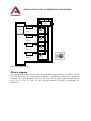
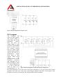
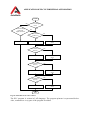
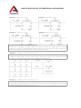
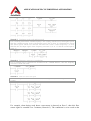
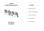
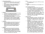
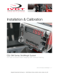
APPLICATION OF PLC IN INDUSTRIAL AUTOMATION
Chapter XI
Control of an application with a frequency converter
There are several ways how to control drives with a PLC. The start and stop features are
easily controlled with the DOs of a PLC, but the speed control varies from application to
application. The simplest way is to use the built-in DIs of the frequency converters. For
example with two DIs available, four different preset frequencies can be called, as shown in
the example in Table 0.1. It is required to study the table in the drive user manual because
variations exist between different drive manufacturers. Combinations of three DIs on a drive
already allow 8 discrete frequencies to be set.
Table 0.1. Preset frequency selection according to the state of inputs
Digital Input 1 state
0
0
1
1
Digital Input 2 state
0
1
0
1
Preset frequency
Preset frequency 1
Preset frequency 2
Preset frequency 3
Preset frequency 4
The preset frequency values are pre-programmed using the drive menu. The DIs of the drive
are electrically connected to DOs in the S7-300 PLC SM. All that has to be done in STEP 7 is
to write a program that controls these output values in accordance with application-specific
input conditions determined by the system designer.
The drawback of using the digital signals is that only a limited number of previously
determined frequencies can be used. To overcome this, most variable speed drives have also
built-in AIs, usually 0-10 V or 4-20 mA. This allows the PLC to control the speed of the drive
directly with an analog signal. Usually the lowest analogue signal 0 V or 4 mA equals 0 Hz of
the frequency converter and the highest analog signal 10 V or 20 mA to 50 Hz. This analog
signal controlling the drive speed can, for example, be the output of a PID control FB.
Another way to control a frequency converter is to use field bus communication like
PROFIBUS, ROFINET, MODBUS, etc. Besides speed control it allows one to change other
frequency converter parameter values like acceleration, deceleration, choose different speed
control modes and monitor electrical drive parameter values like voltage, current, torque, etc.
Communication possibilities of a frequency converter field bus are covered in detail in the
user manual.
Application example
In this application example a control system of the ventilation in a warehouse with 4 floors is
given (Fig. 0.1) [2]. Every floor has an infrared motion sensor to detect if workers are present
and it sends a signal to the PLC, which controls the speed and air valves of the ventilation
pump. There is a press button (S1) on floor 1 that allows the ventilation system to work over
time.
APPLICATION OF PLC IN INDUSTRIAL AUTOMATION
Timer
PLC
FC
Ventilation
pump
L4_SEN
M
Lift
Floor 4
L4_VAL
L3_SEN
M
Floor 3
L3_VAL
L2_SEN
M
Floor 2
L2_VAL
L1_SEN
M
Floor 1
L1_VAL
Fig. 0.1. Warehouse layout
Electric diagram
The electric part of the system consists of four infrared motion sensors (L1_SEN, L2_SEN,
L3_SEN, L4_SEN), one separate timer (TIMER), one pushbutton switch (S1), a frequency
converter (FC), four contactors (K1, K2, K3, K4), four air valves with electrical motors
(L1_VAL, L2_VAL, L3_VAL, L4_VAL) and one Siemens S7-300 PLC (with digital I/O
module(s)).
APPLICATION OF PLC IN INDUSTRIAL AUTOMATION
Fig. 0.2. Electric diagram for the power part
PLC program
The ventilator can
work on three speeds.
The lowest speed is
used when any of the
movement
sensors
does not have an
output signal or only
one does. The medium
speed is used in case
two motion sensors
have an output signal
and the fastest speed is
used in the case of a
simultaneous
signal
from three or four
sensors. These speed
values
are
preprogrammed on the
frequency
converter
and controlled via its
DIs according to Table
0.1. Preset frequencies
1, 2 and 4 from the
table are used. It is Fig. 0.3. Electric diagram for control circuit (low voltage part)
recommended to set
the preset frequency 3 to be the same as the preset frequency 2. It is not used in the control
program, but in this case if the wires connecting the outputs of the PLC to the inputs of the
frequency converter are mixed up, the program still works as intended.
APPLICATION OF PLC IN INDUSTRIAL AUTOMATION
To prevent turning off the ventilation during short periods of no movement in the storage
area, timers (T0, T1, T2, T3) in the control program are used to increase the life span of the
signals from motion sensors. If a movement is detected during the signal delay period, the
corresponding timer value is reset.
An external timer is used to turn the ventilation off after the work day and to turn it back on
again in the morning. There is a switch to override the timer signal manually and turn the
ventilation on during other times - for example if working extra hours is needed.
A signal from the movement sensor causes opening of the air valve on the given floor to allow
the air to enter this floor. The timer (T0, T1, T2, T3) signals are also used here.
Flowchart diagram can be used to describe this sample application. In Table 0.2 the symbols
column shows the flowchart symbols mainly used [23].
Table 0.2. Main symbols of the flowchart
Name of
symbol
Terminator
Symbol
Description (meaning)
Used to present the start and end of the
flowchart diagram. Flowchart diagram is
drawn between these symbols. Word
“START” marks the flowchart start and word
“END” the end.
Used to present action, task or process, which
is written inside the rectangle.
START
END
Process
Filling a
bottle
Decision
Is the bottle
filled?
Yes
Delay
No
Presents the condition, by which the program
moves on to the next task or process. Each
decision can have at least two (or more)
answers which are written next to outgoing
arrow lines. In most cases the answers are
“Yes” and “No” or “True” and “False”.
Presents the waiting period or delay time that
is normally part of a process.
Wait for
2s
Data
Show filled
bottle number
on the display
Presents data input and/or output from the
flowchart.
APPLICATION OF PLC IN INDUSTRIAL AUTOMATION
Name of
symbol
Stored data
Symbol
Description (meaning)
Presents data storage in the flowchart.
Store the
working hours
of the machine
Predefined
process
Presents a process step or series of process
steps that are declared and defined elsewhere
(in different parts of the same document).
Bottle filling
Connector
A
A
Off-page
connector
1
1
Page 1
Page 2
Presents a jump from one point to another in
the flowchart. The connectors show jumps
which occur on same page. Connectors are
usually labeled with capital letters (A, B, AA)
to show matching jump points.
Presents a jump from one page to another in
the flowchart (this means that the flowchart
continues on the next page). Off-page
connectors are usually labeled with numbers
(1, 2, 11).
Figs 0.4 and 0.5 present the control algorithms (flowcharts) of the warehouse ventilation
system. The first algorithm controls the ventilator and the other one controls the air valves.
Sample project programs composed according to the algorithms are executed separately and
almost at the same time.
APPLICATION OF PLC IN INDUSTRIAL AUTOMATION
START
No
Is it working
time?
Is the working
time timer
signal canceled?
Yes
Yes
Switch the
ventilation pump on
No
Have movements been
detected on one floor or
on none of the floors?
No
Have movements
been detected on
three or more floors?
Yes
No
Yes
Switch the
ventilation pump off
Ventilation pump
works with the
lowest speed
Ventilation pump
works with the
highest speed
Ventilation pump
works with the
medium speed
END
Fig. 0.4. Flowchart of ventilation pump control
The variables used in the PLC programs are shown in Table 0.3. Speed1 and Speed3 are
auxiliary variables to simplify the program writing.
Table 0.3. Variables of the project
Symbol
L1_SEN
L2_SEN
L3_SEN
L4_SEN
TIMER
Address
I 124.0
I 124.1
I 124.2
I 124.3
I 124.4
Data type
BOOL
BOOL
BOOL
BOOL
BOOL
S1
FC_IN1
FC_IN2
FC_WORK
L1_VAL
L2_VAL
L3_VAL
L4_VAL
Speed1
Speed3
I 124.5
Q 124.0
Q 124.1
Q 124.2
Q 124.3
Q 124.4
Q 124.5
Q 124.6
M 0.0
M 0.1
BOOL
BOOL
BOOL
BOOL
BOOL
BOOL
BOOL
BOOL
BOOL
BOOL
Comment
Movement sensor on floor 1
Movement sensor on floor 2
Movement sensor on floor 3
Movement sensor on floor 4
Signal is “1” during 8 am – 5 pm Mon – Fri. All other
times it is “0”
Manual control, which overrides the “TIMER” signal
Signal to DI 1 of the frequency converter
Signal to DI 2 of the frequency converter
Work signal (“1”) to the frequency converter
Open the air control valve on floor 1
Open the air control valve on floor 2
Open the air control valve on floor 3
Open the air control valve on floor 4
Drive working on lowest speed
Drive working on highest speed
APPLICATION OF PLC IN INDUSTRIAL AUTOMATION
START
No
Is the working
time timer
signal canceled?
No
Is it working
time?
Yes
Yes
Movement
on floor 1?
No
Yes
Close all air valves
Close the floor 1 air
valve
Open the floor 1 air valve
Movement on
floor 2?
No
Yes
Close the floor 2 air
valve
Open the floor 2 air valve
Movement on
floor 3?
No
Yes
Close the floor 3 air
valve
Open the floor 3 air valve
Movement on
floor 4?
No
Yes
Open the floor 4 air valve
Close the floor 4 air
valve
END
Fig. 0.5. Flowchart of air valve control
The PLC program is written in LAD language. The program printout is represented below.
Also, comments to every part of the program are added.
APPLICATION OF PLC IN INDUSTRIAL AUTOMATION
Network 1: Movement sensor 1
Network 2: Movement sensor 2
Network 3: Movement sensor 3
Network 4: Movement sensor 4
Networks 1 to 4 are used to program the life span of the signals from movement sensors. If a
movement is detected, the timer output is activated. When the signal from the sensor
disappears, the timer is started and the output is kept active during the time written in input TV.
When a new signal is detected from the sensor, the timer is reset.
Network 5: Ventilation works with lower speed
If only one movement sensor is active or none are active and it is working time, then the
ventilation pump works with the lowest speed. Since this is the lowest speed, the Preset
frequency 1 is used and both inputs of the frequency converter are “0”.
Network 6: Ventilation works with higher speed
If at least three movement sensors have signal “1” and it is working time, then the ventilation
pump works with the highest speed. In this case Preset frequency 4 is used, therefore both input
signals of the frequency converter are set to “1”.
APPLICATION OF PLC IN INDUSTRIAL AUTOMATION
Network 7: Ventilation works with medium speed
If it is working time and the ventilation pump is not working with the lowest and highest speed,
then the ventilation pump works with medium speed. This is done, by eliminating the lowest
and fastest speeds which were detected with networks 5 and 6. Preset frequency 2 is used,
therefore the first input signal of the frequency converter is set to “0” and the second input is
set to “1”.
Network 8: Frequency converter is switched on
If it is working time or someone has switched on the “TIMER RESET”, then the frequency
converter is in the run mode.
Network 9: Floor air valves are open
If it is working time and a floor movement sensor has signal “1”, then the respective air valve
is open.
For example, when during work hours a movement is detected on floor 3, then this floor
sensor signal is extended over 5 minutes (Network 3). The ventilation is set to work on the
APPLICATION OF PLC IN INDUSTRIAL AUTOMATION
lowest speed (Network 5) and the valve on floor 3 is opened (Network 9). After 5 minutes, if
no more movements were detected there, floor 3 valve is closed.
Also, warehouse lighting system can be fully automated so that the workers do not have to
switch on and off the lights. To update the application only four contactors are needed, which
switch each floor lights on and off, and a simple program change is needed in network 9.