1
CANspy
v1.3 13-Mar-2009
CANspy
32/16-channel CAN Port
Switch
user manual & reference
v1.3, 13 March 2009
Henk Boterenbrood, Henk Groenstege, Jaap Kuijt
NIKHEF, Amsterdam, The Netherlands
1
CANspy
v1.3 13-Mar-2009
Table of Contents
1
DESCRIPTION .................................................................................................................. 3
2
CONNECTORS AND INTERFACES ............................................................................. 6
3
CANSPY CONTROL SOFTWARE................................................................................... 8
4
CANSPY CANOPEN FIRMWARE................................................................................ 11
4.1 INITIALISATION ........................................................................................................................ 11
4.2 NODE GUARDING AND LIFE GUARDING .................................................................................. 12
4.3 CONFIGURATION STORAGE ..................................................................................................... 13
4.3.1
Storing Parameters and Settings...................................................................................... 13
4.3.2
EEPROM Memory Map ................................................................................................... 14
4.4 UPGRADING THE FIRMWARE ................................................................................................... 15
4.5 CANSPY OBJECT DICTIONARY................................................................................................ 16
4.6 EMERGENCY OBJECTS ............................................................................................................. 20
REFERENCES........................................................................................................................ 22
Version History
Version Date
Comments
1.3
13 Mar 2009
Some updates to text and chapter naming;
addition of a figure with a depiction of a CANspy on a bus and a
figure with pictures of the ATLAS MDT system.
1.2
2 Dec 2008
New pictures.
1.1
25 Nov 2008
Corrections in text and pictures.
1.0
10 Nov 2008
Describes firmware version "CS10.0000".
Table 1.
Document change record.
2
CANspy
v1.3 13-Mar-2009
1 Description
CANspy is a 1HE high 19-inch module, allowing a user to connect a CAN interface port to
an existing CAN bus, selectable from up to 32 CAN buses. These CAN buses are connected
in pairs to the sixteen D9 connectors on the frontpanel of the CANspy module. If CAN cables
with standard connector layout are used, up to 16 CAN buses can be connected to the CANspy
module.
The selected CAN bus connection is routed to the ‘spy’ connector on the backpanel of the
CANspy module, which in turn is typically connected to a CAN interface port on a PC, thus
allowing a user to connect his PC to anyone of the up to 32 CAN buses connected to the CANspy, for ‘spying’ on or active control of this bus. The selection of a bus is controlled through a
separate CAN bus connection on the CANspy running at a bit rate of 125 kbit/s. On this CAN
connection the higher-level CANopen protocol [1] [2] is used as the communication protocol
standard. The CAN messages used for the CANspy operation are described later in this document in the section on the CANspy firmware.
So by using only two CAN ports on his PC a user is able to connect to an almost unlimited
number of CAN buses, since CANspy modules can be daisy-chained, on its controlling CAN
bus as well as its ‘spy’ port. In the latter case a user should take care to connect only one CAN
bus of all CANspy modules on the chain, in order not to make a connection between two independent CAN buses!
A software tool is provided for controlling multiple CANspy modules in such a setup. A
brief description of the tool can be found in section 3.
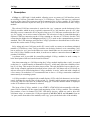
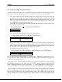
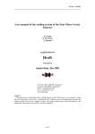
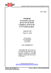
Note that connecting to a CAN-bus using the CANspy module implies that a ‘stub’ is created
on the bus (i.e. a cable branch) as illustrated in Figure 1, which may affect the reliability of the
bus if it is long. This needs to be taken into account. The stub should be kept as short as possible. In the example application described below (where all CAN-buses run at 125 kbit/s) no
adverse effects were found using three CANspy modules ‘in series’ and a stub with a length of
a few meters. Nevertheless it is recommended not to leave a CANspy connection connected
unnecessarily in a running system.
A CANspy module is equipped with a small display (LCD, with 2x8 characters) on its frontpanel, showing the current state of the switch, i.e. standby (which means not connected) or
connected. The user can store an 8-character string per CAN-bus channel which is displayed
on the LCD whenever the channel is selected.
The heart of the CANspy module is an ATMEL AT90CAN64 microcontroller with integrated CAN controller for the control and monitoring of the CANspy module. The switching
part consists of two 16-channel TLC5923 LED driver devices, which are used to drive the
solid-state relays to connect the CAN-port signals (CAN-H, CAN-L and Ground) from an
‘in’-port (on the front side of the module) to the ‘spy’-port (on the back side of the module).
3
CANspy
v1.3 13-Mar-2009
CAN
node
CAN
node
CAN bus
Host
PC
CANspy
CAN bus
for
CANspy
control
‘stub’
‘spy’
PC
Figure 1.Schematic drawing of a CANspy module connected to a CAN bus.
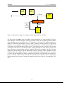
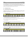
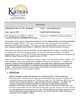
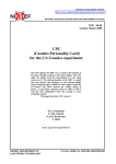
See the pictures in Figure 2 for an example of the application of CANspy modules. The pictures illustrate a real-life example of CANspy modules used in the ATLAS experiment’s MDT
muon chamber system, consisting of ca. 1150 chambers. This system is equipped with more
than 80 CAN-buses connecting to devices used to monitor various sensors on each muon
chamber and to configure and monitor the frontend electronics of each muon chamber. All
CAN buses end up on interfaces in PCs (up to 12 CAN-buses per PC). Power for the devices
connected to the buses is fed through wires running through the same cables as the CAN
buses. The power is provided by the power supplies. These power supplies relay the CAN bus
signals and conveniently provide an additional CAN-bus connector on their frontpanel for the
CAN bus cable they supply with power, and this is where the CANspy modules are connected
to. Three CANspy modules are used to connect all CAN buses. This allows a user (system expert) to remotely connect to any of the buses from only one of the PCs, either to monitor the
running system or to look at or debug for example a problem on a device on a particular CAN
bus
4
CANspy
v1.3 13-Mar-2009
Rack with powersupplies
for the CAN-bus
equipment
Rack with PCs
with CAN interface
cards
CANspy
modules
CANspy
module
Figure 2.Picture at top: the rack on the left contains the power supplies for the CAN-bus
equipment. Three CANspy modules connect to each bus through the CAN-connector
available on the frontpanel of a power supply. The rack on the left holds the PCs that
contain the CAN interfaces that connect to each of the around 80 CAN-buses. Each
PC connects to up to 12 CAN-buses.
Picture at bottom: detail of the CAN-bus power supply rack with CANspy module.
Each CANspy module connector connects to 2 CAN-buses using a 1-to-2 fanout cable with D9 connectors.
5
CANspy
v1.3 13-Mar-2009
2 Connectors and Interfaces
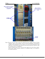
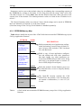
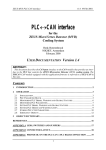
Figure 3 shows pictures of the CANspy module front and back panels, highlighting its connectors. The layout of the connectors is detailed in Table 2 and Table 3.
16 (double) CAN ports (male), in
LCD display,
with status information
CAN port, spy, D9 female
(2 connectors for easy daisy-chaining)
CAN port, for CANspy control, D9 female
(2 connectors for easy daisy-chaining)
Power input connector (7-12V), with screw holes alongside
for installation of a cable restraint
Figure 3.Views of the CANspy module frontside and backside.
6
CANspy
v1.3 13-Mar-2009
function
pin
pin
function
1
CAN-L, bus ‘B’
CAN-H, bus ‘B’
6
2
CAN-L, bus ‘A’
CAN-H, bus ‘A’
7
3
CAN-GND, bus ‘A’
not connected
8
4
CAN-GND, bus ‘B’
not connected
9
5
CAN-SHIELD
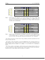
Table 2. Layout of the CAN connectors (‘in’) on the frontside of the CANspy module. Bus
‘A’ is connected according to the CAN(open) standard, so if standard cables are
used up to 16 CAN-buses can be connected to the CANspy module and only the
‘A’ buses can be switched then.
function
pin
pin
function
1
not connected
not connected
6
2
CAN-L
CAN-H
7
3
CAN-GND
not connected
8
4
not connected
not connected
9
5
CAN-SHIELD
Table 3. Layout of the CAN connectors (‘CONTROL’ and ‘SPY’) on the backside of the
CANspy module; there are 2 connectors for easy daisy-chaining multiple modules
on one CAN-bus. All 9 pins of the connectors of each pair are 1-to-1 connected.
Note that the CAN bus for control of the CANspy module(s) should be terminated at the last
CANspy module on the bus.
The module's CAN node identifier is stored in EEPROM and can be changed remotely (see
Object Dictionary index 3300h and 3301h in section 4.5) and is shown periodically on the
CANspy display (when the module is in ‘standby’, i.e. no CAN bus ‘in’ is connected to
‘SPY’).
The CANspy module's serial number, which it has been given during production testing, can
be read out remotely (see Object Dictionary index 3100h in section 4.5) and is also shown periodically on the CANspy display (when the module is in ‘standby’).
7
CANspy
v1.3 13-Mar-2009
3 CANspy Control Software
The CANspy Control program provides a user interface for controlling multiple CANspy
modules (all connected to the same controlling CAN bus), whereby only a single CAN port
connection is ‘active’ at any time. See Figure 4. If a new connection is selected on a another
CANspy module a ‘disconnect’ command is sent to all other CANspy modules first. In this
way it is possible to daisy-chain the ‘spy’ ports of the CANspy modules, without accidentally
connecting two independent CAN buses to each other.
The program also provides an interface for setting and modifying the labels (names) for the
inputs. See Figure 5. The labels are stored in the CANspy module. Labels are 8-character
strings that allow the user to assign more user-friendly names for the CAN inputs rather than
to have to remember which input number represents which CAN bus.
The software runs under MS Windows and supports all Kvaser CAN-bus interfaces (a version for National Instruments CAN-bus interfaces can be made available on request).
8
CANspy
v1.3 13-Mar-2009
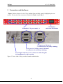
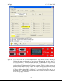
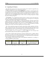
Figure 4.
User interface for the CAN-bus input selection (top) and the CANspy display reflecting the status as shown in the user interface (bottom). In this case input 7A
with label “Sector 4” is selected and connected. In subwindow CANspy Control
the CAN-bus interface port through which the CANspy modules are controlled,
can be selected. This automatically triggers a scan for CANspy modules present on
the bus. In subwindow CANspy Module one of the CANspy modules found on the
bus can be selected from the drop down menu. In this case a CANspy module with
CANopen address 4 and label “CANspy04” is selected. By selecting any one of
the inputs 1A to 16B and then clicking the Connect button this input is connected
to the CANspy ‘spy’ connector.
9
CANspy
v1.3 13-Mar-2009
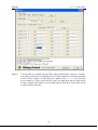
Figure 5.
User interface for module and port label editing and storage. Labels are 8 characters long at maximum. By clicking the Store button labels are stored permanently
in the CANspy module. A label shown as dashes only (“--------“) has not been
given a name yet. There is one label for each CAN input port and one label for the
CANspy module itself which is conveniently shown in the drop down menu for the
CANspy module selection.
10
CANspy
v1.3 13-Mar-2009
4 CANspy CANopen Firmware
4.1
Initialisation
When the CANspy firmware initialises, the hardware devices are reset and configured (LCD
and a switch chip) and error counters and registers are reset.
After power-up, watchdog reset, manual reset or a CANopen initiated reset action (i.e. by an
NMT Reset-Node message, see below) a CANopen node sends a so-called Boot-up message
(as defined by the CANopen standard) as soon as it has finished initializing (hardware, software); this is a CAN-message with the following syntax:
CANspy module (NMT-Slave)
COB-ID
700h + NodeID
→
Host (NMT-Master)
Data Byte 0
0
NodeID is the CAN node identifier stored in the CANspy’s EEPROM. NodeID is in the
range between 1 and 127.
To generate a soft reset the following CANopen NMT message must be sent:
Host (NMT-Master) → CANspy module (NMT-Slave)
COB-ID
000h
Data Byte 0
81h
(Reset_Node)
There is no reply to this message.
Data Byte 1
NodeID or 0
(0: all nodes on the bus)
Note that at power-up it is the Bootloader application firmware that becomes active first and
is in control of the CANspy module; the Bootloader reports its presence by sending the following Emergency message (see also section 4.4):
Bootloader
COB-ID
080h +
NodeID
→
Host
Byte 0-1
Emergency
Error Code
(00h 50h)
Byte 2
Error Register
(Object 1001h)
(80h)
Byte 3-7
Manufacturer specific error field
(FEh 00h 64h ZZh 00h)
(ZZh = MCUSR)
(MCUSR = MCU Status Register; for details see section 4.6 or the AT90CAN64 microcontroller datasheet).
Having the Bootloader activate at power-up guarantees that it is always possible to upload
new application software to the module, even when the application currently programmed is
faulty or corrupted.
After about 4 seconds the Bootloader automatically jumps to the application. Alternatively,
the Bootloader starts the application immediately, if it receives an NMT Reset-Node message
–as shown above- within this period.
11
CANspy
4.2
v1.3 13-Mar-2009
Node Guarding and Life Guarding
Node Guarding in CANopen is a mechanism whereby an NMT-master checks the state of
other nodes on the bus, at regular intervals. It can do this in one of two different ways:
1. The master sends a Remote Transmission Request (RTR) for the Node Guard message,
to each node on the bus, in turn; a node that receives the RTR, sends the Node Guard
message, which contains one data byte indicating the (CANopen) state of the node, as
well as a toggle bit. If a node does not reply the master should signal this to the higherlevel software and/or take appropriate action.
The RTR for the Node Guard message looks like this (a Remote Frame, so the CANmessage has no data bytes):
Host (NMT-Master)
→
CANspy module (NMT-Slave)
COB-ID
700h + NodeID
The reply Node Guard message from a node looks like this:
CANspy module (NMT-Slave)
COB-ID
700h + NodeID
→
Host (NMT-Master)
DataByte 0
bit 7: toggle bit,
bit 6-0: state
2. Each node on the bus sends a Heartbeat message at regular intervals; typically, the
NMT-master monitors these messages and keeps a time-out period for each node. The
master detects nodes that stop sending their Heartbeat messages and should signal this
to the higher-level software and/or take appropriate action.
A Heartbeat message looks like this:
CANspy module (Heartbeat producer)
COB-ID
700h + NodeID
→
Consumer(s) (e.g. NMT-Master)
DataByte 0
State
State is one of these CANopen states: 0 (Initializing), 4 (Stopped), 5 (Operational) or 127
(Pre-operational). Note that this makes the Boot-up message the first Heartbeat message after
a node reset (see previous section).
According to the CANopen standard, a node is not allowed to support both Node Guarding
and Heartbeat protocols at the same time. The CANspy module supports both methods of
Node Guarding (but indeed not at the same time), i.e. it can send the Node Guard message or
it can send the Heartbeat message with an interval, which is configurable in OD index 1017h.
Life Guarding in CANopen is a mechanism whereby a node checks the aliveness of the host
or master, by applying a time-out on messages received. CANopen defines that the message to
time-out is the RTR for the Node Guard message, sent by the NMT-master; however, the
CANspy module resets its Life Guarding timer at each properly received message addressed to
it.
12
CANspy
v1.3 13-Mar-2009
Life Guarding is controlled through OD objects 100Ch and 100Dh. In the CANspy module
the Life Guarding time-out can be set between 1 and 255 seconds, by setting OD index 100Dh
to the corresponding value, or can be switched off, by setting OD index 100Dh to zero.
If a Life Guarding time-out occurs, the node should take whatever appropriate action. The
CANspy module resets and reinitializes the CAN-controller, and (tries to) resume(s) normal
operation, after sending an Emergency message (see section 4.6).
4.3
Configuration Storage
4.3.1 Storing Parameters and Settings
Parameters and settings can be stored permanently onboard in non-volatile memory
(EEPROM) by writing string "save" to OD index 1010h. The SDO mechanism is used to accomplish this, using the following message:
Host
→
CANspy module
Data Byte
COB-ID
0
1
2
600h +
0x23
0x10
0x10
NodeID
3
subindex
4
73h
('s')
5
61h
('a')
6
76h
('v')
7
65h
('e')
with OD index 1010h in byte 1+2 and subindex in byte 3 with subindex:
= 1: store all parameters (as listed for subindex 2 and 3).
= 2: store communication parameters (concerning CAN, PDOs and Node- and Life Guarding).
= 3: store application parameters (not applicable for CANspy).
= 4: see next section.
If the store-operation succeeded the CANspy module sends the following reply:
CANspy module → Host
Data Byte
COB-ID
0
1
580h +
0x60
0x10
NodeID
2
0x10
3
subindex
4
–
5
–
6-7
–
If the store-operation did not succeed the CANspy module sends the following reply (SDO
Abort Domain Transfer, error reason: ‘hardware fault’ (for more details see [1])):
CANspy module → Host
Data Byte
COB-ID
0
1
2
580h +
80h
10h
10h
NodeID
3
Subindex
13
4
0
5
0
6
6
(Error Code)
7
6
(Error Class)
CANspy
v1.3 13-Mar-2009
Parameters can be reset to their default values (by invalidating the corresponding contents of
the EEPROM) by writing to OD index 1011h, using this time the string "load" (6Ch, 6Fh,
61h, 64h) in bytes 4 to 7 of the SDO. Note that the default values take effect only after a subsequent reset of the module. The default parameter values are listed in the OD tables in section 4.5.
The Object Dictionary tables in section 4.5 show which settings can be stored in EEPROM:
these are marked by an asterisk (*) in the first column
(Note that storage of the CANspy Serial Number is handled separately).
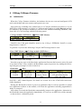
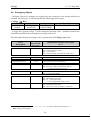
4.3.2 EEPROM Memory Map
Table 4 below details the layout of the AT90CAN64 microcontroller EEPROM usage by the
CANspy application firmware.
EEPROM
not used
ADDR
0000h
0001h
CANspy
configuration
parameters
00A0h
00A1h
Rad-tolerant
working copy
of global
settings and
parameters
not used
CANspy
Serial
Number
Node-ID (opt)
00FEh
00FFh
0100h
DESCRIPTION
Holds permanently saved application configuration and settings, stored in up to 8 blocks of
up to 16 bytes each; includes a CRC checksum
for each data block.
Holds a copy of most application configuration and settings and some other parameters
that don't change very often; parameters are
reread from EEPROM each time before being
used; this is an optional feature to counter effects of SEE (Single Event Upset).
Holds the module’s Serial Number given to it
at production time; serves to uniquely identify
the module.
0106h
0107h
0108h
not used
The 'Node-ID' location contains the CAN
Node-ID for the module; if the location does
not contain a valid number (1<=val<=127) 63
is used.
0FFFh
Table 4.
AT90CAN64 microcontroller EEPROM memory map of the CANspy application
firmware.
14
CANspy
4.4
v1.3 13-Mar-2009
Upgrading the Firmware
The application program in the CANspy microcontroller can be replaced or upgraded by uploading new program code via its control CAN connection.
A Windows application program called ELMBloader is available for performing this firmware upgrade (it was developed for the ELMB module which contains an ATmega128 microcontroller, but has since been upgraded to operate on AT90CAN microcontrollers too, provided they have been programmer with the proper bootloader firmware; see below). The upgrade process leaves the EEPROM intact, in other words: all existing configuration settings
are preserved during an upgrade.
The Bootloader [3] is an application program stored in a separate section of the microcontroller flash memory. It handles the firmware upgrade process, receiving series of CAN(open)
messages containing the programming instructions and code.
After power-up of the CANspy module, it is always the Bootloader, that takes control of the
module. After about 4 seconds the Bootloader automatically jumps to the start of the CANspy
application program, or immediately, when it receives a CANopen NMT Reset-Node message.
However, the Bootloader remains in control if it receives a valid programming command
within those 4 seconds. The firmware upgrade process may then begin.
The CANspy application program can transfer control of the module explicitly to the Bootloader, when one writes any value to the 8-bit object 5E00h in the Object Dictionary of the
CANspy application. In this case the Bootloader does not automatically jump to the CANspy
application program after 4 seconds. The firmware upgrade process may now begin.
After the upgrade process, the reception of a CANopen NMT Reset-Node message causes
the Bootloader to jump to the start of the new application program.
If the CANspy module sends an Emergency message as shown below, it signifies that the
Bootloader is in control of the module. Note that the same Emergency message is also sent as
the first message after power-up, when the Bootloader is in control for the first 4 seconds after
power-up, before jumping to the application program.
The Bootloader can be forced to jump to the application immediately, by sending it a
CANopen NMT Reset-Node message.
COB-ID
080h +
NodeID
Byte 0-1
Emergency
Error Code
(00h 50h)
Byte 2
Error Register
(Object 1001h)
(80h)
Byte 3-7
Manufacturer specific error field
(5 bytes: FEh,80h,64h,ZZh,00h,
with ZZh = MCUSR)
(MCUSR = MCU Status Register contents; for details see section 4.6).
15
CANspy
4.5
v1.3 13-Mar-2009
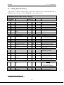
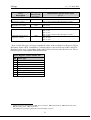
CANspy Object Dictionary
The values of objects marked with ∗ in the Index column can be stored permanently in
EEPROM. They are retrieved from EEPROM at reset and power-up.
Communication Profile Area (CANspy)
Index
(hex)
Sub
Index
Description
Data/
Object
Attr
1000
-
Device type
U32
RO
00000000h
1001
1002
-
Error register
Manufacturer status reg
U8
U32
RO
RO
0
0
1008
1009
100A
0
VisStr
VisStr
VisStr
RO
RO
RO
"CSPY"
"CS10"
"CS10"
1
Manufacturer device name
Manufacturer hw version
Manufacturer software
version
minor version number
VisStr
RO
"0000"
-
Guard time [ms]
Life time factor
U16
U8
RO
RW
1000
0
Store parameters
Highest index supported
Save all parameters
Save communication parameters
Save application par's
Array
U8
U32
U32
RO
RW
RW
3
1
1
U32
RW
1
Restore default parameters
Array
0
1
Highest index supported
Restore all parameters
U8
U32
RO
RW
3
1
2
Restore communication
parameters
Restore application par's
U32
RW
1
U32
RW
1
Producer Heartbeat Time
[1 s]
U16
RW
0
Identity
Number of entries
Vendor ID
Record
1..4
U32
RO
RO
1
12345678h
100C
100D
*
1010
0
1
2
3
1011
3
1017
*
-
1018
0
1
1
Default
Comment
Meaning: no specific device profile
1
(see footnote)
= CANspy module
= CANspy v1
CANspy application v1.0.0
= 1 second
Life Guarding timeout in seconds;
0 → no life guarding timeout
Save stuff in onboard EEPROM
Read: 1; Write "save": store all
Read: 1; Write "save": store
PDO par's, Life time factor, …
Read: 1; Write "save": store
ADCs config, …
Invalidate stuff in onboard
EEPROM; use defaults
Read: 1; Write "load": invalidate
all parameters stored
Read: 1; Write "load": invalidate stored PDO par's, etc.
Read: 1; Write "load": invalidate stored ADCs config, etc.
In units of seconds (but <=255 !),
(NB: actually should be in ms according to CANopen!);
0 → Heartbeat is disabled
Mandatory CANopen object
Manufacturer Status Register: byte0 = ….
16
to be ordered from CiA
CANspy
v1.3 13-Mar-2009
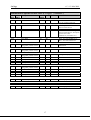
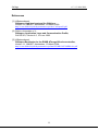
Manufacturer-specific Profile Area (CANspy)
Index
(hex)
Sub
Index
2000
(continued…)
Description
Data/
Object
Attr
-
CAN Port Switch
U8
RW
0: disconnect
1 to 32: connect CAN port
2010
-
Open Detection Mask
U32
RO
“LED Open Detection” bits of
the TLC5923 devices
2020
-
Dot Correction
U8
RW
LED Dot Correction setting for
the TLC5923 devices; all outputs
get the same value
(default: 63, maximum 127)
2030
-
Error Flags
U8
RO
Bit 0: TLC5923 XERR active
Bit 1: TLC5923 TEF active
2040
-
CANspy LCD description
string (char position 1 to 4)
U32
RW
e.g. for “ABCD” write value
44434241h
2041
-
CANspy LCD description
string (char position 5 to 8)
U32
RW
U32
RW
0
1
…
32
CAN port LCD description
string (char position 1 to 4)
Number of entries
CAN port 1
…
CAN port 32
U8
U32
…
U32
RO
RW
…
RW
U32
0
1
…
32
CAN port LCD description
string (char position 5 to 8)
Number of entries
CAN port 1
…
CAN port 32
U8
U32
…
U32
RO
RW
…
RW
2050
2051
Default
Comment
String for display on the LCD
32
String for display on the LCD
32
2100
-
LCD data byte
U8
RW
(for test purposes)
2110
-
LCD (DDRAM) addr byte
U8
RW
(for test purposes)
2120
-
LCD busy bit
U8
RO
(for test purposes)
17
CANspy
v1.3 13-Mar-2009
Manufacturer-specific Profile Area (CANspy)
Index
(hex)
Sub
Index
3000
0
1
Attr
(continued…)
Description
Data/
Object
Default
Program Code CRC
Number of entries
Check 16-bit CRC of program code in FLASH
memory
Record
U8
U16
RO
RO
3
0
0
2
3
Get CRC
U16
U16
RO
RO
3100
-
Serial Number
U32
RW
3101
-
Enable Serial Number
write operation
U8
WO
CAN-controller settings
and status
Number of entries
Format error interrupt
counters
Record
U8
U32
RO
RO
4
2
3
Enable auto-start
Bus-off max retry counter
U8
U8
RW
RW
0
2
4
Received message counter
U8
RO
-
CAN Node Identifier
U8
WO
3200
0
1
*
*
3300
Comment
SDO reply unequal to zero
means there is a checksum error;
absence of CRC results in SDO
Abort with Error Code 1;
error while accessing FLASH
results in SDO Abort with Error
Code 6.
not used
Return CRC from flash
Number or 4-byte string
uniquely identifying a CANspy
module, given during production.
Writing 5Ah enables one write
operation on the Serial Number
(Object 3100) 1 .
Byte 0: SERG
Byte 1: CERG
Byte 2: FERG
Byte 3: AERG
If =1 go to Operational at startup
Counter is decremented every 1s,
but if the node reaches this
maximum value it abandons regaining CAN-bus access
Counts received CAN messages
modulo 256 (for debug purposes)
The new CAN Node Identifier is
used after the next reset.
(Bootloader firmware version 1.3 and
later supports this feature, otherwise
don't use it !)
3301
1
2
-
Enable CAN Node Identifier write operation
U32
WO
Writing a number that matches
the Serial Number (Object 3100)
enables one write operation on
the CAN Node Identifier (Object
3300) 2 .
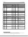
The Serial Number is set during production, and is not to be changed by the user !
The CAN Node Identifier has been set during production but can be changed if the need arises (e.g. if the
CANspy module is connected to a CAN bus where the Node Identifier already exists).
18
CANspy
v1.3 13-Mar-2009
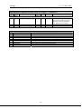
Manufacturer-specific Profile Area (CANspy)
Index
(hex)
Sub
Index
Description
Data/
Object
Attr
5C00
-
Compile-time Options
U32
RO
5E00
-
Jump to Bootloader app
U8
WO
Object 5C00: Compile Options
Bit Option
0
1
2
3
4
5
6
7
VARS_IN_EEPROM
–
–
–
–
AT90CAN32
AT90CAN64
AT90CAN128
(continued…)
Default
Comment
Bitmask denoting which compile
options were used when the application code was generated
(see table below for details)
Comment
Store/retrieve working copies of configuration parameters in/from EEPROM
–
–
–
–
Code compiled for AT90CAN32 microcontroller
Code compiled for AT90CAN64 microcontroller
Code compiled for AT90CAN128 microcontroller
19
CANspy
4.6
v1.3 13-Mar-2009
Emergency Objects
CANopen Emergency messages are triggered by the occurrence of an internal (fatal) error
situation. An Emergency CAN-message has the following general syntax:
CANspy → Host
COB-ID
Byte 0-1
080h +
Emergency
Error Code
NodeID
Byte 2
Error Register
(Object 1001h)
Byte 3-7
Manufacturer specific error field
A toggle bit is present in byte 7 of the Emergency message. Byte 7 alternates between the
values 00h and 80h from one Emergency message to the next.
The following Emergency messages can be generated by the CANspy application:
Error
Description
Emergency
Error Code
Manufacturer-specific Error Field
(byte 3-7)
(byte 1-0; hex)
CAN communication
8100
Byte 3: 00h
Byte 4: total format error count
Byte 5: error counter
Byte 6: bus-off counter (see OD index 3200, sub 3)
CAN buffer overrun
8110h
CAN message buffer in RAM full: at least 1 message was lost
Life Guarding time-out
8130
CAN-controller has been reinitialized
Switch error
5000
Byte 3: 01h
Byte 4: 0 if only ‘LED Open Detection’ flag set,
1 if ‘Temperature Error’ flag set
CRC error
5000
Byte 3: 30h
Byte 4: 1 (program FLASH)
EEPROM: write error
5000
EEPROM: read error
5000
Byte 3: 41h
Byte 4: Parameter block index 1
Byte 5: 0 : writing block info
> 0: size of parameter block to write
Byte 3: 42h
Byte 4: Parameter block index 1
Byte 5: Error id (1=CRC, 2=length, 4=infoblock)
…table continues on the next page…
1
0: ---, 1: Guarding parameters, 2: ---, 3: ---, 4: ---, 5: ---, 6: CAN configuration parameters, 7: ---,
FFh: CANspy Serial Number.
20
CANspy
v1.3 13-Mar-2009
Error
Description
Emergency
Error Code
Manufacturer-specific Error Field
(byte 3-7)
(byte 1-0; hex)
Irregular reset (Watchdog,
Brown-out or JTAG)
5000
Byte 3: F0h
Byte 4: microcontroller MCUSR register contents 1
Bootloader: not present
5000
Byte 3: F1h
Bootloader is now in control 2
5000
Bootloader cannot jump to
application: invalid 2
6000
Byte 3: FEh
Byte 4: 80h
Byte 5: 64h
Byte 6: microcontroller MCUSR register contents 1
Byte 3: FEh
Byte 4: AAh
Byte 5: AAh
Byte 2 of the Emergency message contains the value of the socalled Error Register (Object
Dictionary index 1001h, a mandatory CANopen object). One or more bits of the 8-bit Error
Register can be set to 1, depending on the node's history of errors since the last reset. The table below gives a description of the different bits.
Error Register (Object 1001h) bits
Bit
0
1
2
3
4
5
6
7
1
2
Error type
generic
current
voltage
temperature
communication
device profile specific
reserved (=0)
manufacturer specific
AT90CAN64 MCUSR register bits: 01h: Power-On Reset, 02h: External Reset, 04h: Brown-Out Reset,
08h: Watchdog Reset, 10h: JTAG Reset.
This Emergency message is generated by the Bootloader program !
21
CANspy
v1.3 13-Mar-2009
References
[1] H.Boterenbrood,
CANopen, high-level protocol for CAN-bus,
Version 3.0, NIKHEF, Amsterdam, 20 March 2000.
http://www.nikhef.nl/pub/departments/ct/po/doc/CANopen30.pdf
[2] CAN-in-Automation e.V.,
CANopen, Application Layer and Communication Profile,
CiA DS-301, Version 4.0, 16 June 1999.
[3] H.Boterenbrood,
CANopen Bootloader for the ELMB ATmega128 microcontroller,
Version 1.1, NIKHEF, Amsterdam, 10 March 2004.
http://www.nikhef.nl/pub/departments/ct/po/html/ELMB128/ELMBbl-doc.pdf
22