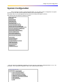
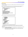
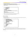
1
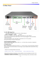
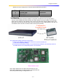
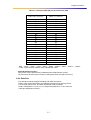
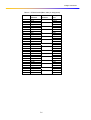
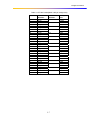
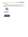
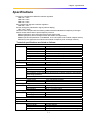
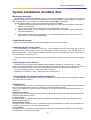
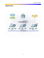
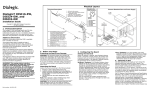
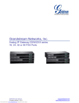
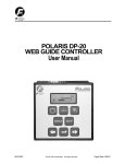
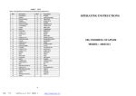
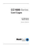
USER MANUAL
ETU-05
16/30 Channel
E1 Voice Multiplexer
Version 1.0
2004/06
Table of Contents
Chapter 1. Introduction……………………………………….
Chapter 2. Features……………………………………………
Chapter 3. Specifications…………………………………….
Chapter 4. Installation and Boost Test…………………….
Chapter 5. System Configuration…………………………..
Chapter 6. Application………………………………………..
Appendix A Accessories List………………………………..
Table of Contents
Chapter 1 Introduction
Introduction
Utilizing advanced digital time-division multiplex technology, the ETU05, E1 voice multiplexing device,
can connect up to 30 user exterior line with one E1 channel in a 1U standard rack mountable case, and can
be cascaded according to user capacity. The device has call-in/call-out bi-directional communication function,
user-circuit inversing cost counter function, and a datacom interface. (can connect with user data interface
(V.35 or R350)), for comprehensive access of voice and data. E1 interface is compliant with ISDN PRI
standard. D channel signaling interface is compliant with ISDN Q921/Q931 30B+D subset (compliant with
GBYDN 034.1-034.4). This device has self-diagnosis and remote maintenance function, can perform
centralized remote surveillance, alert, configuration, management and maintenance of all online ETU05
E1voice multiplexing devices through a centralized network administrative system.
With the ETU05, operators can conveniently provide caller cost counting, user loop inverse cost counting,
billing card, prepaid card, IP public telephone (Internet telephony service provider), IP service and dataaccess service business etc…
The ETU05 has several distinct features, including compact-size, low-cost, maintenance-free, easy
installation, cascaded solution, remote centralized management and is an ideal choice for operators!
1-1
Chapter 1 Introduction
This page is left in blank intentionaly
1-2
Chapter 2 Features
Features
2.1 Description
The ETU05 pictured below is built in a 19-inch 1U standard case. It may be placed on a desktop or
installed in a rack. The ETU05 is available in either AC power or DC –48V version.
Figure 2 Overview of ETU05 E1 voice multiplexing device
2.2 Ordering Information
Note: you can check the ETU05 firmware version in terminal mode after boot.
2.3 Front Panel
"Power" LED: Indication of the power system's status (Green indicates the unit status is normal);
"System" LED: Indication of the system operation status (Green indicates the status is normal, red
indicates for alert);
"Signal" LED: Indication of E1 loop signal status (Green indicates the status is normal, red indicates for
alert);
"Sync" LED: E1 loop synchronous status (Green indicates the status is normal, red indicates for alert);
"Link" LED: System's linking status (Green indicates the status is normal, red indicates for alert);
"Data" LED: Indicates the data communication (send and receive) status
(when LED is flashing, it indicates the data is transmitting)
"L1"-"L32" LED: Indicates the status of each (loop) user status (pick up/hang up).
(when LED is flashing, it indicates the user is processing the phone call).
2-1
Chapter 2 Features
2.4 Rear Panel
2.4.1 E1-PRI Signal Port
75Ω unbalanced interface: 2 BNC connectors, HDB3 code type
120Ω balanced interface: RJ45
1=RXTIP
2=RXRING
3=TXTIP
4=TXRING
If E1 circuit use unbalanced mode 75Ω (SW#1, all dip switch turn to "ON" position)
Then the PRI interface connects to BNC socket, on the rear panel tagged TX, RX to individually
denote two directions.
If E1 circuit use balance mode 120Ω (SW#1, all dip switch turn to "OFF" position)
Then the PRI interface connects to RJ45 socket.
2.4.2 Terminal Control Port
Terminal control interface (DB9, RS-232, DCE, N, 8, 1, no flow control), can perform configuration
setting and status monitor.
2.4.3 Billing Port
Billing counter interface (DB9, RS-232, DCE, N, 8, 1, no flow control), can output the billing information.
The first format is the same as Siemens 315 exchanger, output a telephone bill data information string
after each call.
Siemens 315 exchanger telephone bill format:
06.08.02 21:19:38 13 8020
00:00:29 07553170818
//this is the output bill of exchanger
Date(8) Blank(1)starting time(8) Blank(1) Relay(3) Blank(1) Extension(6) Blank(7) Duration of the
call(8) Blank(1) Telephone number//Note
The definition of educed circuit of terminal interface and CDR billing interface are listed as follows:
2-2
Chapter 2 Features
Definition list of pin-assignment of terminal interface/CDR billing interface
PIN
2
3
5
Definition
RD(104) RXD
TD(103) TXD
SG(102) Ground
Direction
Device out
Device in
——
2.4.4 Data Port
A V.35 or RS-530 data connector is added, it can perform the data and voice synchronization
function via the installed N64-FSK interface card. Data interface connector: DB25/ V.35 or RS-530
(select from the jumper on the interface card), connect one side of the cable to DB25 socket on the
back panel, and connects the other side to the user data device. Test of data interface: The user can
use interface loop to test the connection status. See picture for details:
The configuration setting of data port are as below :
1) It can be processed by configured E1 time-slot occupied as the data port
(1 time slot corresponds 64Kbps)
2) It can also be processed by setting V.35 or RS-530 as the data port, just set the dip switch on
the PCB board to the corresponding position, see as follows:
Data interface card
SW1, SW9, SW5 all short circuited to above and set as V.35,
SW1, SW9, SW5 all short circuited to bottom and set as RS-530;
The factory default setting is configured as V.35.
2-3
Chapter 2 Features
The data port cable pin assignment is as below
Table 2.2
Data port & V.35 port I/F connection table
DB25-M Connector
V.35-F34 Connector
1
7
2
14
3
16
4
5
6
20
8
24
11
15
12
17
9
A
B
P
S
R
T
C
D
E
H
F
U
W
Y
AA
V
X
Note :"2&14";"3&16";"24&11";"15&12";"17&9" These five pairs need to use the twisted pair cable.
2-4
Chapter 2 Features
Table 2.3 Data port & RS-530 port I/F connection table
DB25-M Connector
DB25-F Connector
1
7
2
14
3
16
4
19
5
13
6
22
20
23
8
10
24
11
15
12
17
9
1
7
2
14
3
16
4
19
5
13
6
22
20
23
8
10
24
11
15
12
17
9
Note :"2&14";"3&16";"4&19";"5&13";"6&22";"20&23";"8&10";"24&11";"15&12";
"17&9". These ten pairs need to use the twisted pair cable.
Caller ID Display Function :
This function can be performed by installed the N64-FSK interface module.
The user will receive the phone number of calling party after received the first ring.
2.4.4 Data Port
FXS interface module supports the billing and caller-id functions.
Feed-in loop current 25mA/4Km, the interface will be driven by the ring current.
For 32 loops channel user, two DB44 twisted-pair cable is needed.
Port#1 corresponds L1~L8 & L17~L24, Port#2 corresponds L9 ~L16 & L25~L32.
Cable pin assignment as below :
2-5
Chapter 2 Features
Table 2.4 ETU05 Port#1(DB44 cable pin assignment)
DB44 Pin Call-out
definition
16
TIP1
1
Ring1
18
TIP2
3
Ring2
20
TIP3
5
Ring3
22
TIP4
7
Ring4
24
TIP5
9
Ring5
26
TIP6
11
Ring6
28
TIP7
13
Ring7
30
TIP8
15
Ring8
31
TIP17
32
Ring17
17
TIP18
2
Ring18
19
TIP19
4
Ring19
21
TIP20
6
Ring20
23
TIP21
8
Ring21
25
TIP22
10
Ring22
27
TIP23
12
Ring23
29
TIP24
14
Ring24
Inner call
definition
L1
L2
L3
L4
L5
L6
L7
L8
L17
L18
L19
L20
L21
L22
L23
L24
2-6
Correspond
color
White
Orange
White
Blue
White
Green
White
Brown
White
Grey
Black
Orange
Black
Blue
Black
Green
Black
Brown
Black
Grey
Red
Orange
Red
Blue
Red
Green
Red
Brown
Red
Grey
Yellow
Blue
Chapter 2 Features
Table 2.5 ETU05 Port#2(DB44 cable pin assignment)
DB44 Pin Call-out
definition
16
TIP9
1
Ring9
18
TIP10
3
Ring10
20
TIP11
5
Ring11
22
TIP12
7
Ring12
24
TIP13
9
Ring13
26
TIP14
11
Ring14
28
TIP15
13
Ring15
30
TIP16
15
Ring16
31
TIP25
32
Ring25
17
TIP26
2
Ring26
19
TIP27
4
Ring27
21
TIP28
6
Ring28
23
TIP29
8
Ring29
25
TIP30
10
Ring30
27
TIP31
12
Ring31
29
TIP32
14
Ring32
Inner call
definition
L9
L10
L11
L12
L13
L14
L15
L16
L25
L26
L27
L28
L29
L30
L31
L32
2-7
Correspond
color
White
Orange
White
Blue
White
Green
White
Brown
White
Grey
Black
Orange
Black
Blue
Black
Green
Black
Brown
Black
Grey
Red
Orange
Red
Blue
Red
Green
Red
Brown
Red
Grey
Yellow
Blue
Chapter 2 Features
2.4.6 Power Supply
A standard IEC 3-prong receptacle, located on the rear of the unit. In the AC model,
100~240VAC (self-adjustable); in the DC model, 36~72VDC is connected to the lower terminal
block, observing the proper polarity. The ETU05 should always be grounded through the
protective earth lead of the power cable in AC installations, or via the ground connection for DC
installations.
Left: Live line
Right: Natural line
Middle: Ground
+
-
≣
≣ stands for the "grounded".
2-8
Chapter 2 Features
This page is left in blank intentionaly
2-9
Chapter 3 Specification
Specifications
This device complied with ISDN-PRI interface regulation
YDN 034.1-1997
YDN 034.2-1997
YDN 034.3-1997
YDN 034.4-1997
Also complied with signal #1 interface regulation
YDN 065.1-1997
And the calling party identification signal (caller id display)
YD/T 1277.1-2003
This device also complied with the following related industrial standards for telephony exchanger
network access examination of public telephony network:
GB3378 (Telephony auto-exchange network user signal mode)
GB3380 (Telephony auto exchange network bell stream and signal tone)
GB6879 (Technical specification of 2048Kbit/S, 30 circuit impulse code modular multiplex device)
GB/T5444 (User signal technical indices test method of telephony auto exchange network)
Technical specifications are listed as follows:
E1 Circuit
Frame format:
CCS(PCM31)/CAS(PCM30)
Bit rate:
2.048Mb/s
Line code:
HDB3
Incept sensitivity:
-20/-43Db
Circuit:
75Ω (non-balance) /120Ω (balance)
“Impulse” rage:
Standard 2.37V(75Ω)
Range of Jitter tolerance: complied with ITU G.823, jitter attenuator installed
Standards
G.703, G.704, G.732, G.823
E1 System clock
Recovery clock:
From E1 receiving signal
Internal clock:
2.048Mb/s±50ppm
User line interface
Line impedance:
600Ω
Feedback current:
25mA
Wire length
Over than 4 Km
The connector for the phone wire has electronic inducted protection and lightning
strike surge protection
Bell stream parameter: Effective value 90V, 25Hz
Data interface
Interface type
V.35, RS-530/RS-449/X.21
Data rate
N x 64Kbps
Monitoring / Billing interface
Protocol:
RS-232 (DCE)
Rate:
9600 bps
Configuration
N, 8, 1, non flow control
Power supply
AC supply:
100~240 VAC,45~63Hz
DC supply:
36~72 VDC
Power consumption:
< 50W
LED indication
Alarm, Loop status , Power
Physical indices
Case:
1U 19 inch standard case
Size (H×W×D):
45×440×380mm
Weight:
5.1Kg
Working condition:
Temp 0~40oC Humidity 0~90% non-condensing
3-1
Chapter 3 Specification
This page is left in blank intentionaly
3-2
Chapter 4 Installation and Boot Test
System Installation and Boot Test
Mechanical assembly
The ETU05 is designed for tabletop, shelf or rack mount installation, and except for rack mount
installation, is delivered completely assembled. Rack mounted applications require installation of additional
rack mounting “ears”. No provisions are made for bolting the ETU05 to the tabletop.
The following procedure will offer you the idea about hardware installation :
1. Loosen the each two screws on the left and right sides of the front panel: altogether 4 bolts (3X4),
rotate the unit afterward
2. Then go for the upper panel, loosen all the screws, altogether 4 bolts (3X4)
3. After the upper panel, you can reconfigure the DIP switch SW1 on the main board to configure the
E1 channel impedance.
4. After installation each panels, if necessary, you can install the fixed bracket on the side, two earpanels to fix on each side (3X6)(attached).
Connecting the power
Before you connects the power cable, please make sure the power is shut down.
Connecting the E1 loop channel
If E1 channel loop is in unbalance mode 75Ω.(which indicates that DIP switch SW1 are all on the
position of "ON")Then please connect the PRI interface to BNC connectors. If E1 channel loop is in
balance mode 120Ω.(which indicates that DIP switch SW1 are all on the position of "OFF")Then connect
the PRI interface to RJ45 connector.
If test purpose is for single unit self-test, user may loop-back E1 channel, this way, the "link" LED will ight
in red.
Connecting the voice channel
The phone cable wire gauge uses standard 0.4mm diameter, twisted-pair, 2 meters long, or custommade. If channel/loop indicator on the front panel lights, which means the phone cable connection is ok and
the status is normal. With this method, the user can easily tell which channel/loop is occupied or not.
For 32 channels/loops system, it needs two DB44 connectors,
PORT#A for L1-L8 and L17-L24,PORT# B for L9-L16 and L25-L32.
Connecting the PC serial port with terminal port
Use attached DB9 straight cable to connect PC, Within this, the system can perform configuration setting
and system device monitoring.
Operation test
After switch on the power, user can easily tell the device is under the normal status by the LED indicator.
After connecting the power cord, then connecting E1 cable and telephone cable.
If the "Power" LED is on, it indicates power module is ok, the other way indicates the power module is out
of service. .
System device status:
If it lights in red, it indicates system is out of service, the other way it will light in green, means it passes the
self-test and the status is normal.
E1 circuit status:
If it lights in green, it indicates the E1 signal is proceed the transmitting, the other way it will light in red, it
means no transmitting at;
Synchronization status:
If it lights in green, it indicates the E1 circuit frame is under synchronization, the other way it will light in red,
it means E1 circuit frame is not under synchronization;
Link indication:
If it lights in green, it indicates the loop signal link is connected, the other way it will light in red, it indicates
loop signal link connecting status failed.
4-1
Chapter 4 Installation and Boot Test
Notice: If test purpose is for single unit self-test, user may loop-back E1 channel, this way, the "link" LED
will light in red.
4-2
Chapter 4 Installation and Boot Test
After all the configuration setting and tests which mentioned above, the PC terminal should displays
special message as follows:
TEST...OK+OKC
CALLING
TEST ROM OK
TEST RAM OK
TEST FPGA OK
E1 LINE SET OK
TEST SWITCH LINK OK
VOICE CHANNEL SET OK
LOAD CALLING NUMBER OK.
INITIALIZE CALLER NUMBER LIMIT.
LOAD ACCESSING NUMBER OK.
LOAD PASSWORD OK.
INITIALIZE CARD NUMBER.
LOAD CARD PIN OK.
LOAD AREACODE OK.
LOAD NM ADDRESS OK.
ETU-05C VER 1.06.445566
DATAPORT:
ACTIVE:DISABLE
LOOP:NO LOOP
CLOCK:INTERNAL CLOCK
TIMESLOT:NULL
CDR: CDR MODE 1
NET MANAGER:
TIMESLOT: 0
ADDRESS:02.00.00
The above message indicate the system is operating in the normal, the user may
start to run the system for functional test.
4-3
Chapter 5 System Configuration
System Configuration
After connecting of power cord and the DB9 cables, you can start to set the configuration for system
operation. (You can also connect telephone cable for the communication test)
The system will run the self-diagnosis test first, then the message will display as follows
After passing the self-diagnosis, displays as follows:
TEST...OK+OKC
CALLING
TEST ROM OK
TEST RAM OK
TEST FPGA OK
E1 LINE SET OK
TEST SWITCH LINK OK
VOICE CHANNEL SET OK
LOAD CALLING NUMBER OK.
INITIALIZE CALLER NUMBER LIMIT.
LOAD ACCESSING NUMBER OK.
LOAD PASSWORD OK.
INITIALIZE CARD NUMBER.
LOAD CARD PIN OK.
LOAD AREACODE OK.
LOAD NM ADDRESS OK.
ETU-05C VER 1.06.445566
DATAPORT:
ACTIVE:DISABLE
LOOP:NO LOOP
CLOCK:INTERNAL CLOCK
TIMESLOT:NULL
CDR: CDR MODE 1
NET MANAGER:
TIMESLOT: 0
ADDRESS:02.00.00
After E1 channel is established completely, the user may key in the factory default password "111111" for
the system. Then it prompts configuration main menu window listed as follows:
DATE LINK SET OK
PASSWORD : ******
<< MAIN MENU >>
1. SET CALLER NUMBER
2. SET ACCESSING NUMBER
3. DISPLAY CALLER NUMBER
4. DISPLAY ACCESSING NUMBER
5. SET SYSTEM
6. SET DATA PORT
0. EXIT
5-1
Chapter 5 System Configuration
The user may enter the option on the menu listing for detail configuration setting. Among these options, the
option#6 will be invalid if the data port interface is not installed. (Detailed in the following pages).
5-2
Chapter 5 System Configuration
Set Caller Number:
After the user enter "1" for the option on the main menu, the system will prompt another message to
indicate for the detail setting for this function.
First, the user need to input the caller access (1-32) which desired to set.
Here is an example, user can following the setting as this one.
Example:
Enter "1" for the line#1 and then press "enter".
Input caller number: e.g 88888888, then confirm it by enter the same number again. (line 01: 88888888)
After system confirmation, it prompts to input the next caller number to be set.
<< MAIN MENU >>
1. SET CALLER NUMBER
2. SET ACCESSING NUMBER
3. DISPLAY CALLER NUMBER
4. DISPLAY ACCESSING NUMBER
5. SET SYSTEM
6. SET DATA PORT
0. EXIT
SELECT? 1
<<
SET CALLER NUMBER >>
INPUT LINE NUMBER (1- 32) : 1
INPUT CALLING NUMBER :88888888
LINE 01 : 88888888
INPUT LINE NUMBER (1- 32) :
User can press "Esc" key to return to the main menu
If you wish to browse all the caller number, the user can press "3" for the option on the main menu.
<< MAIN MENU >>
1. SET CALLER NUMBER
2. SET ACCESSING NUMBER
3. DISPLAY CALLER NUMBER
4. DISPLAY ACCESSING NUMBER
5. SET SYSTEM
6. SET DATA PORT
0. EXIT
SELECT? 3
<<
DISPLAY CALLER NUMBER
>>
LINE 01 : 88888888
LINE 02 : (NULL)
LINE 03 : (NULL)
LINE 04 : (NULL)
LINE 05 : (NULL)
LINE 06 : (NULL)
LINE 07 : (NULL)
LINE 08 : (NULL)
LINE 09 : (NULL)
LINE 10 : (NULL)
LINE 11 : (NULL)
LINE 12 : (NULL)
LINE 13 : (NULL)
LINE 14 : (NULL)
LINE 15 : (NULL)
LINE 16 : (NULL)
LINE 17 : (NULL)
LINE 18 : (NULL)
LINE 19 : (NULL)
LINE 20 : (NULL)
LINE 21 : (NULL)
LINE 22 : (NULL)
LINE 23 : (NULL)
LINE 24 : (NULL)
LINE 25 : (NULL)
LINE 26 : (NULL)
LINE 27 : (NULL)
LINE 28 : (NULL)
LINE 29 : (NULL)
LINE 30 : (NULL)
LINE 31 : (NULL)
LINE 32 : (NULL)
5-3
Chapter 5 System Configuration
As the message display above, you may see the line#1 caller number has been modified.
5-4
Chapter 5 System Configuration
Set Access Number:
After the user enter "2" for the option on the main menu, the system will prompt another message to
indicate for the detail setting for this function.
1.
2.
3.
Input line number according to system prompt (1-32)
Input access number: Example: Input "17910" and press "enter" key to confirm.
System will prompt the another line number to be set, the user can press "Esc" key to return to main
menu
<< MAIN MENU >>
1. SET CALLER NUMBER
2. SET ACCESSING NUMBER
3. DISPLAY CALLER NUMBER
4. DISPLAY ACCESSING NUMBER
5. SET SYSTEM
6. SET DATA PORT
0. EXIT
SELECT? 2
<<
SET ACCESSING NUMBER
INPUT LINE NUMBER (1- 32) : 1
INPUT ACCESSING NUMBER : 17910
LINE 01 : 17910
INPUT LINE NUMBER (1- 32 ) : _
>>
Display access number:
User can press "Esc" key to return to the main menu
If you wish to browse all the caller number, the user can press "4" for the option on the main menu.
6. SET DATA PORT
0. EXIT
SELECT? 4
<<
DISPLAY ACCESSING NUMBER
>>
LINE 01 : 88888888
LINE 02 : (NULL)
LINE 03 : (NULL)
LINE 04 : (NULL)
LINE 05 : (NULL)
LINE 06 : (NULL)
LINE 07 : (NULL)
LINE 08 : (NULL)
LINE 09 : (NULL)
LINE 10 : (NULL)
LINE 11 : (NULL)
LINE 12 : (NULL)
LINE 13 : (NULL)
LINE 14 : (NULL)
LINE 15 : (NULL)
LINE 16 : (NULL)
LINE 17 : (NULL)
LINE 18 : (NULL)
LINE 19 : (NULL)
LINE 20 : (NULL)
LINE 21 : (NULL)
LINE 22 : (NULL)
LINE 23 : (NULL)
LINE 24 : (NULL)
LINE 25 : (NULL)
LINE 26 : (NULL)
LINE 27 : (NULL)
LINE 28 : (NULL)
LINE 29 : (NULL)
LINE 30 : (NULL)
LINE 31 : (NULL)
LINE 32 : (NULL)
5-5
Chapter 5 System Configuration
System Setting:
Press "5" for the option on the main menu to configure the system then the another options for this function
will be display as follows
Press “1” for the option to set password, then the system will allow the user to input new password, and
again to confirm it. New password will be saved as the current password after system verification.
SELECT? 5
<<
SET SYSTEM >>
1. SET PASSWORD
2. SET CDR
3. SET DEFAULT
0. EXIT
SELECT ? 1
<<
SET PASSWORD >>
OLD PASSWORD: ******
NEW PASSWORD: ******
ENTER NEW PASSWORD AGAIN : ******
NEW PASSWORD SAVED .
Press “2” for the option to set CDR (cost billing) detail configuration
<< SET CDR >>
1. CDR MODE 1
2. CDR MODE 2
3. CDR OFF
0. EXIT
CURRENT : OFF
SELECT? 2
<<
SET CDR >>
1. CDR MODE 1
2. CDR MODE 2
3. CDR OFF
0. EXIT
CURRENT : CDR MODE 2
SELECT ? _
The message will indicate the current status for CDR function. which is the “open” status, through
corresponding selection to reconfigure CDR status. After setting complete, press "0" key to return to
previous menu.
CDR mode 1: The billing output message format is according the Siemen 315 PABX format, it is compatible
with the 3rd party billing software.
CDR mode 2: The billing system is installed the "IP phone billing system", it can be connect with the
business calculator to handle the detail information. As "how to use the IP phone", please
check the reference manual or installation.
5-6
Chapter 5 System Configuration
On the following option menu
Press ”3” key to reset all modified values back to default setting
Reset default value is to completely earse all caller number and access number,
Close billing function and reset password to factory default setting.
Displays as follows:
<< SET SYSTEM >>
1. SET PASSWORD
2. SET CDR
3. CDR DEFAULT
0. EXIT
SELECT? 3
<<
SET DEFAULT >>
ALL DATA WILL BE DELETED ! ARE YOU SURE(Y/N) ?
Y
PLEASE WAIT …
ALL DATA HAVE BEEN SET TO DEFAULT .
Press "0" key for the option, you may go back the main menu
Data Port Setting:
Press "6" for the option on the main menu to configure the system then the another options for this function
will be display as follows
<< SET SYSTEM >>
1. SET CALLER NUMBER
2. SET ACCESSING NUMBER
3. DISPLAY CALLER NUMBER
4. DISPLAY ACCESSING NUMBER
5. SET SYSTEM
6. SET DATAPORT
0. EXIT
SELECT? 6
<<
SET DATAPORT >>
1. ACTIVE
2. TIMESLOT
3. CLOCK
0. EXIT
SELECT ? _
Option#1 is to active the data port, otherwise any function of data port will be closed. The user may
press "1" or "2" to disable or enable the data port. By press the "0" key here, you may return to the previous
option menu.
5-7
Chapter 5 System Configuration
Option#2 is to set the configuration of timeslot. "NULL" indicates that this timeslot is available for
current setting. You may learn the input value timeslot format as display as follow:
<<
SET DATAPORT >>
1. ACTIVE
2. TIMESLOT
3. CLOCK
0. EXIT
SELECT ? 2
<< SET DATA PORT TIMESLOT >>
CURRENT TIMESLOT : NULL
INPUT TIMESLOT :5,3,8-10
UPDATE TIMESLOT : 5,3,8-10
By press the "0" key here, you may return to the previous option menu.
Option#3 is to set the configuration of E1 loop. The user may press "1" or "2" to disable or enable the E1
loop function display as follow:
3. LOOP
4. CLOCK
0. EXIT
SELECT ? 3
<< SET LOOP >>
1. NO LOOP
2. LOOP
0. EXIT
CURRENT : NO LOOP
SELECT : 2
<< SET LOOP >>
1. NO LOOP
2. LOOP
0. EXIT
CURRENT : LOOP
SELECT : _
By press the "0" key here, you may return to the previous option menu.
5-8
Chapter 5 System Configuration
Option#2 is to set the configuration of timeslot. "NULL" indicates that this timeslot is available for
current setting. You may learn the input value timeslot format as display as follow:
3. LOOP
4. CLOCK
0. EXIT
SELECT ? 4
<< SET CLOCK >>
1. INTERNAL CLOCK
2.
EXTERNAL CLOCK
0. EXIT
CURRENT : INTERNAL CLOCK
SELECT : 2
<< SET CLOCK >>
1. INTERNAL CLOCK
2.
EXTERNAL CLOCK
0. EXIT
CURRENT : EXTERNAL CLOCK
SELECT : _
By press the "0" key here, you may return to the previous option menu.
At this moment, you have already completed all the menu setting, the user may exit the
setting by press "0" key on the main menu.
5-9
Chapter 5 System Configuration
This page is left in blank intentionaly
5-10
Chapter 6. Application
Application
6-1
Chapter 6. Application
.
6-2
Appendix A. Accessories list
Item
Name
Q'ty
1
Ear Panel for Rack Mount Kit
2
2
HD44M-RJ11*16 Cable
2
3
DB9M/DB9F Cable
1
4
AC Power Cord
1
A-1
Remark
Appendix A. Accessories list
This page is left in blank intentionaly
A-2
ETU05 16/30 Channel
E1 Voice Multiplexer