1
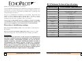
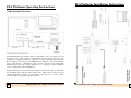
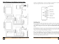
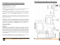
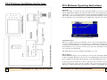
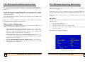
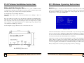
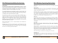
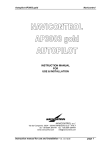
NMEA 0183 (ver 2.0) Accepted Input Sentences
Formatter
BWC
BWR
DBT
DPT
GGA
GLL
RMA
RMB
RMC
VHW
VLW
VTG
ZDA
Description
Bearing and Distance to Waypoint
Bearing and Distance to Waypoint, Rhumb Line
Depth Below Transducer
Depth
Global Positioning System Fix Data
Geographic Position, Latitude/Longitude
Recommended Minimum Specific Loran-C Data
Recommended Minimum Navigation Information
Recommended Minimum Specific GPS/TRANSIT Data
Water Speed and Heading
Distance Travelled through the Water
Track Made Good and Ground Speed
Time and Date
Professional
Forward Looking Sonar
♦ FLS Platinum
Video Engine
NMEA 0183 (ver 2.0) Output Sentences
All sentences accepted by the FLS Platinum are also output.
Depth & log sentence information output from the unit will depend on the depth and log source selected. If
the depth & log sources are set to local, then the depth and log sentences output will be the internally calculated depth/log data.
Instruction Booklet
Sentences are output at 2 second intervals.
TM
We hope you enjoy using your EchoPilot FLS Platinum
WE ARE ALWAYS PLEASED TO TALK TO OUR CUSTOMERS.
Information in this document is subject to change without notice. No part of this document may be
reproduced or transmitted in any form or by any means, electronic or mechanical, for any purpose, without
the express written permission of EchoPilot Marine Electronics Ltd.
ECHOPILOT MARINE ELECTRONICS LTD
Copyright © 2006 by EchoPilot Marine Eletronics Ltd. All rights reserved.
1 Endeavour Park, Crow Arch Lane, Ringwood,
Hampshire, United Kingdom. BH24 1SF.
Telephone: 01425 476211/2
Fax: 01425 474300
Protected by USA Patent 5530680 and European (UK) Patent 0624253
E-Mail: [email protected]
Webpage: www.echopilot.com
Author: Paul Beeston (Chief Dogs Body)
Last Updated: 24.01.2008
For up to date information and advice, please telephone, browse our Website, or send
us an E-Mail.
32
e-mail: [email protected]
website:
www.echopilot.com
FLS Platinum
Video Engine Instruction Manual
FLS Platinum Video Engine Instruction Manual
1
TM
FLS Platinum Technical Specifications
Thank you for purchasing this Echopilot instrument.
Your new EchoPilot instrument has been manufactured to the highest standards by the
dedicated staff of a company with many years of experience in marine electronics. You
have invested in the most up to date technology available and in a product rigorously
tested in the laboratory and at sea.
All goods of our manufacture are backed by a 2 year warranty. Expert advice and
guidance is always available by Telephone (01425) 476211 - just ask for customer
service. If you are outside the UK you can still call us or any of our overseas
distributors. We welcome the opportunity to talk to our customers.
Nobody enjoys reading manuals, but please continue to read this one! Installing
your instrument correctly is vital to get the maximum performance, pleasure and
safety from your equipment, so please take the time to read the instructions.
Please observe the following warnings:
Please do not cut the transducer cables - they are fine multi-core cable matched to
the transducer.
Please do not remove the transducer plug from its cable - if a hole is too small
make the hole bigger! Any join in the cable will reduce sensitivity / performance.
Disclaimer
Specification
FLS Platinum Video Interface
Voltage
12v or 24v DC
Current Consumption
Video Interface Box - 300mA
Transmitter Box - 50mA
Operating frequency
200 kHz
Forward Range
20 to 200 metres
Maximum Depth Range
10 to 100 metres
Display Update
Rates
1-2 updates / sec
NMEA
0183 Version 2.0
Video Output
PAL Composite Video (RCA Socket)
PAL S-Video (4 pin mini-din socket)
Built-in Test Facility
Yes
Repeater Option
Yes
Alarm
Shallow
Transducers
FLS Platinum professional
Echopilot makes no warranty as to the accuracy or completeness of
data that is included or may be downloaded or used in connection
with this product, and EchoPilot disclaims any and all express,
implied or statutory warranties including the implied warranty of
merchantability and implied warranty of fitness for a particular
purpose. It is the user’s responsibility to use this product prudently.
This product is intended to be used only as a secondary aid to
navigation and must not be used for any purpose requiring precise
measurement of distance, depth, location, or topography.
2
FLS Platinum Video Engine Instruction Manual
FLS Platinum Video Engine Instruction Manual
31
FLS Platinum - Fault Finding
Contents
Some Common Faults
Operating Instructions
Video Interface or transmitter box doesn’t switch on (no display output or LEDs
lit):•
Battery not connected
•
Battery voltage too low
Transmitter box LED not flashing:•
No power to display unit or Video Interface Box not switched on
•
12m data cable not connected properly
•
Power not cleanly applied to transmitter box - re-make connection
No FLS picture on display instrument once Video Interface Box is switched on:•
Display instrument not switched on
•
Video cable not connected to display instrument
•
Display instrument not configured to show video input
Keypad doesn’t operate:•
Keypad unit not connected to Video Interface Box (or not connected properly)
No seabed visible and transmitter box LED is flashing:•
Transducer not connected (or not connected properly) - use Test Mode
•
Incorrect range selected (try using the ‘Auto’ setting!)
Poor seabed picture or excessive noise:•
Suitable range not selected (try to fill screen with seabed)
•
Poor connection of transducer
•
Battery voltage low - use Test Mode to check Tx voltage
•
Transducer mounted at an angle
•
Turbulence at transducer location
•
Interference from other 200KHz sounders (same boat or other boats)
•
Turbulence/wake from other boats
•
Polluted water or Plankton bloom (usually early summer)
•
Dirty transducer/covered with barnacles
•
Choppy sea state - can cause surface noise
30
FLS Platinum Video Engine Instruction Manual
4
Video System Overview
Switching on
Keypad Operation - Overview
Operating Modes
Changing the Unit Settings
Operating a Repeater Unit
4
5
6
6
12
16
How FLS Technology Works
17
Some Guidance on Use
18
Installation Instructions
19
Transducer Installation
Fitting the Video Interface Box
Fitting the Keypad
Fitting the Transmitter Box
Video System Configurations
Applying Power
Maintenance
Wiring Diagrams
19
22
23
23
24
25
25
26-29
Fault Finding
30
Technical Specification
31
FLS Platinum Video Engine Instruction Manual
3
FLS Platinum Installation Instructions
FLS Platinum Operating Instructions
Video System Overview
The FLS Platinum Video Engine utilises current FLS colour sonar technology and
provides a video signal output for integrating Forward Looking Sonar into other
manufacturer’s displays (that have a composite or s-video input). The Video Interface
Box can either be used as part of the Platinum Video Engine to use another manufacturer’s single display, or alternatively can be used as a repeater for an existing FLS
Platinum system (the video display will then act as a repeater). See the installation
section for different system configurations.
The Transmitter Box is located near the transducer and the data cable provided links
the Transmitter Box with the Video Interface Box which will be located near the
chosen manufacturer’s display. A video cable (composite video or s-video) outputs
the FLS display to the chosen display instrument.
4
FLS Platinum Video Engine Instruction Manual
FLS Platinum Video Engine Instruction Manual
29
FLS Platinum Installation Instructions
Operation of the FLS functions on the chosen display are performed by a separate
keypad unit supplied and will be located near the display instrument.
Keypad Unit
Switching On
The user should ensure that both the display unit is switched on and power is applied
to the transmitter box (via a switch). Also ensure that one of the video outputs of the
Video Interface Box is connected to the video input of the display unit. The display
must then be configured to view the video signal from the FLS Platinum Video
system.
The FLS Platinum is switched on by pressing and holding the power key until a single
beep is heard. The unit will then display the introduction screen that includes the unit
software version, shortly followed by the FLS sonar display.
The sonar data displayed on the screen will depend on the sea bed below the
transducer. The unit will always switch on in ‘Auto Range’ mode which means that if
a good seabed signal is received, a suitable range will be chosen for the current depth.
Pressing the up or down arrows will turn off auto mode and the user will now have
control of the range with the up and down arrows.
28
FLS Platinum Video Engine Instruction Manual
FLS Platinum Video Engine Instruction Manual
5
FLS Platinum Installation Instructions
FLS Platinum Operating Instructions
Keypad Operation - Overview
Power Key: Switches the unit on and off.
Menu Key: Selects the menu which allows the user to modify the unit settings. See the
section Changing the Unit Settings for more information on the menu.
Up/Down Keys: When in FLS Mode (sonar data displayed), changes the sonar range
up or down accordingly. When in the menu, the up and down arrows change the
selected option. See the section Changing the Unit Settings for more information on
the menu.
Mode Key: Cycles between FLS mode, GPS mode and Test Mode. When in the menu,
the mode key returns the user to the current mode. See the relevant sections for more
information on each mode.
Page Key: When in FLS mode, changes the information displayed in the information
bar at the bottom of the screen. See FLS Mode section for more information. When
in Test Mode, cycles through three test screens that will aid in testing the unit and
provide diagnostic information. See Test Mode section for more information. The
page key has no effect in GPS Mode. See GPS Mode section for more information.
Operating Modes
FLS Mode
FLS Mode is the sonar operating mode that displays the sonar image of the seabed
ahead and below the transducer. There are eight forward range settings (20m, 40m,
60m, 80m, 100m, 150m, 200m and Auto) that are selectable with the up and down
arrow keys. When the upper range is reached with the up arrow (200m), a further press
puts the unit onto the ‘Auto’ range. Similarly, when the lower range is reached with
the down arrow, a further press puts the unit onto the Auto range. A press of either
arrow key while Auto is on will switch the Auto off and the user will retain manual
control of the range.
When returning to manual range, the range selected will be the last range selected by
the Auto function until the user presses an arrow key to change range.
6
FLS Platinum Video Engine Instruction Manual
FLS Platinum Video Engine Instruction Manual
27
FLS Platinum Installation Instructions
FLS Platinum Operating Instructions
Auto Range
When Auto range is selected, the range will automatically be set, based on the
current digital depth (displayed in bottom left hand corner). If the digital depth is
invalid due to a poor sonar signal (indicated by the depth figure flashing) the range
will remain on the last selected range for a valid depth. The status indicator box in
the top right hand corner of the display shows whether Auto range has been selected.
The sonar display in FLS Mode
Status Indicator Box
This box is displayed in the top right hand corner of the screen in FLS Mode and
shows that the Transmitter Box is connected and is communicating with the display
correctly. A green tick indicates a successful connection and a red cross indicates that
the transmitter box is not properly connected (no power to the transmitter box and/or
not connected to the display unit).
The status indicator also shows whether Auto Range is on or off.
History Display
The FLS Platinum displays a 15 second history to the left of the vertical line (0m line)
on the sonar display. The history plot is based on the digital depth readout and gives
the user a little more information about the shape of the seabed behind the vessel.
As the history plot is the last 15 seconds of seabed, the area of seabed covered will
depend on the speed of the vessel. For example, if the vessel speed is 5 knots (2.5
metres per second), then the history plot will cover a distance of 38m. Higher speeds
26
FLS Platinum Video Engine Instruction Manual
FLS Platinum Video Engine Instruction Manual
7
FLS Platinum Operating Instructions
FLS Platinum Installation Instructions
will give greater distances but with less accuracy.
Interference
Information Window
This is the window at the bottom of the display and displays the current depth and
other optional information. Pressing the page key will scroll through a number of
combinations of this information, the combinations also being dependent on whether
GPS or Log displays are turned off in the menu.
The possible combinations of information are:Depth Only
Depth + Echo Strength
Depth + Speed (log displays enabled)
Depth + Speed + Log (log displays enabled)
Depth + Speed + Echo Strength (log displays enabled)
Depth + GPS (GPS displays enabled)
Depth + Speed + GPS (log and GPS displays enabled)
•
•
•
•
•
•
•
Speed and log info can only be displayed if either a paddle wheel transducer is
connected to the display unit (speed through the water) or a GPS is connected to the
unit (speed over the ground). The source of the speed is selected in the menu.
Other depth sounders especially those that operate at 200 kHz must be wired so
they can be switched off if interference occurs. (This may appear as ‘submarine’ like
echoes coupled with a reduction in sensitivity).
Applying Power
When power is applied to to FLS Platinum system, 2 LEDs on the transmitter box
show the status of power and the communications link to the display unit.
The left LED shows power is reaching the box and this should be lit as soon as power
is applied to the transmitter box.
The right LED should also light upon applying power to the transmitter box. If
successful communication with the display is made, the LED will flash to show that the
display unit is in FLS Mode and that the transmitter box is receiving transmission
requests from the display. If this LED is not flashing, check that the display has power
connected and is switched on - and that the 12m data cable is connected properly at
both ends.
Maintenance
Keep transducer ‘O’ rings and locking ring thread well greased with a silicone grease.
Protect plugs and cables from chafe. Clean the transducer face regularly and check for
barnacles etc. With care, this may be done afloat. If you have never done this before,
phone us first! You may anti-foul the transducer. Avoid long term exposure of the
LCD to direct sunlight.
The GPS info box displays waypoint information if it is available from a connected
GPS. If no data is avalable or no GPS is connected, the fields are shown as above.
The Echo Strength Indicator displays the average peak strength of received echo over
the last 4 pings. The coloured bar will increase in length as the strength increases and
the colour of the bar will change at certain thresholds.
8
FLS Platinum Video Engine Instruction Manual
FLS Platinum Video Engine Instruction Manual
25
FLS Platinum Installation Instructions
FLS Platinum Operating Instructions
Power is also required for the lower transmitter box and should be supplied through an
on/off switch (not supplied) mounted conveniently near the display. Power may be 12 or
24 Volts.
If the bar is yellow, the signal is weak and there is likely to be no (or extremely poor)
seabed picture displayed.
The transmitter box draws approximately 50mA of current when power is applied,
even when the display is switched off. Therefore, power should be removed via the
switch when not in use.
An optional paddle wheel for water speed may also be attached to the 8 pin cable on the
master unit if required.
If the bar increases to green, the signal is above the acceptable threshold level to
generate a seabed picture. The picture may be slightly disappointing at this level.
If the bar increases to red, the signal is very good and the seabed picture should also
be good.
GPS Mode
Please refer to the wiring diagrams on pages 26-29 for further details on connecting up
the FLS Platinum Video Engine and transmitter box.
The GPS mode requires an external GPS to be connected and allows the user to view
GPS data such as:-
Video System Configurations
•
•
•
•
The FLS Platinum Video Engine and asscociated Video Interface Box can be used in a
number of configurations for different applications.
FLS Platinum Engine with Video Output (page 26) - used to drive a single
display with a video compatible input. It is also possible with this configuration to
drive a second display from the second video output connector if required. The
single keypad will control both displays simultaneously.
•
•
FLS Platinum Video Interface Box & Platinum Display unit (page 27) - used
as a repeater for a standard FLS Platinum display. This allows a video compatible
display to be used as a repeater.
•
Two FLS Platinum Engines with Video Output (page 28) - used to drive two
displays with video compatible inputs. The second video interface is controlled
independantly by its own keypad.
Current position (Lat/Long)
Current time (UTC + offset)
Speed and course over the ground (COG and SOG)
Waypoint info (ID, cross track error (XTE) + steer direction, range and true
bearing to waypont)
The depth is also displayed in GPS Mode.
GPS Mode data including depth
24
FLS Platinum Video Engine Instruction Manual
FLS Platinum Video Engine Instruction Manual
9
FLS Platinum Operating Instructions
FLS Platinum Installation Instructions
Test Mode
Fitting the Keypad
This mode allows the user to obtain diagnostic data about the unit should a fault occur
with the display, transmitter box or transducer. The page key scrolls between 3 test
pages.
The Keypad is designed to be mounted onto an instrument panel or bulkhead and
should be located near the chosen display instrument in order to operate the FLS
functions on the display.
A-Scan and Angle Graphs
These graphs display the sonar signal strength and associated calculated angles over a
30m range. If the depth is greater than 30m, these graphs will not show the received
seabed echo and angle of the seabed.
Two studs and knurled wheels are provided for mounting the keypad. Two 4mm holes
are required for the studs, plus a 20mm hole for the cable gland. A template is provided
showing the dimensions of the keypad (65mm x 150mm) and the mounting hole
locations.
If the keypad is required to be waterproof, silicon sealant should be used to protect the
stud and cable entries through the panel.
Fitting the Transmitter box
The transmitter box should ideally be mounted on a vertical surface, within reach of
the transducer cable (2m) and protected from excessive moisture.
Plugs and sockets
The 2m transducer cable (8 pin plug) connects to the right hand socket of the
transmitter box marked TX.
The A-Scan and Angle Graphs
The A-scan graph of a flat seabed will show a low signal level up to the depth of the
seabed and should then increase significantly to a higher lever when the sebed is
reached. This is the returned echo from the seabed. The angle graph will show angles
between 0 and 90 degrees. The angles should start at about 60-70 degrees at the seabed
depth and will decrease gradually as the range of the received echo increases (for a flat
seabed).
The up arrow key allows the user to scroll between the 3 receive channels (A-Scan
graph only). Each channel must be displaying similar A-Scan graphs for the angle to
be calculated correctly. Low or very different echo levels on any of the 3 channels will
cause poor performance of the FLS unit.
10
FLS Platinum Video Engine Instruction Manual
The pre-wired (5 pin) 12m cable is connected from the left hand socket on the
transmitter box marked OUT to the right hand socket (viewing display from the rear)
marked IN on the Platinum display unit or Video Interface Box . An optional repeater
can be connected with a second 12m cable connected to the OUT connector on the
master unit and the IN connector on the repeater unit.
The short cable for the power supply and NMEA (in and out) plugs into the centre (8
pin) socket on both the master unit and the optional repeater unit. See page 29 for
power and NMEA wiring. If NMEA is required on the Repeater unit as well, an extra
cable for carrying NMEA data from the master to the Repeater unit is also required.
FLS Platinum Video Engine Instruction Manual
23
FLS Platinum Installation Instructions
FLS Platinum Operating Instructions
Fitting the Video Interface Box
Diagnostics
This screen displays some diagnostic information about the unit. It shows the software
version of both the transmitter box and the display, the status of the communications
link with the transmitter box, the transmitter dc voltage supply and also tests the
settings memory on the display (EEPROM).
The Video Interface box is designed to be mounted onto a panel or bulkhead and has
two brackets for this purpose. It should be located in position so that the keypad (with
2m cable) can be postioned near the chosen display instrument.
See diagram below for mounting dimensions.
Important Note: Please check actual measurements before drilling to allow for
tolerances.
Two video cables are provided - one composite video cable (2m, 4 pin mini-din plug to
plug) and one s-video cable (2m, RCA plug to plug). The appropriate cable should be
used, depending on the video input of the display device. An adapter may be required
if the connector on the display instrument is of a different type (eg. composite video
can sometimes be a BNC type connector).
See the diagrams on pages 26-29 for how to connect the video box.
Diagnosic Data
‘Trans Box Comms Status’ should read ‘Connected OK’. Any other messages mean an
error has occured on the communications link with the transmitter box. If this is the
case, the user should ensure that the transmitter box has power and the data link cable
is connected securely at both ends (transmtter box and display).
‘Trans Box Tx Volts’ should read approximately 12 Volts. If the transmitter box
supply voltage is at exactly 12 Volts, then the Tx Volts should be about 9-10 Volts.
This will result in slight reduced peformance but should still perform well. If 14 Volts
or more are supplied to the transmitter box, maximum transmit power will be achieved.
Factory settings can be restored by pressing the up arrow key on this page.
Box Mounting Dimensions
22
FLS Platinum Video Engine Instruction Manual
FLS Platinum Video Engine Instruction Manual
11
FLS Platinum Operating Instructions
FLS Platinum Installation Instructions
NMEA Viewer
This page allows incoming data from a GPS or other NMEA compatible instrument to
be viewed to ensure that the NMEA connection is correct and that the appropriate
sentences are being received. 4 pages can be scrolled using the up arrow keys to view
all the sentence types that the unit can receive and whether any data is being received.
Fitting the Skin Fitting
Each line under each sentence type is in field order as specified in NMEA 0183 ver
2.0.
Changing the Unit Settings
A simple menu system allows the user to change the unit settings. Pressing the menu
key while in any of the display modes enters the menu, presenting the following page:-
A hole in the boat must be taken seriously! - If in doubt use an experienced shipwright.
•
•
•
•
•
•
3
For the Log plastic skin fitting - cut a 45 mm (1 /4") diameter hole.
1
For the Professional bronze skin fitting - cut a hole 60 mm (2 /2") in diameter.
Fit the skin fitting with reinforcing pads if needed or wedges if required to
ensure the transducer is as near to vertical as possible (fore/aft AND port/
starboard).
Use plenty of underwater sealant, but take care to clean off the thread thoroughly afterwards.
Secure with the nut on the inside. Do not use excessive force on the nut.
If the vessel will be floated before the transducer is fitted, the blanking cap
provided must be fitted to seal the skin fitting. (N.B. for our American
customers, for “skin fitting” read “thru-hull fitting”).
Safety
The transducer provided is designed to shear off (in the event of a severe impact), flush
with the hull, leaving the solid epoxy filled portion in the through hull fitting, and thus
poses no risk of water ingress.
Maximum hull thickness:
75 mm (3")
The desired menu option is chosen using the menu key. When the arrow cursor is
alongside the appropriate option, pressing the up or down arrow keys changes the
setting.
Pressing the page key presents the user with another set of options. There are 4 menu
pages:
Main Options
Display Options1
Display Options 2
Depth and Log Options
•
•
•
•
The unit will return to the sonar display after 10 seconds if no buttons are pressed
12
FLS Platinum Video Engine Instruction Manual
FLS Platinum Video Engine Instruction Manual
21
FLS Platinum Installation Instructions
FLS Platinum Operating Instructions
Sailing Boats
within that time. Alternatively, the user can return to the sonar display by pressing the
mode key.
On a fin keeled boat, alongside the keel and perhaps 60cm or 2 feet out - because
the beam is approximately 15 degrees overall in the horizontal plane, is often a
well protected position. But this is unsuitable for a winged keel or large bulb as
the signal from the transducer could impinge on these. Just forward of the keel is
an alternative, but take care when hoisting the boat in a sling!
Do not fit the transducer too far forward where it will come out of the water as the
vessel pitches. The transducer looks ahead as well as down and you need to see
what is under your boat as well as what is ahead. When manoeuvring in shallows
you will wish to know what is under the keel or rudder.
A long keel boat is harder, choose the position with the minimum angle of
deadrise (ie the flattest area) and fit the transducer with a pair of wedge shaped
chocks if necessary, so that it is as near to vertical as possible with the boat
upright. On boats with slack bilges it maybe necessary to fit the professional
transducer, even on a small vessel, because its skin fitting has more useable
thread. If the transducer leans forward the seabed will appear to slope up and if it
leans aft there maybe surface clutter.`
Choose a position with good access so that the transducer can be withdrawn for
cleaning if necessary.
Remember that sonar cannot see around corners, so stand under the boat with
your head near the proposed position. You must be able to see from your toes up
to above the horizontal ahead. If the boat has a full or deep forefoot obstructing
the view a more forward position maybe called for.
Shallow Alarm
The Shallow Alarm can be set to Off or 1m to 20m. When a certain number of echoes
occur above this setting, an alarm will sound (1 second on, 1 second off). The alarm
setting is retained after power down.
The shallow alarm is provided as a guide to warn the user that echoes are appearing
above the set level. It should be noted that in some conditions (particularly in noisy
sonar conditions) the alarm may be triggered by echoes from the sea surface (in
choppy water), or turbulence generated by other vessels. As experience is gained with
the FLS, the user should be able to identify this kind of noise.
Gain Level
The gain level controls the amount of sonar signal level accepted by the FLS. The
higher the value, the more signal will be accepted and give a stronger echo on the
display - but will also increase the amount of noise that will show. A lower value will
filter more of the signal and reduce the amount of noise - but will give a weaker echo
on the display.
Noise Filter
This setting allows the user to reduce the amount of ‘clutter’ on the sonar display. The
filter lever sets the number of times an echo must occur within a similar location
before it is displayed.
Setting the filter to off means that echoes only need to appear once in order to be
displayed. This gives much more detail and responsiveness on the display but will also
increase the amount of noise displayed (from air bubbles for example) which is more
random. The low, medium and high settings increase the filter gradually and hence
reduce the responsiveness and number of echoes displayed.
The medium setting is recommended as a starting point for most users.
Backlight Level
The backlight function is disabled in the Video Interface Box as control of ths display
unit’s brightness is performed on the display unit itself. Please refer to the display
manufacturer instructions.
20
FLS Platinum Video Engine Instruction Manual
FLS Platinum Video Engine Instruction Manual
13
FLS Platinum Operating Instructions
FLS Platinum Installation Instructions
Depth History
Allows the user to switch on or off the depth history display.
Transducer Installation
Key Bleep
Allows the user to switch on or off the key bleep
Colour Mode
6 colour modes are provided to allow a choice of colour sets to be selected by the user.
3 sets are for daytime use (light background colours) and 3 for night-time use (dark
background colours).
Echoes Colour
The echoes displayed in FLS Mode can be either strength encoded or ‘mono’. Strength
encoded echoes use colours to show strength variations between echoes - with red
being the strongest echo, then green, then yellow, then light blue for the weakest
echoes. Mono colour selects a single suitable colour that all echoes will be displayed
as, depending on the colour mode chosen.
Boat Length
Allows the user to set the displayed boat length to match their own boat (up to a
maximum of 20m).
Boat Type
3 boat types are available to the user: 2 motor boats and 1 sailing boat.
Bow Offset
This is the distance from the boat’s bow to the transducer position and allows the user
to obtain a more realistic picture of the seabed with respect to the vessel.
GPS Displays
Allows the GPS displays to be switched off in the information wndow in FLS Mode.
This reduces the number of combinations that can be cycled through.
The choice of transducer position will have a major effect on final performance so
please consider carefully all factors and if in any doubt, telephone the factory.
Motor Boats
On a small planing hull fit the transducer as far aft as reasonably possible. On a stern
drive boat (inboard or outboard) typically fit just in front of the engine(s). On a shaft
driven boat (not V drive) forward of the shaft log or stern gland, but behind the
gearbox. On larger vessels fit further forward to increase effective range.
Keep inboard of the lower spray rail if possible.
Do not fit downstream of any other through hull fittings (for example intakes, log,
toilet sea cocks etc) and choose a location with good access for withdrawing the
transducer for cleaning.
The transducer should ideally be vertical in the fore and aft plane at running trim. If it
leans forward the seabed will appear to slope up, and if it rakes aft then a degree of
surface clutter may show. Some heel to port or starboard is acceptable, to a maximum
of 5 degrees.
Avoid the temptation to fit the transducer too far forward as it may then be out of solid
water when at speed or pitching. Also remember the transducer looks down as well as
ahead, so when manoeuvring in shallow waters you may wish to see there is water for
the propellers and rudders.
Sonar cannot see around corners so before installing stand under the boat with your
head near the proposed position and check that you can see from your toes up to above
the horizontal ahead. If the boat has a full or deep forefoot and is shallow aft a forward
mounted transducer maybe necessary.
Log Displays
Allows the speed and log displays to be switched off in the information wndow in FLS
Mode. This reduces the number of combinations that can be cycled through.
14
FLS Platinum Video Engine Instruction Manual
FLS Platinum Video Engine Instruction Manual
19
Some Guidance on Use
FLS Platinum Operating Instructions
The Digital Depth Display
UTC Offset
Allows an offset to be applied to the received UTC time so that the local time can
be displayed in GPS mode.
This ADDITIONAL information (in the bottom left-hand corner) is the calculated
depth from the angle data that is received and processed by the FLS. Unlike older FLS
models, the depth can now be calculated regardless of the selected range and therefore
can be useful for the user in selecting the correct range. The depth relies on a good
quality sonar signal and care should be taken in poor sonar conditions (e.g. turbulence
from passing boats or another sounder running at the same frequency causing excessive noise). Care has been taken to prevent false depth readings in noisy sonar
conditions but cannot be guaranteed in all conditions.
Practice
When learning to interpret the screen practise with clear targets, e.g. a quay wall. Try
moving around an obstruction very gently to see what the maximum range is that
different targets become visible.
!!!!! WARNING !!!!!
If approaching a target select a range longer than you think you need. Most people
(including us!) seriously underestimate distances to quays, buoys, walls etc.
Note that going astern can push turbulence past the transducer reducing sensitivity or
sometimes obliterating all the picture so take care! Manoeuvre with the minimum use
of astern (reverse) power, especially with the propeller (on twin screw vessels) on the
side of the transducer.
Turbulence from other vessels, especially in shallow water can also adversely affect
performance. Algae (normally in spring), Plankton and pollution can all show up as
‘noise’ on the LCD screen.
Operating the FLS Platinum at Speed
Ultrasonic signals travel well through solids and liquids but are greatly attenuated in
air. It follows that a stream of turbulence and air bubbles will limit the performance of
the FLS system, or any depth system for that matter. However, if a place can be found
on the hull where there is a clear flow of water, then good results can be obtained even
at speed.
18
FLS Platinum Video Engine Instruction Manual
Language
Allows one of the currently available languages to be selected for unit operation.
Depth Source
Allows either local (FLS transducer) or NMEA to be chosen as the depth source. If
NMEA is selected, the depth data will be searched for automatically in the incoming
NMEA data.
Depth Units
Units can be set to Metres or Feet.
Depth Offset
The Depth Offset can be set from -3.0m to +3.0m. If the offset is positive, the set
offset will be added to the calculated depth below transducer to give depth below the
surface If the offset is negative, the set offset will be subtracted from the calculated
depth below transducer to give depth below the keel.
This offset only applies to the digital depth readout in the bottom left hand corner of
the display and NOT the graphical seabed picture.
Log Reset
Pressing the up or down keys will reset the current log trip distance.
Log Source
Allows either local (paddle wheel) or NMEA to be chosen as the log source. If
NMEA is selected, the speed/log data will be searched for automatically in the
incoming NMEA data. NMEA STW (speed through water) searches for speed
through water data in the approiate sentences. NMEA SOG (speed over ground)
searches for speed over ground data in the appropriate sentences.
Log Units
Units can be set to either Knots, KPH or MPH.
FLS Platinum Video Engine Instruction Manual
15
FLS Platinum Operating Instructions
Log Cal.
The optional Log transducer supplied with the FLS Platinum produces pulses which
are proportional to the speed of the boat. It is these pulses which give you your speed.
However, due to boat hull design, the water flow at the sensor can be faster or slower
than the actual water speed of the boat. The FLS Platinum allows for the log speed,
trip and total trip displays to show between 20% - 250% of the actual log sensor
reading.
How FLS Technology Works
Sonar Beam
The EchoPilot FLS is a unique and patented invention. It can see through a full arc
of 90 degrees, from straight ahead to straight down.
The transducer has a fairly narrow horizontal beam of approximately 15 degrees
(port to starboard). In practice, as sensitivity reduces with distance (especially at
the edges of the beam), the polar diagram looks more like an elongated balloon.
Operating a Repeater Unit
A repeater unit can either be a second Video Interface Box (outputting to a video
display) or a dedicated FLS Platinum Display. A repeater display unit is identical to a
master display unit and operates in exactly the same way. The repeater unit will treat
the master unit as a transmitter box and will communicate with it in the same way as it
would a transmitter box.
It should be noted that changing range on a repeater unit will be independent of the
master unit so they may both be on different ranges (unless both units are set to Auto
Range). However, it is the range selected on the master unit that will dictate the
transmission pulse length set by the transmitter box and also the A-Scan channel
displayed in Test Mode.
A master unit and a repeater unit will be interchangable so that if a fault should occur
in the master unit for any reason, the repeater may be used as a direct replacement.
Demo Mode
To enter demo mode, ensure the unit is switched off first. Then press and hold the
power button until a second beep is heard. The sonar display should appear with one
of the 3 demo seabeds. ‘Demo Mode’ will appear in the Status Indicator box in the top
right hand corner of the display.
Pressing the up or down arrow key will cycle the demo display around 3 demo screens.
The menu is operational but some settings will have no effect in demo mode. In
particular, shallow alarm (although the alarm bell will be shown), gain level, noise
filter, colour mode and echoes colour will not work in demo mode.
16
FLS Platinum Video Engine Instruction Manual
Forward Beam
Distance Ahead
The distance ahead that the FLS can see depends on the depth of water below the
vessel, and the laws of physics. The transmit ‘ping’ radiates at all angles down and out
from the vessel, hits the sea bed and some of it is returned to the transducer’s receiver.
As the ‘ping’ travels further away from the boat, it hits the sea bed at an increasingly
acute angle. At a certain point the angle will be so acute that the ‘ping’ is not returned,
and the sea bed information is lost - this determines the maximum view ahead.
When on a flat muddy bottom (e.g. river or estuary) the FLS will show the seabed up
to three to five times the depth away from the boat. This ratio increases to eight to nine
times if the seabed shoals upward. Rocky bottoms are better targets than muddy ones,
and hard vertical surfaces like quay walls, rocks or coral reefs will often be seen at
considerable distances.
FLS Platinum Video Engine Instruction Manual
17