1
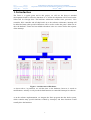
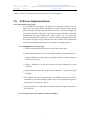
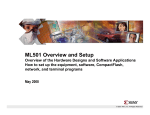
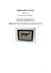
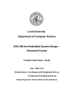
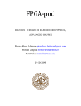
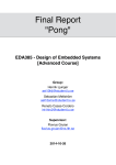
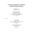
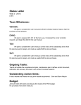
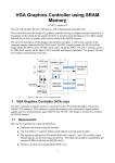
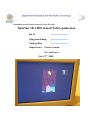
Embedded System Design Advanced Course EDA385
Spartan 3E-1200 -based Tetris game-box
Jia Li
[email protected]
Qingyuan Zhang
[email protected]
Yiming Huo
[email protected]
Supervisors: Flavius Gruian
Per Andersson
Oct, 19th, 2008
Jia Li
sx07jl7
Qingyuan Zhang sx07qz4
Yiming Huo
sx07yh4
Embedded System Design Advanced Course EDA385
Department of Electrical and Information Technology, LUND UNIVERSITY
Oct, 19th, 2008
Abstract
As in our design, we have developed Spartan 3E-1200 -based Tetris game-box on the Nexys-2
standard developments board under the Xilinx ISE 10.1 Design Suite. The user (player)can
operate the games on the standard keyboard by changing the direction and speeds of the tetris
shapes. The highlights of this design are we have saved 99.5% of BRAMS than the normal
design and the IP core has been designed to be more flexible and compatible to integrate more
other software-based games. The project is initiated by Department of Computer Science,
Lund University.
1
Contents
1 Introduction ................................................................................................................................3
2 Project Design..............................................................................................................................4
2.a Hardware Implementation…………………………………………….........................................4
2.b Software Implementation ………………………………………………………………….…….7
2.c Debugging and Optimizations in System Level……………..………………………………......12
2.d Brief Installations and User Manual………………………………………………………...…..13
3 Conclusions…………………………………………………………………………….….…....14
3.a Problems Encountered and Solved………………………………………………………………14
3.b Lessons Learnt and Future Work……………………………………………………………......14
3.c Contributions………………………………………………………………………………….....15
3.d Extras………………………………………………………………………………………........15
4 Acknowledgment............................................................................................................................15
5 Reference…………………………………………………………………………………….........15
2
Jia Li
sx07jl7
Qingyuan Zhang sx07qz4
Yiming Huo
sx07yh4
Embedded System Design Advanced Course EDA385
Department of Electrical and Information Technology, LUND UNIVERSITY
Oct, 19th, 2008
1. Introduction
The Tetris is a typical game and in this project, we will use the Nexys-2 standard
developments board to realize the functions of it. All the developments will be based on the
Xilinx ISE 10.1 Design Suite. The hardware architecture contains timer, processor, VGA
controller, PS/2 controller and off-chip RAM. As to the software architecture, interrupt will
be added and many other specified functions will be used to realize the game’s behaviors or
drive the hardware. Timer has been added to hardware since we want to realize the response
of the interrupt.
Figure 1.1 Architecture of Hardware
As shown above, in particular, we add the timer to the hardware, however, it needs no
modifications. Actually we only use the default functions to control the interrupts in software.
As to the software implementation, we integrate the Tetris programs into the whole system,
which contains many special functions recalled by interrupts, and these functions would
actually drive the hardware.
3
2. Project Design
2.a
Hardware Implementation
In the hardware implementation, the most critical design of VGA controller is to allocate the
resource of BRAM, since the size of BRAM is limited. As to this case, in the Tetris game, all
the shapes of Tetris diamonds are orthogonal and actually consist of many same little regular
squares, so we can just divide the 640*480 resolution by small 16*16 displaying blocks, in
which the same color will be drawn. We don’t need to specially define and store each pixel’s
color information into the BRAM, we just need to define every 16*16 matrix –based square,
which saves 99.5% of BRAM than the original solution.
Figure 2.1 BRAM Using Strategy
VGA controller
In the VGA controller part, as shown in fig2.1, we divide the whole screen into 40*30 units,
and each unit consists of 16*16 pixels. So in the memory part, each memory unit will store
the color information for each unit. And then by controlling the reading address, we can
extend this to the 640*480 resolution by repeatedly read the same unit for 16*16 times.
Through using this method we don’t need to store each pixel into the memory unit. Which
will save the memory size to a large extent, finally we only use 40*30 memory units to store
the whole 640*480 pixels’ color information.
So later in the software design, what we need to do is to change the relative units’ information
so as to change the whole screen’s displaying. And for the grid part, it is a spec ial case, we
solve this problem by using a MUX in the VGA controller, which means when we arrive at
the address where we need to draw a grid, we just choose another memory block which stores
only the grid color information instead of reading the data from the main memory block
which is used to store the Tetris blocks’ color data.
4
Jia Li
sx07jl7
Qingyuan Zhang sx07qz4
Yiming Huo
sx07yh4
Embedded System Design Advanced Course EDA385
Department of Electrical and Information Technology, LUND UNIVERSITY
Oct, 19th, 2008
Further more, for the color information stored in the memory, we allocate 3 bits for using,
which means it can stand for 8 main different colors on the screen.
Considering the SRAM, since in our case we use the off-chip memory to store the software
program, so we need to add a SRAM controller into IP core which will establish the
connection between processor and off-chip memory.
Figure 2.2 RTL Schematic of VGA Controller
As we can see from the figure 2.2, the block hsync_gen and the vsync_gen are used to
generate the correct synchronized signal to CRT displayer. And the Block_ram is used to
store the color information of each tetris block. The grid_color_gen stores the grid color
information, and through the color_data_select block which is controlled by the hcnt and vcnt,
it can select whether read the color information from the block ram or from the
grid_color_gen block. After this selection. The output 8 bits data will further be splitted into 3
parts which contend different color information. And then forward them to the output ports :
VGA_red,VGA_green ,VGA_blue.
PS/2 controller
The basic operation principle of PS/2 controller is, when a key is pressed, the keyboard will
sent the scan code to the ps/2 controller, due to the series communication between Keyboard
and PS/2 controller.. So the ps/2 controller won’t take all of those scan code at one time.
Actually every 25ms the ps/2 controller will take one bit of the scan code and push it into the
shift register. From repeating of this operation, the shift register will be filled with the scan
code. And then the ps2 controller will sent the scan code which is stored in the shift register to
the PLB bus. So finally the Microblaze processor will take the scan code from the PLB bus.
5
As to the PS/2 controller design, base on the one provided on the website,we made some little
modification, one is change the bus type to PLB bus, so it can fits the new hardware platform.
The second is we have to change the counter number in the original ps2 controller to
synchronize the clock of keyboard with the clock of the system, By doing this the PS/2
controller can return the right scan codes to the system., in our case because our processor’s
clock frequency is 50MHZ, so we only need to decrease the number of the counter in the state
machine to the value 1250 to meet the time requirement.
Timer/Counter
Finally considering the timer/counter, it is used to generate an interrupt and then the processor
will respond to that interrupt, and call the interrupt service function, and finally by executing
the interrupt service program we can control the falling of each Tetris block.And the
timer/counter is also used to control the falling speed of each Tetris blocks.
Its functions can be configured to be added to the hardware when initiating XPS. Then, it’s
the work of the software to set and activate it, since the timer/counter is the only interrupt
source. Then it isn’t necessary to implement an interrupt controller. And hereby in our design
what we do is to directly connect the interrupt output of the timer/counter to the interrupt
input of the processor.
Interrupt Control
In the overall system design, since the Microblaze only needs to handle one interrupt source
which is generated by the timer, so there is no reason to implement any other interrupt
controller module in to our hardware design. If we need to handle more than one interrupt, we
have to implement interrupt controller to response different interrupts and then send the
highest-priority interrupt to the Microblaze.
Finally we can get the Device Utilization as following:Selected Device : 3s1200efg320-5
Percentage
Name
Number Used(out of ) Total
Occupied
Slices:
2533
8672
29%
Slice Flip Flops
2971
17344
17%
Input LUTs
3761
17344
21%
bonded IOBs
65
250
26%
BRAMs
10
28
35%
MULT18X18SIOs
4
28
14%
GCLKs
4
24
16%
DCMs
1
8
12.5%
Number used as logic:
Number used as Shift registers
Number used as RAMs
Number of IOs
IOB Flip Flops
3308
197
256
65
64
6
Jia Li
sx07jl7
Qingyuan Zhang sx07qz4
Yiming Huo
sx07yh4
Embedded System Design Advanced Course EDA385
Department of Electrical and Information Technology, LUND UNIVERSITY
Oct, 19th, 2008
As shown above, the only 35% of BRAMs have been used, which means the optimization of
memory resource works and more extensive functions can be integrated.
2.b
Software Implementation
2.b.1. Introduction of the game
As the traditional Tetris game, two windows are displayed on the screen. The
larger one is the main window including one moving diamond (Tetris block)
and several static diamonds and the smaller window is just used to display the
next random diamond. The player can control moving diamonds by using the
four direction arrow keys, namely, ‘left’, ‘right’, ‘down’, ‘up’ to go left, right,
fall down and transform respectively. Each time when the diamond falls down,
the program will judge if any horizontal row can be deleted. The diamond will
fall down automatically and the player cannot stop it during the process.
2.b.2. Highlights of our Tetris game
a. Using off-chip RAM on the board to save the data for the game
b. Each diamond consists of four 16*16 displaying blocks as mentioned in 2.a
c. Setting boundaries of four edges of the play window so that the diamond
will not move out of it.
d. Using a structure to record the position and color information of each
diamond.
e. Drawing different colors and shapes for the diamonds
and blue).
(red, yellow, green
f. The diamond falls down spontaneously. The default moving speed can be
controlled by the timer interrupt, and the player can accelerate the speed by
pressing the direction arrow ‘down’.
e. The game will be over when the new diamond reaches the upper boundary of
the game area.
2.b.3. The flow chart of the software is shown in Figure:
7
Figure 2.3 Topology of Software Design
8
Jia Li
sx07jl7
Qingyuan Zhang sx07qz4
Yiming Huo
sx07yh4
Embedded System Design Advanced Course EDA385
Department of Electrical and Information Technology, LUND UNIVERSITY
Oct, 19th, 2008
a. When the game starts, the initialization of the whole system, such as setting the
boundaries, resetting the initial parameters of each Tetris block, will be done
in this step.
b. A new diamond will be obtained by calling the function get_diamond().
c. Enabling the interrupt and waiting for the response to the keyboard.
d. Response to the keyboard and doing the corresponding action such as moving
the diamond to left or right, transforming the shape of the moving diamond,
accelerating the falling speed and deleting the lines full of diamonds. If the
action is done and the game is not over, then continue to get a new diamond.
e. When the new diamond meets the up boundary of the display window, the
game is over.
f. Interrupt has to be stopped as soon as the game is over and another judgment
comes out. If F1 button of the keyboard is pressed, the game will start again;
otherwise, the game will stay at the current displaying.
2.b.4. Some detailed descriptions of the critical parts in software
2.b.4.1 Initialization
Boundary setting: in our design, we have three states for each block of the
display window. They are: no diamond, having movable diamond, having
static diamond. These three states are represented by three values 0, 1 and
2 respectively. The method to set the boundary is based on this very
assumption. The array of the main display window is 12*20. The value of
the blocks in row 0, row19, volume 0 and volume 11 are set to 1, which
means that we assume that there are already diamonds in these positions
and these blocks cannot be replaced by other diamonds. Meanwhile,
other blocks are set to zero to be ready to accept new diamonds.
2.b.4.2 Moving, transforming and deleting the diamonds
a. Moving: As we mentioned above, the player can control the movement
by using the direction arrows on the keyboard. For example, if the
expected moving direction is ‘left’ and assume that the current positions
of the four blocks consist of the diamond are (x1, y1), (x2,y2), (x3,y3),
(x4,y4), the moving steps are as follows: Firstly, judge the four values of
the blocks of the next position the diamond is about to move to. They are
(x1, y1-1), (x2, y2-1), (x3, y3-1), (x4, y4-1). A counter is needed to be
used here. If all the values of these four blocks are not 1, then we draw
the diamond color , change the values to 2 in the next position and draw
the background color, change the values to 0 in the current position.
Otherwise, the diamond will stay at the current position and the values of
9
the four diamond blocks are changed from 2 to 1.
b. Transforming: If the response to the keyboard is ‘up’, the diamond will
operate the transform function. Each diamond has a fixed generating
function such as creat_T(), create_L() and etc. In these functions, we have
defined all shapes of one certain diamond and put them in a chain list.
When we want to transform one diamond, the function show_next() will
be called. In the show_next() function, the information of the diamond to
be transformed will be got in the ‘create’ function, and the usual judging
methods will be applied again to check if current diamond can be
transformed.
c. Deleting: As mentioned before, show_down() function can not only
accelerate the falling speed of certain diamond, but also can delete the
rows full of diamonds. Each time the system will detect these rows from
bottom (row 19) to see if the value of the blocks in this row are all equal to
1, if it is true, the information of the line above will be written in this
line(color and value), which seems that one line has been deleted.
2.b.4.3 Interrupt
For the timer/counter in the software level, we start the timer at the
beginning of booting the system. After a fixed period which is set by us to
decide the falling speed of the Tetris blocks, the timer/counter will send an
interrupt signal, and the processor will respond to it by calling showdown()
function, so that the Tetris blocks will automatically fall down at fixed
distance per fixed time slot.
2.b.4.4 VGA displaying
In the software part, since we have already implemented the VGA controller
as an IP core into our hardware system, so then what to do next is only to
send the correct address, and corresponding data into the VGA controller.
Thereby the VGA controller could be imagined as a “painter” who will
finish the rest of work. In the software design, this process is realized by
using the function called gridpainter().
2.b.4.5 PS/2 controller
For the PS/2 control part, the software will receive the scan codes which are
sent by PS/2 controller and then it will call the corresponding code sections
to perform the movements of the Tetris blocks.
The following table lists some import functions we use during the software development
10
Jia Li
sx07jl7
Qingyuan Zhang sx07qz4
Yiming Huo
sx07yh4
Embedded System Design Advanced Course EDA385
Department of Electrical and Information Technology, LUND UNIVERSITY
Oct, 19th, 2008
Important special functions:
Function name
Initialize()
Functions
set the boundary of the grid;
initialize the values and colors for each grid
Return a random integer value
Get the values and colors for the current grids
and next grids of the moving diamond
Deleting the rows which are full of diamonds
Change the direction of diamonds
Accelerating the speed of falling
Move left
Move right
random()
gridpainter()
Scandel()
Show_next()
Show_down()
Show_left()
Show_right()
Software size
Text (bits)
21390
Data (bits)
1928
Bss (bits)
11818
11
Dec (bits)
35136
Hex (bits)
8940
2.c Debugging and Optimizations in System Level
Finally, we enter the stage of testing, debugging and verifications. After booting the system,
By testing many times, accidently, but ‘luckily’, we encountered the problems as following:
Figure 2.4 Problems of Boundaries
As shown in the figure 2.4, the Testris blocks sometimes could be moved out of the
boundaries of the game area, it happened when we moved the Tetris blocks to left or right
boundaries of grids while they were falling.
So we go back to the design topology again, check our most suspectable part which has
caused this problem--the special functions in the software, at last, the causes were found lying
on using the functions show_left() and show_right() without programming the commands of
limiting them insides the grids. Then, after debugging the errors, we finally got the right result
as below:
Figure2.5 The Right Displaying of Tetris Game
12
Jia Li
sx07jl7
Qingyuan Zhang sx07qz4
Yiming Huo
sx07yh4
Embedded System Design Advanced Course EDA385
Department of Electrical and Information Technology, LUND UNIVERSITY
Oct, 19th, 2008
2.d Brief Installations and User Manual of the Video
Game
Installations:
1. Open your host, connect the JTAG to the Nexys-2 standard developments board, connect
the USB wire to the host from the board;
2. Connect CRT displayer with VGA port and PS/2-based keyboard to the board;
3. Download the packed files of the project from the website:
4. Start Xilinx EDK 10.1 on your host, open the project file and download it to the FPGA;
5.Open the debug of the Xilinx EDK10.1, in the debug window, type the commands below:
dow executable.elf
run
After installing the game properly, following the operations below:
User manual:
1. Press the ‘ENTER’ key to start the game;
2. Move the Tetris blocks left and right by pressing ‘A’ or ‘D’ on the keyboard;
3. Move the diamonds faster by pressing ‘S’ if you want;
4. Transform the diamonds by pressing ’W’ on the keyboard;
5. Try to delete the rows of diamonds by putting them full in a row or more rows;
6. Press F1 to restart the game if your game is over.
Transform
Move left
Speed falling
Move right
Figure 2.6 Control keys of Tetris Game
13
3 Conclusions
3.a Problems Encountered and Solved
As to the Xilinx EDK 10.1, it will not support the OPB any more. So principles and protocols
of the PLB specification have to be researched and utilized since most examples of the VGA
controller on the website are based on OPB. And what’s more, a lot of reference about how to
interface the PLB with the other peripherals has been researched, particularly, the using of the
control signals of PLB.
Apart the problem above, another tricky problem appeared in the testing stage, that is, the
problem of the boundaries which have been mentioned in the debugging part. They have been
resolved by modifying the corresponding functions in the software.
3.b Lessons Learnt and Future Work
First of all, the technology flies so fast beyond people’s imaginations, Embedded System do
have changed human being’s lives in many ways. Obviously, it has quite a bright future.
Secondly, through this lecture, we gradually have a deeper understanding of this field and
‘what to do’ and ‘how to do’. As to a feasible project: practical title, schedule, allocation of
assignments, team spirit have to be planned and strictly stick to, every member should play
their most capable and appropriate roles in a project then the project can be finished
successfully in time. To sum up, affairs that are done by due degrees are soon ended.
On the aspects of academic learning, we gradually have a deeper understanding about the
top-down design methodology. Particularly in our process, when problems happened or the
results were not what we have imagined, we need to quickly go back to the topology, analyze
to locate where the errors were produced from, whether they were caused in SW level or HW
level, and how. One more point, the comprehensive thinking of whole system is critical in
designing a robust system, since many factors and elements have to be taken into
considerations synchronously in the HW/SW co-design.
And besides the above, it always works like ‘no pains, no gains’. It’s extremely hard when the
problems appeared and got people stuck for hours or even days, man can become quite upset
to lose the patience, however, what we need to do is just hold on, never give up. It’s better for
one to review the design methodologies, and then ask for some clues or suggestions from
experienced people. It normally can save much time and resolve problems quickly. Then, the
turning point is close to you.
Finally, due to the lack of project experience, we didn’t find enough time for the optimizations
of the project, for example, we thought we could add the scores board and some beautiful
picture as the background. We also expect to generate some music by integrating the audio
functions.
14
Jia Li
sx07jl7
Qingyuan Zhang sx07qz4
Yiming Huo
sx07yh4
Embedded System Design Advanced Course EDA385
Department of Electrical and Information Technology, LUND UNIVERSITY
Oct, 19th, 2008
3.c Contributions
Name
Jia Li
Jobs Assigned
Hardware design, namely, VGA controller, PS/2
Controller modifications;
Guidance on software design especially in
Interrupt;
Technical manager;
Qingyuan Zhang
Software design;
Hardware assistant design in Timer;
Coordinator and secretary;
Yiming Huo
Software assistant design in Tetris game C
programming;
Debugging and testing;
Proposal, Presentation and Report ;
Documents organizations and editing.
Of which, in the report part, Jia Li is in charge of hardware part, Qingyuan Zhang works on
summarizing the main ideas of the software part, Yiming Huo takes responsibilities for the
debugging part, user manual part, and overall report organization, arranging, editing and
rectifications.
3.d Extras
From our on line resources, the relative screen shots, diagrams, schematics, address the
project can be downloaded from the link as below:
http://www.edacn.net/bbs/viewthread.php?tid=133153&page=1&extra=page%3D1#pid11635
20
4
Acknowledgement
We should firstly give our great thanks to Flavius Gruian, Per Andersson, who have given us
careful guidance and helps during the project and also the previous laboratories of the
Embedded System courses.
And we also remember our best regards to our classmates who work with and help us together
during this period. Tack så mycket !
5
Reference
[1] Digilent, inc - Nexys2 board Reference Manual, 2008
[2] Xilinx, Inc – Xilinx ISE 10.1 Design Suite Software Manuals and Helps-PDF collection,
2008
[3] W. Wolf, ”Computers as Components: Principles of Embedded Computing Systems
Design”, Morgan Kaufman Publisher, 2001
[4] http://www.cs.lth.se/EDA385/
15