1
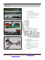
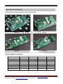
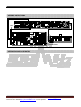
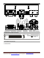
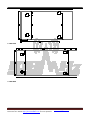
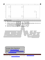
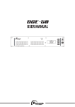
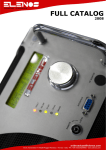
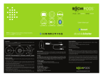
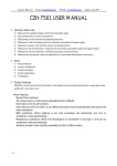
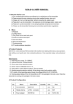
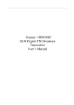
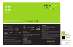
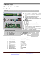
FMT Series
FM Broadcast Transmitter KIT
User Manual
FEATURES
The Kit includes an amplifier board, a control
panel board, an interface board and connection
cables.
Power adjustable: 0-30/50/80/150/300 watts
LCD displays working frequency, volume,
temperature, forward power, reflected power and
SWR,
Single knob operation.
Automatic power control maintaining the output
at any preset level
Pre-emphasis optional at 0, 50us or 75us.
Provided with SWR protection function and
temperature protection, raise alarm prompts once
meet any trouble while working.
Aluminum heat conduction component (A larger
heat sink is required when operating).
TECHNICAL SPECIFICATIONS
Power step:
Frequency Range:
Frequency step:
Modulation mode:
Tuning Design:
Frequency deviation:
Harmonic:
Frequency Stability:
Parasitic amplitude
Frequency Response:
SNR:
Transmission Signal:
Audio Input Level:
Audio Input Connect:
Stereo Separation:
RF Output Impedance:
1 watt (30W, step 0.1 watt)
87.5MHz to 108MHz
100 KHz
WFM
Stable PLL Technology
< ±75KHz
More than 65dB
± 10 PPm (-10 ° C to +60 ° C )
Less than 0.2%
50 - 15000Hz
More than 50dB
FM Stereo or Mono
-15db Max: -30db
RCA
More than 40dB
50 Ohm
Revised by BG7CR on Nov-1st 2012. Any question please send email to [email protected]
Please visit our website http://www.108MHz.com for more products.
COMPONENTS
1. Control panel board
It includes FM modulation circuit,
user interface circuit, RF drive
circuit, fan control circuit, auto
power control circuit.
The RF output of this board is 1
watt.
---------------------------------------------------------------------------------------------------------------------------------
2. Interface Board
Dual stereo audio input interface.
RS232 port (for Program debug,
optional).
AUX interface.
Signal
input
level
preset
potentiometer.
---------------------------------------------------------------------------------------------------------------------------------
3. Connection cables
Connect control board with amplifier
board cable.
Connect control board with interface
board cable.
RF cable: connect control board with
the final stage amplifying board.
Fool-proofing designed by color with
IDC interface.
---------------------------------------------------------------------------------------------------------------------------------
Revised by BG7CR on Nov-1st 2012. Any question please send email to [email protected]
Please visit our website http://www.108MHz.com for more products.
FMT SERIES AMPLIFIER BOARD
Amplifier board vary depending what you buy. Below are the details.
FMT-30A
FMT-50A
FMT-150A
FMT-300A
------------------------------------------------------------------------------------------------------------------------------------AMPLIFY BOARD SPECIFICATIONS
------------------------------------------------------------------------------------------------------------------------------------FMT-30A
FMT-50A
FMT-150A
FMT-300A
1W
1W
1W
1W
0-30W
0-50W
0-150W
0-300W
DC 28V
DC 48V
DC 45V
Input power level
Output power level
Operating voltage
DC
28V
Max current
3A
5A
6.6A
12A
Power tube
BLF245
MRF173
SD2931
BLF278
Heat plate
70*120mm
70*120mm
70*160mm
70*180mm
√
√
√
√
Extended heat sink need
Revised by BG7CR on Nov-1st 2012. Any question please send email to [email protected]
Please visit our website http://www.108MHz.com for more products.
ASSEMBLY INSTRUCTIONS
DC IN
RF OUT
INTERFACE BOARD ILLUSTRATION
Revised by BG7CR on Nov-1st 2012. Any question please send email to [email protected]
Please visit our website http://www.108MHz.com for more products.
CONTROL PANEL BOARD ILLUSTRATION
HEAT CONDUCTIVE PLATE SIZE
1. FMT-30A/FMT-50A
Revised by BG7CR on Nov-1st 2012. Any question please send email to [email protected]
Please visit our website http://www.108MHz.com for more products.
2. FMT-150A
3. FMT-300A
Revised by BG7CR on Nov-1st 2012. Any question please send email to [email protected]
Please visit our website http://www.108MHz.com for more products.
IMPORTANT NOTES
A big heat sink is required when operating.
Cooling fan interfaces are provided on the control board and its operating voltage is 12V. You can use
1~2 cooling fan(s) according to your needs.
Fan current should be no more than 0.5A.
Please check our AN101 application note for more details.
Overseas Sales Department
Online Store: http://www.108MHz.com
eBay store: http://stores.ebay.com/Warner-RF-Center
E-Mail: [email protected] [email protected]
Revised by BG7CR on Nov-1st 2012. Any question please send email to [email protected]
Please visit our website http://www.108MHz.com for more products.