1
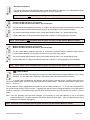
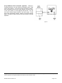
M INI -R EMOTE ™ U SER ’ S M ANUAL Rev 2.0 28-Sep-2015 Thank you for purchasing the Ashby Solutions Mini-Remote option for your Neo Instruments mini-Vent™ or mini-Vent for Organ™. (From this point, unless there are important differences, we’ll refer to them both as the ‘mini-Vent.’) The Mini-Remote allows the mini-Vent to be used with a variety of remote switches and onboard controls, and even to be controlled in ways that are not possible on a stock mini-Vent. The Mini-Remote is compatible with both mini-Vent models; however, some features can only be used on the organ model. Please see the Operating Modes section for details. INSTALLATION The Mini-Remote is not a ‘DIY’ product; it should be installed by an authorized Neo Instruments dealer or repairer. Once the Mini-Remote is installed, it replaces the Bypass switch on the mini-Remote with a 1/4" TRS phone jack for connection to remote control devices. The mini-Vent’s Speed switch is still active, and can still be used as a speed control. The Mini-Remote gets power from the mini-Vent, and requires no additional connections. OPERATING MODES The Mini-Remote has thirteen (13) operating modes, seven for halfmoon and th ‘legacy’ pedals, and the rest for momentary foot switches. It has a special 14 mode for programming. All modes are selected with the DIP switch found just below the words MINI-REMOTE™ on the board (Figure 1). Please read this next section to choose your operating mode. Your installer can set the switch to the proper position, or a pen or small screwdriver can be used to make any necessary changes. If you have any questions, please contact your installer or Ashby Solutions. Figure 1 It’s best to make switch changes while the mini-Vent is unplugged from its power adapter. (The Mini-Remote reads the DIP switch at each power-up, so the mini-Vent has to be turned off, anyway.) Also, be careful not to apply excessive force to the DIP switch while changing settings; failure to do so may damage the device. NEO REMOTE MODE (DEFAULT) This setting is compatible with the Neo Instruments Remote Footswitch made for the original Ventilator. It is also compatible with many other Ventilator peripherals: Hammond-Suzuki CU-1 Nord C1/C2 halfmoon VENT-11/11U adapters Trek II VIB-3 Ashby Solutions’ remote pedals and Halfmoons A 3-wire cable and TRS plug are required to connect the Mini-Remote to the switch. Wiring is the same as for the original Ventilator. Note: This mode was designed to be used with the mini-Vent for Organ as a full-time rotating speaker substitute, and there is no way to trigger Bypass to turn the effect on and off. The mini-Vent for Organ powers up with the Vent effect on, so everything works properly. The guitar mini-Vent, however, powers up in Bypass, and since this situation has no workaround, this mode cannot be used on the guitar version. Mini-Remote User’s Guide v2.0 Page 1 of 5 NEO REMOTE WITH DELAY This setting works just like Neo Remote Mode, except that it adds an additional 1 sec. delay between speed changes, to simulate the speed-switching lag seen on a classic Leslie 122. Note: This mode is not compatible with the guitar mini-Vent (see Neo Remote Mode for details). CLASSIC TWO-WAY HALFMOON (TOP SETTING) CLASSIC TWO-WAY HALFMOON WITH DELAY (BOTTOM SETTING) The first switch setting supports connection of a classic two-speed (Chorale-Tremolo) halfmoon switch with the closed contacts selecting Chorale speed, as seen in most vintage console Hammond setups. The second switch setting works the same, except that it adds the extra 1 sec. speed change delay. A 2-wire cable with a TS plug on the Mini-Remote side is required. The Ring position is not used. Note: These modes are not compatible with the guitar mini-Vent (see Neo Remote Mode for details). MODERN TWO-WAY HALFMOON (TOP SETTING) MODERN TWO-WAY HALFMOON WITH DELAY (BOTTOM SETTING) The first switch setting supports connection of a two-speed (Chorale-Tremolo) halfmoon switch with the closed contacts selecting Tremolo speed, as seen in many modern organ setups. The second switch setting works the same, except that it adds the extra 1 sec. speed change delay. A 2-wire cable with a TS plug on the Mini-Remote side is required. The Ring position is not used mode. Note: These modes are not compatible with the guitar mini-Vent (see Neo Remote Mode for details). ÜBER 122 MODE Like Neo Remote Mode, this setting uses a halfmoon switch that follows the Gigger Halfmoon / CU-1 wiring standard. A 3-wire cable with a TRS plug is required to connect the Mini-Remote to the switch. In ‘normal’ Uber 122 Mode use, the halfmoon acts as if it were a two-way switch: moving it all the way to the left selects Chorale speed; and all the way to the right selects Tremolo speed. The center position has no effect on the speed … or does it? The Off position is used to toggle between Chorale-Tremolo and Stop-Tremolo use – i.e., it connects and disconnects the ‘virtual Chorale motors’ of the mini-Vent. Triggering this change requires putting the halfmoon in the Off position for about 3 seconds. If the halfmoon was last used in the Chorale position, the mini-Vent will also switch to Tremolo speed. Note: Once the operating mode has been changed, it is necessary to move the halfmoon to one of the speed positions (Chorale or Tremolo) before the Off position becomes active again. (This is to prevent issues if the halfmoon is accidentally unplugged.) Note: This mode is not compatible with the guitar mini-Vent (see Neo Remote Mode for details). Mini-Remote User’s Guide v 2.0 Page 2 of 5 PASS-THRU CONNECTION (TOP SETTING) SWAPPED PASS-THRU CONNECTION (BOTTOM SETTING) The first switch setting provides foot switches that function exactly like the ones on a stock mini-Vent – except that they can be placed in a remote location. A 3-switch pedal can be used to provide dedicated switches for each function (Speed, Stop, Bypass). Tip: Ring: Tip+Ring: Toggles the Speed between Chorale (slow) and Tremolo (fast) Toggles between Bypass and Effect settings Selects Stop speed The second switch setting swaps the Ring and Tip+Ring functions, making it easier to select Stop with a 2-position pedal, and moving Bypass to the more complicated two-switch press. Tip: Ring: Tip+Ring: Toggles the Speed between Chorale and Tremolo Selects Stop speed Toggles between Bypass and Effect settings A 3-wire cable with a TRS plug is required to connect to the Mini-Remote, wired as in Figure 2. The Mini-Remote senses the polarity of the switches (normally-open or normally-closed); however, polarity types cannot be mixed. If no switch is plugged in at startup, the Mini-Remote will assume normally-open polarity. There is no industry standard for which switch (left or right) is connected to the Tip or Ring on commercial foot switch pedals. This manual refers to the ‘Tip switch, ‘Ring switch,’ etc.; the physical locations may change between models and manufacturers. Figure 2 NEW 760 MODE This setting provides three functions – Speed, Stop, Bypass – from a 2-switch pedal, using an alternate method that eliminates the need to press two switches at once. The Stop and Bypass functions are controlled by the same switch, depending on how long itl was pressed; otherwise, operation is the same as Pass-Thru Connection (and the standard mini-Vent). Press Tip: Press Ring: Hold Ring for 2 sec.: Toggles the Speed between Chorale and Tremolo Selects Stop speed Toggles between Bypass and Effect settings A 3-wire cable with a TRS plug is required to connect to the Mini-Remote, as shown in Figure 2. (S3 is not used.) As in Pass-Thru Connection, the polarity of the switches is auto-sensed at startup. NEW 122 MODE This setting provides three functions – Speed, Stop, Bypass – from a 2-switch pedal, but with functions more closely aligned with the ‘122 Style’ setting in the Neo Remote Footswitch and many Ashby Solutions pedals: Press Tip switch: Hold Tip for 2 sec. Press Ring: Toggles the Speed between ‘Slow speed’ and Tremolo Toggles between Tremolo-Chorale and Tremolo-Stop operation Toggles between Bypass and Effect settings Please note that the mini-Vent will change speeds to confirm that the Brake operation has been changed: if in Chorale or Stop it will change to Tremolo and vice versa. A 3-wire cable with a TRS plug is required to connect to the Mini-Remote, as shown in Figure 2. (S3 is not used.) As in Pass-Thru Connection, the polarity of the switches is auto-sensed at startup. Mini-Remote User’s Guide v2.0 Page 3 of 5 SINGLE SWITCH MODE This mode allows control of the mini-Vent with one remote pedal/switch (ex: a sustain pedal): Short press: 2 sec. Press: Toggles the Speed between Chorale and Tremolo Toggles between Bypass and Effect settings A 2-wire cable with a TS plug is required to connect the Mini-Remote to a 1-switch pedal with momentary contacts. The Ring position is not used. As in Pass-Thru Connection, the polarity of the switch is auto-sensed at startup. SINGLE 122 MODE This mode works similar to Single Switch Mode, except that a long press changes the Brake setting. Basic functionality is the same as described in New 122 Mode. There is no ability to select Bypass: Short press: Toggles the Speed between Chorale (or Stop) and Tremolo 2 sec. Press: Toggles between Tremolo-Chorale and Tremolo-Stop operation Please note that the mini-Vent will change speeds to confirm that the Brake operation has been changed: if in Chorale or Stop it will change to Tremolo and vice versa. A 2-wire cable with a TS plug is required to connect the Mini-Remote to a 1-switch pedal with momentary contacts. The Ring position is not used. As in Pass-Thru Connection, the polarity of the switch is auto-sensed at startup. Note: This mode is not compatible with the guitar mini-Vent (see Neo Remote Mode for details). PROGRAMMING MODE This mode converts a single switch (or the Tip connection of a 2-switch pedal) into the Bypass signal. Short press: 2 sec. Press: Sends a Bypass switch pulse Sends a Save Data pulse and exits Preset Programming mode on the mini-Vent A 2-wire cable with TS plug is required to connect the Mini-Remote to the switch; normally, a momentary pedal. The Ring position is not used. As in Pass-Thru Connection, the polarity of the switch is auto-sensed at startup. Most pedals will need this function to program the mini-Vent. Please see the next section for more details. A/B PRESET PROGRAMMING Programming presets with the Mini-Remote uses the same basic steps: press and hold the mini-Vent’s Slow/Fast switch for 3 sec. or so while powering on. Once the mini-Vent is in its Preset Programming mode, use the Bypass and Slow/Fast switches as Down/Dec. and Up/Inc. selectors, respectively. Then, a ‘long’ press will save the settings in the presets. Since there is no Bypass switch with the Mini-Remote, though, a remote switch will need to substitute in some of the steps. Depending on the control setup, there are the several ways to program the presets: Universal Method – Change to Programming Mode; use a single momentary switch – or the Tip switch of a dual footswitch – as Bypass. Use the mini-Vent’s onboard Speed switch for the other signal, as shown in Figure 3. At the end of the programming session, hold the foot switch down for 2 sec. to store the settings and return to normal operation. Neo Remote Mode (optional) – Change to Programming Mode. Put the halfmoon or other control in the Stop/Off position before powering on the mini-Vent. Move the halfmoon, etc. into the Chorale position, and then return to Stop/Off, to simulate pressing Bypass. (Two presses/movements are required to send one pulse.) Use the miniVent’s onboard Speed switch for the other signal. At the end of the programming session, switch to the closed position again, and leave it there until the mini-Vent returns to normal operation. Mini-Remote User’s Guide v2.0 Page 4 of 5 2-way Halfmoon direct connection (optional) – Change to Programming Mode; use the halfmoon as Bypass switch: start in the ‘open’ position – you’ll need to figure out which is which – then momentarily move to the ‘closed’ position, and then return to the open position, for each Bypass switch press. Use the mini-Vent’s onboard Speed switch for the other signal. At the end of the programming session, switch to the closed position again, and leave it there until the mini-Vent returns to normal operation. Figure 3 Copyright © 2014-2015 by Bruce A. Wahler for Ashby Solutions. Ashby Solutions and the Ashby Solutions logo are trademarks of Ashby Solutions. All other trademarks and registered trademarks are property of their respective owners. Mini-Remote User’s Guide v2.0 Page 5 of 5