1
Gas Operations and Maintenance Procedures
Rev: 01 Jun 2008
Unitil
Gas Operations and Maintenance Procedures
Gas Operations and Maintenance Procedures
Rev: 01 Jun 2008
Table of Contents
Chapter 1 - General....................................................................................................................................... 1
1.01.00 GENERAL CODE REQUIREMENTS ....................................................................................... 1
1.02.01 MASSACHUSETTS GAS DISTRIBUTION CODE: 220CMR 100.00 ..................................... 1
1.03.01.1 Massachusetts Department of Telecommunications and Energy (DTE) .............................. 2
1.03.01.2 Department of Transportation (DOT) ................................................................................... 4
1.03.02 ANNUAL REPORTS .................................................................................................................. 5
1.04.00 GENERAL PROCEDURES FOR THE DISTRIBUTION DEPARTMENT.............................. 5
1.05.00 JOB PREPARATION .................................................................................................................. 5
1.06.00 JOB PLANNING ......................................................................................................................... 6
1.07.00 YARD PROCEDURES ............................................................................................................... 6
1.08.00 POST JOB PROCEDURES......................................................................................................... 6
1.09.00 REPORTING SAFETY-RELATED CONDITIONS .................................................................. 7
1.10.00 SAFETY-RELATED CONDITION REPORT............................................................................ 9
1.11.00 EMERGENCY REPAIR OF MAINS AND SERVICES .......................................................... 12
1.12.00 REGULATOR OR METER STATIONS, VAULTS, PITS OR CABINETS - GENERAL ..... 12
1.12.01 LOCATION ........................................................................................................................... 12
1.12.02 DESIGN ................................................................................................................................. 12
1.12.03 VENTING.............................................................................................................................. 13
1.12.04 OVERPRESSURE PROTECTION ....................................................................................... 13
1.15.00 HIGH BTU PIPELINE NATURAL GAS (Air Stabilization) ................................................... 13
Chapter 2 - Maintenance............................................................................................................................. 14
2.01.00 WORK AREA PROTECTION.................................................................................................. 14
2.01.01 GENERAL: 49 CFR 192:605(b)............................................................................................ 14
2.01.02 PURPOSE:............................................................................................................................. 14
2.01.03 BASIC RULES: ..................................................................................................................... 15
2.02.00 WORK AREA PROTECTION EQUIPMENT.......................................................................... 16
2.03.00 WORK AREA PROTECTION PROCEDURES....................................................................... 16
2.03.02 USE TRUCK AS SHIELD: ................................................................................................... 17
2.03.03 BARRICADING WORK AREA:.......................................................................................... 17
2.03.04 NARROW STREET: ............................................................................................................. 17
2.03.05 EMPLOYEE SAFETY: ......................................................................................................... 17
2.03.06 SPOIL BANK AS SHIELD:.................................................................................................. 17
iii
Gas Operations and Maintenance Procedures
Rev: 01 Jun 2008
2.03.08 REARRANGE PROTECTION: ............................................................................................ 17
2.03.09 BARRICADE REMOVAL:................................................................................................... 18
2.03.10 NIGHT PROTECTION: ........................................................................................................ 18
2.03.11 STEEL PLATES:................................................................................................................... 18
2.03.12 MUNICIPAL ASSISTANCE: ............................................................................................... 18
2.03.13 REGULATIONS:................................................................................................................... 18
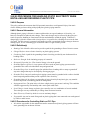
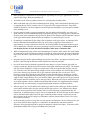
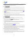
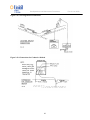
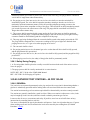
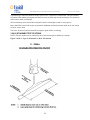
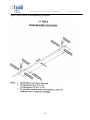
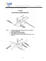
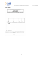
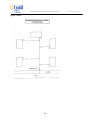
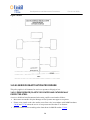
2.03.14 WORK AREA PROTECTION - DIAGRAMS ..................................................................... 19
2.04.00 PROTECTING UNDERGROUND FACILITIES..................................................................... 23
2.04.01 GENERAL 49 CFR 192:605 (b) (3) (4) ................................................................................ 23
2.05.00 DAMAGE PREVENTION PROGRAM ................................................................................... 24
2.05.01 DIG SAFE- 49 CFR 192.614................................................................................................. 24
2.06.00 GENERAL LOCATING AND MARKING PROCEDURES ................................................... 25
2.07.00 EXCAVATION PROCEDURE................................................................................................. 27
2.08.00 TRENCHING PROCEDURE.................................................................................................... 27
2.09.00 Inspection of Materials- 49 CFR 192.307.................................................................................. 29
2.10.00 FIELD INSPECTION OF PLASTIC PIPE ............................................................................... 29
2.11.00 DISTRIBUTION SYSTEM SURVEY ...................................................................................... 29
2.12.00 FLAME IONIZATION SURVEY............................................................................................. 30
2.13.00 PRE-PAVING SURVEY City and Town Paving Projects ........................................................ 30
2.14.00 WINTER PATROL SURVEY- 49 CFR 192.721 (a) (b)........................................................... 31
2.15.00 SERVICE LEAK AND CORROSION SURVEY..................................................................... 31
2.15.01 OUTSIDE METERS.............................................................................................................. 31
2.15.02 INSIDE METERS:................................................................................................................. 32
2.16.00 PUBLIC BUILDING INSPECTION- 220 CMR 101.06 (21) (a) (b) .................................... 32
2.17.00 INTERIOR GAS PIPING CORROSION AND LEAK SURVEY............................................ 33
2.17.01 PROCEDURE:....................................................................................................................... 33
2.17.02 EXCEPTIONS: ...................................................................................................................... 33
2.18.00 DISTRIBUTION VALVE INSPECTION ................................................................................. 33
2.19.00 Critical Valve Inspection ........................................................................................................... 36
2.20.00 REPORTED LEAKS ASSOCIATED WITH DAMAGE TO GAS LINES.............................. 36
2.21.00 LEAK CLASSIFICATION........................................................................................................ 36
2.21.01 CLASS I LEAKS:.................................................................................................................. 36
2.21.02 CLASS II LEAKS:................................................................................................................. 36
iv
Gas Operations and Maintenance Procedures
Rev: 01 Jun 2008
2.21.03 CLASS III LEAKS: ............................................................................................................... 37
2.22.00 LEAK DISPATCHING PRIORITY .......................................................................................... 37
2.23.00 FOREIGN ODOR COMPLAINTS ........................................................................................... 38
2.23.01 GENERAL:............................................................................................................................ 38
2.23.02 BUILDINGS (INSIDE): ........................................................................................................ 38
2.23.03 BUILDINGS (OUTSIDE): .................................................................................................... 38
2.24.00 RECORDS - LEAKS- 220 CMR 101.06................................................................................... 39
2.24.01 GENERAL:............................................................................................................................ 39
2.24.02 ITEMS TO REPORT:............................................................................................................ 39
2.25.00 PINPOINTING FOR LEAKS.................................................................................................... 39
2.26.00 REPAIR OF GAS LEAK ON DISTRIBUTION MAIN ........................................................... 40
2.27.00 UPRATING MAINS AND SERVICES TO HIGHER OPERATING PRESSURES ........... 41
2.27.01 PLANNING ........................................................................................................................... 41
2.27.02 PREPARATION: ................................................................................................................... 41
2.27.03 OPERATION: ........................................................................................................................ 42
2.28.00 CAST IRON AND BARE STEEL REPLACEMENT AND ABANDONMENT PROGRAM 43
2.28.01 THE PROGRAM ................................................................................................................... 45
2.29.00 CORROSION CONTROL MONITORING AND RECORD KEEPING -CFR 192.453 ......... 47
2.29.01 MONITORING:- CFR 192.465............................................................................................. 47
2.29.02 REPAIRS:- CFR 192.485 ...................................................................................................... 47
2.29.03 RECORD KEEPING: - CFR 192.491 ................................................................................... 48
2.30.00 ATMOSPHERIC CORROSION - CFR 192.481 ...................................................................... 48
2.31.00 PRECAUTIONS FOR UNSAFE GAS ACCUMULATION IN TRENCHES.......................... 48
2.31.01 Purpose................................................................................................................................... 49
2.31.02 General Information............................................................................................................... 49
2.31.03 Definition(s) ........................................................................................................................... 49
2.31.04 Identifying Hazardous Outside Atmospheres ........................................................................ 49
2.31.05 PPE Requirements.................................................................................................................. 50
2.31.06 Minimum 20’ Safety Perimeter.............................................................................................. 50
2.31.07 Make Safe Response .............................................................................................................. 50
2.31.08 Working Within a Hazardous Atmosphere ............................................................................ 51
2.31.09 Storage, Availability and Care of F.R. P.P.E ......................................................................... 51
2.32.00 PROCEDURE FOR INVESTIGATION OF FAILURES- CFR 192.2515 ............................... 52
v
Gas Operations and Maintenance Procedures
Rev: 01 Jun 2008
2.32.01 DEFINITION: ........................................................................................................................ 52
2.32.02 OBJECTIVE: ......................................................................................................................... 52
2.32.03 PROCEDURE:....................................................................................................................... 52
2.33.00 CONFINED SPACE ENTRY.................................................................................................... 52
2.33.01 PREPARATION: ................................................................................................................... 53
2.33.02 PROCEDURE:....................................................................................................................... 53
2.34.00 REGULATOR PERFORMANCE TEST - ANNUAL- CFR 192. ............................................ 53
2.35.00 INTERNAL INSPECTION OF REGULATORS AT GATE STATIONS................................ 54
2.36.00 INTERNAL REGULATOR INSPECTION (REGULATOR STATIONS) .............................. 55
2.37.00 RELIEF VALVE INSPECTION AND TESTING - ANNUAL................................................ 56
2.38.00 INSTALLATION OF FITTINGS AND TAPPING A METALLIC MAIN.............................. 57
2.38.01 SELF TAPPING TEE ON STEEL MAIN- CFR 192.367 ..................................................... 57
2.38.02 LINE STOPPER OR EXTENSION STOPPER FITTING ON STEEL MAIN..................... 57
2.38.03 LATERAL OR SERVICE TAPS OFF OF CAST IRON MAINS- CFR 192.369 ................ 58
2.39.00 QUALIFICATION OF PLASTIC PIPE INSTALLERS- CFR 192.805 ................................... 59
2.39.01 PURPOSE .............................................................................................................................. 59
2.39.02 TEST REQUIREMENTS FOR QUALIFICATION ............................................................. 59
2.39.03 PLASTIC FUSION INCLUDING ELECTROFUSION: ...................................................... 60
2.39.04 TESTING OF FUSION JOINTS FOR QUALIFICATIONS ................................................ 60
2.39.05 MECHANICAL FITTINGS FOR PLASTIC PIPE: .............................................................. 60
2.39.06 EMPTY - FOR FUTURE USE .............................................................................................. 61
2.39.07 EMPTY - FOR FUTURE USE .............................................................................................. 61
2.39.08 EMPTY - FOR FUTURE USE .............................................................................................. 61
2.39.09 EMPTY - FOR FUTURE USE .............................................................................................. 61
2.39.10 EMPTY – FOR FUTURE USE ............................................................................................. 61
2.39.11 FUSION JOINTS................................................................................................................... 61
2.39.12 MECHANICAL FITTINGS .................................................................................................. 61
2.39.13 EMPTY - FOR FUTURE USE .............................................................................................. 61
2.39.14 REQUALIFICATION ........................................................................................................... 61
2.40.00 CASINGS- CFR 192.323........................................................................................................... 61
2.40.01 CASING INSULATORS:...................................................................................................... 61
2.40.02 CASING END SEAL: ........................................................................................................... 62
2.40.03 ELECTRICAL TEST:............................................................................................................ 62
vi
Gas Operations and Maintenance Procedures
Rev: 01 Jun 2008
2.40.04 CASING PIPE: ...................................................................................................................... 62
2.40.05 REMEDIAL ACTION FOR SHORTED PIPE: .................................................................... 62
2.41.00 EMPTY - FOR FUTURE USE.................................................................................................. 62
2.42.00 PROCEDURE FOR HANDLING STATIC ELECTRICITY WHEN INSTALLING AND
REPAIRING PLASTIC PIPE................................................................................................................. 63
2.42.00 Purpose................................................................................................................................... 63
2.42.01 General Information............................................................................................................... 63
2.42.03 Definition(s) ........................................................................................................................... 63
2.42.03 Procedures for Controlling Static on P.E. Pipe ...................................................................... 63
2.43.00 PIPE LOCATOR ....................................................................................................................... 65
2.43.01 GENERAL:............................................................................................................................ 65
2.43.02 INSTRUCTIONS:.................................................................................................................. 65
2.44.00 PHONE-TYPE INSULATING JOINT TESTER ...................................................................... 69
2.45.00 PROCEDURE FOR INSTALLING MECHANICAL FITTINGS ............................................ 70
2.46.00 DETERMINING PIPELINE STRAIN FROM SOIL DISPLACEMENT*............................... 71
2.47.00 PIPE CONDITION REPORT .................................................................................................... 73
2.47.01 GENERAL:............................................................................................................................ 73
2.47.02 PIPE COATING INSPECTION: ........................................................................................... 73
2.47.03 PIPE INSPECTION: CFR 49 192.307................................................................................... 74
2.47.04 REPORTING: ........................................................................................................................ 74
2.47.05 PIPE REPAIRS: ..................................................................................................................... 74
2.47.06 BELL JOINT SEALING: ...................................................................................................... 74
2.48.00 ODORIZATION VERIFICATION PROCEDURE- CFR 49 192.625...................................... 74
2.49.00 WELDING PROCEDURES- CFR 49 192.225 ......................................................................... 75
2.50.0 OIL TANK DECOMMISSIONING PROCEDURE FOR CONVERSION BURNER
INSTALLATIONS ................................................................................................................................. 75
2.51.00 MERCURY - HAZARDOUS MATERIAL HANDLING ........................................................ 75
2.51.01 PROCEDURE:....................................................................................................................... 76
2.51.02 IN THE EVENT OF A MERCURY SPILL: ......................................................................... 76
2.52.00 - APPENDIX D - Fitchburg Gas and Electric Light Company - Unprotected Pipe Risk
Assessment Guideline............................................................................................................................. 76
D1. Purpose......................................................................................................................................... 76
D2. Scope............................................................................................................................................ 77
D3. Risk Assessment .......................................................................................................................... 77
vii
Gas Operations and Maintenance Procedures
Rev: 01 Jun 2008
D4. Repair or Replace Decision.......................................................................................................... 83
D5. Development of replacement schedule ........................................................................................ 84
D6. Conclusion ................................................................................................................................... 84
Chapter 3 - Construction............................................................................................................................. 85
3.01.00 WORK AREA PROTECTION.................................................................................................. 85
3.01.01 GENERAL- 49 CFR 192:605(b) ........................................................................................... 85
3.01.02 PURPOSE: ............................................................................................................................. 85
3.01.03 BASIC RULES: ..................................................................................................................... 85
3.02.00 WORK AREA PROTECTION EQUIPMENT.......................................................................... 87
3.03.00 WORK AREA PROTECTION PROCEDURES....................................................................... 87
3.03.01 EARLY WARNING: ............................................................................................................. 88
3.03.02 USE TRUCK AS SHIELD: ................................................................................................... 88
3.03.03 BARRICADING WORK AREA:.......................................................................................... 88
3.03.04 NARROW STREET: ............................................................................................................. 88
3.03.05 EMPLOYEE SAFETY: ......................................................................................................... 88
3.03.06 SPOIL BANK AS SHIELD:.................................................................................................. 88
3.03.07 MINIMIZE CONGESTION: ................................................................................................. 88
3.03.08 REARRANGE PROTECTION: ............................................................................................ 88
3.03.09 BARRICADE REMOVAL:................................................................................................... 88
3.03.10 NIGHT PROTECTION: ........................................................................................................ 89
3.03.11 STEEL PLATES:................................................................................................................... 89
3.03.12 MUNICIPAL ASSISTANCE: ............................................................................................... 89
3.03.13 REGULATIONS:................................................................................................................... 89
3.03.14 WORK AREA PROTECTION - DIAGRAMS ..................................................................... 90
3.04.00 JOINING OF PLASTIC PIPE ................................................................................................... 94
3.04.01 PROCEDURE FOR MAKING BUTT FUSION JOINTS..................................................... 95
3.04.02 BUTT FUSION PARAMETERS .......................................................................................... 95
3. 04.03 BUTT FUSION PROCEDURE ............................................................................................ 95
3. 04.05 HYDRAULIC PRESSURES FOR TYPICAL BUTT FUSION APPLICATIONS ............. 99
3. 04. 06 SADDLE FUSION .............................................................................................................. 99
3. 04.07 EMPTY - FOR FUTURE USE ........................................................................................... 108
3. 04.08 EMPTY - FOR FUTURE USE ........................................................................................... 108
3. 04.09 EMPTY - FOR FUTURE USE ........................................................................................... 108
viii
Gas Operations and Maintenance Procedures
Rev: 01 Jun 2008
3. 04.10 EMPTY - FOR FUTURE USE ........................................................................................... 108
3. 04.11 EMPTY - FOR FUTURE USE ........................................................................................... 108
3. 04.12 EMPTY - FOR FUTURE USE ........................................................................................... 108
3. 04.13 EMPTY - FOR FUTURE USE ........................................................................................... 108
3. 04.14 EMPTY - FOR FUTURE USE ........................................................................................... 108
3. 04.15 EMPTY - FOR FUTURE USE ........................................................................................... 108
3. 04.16 EMPTY - FOR FUTURE USE ........................................................................................... 108
3. 04.17 CENTRAL ELECTROFUSION PROCEDURES .............................................................. 108
3. 04.18 EMPTY - FOR FUTURE USE ........................................................................................... 110
3. 04.19 ELECTRICAL REQUIREMENTS AND COOLING TIMES ........................................... 110
3. 04.20 EMPTY - FOR FUTURE USE ........................................................................................... 110
3. 04.21 CENTRAL ELECTROFUSION SADDLE FITTING JOINING PROCEDURES ............ 111
3.04.22 EMPTY - FOR FUTURE USE ............................................................................................ 112
3.04.23 TAPPING THE MAIN ........................................................................................................ 112
3.05.00 PROCEDURE FOR INSTALLING COMPRESSION COUPLINGS .................................... 112
3.05.01 PROCEDURE FOR INSTALLING POSILOCK (TM) Basement Tees ............................. 112
3.05.02 INSTALLATION PROCEDURE - BASEMENT END OF SERVICE INSTALLED FIRST
.......................................................................................................................................................... 112
3.05.03 INSTALLATION PROCEDURE - STREET END OF SERVICE INSTALLED FIRST .. 113
3.05.04 PROCEDURE FOR INSTALLING MAXI-GRIP (TM) COUPLINGS ............................. 113
3.05.05 PROCEDURE FOR INSTALLING DRESSER® TYPE 711 FITTINGS .......................... 115
3.05.06 PERFECTION PERMASERT® MECHANICAL COUPLINGS ....................................... 116
3.05.07 PERFECTION PERMALOCK® TEE ................................................................................ 117
3.06.00 BLANK - FOR FUTURE USE................................................................................................ 118
3.07.00 EXCAVATION PROCEDURE............................................................................................... 118
3.08.00 TRENCHING PROCEDURE.............................................................................................. 118
3.08.01 TRENCH SHORING TABLE ............................................................................................. 119
3.09.00 PRECAUTIONS FOR UNSAFE GAS ACCUMULATION IN TRENCHES........................ 120
3.10.00 TRENCH PADDING AND BACKFILLING PROCEDURE FOR MAINS .......................... 120
3.10.01 GENERAL ........................................................................................................................... 120
3.10.02 PROCEDURE - (See Figure 3.10.02.1)............................................................................... 120
3.11.00 PIPE BEDDING AND FINAL BACKFILLING – MATERIAL STANDARDS ............... 122
3.12.00 INSTALLATION OF FITTINGS AND TAPPING A METALLIC MAIN - 49 CFR 192.151
.............................................................................................................................................................. 123
ix
Gas Operations and Maintenance Procedures
Rev: 01 Jun 2008
3.12.01 SELF TAPPING TEE ON STEEL MAIN........................................................................... 123
3.12.02 LINE STOPPER OR EXTENSION STOPPER FITTING ON STEEL MAIN - 49 CFR
192.627.............................................................................................................................................. 124
3.12.03 LATERAL OR SERVICE TAPS OFF OF CAST IRON MAINS - 49 CFR 192.367......... 124
3.13.00 PROCEDURE FOR HANDLING STATIC ELECTRICITY WHEN INSTALLING AND
REPAIRING PLASTIC ........................................................................................................................ 125
3.13.0 Purpose................................................................................................................................... 125
3.13.01 General Information............................................................................................................. 126
3.13.02 Definition(s) ......................................................................................................................... 126
3.13.02 Procedures for Controlling Static on P.E. Pipe .................................................................... 126
3.14.00 LOWERING MAINS AND SERVICES ................................................................................. 127
3.15.00 CUT-OUT AND TIE-IN PROCEDURES FOR MAINS ........................................................ 129
3.15.01 ESTABLISH AREA TO BE AFFECTED ON PLANS. ..................................................... 129
3.15.02 PREPARATION .................................................................................................................. 129
3.15.03 PERFORMANCE OF WORK............................................................................................. 130
3.15.04 CORROSION CONTROL - 49 CFR 192.467..................................................................... 130
3.15.05 COMPLETION.................................................................................................................... 130
3.16.00 STANDARD PIPE SPECIFICATIONS .................................................................................. 131
3.17.00 QUALIFICATION OF WELDERS......................................................................................... 132
3.18.00 REPLACING A DAMAGED SECTION OF PLASTIC PIPE................................................ 132
3.19.00 REPLACEMENT OF CAST IRON MAINS – 220 CFR 113.00 ............................................ 133
3.19.01 REPLACEMENT OF CAST IRON PIPE AT TRENCH CROSSINGS - 220 CFR 113.07134
3.19.02 LENGTH OF PIPE TO BE REPLACED WHEN CROSSED BY 3RD PARTY: ................ 134
3.19.03 OPTIONS WHEN CROSSED BY A 3RD PARTY:............................................................. 134
3.19.04 REPLACEMENT OF CAST IRON ADJACENT TO PARALLEL EXCAVATIONS ...... 135
3.19.05 DEFINITIONS..................................................................................................................... 135
3.19.06 REPLACE CAST IRON PIPE IN THE FOLLOWING THREE SITUATIONS:............... 136
3.19.07 LENGTH OF REPLACEMENT - PARALLEL TRENCHES ............................................ 137
3.20.00 INSTALLATION OF MAINS UNDER RAILROADS – 49 CFR 192.323............................ 138
3.20.01 RECOMMENDED CASING SIZES ................................................................................... 138
3.21.00 HIGHWAY CROSSINGS REQUIRING CASINGS FOR PIPE ............................................ 139
3.22.00 OPEN CUT ROAD CROSSINGS ........................................................................................... 140
3.23.00 PIGGING PROCEDURES FOR STEEL AND PLASTIC MAINS ........................................ 141
3.24.00 BORING PROCEDURE FOR MAINS & SERVICES ........................................................... 141
x
Gas Operations and Maintenance Procedures
Rev: 01 Jun 2008
3.24.01 DESCRIPTION OF WORK ................................................................................................ 142
3.24.02 CONSTRUCTION METHODS .......................................................................................... 142
3.25.00 INSERTING A MAIN WITH PLASTIC PIPE ....................................................................... 142
3.25.02 TYPICAL STARTING DITCH........................................................................................... 143
3.26.00 BRIDGE CROSSING PROCEDURE ..................................................................................... 144
3.27.00 SQUEEZE OFF PROCEDURE FOR PLASTIC PIPE............................................................ 145
3.28.00 PROCEDURE FOR PURGING MAINS – 49 CFR 192.629 .................................................. 146
3.28.01 SCOPE ................................................................................................................................. 147
3.28.02 GENERAL ........................................................................................................................... 148
3.28.03 MAINS THAT WILL BE PURGED WITH NATURAL GAS OR AIR ............................ 148
3.28.04 SERVICE LINES THAT WILL BE PURGED WITH NATURAL GAS OR AIR ............ 148
3.28.05 MAINS THAT WILL BE INERT GAS PURGED (SLUG METHOD) ............................. 148
3.28.06 SERVICE LINES THAT WILL BE INERT GAS PURGED (SLUG METHOD) ............. 148
3.28.07 MAIN PURGING REQUIREMENTS UNDER ANY METHOD ...................................... 149
3.28.08 SERVICE LINE PURGING REQUIREMENTS UNDER ANY METHOD ...................... 150
3.28.09 Performing The Purge.......................................................................................................... 150
3.28.10 Performing the Inert Gas Purge (Slug Method) ................................................................... 151
3.28.11 Safety During Purging ......................................................................................................... 152
3.29.00 CATHODIC TEST STATIONS – 49 CFR 192.469................................................................ 152
3.29.01 GENERAL:.......................................................................................................................... 152
3.29.02 STANDARD TEST STATIONS: ........................................................................................ 153
3.30.00 THERMITE BRAZING OF ELECTRICAL CONNECTIONS .............................................. 157
3.30.02 MATERIAL ......................................................................................................................... 158
3.30.03 PREPARATION OF STEEL AND CAST IRON SURFACES: ......................................... 158
3.30.04 WELDING PROCEDURE: ................................................................................................. 158
3.31.00 PRESSURE-TEST REQUIREMENTS FOR GAS MAINS – 49 CFR 192.507 ..................... 159
3.31.01 PRESSURE TESTING REQUIREMENTS ........................................................................ 159
3.32.00 LINE MARKERS FOR TRANSMISSION LINES AND DISTRIBUTION MAINS ............ 161
3.32.01 DISTRIBUTION MAIN MARKERS:................................................................................. 162
3.32.02 EXCEPTIONS FOR DISTRIBUTION MAIN MARKERS:............................................... 162
3.32.03 MARKER SPECIFICATIONS:........................................................................................... 162
3.32.04 EXCEPTIONS TO THE MARKER SPECIFICATIONS: .................................................. 162
3.33.00 TRENCH PADDING AND BACKFILLING PROCEDURE FOR SERVICES .................... 162
xi
Gas Operations and Maintenance Procedures
Rev: 01 Jun 2008
3.33.01 GENERAL ........................................................................................................................... 162
3.33.02 PROCEDURE - see Figure 3.33.03.1.................................................................................. 162
3.34.00 PRESSURE-TEST REQUIREMENTS FOR GAS SERVICE LINES – 49 CFR 192.511 ..... 163
3.35.00 SERVICE CHANGEOVER .................................................................................................... 165
3.36.00 ABANDONING INACTIVE SERVICE LINES – 220 CMR 107.00 ..................................... 166
3.36.01 INACTIVE CONSIDERATIONS: ...................................................................................... 166
3.36.02 AN INACTIVE SERVICE WILL BE ABANDONED PROMPTLY IF: ........................... 166
3.36.03 ABANDON A SERVICE LINE USING THE FOLLOWING METHOD: ........................ 166
3.36.04 INACTIVE GAS SERVICE PROCEDURE: ...................................................................... 167
3.37.00 CURB VALVE AND EXCESS FLOW VALVE INSTALLATION – 49 CFR 192.365 – 49
CFR 192.381 ......................................................................................................................................... 169
3.37.01 GUIDELINES FOR USING EXCESS FLOW VALVES AND CURB VALVES ............. 170
3.38.00 INSTALLATION OF PLASTIC SERVICES – 49 CFR 192.375 ........................................... 171
3.39.00 SERVICE INSERTION WITH PLASTIC PIPE (0-100 psig) - 49 CFR 192.375................... 173
3.39.01 PREPARATION AND INSERTION .................................................................................. 174
3.40.00 INSTALLATION OF STEEL SERVICES (UNDER 100 PSIG) – 49 CFR 192.371 ............. 178
3.42.00 MULTIPLE UNIT BUILDINGS – SERVICE INSTALLATIONS ........................................ 182
3.43.00 SERVICE REACTIVATION PROCEDURE.......................................................................... 190
3.43.01 DEAD SERVICE (PLASTIC OR COATED AND CATHODICALLY PROTECTED
STEEL............................................................................................................................................... 190
3.43.02 DEAD SERVICE (UNPROTECTED STEEL) ................................................................... 191
3.44.00 METER SET PROTECTION .................................................................................................. 191
3.44.01 NEW INSTALLATIONS - 49 CFR 192.357 ...................................................................... 191
3.44.02 EXISTING METERS .......................................................................................................... 191
3.45.00 INSTALLATION OF FIRE VALVES ON EXTERIOR METER SETS................................ 191
3.46.00 STANDARD METER SETS (AL 1400 and Larger)............................................................... 192
3.47.00 REGULATOR VENTS............................................................................................................ 192
3.48.00 EXTERNAL PIPE COATINGS - 49 CFR 192.461 ................................................................ 192
3.48.01 GENERAL ........................................................................................................................... 192
3.48.02 CARE AND HANDLING OF MATERIALS: - 49 CFR 192.65 ........................................ 193
3.48.03 FIELD JOINTS .................................................................................................................... 193
3.48.04 REPAIR OF COATING DEFECTS: - 49 CFR 192.461 ..................................................... 194
3.48.05 HANDLING COATED PIPE .............................................................................................. 194
3.49.00 CORROSION CONTROL - GENERAL................................................................................. 195
xii
Gas Operations and Maintenance Procedures
Rev: 01 Jun 2008
Chapter 4 - Standards to be Employed when Restoring Any of the Street, Lanes and Highways in
Massachusetts Municipalities ................................................................................................................... 197
4.01.00 Purpose and Scope ................................................................................................................... 197
4.02.00 Definitions................................................................................................................................ 197
4.03.00 Permit Requirements................................................................................................................ 199
4.04.00 Work Standards........................................................................................................................ 199
4.05.00 Safety ....................................................................................................................................... 200
4.06.00 Protection of Adjoining Facilities ............................................................................................ 201
4.07.00 Excavations .............................................................................................................................. 201
4.08.00 Backfill and Compaction ......................................................................................................... 202
4.08.07 Suitability of Backfill Material ............................................................................................ 202
4.08.08 Evaluation of Excavated Soil ............................................................................................... 203
4.08.09 Proper Moisture Content for Backfill Material .................................................................... 203
4.08.10 Field Determination of Moisture Content ............................................................................ 203
4.08.11 Corrective Treatment When Moisture Content is not Suitable ............................................ 204
4.08.12 Backfill and Compaction of Excavations............................................................................. 204
4.08.13 Compaction Verification...................................................................................................... 205
4.08.14 Training................................................................................................................................ 205
4.09.00 Pavement Restoration .............................................................................................................. 205
4.10.00 Sidewalks and Driveways ........................................................................................................ 207
4.11.00 Compliance with these Standards ............................................................................................ 208
xiii
Gas Operations and Maintenance Procedures
Rev: 01 Jun 2008
Chapter 1 - General
1.01.00 GENERAL CODE REQUIREMENTS
192.601—605, of the Code of Federal Regulations, describes the minimum standards for operation of a
gas system. Each gas company is different, and therefore their Operating and Maintenance Plan will be
different, each operator shall establish a written Operating and Maintenance Plan (meeting the
requirements of Part L) “and keep records necessary to administer the plan.” D.O.T. L/192.603 (b). This
plan should be modified as the system changes.
The focus should be to pay attention to those systems that present the greatest hazard to public safety.
The plan should include operating instructions to employees, including a copy of emergency plans, leak
detection procedures, pressure and equipment testing procedures and procedures for uprating operating
pressures.
1.02.01 MASSACHUSETTS GAS DISTRIBUTION CODE: 220CMR
100.00
Pursuant to sections 66, 76 and 105A of Chapter 164 of the General Laws as amended, and after due
notice and hearing, the Massachusetts Department of Telecommunications and Energy (MDTE) hereby
adopts rules to insure safe operating practices of gas corporations and municipalities subject to said
Chapter 164 engaged in the distribution of gas.
Every gas corporation and municipal gas department engaged in the distribution of gas within the
Commonwealth of Massachusetts shall be governed by the rules hereinafter enumerated (220 CMR
101.00 through 107.00). Such rules shall apply to all new construction and new installations made
subsequent to the effective date of these regulations and shall not apply retroactively to existing
installations.
1.02.02 COMPLIANCE WITH MINIMUM FEDERAL SAFETY STANDARDS
Every gas piping system shall be constructed, operated and maintained except as otherwise provided in
this regulation, in compliance with the provisions of Part 192 in Title 49, Code of Federal Regulations,
Transportation of Natural and Other Gas by Pipeline: Minimum Federal Safety Standards published
August 19, 1970 including the following amendments: 192-1 published October 21, 1970, published
April 7, 1980, (referred to herein as the MFS Standards). The MDTE shall review subsequent
amendments, additions or revisions to the MFS Standards. Changes of technical import which would
affect the operation of gas distribution companies in Massachusetts shall be considered at a public hearing
at the earliest opportunity but within a year's time of the date of issuance. The MDTE will maintain a
reference file containing the aforementioned federal regulations and incorporated documents.
1.02.03 STATE OF MASSACHUSETTS - REPORTING UNSAFE CONDITIONS
Effective September 29, 1988, all operators of gas pipelines and LNG plants in Massachusetts must begin
reporting certain safety-related conditions to the Office of Pipeline Safety ("PHMSA") and to the MDTE,
Pipeline Engineering and Safety Division ("Division") to comply with recent amendments to 49 CFR 191
- Transportation of Natural and Other Gas by Pipeline; Annual Reports, Incident Reports and SafetyRelated Condition Reports.
1
Gas Operations and Maintenance Procedures
Rev: 01 Jun 2008
Since the intent of the report mandated by the U. S. Congress is to prevent known hazardous conditions
from going uncorrected by prompting government intervention, emphasis on the date of receipt of the
report is important so that the Division can promptly initiate its investigation related thereto.
The Division and PHMSA must receive each written report within five (5) working days after the day the
operator determines that a safety-related condition exists, but not later than ten (10) working days after
the day the operator discovers the condition.
It must be recognized that delivery of the reports by mail could be delayed so that receipt by the Division
does not occur within the specified time interval. This may occur even though the report is posted before
the 5 or 10 day deadline. If the Division does not receive the report on time, the operator is in violation of
49 CFR 191.25 and may be cited and assessed a civil penalty.
Consequently, the MDTE encourages those operators with a FAX system to transmit the report to the
MDTE to meet the reporting deadline. However, a hard copy of the FAX transmitted report must also be
mailed or hand delivered to the MDTE, but will not have to meet the mandatory 5 to 10 day reporting
requirement.
MDTE FAX number is: (617) 478-2589
The "Natural Gas Pipeline Safety Act of 1968" requires the Secretary of Transportation (of the DOT) to
establish "Minimum Federal Safety Standards for Gas Pipelines". These standards apply to all
transmission and distribution pipelines and related facilities (except certain gathering lines) owned or
operated within any state. The Office of Pipeline Safety (PHMSA) has been delegated the responsibility
for developing these minimum standards. Certain State Public Utilities Commissions are authorized to
enforce these minimum standards or superimpose stricter standards if deemed necessary.
1.03.01.1 Massachusetts Department of Telecommunications and Energy (DTE)
A telephone call shall be made to the DTE when:
1. There is release of natural gas from a pipeline, or of liquefied natural gas or gas from an LNG
facility that results in a death, personal injury necessitating in-patient hospitalization or estimated
property damage of $5,000 or more.
2. There is an ignition at, or emergency shutdown of an LNG plant or propane-air facility.
3. There is an evacuation of a building by a fire department or gas utility personnel because of the
presence of gas in, or in the immediate vicinity of, the building.
4. There is a service interruption or gas outage exceeding 50 customer-hours.
5. There is an event involving natural gas leakage or potential leakage which would prompt media
coverage.
6. There is an event, which may involve natural gas escaping from facilities owned or operated by the
gas utility that is significant in the judgment of the gas utility even though it is not described above.
The presence or involvement of natural gas in any incident or event need not be determined or
documented by the operator before the DTE is notified. It is expected that the operator will use prudent
judgment in determining why and when the DTE is notified. The telephone notification will be made
promptly, but no more than two (2) hours following discovery of the incident.
The phone number to call to report an incident to the DTE during its normal office hours (8:45 A.M. to
5:00 P.M., excluding weekends and excluding holidays), is:
(617) 305-3537
2
Gas Operations and Maintenance Procedures
Rev: 01 Jun 2008
At all other times, the paging system phone number to call to notify the DTE stand-by engineer is:
(617) 305-3845
After calling, your employee will hear four "beeps". The employee must type in the telephone number,
including the area code, where (s)he can be reached.
If your employee does not receive a call from the Department stand-by engineer within one hour, (s)he
should page the Director of the Pipeline Engineering and Safety Division at the follow number:
(877) 473-0490
The caller shall be prepared to report the following information to the DTE representative who responds
to the call:
Identity of reporting Gas Company or municipal department.
Name, title, location and phone number of the person reporting the incident.
Location of the incident (street address and city or town).
Date and hour the incident occurred or was discovered.
Number of personal injuries, if any.
Type and extend of property damage.
For a service interruption, gas outage, or evacuation of a building, the number of people and/or
customers affected and the estimated or actual duration of the outage.
Description of the incident or event including any significant facts that relate to the cause and
resolution of the problem.
When DOT was or will be, notified of the incident, if applicable.
For all incidents requiring DTE notification, a written report shall be submitted not more than seven days
after detection of the incident to:
Director
Pipeline Engineering and Safety Division
Department of Telecommunications and Energy
One South Station
Boston, MA 02110
The report need not be submitted on a Departmental form, but shall include at a minimum:
Description of the incident including the area affected and duration.
Apparent cause.
Description of factors contributing to the incident.
Gas utility personnel response at the time of the incident.
Investigatory analysis and laboratory examinations planned or undertaken, if any.
Action planned or undertaken to minimize recurrence, if any.
3
Gas Operations and Maintenance Procedures
Rev: 01 Jun 2008
When any of the above information or other relevant information is obtained after the report is submitted,
the operator should make supplementary written reports to the Director, Pipeline Engineering and Safety
Division with a clear reference by date and subject to the original report.
1.03.01.2 Department of Transportation (DOT)
A telephone call shall be made to DOT when:
1. There is release of gas from a pipeline or liquefied natural gas or gas from an LNG facility that
results in a death, personal injury necessitating in-patient hospitalization, or estimated property
damage, including the cost of gas lost, of $50,000 or more.
2. There is an emergency shutdown of an LNG facility.
3. There is an event that is significant in the judgment of the operator even though it is not described
above.
The number to call to report an incident to DOT is:
1-800-424-8802
The telephone report must be made at the earliest practicable moment following discovery and include the
following information:
Identity of reporting Gas Company or municipal department.
Name and phone number of person reporting the incident.
Location of the incident.
Date and hour the incident occurred or was discovered.
Number of fatalities and personal injuries, if any.
All other significant facts that are known by the operator that is relevant to the cause of the incident
or the extent of the damages.
With the exception of LNG incidents, operators will follow the telephonic report to DOT with a written
report, DOT Form RSPA F 7100.1 for distribution system incidents or DOT Form RSPA F 7100-2 for
transmission system incidents, not more than 30 days after detection of the incident. The report form will
be forwarded to:
Information Resources Manager
PHMSA
Research and Special Projects Administration
U.S. Department of Transportation, Room 8417
400 Seventh Street, S.W.
Washington, DC 20590
When additional relevant information is obtained after the original report is submitted, supplementary
reports shall be made, as deemed necessary. The operator will provide the Director of Pipeline
Engineering and Safety Division with a copy of any report form or supplementary report submitted to
DOT.
4
Gas Operations and Maintenance Procedures
Rev: 01 Jun 2008
1.03.02 ANNUAL REPORTS
Distribution System: Annual Report (required of ALL gas Companies)
Submit the data required on Department of Transportation Form DOT-F-7100.1-1 by March 15 of each
year.
- In duplicate to the MDTE (if one copy will be relayed to the DOT by March 15 Of each year)
- Or, one copy directly to the DOT
Report Forms
Copies of the report form are available form the DOT (address in 1.03.01). Forms may be reproduced or
can be modified as approved by the DOT.
In addition, DOT supplies instructions for completing the forms, which change periodically. These
instructions should be obtained from the DOT.
1.04.00 GENERAL PROCEDURES FOR THE DISTRIBUTION
DEPARTMENT
All personnel must wear hard hats, safety vests and steel toe safety shoes in accordance with the
Company's personal protective equipment policy.
Fire extinguishers shall be off the truck and beside the excavation when working on live gas.
There shall be no smoking in an excavation. Smoking is not permitted in customer's homes.
A main valve shall not be operated by street personnel without consulting a supervisor. The only
exception will be an emergency situation.
All open-end valves or cocks shall have a plug, cap or blank flange installed on the downstream end.
This applies even if it is to be on only for a short period of time (such as overnight).
Eye protection devices of an approved type shall be worn at the work site at all times.
Bonding wires shall be used any time a gas line is to be cut or disconnected.
1.05.00 JOB PREPARATION
Double check to ensure that you are at the correct location.
Inform the dispatcher of your location as required.
If a serviceman preceded you to the job, get all of the necessary information from him. Ensure that
the area is safe in case of a leak.
If the work is due to a customer request, check with the customer to confirm the nature of the
request.
Position equipment and prepare the job site for safe working conditions (cones, signs, barricades,
blinkers, flagmen or police etc.).
5
Gas Operations and Maintenance Procedures
Rev: 01 Jun 2008
Hold a brief tailgate discussion with the crew and discuss the job and each person's duty. If welding
in a bell hole or on a hot line is to be performed, place a fire extinguisher near the work area for
immediate use.
If work is to be done on or in front of a customer's property, probe the service at the foundation for
possible gas leakage.
When required, advise customers in the immediate area of work to be done. If service to customers
must be interrupted, inform them immediately and assure them service will be restored as soon a
possible. Give advance notice to the dispatcher for re-light up.
Call "Dig Safe" to notify other utilities of your intention to dig in the area.
1.06.00 JOB PLANNING
Review the proposed work and review the physical layout of the job.
Check all property line locations.
Lay out the proposed trenches, making sure there is no conflict with other utilities (water, sewer,
storm drain etc.). Under normal conditions all mains shall be installed out from under the hardened
surface of the roadway.
Determine the location of the other buried utilities prior to trenching.
Verify the material required for the job against the requirements on the work order.
1.07.00 YARD PROCEDURES
Know where the job is located and make crew aware of same.
Inform crew of the nature of the job and have the proper tools and work equipment required to
perform the job safely.
Check for special instructions.
Determine the following conditions:
- The pressure or rating of the line you will be working on.
- Obtain a map sketch of the area and identify the location of all valves necessary to isolate the area.
See that any self-contained piece of work equipment (welder, air compressor, combustible gas
indicator etc.) to be used is in operating condition.
Verify that material previously requisitioned has been loaded on the truck.
Check with storeroom if material has to be picked up at another location.
Verify that protective work gear is present and in satisfactory condition.
Obtain an adequate supply of work forms.
1.08.00 POST JOB PROCEDURES
Return the area to as near original conditions as possible.
6
Gas Operations and Maintenance Procedures
Retrieve all tools and put them away in a clean working condition.
If service has been interrupted:
Rev: 01 Jun 2008
- Notify the customer that a company employee will restore service.
- If no one is home, leave a "Customer Not at Home" (CGI) tag and alert the dispatcher.
If it is necessary to leave the area before a road opening has been suitably repaired, leave cones or
barricades behind as a warning of hazard to drivers. If the opening will be left overnight, set out
flashers or other suitable warning devices.
Fill out all pertinent forms and proceed to the next job. If required, inform the dispatcher where the
next job will be.
If special equipment was required for a particular job, clean the equipment and return it to the proper
place.
Fill out and turn in material requisitions, work orders, equipment repair and other necessary forms
and reports at the end of each workday.
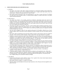
1.09.00 REPORTING SAFETY-RELATED CONDITIONS
The Manager of Gas Systems must submit a written report to the federal and state regulatory agencies if
certain safety-related conditions are not corrected within 5 days after determination. These reportable
conditions are listed below. The Company objective is to have no conditions which require reporting.
Whenever possible such conditions should be repaired within 5 days.
List of Reportable Safety-Related Conditions
Corrosion on gas pipeline operated at 20% or more of SMYS:
a) General corrosion affecting MAOP
b) Localized corrosion pitting where leakage might result
Impairment of serviceability of pipeline or structural integrity, or reliability of LNG facility due to:
a) Unintended movement by environmental causes
b) Abnormal loading by environmental causes
Impairment of structural integrity of LNG facility caused by:
a) Crack
b) Other material defect
Impairment of serviceability of pipeline operating at 20% or more of SMYS caused by:
a) Material defect
b) Physical damage
Pressure rise above MAOP for pipeline, or working pressure for LNG facility plus build-up allowed
for operation of pressure limiting or control devices caused by:
a) Malfunction
b) Operating error
7
Gas Operations and Maintenance Procedures
Rev: 01 Jun 2008
Leak that constitutes an emergency in a:
a) Pipeline
b) LNG facility
Impairment of structural integrity of LNG storage tank due to:
- Inner tank leakage
- Ineffective insulation
- Frost heave
Condition that could lead to an imminent hazard and causes a 20% or more in operating pressure or
shutdown of operation of:
- Pipeline
- LNG facility
Should the conditions listed above exist for more than 5 days, a Safety Conditions Report (see following
pages/topics) must be completed and sent to both federal and state regulatory agencies. To ensure that the
Company meets the reporting deadlines, the report should be transmitted via facsimile to federal and
appropriate state agencies listed on the following page.
A copy of the facsimile should also be mailed to both federal and state agencies at that time.
Prompt notification of emergency situations must still be made to the MDTE for emergency situations
such as:
Certain releases of gas or LNG from a pipeline or LNG facility.
Fires or explosions at Company gas facilities.
Evacuation of a building for gas related reasons.
Service interruption in excess of 50 hours, cumulatively (# of customers/hours).
Fires or explosions which may be the result of the presence of gas.
Significant events in the judgement of the Manager of Gas Systems.
Detailed reporting requirements for the above are provided in the Emergency Procedure Manual. Any
questions regarding conditions which require reporting should be brought to the attention of the Manager
of Gas Systems.
8
Gas Operations and Maintenance Procedures
Rev: 01 Jun 2008
1.10.00 SAFETY-RELATED CONDITION REPORT
TO: Director
RESOURCE MANAGER,
MASS DEPT OF TELECOMMUNICATION &
ENERGY
PHMSA, RSPA
PIPELINE ENGINEERING & SAFETY
DIVISION
U.S. DEPARTMENT OF TRANSPORTATION
ROOM 2335
400 SEVENTH STREET SW
ONE SOUTH STATION
WASHINGTON, DC 20590
BOSTON, MA 02110
FAX (202) 366-7128
FAX (617) 345-9102
UNITIL-FITCHBURG GAS & ELECTRIC LIGHT CO
285 JOHN FITCH HIGHWAY
FITCHBURG, MA 01420
1 888 301-7700
SAFETY-RELATED CONDITION REPORT
DATE OF REPORT: ______________ I D NO. ______________________
DATE FAX RECEIVED: ______________ ORIGINAL: ___________________
REPORTING OFFICIAL's NAME: __________________________________________
TITLE: ___________________________ TELEPHONE: _________________
DETERMINING PERSON's NAME: _________________________________
TITLE: ___________________________ TELEPHONE: _________________
DATE CONDITION DISCOVERED: __________________
DATE CONDITION DETERMINED TO EXIST: ___________________
CONDITION LOCATION:
NATURAL GAS PIPELINE: _______________ LNG FACILITY:______________
CITY: __________________________
SPECIFIC LOCATION: ________________________________________
___________________________________________________________
___________________________________________________________
(1 OF 3 PAGES)
9
Gas Operations and Maintenance Procedures
Rev: 01 Jun 2008
SAFETY-RELATED CONDITION REPORT
(page 2 of 3)
REASON FOR REPORTING (mark all applicable categories)
____ 1. CORROSION ON GAS PIPELINE OPERATED AT 20% OR MORE OF SMYS:
____a) General corrosion affecting MAOP
____b) Localized corrosion pitting where leakage might result.
____ 2. IMPAIRMENT OF SERVICEABILITY OF PIPELINE ____ OR STRUCTURAL INTEGRITY
OR RELIABILITY OF LNG FACILITY ____ DUE TO:
____a) Unintended movement by environmental causes
____b) Abnormal loading by environmental causes
____ 3. IMPAIRMENT OF STRUCTURAL INTEGRITY OF LNG FACILITY CAUSED BY:
____a) Crack
____b) Other material defect
____ 4. IMPAIRMENT OF SERVICEABILITY OF PIPELINE OPERATING AT 20% OR MORE OF
SMYS CAUSED BY:
____a) Material defect
____b) Physical damage
____5. PRESSURE RISE ABOVE MAOP FOR PIPELINE ____, OR WORKING PRESSURE FOR
LNG FACILITY ____ PLUS BUILD-UP ALLOWED FOR OPERATION OF PRESSURE
LIMITING OR CONTROL DEVICES CAUSED BY:
____a) Malfunction
____b) Operating error
____6. LEAK THAT CONSTITUTES AN EMERGENCY IN A:
____a) Pipeline
____b) LNG Facility
____7. IMPAIRMENT OF STRUCTURAL INTEGRITY OF LNG STORAGE TANK DUE TO
____a) Inner tank leakage
____b) Ineffective insulation
____c) Frost heave
____8. CONDITION THAT COULD LEAD TO AN IMMINENT HAZARD AND CAUSES A 20% OR
MORE REDUCTION IN OPERATING PRESSURE OR SHUTDOWN OF OPERATION OF:
____a) Pipeline
____b) LNG Facility
10
Gas Operations and Maintenance Procedures
Rev: 01 Jun 2008
SAFETY-RELATED CONDITION REPORT
(page 3 of 3)
DESCRIPTION OF CONDITION:
_____________________________________________________________________________________________
_____________________________________________________________________________________________
_____________________________________________________________________________________________
______________________________________________________
DISCOVERY CIRCUMSTANCES:
_____________________________________________________________________________________________
_____________________________________________________________________________________________
_____________________________________________________________________________________________
______________________________________________________
SIGNIFICANT EFFECTS ON SAFETY
_____________________________________________________________________________________________
_____________________________________________________________________________________________
_____________________________________________________________________________________________
______________________________________________________
CORRECTIVE ACTION TAKEN:
_____________________________________________________________________________________________
_____________________________________________________________________________________________
_____________________________________________________________________________________________
______________________________________________________
1) REDUCED PRESSURE FROM (psig): ____________ TO (psig): ____________
2) SHUTDOWN: ____________YES _____________ NO
3) DATE ACTION TAKEN: __________________________
PLANNED FOLLOW UP CORRECTIVE ACTION:
_____________________________________________________________________________________________
_____________________________________________________________________________________________
_____________________________________________________________________________________________
______________________________________________________
DATE TO BEGIN: _______________________________________
DATE TO BE COMPLETED BY: ____________________________
11
Gas Operations and Maintenance Procedures
Rev: 01 Jun 2008
1.11.00 EMERGENCY REPAIR OF MAINS AND SERVICES
A segment of pipe that becomes damaged and/or unsafe must be replaced, repaired or removed from
service.
Segments or replaced pipe must be leak-tested according to the appropriate O&M procedures. When
the nature of the repair does not allow in-place pressure testing of the replaced segment, be sure to
pressure-test the segment of repair pipe to at least the pressure and for at least the duration specified
in O&M Procedures 3.31.00 or 3.34.00 before using the pipe for the repair.
Be sure to document that the pipe segment used for repair was properly pressure-tested. It is a
requirement to keep a permanent record of the test. Document the test pressure, test medium (e.g.
air, nitrogen), test duration and the name of the person who conducted the test on the work order.
Do not gas the line until you have located and eliminated each leak that could result in a potential
hazard when gas is introduced into the line.
1.12.00 REGULATOR OR METER STATIONS, VAULTS, PITS OR
CABINETS - GENERAL
All regulator or meter stations, vaults, pits, cabinets or other related facilities shall comply with the
following criteria.
1.12.01 LOCATION
All installations shall be located (so far as practical) - 49 CFR 192.185:
Away from street intersections and paved areas where traffic is heavy or dense.
Away from points of minimum elevation, catch basins or places where access doors or covers of the
installation will be subject to the entrance of surface water.
So as not to conflict with other underground utilities or other subsurface installations.
To provide for ample space to park Company vehicles while work or maintenance is being
performed.
Away from the vehicular traveled way (i.e. tree belt, traffic islands, etc.).
1.12.02 DESIGN
All installations must be designed:
So that there is ample space to properly install, operate and maintain the equipment.
To meet any loads which may be imposed upon the installation, and to protect all equipment?
So that all pipe entering or within the installation is steel with the exception of control lines which
may be stainless steel or copper.
To prevent the passage of gases or liquids through sleeve openings.
To prevent mechanical strains imposed on the pipe where it enters the installation.
To insure that all electrical equipment in the installation complies with the applicable codes.
To prevent connection to foreign underground structures or pipelines.
12
Gas Operations and Maintenance Procedures
Rev: 01 Jun 2008
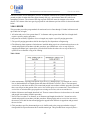
1.12.03 VENTING
When internal volume of the pit exceeds 200 cubic feet:
- The installation shall be vented with 2 ducts, each having the effective area of a 4" diameter pipe.
- The ventilation must be sufficient to prevent the formation of a combustible atmosphere.
- The vent stacks must be high enough above finish grade to safely disperse any gas-air mixture that
may be discharged.
When internal volume is more than 75 cubic feet but less than 200 cubic feet, each opening must
have a tight fitting cover without open holes through which an explosive mixture might be ignited.
There must be a means for testing the internal atmosphere before removing or opening the inlet to
the installation.
If the installation is vented, there must be a means of preventing external sources of ignition from
reaching the atmosphere within the installation.
1.12.04 OVERPRESSURE PROTECTION
At Fitchburg Gas & Electric Light Company gas custody transfer stations, Engineering must review
pressure control design and verify protection on devices are present to ensure stations comply with
D.O.T. Part 192.195 (See note). At a minimum, Engineering will verify for each station that:
The station is designed to prevent unauthorized operation of any valve that will make the pressure
relief or pressure-limiting valve inoperable.
Where relief valves are used, adequate relief capacity is available to prevent the downstream system
pressure from exceeding MAOP. Calculations in support will be reviewed annually and kept on file
in Operations and Engineering.
The Company performs periodic inspections of pressure regulating stations to ensure that the
regulators are performing as designed. Copies of inspection reports will be kept on file at
Operations-Plant Records.
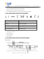
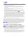
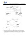
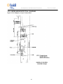
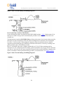
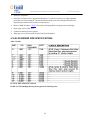
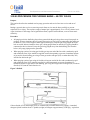
1.15.00 HIGH BTU PIPELINE NATURAL GAS (Air Stabilization)
This is a procedure to address high Btu natural gas from our pipeline suppliers which would not
interchange with the original gas the customers gas burner was adjusted to; a natural gas that exceeds
1080 Btu/cf needs to be diluted with air ( Air Stabilization) to maintain proper burner characteristics and
performance. This procedure also applies to the LNG plant operation in Westminster if high Btu LNG is
received.
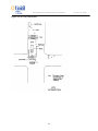
Process to address High Btu natural gas from Tennessee Pipeline
1. Alarm #1- 1080 Btu gas at Tennessee Pipeline
This alarm is programmed in the Scada system at the dispatch center and will monitor the Btu of
incoming gas from Tennessee Pipeline, as the Btu changes, and if the Btu reaches 1080/cf an alarm
will notify the dispatcher and the dispatcher will notify the following people:
Manager of Gas Operations
Manager of Gas Compliance
Supervisor of Gas Production
13
Gas Operations and Maintenance Procedures
Rev: 01 Jun 2008
Sr. Gas Engineer
2. Dispatch to contact Tennessee Pipeline to obtain information about the high Btu gas
3. Dispatch to contact Unitil Customer Service to see if they are receiving any customer calls (if so,
commence air stabilization)
4. Alarm #2- 1090 Btu at Tennessee Pipeline
5. Dispatch to notify the following individuals of the 1090 Btu:
Manager of Gas Operations
Manager of Gas Compliance
Supervisor of Gas Production
Sr. Gas Engineer
6. Commence air stabilization at the LPGA plant (see LPGA emergency manual for procedure)
7. Dispatch to continue monitoring Btu at Tennessee Pipeline
8. Stop air stabilization when LPGA plant Btu is less than 1080 Btu and Tennessee Pipeline Btu is less
than 1080 Btu.
Chapter 2 - Maintenance
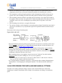
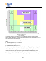
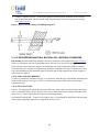
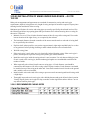
2.01.00 WORK AREA PROTECTION
2.01.01 GENERAL: 49 CFR 192:605(b)
This section outlines the work area protection necessary to protect company employees and pedestrians,
maintain safe traffic control and minimize economic loss.
This section describes typical standards, the use of barricades and other warning devices and in no way
precludes the use of additional or altered controls to meet special field conditions.
2.01.02 PURPOSE:
The fundamental purpose of a work area protection system is to separate the work area from traffic area.
This is accomplished in three ways:
By Warning
By Guiding
By Protecting
No work area protection system is complete without all three.
Warning gives the public notification that they are approaching a work site.
Guiding devices channel traffic safely around the work area. These directions should be simple and clear.
These devices should be easy to see and placed well ahead of the work area. Warning signs should be
placed so as to be visible at all times.
Protection gives safety to the public and employees by the proper placement of vehicles, equipment,
barricades and spoil banks.
14
Gas Operations and Maintenance Procedures
Rev: 01 Jun 2008
2.01.03 BASIC RULES:
Before leaving the yard check the work area protection equipment on the truck. Determine all safety
equipment requirements. These requirements include:
Lights
Signal flags
High flag standards
Warning signs
Extra barricades
Special barricade rope
Extra cones
Flagmen or policemen
On arrival at the job site the truck should be placed as a barricade between the work area and
oncoming traffic.
Look over the work area and plan the arrangement of the protective equipment, taking into account
the following:
The speed and quantity of traffic (on foot and in vehicle)
Curved or straight road
Hilly or level road
Flat or crowned road
Curbs, deep gutters and pedestrian sidewalk access
The location and angles of intersections
Visibility: good or poor
Weather: clear, rain, fog, sleet or snow
Condition of road: dry, wet, icy, slushy or snowy
Day or night
Assign one or more flagmen for temporary protection while setting up the equipment. If conditions
require, permanent flagmen should be used. Request assistance of local and state police when
required.
High visibility vests and/or uniforms shall be worn by workers when exposed to vehicular traffic.
The work areas (described in sketches on the following pages) shall be clearly indicated by barriers,
flags, traffic cones or combinations arranged to safely channel traffic around the area. Traffic cones
should be spaced a maximum of twenty-five (25) feet apart. Advanced warning signs shall be
properly placed to alert drivers to conditions ahead.
Materials or equipment, which may have to be left on the job unattended, shall be placed so that they
afford minimum interference with traffic and blocked so that they cannot be easily moved. Work
area protection shall be placed around the material or equipment.
During hours of darkness, the work area shall be illuminated with electric flashers or combinations
of other approved equipment.
Job site shall be kept clean at all times to avoid tripping, falling or other hazards.
Shoring is to be considered part of work area protection and shall be used as required.
15
Gas Operations and Maintenance Procedures
Rev: 01 Jun 2008
The public shall be guarded from sparks and radiation from welding operations and chips or flying
particles by suitable screens, barriers and warning signs.
Pedestrians shall not be permitted to enter the work area.
Perform all blasting operations in accordance with all prescribed regulations.
2.02.00 WORK AREA PROTECTION EQUIPMENT
Traffic Cones
Flasher Lights
Flags
Steel Plates
Barricades
Traffic Cone Flag Holders
High Flag Standards (Free Standing)
High Visibility Clothing
Flag Standards (For use with barricades) "Soft Trench" Signs
Signs for Highway Work
"Men Working" Signs
Caution Construction Ahead Supports for Highway Signs
Slow Single Lane Ahead
Slow No Passing
End of Construction
Flagman Ahead
2.03.00 WORK AREA PROTECTION PROCEDURES
Figure 2.03.00.1
16
Gas Operations and Maintenance Procedures
Rev: 01 Jun 2008
EARLY WARNING:
Place the first warning device well in advance of job site. A minimum of 150 to 200 feet is recommended
for city work, while 500 to 1,000 feet is recommended for open highways. Place the first warning device
so it can be seen but not hinder the flow of traffic.
2.03.02 USE TRUCK AS SHIELD:
If feasible, place the truck between the flow of traffic and the work area in such a position that the rear of
the truck is facing oncoming traffic. Vehicles with rear mounted backhoes will require additional work
area protection. Signal lights and flashing lights on trucks should be used to provide further protection.
2.03.03 BARRICADING WORK AREA:
Set up adequate work area protection equipment. The main reason for using work area protection
equipment is to prevent accidents.
2.03.04 NARROW STREET:
Narrow streets having two-way traffic need warning signals at both ends of the job site to alert drivers and
give them a chance to pass safely.
2.03.05 EMPLOYEE SAFETY:
All employees shall stay within the protected work area.
2.03.06 SPOIL BANK AS SHIELD:
When possible, locate the spoil bank on the side requiring the most protection.
Figure 2.03.06.1
MINIMIZE CONGESTION:
Keep other vehicles from stopping or parking opposite the job site. Consider use of "No Parking" signs or
barricades to keep work area clear.
2.03.08 REARRANGE PROTECTION:
When necessary, rearrange the work area protection as the job progresses.
17
Gas Operations and Maintenance Procedures
Rev: 01 Jun 2008
2.03.09 BARRICADE REMOVAL:
At the completion of a job, assign a flagman while the work area protection equipment is being removed.
2.03.10 NIGHT PROTECTION:
If the job is to be left for the night, make sure it is adequately protected and that flashing lights are
properly placed. Open lights are not permitted.
2.03.11 STEEL PLATES:
Steel plates may be used to safely cover trenches and maintain vehicular or pedestrian traffic flow. At
night they may be used to permit unobstructed use of street.
2.03.12 MUNICIPAL ASSISTANCE:
Certain operations may require special permission or assistance from municipal authorities. Such
assistance shall be utilized when required.
2.03.13 REGULATIONS:
Federal, state and local rules and regulations regarding protection devices and signs shall be followed.
18
Gas Operations and Maintenance Procedures
2.03.14 WORK AREA PROTECTION - DIAGRAMS
Figure 2.03.14.1 Highway or Open Country Road
19
Rev: 01 Jun 2008
Gas Operations and Maintenance Procedures
Figure 2.03.14.2 Typical Barricading of Opening on Highway at Curve or Hill
20
Rev: 01 Jun 2008
Gas Operations and Maintenance Procedures
Figure 2.03.14.3 City Intersection
21
Rev: 01 Jun 2008
Gas Operations and Maintenance Procedures
Figure 2.03.14.4 Sidewalk Openings
22
Rev: 01 Jun 2008
Gas Operations and Maintenance Procedures
Rev: 01 Jun 2008
Figure 2.03.14.5 City Street
2.04.00 PROTECTING UNDERGROUND FACILITIES
2.04.01 GENERAL 49 CFR 192:605 (b) (3) (4)
State and Federal laws require that individuals, contractors, municipalities, counties and the State
inform the Company of any work to be done near gas facilities.
The Company's program to prevent damage includes, but is not limited to:
- Securing notification of intended construction from individuals, contractors, engineers, architects,
utilities, municipalities, counties, state or federal agencies.
23
Gas Operations and Maintenance Procedures
Rev: 01 Jun 2008
- Notifying the parties involved of the existence and location of Company facilities.
- Marking locations of Company facilities for the contractor at the job site once notified of
construction activity (see O&M Procedure 2.06.00).
All employees should report any construction near our gas facilities.
Upon receipt of a Dig Safe notice, the Dig Safe Coordinator shall determine if gas facilities are
located within the limits of the project. If so, the Dig Safe Coordinator will mark gas facilities within
72 hours as required by Dig Safe laws. Markings shall be placed according to O&M Procedure
2.06.00.
Telephone calls from contractors and others seeking emergency information on gas facilities shall
receive prompt attention.
Letters of notification from contractors and engineering firms must be answered by letter when
required.
The Company will issue maps showing the size and location of underground gas facilities to
municipal, county, state and consulting engineers when requested for specific projects. Maps will be
current and show when last updated.
When possible, a Company representative should confer with the contractor prior to the start of
construction and review the gas facilities that may be involved. He should also inform the contractor
of the care necessary for protecting these facilities.
The Company will mark the location of gas facilities for contractors in the field using yellow flags,
stakes or paint markings. Use pipe finders or other reliable methods to locate gas facilities (see
O&M Procedure 2.06.00).
On large projects where construction prints are available, the Company will give to the contractor a
marked construction print showing the general location of gas facilities. Indicate that prints are for
design use only, not excavation.
Warn contractors to use hand tools for final excavation near a gas facility and to avoid striking it
with excavating equipment, timbers, pipe being installed or loads of backfill. Gas facilities should
not be used to support platforms or other utilities.
Identify construction work, which may involve gas facilities and could create a hazardous situation,
to the contractor's immediate attention. Notify the Manager of Gas Systems or designee
immediately.
2.05.00 DAMAGE PREVENTION PROGRAM
2.05.01 DIG SAFE- 49 CFR 192.614
Title 49 Section 192.614 of the Code of Federal Regulations requires that each operator of a buried
pipeline has and follows a written program to prevent damage from excavation activities. To a large
extent, FG&E is covered by their participation in the Dig Safe One Call system and activities to be
performed by Dig Safe.
Program
Dig Safe and the Massachusetts One Call Underground Damage Prevention system, will identify on
a current basis all persons who normally engage in excavation in the state and contact them annually
24
Gas Operations and Maintenance Procedures
Rev: 01 Jun 2008
to make them aware of the Damage Prevention Program, its purpose, and how to learn the location
of underground pipelines before excavation starts.
The Company will periodically notify the public of the existence of the Damage Prevention
Program, its purpose, and how to learn the location of underground pipelines before excavation
activities are begun.
Dig Safe will continue to receive and record notification of planned excavation activities and
forward that information to the Company.
The Company will notify contractors of its underground piping by marking locations with yellow
spray paint in accordance with Dig Safe conventions within 72 hours after the contractor has called.
Stakes or flags may be used in unpaved areas (see O&M procedure 2.06.00).
If blasting will be part of an excavation, the Company will verify the integrity of its pipeline system
in proximity to the blasting with a survey both before and immediately after the blasting. The survey
will be conducted using combustible gas indicators, flame ionization equipment, infrared equipment
and/or other industry accepted testing equipment. Since the excavator is required to notify Dig Safe
24 hours before blasting, the leak surveyor should meet with the blasting engineer within 24 hours of
the time on the Dig Safe ticket and preferably on the same day that blasting will begin. At the
meeting and prior to the blasting, the leak surveyor should discuss the location and direction of the
blasting with respect to gas facilities. A review of the maps and records should indicate the gas
facilities pressure (e.g. low, intermediate or high pressure) and material (e.g. cast iron, bare steel, and
plastic).
The leak surveyor should also discuss the following with the blasting engineer:
The type and condition of the soil in the area, the size, type, location and direction of the charges and the
possible impact on gas facilities. Based upon this review, the surveyor should conduct a pre-blast leak
survey of gas facilities in proximity of the blasting. Immediately after the blasting, gas facilities closest to
the location and direction of the charges should be resurveyed. If the survey indicates that facilities have
been damaged, the surveyor should investigate and classify the leak according to the O&M Procedures
2.21.00 and 2.22.00 and promptly notify the dispatcher and the Manager of Gas Systems that a crew is
needed at the location to repair the damage to gas facilities caused by blasting activities.
Maintain records to substantiate results of pre- and post-blasting surveys.
2.06.00 GENERAL LOCATING AND MARKING PROCEDURES
CAUTION: These procedures are not designed to accommodate every field condition that might be
encountered in the course of performing a locate. These procedures are to be followed as a prudent
operating practice. Where the guide cannot be applied and your experience cannot resolve the
situation, do not hesitate to seek further specific direction from the Manager of Gas Systems.
Read DIG SAFE ticket thoroughly, specifically the location description, house number, street name
and town. Locate and verify the nearest cross street to the location.
Look for any white layout pre-mark areas. If the DIG SAFE law requires pre-marking in your state
and you don't find any markings, layout the gas locate as usual and document on the ticket that there
were no pre-marks. Do not assume any previous gas markings are still in place and do not assume
previous yellow marks are correct. Confirm and adjust according to your own findings.
25
Gas Operations and Maintenance Procedures
Rev: 01 Jun 2008
Establish a safe operating base. Place your vehicle to protect the anticipated work area. If the job is
of any length, ride the route checking for dogs and other related security or safety issues.
Report premature digging to the Manager of Gas Systems immediately.
Activate safety flashers and wear proper safety gear. Set up cones, barriers and roadway alert devices
as required by state, local and federal mandates.
When possible, talk with contractor and confirm the nature and location of the proposed excavation.
When possible, verify that the excavator understands the location of the facilities and marks that will
be left. Document on the ticket who you spoke with and any long term construction agreements
made.
Look for isolated grounding and connection points for your locating equipment.
Review the plans and sketches. Ensure that the drawing accounts for existing structures. Porches,
patios, fences and driveways are often installed after the gas service. Old buildings are often razed
and replaced in downtown areas and streets are widened. Be aware that Company plans and sketches
may not be complete.
Observe the street in comparison to plotted features. Always look for gas valve boxes, risers and
outside meters. Look for evidence of buried water, sewer, electric, telephone and cable. Look for
new utility construction or repair patches. If necessary, call Plant Records for further record
assistance.
Based on the pipe material to be located, select the proper instrument and locating technique.
Physical direct conductive locating is the preferred technique. Use tracer wire where available for
locating on plastic pipe.
In areas where there are inside meters always attempt to gain access to make physical contact
upstream of any insulator as close as possible to the service entrance at the wall. When unable to get
in, leave a "CGI" card explaining the need to locate the facilities.
Always begin with a 50-foot radius, 360-degree sweep of the area to pick up any multiple signal
paths. Set signal generator/locator antennae as described in the user manual. Ensure that the
equipment is connected with proper continuity. Insure no service or mainline insulators interrupt the
signal circuit. Use caution in determining the signal generating/grounding structure to avoid
confusing the two. Water hydrants, chain link fences and electrical grounding devices should be
suspect when utilities parallel each other - above as well as below ground. If in doubt, call concerns
to the Dig Safe Coordinator before the ticket expires. In all such situations document the particular
concerns on the ticket, who was called, and what was discussed.
Inductive locating should be well thought out. Be aware of other utility structures close by, either
overhead or below ground. Know your locating device in order to keep the required distance from
the transmitter.
Use plans and records as an added means to layout and locate underground facilities. Before you
leave the site be sure that the locate is correct and matches the records, the locating technique and
your observation of the physical surroundings. Document any concerns.
Mark using appropriate marking methods in accordance with current DIG SAFE laws and standards.
Current regulations require using the center line method (Reference 220 CMR 99.05). Mark all
facilities by printing the letter G or the word GAS, the material, and pipe size for facilities over 2"
diameter. If two parallel mains exist in the same area mark both clearly. Weather, flooding or other
26
Gas Operations and Maintenance Procedures
Rev: 01 Jun 2008
field conditions may dictate the mark out materials and methods to be used such as offset stakes,
pole tags and "Stake Chasers".
Mark all service branches at the main. Mark services on curbs and at some offset point outside the
work (on private property if necessary) to preserve the marks.
Paint all valve, drip and test boxes.
Place markings a maximum distance of every 50 feet - you must be able to see a mark in front and a
mark in back of you.
Audit your work for sufficient markings and proper layout. Check marks and satisfy yourself that
you could trace the facilities walking back along the route.
When complete pick up all equipment and supplies used in the work.
Complete work order and all associated documentation. Note any errors found in the maps. Update
maps, service cards and databases as required and file appropriately at the end of the day.
Walk around the truck to see that nothing is in the way or left behind
2.07.00 EXCAVATION PROCEDURE
The following list of items shall be adhered to in all instances where any type of excavation related to gas
facilities is to take place.
Prior to excavation, a check shall be made to insure that all sub-structure utilities or installations are
located (i.e. "Dig Safe" where applicable).
Adequate barrier protection shall be set up to insure safety and proper work area protection in and
around the excavation area.
All boulders, trees or other surface impediments, which will create a hazard in the excavation area,
shall be removed or made safe before excavation begins.
Workers shall make inspections daily and take appropriate steps to make the excavation area safe.
The walls and faces of all excavations in which employees are exposed to danger shall be made safe
by shoring or other suitable means.
In all instances, spoil from the excavation shall be stored and/or retained at least 2 feet or more from
the edge of the excavation.
Diversion ditches or dikes shall be used where the possibility of surface water entering the
excavation occurs.
2.08.00 TRENCHING PROCEDURE
Trenches more than 5 feet in depth shall be shored, laid back to a stable slope, or some other equivalent
means of protection shall be provided where employees may be exposed to moving around or cave-ins
(see table and diagram on next page).
The decision to install shoring, sheeting or other suitable means of protection in trenches less than 5 feet
in depth due to recent excavations, unstable soil conditions, heavy vehicular traffic or other reasons shall
be made by the person in charge at the job site.
27
Gas Operations and Maintenance Procedures
Rev: 01 Jun 2008
When installing shoring and/or sheeting, the following rules shall be adhered to:
All materials used for shoring and/or sheeting shall be in good serviceable condition, and designed
and installed so as to be effective to the bottom of the trench or excavation (see table and diagram on
next page).
In trenches 4 feet in depth or more, a ladder shall be provided so as to require no more than 25 feet
of lateral travel.
Cross braces or trench jacks shall be in a true horizontal position.
Portable trench shields may be used in lieu of shoring and/or sheeting.
Shoring, sheeting or other suitable means of protection from moving ground or cave-ins shall be left
in place until the backfilling is to take place.
Jacks and braces shall be removed starting at the bottom of the trench and moving upwards.
Jacks and braces shall be released slowly and where possible, ropes shall be used to pull the jacks
and braces from the trench.
Table 2.08.00.1 TIMBER TRENCH SHORING - MINIMUM TIMBER REQUIREMENTS*
28
Gas Operations and Maintenance Procedures
Rev: 01 Jun 2008
Table 2.08.00.2 WAREHOUSE INSPECTION OF PLASTIC PIPE
2.09.00 Inspection of Materials- 49 CFR 192.307
When a shipment of plastic main or service pipe is received the shipment shall be inspected to assure that
material is the correct material and free from defects.
A representative from the Stockroom will examine the condition of the pipe surface to ensure there are no
significant scratches or other surface defects. Wall thickness, OD and ID will be checked. The maximum
allowable depth of a slice or scratch on the pipe is 10% of the wall thickness. The maximum variance of
wall thickness and internal diameter is 10%. Questionable material should be brought to the attention of
the Manager of Gas Systems.
If any dimensions are not in compliance with material specifications, the entire lot of pipe shall be
returned to the supplier.
2.10.00 FIELD INSPECTION OF PLASTIC PIPE
The Distribution Project Leader and/or A-Leader shall check the status of work in the field in accordance
with section 2.09.00. He will enforce procedures and examine methods of pipe joining. If in his
estimation a joint or coupling seems suspect he has the authority to remove such joint or coupling.
Joints or couplings may be removed and tested at the discretion of the Project Leader.
2.11.00 DISTRIBUTION SYSTEM SURVEY
(49CFR 192.721, 192.723 220 CMR 101.06(21)) A gas detector survey (using combustible gas
indicators, flame ionization equipment, infrared equipment and/or other industry accepted testing
equipment) shall be conducted on distribution systems in business districts. The survey conducted
should include tests of the atmosphere in gas, electric, telephone, sewer and water system manholes,
catch basins, at cracks in pavement and sidewalks, and at other locations providing an opportunity
for finding gas leaks. Business districts are defined as areas within pavement from building wall to
building wall and/or where the principle commercial activity of the city or town takes place
29
Gas Operations and Maintenance Procedures
Rev: 01 Jun 2008
Distribution system surveys of areas within business districts must be done at least once annually
and at intervals not exceeding 15 months.
Distribution system surveys outside business districts must be done at least once in every
consecutive 24 month period.
Mains in places or on structures where anticipated physical movement or external loading could
cause failure or leakage must be patrolled at least four times each calendar year. The intervals
between patrols cannot exceed 4 ½ months.
Records of leak detection surveys must be made and retained for the period of time prescribed by
regulations.
Class 1 Leaks are to be re-surveyed 30 days after the leak is repaired.
2.12.00 FLAME IONIZATION SURVEY
This survey may be used in either business or non-business areas. Flame ionization equipment is
used to sample the atmosphere at ground level.
When vehicle mounted, the unit is driven from 2 to 5 mph as closely over the main as possible.
Leaks indicated by the flame ionization unit shall be verified and classified by making combustible
gas indicator tests.
Areas to be surveyed shall be indicated on maps and given to the Leak Survey Coordinator prior to
the survey. As each section is surveyed, the Leak Survey Coordinator shall mark the map showing
the area surveyed, the date and his initials. The completed maps shall be filed in the office.
2.13.00 PRE-PAVING SURVEY City and Town Paving Projects
Purpose: The following outlines the procedure for the identification of City and Town paving projects as
well as the subsequent work processes required for maintaining regulatory compliance with chapter
G.L.c.164, §116B.
General:
1. The Gas Operations Manager and/or the Gas Construction and Maintenance Supervisor will contact
each City and Town to outline their paving plans and schedules for the upcoming year.
2. Street restoration projects will be monitored utilizing the Dig Safe Dig Track System. As Dig Safe
requests for street restoration projects, are requested and subsequently completed, the Dig Safe
Technician will utilize close code 11 "street restoration" to close out the Dig Safe ticket. The
Construction and Maintenance Supervisor will query the Dig Track system as often as required to
stay up to date on street restoration projects.
Pre-Paving Leak Survey: 49 CFR 192.721 1. Upon receiving the paving list, the Leak Survey Coordinator will conduct a thorough leak survey of
all mains and services in the proposed area.
2. The leak survey coordinator will communicate, any gas leaks identified, with the Construction and
Maintenance Supervisor.
30
Gas Operations and Maintenance Procedures
Rev: 01 Jun 2008
3. The Construction and Maintenance Supervisor will estimate the number of days required for repairs
as well as the proposed repair schedule.
4. The Construction and Maintenance Supervisor will communicate the required repairs and proposed
timetable to the various Cities and Towns.
5. All repairs shall be completed, prior to paving.
6. At the completion of the repairs, the Leak Survey Coordinator will complete another leak survey and
clear the area.
7. Documentation
Structure Adjustment: (Valve Box) chapter G.L.c.164, § 116B
1. For all street restoration projects the Construction and Maintenance Supervisor will identify the
following:
Streets and proposed limits of the paving projects.
Project Scope (e.g. street only, street and sidewalks, etc)
The type of paving (i.e. cold plane or pulverization).
2. The Supervisor or Project Leader will research maps and records to identify any impacted structures.
3. The Dig Safe Tech will mark and identify all structures (e.g. gate boxes) as part of the Dig Safe mark
out.
4. The Construction and Maintenance Supervisor will coordinate, with the paving contractor, the
adjustment of any affected structures.
5. Structures adjusted
6. Documentation
2.14.00 WINTER PATROL SURVEY- 49 CFR 192.721 (a) (b)
Each year, the Company will conduct winter patrol surveys. These surveys are conducted in order to
detect potentially hazardous situations caused by frost damage. Winter patrol surveys will be conducted
on all mains in business districts and all cast iron mains in both business and non-business districts.
Surveys will be conducted sometime between January 1 and March 1 but only after a reasonable frost
penetration has occurred.
2.15.00 SERVICE LEAK AND CORROSION SURVEY
Each year, the Company will conduct walking surveys to identify potential service line leaks and
corrosion on gas piping. 220 CMR 107.07. At a minimum, one third of the total number of gas services
will be surveyed annually. The surveys will be conducted as follows:
2.15.01 OUTSIDE METERS
Set the flame ionization unit on the most sensitive scale.
Walk the service from the street to the outlet of the meter.
If a leak is detected, set the unit to a less sensitive scale and soap the piping to pinpoint the leak.
31
Gas Operations and Maintenance Procedures
Rev: 01 Jun 2008
Mark the location of the leak whenever possible, note the service address, and notify the dispatcher
or your supervisor.
Inspect the service riser for atmospheric corrosion.
Make sure that the meter stop is easily accessible. If not, notify the Distribution Project Leader so
that appropriate action can be taken.
2.15.02 INSIDE METERS:
Each year the Company will conduct interior gas leak and corrosion surveys of houses or buildings with
inside meters and piping. These surveys will be conducted at a rate such that, at a minimum, one third of
the total of the gas services will be surveyed annually. The leak survey procedure will be as described in
sections 2.17.01 and 2.23.02.
2.16.00 PUBLIC BUILDING INSPECTION- 220 CMR 101.06 (21) (a) (b)
The Company must keep a list of all buildings of public assembly which must be surveyed. The list must
include:
Schools - all school buildings including all institutions of learning from pre-kindergarten through
university level.
Nursing homes, orphanages and homes for the aged.
Hospitals
Theater buildings
Churches
Arenas
Conduct a survey of buildings of public assembly at least once annually 220 CMR 101.06 (21)(a)(b).
Include tests for gas leakage and visual inspection of gas facilities in the immediate area of the service
entrance.
Inform the person in charge of the building the reason for the inspection.
Inspect the service entrance, the service regulator and gas meter installation for severe corrosion or other
unsafe conditions.
Inspect for locking devices on inactive meters and services
Inspect the inside shut-off for condition and accessibility.
Make combustible gas indicator tests at meter installation, at point of entry of gas, water, sewer and duct
lines and at any large cracks along street wall in the basement. Notify dispatcher if leaking gas is found to
be entering building.
Visually inspect regulator vents to assure that they are clear. Any vent located so as to direct blowing gas
toward a window or cause gas to enter the building shall be reported for relocation.
Verify that the curb valve is identifiable and readily accessible whenever a curb valve is installed.
Update and complete all necessary records.
Reference: 220 CMR 101.06 (21)
32
Gas Operations and Maintenance Procedures
Rev: 01 Jun 2008
2.17.00 INTERIOR GAS PIPING CORROSION AND LEAK SURVEY
Massachusetts 220 CMR 107.06 requires the Company to conduct leak and corrosion surveys of gas
company owned interior piping, meter fits and meters. Leak surveys and corrosion inspection should be
conducted at a MINIMUM every 3 years. In addition to 107.06 and whenever a technician visits any
customer's property to perform the following work:
Responding to an odor complaint
Scheduled leak and corrosion inspection
Any type of meter work (e.g. turn-ons, replacements) except reading the meter
Any service work on a furnace or water heater
2.17.01 PROCEDURE:
If the purpose of the visit is to investigate an outdoor leak that does not require inside access, follow
O&M Procedure 2.23.00.
If the purpose of the visit is to investigate an indoor leak, follow O&M Procedure 2.22.00.
If the purpose of the visit is to perform work on the gas meter, furnace or water heater, do the following:
Turn on the combustible gas detection instrument in the outside free air, test batteries and zero the
instrument.
Using the combustible gas detection instrument, leak survey the company owned interior gas piping
and inspect for severe corrosion. Begin at the meter outlet connection and survey the piping back to
where the service line enters the building.
Write down the observed reading (e.g. 0.00% gas) in the space provided or in the comment section
on the work order.
2.17.02 EXCEPTIONS:
No leak survey is needed if:
The gas meter is on a different floor than the furnace or water heater being serviced, or
A locked door prevents access to the meter, fit or interior gas piping or
The employee or company representative is solely reading a meter.
If access is not possible, indicate the reason on your work order
2.18.00 DISTRIBUTION VALVE INSPECTION
General:
Maintain a continuing program to make gate boxes easily and immediately accessible as specified in 49
C.F.R. Part 192 § 192.181, 192.605(a), 192.605(b) and Massachusetts General.Law.c.164,§ 116B.
Locate the valve box. Check existing measurements and correct to field conditions using above
ground reference points if necessary.
Check the valve box with a combustible gas indicator.
If necessary, clean out the valve box so that the valve will be accessible for proper operation.
33
Gas Operations and Maintenance Procedures
Check the valve position.
- Leave valve in same position as found.
- Indicate on the inspection record (below) the position found.
Check the valve operation:
- Normally open valves - crack valve towards closed position and reopen.
- Normally closed valves - crack valve towards open position and reclose.
Lubricate a valve only when it is leaking or if it is difficult to turn.
Align the valve box and adjust it to proper grade.
Recheck the valve box with a combustible gas indicator.
Paint the top of the valve box if required.
Complete the inspection record (below):
34
Rev: 01 Jun 2008
Gas Operations and Maintenance Procedures
Figure 2.18.00.1 - Distribution Valve Inspections Form
35
Rev: 01 Jun 2008
Gas Operations and Maintenance Procedures
Rev: 01 Jun 2008
2.19.00 Critical Valve Inspection
The Company will inspect all critical valves annually, the procedure is the same as for distribution valve
inspections. See section 2:18:00 Distribution Valve Inspection
2.20.00 REPORTED LEAKS ASSOCIATED WITH DAMAGE TO GAS
LINES
On arrival at the location, check all buildings to determine the presence of gas. Follow the steps
outlined in O&M Procedures 2.21.00, 2.22.00 and 2.23.00 as applicable.
Evaluate the damage.
Control the flow of gas using appropriate procedures
Complete the necessary repairs
Complete the required reports.
2.21.00 LEAK CLASSIFICATION
2.21.01 CLASS I LEAKS:
This classification includes gas leaks of sufficient magnitude that immediate repairs are indicated.
Involving public safety where leaking gas is:
Near or entering a building regardless of the magnitude.
In the ground adjacent to a building regardless of the magnitude.
Continuous, positive combustible gas indicator readings in a manhole, or other street opening.
Class 1 Leaks are to be re-surveyed 30 days after the leak is repaired.
2.21.02 CLASS II LEAKS:
This classification includes gas leaks that are not creating a public hazard at the time of detection. These
include gas leaks where:
In the judgement of the field supervisor the leak might develop into a Class I leak should changes
occur, such as:
- Frost penetration.
- Paving installation or repairs.
- Severe drying or compaction of the soil.
- Construction in the area.
- Increases in the normal operating pressure of the piping system.
Report the probable events of concern on the leak report so repairs can be properly scheduled.
The leak pattern of an otherwise Class III leak:
- Has enlarged since the last field check.
36
Gas Operations and Maintenance Procedures
Rev: 01 Jun 2008
- Is abnormal.
- Is contiguous with several Class III leaks.
Gas in the ground near trees, bushes, significant lawn areas or other vegetation is affecting the
growth.
High combustible gas indicator readings are observed in remote areas.
High combustible gas indicator readings are observed in curb boxes or street openings that are not
connected by ducts, pipes or conduits to other street openings or buildings.
2.21.03 CLASS III LEAKS:
This classification includes gas leaks of a small magnitude that are not likely to develop into Class I leaks
before repairs are made or the next leak survey.
2.22.00 LEAK DISPATCHING PRIORITY
Establishing a priority list for repairing gas leaks is to protect the public first and to protect structures and
property second. Leaks that are known to endanger the public have the highest priority over any other
type of work. Leaks are to be repaired in the order that the Grade classifications indicate. If several high
priority leak calls occur at the same time, establish priorities within the Grade classifications to be certain
that the leaks affecting the public are investigated and safely controlled first.
RADIO DISPATCH CODE
CODE 8 - Priority 1 (explosion)
CODE 7 - Priority 1 (gas inside building)
CODE 7 - Priority 2 (gas next to building)
CODE 7 - Priority 3 (gas odor in street)
ALL GAS LEAKS SHOULD BE TREATED AS PRIORITY 1 UNTIL DETERMINED
OTHERWISE.
REPAIR OR CONTROL ALL LEAKS, BEFORE ALL OTHER TYPES OF WORK.
PRIORITY 1 LEAKS:
Any leak that endangers public safety, repair or control gas leak immediately.
PRIORITY 2 LEAKS:
Any leak that is not endangering public safety but is next to a building or large enough to
require immediate attention. Repair as soon as possible.
PRIORITY 3 LEAKS:
Any leak that is not endangering public safety or a building, repair or safely control.
PRIORITY 4 LEAKS:
Any leak that is turned in by survey or employee that is not of a higher priority, repair as
quickly as normal work schedule permits.
PRIORITY 5 LEAKS:
37
Gas Operations and Maintenance Procedures
Rev: 01 Jun 2008
Any leak that has been classified as a minor leak, repair as quickly as normal work schedule
permits or reclassify.
2.23.00 FOREIGN ODOR COMPLAINTS
2.23.01 GENERAL:
Investigate ALL foreign odor complaints immediately.
Immediately after investigation, classify the leak.
Assign a priority level for repairing the leak and dispatch accordingly.
If found to be other than natural gas, notify the proper authority (i.e., Fire Department, Police
Department, City).
2.23.02 BUILDINGS (INSIDE):
Attempt to locate the source of the foreign odor. If the source cannot be located, make the area safe
then notify the Manager of Gas Systems or designee.
If a gas leak that cannot be easily and promptly repaired is found in the piping beyond the meter:
- Turn off the meter.
- Notify the owner, or tenant that the meter will be turned on after the leak has been fixed.
2.23.03 BUILDINGS (OUTSIDE):
Attempt to identify the source of the foreign odor. If the source cannot be located, notify the
dispatcher to send a street crew or flame ionization unit, or the Manager of Gas Systems or designee.
If the source of the foreign odor is identified as gas escaping outside the building, notify the
dispatcher to send a street crew. Wait for the arrival of the crew:
- Examine other buildings on both sides of the street successively until no odor is found in two
consecutive buildings.
- If the leak is in an underground sewer or manhole:
Check other manholes in all directions.
Check all houses on both sides of the street up to the last manhole without gas.
Report the address of all buildings checked and the combustible gas indicator reading obtained.
Ventilate the rooms of all buildings where positive combustible gas indicator readings are obtained.
If ventilation does not reduce the combustible gas indicator readings to a safe level inside the
building, notify all occupants to leave the building. Shut off all gas equipment and appliances with
open flames. Do not use electric switches in the room.
If a building is not occupied, or if it is not certain that the building is occupied, and you consider it
necessary to enter the building immediately to prevent a serious occurrence, call the Fire Department
or Police Department as soon as possible to assist you. Notify your supervisor, as soon thereafter as
possible. Make a full written report of your actions and your reasons for considering them necessary.
38
Gas Operations and Maintenance Procedures
Rev: 01 Jun 2008
2.24.00 RECORDS - LEAKS- 220 CMR 101.06
2.24.01 GENERAL:
Keep a complete written history of times and activities from the first notification of any leak to the final
repair.
2.24.02 ITEMS TO REPORT:
On appropriate forms, report the times of:
- First notification.
- Dispatch.
- Arrival at site.
- Completion of repairs.
- Activities related to the leak.
On appropriate forms, report these other items:
- What was found.
- Apparent cause of leak.
- How repairs were made.
- Injuries (names and addresses) and damages (describe).
- Address and names of owners or tenants.
- Measurements from a permanent reference point of leak and other work on gas facilities.
- Opinion of odor level.
- Estimate of gas pressure.
- Opinion of condition of the exposed pipe.
2.25.00 PINPOINTING FOR LEAKS
Determine the general area of the leak.
Locate all other underground utilities before making test holes.
Drill holes 4 to 12 feet apart determined by the extent of the leak. All holes must be the same depth,
size and spacing.
Test the holes with a combustible gas indicator.
If you can get the largest concentration in a small area, then drill in between holes until you pin it
down to one hole.
If there is a 100% gas concentration in a large area:
- Use aerator to air out holes, then retest to see which one builds up the fastest.
- Test just the top of the hole with the probe. This will at times indicate the greatest concentration.
39
Gas Operations and Maintenance Procedures
Rev: 01 Jun 2008
- Use a film of soap and water or testing liquid on the hole to see if there is a positive pressure.
- Use your sense of smell. Fresh gas will smell differently in the hole closest to the leak.
2.26.00 REPAIR OF GAS LEAK ON DISTRIBUTION MAIN
When the location of a leak has been determined, prepare the leak site as follows:
Check all houses.
Place a fire extinguisher near the work area where it will be accessible for immediate use.
Expose the main at the area of the leak. Be sure to note the condition of the exposed pipe according
to O&M Procedure 2.47.00.
Repair the leak.
Soap test the repair.
Check the adequacy of leak repairs before backfilling. Check the perimeter of the leak with a
combustible gas indicator.
Check all curb boxes of services coming from the main in the area of the leak.
If gas is present in the areas according to the previous two steps, additional leakage is present and
shall be repaired.
If the main segment is made of steel and shows signs of deterioration or mechanical damage, notify
the Manager of Gas Systems or his designee. He will designate the segment as a candidate for
replacement. If the main segment is made of steel and is in very poor condition, ask the Manager of
Gas Systems or designee for authorization to replace the segment. Note the overall condition of the
exposed pipe, any coating damage, any graphitization, the pit depth on steel pipe and describe the
type of corrosion damage (e.g. uniform, general or localized corrosion).
Repairs to metallic mains and services must consider the following: Piping material, i.e. Bare steel,
cast iron, or coated steel; Repair method i.e. stainless steel band clamp, encapsulation device, or steel
pin weldment; Residual gas in the trench atmosphere; Remaining wall (repaired) structural
condition. Based on the above considerations employ the following guidelines:
- On old bare steel mains, clean and coat the pipe with tape or mastic in accordance with the
manufacturers recommended procedure.
- On coated steel pipe that is cathodically protected with anodes, repair any coating damage and
install a Type 1 or 2 test station and 17 lb. anode for "hot spot" protection. Then, run the anode lead
up into the test box.
- On rectifier protected lines, do not install any anodes directly to the pipe. Install a Type 1 or 2 test
station (O&M Procedure 3.29.00) and if the corrosion engineer specifically request - drop an anode
in the trench and run the anode lead up into the test box.
Record locations of repair fittings on the work order.
Backfill the excavation, restore the surface and fill bar holes with approved tar plugs before leaving
the work area.
40
Gas Operations and Maintenance Procedures
Rev: 01 Jun 2008
2.27.00 UPRATING MAINS AND SERVICES TO HIGHER OPERATING PRESSURES
Perform all work to uprate mains and services for higher operating pressures according to existing codes.
Review D.O.T. 49 CFR 192 Subpart K - Uprating-49 CFR 192.551-553 . Retain records of all work
performed as long as facilities remain in operation.
Fitchburg Gas & Electric now uses high-density plastic pipe almost exclusively. Currently, the maximum
allowable operating pressure for this pipe, based on federal and state codes, is up to 100 psig. The
pressure rating may be increased in the future but until further notice, distribution systems will be
designed for operation at under 100 psig.
NOTE: It is possible to apply to the DOT for a waiver allowing an operating pressure of 100 psig or
more.
2.27.01 PLANNING
2.27.01.1 Mains-CFR 49 192.557
Outline the area to be uprated on section maps or other plans that show the distribution system.
Repair or replace badly corroded or leaking mains.
Indicate all mains, valves, drips, purge points and other fittings which should receive individual
attention before pressures are increased.
Check all records to determine manufacturers' pressure ratings for all materials and indicate on plans.
Indicate on plans the methods for isolating and supplying branch connections.
- Mains that can be valved off at tees when supplied by other existing sources.
- Mains which must be cut off and supplied by regulator/relief valve combinations which must be
installed prior to increasing pressures.
2.27.01.2 Services
Prepare a list of all service connections which will be affected by pressure elevation.
Determine which services are active or inactive.
Identify all services by house number in the field, record the locations of outside shutoff valves (i.e.
riser valves and/or curb valves) and locate curb valves if no other outside shutoffs are available.
Notify homeowner or tenant of any proposed service alterations.
Check all records to determine manufacturers' pressure ratings for all materials and indicate on the
list of services any items that should be replaced.
2.27.02 PREPARATION:
2.27.02.1 Mains
Conduct a leak survey and repair any leaks found.
Check all valves as shown on plans of the area uprate.
- Straighten and/or raise to grade boxes as required.
- Grease valves as necessary and operate all valves to insure proper functioning.
- Repack all gate valves with Teflon packing at stuffing boxes.
41
Gas Operations and Maintenance Procedures
Rev: 01 Jun 2008
- Repair any deficiencies.
Remove and/or replace any fittings or materials not suitable for elevated pressures because of low
pressure ratings.
- Gas cocks on drip risers.
- Corporation cocks on purge points.
- Line caps or couplings on dead end stubs.
- Flanges and flanged fittings.
Isolate branch main connections.
- Valve off where possible.
- Install regulator/relief valve combinations where a source of supply is required. Install stopper
fittings, cut off mains and weld caps on main ends where valves can not be utilized. Squeeze and cut
off mains and butt fuse or mechanically join caps on main ends where valves cannot be used.
Install recording gauges to monitor operation.
Install mains and/or equipment necessary to provide required pressures and volumes to system.
2.27.02.2 Services: (100 psig and above)
Install a flow limiter and properly rated service valve at every service. If the maximum operating
pressure of the system exceeds 125 psig or the maximum allowable operating pressure of the house
regulator, whichever is less; install a regulator with an approved overprotection device upstream of
the house regulator.
Check existing regulators and meter sets for proper operation at the new inlet pressures from
regulators that have been installed at the curb valve.
Remove and replace curb valves not suitable for elevated pressures because of lower pressure
ratings.
Abandon inactive services in the uprate area according to O&M Procedure 3.36.00.
Petition appropriate federal and state regulatory agencies for permission to operate plastic pipe at
pressures of 100 psig or above.
2.27.02.3 Services: (under 100 psig)
Where necessary, install a proper pressure-rated curb valve or excess flow valve according to O&M
Procedure 3.37.00 or 3.38.00 and 3.40.00. (Install flow limiter if the service tie-in is worked on).
Check existing regulators and meter sets for proper operation.
Abandon inactive services in the uprate area according to O&M Procedure 3.36.00.
Remove and replace curb valves not suitable for elevated pressures because of lower pressure
ratings.
2.27.03 OPERATION:
2.27.03.1 Mains
Notify the MDTE, in writing, at least seven (7) days before the uprate.
42
Gas Operations and Maintenance Procedures
Rev: 01 Jun 2008
Elevate pressure in increments according to D.O.T. Subpart K of 49 CFR 192. Increase pressure in
either 10-psig increments or in four equal steps, whichever give the fewest steps.
Hold pressure constant after each incremental increase and conduct leak survey over entire segment
of pipeline.
Repair all leaks found that are potentially hazardous before increasing the pressure further. Leaks
determined not to be hazardous need not be repaired if the leak is monitored during the pressure
increase and the leak does not become potentially dangerous.
Maintain pressure recordings during incremental increases.
2.27.03.2 Services: (100 psig and above)
Leak survey each service in conjunction with the leak survey performed on mains and according to
O&M Procedure 2.15.00.
Repair all leaks found that are potentially hazardous before increasing the pressure further. Leaks
determined not to be hazardous need not be repaired if the leak does not become potentially
dangerous.
2.27.03.3 Services: (under 100 psig)
Leak survey each service in conjunction with the leak survey performed on mains and according to
O&M Procedure 2.15.00.
Repair all leaks found that are potentially hazardous before increasing the pressure further. Leaks
determined not to be hazardous need not be repaired if the leak is monitored during the pressure
increase and the leak does not become potentially dangerous.
2.28.00 CAST IRON AND BARE STEEL REPLACEMENT AND
ABANDONMENT PROGRAM
Operation and maintenance of cast iron pipelines is regulated by the Code of Massachusetts Regulations
220 CMR 113.00 Operation, Maintenance, Replacement and Abandonment of Cast-Iron Pipelines. 220
CMR 113.00 1) regulates the operation, maintenance, replacement and abandonment of cast-iron
pipelines that are used to distribute gas; 2) applies to every gas company, municipal gas department or
other person engaged in the distribution of gas within the Commonwealth of Massachusetts.
This procedure addresses 220 CMR 113:00 Operation, Maintenance, Replacement and Abandonment of
Cast Iron Pipelines, Section 113.05: Replacement and Abandonment Program and Procedures. FG&E,
has developed and implemented this program to evaluate cast iron pipe and prioritize for repair
replacement or abandonment.
The regulation calls for the replacement or abandonment of all cast iron pipe with a nominal diameter of
eight inches or less that is known, or has been determined, to have been installed before 1860.
Purpose
Establish a standardized program and procedure for the replacement of cast iron and bare steel low
pressure mains and services. To insure consistency and a best practices approach towards maintaining a
safe and reliable gas distribution system.
The ultimate goal of this program is to quantify, prioritize and control the risk associated with an event on
any given street within the FG&E low pressure cast iron system. The statistically based risk assessment
43
Gas Operations and Maintenance Procedures
Rev: 01 Jun 2008
approach will be used to prioritize projects for repair or replacement decisions. This decision making
approach will have an impact of reducing risk based pipe segments upon the probability of an event and
the impact if an event were to occur.
Scope
This document (appendix D) describes the methodology used for categorizing and prioritizing streets for
repair or replacement. This document will describe the two aspects of pipe prioritization and replacement
methodology. This statistically based risk assessment model uses the complete set of mains data available
in FG&Egas infrastructure database (GIDB).
First, a risk management approach has been developed incorporating probability and impact into the
prioritization matrix. The risk assessment matrix is designed as a tool to assist with prioritizing the repair
or replacement of individual streets based upon historical performance and class location. This will
produce a list of potential mains repair or replacement decisions to be made.
An ideal risk management, a prioritization process is followed whereby the risks with the greatest loss
and the greatest probability of occurring are handled first, and risks with lower probability of occurrence
and lower loss are handled later. This approach will provide a standard prioritization methodology for the
repair or replacement of cast iron and bare steel low pressure mains and services. The risk matrix
presented later in the document (Appendix D) will put some generic guidelines around defining levels of
risk.
Second, once a prioritized list is developed, an economical repair or replacement decision is required on
those streets where the risk equation is too high. Operational and Engineering judgment is required to
determine if repair or a replacement required and when is the best time to implement the repair or
replacement.
Risk Assessment
A risk assessment approach has been developed to asses the integrity of the cast iron and bare steel low
pressure gas mains installed on the cast iron system. Risk assessment enables planning, monitoring and
management of risk across the bare steel and cast iron mains installed on the low pressure system.
An event, as used in this model, is defined as either 1) a bell joint leak, or bare steel leak, or 2) a cracked
main. This best practice approach combines the impact of an event and the probability of an event into
one measurable risk factor.
Risk Equation: REs = IEs * PEs
Where:
REs = Risk Associated with Event
IEs = Impact of an Event
PEs = Probability of an Event
In the assessment process it is critical to make the best educated evaluation possible in order to properly
prioritize the implementation of the risk management plan. In the following sections, each component of
the risk equation will be described. All of the data used for this analysis is recorded and kept up to date in
Unitil Gas Infrastructure Database (GIDB).
Impact of Event
The impact of an event occurring is the first consideration in this risk management approach. Impact of an
event is often quite difficult to quantify. For an event on a low pressure gas system, the following facts
44
Gas Operations and Maintenance Procedures
Rev: 01 Jun 2008
could be considered: (proximity to dwellings, number of customers located within a given distance,
amount and type of cover over mains, number of basements within a given distance, etc.).
It is apparent that the impact of an event is relative to population densities near pipeline routes and other
environmental factors. Public safety is considered the highest priority with respect to the impact of any
given event.
The impact of an event in this risk model is defined by class location. The Code of Federal Regulations
(49 CFR 192.5) defines class location into 4 categories (1 = low impact and 4 = high impact): The
complete Risk Assessment description is in Appendix D.
Probability of Event
The primary objective of this part of the risk equation is to estimate the probability of an event occurring.
An event in this model is defined as 1) a leak (bell joint leak on cast iron mains or corrosion leak on bare
steel) or 2) a cracked main. The probability calculation is a combined probability of leaks and cracked
mains on any given street.
On any given street, the probability or frequency of an event may be affected by frequent construction
activity, change in traffic patterns, frost heaves, third party damage, etc. This model uses a complete set of
data from the GIDB to develop the statically based approach to calculate the probability of an event
occurring on any given street.
The probability of an event occurring is based upon the historical performance of each street in the low
pressure system. The historical performance of any given street is compared to itself in this model. There
may be streets with multiple mains installed. This information is included in the data because the total
length of main is greater than the length of the street.
The probability of an event equation is shown below. This equation is based upon the probability addition
rule to determine the probability that leak or a crack occurs or both occur.
PEs = ( K2 * PLs) + PCs – P(L+C)s
Where:
PEs = Relative probability of an event on a given street
PLs = Relative probability of leak on a given street per 1000' of installed pipe
PCs = Relative probability of cracked main on a given street per 1000'
P(L+C)s = Relative probability of leak and cracked main on a given street per 1000'
K2 = Constant for leak within past 2 years (0 = no, 1 = yes)
In addition, a means of weighting recent leaks with a higher than past repaired leaks is required since the
leak data does not specify active versus repaired leaks. This is accomplished with a constant K2. This
constant is used to identify streets that have experienced leaks in the past two years.
Appendix D describes the derivation of each probability calculation.
2.28.01 THE PROGRAM
Certain segments of cast iron pipe are identified as candidates for replacement based upon certain
selection criteria. These pipe segments are based upon risk analysis, pipe performance, maintenance
history, encroachment and other operational factors listed below. Based on these characteristics, The pipe
segment(s) found to be more likely associated with a leak or break and associated with higher risk in the
45
Gas Operations and Maintenance Procedures
Rev: 01 Jun 2008
event of a leak or break are considered first, and for those characteristics associated with economic
benefit to the company are considered last.
2.28.01.1 Selection Criteria
Each segment of cast iron pipe satisfying one or more of the following criteria is selected for further
analysis: The following factors may be given consideration in making the repair or replace decision.
Risk analysis
Planned municipal projects in the area
Encroachment
Quantity of known existing leaks
Condition of main (past leak repair, corrosion or graphitization)
Planned system improvements in the area
System design criteria
Location of main (street, sidewalk or easement)
Time of year
2.28.01.2 Prioritization of Pipe Segments
Prioritization of pipe segment replacement is done annually by Engineering and Operations on a three
year forecast basis. The prioritization is based upon ranking the pipe segments that satisfy the selection
criteria above.
2.28.01.3 Development of Replacement Schedule
Develop a schedule for the replacement or abandonment of specific cast iron pipe segments.
Based on the CI Risk assessment resultant prioritization of pipe segments of cast iron or bare steel
pipe for replacement.
Assess the impact of any other selection criteria affecting the cast iron segment.
Modify the schedule to allow for sound engineering judgment. Document the rationale for the
change.
2.28.01.4 Administration
Develop a new three year schedule each calendar year. It is recommended that the schedule be updated in
the beginning of the year prior to the budgeting process and for leak and break history surfacing in the
winter months to be evaluated prior to the construction season.
Annual Review of Procedures
Review this procedure, 2.28.00, and modify accordingly at least once each calendar year or more
frequently if needed.
Record Keeping
Maintain accurate and readily accessible records in the GIDB.
46
Gas Operations and Maintenance Procedures
Rev: 01 Jun 2008
2.29.00 CORROSION CONTROL MONITORING AND RECORD
KEEPING -CFR 192.453
2.29.01 MONITORING:- CFR 192.465
Each cathodiclly protected main more than 100 feet long must be surveyed at least once each
calendar year, but at intervals not exceeding 15 months, to determine if the cathodic protection meets
the requirements listed below.
Each cathodically protected service line or main under 100 feet long must be surveyed on a 10%
sample basis annually, so that the entire system is surveyed every ten years.
Each cathodic protection rectifier or other impressed current power source must be inspected 6 times
annually, but at intervals not exceeding 2 ½ months, to insure that it is operating properly.
Each reverse current switch and interference bond whose failure would jeopardize a structure must
be electrically checked for proper performance 6 times annually, but at intervals not exceeding 2 ½
months. All other interference bonds must be checked at least once each calendar year, but at
intervals not exceeding 15 months.
Electrical measurements used to assure continuity of cathodic protection must meet one or more of
the following criteria:
- A minimum negative voltage of 0.85V with reference to a saturated copper-copper sulfate half cell
with the protective current applied.
- A minimum negative polarization shift (decay) of 100 milivolts when the protective current is
interrupted.
- A voltage at least as negative as that originally established at the beginning of the Tafel segment of
the E-Long-I current.
- A net protective current from the electrolyte into the structure surface as measured by an earth
current technique applied at predetermined current discharge (anodic) points of the structure.
2.29.02 REPAIRS:- CFR 192.485
Engineering and Operations are both responsible for evaluating test results, determining what
corrective action is necessary and initiating repairs. Operations will track the test date, repair action
specified, date assigned and date completed for corrosion control repairs to the following:
- Separately protected services
- Separately protected main sections less than 100 feet long
- Rectifiers and other impressed current power sources
- Reverse current switches, diodes and/or interference bonds
Repairs must be completed either before the next scheduled test or within a year of the test date,
whichever comes first. Should any condition cause an immediate or imminent hazard to the public,
repairs should be initiated and completed as soon as possible.
Repairs to customer lines that "can not be shut down" will be made on the same schedule outlined
above by attempting to work closely with the customer. The Company will make every effort to
comply with the customer's need for continued gas service. If no mutually agreeable shutdown can
47
Gas Operations and Maintenance Procedures
Rev: 01 Jun 2008
be arranged, the Company will shut down the service and make repairs necessary to assure continued
safe operation of the service line.
2.29.03 RECORD KEEPING: - CFR 192.491
Each of the following records must be retained for as long as the pipeline remains in service.
Records or maps must be maintained to show the location of cathodically protected piping, cathodic
protection facilities, and any foreign structures bonded to the cathodic protection system.
Records of each test, survey, or inspection must be kept in sufficient detail to demonstrate the
adequacy of the corrosion control measures, or that a corrosive condition does not exist.
Records of repairs covered in this section under the heading REPAIRS.
2.30.00 ATMOSPHERIC CORROSION - CFR 192.481
Each above ground gas pipeline or any gas related piping system exposed to atmosphere must be
inspected, at intervals not exceeding three years, to ensure it is protected with a material to prevent
atmospheric corrosion.
Atmospheric corrosion is best found by visual inspection and examination. Exposed piping should be
inspected for the following:
The protective coating on the pipe should be in good condition; if not, schedule the coating for repair
or replacement.
All metallic pipe supports and restraining devices, including hangers, rollers, wear plates, etc.,
should be protected from corrosion. Attach protective sleeves to pipe where contact with rollers or
clamps would damage the coating.
All expansion joints and compression couplings should be properly coated and checked for gas
tightness and proper operation of the expansion joint.
Cathodically protected pipe should be electrically isolated from metallic bridge structures, pipe
supports, pilings and reinforced concrete foundations. Piping may be attached directly to the bridge
without insulation if insulating devices are installed at each end of the bridge.
Note results of the inspection and any recommended maintenance work on the Atmospheric Corrosion
Control Survey Report form.
Record any scheduled maintenance work performed on the work order form.
2.31.00 PRECAUTIONS FOR UNSAFE GAS ACCUMULATION IN
TRENCHES
These procedures are intended to protect workers when working in trenches in which unsafe
accumulations of vapor or gas may exist. In trenches where an oxygen deficiency or a hazardous
atmosphere could reasonably be expected, test the atmosphere in the excavation with a combustible gas
indicator before entering. Employees shall use approved breathing apparatus as required. Emergency
rescue equipment, such as a harness and line or a lanyard shall be readily available where hazardous
atmospheric conditions may reasonably be expected to develop during work in a trench. The equipment
shall be attended when in use.
48
Gas Operations and Maintenance Procedures
Rev: 01 Jun 2008
2.31.01 Purpose
This policy outlines the measures that field personnel must take to avoid potential injury when working in
or around blowing gas or conducting high risk activities in an outside atmosphere that is considered
hazardous.
2.31.02 General Information
Natural gas burns with a flame temperature of 2200 degrees Fahrenheit. At such temperatures, even an
ignition of short duration (flash) will cause severe burns to exposed flesh. Workers who are not properly
protected may inhale a potentially flammable concentration of gas. If an ignition occurs, the flame may
follow the airway passages into the lungs resulting in potentially fatal respiratory system injury.
2.31.03 Definition(s)
Blowing Gas: A release of gas that can be seen, heard or felt.
Controlled Blowing Gas: The intentional release of gas which is controlled by utilizing a valve,
squeeze tool, vent stack, or other methods.
Uncontrolled Blowing Gas: The unintentional release of gas which is not controlled with a valve,
squeeze tool, vent stack, etc.
Short duration or “Flash”: An ignition that typically lasts less than (3) seconds that is primarily a
result of the exhaustion of available fuel.
Sustained burn: Where adequate fuel supplies support continued combustion and exposure would be
equal to the required extraction time from the excavation.
Hazardous Outdoor Atmosphere: Any location where there is uncontrolled blowing gas, identified
high risk activities, or there is a gas reading of 40% LEL (2% gas-in-air) or greater where the work is
being performed as measured with a Combustible Gas Indicator (CGI).
Level 1 PPE: Single layer F.R. coveralls, carbon head sock, goggles, work gloves and hard hats.
Level 2 PPE: Insulated FR coveralls, carbon head sock, insulated gloves, supplied air equipment,
rescue harness retrieval system and hard hats.
2.31.04 Identifying Hazardous Outside Atmospheres
Any location where there is uncontrolled blowing gas, identified high risk activities, or there is a reading
of 40% LEL (2% gas-in-air) or greater where the work is being performed as measured with a
Combustible Gas Indicator (CGI) is considered hazardous. Appropriate PPE is required when working in
an identified hazardous atmosphere.
The following are examples of high risk situations where the atmosphere would be considered hazardous
(with or with-out gas-in-air readings of 40% LEL or greater).
Third party damage to a gas service or main.
Damage to a meter set, meter riser or other gas facility.
Cracked cast iron or ductile mains.
Changing a gas service valve “on the fly”.
A regulator venting in full relief.
49
Gas Operations and Maintenance Procedures
Rev: 01 Jun 2008
Repairing a gas leak on any facility where gas-in-air readings are 40% LEL or greater in the work
area.
Gas bleed-by on a bagging operation or line stopper where there is a gas-in-air reading of 40% LEL
or greater in the work area.
The following are examples where the atmosphere would not be considered hazardous because of the
techniques or tools utilized in the process:
Purging a service or main through a valve or grounded squeeze tool that is vented, utilizing a
properly grounded vent stack.
Repairing a gas leak on any facility where gas-in-air readings are less than 40% LEL in the work
area (with the exception of performing high risk activities).
Gas bleed-by on a LP bagging operation or line stopper where there is a gas-in-air reading of less
than 40% LEL in the work area.
2.31.05 PPE Requirements
Level 1 PPE: Single layer F.R. coveralls, carbon head sock, goggles, work gloves and hard hats.
All high risk activities that are considered hazardous atmospheres.
Gas readings of between 40% LEL (2% gas-in-air) to 80% LEL (4% gas-in-air).
If in the opinion of the Distribution Supervisor, Utility Worker Lead, or employee feels that the task
at hand could potentially lead to a hazardous situation.
**All field personnel within the work zone will be required to wear Level 1 PPE at all times.
**All field personnel will be required to have Level 1 PPE with them at all times while working.
Level 2 PPE: Insulated FR coveralls, carbon head sock, insulated gloves, supplied air equipment, rescue
harness retrieval system and hard hats.
If a gas reading of 80% LEL (4% gas-in-air) or greater is measured gas field personnel must
immediately remove themselves from the area and suit up in Level 2 PPE prior to continuing work.
**All level 2 PPE responses require direct supervisory/managerial oversight
2.31.06 Minimum 20’ Safety Perimeter
If the blowing gas condition is the result of third party damage it is subject to rapid changes in conditions.
Gas field personnel must establish a minimum safe zone perimeter of 20’ from the location, regardless of
the gas-in-air readings. Any gas field personnel, supervisors, etc who are within this 20’ safe zone
perimeter are required to wear a minimum of Level 1 PPE until the blowing gas is stopped. If gas
readings indicate 80% LEL or greater Level 2 protection is required.
2.31.07 Make Safe Response
Non gas field personnel dispatched to the scene to make the area safe, that do not have access to a CGI or
Level 1 PPE must maintain a minimum 20’ safe distance from the cut main, service or suspected area of
the uncontrolled blowing gas. Non-gas field personnel should keep excavators, emergency response
personnel and the general public at a safe distance and upwind of the blowing gas until qualified
personnel arrive.
50
Gas Operations and Maintenance Procedures
Rev: 01 Jun 2008
2.31.08 Working Within a Hazardous Atmosphere
When blowing gas has been reported, observed, heard or otherwise encountered, a hazardous atmosphere
will be present. When ever possible, gas field personnel should always explore all available options to
control blowing gas and to make repairs in a gas free atmosphere.
The following techniques may be used to establish a gas free atmosphere:
Excavate and squeeze pipe in a gas free atmosphere.
Utilize isolation valves.
Excavate and use control fitting(s) in a gas free environment.
If it is not practical or possible to control blowing gas from a gas free atmosphere, gas field personnel
may be required to work in a hazardous work zone. In these situations safety measures must be taken to
prevent a potential injury. Gas field personnel must:
Define the limits of the hazardous atmosphere by using a CGI.
Continue to monitor the atmosphere, in the work zone, to detect possible changes in conditions.
Monitor the surrounding area with the CGI. Be aware of any changing conditions, such as wind and
weather, which may alter the gas concentration or spread it to other areas.
Establish a means of exiting the excavation.
Establish and review a rescue plan.
Place a safety observer outside the excavation to monitor the atmosphere inside the excavation and
to be available to assist in use of rescue equipment, operation of a fire extinguisher, or otherwise
assist in a rescue.
Minimize sources of ignition in and around the facility.
Take actions to reduce the accumulation of gas or vapors, such as:
Reducing pressure in the facility.
Ventilating the work area.
Take preventative actions to minimize the possibility of ignition through static electricity. Follow
O&M procedure 2.42.00 for proper grounding protocols.
If a reading of 80% LEL (4.0% gas-in-air) or greater is measured, gas field personnel must
immediately remove themselves from the area and suit up in Level 2 PPE before continuing.
Level 2 PPE response requires direct supervisory oversight. If a level 2 response is required the crew
leader should immediately request a supervisor to respond.
2.31.09 Storage, Availability and Care of F.R. P.P.E
Level 1 PPE: Single layer FR coveralls, head socks and goggles shall be assigned to all field
personnel responding to gas emergencies and carried with them so as to be readily available when
required to work in a hazardous atmosphere. When not in use, these items will be protected and kept
in storage bags to prevent soiling or damage. FR coveralls shall be laundered as necessary following
the laundering instructions on the apparel label. FR coveralls and head socks shall not be worn
simply for warmth or for general-purpose everyday use such as protecting other clothing.
51
Gas Operations and Maintenance Procedures
Rev: 01 Jun 2008
Level 2 PPE: Level 2 PPE shall be assigned to the Gas Construction & Maintenance Supervisor and
stored at the JFH facility. The Gas Supervisor is responsible to ensure that this equipment is readily
available and at all work locations where field personnel are required to work in hazardous
atmospheres that warrant this level of response. When not in use, these items will be protected and
stored in appropriate storage containers in the rapid response safety trailer. Insulated FR coveralls
and insulated FR hard hat liners should not be compacted when stored. Compaction greatly reduces
the thermal protection of the material. Supplied air equipment should be stored in such a manner to
not deform the face mask or kink the air lines. Insulated FR coveralls and insulated FR hard hat
liners shall be laundered as necessary following the laundering instructions on the apparel label.
2.32.00 PROCEDURE FOR INVESTIGATION OF FAILURES- CFR
192.2515
2.32.01 DEFINITION:
Failure is defined as an incident that:
Caused a death or personal injury resulting in hospitalization.
Resulted in gas from an uncontrolled source igniting.
Caused estimated damage to the property of the operator, or others, of a total of $50,000 or more.
Caused interruption of supply to a section or threatened system reliability.
Required extraordinary actions to be taken.
2.32.02 OBJECTIVE:
To determine the cause of a failure meeting the above criteria so that corrective action can be taken to
minimize the possibility of a recurrence or to minimize the consequences should there be recurrence.
2.32.03 PROCEDURE:
As soon as the area has been made safe, the Manager of Gas Systems or designee shall have sufficient
photographs taken to record the situation at that time. The Manager of Gas Systems or designee is
responsible for taking samples for laboratory analysis, if appropriate. The Manager of Gas Systems or
designee shall make sure that all required inspections and tests and their results are recorded, and shall
prepare a summary report covering the incident. If the cause of the incident is not readily identifiable, the
Manager of Gas Systems or designee will take care to maintain the area in as undisturbed a condition as
possible until further investigation may be undertaken.
For any failure, submit a report to the Manager of Gas Systems or Director of Operations within 24 hours.
The report shall consist of a description of the incident, a statement of the cause of failure, and any
corrective recommendations.
2.33.00 CONFINED SPACE ENTRY
Follow these procedures when entering:
A regulator pit which is accessed through a manhole cover,
A LNG plant absorber/dehydrator or other equipment accessed through a manhole cover,
A large commercial boiler for natural gas retrofit or
52
Gas Operations and Maintenance Procedures
Rev: 01 Jun 2008
Other confined areas accessed through a manhole cover.
2.33.01 PREPARATION:
Set up work area protection in accordance with applicable Company safety standards.
Keep all sources of ignition away from the work area.
Take care to prevent engine exhaust from entering the confined area.
Test for the presence of combustible gas and available oxygen with a confined space entry gas meter
by using available openings.
- If the oxygen content in the confined space is less than 19.5 percent, ventilate the confined area for
five minutes and retest the confined space.
- If combustible gas is indicated, carefully remove the cover or open the entry way and ventilate the
confined area for five minutes and then retest with the combustible gas indicator.
- If the reading on the combustible gas indicator is more than 10% of lower explosive limit, determine
how gas is entering confined area.
- If gas is entering confined area, DO NOT enter confined area but report leak to dispatcher for
follow up. DO NOT enter confined area until leak is repaired.
- If the leak is on the gas piping, force-ventilate the confined area before entering and while making
repairs.
If the reading on the combustible gas indicator is 10% of the lower explosive limit or less, the
confined area may be entered provided that forced ventilation continues.
A full body harness shall be worn by the employee entering the confined area.
Do not place materials, tools or equipment near the confined area where they could cause tripping or
other type hazards.
Do not weld in the confined area without first obtaining approval.
2.33.02 PROCEDURE:
At a minimum, a two-person team is required. The team is comprised of an entrant and an attendant.
The sole job of the attendant is to monitor the condition of the space and the entrant inside the
confined space and to terminate the entry should conditions warrant. The attendant may not enter the
confined space and may not leave the monitoring role (e.g. to get a tool, answer the radio or for any
other reason) for even a moment while the entrant remains inside the confined space.
The entrant must wear a full body harness with a D-ring on the back and remain attached to a winch
line, in the case of a manhole access, or a tag line held by the attendant in the case of a boiler entry.
Body belts and wristlets are not allowed as substitutes for a full body harness.
The entrant into a manhole accessed confined space must also wear all required personal protective
equipment..
2.34.00 REGULATOR PERFORMANCE TEST - ANNUAL- CFR 192.
Regulators shall be subjected, annually, to a systematic performance test to determine that they are in
proper operating condition.
53
Gas Operations and Maintenance Procedures
Record inlet pressure.
Record outlet pressure.
Visually check the condition of the regulator and observe for proper functioning.
Check the regulator for tightness:
Rev: 01 Jun 2008
- On a self-operated regulator, change the setting and see if the regulator will lock off.
- On a pilot-operated regulator, change the setting on the pilot regulator and see if the main regulator
will lock off.
Check the regulator for sticking. This can be observed from an erratic line on a pressure chart.
Reset the regulator and see that it is at the correct operating pressure.
Check vent and control lines for blockage.
Clean all filter elements.
Record the test on the proper forms.
2.35.00 INTERNAL INSPECTION OF REGULATORS AT GATE
STATIONS
CFR 192.739. This procedure applies to maintenance and inspection of regulators at gate stations. Refer
to and follow the manufacturer's procedures.
Each regulator shall be inspected annually to determine that it is properly installed, protected from dirt,
liquids or other conditions that might prevent the proper operation of the regulator. An internal inspection
shall be conducted and the necessary parts repaired or replaced. This inspection shall be conducted in
accordance with the following procedure:
Notify Dispatch of planned work.
Monitor pressures during inspection.
If a bypass valve exists, open as necessary to maintain outlet pressure while inspection is being
made.
Isolate the regulator by closing appropriate main line shutoff and control line valves in the
appropriate sequence. Follow manufacturer's instructions for taking regulator out of service. Test to
be sure the regulator has been completely isolated by opening a vent valve or, as a last resort, by
disconnecting a static line before disassembling equipment.
Remove inspection plates or disassemble regulator body on main line and control regulators to
inspect gas flow restricting devices (orifices, valve discs, "O" rings, tubes, etc.) and diaphragm link
for wear.
Pressure test or visually inspect all diaphragms for tightness.
Check regulator vent lines, all control lines, and differential control restricting devices (needle
valves, adjustable variable orifices, etc.) for stoppage.
Reassemble regulator.
Pressure test regulator for leakage.
54
Gas Operations and Maintenance Procedures
Rev: 01 Jun 2008
Follow manufacturer's instructions for putting regulator into service. Open appropriate control lines
and main line valves in the appropriate sequence.
Set regulator to desired pressure.
If bypass exists, close valve.
Check regulator setting to function at the correct operating pressure:
Self-operated regulator - change setting on pilot regulator and see if main regulator will follow
change and lock off.
Reset regulator to desired operating pressure.
Notify Dispatch at completion of inspection.
Note results of inspection and work performed on the appropriate forms.
2.36.00 INTERNAL REGULATOR INSPECTION (REGULATOR
STATIONS)
CFR 192.739, Each regulator shall be inspected every five years to determine that it is properly installed,
protected from dirt, liquids or other conditions that might prevent the proper operation of the regulator.
An internal inspection shall be conducted and the necessary parts repaired or replaced. This inspection
shall be conducted in accordance with the following procedure:
Notify dispatch of planned work.
Monitor pressures during inspection.
If a bypass valve exists, open as necessary to maintain outlet pressure while inspection is being
made.
Isolate the regulator by closing appropriate main line shutoff and control line valves in the
appropriate sequence. Follow manufacturer's instructions for taking regulator out of service. Test to
be sure the regulator has been completely isolated by opening a vent valve or, as a last resort, by
disconnecting a static line before disassembling equipment.
Remove inspection plates or disassemble regulator body on main line and control regulators to
inspect gas flow restricting devices (orifices, valve discs, "O" rings, tubes, etc.) and diaphragm link
for wear.
Pressure test or visually inspect all diaphragms for tightness.
Check regulator vent lines, all control lines and differential control restricting devices (needle valves,
adjustable variable orifices, etc.) for stoppage.
Reassemble regulator.
Pressure test regulator for leakage.
Follow manufacturer's instructions for putting regulator into service. Open appropriate control lines
and main line valves in the appropriate sequence.
Set regulator to desired pressure.
If bypass exists, close valve.
55
Gas Operations and Maintenance Procedures
Rev: 01 Jun 2008
Check regulator setting to function at the correct operating pressure.
- Self-operated regulator - change spring setting and see if regulator will follow change and lock off.
- Pilot-operated regulator - change setting on pilot regulator and see if main regulator will follow
change and lock off.
Reset regulator to desired operating pressure.
Notify Dispatch at completion of inspection.
Note results of inspection and work performed on the appropriate forms.
2.37.00 RELIEF VALVE INSPECTION AND TESTING - ANNUAL
CFR 192.743. Each relief valve shall be subjected to a systematic inspection and test annually, in
accordance with the following procedure.
The inspection shall consist of a check to insure that the relief valve is:
In good mechanical condition.
Set to function at the correct pressure.
Adequate from the standpoint of capacity and reliability of operation for the service in which it is
employed. (See Item III)
Properly installed and protected from dirt, liquids or other conditions that might prevent proper
operation.
The test, if feasible, shall consist of the following:
Check records for pressure at which valve should relieve.
Isolate the relief valve from the system it is designed to protect. In most cases, this can be done by
unlocking and closing the valve ahead of the relief valve.
Connect a temporary line from a pressure supply to the piping between the relief valve and the now
closed valve ahead of it. This pressure supply may be existing gas pressure before a regulator, an air
tank, a nitrogen bottle or other device with a pressure greater than the relief pressure. This temporary
line should have a pressure gauge on it.
Turn on the pressure supply and operate the relief valve. Take note of the pressure at which the valve
relieves. Any serious deviation from the desired relief pressure should be corrected.
Shut off the supply pressure and observe the gauge still hooked into the piping before the relief
valve. A constant pressure reading on the gauge indicates a positive seal on the relief valve.
Disconnect the supply line from the relief valve piping and close off the outlet in piping.
Open the valve ahead of the relief valve and lock, or tag, with warning to prevent change of position.
The test, if not feasible, shall consist of the following:
Recalculation of the required capacity of the relieving device at each station must be made at
intervals not exceeding 15 months but at least once each calendar year and these required capacities
compared with the rated or experimentally determined relieving capacity of the device for the
operating conditions under which it works. After initial calculations, subsequent calculations are not
required if the review documents that parameters have not changed in a manner that would cause the
56
Gas Operations and Maintenance Procedures
Rev: 01 Jun 2008
capacity to be less than required. If the relieving device is of insufficient capacity, a new or
additional device must be installed to provide the additional capacity required.
A record of the inspection, test or relocation, and all changes or repairs shall be completed and turned into
the appropriate department where it will be maintained for the life of the device.
2.38.00 INSTALLATION OF FITTINGS AND TAPPING A METALLIC
MAIN
2.38.01 SELF TAPPING TEE ON STEEL MAIN- CFR 192.367
Expose the main and prepare it for the connection.
Fabricate stub using self-tapping tee and appropriate device.
Extract cutter from tapping tee before positioning the tee on main and welding. Make sure it is
greased.
Place a fire extinguisher near the work area where it will be accessible for immediate use.
Weld the tee on the main and allow it to cool. DO NOT COOL WITH WATER.
Pressure test before tapping.
Tap the main according to manufacturer's instructions.
When tap is completed, run tap up and down again to prevent flapper valve action that would shut
off gas.
Install cap on tee wrench tight.
When installing a service on older mains, use care when tapping. The older pipe could be heavy wall
pipe.
Install a 3-pound magnesium anode on the non-insulated portion of the tapping tee attached to the
main. Clean and coat any fitting or portion of any fitting without a factory applied corrosion
preventive coating.
2.38.02 LINE STOPPER OR EXTENSION STOPPER FITTING ON STEEL MAIN
Expose the main and prepare it for the connection.
Place a fire extinguisher near the work area where it will be accessible for immediate use.
Weld the fitting on the main and allow it to cool. DO NOT COOL WITH WATER.
Pressure test stub to at least 100 psi. Test for leaks using liquid soap.
Install the gate valve in the open position on the fitting. Test alignment of completion plug.
Put correct size cutter in tapping machine and grease the cutter.
Install tapping machine on gate valve wrench tight.
Tap the main using a slow, steady feed rate.
Raise cutter handle carefully (pressure from main will try to force the shaft up) and CLOSE the gate
valve.
Remove tapping machine.
57
Gas Operations and Maintenance Procedures
Rev: 01 Jun 2008
Remove the cutter and install the inserting tool and the completion plug on the machine.
Re-install machine on the gate valve wrench tight. Pull handle to uppermost position and lock before
opening the gate valve.
Open the gate valve and seat the completion plug in the fitting, using care when starting the threaded
plug. A non-drying thread compound should be used on the plug.
When the completion plug is tight, reverse the ratchet and give it a sharp tap in a counter-clockwise
direction to break the inserting tool loose. Continue turning and unscrew the tool.
Pull up the handle and lock.
Remove tapping machine, bleeding pressure before completed removal. Check completion plug for
proper seating.
Remove the gate valve.
Tighten the completion plug with completion plug wrench.
Install cap and tighten. Soap test and apply protective coating.
Install a 3-pound magnesium anode on the non-insulated portion of the fitting attached to the main.
Clean and coat any fitting or portion of any fitting without a factory applied corrosion preventive
coating.
2.38.03 LATERAL OR SERVICE TAPS OFF OF CAST IRON MAINS- CFR 192.369
Mains 6 inches or less in diameter:
- Place a fire extinguisher near the work area where it will be accessible for immediate use.
- Expose the main and prepare for connection. The cast iron should be well cleaned in the area where
the reinforcing fitting will be installed.
- Install correct cutter in machine. Tap is to be no larger than ¼" per 1" diameter of pipe. (Exception:
a 1-1/4" tap is allowed in a 4" standard pipe).
- Install machine and drill main using moderate pressure.
- Remove machine.
- Install insulated street tee and complete the service.
- Test for leaks with liquid soap.
- All taps made on cast iron mains 6" or less shall have full encirclement reinforcement.
- Install a 3-pound magnesium anode on the non-insulated portion of the fitting attached to the main.
Clean and coat any fitting or portion of any fitting without a factory applied corrosion preventive
coating.
Mains greater than 6 inches in diameter:
- Place a fire extinguisher near the work area where it will be accessible for immediate use.
- Expose the main and prepare for connection. The cast iron should be well cleaned in the area of the
connection.
- Install correct sized cutter and tap in the low pressure tapping machine and grease cutting threads as
well.
58
Gas Operations and Maintenance Procedures
Rev: 01 Jun 2008
- Install low pressure tapping machine squarely on the main and tighten machine down snugly.
- Feed cutter at an even rate and operate ratchet to drill main.
- Start tap in main and then back off on drill feed rod. Continue tapping the main. Special care should
be taken not to allow the tap to be run too far into the main as an oversized thread may be cut.
- Unscrew the tap and cutter.
- Remove tapping machine, install an insulated street tee and complete the service.
- Test for leaks with liquid soap.
- Install a 3-pound magnesium anode on the non-insulated portion of the fitting attached to the main.
Clean and coat any fitting or portion of any fitting without a factory applied corrosion preventive
coating.
2.39.00 QUALIFICATION OF PLASTIC PIPE INSTALLERS- CFR 192.805
2.39.01 PURPOSE
This section prescribes the tests that shall be used to qualify Company or Contractor employees who join
plastic pipe. [REF CFR 49 192.271-192.287]
2.39.02 TEST REQUIREMENTS FOR QUALIFICATION
The following qualifications shall be utilized to meet the criteria for Company or Contractor employees
who will be joining plastic pipe by fusion or mechanical fittings.
The North East Gas Association (N.G.A.) will be the qualifying agency.
Before any individual performs any pipe joining of plastic gas mains and services, the individual
must become qualified under the applicable written joining procedure.
A knowledge test, comprising of a written examination, is required to ensure a minimum
understanding of plastic joining procedures and techniques. The minimum passing score for the test
is 80%.
A performance test based; the individual will submit specimen joints for each applicable joining
procedure.
An N.G.A. instructor will observe the joining processes to ensure that the proper joining procedures
are being followed.
The N.G.A. instructor will visually examine each joint made during and after the fusion. The
instructor will determine if the joints have the same appearance as joints or photographs of joints that
are acceptable under the procedure.
If the specimen passes the visual inspection each joint will be cut into at least 3 longitudinal straps.
Each strap must be visually examined and found not to contain voids or discontinuities on the cut
surface of the joint area. Each strap must be deformed by bending, torque or impact. If failure
occurs, it must not initiate in the joint area.
A qualification card will be given to each individual who satisfactorily makes acceptable joints by
following various fusion procedures.
59
Gas Operations and Maintenance Procedures
Rev: 01 Jun 2008
Each individual must be re qualified once each calendar year or if during any 12 month period that
person:
1. Does not make any joints under that procedure; or
2. Has 3 joints or 3% of the joints made, whichever is greater, under that procedure that are found
unacceptable by pressure testing.
2.39.03 PLASTIC FUSION INCLUDING ELECTROFUSION:
1. A person qualifying to these requirements shall make the following joints:
2. A butt fusion joint from two segments of two-inch or three-inch pipe.
3. A socket fusion joint out of two segments of two-inch diameter pipe.
4. A typical service line connection to a plastic pipeline (e.g. saddle or sidewall fusion) by fusing the
fitting to a two-inch diameter plastic pipe segment. This connection shall be made in approximately
the same position as it would be made in the field.
5. The person shall prepare a segment of two-inch pipe for electrofusion in accordance with the
manufacturer's qualified procedure and make a fused joint with and electrofusion coupling. Two
people may be qualified for electrofusion using the same coupling, provided each person prepares
one pipe segment. Improper preparation shall be cause for rejection.
2.39.04 TESTING OF FUSION JOINTS FOR QUALIFICATIONS
1. For the testing of joints, a visual inspection of the completed joint shall be made to determine that it
has the same appearance as a physical joint, or photographs of a joint, that is acceptable under the
qualified joining procedure. Except for saddle fusion joints, the segments joined shall be cut into
three longitudinal straps approximately one inch wide, measured on the outside circumference, and
having eight inches of pipe on either side of the joints. For saddle fusion joints, one sample strap
shall be cut from the center of the fitting, and the remaining two sample straps shall be cut from
each side of the center strap. Each strap shall be:
2. Visually examined and found not to contain voids or discontinuities on the cut surfaces of the joint
area; and
3. Bent in a root bend mode for butt fusion to an included angle of 60 deg or less, and found not to
have failed in the joint area.
2.39.05 MECHANICAL FITTINGS FOR PLASTIC PIPE:
Each person using mechanical fittings to make joints in plastic pipelines shall be qualified in accordance
with a written qualified joining procedure for each type of mechanical fitting used by the company. A
sample joint shall be made for examination. The term "type" refers to a fitting in common usage which is
made up by different principles (e.g. torquing, bolting, crimping, or hydraulics). This includes, but is not
limited to compression couplings, stab fittings, basement tees, and mechanical service line saddle tees.
60
Gas Operations and Maintenance Procedures
Rev: 01 Jun 2008
2.39.06 EMPTY - FOR FUTURE USE
2.39.07 EMPTY - FOR FUTURE USE
2.39.08 EMPTY - FOR FUTURE USE
2.39.09 EMPTY - FOR FUTURE USE
2.39.10 EMPTY – FOR FUTURE USE
2.39.11 FUSION JOINTS
1. For the testing of joints, a visual inspection of the completed joint shall be made to determine that it
has the same appearance as a physical joint, or photographs of a joint, that is acceptable under the
qualified joining procedure. Except for saddle fusion joints, the segments joined shall be cut into
three longitudinal straps approximately one inch wide, measured on the outside circumference, and
having eight inches of pipe on either side of the joints. For saddle fusion joints, one sample strap
shall be cut from the center of the fitting, and the remaining two sample straps shall be cut from
each side of the center strap. Each strap shall be:
2. Visually examined and found not to contain voids or discontinuities on the cut surfaces of the joint
area; and
3. Bent in a root bend mode for butt fusion to an included angle of 60 deg or less, and found not to
have failed in the joint area.
2.39.12 MECHANICAL FITTINGS
Each joint made by use of a mechanical fitting shall be visually examined during and after assembly or
joining and found to be assembled or joined in accordance with the manufacturer's qualified written
procedure.
2.39.13 EMPTY - FOR FUTURE USE
2.39.14 REQUALIFICATION
A person shall be re-qualified under an applicable procedure if, during any 12 month period, that person:
1. Does not make any joints under that procedure; or
2. Has made three or more joints under an applicable joining procedure that are found unacceptable by
visual examination or pressure testing.
2.40.00 CASINGS- CFR 192.323
Pipe casings were originally designed to provide a conduit for installing or removing pipe from
underneath roadways and to shield the underground carrier pipe from road traffic vibrations.
2.40.01 CASING INSULATORS:
The carrier pipe shall be electrically isolated from metallic casings that are a part of the underground
system
The carrier pipe coating in the section to be cased, shall be thoroughly inspected with a Holiday
Detector, and coating repairs made prior to installing the insulators. (See O&M Procedures 3.48.00
and 3.49.00).
61
Gas Operations and Maintenance Procedures
Rev: 01 Jun 2008
Casing insulators shall be installed on the carrier pipe for all designed cased crossings and on
insertions of a smaller pipe in existing old pipelines.
A full insulator within one foot of each end of the casing is recommended.
Type of insulator and maximum spacing on the carrier pipe is dependent upon the pipe size and
operating conditions. If the casing is bent or pipe deflection is anticipated, reduce spacing as
necessary. (See O&M Procedure 3.21.00 for insulator spacing on normal crossing.).
All insulators must be firmly bolted around pipe.
Insulators with heavy duty or reinforced skid bars, designed to withstand severe abrasion, are
recommended when pipe is pushed into long cased crossings.
2.40.02 CASING END SEAL:
Carrier-casing seals are used to restrict water and debris from entering the casing. Seals should be
flexible and allow for lateral movement of the pipe.
2.40.03 ELECTRICAL TEST:
The casing-to-pipe resistance or other comparable test, should be made prior to the final tie-in on
new construction, to confirm that the casing is electrically insulated from the carrier pipe.
Install a type "D" cathodic test station during all new steel casing installations. (See O&M Procedure
3.29.00 - Type 2 Test Station at Foreign Structures).
A check of the casing-to-pipe resistance will be made on the annual corrosion control survey
whenever test stations exist.
2.40.04 CASING PIPE:
The recommended casing pipe size and wall thickness is noted in O&M Procedure 3.21.01.
When installing split-casings on existing pipelines, take precautionary measures to insure the
welding operation does not damage the pipe coating or insulators.
2.40.05 REMEDIAL ACTION FOR SHORTED PIPE:
Where there is an indication on existing installations that corrosion is occurring on the carrier pipe or
where a cathodic protection installation is rendered inadequate as a result of low resistance between the
casing and carrier pipe, practical measures to help insure adequate corrosion protection on the pipeline
may consist of one or more of the following:
Filling the annular space between the carrier pipe and casing with a non-conductive filler.
Applying cathodic protection to the carrier pipe.
In some cases where the carrier pipe is shorted to the casing near the end of the casing, it may be
practical to expose the ends of the casing and physically lift the carrier and/or casing pipe to give the
proper clearance for inserting electric insulating material in sheet form between the carrier and
casing pipe.
2.41.00 EMPTY - FOR FUTURE USE
62
Gas Operations and Maintenance Procedures
Rev: 01 Jun 2008
2.42.00 PROCEDURE FOR HANDLING STATIC ELECTRICITY WHEN
INSTALLING AND REPAIRING PLASTIC PIPE
2.42.00 Purpose
This policy outlines the measures that field personnel must take to avoid potential injury from static
electric discharge when working with polyethylene (plastic) piping materials.
2.42.01 General Information
Although plastic piping is dielectric in nature and therefore not a good conductor of electricity, it is
however susceptible to induced static charges. These static charges may be collected by the piping as a
result of exposure, handling or from internal friction and turbulence within the piping. Whenever a
charged pipe is placed in contact with a foreign object, it is possible for a discharge to occur in the form
of a spark. For this reason it is extremely important to provide a ground path for these charges whenever
making repairs, tie-ins or handling pipe in situations where live gas could be present.
2.42.03 Definition(s)
Bonding Cable: Metallic cables used to provide a path for the grounding or flow of electric current.
Charged Surface: Areas of static electricity on plastic piping systems.
Conducting Path: A path for the grounding of static electricity provided by wet cloth materials or
bonding cables.
Dielectric Strength: Is the insulating property of a material.
Dissipated: Expended, lost. (The electrical charge is lost to the ground)
Grounded Squeeze-off devices: Any squeeze-off device used on plastic piping systems must be
grounded with a cable or braided metal strap and ground rod.
Grounded Purge Line: A metallic purge line which utilizes a bonding cable or strap to ground off
any static charges that may be developed by flowing purge gas.
Grounded Tools: Any tools used on plastic piping systems must be grounded with a cable or braided
metal strap and ground rod that provide a path for static electricity.
Grounding Material: In reference to grounding of static electricity from plastic pipe; any material
used wet to provide a conducting path to an earth ground.
Impingement Point: The point in the soil where a high velocity gas stream is striking. This condition
would be aggravated by low humidity and a static spark could result.
Local Charge: A static charge on plastic pipe created by one or a combination of several methods.
These charges can vary considerably in voltage from location to location.
Static Electricity: Electricity which is at rest or stationary charges.
Ungrounded: Any tool or metal fitting used on plastic piping that is not connected to an earth ground
by cables or other means.
2.42.03 Procedures for Controlling Static on P.E. Pipe
All vehicles responsible for the maintenance and/or construction of plastic piping systems will have
static grounding kits on them at all times.
63
Gas Operations and Maintenance Procedures
Rev: 01 Jun 2008
Static grounding is required for all exposed plastic pipe during all “live gas” applications i.e. tie-ins,
squeeze-offs, purges, third party damages etc.
All metallic tools will be grounded, when in use, utilizing proper bonding cables.
When confronted with a gas leak from damaged plastic piping, initial consideration should be given
to stopping the gas flow by isolation valves or by squeeze-off in separate bell holes. These holes
should be adjacent to, but far enough away from the gaseous atmosphere to prevent ignition should a
static discharge occur.
If repairs must be made in a gaseous atmosphere, the pipe and the hole should be wet with a very
dilute solution of water and dishwashing type detergent (leak soap). The wetting process should start
from the point in the earth where the pipe exits the ground. This detergent solution should be sprayed
on the pipe and the earth in the hole before an employee ever enters the space to work.
Grounding is accomplished by providing a film of moisture on the pipe surface. A continuous film
must be established and maintained on the pipe at all times by applying a dilute solution of
approximately 3% soap solution mixed in water. In freezing weather, an approved antifreeze agent
can be added to the solution in the proper percentage to prevent freezing. ***Plain water alone is
not adequate because it forms unconnected droplets rather than a continuous film.
While wetting down the pipe surface and surrounding area, burlap or other natural fiber cloth should
be immersed in a bucket of detergent solution. From the top of the excavation, the material should be
draped over the entire exposed section of pipe starting at the point where the pipe emerges from the
soil.
Only after the pipe surface and surrounding area has been wet down is an employee allowed to enter
the hole. Upon entering the hole the worker should follow the next procedure:
One of the most effective methods to ground off static charges is to spiral wrap the pipe with wet
burlap or cotton tape. Dip the material in a bucket of detergent solution prior to using it. The material
will only remain conductive as long as it remains moist. Start at the point where the pipe exits the
soil. Leave the tail of the material long enough to ensure contact with the wet soil near the pipe and
pin it down. Always wrap from the soil to pipe junction towards the leak or work area. This is
necessary to keep from chasing any static charges towards the bank where a discharge is possible.
Keep spraying the detergent solution on the area as you work. It is important to keep the area wet to
suppress static charge build-up. Once you reach the middle, start at the opposite soil to pipe junction
and wrap the material around the pipe as done previously. Where the two strips of material meet, tie
or pin them together to form a continuous bond from bank to bank. It is important that the wrapped
material be kept wet continuously; keep applying detergent solution as conditions indicate.
After the pipe is cut, air will diffuse back into the pipe and mix with residual gas. Workers should
avoid contact with the end of the pipe until the internal pipe surface is wet. Internal static charges
may exist in close proximity to the location of the cut and could jump to ground unless they are
neutralized. A small hand sprayer can be used to accomplish this. Be aware that not all static charges
will be eliminated from deeper inside the pipe; continued periodic wetting is required to prevent
their migration to the end. As charges are dissipated, continue with the normal repair, but re-spray
these areas occasionally.
In the event that gas work is being done in a non-gaseous environment (ie:tie-ins with by-passes), the
use of Ionix Aerosol Static Suppressor is authorized. All manufacturer instructions must be
followed. All exposed piping must be sprayed to dampness with the Ionix Spray. Tools must still be
grounded but should also be sprayed for added static protection.
64
Gas Operations and Maintenance Procedures
Rev: 01 Jun 2008
2.43.00 PIPE LOCATOR
2.43.01 GENERAL:
The pipe locator is a portable battery operated electronic instrument for detecting and accurately
locating buried metal pipes.
The instrument consists of two units, a directional radio-type transmitter and a receiver. The function
of the transmitter is to induce on the buried pipe an electro-magnetic field. The receiver locates the
pipe by tracing the electro-magnetic field.
The inductive method is most commonly used whereby the magnetic field is created by transmission
through both soil and air. For the conductive method the transmitter is connected directly through an
electrical contact to a known or exposed portion of the pipe sought, such as a service, drip or valve.
The conductive method is used when other metal facilities are present in the area which might tend
to distort the signal and result in an incorrect conclusion. When using either method, if the pipe
being traced is in contact with another pipe or wire, the electro-magnetic field will also travel on this
object.
Both instruments may be coupled by means of a handle bar for one-man operation. This arrangement
may be used for locating underground pipes and street boxes.
The pipe locator is a sensitive and expensive instrument. Do not attempt to repair it in the field.
2.43.02 INSTRUCTIONS:
2.43.02.1 Inductive Method
Set for inductive operation.
Place the transmitter and receiver vertically in a straight line a minimum of thirty feet apart - in a
location removed from any buried pipes or wire.
A strong signal should now be received in the headphone and on the meter in the receiver when the
instruments are in a straight line. While keeping the instrument away from the supposed location of
the pipe being sought, adjust the sensitivity dial on the receiver until the signal can just be heard and
the meter reading approaches zero.
Keeping the instrument in the same relative position and in a line approximately parallel to the pipe
to be located, move the transmitter and receiver slowly across the presumed location. A maximum
increase in tone and a visible rise of the indicator needle on the receiver will occur simultaneously
when both parts of the instruments are directly over the desired pipe. See Figure 2.43.1 below..
To pinpoint the center of the pipe, stand the transmitter upright, parallel with, approximately over
and in line with the pipe. Hold the receiver in a horizontal position over the pipe at least thirty feet
from the transmitter. Move the receiver slowly back and forth over the suspected location. Keep the
transmitter and the receiver at approximately the same height. The operator will observe a distinct
minimum signal or null when the receiver is directly over the pipe. See Figure 2.43.2 below.
Once a definite location of any part of the main or service has been located, set the transmitter over
the known facility with the broad side of the transmitter in a straight line with the pipe. Connections
or extensions may then be traced with the receiver by following the maximum signal when the broad
side of the receiver is moved at right angles to the line of the un located connected pipe. See Figure
2.43.3 below.
65
Gas Operations and Maintenance Procedures
Rev: 01 Jun 2008
One must exercise caution at all times where insulating joints have been installed in the system
because the signal will decrease after passing this point.
2.43.02.2 Conductive Method:
Set the transmitter on the ground near a known facility connected to the pipe being traced, such as a
valve, drip, service, etc.
Attach one end of a wire connector to the known facility and attach the other end to the pipe cable
connection on the transmitter.
Attach one end of a wire connector to a metal ground plate, pipe or similar object laid on or inserted
into the ground. Attach the other end to the ground plate connection on the transmitter. See Figure
2.43.4 below.
Set conductive-inductive switch to conductive position. Pull out the power switch and plug in the
headphone on the receiver.
Adjust the sensitivity dial on the receiver until the signal can just be heard.
Hold the receiver in a vertical position at least thirty feet from the transmitter. Observe the increase
in the tone and visible rise in the indicator needle occurring simultaneously when the receiver passes
over the desired pipe location.
2.43.02.3 Handle Bar Method
For locating metal facilities, such as valve or drip covers, it may be advantageous to couple the
transmitter and receiver by using the handle supplied.
Attach the handle as shown in Figure 2.43.5. Plug the headphones into the receiver. Adjust the
sensitivity control. Set inductive-conductive switch to inductive position.
Adjust the instrument to a null position.
A sharp increase in tone and meter reading will be observed when the receiver passes over a metal
object. If the instrument appears overly sensitive, slightly reduce the setting of the sensitivity
control.
Stay away from cars or other metal objects when adjusting the instrument.
2.43.02.4 Finding Depth of Main or Service, Figure 2.43.6
Most pipe locator receivers have a level built into the face. This level can be used to find the depth of
a main or service that has been pinpointed.
After pinpointing the pipe, keep the receiver flat, then tilt until the level is centered (should be 45°).
Move the receiver to left or right until null is heard. The distance in a straight line to the original null
less the distance from receiver to ground is the depth of the pipe.
2.43.02.5 Locating Mains and Non-Metallic Pipes with Aid of Metal Snake
In certain cases the pipe locator may be used to advantage in locating low-pressure mains where
insulating joints make tracing through normal procedures difficult.
Make an excavation over a known location of the low pressure main. Tap a hole and insert a metal
snake to the point where the location of main is desired. Use the pipe locator to trace snake using
either the conductive or inductive method.
66
Gas Operations and Maintenance Procedures
Figure 2.43.1 Locating Pipe Inductive Method
Figure 2.43.2 Pinpoint Centering of Pipe
67
Rev: 01 Jun 2008
Gas Operations and Maintenance Procedures
Figure 2.43.3 Locating Branch Connections
Figure 2.43.4 Connections for Conductive Method
68
Rev: 01 Jun 2008
Gas Operations and Maintenance Procedures
Rev: 01 Jun 2008
Figure 2.43.5 One Man Operation With Handle
Figure 2.43.6 Locating Depth of Pipe
2.44.00 PHONE-TYPE INSULATING JOINT TESTER
The phone type insulating joint tester is a simple, compact device for use in checking insulating
joints of all types commonly used in gas piping systems. It consists of a very sensitive, high fidelity
transducer mounted in a headset earphone which, when activated by low voltage existing on all pipe
in the ground, produces an audible signal to indicate that the insulating joint being checked is
69
Gas Operations and Maintenance Procedures
Rev: 01 Jun 2008
effective. No outside power source is used, no complex connection are required and no involved
computations are necessary to determine immediately whether the insulating joint is effective.
This instrument is used by placing the earphone in place and applying test probes to bare pipe on
opposite sides of the insulating joint. Paint and coating must be removed to insure good contact.
If the insulating joint being checked is good and properly insulating, a clear signal will be heard in
the earphone. In the case of AC, the signal will be a distinct buzzing similar to the dial tone heard in
a telephone. In the case of DC, scratching the pipe with the probes will produce a click in the
receiver.
If the insulating joint is defective, no signal will be heard.
The sensitive transducer in the instrument is activated by minute voltage. If used where more than 10
volts may be encountered, a very objectionable signal will be produced and the instrument may be
damaged.
Instructions for the testing of insulating joints:
Figures 2.44.1 and 2.44.2
- Since the instrument operates by picking up stray AD or DC current across an insulator, which enters
from the ground on our pipeline, it is essential that the insulator has pipe on both ends that are well
grounded (as shown in Figure 2.44.1 or Figure 2.44.2).
- Push needles firmly into pipe on opposite sides of the insulator. If the insulator is good, a distinct
buzzing signal will be heard which is similar to a telephone dial tone. When the insulator is defective,
no signal or a very faint signal will be heard. If the insulator is defective, disassemble and inspect the
components to determine the cause of the "short".
- When insulating joints are close together it may be necessary to "short-out" the other insulators
temporarily with a file, knife, bonding wire, etc. to receive a good tone.
NOTE: Usually it is not necessary to "short-out" A & B to check C or B to check A. However,
there may be some instances when this must be done.
- If it is suspected that the instrument is inoperative, a quick check with an ordinary flashlight battery
should produce a loud snapping noise through the earphone. This indicates that the instrument is
okay.
2.45.00 PROCEDURE FOR INSTALLING MECHANICAL FITTINGS
Procedures for installing mechanical fittings currently used in Unitil-FG&E can be found in the
manufacturers' manual for installation of these fittings. Also attached to each fitting is an installation
guide.
70
Gas Operations and Maintenance Procedures
Rev: 01 Jun 2008
2.46.00 DETERMINING PIPELINE STRAIN FROM SOIL
DISPLACEMENT*
Use these procedures in conjunction with O&M Procedure 3.19.00 or another approved method. The
following method applies to 4", 6" and 8" diameter cast iron pipe only.
Determining pipe strain on cast iron pipe involves three steps:
Estimating maximum soil displacement based on soil conditions, excavation depth and location.
Determining maximum pipeline strain from soil displacement.
Observing field conditions during construction to check assumptions.
Step 1 - Estimating Soil displacement
Refer to Figure 2.46.1 of this Procedure to determine soil displacement. First determine:
the depth of the adjacent trench, H.
the horizontal distance from the edge of the excavation to the centerline of the parallel cast iron
main, X.
the soil type, and classify as Zone A or Zone B - refer to "Soil Types" below to classify soil types.
the depth of the water table.
Figure 2.46.1
Once these items are determined, refer to Figure 2.46.1. Calculate the ratio x/H and read the value of d/H
(this ratio is a percentage) along the proper soil zone curve. From d/H, determine the displacement, being
sure to convert to inches. If there is or will be soil stockpiled on the side of the excavation or
exceptionally heavy surcharges present, multiply the displacement by 1.5.
Surcharges - Six wheel dump trucks, backhoes and gradalls do not constitute exceptionally heavy
surcharges. Soil placed at heights exceeding 4 feet, large cranes, and any construction vehicle exceeding
30,000 lbs. in total dead weight does constitute an exceptionally heavy surcharge. If it is located within a
distance equal to half the depth of the excavation of the sheeting line or edge of trench, multiply the
displacement by 1.5 as described above.
71
Gas Operations and Maintenance Procedures
Rev: 01 Jun 2008
Step 2 - Determining the Strain from Displacement
Refer to Figure 2.46.2 of this Procedure. Locate the soil displacement on the x-axis. Read the
bending strain along the y-axis corresponding to the proper diameter pipe. Note: this strain value
represents both the vertical and horizontal bending strain.
To obtain the total bending strain, multiply the value from Figure 2 obtained in Step 1 above by the
value 1.41.
If the total bending strain exceeds 500 micro strain, replace the pipe.
Step 3 - Observing Field conditions During Construction
Steps 1 and 2 assume that the third party exercises good workmanship when working around cast
iron facilities. If two or more of the following apply, re-evaluate the potential for excessive
displacement of the cast iron pipe:
Large gaps and spaces along sheeting line
Voids behind the sheeting
Lack of toe support for sheeting
Obvious local distortion of sheeting, braces or wales
Haphazard backfilling or backfill not properly compacted
Poor quality backfill (debris, rocks, timber, etc. or clay backfill which is not compacted
carefully)
During third party construction, visit the site periodically to re-evaluate the conditions and
assumptions on which the pipeline strain was determined. If the conditions or assumptions have
changed, re-calculate the pipeline strain if initial calculations showed the strain to be less than 500
micro strain.
The ground water level can affect soil movement in the sidewalls of a trench. During excavation, if
the trench is below the ground water level, the trench should be dewatered in a means to provide
suitable control of ground movement. If the water table is above the trench bottom and the trench is
not dewatered suitably, consider replacement of the cast iron pipe.
For examples, refer to the Cornell Study
Notes:
1. Zones based on field observations for average to good workmanship.
2. If soil will be stockpiled on side of excavation or an exceptionally heavy surcharge from
construction equipment will be present, then multiply displacements of Zone A by 1.5.
3. Distance is from edge of the excavation to the centerline of a parallel main.
4. Water table may be lowered temporarily by dewatering with well points and deep wells outside the
excavation, in which case the lower water table applies.
72
Gas Operations and Maintenance Procedures
Rev: 01 Jun 2008
Figure 2.46.2 Chart for Estimating Soil Movement Adjacent to Deep Trench Construction
2.47.00 PIPE CONDITION REPORT
2.47.01 GENERAL:
A buried pipeline exposed for any reason shall be examined for evidence of external corrosion and to
check the condition of the pipe coating, if any.
Information concerning the pipe coating condition is important when designing a cathodic protection
system or evaluating a specific coating.
Note all applicable information concerning the pipe and coating condition on the Work Order Form
assigned to the job.
2.47.02 PIPE COATING INSPECTION:
Visually check the pipe coating for coating type, general condition, and rust or pitting evident at coating
holidays. If the coating is removed, check for bond and evidence of moisture under the coating.
73
Gas Operations and Maintenance Procedures
Rev: 01 Jun 2008
2.47.03 PIPE INSPECTION: CFR 49 192.307
If the pipe is bare or poorly coated, the pipe should be cleaned thoroughly and checked for evidence
of corrosion.
Check cast iron pipe for graphitic corrosion. This type of corrosion is attributed to the iron being
selectively dissolved, leaving a porous mass consisting largely of graphite. The material remaining
may appear intact but is relatively soft, and may be scraped or indented easily with a sharp
instrument.
2.47.04 REPORTING:
Record the condition of the exposed pipe on the Work Order Form. Use the following words:
GOOD condition (no sign of wear or aging)
FAIR condition (serviceable pipe, slight wear or aging noticeable)
POOR condition (considerable wear and aging noticeable)
VERY POOR condition (severe deterioration of the pipe, any graphitized cast iron)
Any pipe determined to be in very poor condition must be reported to the Manager of Gas Systems
for review within 24 hours.
Record the data on number of corrosion pits, range of the pit depths, and pit diameters.
Note any conditions that may have an adverse effect of the pipe or coating, such as: Contaminants in
the backfill material; rock damage to the pipe or coating; and proximity to foreign pipeline crossings.
If columns are not provided on the Work Order Form to describe all the irregularities found, enter
these under the "Comments" section.
2.47.05 PIPE REPAIRS:
At corrosion leak sites on coated or bare steel pipe, apply a coating to the repair fitting and to the pipe
adjacent to the fitting. Install a 17-pound magnesium anode.
2.47.06 BELL JOINT SEALING:
Any time a caulked cast iron bell and spigot joint is exposed for any reason, the bell and spigot joint must
be sealed by encapsulation or anaerobic seal.
2.48.00 ODORIZATION VERIFICATION PROCEDURE- CFR 49 192.625
Combustible gas in a distribution line must contain a natural odorant or be odorized. The gas must have a
distinctive odor of sufficient intensity so that concentrations of 0.15 percent gas in air in distribution
systems are readily perceptible to people with normal sense of smell.
Odorant concentration tests must be conducted periodically throughout the month at various points in the
gas distribution systems.
Test points must be remotely located from the odorizing equipment so as to provide data representative of
gas at all points in the system. The Manager of Gas Systems will select appropriate test points.
Concentration tests must be performed according to the odorant tester instructions provided by the
manufacturer.
74
Gas Operations and Maintenance Procedures
Rev: 01 Jun 2008
Technicians who conduct the concentration tests must keep records to substantiate compliance with this
procedure.
2.49.00 WELDING PROCEDURES- CFR 49 192.225
All welding must be done by welders qualified and certified according to Company Welding Procedures.
Each welder must weld according to Company Welding Procedures.
Company Welding Procedures are written in accordance with API Standard 1104 - Standard for Welding
Pipelines and Related Facilities and Part 192 Subpart E of the Federal Pipeline Safety Regulations.
Copies of the Company Welding Procedures, API 1104, and the DOT Federal Pipeline Safety
Regulations are kept on file by the Manager of Gas Systems.
2.50.0 OIL TANK DECOMMISSIONING PROCEDURE FOR
CONVERSION BURNER INSTALLATIONS
1. Locate the oil tank fill and vent pipes. Make sure that vent piping ends outside and sufficiently above
the ground to avoid being obstructed by snow and ice.
2. Remove the oil tank fill pipe from the cellar wall. Removal will eliminate the possibility of
accidental filling in the future.
3. Plug the hole in the cellar wall using a wood plug or mortar as appropriate.
4. Remove the oil tank fill pipe from the top of the tank. DO NOT REMOVE THE TANK VENT
PIPE. Vent piping will allow excessive internal tank pressure to relieve if the tank is exposed to fire.
5. Install a threaded plug in the top of the oil tank where the fill pipe was removed and tighten securely.
6. Make sure that all plugs on the top of the oil tank are tightened securely with a wrench.
7. Close the external tank valve on the oil burner supply line.
8. Remove the oil in the burner supply line by operating the burner until the oil in the line is used.
9. Disconnect the oil burner supply line. Cap the supply line at both ends. Cap the oil burner supply
line at the tank.
If the customer does not want the oil piping removed or if site specific circumstances do not readily allow
this, the installer can omit steps 2 through 5 above and perform steps 1, 2 and 3 below.
1. Remove the cap from the oil tank fill pipe and insert an expandable plug in the fill pipe.
2. Replace the cap on the oil tank fill pipe.
3. Install a tag on the oil fill pipe which states that the tank is no longer in use.
2.51.00 MERCURY - HAZARDOUS MATERIAL HANDLING
Due to its toxic nature, handling mercury will be restricted under the following guidelines:
Storing or carrying mercury in company vehicles is prohibited except for mercury contained in
sealed instruments or gauges and mercury contained in properly sealed old regulators being
transported for disposal.
75
Gas Operations and Maintenance Procedures
Rev: 01 Jun 2008
While working on mercury-sealed regulators, you may be exposed to mercury. Regulators in service
and operating properly do not pose a problem, as the mercury is contained within the regulators.
Mercury-sealed regulators found in the field shall be removed and replaced with a mechanical seal
regulator. Mercury must never by removed from such regulators.
2.51.01 PROCEDURE:
The following procedures for the removal and transporting of mercury-sealed regulators have been
developed to avoid contaminating you, company vehicles and customer property. These procedures must
be adhered to at all times.
Carry a suitable bucket and sealable plastic bags that are marked "MERCURY".
Before removing the regulator, line the bucket with a plastic bag. Place the lined bucket under the
regulator and put on work gloves.
Shut off the gas supply to the regulator.
Tap the vent line with a wrench. This will dislodge any mercury that may possibly be in the vent line
from a blown seal.
Disconnect the vent line and install a plug coated with pipe compound in the regulator vent tap.
Disconnect the regulator outlet piping and install another coated plug in the regulator outlet tap.
Disconnect the regulator from the inlet piping and install a coated plug in the regulator inlet tap.
Place the removed, plugged regulator into the plastic lined bucket. If any mercury has come in
contact with work gloves, discard them in the bucket and wash hands immediately. Seal the plastic
bag with a tie.
At the end of the workday, remove bagged regulators from vehicles and place them in designated
covered containers. Mercury-sealed regulators must not be left in company vehicles overnight.
2.51.02 IN THE EVENT OF A MERCURY SPILL:
Any accidental spill of mercury on company or customer property must be left untouched and reported to
the Manager of Gas Systems or designee immediately.
2.52.00 - APPENDIX D - Fitchburg Gas and Electric Light Company Unprotected Pipe Risk Assessment Guideline
Prepared By:
Ronald A. Nichols
Kevin E. Sprague
June 2006
D1. Purpose
To establish a standardized program and procedure for the replacement of cast iron and bare steel low
pressure mains and services. To insure consistency and a best practices approach towards maintaining a
safe and reliable gas distribution system.
The ultimate goal of this document is to quantify, prioritize and control the risk associated with an event
on any given street within the FG&E low pressure system. The statistically based risk assessment
76
Gas Operations and Maintenance Procedures
Rev: 01 Jun 2008
approach will be used to prioritize projects for repair or replacement decisions. This decision making
approach will have an impact of reducing risk based upon the probability of an event and the impact if an
event were to occur.
D2. Scope
This document describes the methodology used for categorizing and prioritizing streets for repair or
replacement. This document will describe the two aspects of pipe prioritization and replacement
methodology. This statistically based risk assessment model uses the complete set of mains data available
in FG&Egas infrastructure database.
First, a risk management approach has been developed incorporating probability and impact into the
prioritization matrix. The risk assessment matrix is designed as a tool to assist with prioritizing the repair
or replacement of individual streets based upon historical performance and class location. This will
produce a list of potential mains repair or replacement decisions to be made.
An ideal risk management, a prioritization process is followed whereby the risks with the greatest loss
and the greatest probability of occurring are handled first, and risks with lower probability of occurrence
and lower loss are handled later. This approach will provide a standard prioritization methodology for the
repair or replacement of cast iron and bare steel low pressure mains and services. The risk matrix
presented later in the document will put some generic guidelines around defining levels of risk.
Second, once a prioritized list is developed, an economical repair or replacement decision is required on
those streets where the risk equation is too high. Operational and Engineering judgment is required to
determine if repair or a replacement required and when is the best time to implement the repair or
replacement.
D3. Risk Assessment
A risk assessment approach has been developed to asses the integrity of the cast iron and bare steel low
pressure gas mains installed on the cast iron system. Risk assessment enables planning, monitoring and
management of risk across the bare steel and cast iron mains installed on the low pressure system.
An event, as used in this model, is defined as either 1) a bell joint leak or 2) a cracked main. This best
practice approach combines the impact of an event and the probability of an event into one measurable
risk factor.
Risk Equation: REs = IEs * PEs
Where:
REs = Risk Associated with Event
IEs = Impact of an Event
PEs = Probability of an Event
In the assessment process it is critical to make the best educated evaluation possible in order to properly
prioritize the implementation of the risk management plan. In the following sections, each component of
the risk equation will be described. All of the data used for this analysis is recorded and kept up to date in
UnitilGas Infrastructure Database (GIDB).
D3.1 Impact of Event
The impact of an event occurring is the first consideration in this risk management approach. Impact of an
event is often quite difficult to quantify. For an event on a low pressure gas system, the following facts
77
Gas Operations and Maintenance Procedures
Rev: 01 Jun 2008
could be considered: (proximity to dwellings, number of customers located within a given distance,
amount and type of cover over mains, number of basements within a given distance, etc.).
It is apparent that the impact of an event is relative to population densities near pipeline routes and other
environmental factors. Public safety is considered the highest priority with respect to the impact of any
given event.
The impact of an event in this risk model is defined by class location. The Code of Federal Regulations
(49 CFR 192.5) defines class location into 4 categories (1 = low impact and 4 = high impact):
Table D1 CFR 192.5 - Class Location Definitions
Within the FG&E GIDB, each segment of pipe is identified with a class location. However, this risk
model only considers entire streets in this analysis. Each street within the FG&E system is comprised of
multiple segments or sections of pipe. Every section of main on the FG&E low pressure system is used in
this analysis. A sample approach has not been used to develop this model.
Impact is quantified on the four point scale (1 = low impact to 4 = high impact) as described in the table
above. To determine the class location of each street, a weighted average class location of each pipe
segment or section on a given street is calculated. The resulting weighted average (between 1 and 4) is
used to quantify the impact of a given event on that street.
78
Gas Operations and Maintenance Procedures
Rev: 01 Jun 2008
IEs = S (IEis * Lis)/ LS
Where:
IEs = Impact of event on a given street s
IEis = Impact of event for segment I on street s
Lis = Length of segment I on street s
LS = Length of street
The outcome of this calculation is then used in the risk equation for each street. The FG&E low pressure
system is comprised predominantly of class 2 and class 3 locations.
D3.2 Probability of Event
The primary objective of this part of the risk equation is to estimate the probability of an event occurring.
An event in this model is defined as 1) a leak (bell joint leak on cast iron mains or corrosion leak on bare
steel) or 2) a cracked main. The probability calculation is a combined probability of leaks and cracked
mains on any given street.
On any given street, the probability or frequency of an event may be affected by frequent construction
activity, change in traffic patterns, frost heaves, third party damage, etc. This model uses a complete set of
data from the GIDB to develop the statically based approach to calculate the probability of an event
occurring on any given street.
The probability of an event occurring is based upon the historical performance of each street in the low
pressure system. The historical performance of any given street is compared to itself in this model.
There may be streets with multiple mains installed. This information is included in the data because the
total length of main is greater than the length of the street.
The probability of an event equation is shown below. This equation is based upon the probability addition
rule to determine the probability that leak or a crack occurs or both occur.
PEs = ( K2 * PLs) + PCs - P(L+C)s
Where:
PEs = Relative probability of an event on a given street
PLs = Relative probability of leak on a given street per 1000' of installed pipe
PCs = Relative probability of cracked main on a given street per 1000'
P(L+C)s = Relative probability of leak and cracked main on a given street per 1000'
K2 = Constant for leak within past 2 years (0 = no, 1 = yes)
In addition, a means of weighting recent leaks with a higher than past repaired leaks is required since the
leak data does not specify active versus repaired leaks. This is accomplished with a contestant K2. This
constant is used to identify streets that have experienced leaks in the past two years.
For example, if a street has experienced a leak within the past two years, the calculated probability of a
leak is multiplied by a factor of 1. If the street has not experienced a leak within the past two years, the
probability of a leak is multiplied by 0. Thus, the probability of leak for a street that has not experienced a
leak within the past two years is not included in the probability of event calculation (PL = 0).
79
Gas Operations and Maintenance Procedures
Rev: 01 Jun 2008
D3.2.1 Probability of Leak
The basis behind this probability is that the future performance of a street will be similar to the historical
performance as long as there are no other new contributing factors causing leaks.
Leaks are recorded by street in the GIDB. This historical data for leak within the database is recorded
back to 1992. Data prior to this point is available in hard copy, but was not included in this data set.
The probability of leak calculation is a straight forward calculation. For the entire history of leak data
available in the database, there has been a known quantity of leaks. The quantity of leaks is converted into
a per 1000' basis. This scaling effect has the means of calculating leaks on a per unit basis. The equation
is as follows:
PL = QL / (LS / 1000)
Where:
PL = Probability of Leak on a given street per 1000' of installed pipe
QL = Quantity of historical leaks on a given street
LS = Length of street
Once the historical probability of a leak on any given street is calculated, the results are compared to all of
the streets with low pressure mains installed on them. A relative probability (0 to 1.0) is calculated for all
of the streets with leaks located on them.
PLs = PL / S (PL)
Where:
PLs = Relative probability of leak on a given street per 1000' of installed pipe
PL = Probability of Leak on a given street per 1000' of installed pipe
D3.2.2 Probability of Cracked Mains
At the present time, cracked mains are recorded by street outside of the GIDB. This historical data for
cracked mains is recorded in electronic format back to 1980. Data prior to this point is available in hard
copy, but was not included in this data set. Each of the recorded cracked mains is associated with a street
in the data model.
A similar approach is used to determine the probability of a cracked main on any given street. The
probability of a cracked main on any given street is based upon its historical performance. For the entire
history of cracked main data available in the database, there has been a known quantity of cracked mains.
The quantity of cracked mains is converted into a per 1000' basis. This scaling effect has the means of
calculating cracked mains on a per unit basis. The equation is as follows:
PC = QC / (LS / 1000)
Where:
PC= Probability of cracked main on a given street per 1000' of installed pipe
QC = Quantity of historical cracked mains on a given street
LS = Length of street
Once the historical probability of a cracked main on any given street is calculated, the results are
compared to all of the streets with low pressure mains installed on them.
80
Gas Operations and Maintenance Procedures
Rev: 01 Jun 2008
PCs = Pc / S (PC)
Where:
PCs = Relative probability of crack on a given street per 1000' of installed pipe
PC = Probability of crack on a given street per 1000' of installed pipe
D3.2.3 Probability of Leak and Cracked Main
The final term in the probability of an event equation is the probability of a given street experiencing a
leak and a cracked main. This term is required to prevent a means of double counting the streets where
both leaks and cracked mains occur.
A similar approach is used to determine the probability of a both a leak and a cracked main on any given
street. The probability of a leak and a cracked main on any given street is based upon its historical
performance. For the entire history of leak and cracked main data available in the database, there has been
a known quantity of streets that have experienced leaks and cracked mains. The quantity of leaks and
cracked mains on a given street is converted into a per 1000' basis. This scaling effect has the means of
calculating cracked mains on a per unit basis. The equation is as follows:
P(L+C) = Q(L+C) / (LS / 1000)
Where:
P(L+C) = Probability of a leak and a cracked main on a given street per 1000' of installed pipe
Q(L+C) = Quantity of historical leaks and cracked mains on a given street
LS = Length of street
Once the historical probability of a leak and a cracked main on any given street is calculated, the results
are compared to all of the streets with low pressure mains installed on them.
P(L+C)s = P(L+C) / S (P(L+C))
Where:
P(L+C)s= Relative probability of a leak and a cracked main on a given street per 1000' of installed pipe
P(L+C) = Probability of a leak and a cracked main on a given street per 1000' of installed pipe
D3.3 Risk Assessment Matrix
Risk assessment should produce such information for the management of the organization that the
primary risks are easy to understand and that the risk management decisions may be prioritized. The use
of a risk matrix is designed to be a decisive and action oriented tool.
The risk assessment matrix shown below is a standardized approach to identifying and prioritizing risks
associated with the cast iron and bare steel gas mains installed on the FG&E low pressure gas system.
This simple graphical tool is used to combine the probability of an event (leak and cracked mains)
occurring and the impact if the event occurs.
81
Gas Operations and Maintenance Procedures
Rev: 01 Jun 2008
Figure D3.3 - Risk Matrix
As described in the sections above, the impact of an event (IE) has a scale of 1 to 4. The probability
equation will have a defined scale of 0 to 0.08. The risk equation is simply the product of the impact of an
event and the probability the event will occur.
Risk Equation: REs = IEs * PEs
Where:
REs = Risk Associated with Event on a given street
IEs = Impact of an Event on a given street
PEs = Probability of an Event on a given street
The risk matrix shown above can be used to plot each of the streets. The graphical representation provides
a guide for prioritizing further analysis. This tool is simply a guide and should be used as such. Further
analysis and judgment must be applies to street that fall towards the upper right quadrant of the matrix.
The matrix is separated into three categories (low priority, moderate priority, high priority). These
categories should be used to quickly identify the response required for each street. The low priority
portion of the matrix, identified by the green color, is the lowest risk category. This includes streets with
either a 1) high probability and low impact or 2) low probability and high impact. Streets in this category
82
Gas Operations and Maintenance Procedures
Rev: 01 Jun 2008
generally have demonstrated the best historical performance with a relatively low impact. These streets do
not require any further analysis.
The moderate priority portion of the matrix is highlighted in yellow. This area includes streets with a
higher combined risk factor than the low priority area. The streets in the upper right area of this area will
require additional analysis. Some of the street may require a repair or replace decision.
The high priority portion of the matrix is highlighted in purple. This area includes streets with the highest
combined risk factor. The streets in this area should result in a repair or replace decision.
D4. Repair or Replace Decision
The purpose of the risk assessment approach to categorizing and prioritizing streets is used to remove
most of the subjectivity often encountered in repair or replacement analysis. It is assumed that streets
requiring repair or replacement analysis have already been identified as streets towards the upper right of
the risk matrix.
The repair or replacement decision is a combination of economics and other considerations. It is not
feasible to attempt to develop specific guidelines that apply to every situation. The guideline presented
here serves to provide a consistent approach in the decision making in addition to the justification and
documentations for those decisions.
There are many different considerations that need to be given to each situation. The following factors may
be given consideration in making the repair or replace decision.
- Planned system improvements in the area
- Planned municipal projects in the area
- System design criteria
- Manpower availability
- Location of main (street or easement)
- Time of year
- Encroachment
- Condition of main
- Quantity of existing leaks
- Pipe condition (corrosion or graphitization)
This list is not meant to be an exhaustive list. It is only meant to increase the awareness to some of the
factors associated with the repair or replace decision. The specific details of each situation will determine
the relative importance of each factor.
An economic evaluation may be required to accurately make the repair versus replace decision. The
economic evaluation should take into consideration the following factors:
- Cost to replace existing main
- Cost to repair the existing main
- Quantity of joints requiring repair
- Quantity of joints not yet leaking
83
Gas Operations and Maintenance Procedures
Rev: 01 Jun 2008
- Estimated future repairs
- Capital cost versus expense cost
- Technology used to repair or replace main
As a quick comparison, the per foot annualized fixed cost (capital cost) of replacing the main can be
estimated and compared to the expense cost of required the number of leaking joints for the same
distance. This comparison would result in a theoretical break even point between the number of leaks in
any given section of main and the replacement cost of that main.
Every situation is different; therefore every situation may require its own economic analysis. Judgment is
essential in the decision making process. The economic breakeven point is only one consideration in the
repair or replace decision.
D5. Development of replacement schedule
The objective of this guideline is to develop a replacement schedule. This replacement schedule is
required to develop a budget expectation for work required. The purpose of the replacement schedule is to
1) reduce risk, 2) address engineering planning and operational issues, 3) address all municipal projects,
4) address all regulatory requirements and 5) ensure safe and reliable operation of the low pressure
system.
There are two schedules that are required on an annual basis: 1) 3 year schedule to the MDTE and 2) 5
year schedule for capital budget planning. The 3 year schedule to the MDTE is required under 220 CMR
113.05 (3). This regulation states:
"Each operator shall establish a written time schedule for replacement or abandonment of cat-iron
pipe. The schedule may be updated at any time during each year by the operator and shall include, as
practicable, the size, length and location of the pipe segments to be replaced or abandoned for each
of the next three consecutive calendar years."
The capital budget planning replacement schedule should be developed on an annual basis at or around
budget time. This schedule should cover the budget timeframe which is generally the subsequent five
years. The replacement schedule should adequately scope, estimate, justify and prioritize the mains for
replacement. The schedule should be reviewed on a routine basis to ensure that the objectives listed above
are being met.
D6. Conclusion
The statistically based risk assessment methodology presented in here is a tool to assist with evaluating
and prioritizing the risk associated with and event occurring on any given street. The risk model combines
the impact of an event with the probability of that event occurring. The ultimate goal of this methodology
is to identify and reduce risk.
This model uses data that is readily available and kept up to date in the GIDB. A complete set of data has
been used in this model, so the outcome is relevant to the historical performance of the system. The
calculations within the model are easy to duplicate and will be updated as appropriate.
The information from this model must still be combined with sound Operations and Engineering
judgment and other economical considerations to ensure that risk is reduced in a prudent manner.
84
Gas Operations and Maintenance Procedures
Rev: 01 Jun 2008
Chapter 3 - Construction
3.01.00 WORK AREA PROTECTION
3.01.01 GENERAL- 49 CFR 192:605(b)
This section outlines the work area protection necessary to protect company employees and pedestrians,
maintain safe traffic control, minimize economic loss and increase work efficiency.
This section prescribes typical standards and in no way precludes the use of additional or altered controls
to meet special field conditions.
The major cause of accidents resulting from maintenance or construction work on streets and highways
are:
Collision with construction equipment
Collision with other vehicles
Pedestrians falling into open excavations
Driving into open excavations
Driving into work areas
Loss of car control because of minor road repairs, soft shoulders and spoil banks.
The use of barricades and other warning devices will minimize the likelihood of such accidents.
3.01.02 PURPOSE:
The fundamental purpose of a work area protection system is the separation of the work area from the
traffic area.
This is accomplished in three ways:
By Warning
By Guiding
By Protecting
No work area protection system is complete without all three.
Warning gives people time to think and act. They cannot see around curves, over hills, through trucks and
buses, or easily in the dark.
Guiding devices channel traffic safely around the work area. These directions should be simple and leave
no doubt as to what is intended. These devices should be easy to see and placed well ahead of the work
area. Warning signs should be placed so as not to be obscured by traffic.
Protection gives safety to the public and employees by the proper placement of vehicles, equipment,
barricades and spoil banks.
3.01.03 BASIC RULES:
Before leaving the yard check the work area protection equipment on the truck. Decide whether
additional safety equipment is required, such as:
85
Gas Operations and Maintenance Procedures
Lights
Signal flags
High flag standards
Warning signs
Extra barricades
Special barricade rope
Extra cones
Flagmen or policemen
Rev: 01 Jun 2008
On arrival at the job site the truck should be placed as a barricade between the work area and
oncoming traffic whenever possible.
Look over the work area and plan the arrangement of the protective equipment, taking into account
the following:
The speed and amount of traffic (on foot and in vehicle)
Curved or straight road
Hilly or level road
Flat or crowned road
Curbs, deep gutters and pedestrian sidewalk access
The location and angles of intersections
Visibility: good or poor
Weather: clear, rain, fog, sleet or snow
Condition of road: dry, wet, icy, slushy or snowy
Day or night
Assign one or more flagmen for temporary protection while setting up the equipment. If conditions
require, permanent flagmen should be used. Request assistance of local and state police when
required.
High visibility vests and/or uniforms shall be worn when exposed to vehicular traffic.
The work areas (described in sketches on the following pages) shall be clearly indicated by barriers,
flags, traffic cones or combinations arranged to safely channel traffic around the area. Traffic cones
should be spaced a maximum of twenty-five (25) feet apart. Advanced warning signs shall be
strategically placed to alert drivers to conditions ahead.
Materials or equipment that may have to be left on the job unattended shall be placed so that they
afford minimum interference with traffic and blocked so that they cannot be easily moved. Work
area protection shall be placed around the material or equipment.
During hours of darkness, the work area shall be illuminated with electric flashers or combinations
of other approved equipment.
Job site shall be kept clean at all times to avoid creating tripping, falling or other hazards.
Shoring is to be considered part of work area protection and shall be used as required.
Employees working in streets shall take care to watch children carefully as their actions are sudden
and cannot be foretold.
The public shall be guarded from sparks and radiation from welding operations and chips or flying
particles by suitable screens, barriers and warning signs.
86
Gas Operations and Maintenance Procedures
Pedestrians shall be required to leave the work area.
Follow prescribed regulations when blasting is necessary.
3.02.00 WORK AREA PROTECTION EQUIPMENT
Traffic Cones
Flasher Lights
Flags
Steel Plates
Barricades
Traffic Cone Flag Holders
High Flag Standards (Free Standing)
High Visibility Clothing
Flag Standards (For use with barricades)
Support for Highway Signs
"Soft Trench" Signs
"Men Working" Signs
Signs for Highway Work
Caution Construction Ahead
Slow Single Lane Ahead
Slow No Passing
End of Construction
Flagman Ahead
3.03.00 WORK AREA PROTECTION PROCEDURES
Figure 3.03.00
87
Rev: 01 Jun 2008
Gas Operations and Maintenance Procedures
Rev: 01 Jun 2008
3.03.01 EARLY WARNING:
Place the first warning device well in advance of job site. A minimum of 150 to 200 feet is recommended
for city work, while 500 to 1,000 feet is recommended for open highways. Place the first warning device
so it can be seen but not hinder the flow of traffic.
3.03.02 USE TRUCK AS SHIELD:
If feasible, place the truck between the flow of traffic and the work area in such a position that the rear of
the truck is facing oncoming traffic. Vehicles with rear mounted backhoes will require additional work
area protection. Signal lights and flashing lights on trucks should be used to provide further protection.
3.03.03 BARRICADING WORK AREA:
Set up adequate work area protection equipment and check for its attention-getting characteristics. The
main reason for using work area protection equipment is to prevent accidents. Place each piece of
equipment with that in mind.
3.03.04 NARROW STREET:
Narrow streets having two-way traffic need warning signals at both ends of the job site to alert drivers and
give them a chance to pass safely.
3.03.05 EMPLOYEE SAFETY:
Remind all employees to stay within the protected work area.
3.03.06 SPOIL BANK AS SHIELD:
Whenever possible, locate the spoil bank on the side requiring the most protection.
Figure 3.03.06
3.03.07 MINIMIZE CONGESTION:
Keep other vehicles from stopping or parking opposite the job site. Consider use of "No Parking" signs or
barricades to keep work area clear, possibly prior to workday.
3.03.08 REARRANGE PROTECTION:
If necessary, rearrange the work area protection as the job progresses.
3.03.09 BARRICADE REMOVAL:
At the completion of a job, assign a flagman while the work area protection equipment is being removed.
88
Gas Operations and Maintenance Procedures
Rev: 01 Jun 2008
3.03.10 NIGHT PROTECTION:
If the job is to be left for the night, make sure it is adequately protected and that flashing lights are
properly placed. Open lights are not permitted.
3.03.11 STEEL PLATES:
Steel plates may be used to safely cover trenches and maintain vehicular or pedestrian traffic flow. At
night they may be used to permit unobstructed use of street.
3.03.12 MUNICIPAL ASSISTANCE:
Certain operations may require special permission or assistance from municipal authorities.
3.03.13 REGULATIONS:
Federal, state and local rules and regulations regarding protection devices and signs shall be observed at
all times.
89
Gas Operations and Maintenance Procedures
3.03.14 WORK AREA PROTECTION - DIAGRAMS
Figure 3.03.14.1 Highway or Open Country Road
90
Rev: 01 Jun 2008
Gas Operations and Maintenance Procedures
Figure 3.03.14.2 Typical Barricading of Opening on Highway at Curve or Hill
91
Rev: 01 Jun 2008
Gas Operations and Maintenance Procedures
Figure 3.03.14.3 City Intersection
92
Rev: 01 Jun 2008
Gas Operations and Maintenance Procedures
Figure 3.03.14.4 Sidewalk Openings
93
Rev: 01 Jun 2008
Gas Operations and Maintenance Procedures
Rev: 01 Jun 2008
Figure 3.03.14.5 City Street
3.04.00 JOINING OF PLASTIC PIPE
1. Qualification of individuals to join plastic pipe will be by the procedures found in section 2.39.00 and
2.41.00 of the FG&E O&M Manual. In accordance with CFR 49 192.281 - 192.287.
2. The Northeast Gas Association (N.G.A.) will be the qualifying agency in the joining procedures.
3. Only individuals qualified in pipe joining procedures by the Northeast Gas Association shall join pipe
at FG&E. These procedures include butt fusion, saddle fusion, socket fusion, electrofusion, and
mechanical couplings.
94
Gas Operations and Maintenance Procedures
Rev: 01 Jun 2008
4. All joiners of plastic pipe shall have a current N.G.A. certification card with them while joining pipe.
5. All fusion procedures (butt, saddle, socket, and electrofusion) used in the installation of plastic pipe at
FG&E shall be N.G.A. installation procedures. (Copies of these procedures are found at the end of
this section.)
6. All joining of pipe by mechanical methods shall be done by the approved manufacturer qualified
written installation procedures. Installers will be qualified by N.G.A. in the joining procedure of that
coupling. (Copies of these procedures are found at the end of this section.) Torque wrenches will be
used when installing mechanical fittings that require minimum torque specifications.
7. All tools and equipment shall be maintained in good working order in accordance with the
manufacturer recommendations.
8. All heater iron faces shall be checked with a pyrometer or other approved device at every initial
heating of the tool and periodically throughout the day. Heater temperatures shall be 400-450 deg F
for But Fusion, and 500 deg +/- 10 deg F for Saddle and Socket Fusions. These temperatures follow
N.G.A. standards.
9. Avoid fusion in inclement weather conditions that can affect the quality of the fusion joints. If fusion
must be done, protect all equipment, tools, and materials from the elements. The Company
Representative will make the final decision on fusion during inclement weather.
3.04.01 PROCEDURE FOR MAKING BUTT FUSION JOINTS
This procedure is to be followed when joining PE Fuel Gas pipes (per ASTM D2513) which have a grade
designation, in accordance with ASTM 3350, of PE 24 and PE 34 respectively. This procedure is not for
use when joining dissimilar density plastics.
3.04.02 BUTT FUSION PARAMETERS
Fusion Interface Pressure Range
60 - 90 psi
Heater Surface Temperature Range
400 - 450°F
3. 04.03 BUTT FUSION PROCEDURE
The principle of heat fusion is to heat two surfaces to a designated temperature, then fuse them together
by application of a sufficient force. This force causes the melted materials to flow and mix, thereby
resulting in fusion. When fused according to the proper procedures, the joint area becomes as strong as or
stronger than the pipe itself in both tensile and pressure properties.
Field-fused butt fusions may be made readily by trained operators using butt fusion machines that secure
and precisely align the pipe ends for the fusion process. The six steps involved in making a butt fusion
joint are:
1. Securely fasten the components to be joined. Clean the inside and outside of the pipe to be joined by
wiping with a clean lint-free cloth. Remove all foreign matter. Clamp the components in the
machine. Check alignment of the ends and adjust as necessary.
2. Face the pipe ends. The pipe ends must be faced to establish clean, parallel mating surfaces. Most, if
not all, equipment manufacturers have incorporated the rotating planer block design in their facers to
accomplish this goal. Facing is continued until a minimal distance exists between the fixed and
movable jaws of the machine and the facer is locked firmly and squarely between the jaws. This
95
Gas Operations and Maintenance Procedures
Rev: 01 Jun 2008
operation provides for a perfectly square face, perpendicular to the pipe centerline on each pipe end
and with no detectable gap.
3. Align the pipe profile. Remove any pipe chips from the facing operation with a clean lint-free cloth.
Remove all foreign matter. The pipe profiles must be rounded and aligned with each other to
minimize mismatch (high-low) of the pipe walls. This can be accomplished by adjusting clamping
jaws until the outside diameters of the pipe ends match. The jaws must not be loosened or the pipe
may slip during fusion.
4. Melt the pipe interfaces. Heating tools which simultaneously heat both pipe ends are used to
accomplish this operation. These heating tools are normally furnished with thermometers to measure
internal heater temperature so the operator can monitor the temperature before each joint is made.
However, the thermometer can be used only as a general indicator because there is some heat loss
from internal to external surfaces, depending on factors such as ambient temperatures and wind
conditions. A pyrometer or other surface temperature-measuring device should be used periodically
to insure proper temperature of the heating tool face. Additionally, heating tools are usually
equipped with suspension and alignment guides which center them on the pipe ends. The heater
faces which come into contact with the pipe should be coated by the manufacturer to prevent molten
plastic from sticking to the heater surfaces. Remaining molten plastic can interfere with fusion
quality and must be removed according to the tool manufacturer instructions.
Plug in the heater and bring the surface temperatures up to the proposed temperature range shown
above. Install the heater in the butt fusion machine and bring the pipe ends into full contact with the
heater. To ensure that full and proper contact is made between the pipe ends and the heater, the initial
contact should be under moderate pressure. After holding the pressure very briefly, it should be
released without breaking contact. Continue to hold the components in place, without force, while a
bead of molten polyethylene develops between the heater and the pipe ends. When the proper bead
size is formed against the heater surfaces, the heater should be removed. The bead size is dependent
on the pipe size. For 2" IPS pipe, a bead size of approximately 1/16" should be present, and for 8" IPS
pipe, a bead size of 1/8" - 1/16" should be present before removing the heater.
5. Join the two profiles together. After the pipe ends have been heated for the proper time, the heater
tool is removed and the molten ends are brought together with sufficient force to form a double
rollback bead against the pipe wall. The fusion force is determined by multiplying the proposed
interfacial pressure, shown above, by the pipe area.
For manually operated fusion machines, a torque wrench can be used to accurately apply the proper
force. For hydraulically operated fusion machines, the fusion force can be divided by the total
effective piston area of the carriage cylinders to give a hydraulic gauge reading in psi. The gauge
reading is theoretical and the internal and external drag needs to be added to this figure to obtain the
actual fusion pressure required by the machine. (See Appendix A in Section 3.04.05 for gauge
readings on appropriate machine.)
6. Hold under pressure. The molten joint must be held immobile under pressure until cooled adequately
to develop strength. Allowing proper times under pressure for cooling prior to removal from the
clamps of the machine is important in achieving joint integrity. The fusion force should be held
between the pipe ends until the surface of the bead is cool to the touch. The pulling, installation or
rough handling of the pipe should be avoided for an additional 30 minutes.
7. See Figure 3.04.04.1, below, for visual parameters of a proper butt fusion.
96
Gas Operations and Maintenance Procedures
Figure 3. 04.04.1 - BUTT FUSION JOINT
Figure 3. 04.04.1 - BUTT FUSION JOINT (continued)
97
Rev: 01 Jun 2008
Gas Operations and Maintenance Procedures
98
Rev: 01 Jun 2008
Gas Operations and Maintenance Procedures
Rev: 01 Jun 2008
3. 04.05 HYDRAULIC PRESSURES FOR TYPICAL BUTT FUSION APPLICATIONS
Table 3.04.05 HYDRAULIC PRESSURES FOR TYPICAL BUTT FUSION APPLICATIONS
3. 04. 06 SADDLE FUSION
Figure 3.04.06-1a – Acceptable fusion showing proper alignment, force and melt, and proper pipe
surface preparation:
99
Gas Operations and Maintenance Procedures
Rev: 01 Jun 2008
Figure 3.04.06-1b – Acceptable fusion showing proper alignment, force and melt, and proper pipe
surface preparation:
Figure 3.04.06-1c – Acceptable fusion showing melt bead below or parallel with top of fitting base:
Figure 3.04.06-1d – Acceptable fusion showing material pulled from pipe when impact tested:
100
Gas Operations and Maintenance Procedures
Figure 3.04.06-1e – Acceptable fusion showing no gap or voids when bent:
Figure 3.04.06-1f – Acceptable fusion showing no gap or voids at fusion interface:
Figure 3.04.06-1g – Unacceptable fusion showing insufficient melt and misaligned:
101
Rev: 01 Jun 2008
Gas Operations and Maintenance Procedures
Rev: 01 Jun 2008
Figure 3.04.06-1h – Unacceptable fusion showing excessive melt and force:
Figure 3.04.06-1i – Unacceptable fusion showing bead above base of fitting and excessive melt and
force:
102
Gas Operations and Maintenance Procedures
Rev: 01 Jun 2008
Figure 3.04.06-1j – Unacceptable fusion showing insufficient melt:
Procedure for Preparing the Fusion Machine
This procedure requires the use of a Saddle Fusion Tool (see Figure 3.04.06.01 below). This tool must be
capable of holding and supporting the main, rounding the main for good alignment between the pipe and
fitting, holding the fitting, applying and indicating the proper force during the fusion process.
Figure 3.04.06.01
1. Install the Saddle Fusion Tool on the main according to the manufacturer's instructions (see Figure
3.04.06.02 below). The tool should be centered over a clean, dry location where the fitting will be fused.
Secure the tool to the main. A main bolster or support is recommended under the pipe on 6" IPS and
smaller main pipe sizes.
103
Gas Operations and Maintenance Procedures
Rev: 01 Jun 2008
Figure 3.04.06.02 - Step 1:
2. Abrade the fusion surface of the main with a 50-60 grit utility cloth (see Figure 3.04.06.03 below). The
abraded area must be larger than the area covered by the fitting base. After abrading, brush residue away
with a clean, dry cloth.
Figure 3.04.06.03 - Step 2:
3. Abrade the fusion surface of the fitting with 50 to 60 grit utility cloth; remove all dust and residue (see
Figure 3.04.06.04 below).
Figure 3.04.06.04 - Step 3:
104
Gas Operations and Maintenance Procedures
Rev: 01 Jun 2008
4. Insert the fitting in the Saddle Fusion Tool loosely (see Figure 3.04.06.05 below).
Figure 3.04.06.05 - Step 4:
5. Using the Saddle Fusion Tool, move the fitting base against the main pipe and apply about 100 poundsforce to seat the fitting (see Figure 3.04.06.06 below). Secure the fitting in the Saddle Fusion Tool.
Figure 3.04.06.06 - Step 5:
Next, set up the heating, as follows:
6. Fit the heater with the correct heater adapters, and that the temperature of the heater adapter fusion
surfaces is between 490- 510º F (see Figure 3.04.06.07 below).
Figure 3.04.06.07 - Step 6:
105
Gas Operations and Maintenance Procedures
Rev: 01 Jun 2008
7. Place the heating tool on the main centered beneath the fitting base (see Figure 3.04.06.08 below).
Immediately move the fitting against the heater faces, apply the Initial Heat Force (see fitting label), and
start the heat time.
Figure 3.04.06.08 - Step 7:
8. Apply the Initial Heat Force until melt is first observed on the crown of the pipe main (Initial Heat is
the term used to describe the initial heating (bead-up) step to develop a melt bead on the main pipe and
usually is 3-5 seconds) and then reduce the force to the Heat Soak Force (Bead-up force) (see fitting
label). (See Figure 3.04.06.09 below). Maintain the Heat Soak Force until the Total Heat Time is
complete.
Figure 3.04.06.09 - Step 8:
At the end of the Total Heat Time, remove the fitting from the heater and the heater from the main with a
quick snapping action. Quickly check the melt pattern on the pipe main and fitting heated surfaces for an
even melt pattern (no unheated areas). Total Heat Time ends:
a) When the Total Heating Time expires for a pressurized 1¼” IPS or 2” IPS main.
b) When a melt bead of about 1/16” is visible all around the fitting base for a 1¼” IPS or 2” IPS
nonpressurized main, or a larger pressurized or nonpressurized main.
Set up the fusion and cooling next, as follows:
9. Whether or not the melt patterns are satisfactory, press the fitting onto the main pipe very quickly
(within 3 seconds) after removing the heater and apply the Fusion Force. (See Figure 3.04.06.10a below,
as well as the Fitting Label in Figure 3.04.06.10b – note that the fitting label is actually on the tee that is
being fused; and is not the same pressure for all tees). Maintain the Fusion Force on the assembly for 5
minutes on 1¼” IPS and for 10 minutes on all larger sizes, after which the saddle fusion equipment may
106
Gas Operations and Maintenance Procedures
Rev: 01 Jun 2008
be removed. (Fusion Force adjustment may be required during Cool Time, but never reduce the Fusion
Force during the cooling.)
Figure 3.04.06.10a - Step 9:
Figure 3.04.06.10b:
10. Allow the assembly to cool for an additional 30 minutes before doing any rough handling or tapping
the main. (If step 7 melt patterns were not satisfactory or if the fusion bead is unacceptable, cut off the
saddle fitting above the base to prevent use, relocate to a new section of main, and make a new saddle
fusion using a new fitting.) (see Figure 3.04.06.11 below).
Figure 3.04.06.11 - Step 10:
107
Gas Operations and Maintenance Procedures
Rev: 01 Jun 2008
NOTE: These procedures are based on tests conducted under controlled ambient temperature conditions.
Environmental conditions on a job site could affect heating and cooling times. Regardless of job site
conditions or ambient temperature, the prescribed heating tool temperature is required. Do not increase or
decrease the heating tool temperature.
3. 04.07 EMPTY - FOR FUTURE USE
3. 04.08 EMPTY - FOR FUTURE USE
3. 04.09 EMPTY - FOR FUTURE USE
3. 04.10 EMPTY - FOR FUTURE USE
3. 04.11 EMPTY - FOR FUTURE USE
3. 04.12 EMPTY - FOR FUTURE USE
3. 04.13 EMPTY - FOR FUTURE USE
3. 04.14 EMPTY - FOR FUTURE USE
3. 04.15 EMPTY - FOR FUTURE USE
3. 04.16 EMPTY - FOR FUTURE USE
3. 04.17 CENTRAL ELECTROFUSION PROCEDURES
Standard Joining procedures describe the steps necessary to join similar or dissimilar polyethylene piping
materials with the Central Electrofusion System. For pipe size 2" and over, Central recommends using
Repair Procedures (3.04.19) for standard joining due to the difficulty of stabbing larger diameter pipes.
1. The pipe must have a square, even cut.
2. Remove any burrs or shavings from the pipe ends that may have developed during the cutting
process.
3. Clean pipe ends inside and out with a clean cloth to remove any dirt or other contaminants.
Pipe preparation and contamination are very important considerations in the electrofusion process.
Therefore, careful attention should be given to proper scraping and cleaning procedures.
Refer to Section 3.04.19
108
Gas Operations and Maintenance Procedures
Rev: 01 Jun 2008
4. Scrape pipe ends to remove any oxidation or surface contamination. For best results, secure tool on
pipe and make two revolutions.
5. Remove scraping tools and clean blade area with a clean, dry cloth. Repeat this procedure several
times during the scraping operation to remove build-up of material.
6. Continue scraping until surface material is removed and new material is exposed.
7. To determine stab depth, measure half the length of the coupling and mark the pipe ends an
equivalent length for ease of installation, a stab depth indicator and internal fittings stops are a
molded part of Central Electrofusion couplings and reducers.
8. To remove internal fitting stops from the I.D. of the coupling, bottom pipe ends to stops.
9. Apply a sudden thrust to the end of the coupling to cleanly snap out fitting stops. For best results, you
should assure that stops are completely removed from the I.D. of the fitting.
CAUTION: Some care should be used to avoid damage to internal coils
10. Place repair section in opening.
11. Slide coupling over pipe junction until both measurement marks are viable. Measurement marks
should not extend more than 1/16" (1.66 mm) from coupling end. Repeat on opposite end of the
repair section.
12. Maintaining the stab depth, place both pipe junctions into the proper clamping tools to secure the pipe
from movement during the fusion cycle. For best results, alignment clamps should be placed as close
to the fitting as possible.
13. The sequence processor should be connected to an adequate AC power source (110 volt).
14. The sequence processor will automatically run a quick diagnostic check on its operational functions
(voltage input/output, etc.) When diagnostic check is complete, "Attach Coupling" will appear on the
visual display.
15. Attach leads from sequence processor fitting terminals. When proper connection is made, the required
"Fusion Cycle Time" will appear on the visual display.
16. Press start button to begin fusion cycle. Fusion cycle time will countdown on the visual display.
Proper voltage readout should remain between 39.8 and 40.2 volts.
17. When the fusion cycle is complete, "Fusion complete and Recommended Cooling time" will appear
on the visual display.
18. Disconnect the leads from the fitting. Repeat this procedure to opposite end of the repair section.
19. Clamping device should remain in place to secure pipe and fitting during the recommended cooling
time. After removing clamps, additional cooling time should be allowed before subjecting the joint to
bending, burying, pressure testing, or similar handling and backfill stress.
* Refer to the table below for the recommended cooling times for the size and type of Central
Electrofusion fitting being joined.
NOTE: In the event of out-of-round pipe, it is important to assure an adequate and even scrape is
achieved around the entire circumference of the pipe. A rubber pipe stopper can be placed in the end
of the pipe to aid in rounding the area to be scraped.
109
Gas Operations and Maintenance Procedures
3. 04.18 EMPTY - FOR FUTURE USE
3. 04.19 ELECTRICAL REQUIREMENTS AND COOLING TIMES
Warning: A.C. current only. D.C. current can result in damage to processor.
3. 04.20 EMPTY - FOR FUTURE USE
110
Rev: 01 Jun 2008
Gas Operations and Maintenance Procedures
Rev: 01 Jun 2008
3. 04.21 CENTRAL ELECTROFUSION SADDLE FITTING JOINING PROCEDURES
Saddle joining procedures should be used on all Central Saddle and Sidewall Electrofusion Fittings
(Branch Saddles, Tapping Tees, Services Tees, etc.)
1. Clean joining surfaces with a clean cloth to remove all dirt and contaminants.
2. Center the fitting on the pipe to determine required fusion area. Make the pipe an equivalent length.
3. Scrape entire pipe surface required for saddle fitting to remove oxidation and contaminants. For best
results, secure tool on pipe and make two complete revolutions.
4. Remove scraping tool and clean blade area with a clean, dry cloth. Repeat this procedure several
times during the scraping operation to remove build-up of the material.
5. Continue scraping until the surface material is removed and new material is exposed
6. Position saddle on freshly scraped surface and place open saddle clamp under pipe adjacent to the
saddle fitting.
7. Slide clamp onto edges of saddle fitting until clamp is squarely aligned beneath the fitting. Tighten
the clamp to secure the saddle firmly in place.
8. The sequence processor should be connected to an adequate AC power source (110 volt).
NOTE: If utilizing a generator, the generator should be engaged before plugging the sequence
processor.
9. The sequence processor will automatically run a quick diagnostic check of its operational functions
(voltage input/output, etc.). When diagnostic check is complete, "Attach Fitting" will appear on the
visual display.
10. Attach leads from sequence processor to fitting terminals. When proper connection is made, the
required "Fusion Cycle Time" will appear on the visual display.
11. Press the start button to begin fusion cycle. Fusion cycle time will countdown on the visual display.
Proper voltage readout should remain between 39.8 and 40.2 volts.
12. When the fusion cycle is complete, "Fusion Complete and Recommended Cooling Time" will appear
on the visual display.
13. Leads can be disconnected from the fitting and preparations made for the outlet connection. Clamping
device should remain in place to secure pipe and fitting during the cooling period. Central
recommends that the clamping device remain in place on the saddle fittings throughout any punching
or tapping operations that may be required.
Refer to Section 3.04.19 for the recommended cooling times for the size and type of Control
Electrofusion Fittings being joined.
14. To make outlet connection, cut pipe and square and even. Clean pipe and outlet with a clean, dry
cloth.
15. Scrape pipe end and tee outlet to remove any oxidation or surface contaminants.
16. Measure and mark stab depth on pipe and outlet. Stab depth is determined by measuring half the
fitting length. To ease installation, a stab depth indicator is a molded part of Central Electrofusion
couplings and reducers.
111
Gas Operations and Maintenance Procedures
Rev: 01 Jun 2008
17. Slide branch electrofusion coupling onto tee outlet until outlet end is square with internal fitting stops.
Repeat for the branch pipe, and use proper clamping device to look the tee, coupling, and pipe
together until the second fusion is complete.
18. Place proper clamping device onto outlet and pipe to secure from movement during the fusion cycle.
19. Follow the same fusion procedures used on the saddle fittings (Steps 10 through 13) to complete the
outlet joint.
Do not attempt to "punch" the main until connection is properly cooled.
NOTE: Be sure joint has completely cooled before subjecting to bending, burying, pressure testing or
similar handling and backfill stress.
3.04.22 EMPTY - FOR FUTURE USE
3.04.23 TAPPING THE MAIN
1. To "punch" the main, remove the cap of the saddle fitting and insert the tapping tool.
2. A stop is provided on the tapping tool. Tapping tool should be bottomed out to the provided stop to
assure a complete and proper "punch" has been achieved.
3. Back tapping tool out to return "punch" to its original position, flush with top of body. This must be
done to assure "punch" does not restrict gas flow.
4. Cap should be hand tightened only. We do not recommend the use of wrenches or other mechanical
assist tools.
5. A protective sleeve can be slipped over the outlet of the tapping tee to reduce stress on the outlet
connection.
3.05.00 PROCEDURE FOR INSTALLING COMPRESSION COUPLINGS
3.05.01 PROCEDURE FOR INSTALLING POSILOCK (TM) Basement Tees
The Posilock (TM) basement tee is factory assembled and pressure tested to approximately 100 psi. DO
NOT DISASSEMBLE.
The basement tee is assembled as a unit. DO NOT INTERCHANGE the nut or the body with another
basement tee.
Each Posilock (TM) basement tee is complete with insert stiffener.
Do not apply pipe dope to the internal machine threads of the Posilock.
The service can be renewed by installing either the basement end or the street end first.
3.05.02 INSTALLATION PROCEDURE - BASEMENT END OF SERVICE INSTALLED
FIRST
1. Square cut the polyethylene tubing. Remove the color coded insert stiffener from the fitting and push
it all the way into the polyethylene tubing.
112
Gas Operations and Maintenance Procedures
Rev: 01 Jun 2008
2. The plastic tubing should protrude from the steel pipe about 3" - 6". Apply soap solution or leak test
solution to the inside of the basement tee and outside of the polyethylene tubing. This lubricates the
gasket and permits full insertion of the tubing into the fitting. THIS IS VERY IMPORTANT.
3. Stab the plastic tubing into the Posilock (TM) basement tee until it bottoms out. Be sure the plastic is
bottomed; you can hear it and feel it. Visually check the connection by looking into the opening end
of the tee.
4. Thread the basement tee nut onto the existing steel service. Tighten the nut firmly with a wrench
allowing the fitting body to rotate freely. The yellow line on the nut should face in to direction of
the meter fit when tightened.
5. Tighten the tee body until the body and the nut meet while holding the nut secure with a locking
wrench. The fitting cannot be overtightened because of the engineered mechanical stop.
6. When the fitting is properly tightened, check that the yellow line on the nut and the yellow line on
the body are together and positioned in the direction of the meter fit. The yellow lines must meet.
3.05.03 INSTALLATION PROCEDURE - STREET END OF SERVICE INSTALLED
FIRST
Measure the required length of plastic tubing extending from the old steel service. The length depends on
the diameter of the steel service (see the table below). Proceed with the applicable installation steps 1 thru
6 above. NOTE: It is important to insert the tubing completely into the Posilock (TM) basement tee,
care in measuring the proper length of tubing is particularly important when the street end is made
up first.
3.05.04 PROCEDURE FOR INSTALLING MAXI-GRIP (TM) COUPLINGS
Maxi-Grip Couplings are available in several forms for different applications. They may be used to
connect steel, steel to polyethylene (PE), or PE to PE. They may also be used to insulate the junction
between steel pipes, and are available as reducers. Although some internal components are different for
these options, the general procedures for use and installation are the same, and are described in the
following steps.
1. Clean pipes at least 6" back from each end, removing dirt, rust, oil, and scale. Pipe ends must be cut
square, and be free of longitudinal groves. There must be a 1" minimum gap between the ends of the
pipes, but the gap must not exceed 2".
2. When joining plastic pipe, a properly sized stiffener must be inserted into each end. The stiffener
must be at least 7" long, and must be marked with the same SDR as the pipe!
3. Mark each pipe 6" back from the end.
113
Gas Operations and Maintenance Procedures
Rev: 01 Jun 2008
4. Remove the spacer ring from the inside of the coupling. NOTE: Details of the insulators provided
with straight and reducing insulating couplings are provided in Section 3.05.03.
5. Thoroughly soap both pipes, and the Maxi-Grip gaskets.
6. Pull coupling entirely onto one pipe (the smaller pipe for Reducers). If coupling does not stab easily,
see steps 10 through 17 in Section 3.05.03.
7. Hold spacer ring between pipe ends, and pull coupling over the other pipe.
8. Center the coupling between the marks made in step 3.
9. Torque nuts evenly for all sizes to 80 ft-lbs minimum, 100 ft-lbs maximum. Torque should be the
same on all four nuts for any single coupling. This completes normal installation.
If difficulty is encountered when attempting to stab the coupling onto a pipe, first try loosening the
nuts until all pressure is removed from the followers (see illustration below). If problems remain,
proceed as follows:
10. Prepare the pipes per steps 1 through 3.
11. Remove nuts and bolts from coupling. Keep all components IN ORDER within each follower.
12. Slide each follower, with it internal components, onto its respective pipe.
13. Remove the spacer ring from the inside of the coupling. Slide the sleeve (barrel) with the insulating
inner sleeve over one of the pipes.
14. Hold the spacers between the pipe ends, and pull the barrel over the junction. Be sure that the
insulating inner sleeve remains centered in the barrel.
15. Bring each follower back against the barrel, making sure that the internal components are evenly
aligned with the pipe. Be sure that the assembly is centered between the stab marks made in step 3.
16. Replace the bolts and nuts, and torque evenly as in step 9.
17. In extreme cases, it may be necessary to slide component parts individually over one or both of the
pipes. In these cases, be SURE that the parts are pushed onto the pipe in the order shown above.
18. The insulating sleeves are different between straight Maxi-Grip couplers and Maxi-Grip reducing
couplers. These sleeves are illustrated below.
114
Gas Operations and Maintenance Procedures
Rev: 01 Jun 2008
3.05.05 PROCEDURE FOR INSTALLING DRESSER® TYPE 711 FITTINGS
This section describes the procedures used to install Dresser Style 711 Couplings, Reducing Couplings,
and Single-End Weld Fittings as used when joining polyethylene pipe to polyethylene (PE) or steel pipe,
or steel-to-steel.
1. Clean metal pipe end(s) removing oil, dirt, loose scale, and rust. The Dresser gasket should seat on
bare metal. Polyethylene pipe must be free of dirt, longitudinal scratches, groves and burrs. All pipe
ends must be cut square. (Pipes may be butted, but a minimum gap of 1/2" is recommended.) Gap
cannot exceed 2".
2. All P.E. pipe must have the appropriate Dresser stiffener inserted before attempting to secure in any
Dresser fitting. Make sure that the branding mark on the stiffener matches the SDR stamped or
molded into the P.E. Pipe.
3. Install the proper stiffener insert into the end of each P.E. pipe.
4. To assure proper insertion depth when installing reducers or straight couplings, mark each pipe back
from the end at a distance equal to half the Dresser Body length plus 1/2". In other words, if the
body (the central section of the Dresser) is 7 inches long, the marks should be made 4" back from the
pipe ends (3 1/2" plus 1/2").
5. Check the inside of the coupling carefully to assure that the gaskets and grip rings are free from dirt
and foreign matter.
6. After gaskets are checked and cleaned, if necessary, apply soap solution to gaskets and pipe ends as
shown in the illustration below. In freezing weather, a small amount of ethylene glycol (anti-freeze)
should be added to the soap solution.
7. Without disassembling the Dresser, stab the fitting onto one of the pipes until the mark made in step
4 is just even with the back edge of the compression plate.
8. Stab the other pipe end onto the fitting until the markings made in step 4 are evenly visible at the
outer edges of both compression plates. In some cases, the marks may not be visible, but should be
hidden equally on both ends of the fitting.
9. Tighten the nuts uniformly until very snug. Continue to tighten evenly with a torque wrench until
each nut is torqued as follows:
115
Gas Operations and Maintenance Procedures
Rev: 01 Jun 2008
10. If field coating is required, do NOT box coat with hot enamel.
11. If single-end weld adapters are being used, proper welding practices must be followed. Note that it is
not necessary to disassemble compression components during welding make pipe 3" from the end
for proper insertion depth in this case. Tighten nuts to same torque values listed above.
3.05.06 PERFECTION PERMASERT® MECHANICAL COUPLINGS
These fittings are used to connect and repair polyethylene pipes quickly and without the use of heat. A
typical coupling is shown below:
These fittings are reliable and long lasting when installed correctly following these steps:
1. Cut off each pipe so that the ends are square.
2. Wipe the pipes with a clean, dry cloth.
3. Inspect the outer surface of the pipes for defects. If excessive scratches, gouges, or longitudinal
grooves are visible, cut off the defective area and repeat steps 1 through 3 !
4. Chamfer the ends of the pipes with a chamfer tool.
5. Measure the stab depth on the fitting as shown above, and use an indelible marker or grease pencil to
mark the stab depth on the pipes.
6. Stab the pipes into the coupling until they bottom. You will feel the pipes stop when fully inserted.
The stab marks made in the previous step must be.:
- Within 1/8" of the moisture seals for 1/2" CTS and 1" CTS sizes;
- Within 1/4" of the moisture seals for all other sizes through 1 1/4" CTS;
- Within approximately 3/8" of the moisture seals for 1 1/4" IPS through 2" IPS sizes.
7. Pressure test the finished joint using standard operating procedures. It is normal for the stab marks to
move outward up to 3/8" during pressure testing.
116
Gas Operations and Maintenance Procedures
Rev: 01 Jun 2008
3.05.07 PERFECTION PERMALOCK® TEE
These fittings are used to connect and repair polyethylene pipes quickly and without the use of heat.
These fittings are reliable and long lasting when installed correctly following these steps.
1. Remove Tee Assembly and Depth Tube from the bag. (Check tee for upper and lower O-rings.)
Remove the Tee Base from the Tee Tower.
2. Clean surface of main where tee is to be installed. Avoid areas that are gouged or damaged.
Lubricate lower O-Ring and main surface with leak test soap solution or silicone grease.
3. Bolt Tee onto PE main and tighten until the corners touch using a cross over tightening pattern. (A
gap between the flanges in the locating pin area is acceptable.)
4. Connect service to the Tee Tower outlet.
5. Test Tee/service assembly in accordance with your company
6. Test Tee/service assembly in accordance with your company standard leak test procedures.
7. Thread cutter upward (counterclockwise) until top of cutter is flush with the top of the tower. This
will gasify the service. (Discard the Depth Tube at this point.)
8. Install cap on the tower, hand tighten to cap stop.
117
Gas Operations and Maintenance Procedures
Rev: 01 Jun 2008
3.06.00 BLANK - FOR FUTURE USE
3.07.00 EXCAVATION PROCEDURE
The following list of items shall be adhered to in all instances where any type of excavation related to gas
facilities is to take place.
Prior to excavation, a check shall be made to insure that all sub-structure utilities or installations are
located (i.e. "Dig Safe" where applicable).
Adequate barrier protection shall be set up to insure safety and safe working conditions in and
around the excavation area.
All boulders, trees or other surface impediments, which will create a hazard in the excavation area,
shall be removed or made safe before excavation begins.
Inspections shall be made daily, by competent personnel, and appropriate steps be taken to make the
excavation area safe.
The walls and faces of all excavations in which employees are exposed to danger shall be made safe
by shoring or other suitable means.
In all instances, spoil from the excavation shall be stored and/or retained at least 2 feet or more from
the edge of the excavation.
Diversion ditches or dikes shall be used wherever the possibility of surface water entering the
excavation occurs.
3.08.00 TRENCHING PROCEDURE
Trenches more than 5 feet in depth shall be shored, laid back to a stable slope, or some other equivalent
means of protection shall be provided where employees may be exposed to moving around or cave-ins.
The decision to install shoring, sheeting or other suitable means of protection in trenches less than 5 feet
in depth due to recent excavations, unstable soil conditions, heavy vehicular traffic or other reasons shall
be made by the person in charge at the job site.
When installing shoring and/or sheeting, the following rules shall be adhered to:
All materials used for shoring and/or sheeting shall be in good serviceable condition, and designed
and installed so as to be effective to the bottom of the trench or excavation.
In trenches 4 feet in depth or more, a ladder shall be provided so as to require no more than 25 feet
of lateral travel.
Cross braces or trench jacks shall be in a true horizontal position.
Portable trench shields may be used in lieu of shoring and/or sheeting.
Shoring, sheeting or other suitable means of protection from moving ground or cave-ins shall be left
in place until the backfilling is to take place.
Jacks and braces shall be removed starting at the bottom of the trench and moving upwards.
Jacks and braces shall be released slowly and wherever possible, ropes shall be used to pull the jacks
and braces from the trench.
118
Gas Operations and Maintenance Procedures
Rev: 01 Jun 2008
3.08.01 TRENCH SHORING TABLE
Table 3.08.01 TIMBER TRENCH SHORING - MINIMUM TIMBER REQUIREMENTS*
SOIL TYPE C Pa = 80 x 11 + 72 psf (2 ft. Surcharge)
119
Gas Operations and Maintenance Procedures
Rev: 01 Jun 2008
3.09.00 PRECAUTIONS FOR UNSAFE GAS ACCUMULATION IN
TRENCHES
These procedures are intended to protect workers when working in trenches in which unsafe
accumulations of vapor or gas may exist. In trenches where an oxygen deficiency or a hazardous
atmosphere could reasonably be expected, test the atmosphere in the excavation with a combustible gas
indicator before entering. Employees are equipped with breathing apparatus and are encouraged to use
such equipment. Manufacturer's instructions should be followed in the use of such equipment. In addition,
emergency rescue equipment, such as a harness and line or a lanyard shall be readily available where
hazardous atmospheric conditions may reasonably be expected to develop during work in a trench. The
equipment shall be attended when in use. It is recommended that persons entering trenches with
hazardous atmospheres wear such rescue equipment.
3.10.00 TRENCH PADDING AND BACKFILLING PROCEDURE FOR
MAINS
3.10.01 GENERAL
Install mains with a minimum of 36" of cover. Exceptions may be made within state and federal codes
with the prior approval of the Manager of Gas Systems. Install plastic pipe with slack so external loading
or thermal contraction will not place unnecessary stress on the pipe or joints. In cases where a stopper
fitting or other new material is added to an older main such that the main has less than 24" of cover (or
36" of cover in a Massachusetts state road), the Company or contractor should provide permanent
protection such as concrete. Whenever a main will be installed with less than 24" of cover, notify the
Manager of Gas Systems or his designees so that they can request approval from the MDTE.
3.10.02 PROCEDURE - (See Figure 3.10.02.1)
Remove all excess water from the trench with pumps or equivalent.
Place a layer of sand 4" deep in trench bottom before laying the pipe in the trench. The Manager of
Gas Systems or Company field representative may allow use of clean fill material* instead of sand
provided it is clean and free of any objects that may impinge on the pipe.
For plastic pipe, install number 12 AWG solid copper wire (tracer wire) with yellow insulating
jacket along the length of the main. Keep the tracer wire at least 4" away from the plastic pipe. This
wire is used to locate the pipe. If the installation is trenchless, tracer wire may be less than 4" away
from the plastic pipe.
Place a minimum of 6" of sand over the pipe. The Manager of Gas Systems or company field
representative may allow use of clean fill material* instead of sand, provided it is clean and free of
any objects that may impinge on the pipe.
Place warning tape in the trench not more than 1" below finished grade. The standard warning tape is
yellow, non-detectable tape, 6" wide. No warning tape is required if pipe installation is trenchless.
Fill the rest of the trench with clean fill material, using the spoil where suitable and acceptable. If the
original spoil material is not suitable for use as a sub-grade material when restoring road surfaces,
use material required by state or local agencies. Remove all excess spoil in the accepted manner.
Properly compact the trench to insure the trench will not settle.
*See O&M Procedure 3.11.00 for a description of suitable materials for pipe bedding and final backfill.
120
Gas Operations and Maintenance Procedures
Rev: 01 Jun 2008
Figure 3.10.02.1 Trench Padding / Backfilling Diagram 1
For Cast Iron Pipe crossed by Third Parties:
Use the following procedure in conjunction with FG&E O&M Procedure 3.19.00 - Replacement of Cast
Iron Pipe at Trench Crossings. Review and modify this procedure as necessary, but at least once each
calendar year.
The Massachusetts regulation 220 CMR 113.06 specifying replacement of cast iron pipe when crossed by
third parties in some circumstances allows the option of compaction to replacement. See FG&E O&M
Procedure 3.19.00 for details. When opting for compaction, follow the procedure below to backfill
supporting and surrounding the pipe. Backfill the remainder of the trench, if necessary, according to the
general procedure above for backfilling trenches.
Place 12" of backfill in the trench. Compact mechanically in 12" lifts. Fill the remaining trench in
subsequent 12" lifts, compacting each lift similarly, until 4" beneath the cast iron pipe. From 4" below the
cast iron to 6" above the cast iron, place clean backfill material in the trench. Backfill the remainder of the
trench in accordance with the general backfilling procedure, as described above. See Figure 3.10.02.2.
Figure 3.10.02.2 Trench Padding / Backfilling Diagram 2
121
Gas Operations and Maintenance Procedures
Rev: 01 Jun 2008
Compact a distance equal to ½ of the trench width on both sides of the centerline of the cast iron
pipe as described above. Measure trench width along the center line of the exposed cast iron pipe.
See Figure 3.10.03.3.
Figure 3.10.03.3 Trench Padding / Backfilling Diagram 3
3.11.00 PIPE BEDDING AND FINAL BACKFILLING – MATERIAL STANDARDS
Pipe bedding and final backfilling should be carried out so that each zone indicated in Figure 3.11.03.1
below is in accordance with the recommendations given herein or as specified by the engineer.
Unless otherwise specified by the engineer, the haunching and initial backfilling should be performed
before the leak test is completed. The backfilling should be completed following a satisfactory test. In all
cases, the haunching and initial backfill material should be placed and compacted to provide support as
specified by the engineer.
3.11.01 SOILS FOR PIPE BEDDING
To achieve a satisfactory installation of pipe, it is essential to install the pipe with bedding, haunching and
initial backfill materials (see Figure 3.16.03.1) of characteristics that provide stable and permanent
support to the pipe
3.11.02 FINAL BACKFILL
General - The final backfill, unless otherwise specified, may consist of the excavated material provided it
is free of unsuitable matter, such as lumps of clay, stones, construction debris, boulders and frozen clods.
Stones over 6" in their longest dimension will be considered unsuitable.
Final Backfill Under Roads - Trenches in the right-of-way of a road should be backfilled to finished grade
with an approved granular material to a compaction density of 95%.
122
Gas Operations and Maintenance Procedures
Rev: 01 Jun 2008
Figure 3.11.03 TRENCH CONSTRUCTION & TERMINOLOGY
3.12.00 INSTALLATION OF FITTINGS AND TAPPING A METALLIC
MAIN - 49 CFR 192.151
3.12.01 SELF TAPPING TEE ON STEEL MAIN
Expose the main and prepare it for the connection.
Fabricate stub using self-tapping tee and appropriate device.
Extract cutter from tapping tee before positioning the tee on main and welding. Make sure it is
greased.
Place a fire extinguisher near the work area where it will be accessible for immediate use.
Weld the tee on the main and allow it to cool. DO NOT COOL WITH WATER.
Pressure test before tapping.
Tap the main according to manufacturer's instructions.
When tap is completed, run tap up and down again to prevent flapper valve action that would shut
off gas.
Install cap on tee wrench tight.
When installing a service on older mains, use care when tapping. The older pipe could be heavy wall
pipe.
123
Gas Operations and Maintenance Procedures
Rev: 01 Jun 2008
Install a 3-pound magnesium anode on the non-insulated portion of the tapping tee attached to the
main. Clean and coat any fitting or portion of any fitting without a factory applied corrosion
preventive coating.
3.12.02 LINE STOPPER OR EXTENSION STOPPER FITTING ON STEEL MAIN - 49
CFR 192.627
Expose the main and prepare it for the connection.
Place a fire extinguisher near the work area where it will be accessible for immediate use.
Weld the fitting on the main and allow it to cool. DO NOT COOL WITH WATER.
Pressure test stub to at least 100 psi. Test for leaks using liquid soap.
Install the gate valve in the open position on the fitting. Test alignment of completion plug.
Put correct size cutter in tapping machine and grease the cutter.
Install tapping machine on gate valve wrench tight.
Tap the main using a slow, steady feed rate.
Raise cutter handle carefully (pressure from main will try to force the shaft up) and CLOSE the gate
valve.
Remove tapping machine.
Remove the cutter and install the inserting tool and the completion plug on the machine.
Re-install machine on the gate valve wrench tight. Pull handle to uppermost position and lock before
opening the gate valve.
Open the gate valve and seat the completion plug in the fitting, using care when starting the threaded
plug. A non-drying thread compound should be used on the plug.
When the completion plug is tight, reverse the ratchet and give it a sharp tap in a counter-clockwise
direction to break the inserting tool loose. Continue turning and unscrew the tool.
Pull up the handle and lock.
Remove tapping machine, bleeding pressure before completed removal. Check completion plug for
proper seating.
Remove the gate valve.
Tighten the completion plug with completion plug wrench.
Install cap and tighten. Soap test and apply protective coating.
Install a 3-pound magnesium anode on the non-insulated portion of the fitting attached to the main.
Clean and coat any fitting or portion of any fitting without a factory applied corrosion preventive
coating.
3.12.03 LATERAL OR SERVICE TAPS OFF OF CAST IRON MAINS - 49 CFR
192.367
Mains 6 inches or less in diameter:
Place a fire extinguisher near the work area where it will be accessible for immediate use.
124
Gas Operations and Maintenance Procedures
Rev: 01 Jun 2008
Expose the main and prepare for connection. The cast iron should be well cleaned in the area
where the reinforcing fitting will be installed.
Install correct cutter in machine. Tap is to be no larger than ¼" per 1" diameter of pipe.
(Exception: a 1-1/4" tap is allowed in a 4" standard pipe).
Install machine and drill main using moderate pressure.
Remove machine.
Install insulated street tee and complete the service.
Test for leaks with liquid soap.
All taps made on cast iron mains 6" or less shall have full encirclement reinforcement.
Install a 3-pound magnesium anode on the non-insulated portion of the fitting attached to the
main. Clean and coat any fitting or portion of any fitting without a factory applied corrosion
preventive coating.
Mains greater than 6 inches in diameter:
Place a fire extinguisher near the work area where it will be accessible for immediate use.
Expose the main and prepare for connection. The cast iron should be well cleaned in the area of
the connection.
Install correct sized cutter and tap in the low pressure tapping machine and grease cutting threads
as well.
Install low pressure tapping machine squarely on the main and tighten machine down snugly.
Feed cutter at an even rate and operate ratchet to drill main.
Start tap in main and then back off on drill feed rod. Continue tapping the main. Special care
should be taken not to allow the tap to be run too far into the main as an oversized thread may be
cut.
Unscrew the tap and cutter.
Remove tapping machine, install an insulated street tee and complete the service.
Test for leaks with liquid soap.
Install a 3-pound magnesium anode on the non-insulated portion of the fitting attached to the
main. Clean and coat any fitting or portion of any fitting without a factory applied corrosion
preventive coating.
3.13.00 PROCEDURE FOR HANDLING STATIC ELECTRICITY WHEN
INSTALLING AND REPAIRING PLASTIC
3.13.0 Purpose
This policy outlines the measures that field personnel must take to avoid potential injury from static
electric discharge when working with polyethylene (plastic) piping materials.
125
Gas Operations and Maintenance Procedures
Rev: 01 Jun 2008
3.13.01 General Information
Although plastic piping is dielectric in nature and therefore not a good conductor of electricity, it is
however susceptible to induced static charges. These static charges may be collected by the piping as a
result of exposure, handling or from internal friction and turbulence within the piping. Whenever a
charged pipe is placed in contact with a foreign object, it is possible for a discharge to occur in the form
of a spark. For this reason it is extremely important to provide a ground path for these charges whenever
making repairs, tie-ins or handling pipe in situations where live gas could be present.
3.13.02 Definition(s)
Bonding Cable: Metallic cables used to provide a path for the grounding or flow of electric current.
Charged Surface: Areas of static electricity on plastic piping systems.
Conducting Path: A path for the grounding of static electricity provided by wet cloth materials or
bonding cables.
Dielectric Strength: Is the insulating property of a material.
Dissipated: Expended, lost. (The electrical charge is lost to the ground)
Grounded Squeeze-off devices: Any squeeze-off device used on plastic piping systems must be
grounded with a cable or braided metal strap and ground rod.
Grounded Purge Line: A metallic purge line which utilizes a bonding cable or strap to ground off
any static charges that may be developed by flowing purge gas.
Grounded Tools: Any tools used on plastic piping systems must be grounded with a cable or braided
metal strap and ground rod that provide a path for static electricity.
Grounding Material: In reference to grounding of static electricity from plastic pipe; any material
used wet to provide a conducting path to an earth ground.
Impingement Point: The point in the soil where a high velocity gas stream is striking. This condition
would be aggravated by low humidity and a static spark could result.
Local Charge: A static charge on plastic pipe created by one or a combination of several methods.
These charges can vary considerably in voltage from location to location.
Static Electricity: Electricity which is at rest or stationary charges.
Ungrounded: Any tool or metal fitting used on plastic piping that is not connected to an earth ground
by cables or other means.
3.13.02 Procedures for Controlling Static on P.E. Pipe
All vehicles responsible for the maintenance and/or construction of plastic piping systems will have
static grounding kits on them at all times.
Static grounding is required for all exposed plastic pipe during all “live gas” applications i.e. tie-ins,
squeeze-offs, purges, third party damages etc.
All metallic tools will be grounded, when in use, utilizing proper bonding cables.
When confronted with a gas leak from damaged plastic piping, initial consideration should be given
to stopping the gas flow by isolation valves or by squeeze-off in separate bell holes. These holes
should be adjacent to, but far enough away from the gaseous atmosphere to prevent ignition should a
static discharge occur.
126
Gas Operations and Maintenance Procedures
Rev: 01 Jun 2008
If repairs must be made in a gaseous atmosphere, the pipe and the hole should be wet with a very
dilute solution of water and dishwashing type detergent (leak soap). The wetting process should start
from the point in the earth where the pipe exits the ground. This detergent solution should be sprayed
on the pipe and the earth in the hole before an employee ever enters the space to work.
Grounding is accomplished by providing a film of moisture on the pipe surface. A continuous film
must be established and maintained on the pipe at all times by applying a dilute solution of
approximately 3% soap solution mixed in water. In freezing weather, an approved antifreeze agent
can be added to the solution in the proper percentage to prevent freezing. ***Plain water alone is
not adequate because it forms unconnected droplets rather than a continuous film.
While wetting down the pipe surface and surrounding area, burlap or other natural fiber cloth should
be immersed in a bucket of detergent solution. From the top of the excavation, the material should be
draped over the entire exposed section of pipe starting at the point where the pipe emerges from the
soil.
Only after the pipe surface and surrounding area has been wet down is an employee allowed to enter
the hole. Upon entering the hole the worker should follow the next procedure:
One of the most effective methods to ground off static charges is to spiral wrap the pipe with wet
burlap or cotton tape. Dip the material in a bucket of detergent solution prior to using it. The material
will only remain conductive as long as it remains moist. Start at the point where the pipe exits the
soil. Leave the tail of the material long enough to ensure contact with the wet soil near the pipe and
pin it down. Always wrap from the soil to pipe junction towards the leak or work area. This is
necessary to keep from chasing any static charges towards the bank where a discharge is possible.
Keep spraying the detergent solution on the area as you work. It is important to keep the area wet to
suppress static charge build-up. Once you reach the middle, start at the opposite soil to pipe junction
and wrap the material around the pipe as done previously. Where the two strips of material meet, tie
or pin them together to form a continuous bond from bank to bank. It is important that the wrapped
material be kept wet continuously; keep applying detergent solution as conditions indicate.
After the pipe is cut, air will diffuse back into the pipe and mix with residual gas. Workers should
avoid contact with the end of the pipe until the internal pipe surface is wet. Internal static charges
may exist in close proximity to the location of the cut and could jump to ground unless they are
neutralized. A small hand sprayer can be used to accomplish this. Be aware that not all static charges
will be eliminated from deeper inside the pipe; continued periodic wetting is required to prevent
their migration to the end. As charges are dissipated, continue with the normal repair, but re-spray
these areas occasionally.
In the event that gas work is being done in a non-gaseous environment (ie:tie-ins with by-passes), the
use of Ionix Aerosol Static Suppressor is authorized. All manufacturer instructions must be
followed. All exposed piping must be sprayed to dampness with the Ionix Spray. Tools must still be
grounded but should also be sprayed for added static protection.
3.14.00 LOWERING MAINS AND SERVICES
Locate and mark all Company facilities in the work area. Check for and locate other underground
utilities that might be encountered when excavating. Notify the Corrosion Section if the work to be
done is the lowering of steel mains and/or services.
Check the main line valves controlling the work area and/or service curb valves for accessibility and
operation. If a main shut off is necessary, determine the number of customers involved.
127
Gas Operations and Maintenance Procedures
Rev: 01 Jun 2008
Place a fire extinguisher near the work area where it will be available for immediate use.
Prior to excavating, check the map for the location of other fittings on the main and/or services such
as sleeves, valves, blow-offs , etc.
Dig one or more test holes to find the existing depth of the main and/or services and to determine the
final depth. Final depth shall have as close to 36 inches of cover as conditions will allow. In cases
where a stopper fitting or other new material is added to an older main such that the main has less
than 24 inches of cover (or 36 inches in a Massachusetts state road) the Company or contractor
should provide permanent protection such as concrete. Whenever a main will be installed with less
than 24" of cover, notify the Manager of Gas Systems or his designee so that they can request
approval from the Department of Telecommunications and Energy. Service lines which are lowered
must have at least 12 inches of cover on private property and at least 18 inches of cover in streets
and roads. However, where an underground structure prevents installations at those depths, service
lines must be able to withstand any anticipated external loads. In these instances, contact the
Manager of Gas Systems for direction.
If possible, have a representative of the party making the request to move the main or services
confirm the final depth (State Engineer, Town Engineer or Contractor in development).
When digging the new trench for the relocated pipe, avoid damaging the existing pipe and protective
wrapping. All rocks in the bottom of the excavation shall be removed. The bottom of the new trench
shall be graded so that the pipe has a firm and substantially continuous bearing surface. Sand may be
used to produce this surface.
If you are lowering a main and the choice presents itself, move the main in the direction away from
the centerline of the road.
There shall be at least 12 inches clearance, wherever possible, between any buried gas main and any
other underground structure not used in conjunction with the main.
Strap all compression fittings before moving pipe.
Secure or support the pipe to prevent premature movement.
Disconnect any services on the section of main involved.
Inspect the pipe. Protective wrapping on coated steel pipe shall be inspected for damage and repaired
before lowering pipe. If the existing pipe is plastic, look for damage or scoring. If scoring on plastic
pipe exceeds 10% of the wall thickness of the pipe, remove and replace the plastic pipe. If the
existing pipe is service pipe in poor condition or if it is bare steel pipe, replace the entire service.
Install an excess flow valve or curb valve in accordance with O&M Procedure 3.37.00. Record the
condition of the main and/or service pipe and coating according to O&M Procedure 2.47.00.
Lower pipe using slings, pickup clamps or any other suitable work equipment using care not to
damage the coating and/or pipe. When the pipe cannot be lowered intact or when it is necessary to
add or cut out a section of the pipe, refer to O&M Procedure 3.15.00. The pipe should fit the trench
without the use of external force to hold it in place. If the service pipe must be cut, shut off the gas at
the main or curb cock and at the building. Install an excess flow valve or curb valve in accordance
with O&M Procedure 3.37.00. If the pipe is plastic, squeeze offs are permitted.
After lowering the pipe, check for undue stress or strain. Remove straps from compression fittings
and check for leaks with liquid soap.
128
Gas Operations and Maintenance Procedures
Rev: 01 Jun 2008
Reconnect house services as soon as possible avoiding strain on service or curb valves. Remember
that all services taken out of service and physically disconnected for even a short period of time must
be pressure-tested again. Pressure-test service pipe according to O&M Procedure 3.34.00. Document
the test pressure, test medium (e.g. air, nitrogen), test duration and the name of the person who
conducted the test on the work order.
If the existing pipe is coated, install a type "A" test station with two 17 pound magnesium anodes.
Backfill the trench in such a manner as to prevent movement of the pipe and damage to the
protective coating. Refer to O&M Procedure 3.10.00, 3.11.00 AND 3.33.00.
If the service line is not placed into service upon completion of the lowering, the service line must be
secured until the customer is supplied with gas. To prevent unauthorized use, secure the service line
using any one of the three methods below:
- Install a valve on the service riser or meter fit, place the valve in the closed position and lock the
valve so that it can only be unlocked by gas company personnel;
- Install a mechanical device that will prevent the flow of gas into the service line or meter assembly
(Installing a flow limiter in the line does not meet the requirements; a flow limiter will minimize the
flow of gas but will not prevent the flow of gas); or
- Make sure that the customer's piping is physically disconnected from the gas supply piping and seal
the ends of both the gas company and customer piping.
If the customer is not at home, leave the gas shut off at the meter shut off valve and at the curb valve
if one has been installed. Tag the door and alert the dispatcher that the service is ready to be restored.
3.15.00 CUT-OUT AND TIE-IN PROCEDURES FOR MAINS
3.15.01 ESTABLISH AREA TO BE AFFECTED ON PLANS.
Plot isolating valves.
Underline street(s) which will be affected and indicate location and numbers of customers involved.
If customers are to be shut off, provide necessary notification and a means of entrance to customer
premises.
Provide street crew with service and valve locations. Provide crews with as much main tie-in
information as possible.
If necessary, have Engineering size all bypasses and calculate the acceptable pressure drop.
Always use gauges on all stopping jobs. Always assume a single direction feed and use bypasses
unless approval is given by Manger of Gas Systems or Project Leader.
If appropriate, notify the Dispatcher whenever interrupting flow in an existing main, preferably prior to
the day of actual work.
3.15.02 PREPARATION
Whenever possible, complete preparations prior to the actual work, including installation of
bypasses, stopper fittings, tap holes, purging and pressure points, and inspect any valves to be used.
This procedure must be reviewed and accepted by the Manager of Gas Systems or his designate. The
procedure must be reviewed with the crew leader prior to each planned tie-in.
129
Gas Operations and Maintenance Procedures
Rev: 01 Jun 2008
Have pre-tested lengths of pipe available for use if the nature of the tie-in segment makes it
impossible to test in place. Be sure that documentation is kept to substantiate the pressure-tested
segment.
On the day of actual work, check the following items before proceeding:
- All tap holes, stopper fittings, bypasses, purge points, pressure gauges and bonding wires.
- All safety equipment and protection devices to insure that all safety regulations are being followed.
- Radio equipment for proper operation.
- Dispatcher to be sure that the work will not interfere with the operation of the distribution system.
3.15.03 PERFORMANCE OF WORK
On all tie-in jobs, install gauges whenever bags, squeeze off tools or stoppers will be used or
whenever valves will be operated.
Insert stoppers or shut off bags, utilize squeeze off tools or close valves.
Observe gauge pressures on both sides of that section of main which has been isolated and do not cut
mains until pressures have stabilized.
Check excavation area to be sure that it is gas-free and that vent pipes are carrying any escaping gas
to a point beyond the work area. Use double bagging on pipelines 4 inches and greater in diameter
unless approved by Project Leader or Manager Gas Systems. Vent pipes should be made of steel and
grounded due to the potential hazard of static electricity build-up and blowing gas.
Refer to O&M Procedure 3.28.00 - Procedure for Purging Mains and purge main accordingly.
Perform work that required shut down. For example:
- Remove section of pipe and cap remaining end(s).
- Repair or replace fittings.
- Install coupling and rebolt valve flange(s).
- Remove section of pipe and install fittings, such as tees or valves, etc.
- Relocate pipe or install new pipe under, over and around other underground facilities.
- Replace section with new pipe.
3.15.04 CORROSION CONTROL - 49 CFR 192.467
Clean and coat any fitting or portion of any fitting without a factory applied corrosion preventive
coating. Apply cathodic protection to metallic components.
When a plastic pipe is installed to replace an existing segment of coated steel pipe, cadweld test
wires to the ends of the coated steel pipe and terminate ends of the wires in a common test box.
When a coated steel pipe is installed to replace an existing segment of bare steel, install an insulating
coupling on each end and a type "C" test station with a 17 pound magnesium anode. Clean and coat
any fitting or portion of any fitting without a factory applied corrosion preventive coating.
3.15.05 COMPLETION
Prior to restoration of gas service:
130
Gas Operations and Maintenance Procedures
Rev: 01 Jun 2008
Notify the Dispatcher.
Notify the Customer Service Department Dispatcher if it will be necessary to re-light equipment
pilots that have been turned off. This notification should be given early enough to allow Service
Department personnel sufficient time to reach the area.
Refer to O&M Procedure 3.28.00 - Procedure for Purging Mains and purge main accordingly.
Restore gas service to the area.
Continue to monitor pressure gauges.
When gas service has been fully restored, notify the Dispatcher.
3.16.00 STANDARD PIPE SPECIFICATIONS
Table 3.16.00.1
PLASTIC PIPE SPECIFICATIONS
FG&E uses PE 3408 High Density plastic pipe in the following sizes:
131
Gas Operations and Maintenance Procedures
Rev: 01 Jun 2008
3.17.00 QUALIFICATION OF WELDERS
American Petroleum Institute (API) Standard 1104 applies to gas and arc welding of butt, fillet and socket
welds in carbon and low-alloy steel piping used in the compression, transmission and distribution of
propane and natural gas through transmission lines, regulating stations and distribution mains.
The standard of acceptability of a welder test shall be as set forth in API Standard 1104.
The qualification of welders is to be conducted in the presence of a company representative in
accordance with API Standard 1104.
A welder shall be qualified to weld under Company's welding procedures provided he has
satisfactorily made welds using those procedures for either the single or multiple qualification as
specified under API Standard 1104.
Each qualifying weld must be completed by one individual; large diameter welds requiring more
than one welder cannot be used for qualification.
Welder certification shall be provided and shall specify to what standard he is qualified, the date of
certification, the testing agency and type (single or multiple qualification). Detailed records of the
welder's qualification tests are to be available to the Company.
Each welder qualified to weld on transmission lines, distribution mains and station piping in
accordance with section 3 of API Standard 1104 (Qualification of Welders) must re-qualify every six
months. Prior to the six month anniversary of the preceding test, the welder must have one weld
tested and found acceptable according to section 3 of API Standard 1104. However, at the company's
option, the qualification butt weld may be examined by radiography in lieu of the tests specified in
section 3.5 of API Standard 1104.
Copies of company and contractor welder certification will be maintained by Operations. Operations
will contact contractors and company welder supervisors continuously throughout the year to ensure
that welder certification remains current.
3.18.00 REPLACING A DAMAGED SECTION OF PLASTIC PIPE
Prepare the work area according to O&M Procedure 3.13.00 - Procedure for Handling Static
Electricity when Installing and Repairing Plastic Pipe.
Stop gas flow and vent gas from the working area by closing the nearest valve when practical.
132
Gas Operations and Maintenance Procedures
Rev: 01 Jun 2008
When closing the nearest valve is not practical or possible, stop the flow of gas utilizing squeeze off
equipment. Follow O&M Procedure 3.27.00 - Squeeze Off Procedures for Plastic Pipe.
If repairs to plastic pipe are to be made within a location that may contain explosive vapors, it is
imperative that all sources of ignition be removed from the work area. Do not use pipe end facer
units equipped with an electric motor in the excavation.
All tools, such as hacksaws used to cut out the damaged pipe, must be grounded.
Fusion heating elements should be brought up to temperature outside the hazardous area and then
unplugged before they are moved to the work location.
Determine the length of replacement pipe needed to make the repair and install according to the
appropriate joining procedure. When damaged plastic pipe must be removed and replaced, in-place
pressure-testing is not possible. The pipe segment used for repairs must be pressure-tested to 1.5
times the maximum operating pressure of the line or 90 psig, whichever is greater, before use. This
applies to plastic pipe in low pressure systems too.
Cut out the damaged section of pipe.
Larger pipes may not be receptive to step 7 and may require one or two plastic to steel transition
fittings or mechanical couplings. Install a 3 pound magnesium anode on each fitting used. Clean and
coat any fitting without a factory applied corrosion preventive coating.
Electrofusion may also be used at the discretion of the Manager of Gas Systems. Follow Procedure
3.06.00.
Once the repair is complete, squeeze off areas should be reshaped.
Be sure to properly document that the pipe segment used for repair was properly pressure-tested
before being used for the repair.
In cases where a stopper fitting or other new material is added to an older main such that the main
has less than 24" of cover (or 36" of cover in a Massachusetts State road), the Company or contractor
should provide permanent protection such as concrete. Whenever a main will be installed with less
than 24" of cover, notify the Manager of Gas Systems or his designees so that they can request
approval from the MDTE.
3.19.00 REPLACEMENT OF CAST IRON MAINS – 220 CFR 113.00
Immediately replace any cast iron pipe 8" or less in diameter whenever a third party excavates nearby
according to the criteria given below:
Replacement of Cast Iron at Trench Crossings
Replacement of Cast Iron Adjacent to Parallel Excavations
Record Keeping
Annual Review of Procedures
Immediately means the first regular workday that the operator can gain access to the pipe after obtaining
necessary road opening permits. Until that time, if pipe must be replaced in accordance with state
regulations, survey and monitor the pipe daily for gas leakage until it is replaced. Daily means each
calendar day, including weekends, holidays, etc. (Reference: 220 CMR 113.06(3)
133
Gas Operations and Maintenance Procedures
Rev: 01 Jun 2008
3.19.01 REPLACEMENT OF CAST IRON PIPE AT TRENCH CROSSINGS - 220 CFR
113.07
Replace all cast iron pipe 8" or less in diameter immediately when exposed and undermined:
Whenever there is less than 24" of cover, or
If there is 24" of cover or more, when the trench widths below are exceeded. Measure trench widths
along the centerline of the exposed pipe:
Table 3.19.01.1 Maximum Allowable Trench Width
3.19.02 LENGTH OF PIPE TO BE REPLACED WHEN CROSSED BY 3RD PARTY:
Replace, at a minimum, a length equal to the trench width plus twice the distance from the top of the pipe
to the bottom of the crossing trench. Measure the replacement distance equally on both sides of the
trench:
Figure 3.19.02.1
3.19.03 OPTIONS WHEN CROSSED BY A 3RD PARTY:
The cast iron pipe does not have to be replaced if, at the discretion of the Manager Gas Systems, all of the
following are met:
134
Gas Operations and Maintenance Procedures
Rev: 01 Jun 2008
The crossing trench is 5'or less in depth; and
The backfill supporting and surrounding the cast iron pipe is compacted in accordance with FG&E
O&M Procedure 3.10.00 for the full trench width and for a distance equal to one-half of the trench
width on both sides of the centerline of the cast iron pipe (see sketch below); and
The backfill is clean and free of pavement, frozen soil, rocks, trash and other objectionable material
or debris.
Figure 3.19.03.1
3.19.04 REPLACEMENT OF CAST IRON ADJACENT TO PARALLEL
EXCAVATIONS
Replace all cast iron pipe 8" or less in diameter immediately, as defined below, when adjacent to a third
party parallel excavation exceeding 8' in length in any of the three following situations. See "Length of
Replacement" below to determine how much pipe must be replaced
Immediately means the first regular workday that the operator can gain access to the pipe after obtaining
necessary road opening permits. Until that time, if pipe must be replaced in accordance with state
regulations, survey and monitor the pipe daily for gas leakage until it is replaced. Daily means each
calendar day, including weekends, holidays, etc.
3.19.05 DEFINITIONS
Angle of Influence - the angle 45° above the horizontal starting from the bottom edge of the trench
nearest to the cast iron main.
High Pressure Cast Iron Pipe - a cast iron distribution pipe in which the gas pressure is higher than the
pressure provided to the customer, i.e., a "pounds" system.
Low Pressure Cast Iron Pipe - a cast iron distribution pipe in which the gas pressure is substantially the
same as the pressure provided to the customer, i.e., an "inches" System.
Soft Clay - earth that is easily molded by hand, or that has an unconfined compressive strength of 0.5 to
1.0 kips per square foot.
135
Gas Operations and Maintenance Procedures
Rev: 01 Jun 2008
3.19.06 REPLACE CAST IRON PIPE IN THE FOLLOWING THREE SITUATIONS:
CASE 1
The cast iron pipe is low pressure, as defined above, and
The pipe is parallel to a third party trench 5' or less in depth, and
- the pipe is exposed and undermined, or
- at least one-half the pipe diameter lies within the angle of influence (defined above) and the
bottom of the excavation is below the water table or the excavation is in soft clay (defined
above).
Figure 3.19.06.1
CASE 2
The cast iron pipe is low pressure, as defined above, and
The pipe is parallel to a third party trench greater than 5' in depth, lies within the angle of influence,
and one or more of the following applies:
- the pipe is exposed and undermined.
- the pipe is totally or partially within 3' of the edge of the trench and sheeting is not left in place.
- the strain on the pipe caused by, but not limited to, excessive ground movement or inadequate
pipe support exceeds 0.05% (500 microstrain).
Determine strain according to FG&E O&M Procedure 2.46.00.
- the pipe is 3" or less in diameter.
Figure 3.19.06.2
136
Gas Operations and Maintenance Procedures
Rev: 01 Jun 2008
CASE 3
The cast iron pipe is high pressure, as defined above, and
The pipe is parallel to any third party trench, and
- the pipe is exposed and undermined, or
- at last one-half of the pipe diameter lies within the angle of influence, as defined above, and
sheeting that may have been used is not left in place.
Figure 3.19.06.3
3.19.07 LENGTH OF REPLACEMENT - PARALLEL TRENCHES
Replace the cast iron a minimum of 12 feet beyond the edge of the trench, measured horizontally, or a
distance equal to the depth of the adjacent trench, whichever is greater.
H = Depth of Adjacent Trench
Replace A-A or B-B, whichever is greater
Figure 3.19.07.1
3.19.08 RECORD KEEPING
Accurate, readily accessible records must be kept to verify compliance with this procedure for a minimum
of five consecutive years after the calendar year to which the records apply.
3.19.09 ANNUAL REVIEW OF PROCEDURES
Review this procedure, 3.19.00 and modify accordingly at least once each calendar year or more
frequently if needed.
137
Gas Operations and Maintenance Procedures
Rev: 01 Jun 2008
3.20.00 INSTALLATION OF MAINS UNDER RAILROADS – 49 CFR
192.323
Make prior arrangements and agreements as to method of construction, casing and carrier pipe
requirements, depth of casing below rails, length of casing and special insurance required. Prepare plans
showing location and details of the crossing.
Minimum specifications for carrier and casing pipes are usually specified by the railroad involved. Use
the following guidelines in preparing plans and specifications for a railroad crossing where a casing for
the carrier is required.
Maintain a cover of 5 feet 6 inches from the bottom of the rail to top of the casing and 3 feet at the
lowest elevation of the right of way, or as required by the railroad.
The horizontal distances from the centerline of the nearest outside track to each end of casing shall
be as specified by the railroad.
Pipelines shall, where possible, cross tracks at approximately right angles and shall only be as close
to any portion of railway bridge, building or other related structure as the railroad allows.
Weld all casing joints.
If the carrier pipe is steel, make sure it is electrically isolated from the casing. If the carrier pipe is
plastic, install spacers to prevent scoring of the plastic pipe outside diameter.
Install the carrier pipe inside the casing to that it is not in tension. Use only butt-welded pipe joints.
If steel is used as the carrier pipe, double random pipe lengths are recommended to minimize the
number of welds.
When required by the railroad, install vents on casing pipe. A 2 inch diameter vent should be
connected to the bottom or side of the casing at the low point. Another 2 inch diameter vent should
be installed on top of the casing at the other end. Vents shall extend at least 4 feet above the ground
and a suitable vent cover installed.
Install suitable seals at the ends of the casing to prevent water from entering and install casings with
a slight slope.
Thoroughly inspect the steel carrier pipe with a holiday detector and repair defects before insertion.
Visually inspect plastic carrier pipe for deep scratches or other significant surface defects. Cut out
any defects found in plastic pipe.
3.20.01 RECOMMENDED CASING SIZES
138
Gas Operations and Maintenance Procedures
Rev: 01 Jun 2008
Figure 3.20.02 TYPICAL CASING INSTALLATION
3.21.00 HIGHWAY CROSSINGS REQUIRING CASINGS FOR PIPE
Make prior arrangements and agreements as to method of construction, casing and carrier pipe
requirements, depth of casing below the used surface of the road and length of casing and carrier pipe.
Prepare plans showing location of crossing and details of the crossing.
Use the following guidelines in preparing plans and specifications for highway crossings where a casing
for the carrier pipe is required.
Cross highways at right angles wherever is physically possible.
Weld all casing joints.
If the carrier pipe is steel, make sure the carrier pipe is electrically isolated from the casing. If the
carrier pipe is plastic, install spaces to prevent scoring of the plastic pipe outside diameter.
Install the carrier pipe inside the casing to that it is not in tension. Use only butt-welded pipe joints.
If steel is used as the carrier pipe, double random pipe lengths are recommended to minimize the
number of welds.
139
Gas Operations and Maintenance Procedures
Rev: 01 Jun 2008
When required by the state or local highway authority, install vents on casings. A 2 inch diameter
vent should be connected to the bottom or side of the casing at the low point. Another 2 inch
diameter vent should be installed on top of the casing at the other end. Extend vents at least 4 feet
above the ground and install a suitable vent cover.
Seal the ends of the casing to keep out water and install casings with a slight slope.
Thoroughly inspect steel carrier pipe with a holiday detector and repair all defects before insertion.
Visually inspect plastic carrier pipe for deep scratches or other significant defects. Cut out any
defects found in plastic pipe.
Figure 3.21.01 RECOMMENDED CASING SIZES
Figure 3.21.02 TYPICAL CASING INSTALLATION
NOTE: PLACE INSULATED SPACERS 15' ON CENTER FOR CARRIER PIPES UP TO 8"
DIAMETER AND 10' ON CENTER FOR CARRIER PIPES OVER 8" DIAMETER. ALSO INSTALL
SPACERS ON PLASTIC CARRIER PIPES TO PREVENT SCORING OF THE PLASTIC PIPE
OUTSIDE DIAMETER.
3.22.00 OPEN CUT ROAD CROSSINGS
Start excavating the main trench from the existing facilities and dig to provide 36" minimum cover
over the pipe. Exceptions may be made within state and federal codes with the prior approval of the
Manager of Gas Systems. Install plastic pipe with slack so external loading or thermal contraction
will not place unnecessary stress on the pipe or joints. In cases where a stopper fitting or other new
material is added to an older main such that the main has less than 24" of cover (or 36" of cover in a
Massachusetts state road), the Company or contractor should provide permanent protection such as
140
Gas Operations and Maintenance Procedures
Rev: 01 Jun 2008
concrete. Whenever a main will be installed with less than 24" of cover, notify the Manager of Gas
Systems or designee so that they can request approval from the MDTE.
While the backhoe operator is digging, assign a man to locate other utilities (water, sanitary sewer,
storm drain, etc.) and alert the backhoe operator as he approaches these locations. Hand dig around
utilities to prevent damage wherever necessary.
To determine the depth of sewer pipe, open a manhole cover. BE ALERT for possible gas build up
in the manhole. DO NOT carry lighted smoking materials while making this check. The manhole
shall be checked with a combustible gas indicator.
Spoil from the trench shall be placed a minimum of two feet back from the edge of the trench to
avoid interfering with the work and to prevent spoil from falling into the trench.
On lateral service trenches, dig the trench to provide 24" cover. Exceptions may be made within state
and federal codes with the prior approval of the Manager of Gas Systems. Backfill as soon as
possible to facilitate traffic flow.
3.23.00 PIGGING PROCEDURES FOR STEEL AND PLASTIC MAINS
All new steel and plastic mains installed must be clean and free of all obstructions and foreign materials.
Clean each new or replacement section of main by running a pig through the main with compressed air.
Certain segments of pipe (see waiver below) do not require pigging provided the main is clean and free of
obstructions.
Steel mains:
Use a criss-cross pig or other type of pig specifically designed for use in steel pipe. Weld a pig trap (using
a weld end cap) to the end of the main before pigging.
Plastic mains:
Use a pig specifically designed for use in plastic pipe to insure no damage to the pipe. Since plastic pipe
is sensitive to abrasions, only pigs designed for plastic pipe may be used. Fuse a pig trap (using an end
cap) to the end of the main before pigging.
Contractor Jobs:
The contractor is responsible for cleaning and/or pigging the pipe when they install it. The contractor is
responsible for providing the cleaning pig and all related pigging equipment.
Waiver of Pigging:
The company field representative may waive pigging, provided that the main is clean and free of
obstructions and foreign materials.
The company field representative may not waive pigging on any intermediate or high pressure main 6" in
diameter or larger and more than 1000 feet long.
3.24.00 BORING PROCEDURE FOR MAINS & SERVICES
At times, it may be necessary or preferential to bore a hole under a highway, street or other object. The
intent is to install a gas pipeline or casing for a gas pipeline. When boring, follow the procedures below:
141
Gas Operations and Maintenance Procedures
Rev: 01 Jun 2008
3.24.01 DESCRIPTION OF WORK
The hole may be made for boring, jacking, driving, auguring or some other mechanical means that
precludes the need to make an open trench excavation. The work includes the excavation and backfill of
all necessary approach and completion pits, which are to be done in compliance with related excavation
and restoration FG&E procedures herein. When a casing pipe is used, refer also to O&M procedures
3.20.00 and 3.21.00.
3.24.02 CONSTRUCTION METHODS
The hole for pipe installation may be made by boring, auguring, driving or any other means which
will effectively produce a hole of the specified diameter through which the gas pipeline or casing
may be inserted without disturbing the ground surface or diminishing the structural integrity of any
paved surface under which it passes.
Locate all existing utilities prior to beginning the boring operation. Where feasible, dig a test hole
over other utilities to insure that the operation will not damage them. Test holes over sewer pipes
will normally not be necessary. The depth of a sewer pipe can be determined by opening a manhole
cover. Be alert for possible gas build up in the manhole and follow applicable precautionary
measures.
Bore depth must be sufficient to avoid conflicts with all existing utilities but at least thirty-six (36)
inches deep for distribution and transmissions main and twenty-four (24) inches deep for services.
Exceptions may be made within applicable state and federal codes, with the prior approval of the
Manager of Gas Systems or Company field representative.
All pipe joining for carrier pipe, whether steel or plastic must be done in accordance with standard
procedures.
Install the pipe into the bored hole with care to insure that no damage occurs to the pipe wall or
coating. Repair or replace any damage immediately.
When installing a gas pipe under a railroad or state highway, respective authorities may require
adherence to their guidelines and principles. Follow their requirements unless they conflict with
application Federal, state and/or local rules. If so, a consensus must be met between the appropriate
authorities.
For plastic carrier pipe, tracer wire shall be installed in the bored hole along with the pipe. Warning
tape need not be installed if not practical. If the plastic pipe is installed in a steel casing pipe, the
tracer wire may be attached to the steel casing pipe by suitable means. Again, marking tape need not
be installed if not practical.
Where it is necessary to joining pieces of casing pipe, butt weld the ends.
3.25.00 INSERTING A MAIN WITH PLASTIC PIPE
Follow these installation procedures when inserting plastic pipe into a steel or cast iron main.
Provide for an adequately sized excavation at predetermined locations where plastic pipe is to be
inserted into old steel or cast iron mains. The trench should be long enough, after allowing for
deflection in the plastic pipe, to afford at least five feet of straight pipe that may be pushed into the
casing. The edges of the starting ditch must be padded where the plastic pipe might bear when
inserting the pipe. A sandbag or some equivalent padding material should be used. (See sketch on
142
Gas Operations and Maintenance Procedures
Rev: 01 Jun 2008
next page.) The minimum length and depth of the starting ditch may be varied at the discretion of the
Supervisor or company field representative.
Isolate the section of main to be inserted by using shutoff valves, stopper fittings or other methods.
Make sure that all plastic pipe has a proper pressure rating for the application in which it will be
used.
Use plastic pipe end protector bushings in all cases where the plastic carrier pipe enters a steel or cast
iron sleeve. The leading end of the inserted plastic must be closed prior to insertion.
Take care in handling plastic pipe to avoid all unnecessary bending, twisting and scratching during
the insertion procedure.
Coat all metallic fittings and pipe to the limits of the excavation.
Keep the excavation free from stones and sharp objects.
Upon completion of the main insertion, place foam or other sealing material between the metal
sleeve and plastic pipe, preferably at the excavation site. In the event of a leak in the plastic main,
the propagation of gas will be limited to the length of pipe between seals.
Cut out a two-foot section of steel or cast iron sleeve at every location where a service tee is to be
installed so that in the event of thermal contraction, the service tee will not incur any shear stresses
from the sleeve.
Seal the void between the metal sleeve and plastic main at each exposed service tee location with
foam or other sealing material.
NOTE: The number of seals installed at service tee locations is at the discretion of the Gas Distribution
Project Leader.
Figure 3.25.01
3.25.02 TYPICAL STARTING DITCH
The minimum deflection length varies with the size of the plastic pipe being inserted and the depth of the
casing pipe. See the chart below for the minimum length and depths of starting ditch that are required.
143
Gas Operations and Maintenance Procedures
Rev: 01 Jun 2008
3.26.00 BRIDGE CROSSING PROCEDURE
Prior arrangements and agreements shall be made with appropriate officials as to location and method of
construction for gas lines on bridge crossings. Plans showing details of the crossing shall be prepared for
all crossings.
The following guidelines are to be used in preparing plans and specifications for all bridge crossing:
Valves shall be installed on the approaches to all bridges. (Both ends-per 220 CMR 101-see note
below).
Pipe wall thickness shall be in accordance with the chart in section 3.01.03 of this procedure.
Pipe supports shall be spaced in accordance with the chart below.
All pipes shall have a protective coating.
Where pipes enter abutment walls or where pipes leave the bridge structure, additional padding
and/or protection shall be provided to the pipes.
All pipe shall be electrically isolated from the bridge structure.
Expansion joints shall be used only where necessary.
If a casing is required:
- The casing joints shall be welded.
- Suitable seals shall be installed at the ends of the casing.
- Casing pipes shall be coated or painted.
- Casing pipes may be of Company standard wall thickness.
NOTE: Massachusetts Gas Distribution code - 220 CMR 100.00 (rules to insure safe operating practices
of gas corporations) hereinafter to be referred to only as 220 CMR 100.
144
Gas Operations and Maintenance Procedures
Rev: 01 Jun 2008
Table 3.26.01 RECOMMENDED SPACING FOR BRIDGE CROSSINGS
NOTE: Plastic pipe shall not be installed as a carrier main on bridge crossings unless a written waiver is
first obtained from the DOT or MDTE.
NOTES:
(1) Massachusetts Gas Distribution code 220 CMR 100
3.27.00 SQUEEZE OFF PROCEDURE FOR PLASTIC PIPE
Prior to squeeze off follow special instructions on dissipating static electrical charges on plastic pipe
found in O&M Procedure 3.13.00. In locations where plastic pipe has been damaged and natural gas is
escaping, reduce the flow of gas temporarily with tape, sleeves or other devices. Follow steps below:
Make sure the jaws of the squeeze off tool are clean and smooth.
Verify that the squeeze off tool is adequately sized for the job by checking the nameplate.
Install reinforcing clamps on manually operated tools.
Locate squeeze-off tool or machine at least three pipe diameters or 12" whichever is greater from
any existing fusion joint or fitting.
Locate squeeze off tool or machine in a separate excavation at least 5 feet upstream or downstream
of a line break whenever possible. In cases where this is not possible because of physical constraints,
safety provisions such as methods of preventing static charge accumulation, venting the gas outside
of the trench and flame-resistant clothing should be used.
Do not operate any squeeze off tool unless trained in accordance with the manufacture's instructions.
Always follow the manufacturer's instructions. Ground the squeeze off tool as well as other tools to
be used.
Position the spacer adjustment between the upper and lower jaws of hydraulically operated tools to
prevent any oversqueeze of the various size pipes.
Engage safety stops on hydraulically operated tool as a back up to maintain stop off should the tool
fail to hold. These stops must be disengaged before releasing the pressure from the tool.
Never squeeze off plastic pipe more than once in the same location.
Mark squeeze off location with electrical tape.
145
Gas Operations and Maintenance Procedures
Rev: 01 Jun 2008
3.28.00 PROCEDURE FOR PURGING MAINS – 49 CFR 192.629
Purpose
This section describes the methods used to purge gas mains and service lines into service and out of
service.
Putting a gas main into service or removing a main from service must be done carefully to prevent
explosion, fire or injury. The explosive range of natural gas is approximately 5% to 15% by volume in air.
A gas-air mixture in this range can be ignited from flame, spark of sufficient heat, or an arc from static
electricity.
Procedure
All purging activities shall take place above ground with the gas being release away from people or
property. In most situations, this will require that a piece of steel pipe be connected to the punch-tee,
no-blow tee, save-a-valve nipple or other approved fittings to carry the gas being purged out of the
hole or trench. In those instances where gas is being purged from an outside riser, piping should be
connected to the riser that will carry the gas being purged away from the building. (See sketches
below.) All purge piping must be grounded.
When purging a main of air using gas feed the gas into one end of the line with a moderately rapid
and continuous flow. If gas cannot be supplied in sufficient quantity to prevent a hazardous mixture
of gas and air from forming, put a slug of inert gas such as nitrogen (N2) or carbon dioxide (CO2)
into the line before the gas.
When purging a main of gas using air feed the air into one end of the line with a moderately rapid
and continuous flow. If air cannot be supplied in sufficient quantity to prevent formation of a
hazardous mixture of gas and air from forming, put a slug of inert gas such a nitrogen (N2) or carbon
dioxide (CO2) into the line before the air.
Figure 3.28.00.01
Carbon dioxide (CO2) and nitrogen (N2) are commercially available and best for purging. A standard
nitrogen cylinder contains about 17 pounds (weight) of nitrogen at approximately 2,200 psig - equivalent
146
Gas Operations and Maintenance Procedures
Rev: 01 Jun 2008
to about 224 cubic feet at atmospheric pressure. A standard carbon dioxide cylinder contains about 49
pounds (weight) of carbon dioxide at approximately 850 psig - equivalent to about 425 cubic feet at
atmospheric pressure. The volume of the slug required will be the same for nitrogen as for carbon
dioxide. The volume of the inert gas slug required for each diameter per foot of main is shown in the table
below.
3.28.01 SCOPE
This procedure prescribes purge methods for mains and service lines through 12 inches in diameter and
up to 5000 feet in length.
1. All mains and service lines greater than 12” in diameter and/or greater than 5000 feet in length shall
require a specific purging procedure.
2. Any network of mains, regardless of size or length, may require a specific purging procedure.
3. The specific purging procedures shall be developed by Gas Operations or Engineering.
4. The following short segments of main that are installed during repairs or relocations do not have to be
vented and purged in accordance with this procedure, provided that one valve or stop off device
supplying the natural gas is opened for a period of time before the other valve or stop off device is
opened so as to eliminate a slug of air forming.
Table 3.28.01
5. when maintenance, requiring interruption of gas flow (e.g. damaged pipe), is performed on a service
line or dead-ended main of lengths greater than those described in section 1, above. The interrupted
service line or main does not have to be vented and purged in accordance with this procedure, provided
there was still gas in that portion of the service line or main prior to its reconnection. The reconnected
service line or main should be gas purged at an existing service line, such as an outside riser..
6. Mains of diameters and lengths described in 4. That are removed from service do not have to be vented
and purged in accordance with this procedure.
7. Service lines less than 2” in diameter, or of diameters and lengths described in 5. do not have to be
vented and purged in accordance with this procedure. When purging such as service line into service,
the meter or riser shall be shut off and plugged or capped before the main is tapped out and gas enters
the service line.
8. This procedure specifies when natural gas or air shall be used as the purge gas and when a slug of
nitrogen shall be injected between the air and the natural gas. This procedure does not specify how a
147
Gas Operations and Maintenance Procedures
Rev: 01 Jun 2008
main or service line shall be purged in its entirety with an inert gas before introducing natural gas into
the line.
3.28.02 GENERAL
All sources of ignition shall be removed and/or neutralized from the immediate vicinity of the vent stack
or other areas where natural gas may escape during the purge.
1. A CGI that has been maintained and calibrated shall be used to sample the gas at the vent stack.
2. Service lines may be purged separately from, or jointly with, the main.
3. Connections, valves, and fittings, which are part of the purging apparatus, and will be left in service
after the purge is completed, shall be pressure tested in accordance with pressure testing procedures. This
pressure testing may be performed in conjunction with that of the main or service line.
4. Purging apparatus piping, which will not be left in service after the purge is completed, shall be
inspected before the purge is conducted to ensure that all connections are tight. This may include soap
testing the purging apparatus at the pressure it will be subjected to during the purge.
3.28.03 MAINS THAT WILL BE PURGED WITH NATURAL GAS OR AIR
The following diameters and lengths of main shall be purged by directly displacing air in the main with
natural gas when purging into service, or by displacing the natural gas in the main with air when purging
out of service.
1. Four-inch or less in diameter having a length not greater than 5000 feet.
2. Six inch through twelve inch in diameter having a length not greater than 750 feet.
3.28.04 SERVICE LINES THAT WILL BE PURGED WITH NATURAL GAS OR AIR
The following service lines shall be purged by directly displacing air into the service line with natural gas
when purging into service, or by displacing the natural gas in the main with air when purging out of
service.
1. 2” through 4” in diameter having a length greater than specified than (G-5).
2. 6” through 12” in diameter having a length greater than that specified in (G-5) but not greater than 750
feet.
3.28.05 MAINS THAT WILL BE INERT GAS PURGED (SLUG METHOD)
The following diameters and lengths of main shall be purged by injecting a slug of nitrogen gas between
the air in the main and the natural gas when purging into service, or between the natural gas in the main
and the air connection when purging out of service.
1. Four inch or less in diameter having a length greater than 5000 feet.
2. Six inch through twelve inch in diameter having a length greater than 750 feet.
3.28.06 SERVICE LINES THAT WILL BE INERT GAS PURGED (SLUG METHOD)
Service lines 6” through 12” in diameter having a length greater than 750 feet shall be purged by injecting
a slug of nitrogen gas between the natural gas in the main and the air in the service line when purging into
service, or between the natural gas in the service line and the air connection when purging out of service.
148
Gas Operations and Maintenance Procedures
Rev: 01 Jun 2008
3.28.07 MAIN PURGING REQUIREMENTS UNDER ANY METHOD
3.28.07.1 Isolation
1. The main to be purged shall be checked for isolation from the source of natural gas and other pipelines
that could inadvertently supply natural gas to the segment to be purged. The method of isolation shall
include valves, stoppers, and/or bags when purging into service and physical disconnection from all
supplies of gas when purging out of service.
2. When purging into service, all valves that could supply natural gas and shut off devices connected to
the main shall be checked to ensure that they are in the closed position and readily operable.
3.28.07.2 Vent Stack
1. A 1.5 inch, 2 inch, or 3 inch vent stack of metal pipe shall be installed at the outlet of the segment to be
purged. The top of the vent stack shall be at least seven feet above ground level (see diagram at end of
this section).
2. The outlet of the main shall not be less than a 1-1/4” tap hole. The tap hole shall not be more than eight
from the end of the main.
3. The vent stack shall contain at least one valve, which shall be located reasonably close to the main.
Another valve may be placed above ground for ease of operation during purging. Vent stack valves
shall be kept in the closed position until purging begins.
4. The vent stack shall contain a sampling point for a CGI at least one foot above the main, and at a point
that is safe and convenient for obtaining the samples. (See diagram.)
5. The vent stack and the main to which it is connected shall be grounded.
6. The location of the outlet end of the vent stack shall be selected to prevent natural gas from discharging
into:
A. Buildings and confined spaces where there are vents, ducts, doors, windows, and other openings
through which natural gas may enter a structure; or
B. Areas where there are sources of ignition.
This may require the connection of an approved compressor hose or by-pass hose between the tap hole
and the vent stack, which would be located at a safe distance from the things described in items A and B
above.
When selecting a location for purging, consideration shall be given to the odor of gas and the noise that
will be created.
3.28.07.3 Communications
1. Radio, telephone, or other adequate form of voice communication shall be established between both
ends of the main to be purged.
2. Before purging begins, Dispatch shall be notified.
149
Gas Operations and Maintenance Procedures
Rev: 01 Jun 2008
3.28.08 SERVICE LINE PURGING REQUIREMENTS UNDER ANY METHOD
3.28.08.1 Isolation
All service line valves shall be checked to ensure they are in the closed position and readily operable.
3.28.08.2 Venting Purge Gas
1. The location of the outlet end of the venting device shall be selected to prevent natural gas from
discharging into:
1) Buildings and confined spaces where there are vents, ducts, doors, windows, or other openings
through which gas may enter a structure.
2) Areas where there are sources of ignition.
3) The service line trench.
2. This may require the connection of an approved compressor hose or by-pass hose between the service
line and a vent pipe, which would be located a safe distance from the things described in items A, B and
C above.
3. Consideration shall be given such as during an inert gas purge to using a vent stack.
4. An adequate form of communication shall be established between both ends of the service line to be
purged.
5. The service line to be purged shall be grounded.
3.28.09 Performing The Purge
1. The start up of the purge shall be confirmed through the established communication system.
Communications shall be maintained during the purge.
2. The vent stack valves shall be fully opened.
3. For purging a main into service, the valve (or other shut off device) that separates the natural gas from
the main to be purged shall be opened. The valve Shall be opened to introduce natural gas into the main
in a moderately rapid and continuous manner, while still providing adequate operating pressure to the
distribution system in the immediate vicinity of the purge.
4. For purging a service line into service, the service line valve shall be opened at or near the main. The
valve shall be opened to introduce natural gas into the service line in a moderately rapid and continuous
manner, while still providing adequate operating pressure to the distribution system in the immediate
vicinity of the purge.
5. The pressure and/or flow of the purge gas shall be monitored continuously until the purge is completed.
When purging a main into service, the pilot lights at nearby customers should be checked during and
after completion of the purge.
6. The purge gas being discharged from the vent stack shall be tested at the same sample point with the
CGI. The purge shall be complete after three consecutive readings of 90% gas or higher are obtained
when purging into service, or 1-% gas or less when purging out of service.
7. The vent stack valve(s) or venting device shall be closed.
8. For purging mains into service, the source gas valve shall be fully opened and the purge main fully
pressurized.
150
Gas Operations and Maintenance Procedures
Rev: 01 Jun 2008
9. For purging service lines into service, the service line shall be opened at or near the main and the
purged service line fully pressurized.
10. When purging out of service, the end(s) of the pipeline shall be permanently sealed.
3.28.10 Performing the Inert Gas Purge (Slug Method)
1. For purging mains into service, a ¾” tap hole shall be cut in the main to be purged as close as possible
to the source of natural gas, but not more than eight feet from the valve or shut-off device. A valve shall
be installed as close to the main as possible.
2. For purging service lines into service, a ¾” tap hole shall be cut in the service line to be purged as close
as possible to the main, but not more than eight feet from the service line valve at or near the main.
3. The number of 224 cu. ft. nitrogen (N2) cylinders needed to purge the diameter and length of main or
service line shown in the table below shall be determined.
Table 3.28.10 Slug Volume
Note: The longest delay between feeding in a slug and starting to purge is 3 (three) minutes. Any longer
and the inert gas will become to mixed with the air or gas in the line to be effective.
4. The start up of the purge shall be confirmed through the established communication system.
Communications shall be maintained during the purge.
5. The vent stack valve(s) shall be fully opened.
6. The valve connecting the ¾” tap in the main or service line to the N2 cylinders shall be opened.
7. The valves in the N2 purge arrangement shall be opened and the appropriate N2 cylinder set to 50 psig.
That pressure shall be maintained. The slug of N2 should be rapidly flowing into the main or service
line. (Freezing of pipe components occurs with excessive withdrawal rates from N2 cylinders, which
shall be avoided.
8. When all the N2 cylinders are empty, all the valves on the N2 purge arrangement and the valve at the
¾” tap hole in the main or service line shall be closed. (A N2 cylinder shall be considered empty when
the cylinders gauge reads empty.)
9. For purging mains into service, the valve (or other shut-off device) that separates the natural gas from
the main to be purged shall be immediately opened. The valve shall be opened to introduce natural gas
into the main in a moderately rapid and continuous manner, while still providing adequate operating
pressure to the distribution system in the immediate vicinity of the purge. There should be no delay in
151
Gas Operations and Maintenance Procedures
Rev: 01 Jun 2008
introducing natural gas in order to preserve the effectiveness of the slug. The purge shall be considered
void if there is longer than a three-minute delay.
10. For purging service lines into service, the service line valve shall at or near the main shall be
immediately opened. The valve shall be opened to introduce natural gas into the service line in a
moderately rapid and continuous manner, while still providing adequate operating pressure to the
distribution system in the immediate vicinity of the purge. There should be no delay introducing natural
gas in order to preserve the effectiveness of the slug. The purge shall be considered void if there is
longer than a three-minute delay.
11. The pressure shall be monitored with a gauge and/or the flow of the purge gas shall be monitored
continuously until the purge is completed. When purging a main into service, the pilot lights at nearby
customers should be checked during and after completion of the purge.
12. The purge gas being discharged from the vent stack shall be tested at the sample point with the CGI.
The purge shall be completed after 3 consecutive readings of 90% gas or higher are obtained when
purging into service, or 1% gas or less when purging out of service.
13. The vent stack shall be closed.
14. For purging mains into service, the natural gas valve or other shut-off device shall be fully opened,
and the purged main fully pressurized.
15. For purging services into service, the service line valve shall be fully opened, and the purged line fully
pressurized.
16. When purging out of service, the end(s) of the pipeline shall be permanently sealed.
3.28.11 Safety During Purging
1. A fire extinguisher shall be placed at a readily accessible location at both ends of the main or service
line to be purged.
2. The purge process shall be visually monitored for its entire duration
NOTE: REF - SEC 3.28.00 of the FG&E O&M Manual
REF - SEC CFR 192.629 Purging of Pipelines
3.29.00 CATHODIC TEST STATIONS – 49 CFR 192.469
3.29.01 GENERAL:
Test lead wires are connected permanently to the pipe and provide a test point for determining whether a
pipeline is cathodically protected and for making other tests associated with corrosion control work.
Test station location and type of test station required shall be determined by corrosion control personnel.
Test stations are generally installed in a grade level box. Where a test station is adjacent to a valve, leads
may be brought up in the valve box; otherwise install a cathodic protection type test box.
Locate test box for access, convenience and safety. If possible, move box out of traffic lanes at busy
intersections by extending leads to curb line.
Test wires are attached to the pipe by the thermite weld process. Limit size of powder charge to 15 grams
when working on all steel lines to minimize the local stress caused by the welding heat. (See O&M
Procedure 3.30.00).
152
Gas Operations and Maintenance Procedures
Rev: 01 Jun 2008
A split-bolt type connector should be used to splice wires, if required, to extend leads. The splice should
be insulated with rubber splicing tape and the outer wrap of plastic tape should overlap the wire insulation
sufficiently to make it watertight.
Wires terminating in box should have adequate slack for extending the leads for test purposes.
Boxes should be located with respect to permanent landmarks and measurements noted on the test station
record or survey sheet.
Test boxes located in road area should be brought to grade before resurfacing.
3.29.02 STANDARD TEST STATIONS:
NOTE: Galvanic anodes may be installed at any of the following four cathodic test stations.
Figure 3.29.02.1 - Type A Standard Two Wire Test Station
153
Gas Operations and Maintenance Procedures
Figure 3.29.02.2 Type B - Standard IR Drop Test Station
154
Rev: 01 Jun 2008
Gas Operations and Maintenance Procedures
Figure 3.29.02.3 Type C - Test Station At Insulator
155
Rev: 01 Jun 2008
Gas Operations and Maintenance Procedures
Figure 3.29.02.4 Type D - Test Station at Foreign Structures
156
Rev: 01 Jun 2008
Gas Operations and Maintenance Procedures
Rev: 01 Jun 2008
Figure 3.29.02.5 Type E - Standard Test Station at a Valve
3.30.00 THERMITE BRAZING OF ELECTRICAL CONNECTIONS
3.30.01 GENERAL
This specification describes the procedure for brazing copper conductors to steel and cast iron
structures by the Thermite Weld Process.
Proper eye protection and gloves should be worn.
157
Gas Operations and Maintenance Procedures
Rev: 01 Jun 2008
This process shall not be performed under wet conditions.
3.30.02 MATERIAL
Table 3.30.02.1 Material Description
ITEM
DESCRIPTION
Welder
Graphite mold with handle. Molds may be
ordered to fit a range of pipe sizes, conductor
sizes and powder cartridges.
Powder
F-33 Alloy cartridges - Green cap - for steel pipe.
Powder
XF-19 Alloy cartridges - Orange cap - for cast
iron pipe only.
Adapter Sleeve
Copper reinforcing sleeve.
Flint
Gun For igniting powder.
3.30.03 PREPARATION OF STEEL AND CAST IRON SURFACES:
Remove sufficient coating from pipe to expose an area large enough for mold.
Pipe surface must be bright, clean and dry. Use file to remove all mill scale, rust and dirt. Cast iron
surfaces having a pitch coating should be cleaned with a solvent.
3.30.04 WELDING PROCEDURE:
Remove insulation from end of test lead or anode lead wire. Install a reinforcing sleeve on end of
wire size #12 or smaller. Conductor should protrude 1/8" beyond end of sleeve. For wire sizes larger
than #4 stranded, separate strands into two or more groups and weld each group to the pipe
separately.
Select the correct welder to fit the pipe size and conductor.
Insert steel disk in mold to retain powder.
Empty powder cartridge into crucible. Remove starting powder from bottom of cartridge and spread
evenly over welding powder. Do not use a powder charge larger than 15 grams (cartridge #15) on
steel pipelines.
Correctly position wire in mold, close cover and ignite powder with flint gun.
Remove welder and clean out any slag deposit.
Strike weld sharply with a hammer to insure a good brazed connection
Remove all slag from the weld area, recoat the pipe and any portion of the wire that is bare. (See
O&M Procedure 3.49.04 - Repair of Coating Defects.
Leave adequate slack in wire at pipe surface so there is minimum tension and wire movement at the
weld connection during the backfill operation.
158
Gas Operations and Maintenance Procedures
Rev: 01 Jun 2008
3.31.00 PRESSURE-TEST REQUIREMENTS FOR GAS MAINS – 49 CFR
192.507
Place a fire extinguisher near the work area where it will be accessible for immediate use.
If services are being installed along with a main, all service stubs must be completed, mains tapped
and curb and/or excess flow valves installed before testing and pressurizing the main.
Backfill trenches except for the ends of the newly installed mains and service stubs (if any). Install a
test head at the upstream end of the main and a purging device on the downstream end. Pressure test
the new main with air and/or inert gas according to the table below before connection to the existing
main. The System Construction engineer will specify the test pressure, medium and duration on
main installation projects where the main is over 1000 feet and 6 inches or greater in diameter.
When the main is pressurized, remove the air connection, install a pressure recorder and soap test all
fittings.
When the test is complete, record the test results on the work order in the space provided, blow down
the line and tie into the existing main according to O&M Procedure 3.15.00 - Tie-in Procedure. If a
main extension or replacement is not tapped and purged immediately following the pressure test,
leave the test pressure in the main. This will ensure that any damage that may occur on the new main
between the time of initial pressure testing and the tie-in does not go unnoticed.
Purge lines 6" or larger according to O&M Procedure 3.28.00 Purging Procedure.
Turn on the gas gradually with the downstream purge point open to bleed air or inert gas from the
line.
Use a combustible gas indicator to test at the downstream and until a 100% reading is obtained on
the percent gas scale.
Shut off and blank the purge point and soap test all exposed connections.
Under no circumstances will a test be made, at any pressure, with any medium, unless the test caps
are secure.
3.31.01 PRESSURE TESTING REQUIREMENTS
1. All new mains and services shall be pressure tested in accordance with the requirements of either 220
CMR 101.06 or CFR 49 192.501.
2. All fittings required for the pressure testing procedure, including test end caps, shall be installed in
accordance with the manufacturer’s specifications.
3. Test end caps shall be properly restrained prior to and for the duration of the pressure testing procedure.
4. For steel pipe, welded end caps or strapped mechanical end caps shall be used.
5. For plastic pipe, fusion end caps, or “no pull” mechanical end caps shall be used.
6. The test medium that shall be used is compressed air, unless specified otherwise. When compressed air
is not used, the test medium (e.g. nitrogen) shall be noted on the test record.
7. Pipeline gas pressure shall be used as the test medium for soap bubble testing tie-in joints, when tie-in
joints are not subjected to the air test.
159
Gas Operations and Maintenance Procedures
Rev: 01 Jun 2008
8. After the pipeline to be tested is pressurized, the source of the test medium should be disconnected
from the pipeline.
9. The temperature of the test medium should be allowed to stabilize before the official testing time
begins.
10. All new mains shall be tested for the duration listed in Table A of the section, and at the pressure
listed in Table B of this section.
11. All new service lines shall be tested at the pressure and time specified in table C of this section.
12. All new service lines shall be tested up to the shut off valve on the riser, or the inside shut off valve.
13. Each service line that is temporarily disconnected shall be tested for the time and pressure shown in
Table C of this section.
14. New mains shall be tested for the duration’s listed in Table A of this section but for at least one hour.
15. a new segment of pipe that is or will be installed in a main that is temporarily disconnected shall be
tested or pre-tested for at least one hour before the main is reinstated. The remainder of the main that
is temporarily out of service does not have to be tested.
16. Sections of pipeline left in service as part of a by-pass, and originally pressure tested, need not be re
tested when reinstated.
Table A: Pressure Testing Requirements
TEST DURATION
HOURS
LENGTH OF PIPE
DIAMETERS UP TO 8"
DIAMETERS 10" - 16"
1' - 500'
1 HOUR
4 HOURS
501' - 1000'
2 HOURS
8 HOURS
1001' - 1500'
3 HOURS
12 HOURS
1501' - 2000'
4 HOURS
16 HOURS
2001' - 2500'
5 HOURS
24 HOURS
2501' - 3000'
6 HOURS
24 HOURS
3001' - 5000'
12 HOURS
24 HOURS
5000' AND ABOVE
24 HOURS
24 HOURS
160
Gas Operations and Maintenance Procedures
Rev: 01 Jun 2008
Table B: Pressure Test Requirements Mains
SYSTEM PSIG
STEEL
PLASTIC
< 100
1.5 TIMES THE MAOP OR 90
PSIG, WHICHEVER IS
GREATER
1.5 TIMES THE MAOP OR 90
PSIG, WHICHEVER IS
GREATER
100 - 150
1.5 TIMES THE MAOP
SEE NOTE 2
> 150
1.5 TIMES THE MAOP
SEE NOTE 2
NOTES:
1. Calibrated recording instruments shall be verified by dead weight instruments and the recording
submitted to the DTE to certify that the steel main may operate at the proposed maximum allowable
operating pressure (MAOP)
2. Currently no plastic pipe may operate in gas service at pressures exceeding 99 psig.
Table C: Pressure Test Requirements for Services
3.32.00 LINE MARKERS FOR TRANSMISSION LINES AND
DISTRIBUTION MAINS
Pipeline markers are installed to warn excavators of the presence of buried pipelines, to provide a
telephone number to obtain more accurate location information and to allow persons to report indications
of other problems relating to the safety of a pipeline.
161
Gas Operations and Maintenance Procedures
Rev: 01 Jun 2008
3.32.01 DISTRIBUTION MAIN MARKERS:
When required, Distribution Main Markers must be placed as close as practical and maintained over each
distribution main:
wherever necessary to identify its location to reduce the possibility of damage or interference or
located aboveground in an area accessible to the public.
3.32.02 EXCEPTIONS FOR DISTRIBUTION MAIN MARKERS:
Line markers are not required for distribution mains located:
offshore,
at crossings of waterways or other bodies of water,
under waterways or other bodies of water or
in Class 3 and 4 locations where a damage prevention program is in effect.
3.32.03 MARKER SPECIFICATIONS:
Markers may be, but are not limited to signs, decal and fence posts. Lettering on the markers must be at
least 1" high and ¼" stroke on a background of sharply contracting color. The message on the line marker
must include:
the words "WARNING", "CAUTION" or "DANGER",
the words "GAS PIPELINE" or "NATURAL GAS PIPELINE" or equivalent,
the words "FITCHBURG GAS & ELECTRIC LIGHT COMPANY",
the Company24 hour emergency notification telephone number - 1 888 301-7700.
3.32.04 EXCEPTIONS TO THE MARKER SPECIFICATIONS:
In some Class 3 and 4 locations, it may be preferable to place flush-mounted gas pipeline markers on
streets, sidewalks and other appropriate surfaces to minimize the situations where placement of standing
markers would be objectionable. Deviation from the standard letter size is permitted by code for gas
pipeline markers placed in urban areas.
Reference 49 CFR 192.707
3.33.00 TRENCH PADDING AND BACKFILLING PROCEDURE FOR
SERVICES
3.33.01 GENERAL
Install services with a minimum of 24" of cover. Exceptions may be made within state and federal codes
with the prior approval of the Manager of Gas Systems. Install plastic pipe with slack so external loading
or thermal contraction will not place unnecessary stress on the pipe or joints.
3.33.02 PROCEDURE - see Figure 3.33.03.1
Remove all excess water from the trench with pumps or equivalent.
Place a layer of sand 4" deep in trench bottom before laying the pipe in the trench. The Manager of
Gas Systems or Company field representative may allow use of clean fill material (see O&M
162
Gas Operations and Maintenance Procedures
Rev: 01 Jun 2008
Procedure 3.11.00 for a description of suitable materials for pipe bedding and final back fill) instead
of sand provided it is clean and free of any objects that may impinge on the pipe.
For plastic pipe, install number 12 AWG solid copper wire (tracer wire) with yellow insulating
jacket along the length of the service. This wire is used to locate the pipe. Do not physically attach
the wire or allow the wire to touch the plastic pipe. Keep the tracer wire at least 4" away from the
plastic pipe. If the installation is trenchless, the tracer wire may be less than 4" away from the plastic
pipe.
Place a minimum of 6" of sand over the pipe. The Manager of Gas Systems or Company field
representative may allow use of clean fill material (see O&M Procedure 3.11.00) instead of sand,
provided it is clean and free of any objects that may impinge on the pipe.
Place warning tape in the trench not more than 1' below finished grade. The standard warning tape is
yellow, non-detectable tape, 6" wide.
Fill the rest of the trench with clean fill material, using the spoil where suitable and acceptable. If the
original spoil material is not suitable for use as a sub-grade material when restoring road surfaces,
use material required by state or local agencies. Remove all excess spoil in the accepted manner.
Properly compact the trench to insure the trench will not settle.
Figure 3.33.03.1 TRENCH PADDING AND BACKFILLING DIAGRAM
3.34.00 PRESSURE-TEST REQUIREMENTS FOR GAS SERVICE LINES
– 49 CFR 192.511
Install a test head at the upstream end of the service and a save-a-valve nipple or equivalent device
on the downstream end for purging. Install a pressure gauge and pressure test the service pipe with
air and/or inert gas according to the test pressure and duration requirements on the next page before
tapping or connecting to the main. With plastic services, the test pressure must be 1.5 times the
163
Gas Operations and Maintenance Procedures
Rev: 01 Jun 2008
maximum operating pressure or 90 psig, whichever is greater. This applies to all plastic services,
including those in low pressure systems.
When the service is pressurized, remove the air connection and soap test all fittings.
Place a fire extinguisher near the work area where it will be accessible for immediate use.
When the test is complete, record test results on the work order in the space provided, blow down the
line and tie into the existing main.
Purge all lines 6" or larger in accordance with O&M Procedure 3.24.00 - Purging Procedure.
Turn on the gas gradually with the downstream purge point open to bleed air or inert gas from the
line.
Use a combustible gas indicator to test at the downstream end until a 100 percent reading is obtained
on the percent gas scale.
Shut off and blank the purge point and soap test all exposed connections.
Under no circumstances will a test be made, at any pressure, with any medium, unless the test caps
are secure.
Table 3.34.01 PRESSURE TEST TABLE
164
Gas Operations and Maintenance Procedures
Rev: 01 Jun 2008
3.35.00 SERVICE CHANGEOVER
(Relocating service pipe from one main to another)
1. Locate and mark all company facilities in the work area. Check for and be sure of the locations of
other underground utilities that might be encountered when digging.
2. Place a fire extinguisher near the work area where it will be accessible for immediate use.
3. Check curb cock(s) related to the job for accessibility and operation.
4. Expose main(s) at the service tie-in. Note and record the condition of the main(s) and service
according to O&M Procedure 2.47.00.
5. Shut off the gas at the meter stop after notifying the customer.
6. If existing service is bare steel, renew the entire service.
7. Shut off the gas at the tee connection with a self-tapping insert plug or by pinning off the drilled hole
in the main. (See step 9 below for exceptions.)
8. Inspect the pipe. If it is in poor condition or bare steel pipe, replace the entire service. Be sure to
record the pipe and coating condition of all steel services according to O&M Procedure 2.47.00.
9. When the new main is closer to the building, position the service connection over the new main and
cut the existing service to fit. Use caution because the service will still have a small amount of gas in
it. Install an excess flow valve whenever feasible. The portion of the old service that will not be used
may be stubbed, capped and abandoned with the main provided that purging and abandonment of the
older main is imminent.
10. When the new main is farther from the building, measure the new pipe to be added. Cut the existing
service. Use caution as you would in the step above. Connect the new pipe to the old service. Install
an excess flow valve whenever feasible. The portion of the old service that will not be used may be
stubbed, capped and abandoned with the main provided that purging and abandonment of the older
main is imminent.
11. Pressure test the service with air or inert gas according to the table in O&M Procedure 3.34.00. The
pressure test must be done prior to tapping the service connection at the main. Remember that all
services taken out of service and physically disconnected even for a short period of time must be
pressure-tested again. Document test pressure and duration on the work order.
12. Gas the service and test all exposed fittings using liquid soap. If the curb valve is not exposed, check
the curb box with a combustible gas indicator.
13. All steel services installed or tied over to a new main shall be insulated and must have cathodic
protection. Install a 3 pound magnesium anode on the isolated service tee assembly. Clean and coat
any fitting or portion of any fitting without a factory applied corrosion preventive coating.
14. Backfill the trench according to O&M Procedure 3.33.00. Do not use large rocks, ashes or cinders in
the backfill.
15. Be sure to record the pipe and coating condition on all steel services according to O&M Procedure
2.47.00.
16. If the customer is not home, leave the gas shut off at the meter shut off valve and at the curb valve if
one has been installed. Tag the door and alert the dispatcher.
165
Gas Operations and Maintenance Procedures
Rev: 01 Jun 2008
17. Notify the dispatcher that the customer's meter has been shut off but the service is ready to be
restored.
18. If the service line is not placed into service upon completion of the changeover, the service line must
be secured until the customer is supplied with gas. To prevent unauthorized use, secure the service
line using any one of the three methods below:
- Install a valve on the service riser or meter fit, place the valve in the closed position and lock the
valve so that it can only be unlocked by gas company personnel;
- Install a mechanical device that will prevent the flow of gas into the service line or meter assembly
(installing a flow limiter in the line does not meet the requirements; a flow limiter will minimize the
flow of gas but will not prevent the flow of gas); or
- Make sure that the customer's piping is physically disconnected from the gas supply piping and seal
the ends of both the Company's and customer's piping.
3.36.00 ABANDONING INACTIVE SERVICE LINES – 220 CMR 107.00
3.36.01 INACTIVE CONSIDERATIONS:
A service will be considered inactive after one (1) year of non-use. During this year every effort will be
made to reactivate the service. If the service is not reactivated, it will be scheduled for abandonment
according to the following priorities:
1. Service line age.
2. Leak and maintenance history of the pipe.
3. Co-ordination with paving and other road construction.
4. Material and construction methods used.
5. Existence and/or application of cathodic protection.
6. Time period of inactivity.
3.36.02 AN INACTIVE SERVICE WILL BE ABANDONED PROMPTLY IF:
1. It is located in, or in close proximity to, excavations; or
2. It is located in, or in close proximity to, buildings being demolished; or
3. It is discovered to be leaking gas; or
4. Unrecorded or previously unknown lines discovered in the course of leakage surveys, construction,
maintenance or inspection of facilities.
3.36.03 ABANDON A SERVICE LINE USING THE FOLLOWING METHOD:
1. Remove the meter, the meter assembly, and tee.
2. The Customer's end of the service pipe must be cut off below ground and sealed outside of the
building, or must be sealed by inserting a device within the service line to a point that is outside the
building wall or foundation, and capped.
3. Provisions must be made so that the seal or device cannot be readily removed.
166
Gas Operations and Maintenance Procedures
Rev: 01 Jun 2008
4. When the customer's end of the service pipe is located above ground outside the building, the above
ground segment must be removed and the remaining segment below ground must be sealed.
5. The entry point to the customer's building or foundation must be sealed after the pipe has been
removed.
6. If the pipe's condition prevents the insertion of the sealing device then foam will be allowed to be
used, ensuring that it is beyond the external wall of the foundation. The inside foundation wall will
be filled in with cement.
7. At the main, the service pipe will be disconnected from the main and the service pipe will be sealed
using a cap or plug.
8. Ties will be taken and recorded on the inactive/abandoned service form which will contain all
information regarding the service.
3.36.04 INACTIVE GAS SERVICE PROCEDURE:
When removing or setting a gas meter, the Meter and Service worker will fill out a work request
order from the H.T.E. system.
This work request order will be closed out and the data will be entered into the H.T.E. system by
Operations Services.
Two reports will be run monthly automatically by the H.T.E. system.
Gas Meters Removed Last Month Not Systematic Report is located on the Qas400/home/fge/meter
reports/gas meters removed folder.
Gas Meters Set Monthly Report is located on the Qas400/home/fge/meter reports/ gas meters sets
folder.
From these (2) reports, Operations Services will update the Inactive Service Spreadsheet each
month.
When the Meter and Service worker removes the last gas meter from an address, they will note this
on the work request order and forward to Operation Services to update the Inactive Service
spreadsheet.
Once determined that the service has to be abandoned, the information is forwarded to the Gas
Distribution Supervisor for abandonment.
167
Gas Operations and Maintenance Procedures
Table 3.36.00.1 Gas Meters Removed Last Month Not Systematic
168
Rev: 01 Jun 2008
Gas Operations and Maintenance Procedures
Rev: 01 Jun 2008
Table 3.36.00.2 Gas Meters Set Monthly
3.37.00 CURB VALVE AND EXCESS FLOW VALVE INSTALLATION –
49 CFR 192.365 – 49 CFR 192.381
To improve safety to both the public and Company employees, excess flow valves should be used
whenever feasible. Use of an excess flow valve is dependent upon main pressure and customer's load. The
chart on the following page shows when an excess flow valve may be used in place of a curb valve. If the
person installing the service does not know whether an excess flow valve should be used, call a
Distribution Project Leader. Curb valves are still required for any service with an inside meter. When a
curb valve is required, it must be installed such that it is readily identifiable, accessible and located in
proximity to the property line.
Whenever an excess flow valve is installed:
Each service line must be marked or labeled in the field. Labels must be placed on the service riser
or the meter assembly.
The excess flow valve must be clearly indicated on the service records. Since the excess flow valve
is always at or near the tapping tee on new service installations, dimensions to this point will also fix
the excess flow valve location.
The installer must ensure that a manually operated valve at the outside service riser pipe or meter
assembly is accessible at the time of installation.
The Distribution Project Leader is responsible for:
169
Gas Operations and Maintenance Procedures
Rev: 01 Jun 2008
Maintaining a record system which indicates the date, time, location and reason for any shutdown of
an excess flow valve on any service line.
Ensuring that when service lines have excess flow valves but do not have curb valves, a manually
operated valve must be located at the outside service riser pipe or meter assembly. This manually
operated valve at the service riser or meter assembly must be readily accessible.
The accessibility of these above ground valves will be determined at the same time as the annual walking
survey for services. (See O&M Procedure 2.15.00.)
3.37.01 GUIDELINES FOR USING EXCESS FLOW VALVES AND CURB VALVES
When a curb valve is required, it must be installed such that it is readily identifiable, accessible and
located in proximity to the property line.
Do not install excess flow valves on services in low pressure distribution systems.
Services less than 2" in diameter in low pressure distribution systems do not require curb valves
unless the meter connections are located inside the building or the service provides gas to a building
of public assembly.
Any size service to a church, school, theater or other building where a large number of people
assemble must have a curb valve. In addition, excess flow valves should be used whenever feasible.
Any service with an inside meter must have a curb valve. In addition, excess flow valves should be
used whenever possible.
Any service line 2" or greater in diameter must have a curb valve.
Excess flow valves should be used on services to single family residential homes whenever feasible,
according to the following table.
170
Gas Operations and Maintenance Procedures
Rev: 01 Jun 2008
Table 3.37.02 FLOW CHARACTERISTICS OF UMAC EXCESS FLOW VALVES
3.38.00 INSTALLATION OF PLASTIC SERVICES – 49 CFR 192.375
Follow these procedures when installing a new plastic service.
Locate all new service risers outside. The Manager of Gas Systems shall approve exceptions.
All plastic pipe must have the proper pressure rating for the application in which it will be used.
Provide slack for expansion and contraction of services.
171
Gas Operations and Maintenance Procedures
Rev: 01 Jun 2008
Use plastic end protector bushings in all cases where the plastic carrier pipe enters a steel sleeve.
Install a 3 pound magnesium anode on all isolated metallic fittings including the service tee. Clean
and coat any fitting or portion of any fitting without a factory applied corrosion preventive coating.
Take care in handling plastic pipe to avoid all unnecessary bending, twisting and scratching.
When a service is installed by the direct burial method, lay a tracer wire along the length of the
service for future use in locating the service. Keep the tracer wire at least 4 inches away from the
plastic pipe. When services are installed using the boring and pulling method, pull the tracer wire
alongside the plastic pipe. Use of larger size boring tools will help keep the wire and pipe away from
each other. If the installation is trenchless, the tracer wire may be less than 4" away from the plastic
pipe.
When services are installed by the direct burial method, install warning tape per sketch in O&M
Procedure 3.33.00.
Install curb valves and/or excess flow valves in accordance with O&M Procedure 3.37.00. However,
low pressure services less than 2" in diameter do not require a curb stop unless the meter connections
are located inside a building or the service provides gas to a building of public assembly. When a
curb valve is required, it must be installed such that it is readily identifiable, accessible and located
in proximity to the property line.
When installing a curb valve on a plastic service, the tracer wire shall be run up through the gate box
leaving approximately 12" of slack.
Keep all excavations free from stones and sharp objects and in accordance with O&M Procedure
3.33.00.
Protective sleeves should be used on service line takeoffs when necessary to minimize stresses due
to pipe deflection.
Pressure test the service in accordance with O&M Procedure 3.34.00.
If the service line is not placed into service upon completion of the installation, renewal or repair, the
service line must be secured until the customer is supplied with gas. To prevent unauthorized use,
secure the service line using any one of the three methods below:
- Install a valve on the service riser or meter fit, place the valve in the closed position and lock the
valve so that it can only be unlocked by gas company personnel;
- Install a mechanical device that will prevent the flow of gas into the service line or meter assembly
(installing a flow limiter in the line does not meet the requirements; a flow limiter will minimize the
flow of gas but will not prevent the flow of gas); or
- Make sure that the customer's piping is physically disconnected from the gas supply piping and seal
the ends of both the Company's and the customer's piping.
All service installation forms shall be filled out and turned in as required.
172
Gas Operations and Maintenance Procedures
Rev: 01 Jun 2008
Figure 3.38.01 Plastic Services - New Installations Under 100 PSIG
3.39.00 SERVICE INSERTION WITH PLASTIC PIPE (0-100 psig) - 49
CFR 192.375
Follow these procedures when inserting a plastic service into an old service line.
Move inside meters to outside locations wherever possible. The Manager of Gas Systems or Project
Leader shall approve all inside service renewals.
Plug all previous service entrances in foundation walls with cement when the service pipes are
removed.
All plastic pipe must have the proper pressure rating for the application in which it will be used.
173
Gas Operations and Maintenance Procedures
Rev: 01 Jun 2008
Use plastic pipe end protector bushings in all cases where the plastic carrier pipe enters a steel
sleeve. The leading end of the inserted plastic must be closed prior to insertion.
Install a 3 pound magnesium anode to protect all isolated metallic fittings including the service tee
and curb valve, if exposed. Clean and coat any fitting or portion of any fitting without a factory
applied corrosion preventive coating. Clean and coat exposed metal to the limits of the excavation.
Use anodeless risers.
Take care in handling plastic service pipe to avoid all unnecessary bending, twisting and scratching
during the insertion.
Install curb valves and/or excess flow valves on all services. However, low pressure services less
than 2" in diameter do not require a curb stop unless the meter connections are located inside the
building or the service provides gas to a building of public assembly. When a curb valve is required,
it must be installed such that it is readily identifiable, accessible and located in proximity to the
property line.
Keep all excavations free from stones and sharp objects.
Protective sleeves should be used on service line takeoffs when necessary to minimize stresses due
to pipe deflection.
If possible, allow for slack at the service tee. This will eliminate stress cracking due to thermal
contraction.
The Manager of Gas Systems shall approve all services to be inserted where a high water table
exists.
Pressure test the plastic service according to O&M Procedure 3.34.00.
If the service line is not placed into service upon completion of the insertion, the service line must be
secured until the customer is supplied with gas. To prevent unauthorized use, secure the service line
using any one of the three methods below:
- Install a valve on the service riser or meter fit, place the valve in the closed position and lock the
valve so that it can only be unlocked by gas company personnel;
- Install a mechanical device that will prevent the flow of gas into the service line or meter assembly
(installing a flow limiter in the line does not meet the requirements; a flow limiter will minimize the
flow of gas but will not prevent the flow of gas); or
- Make sure that the customer's piping is physically disconnected from the gas supply piping and seal
the ends of both the Company's and the customer's piping.
All service installation forms shall be completed and given to the Company Records Department.
3.39.01 PREPARATION AND INSERTION
1. Prior to interrupting an existing service line, records should be examined to determine the location of
offsets or service line valves that would require separate excavations.
2. The customer, if at the premises, shall be notified of the gas turn-off and the expected duration of
interruption. Arrangements shall be made for subsequent reconnection of customer's piping and gas
turn-on.
3. The existing service line shall be excavated at the main and other required locations. For indoor
meter sets, the inside shut off valve shall be closed.
174
Gas Operations and Maintenance Procedures
Rev: 01 Jun 2008
4. Before cutting the existing metallic service pipe a "jumper" wire shall be fastened on each side of a
proposed cut. Multiple jumpers may be needed for more than one cut. All wire jumpers shall remain
in place until after the last cut is completed.
5. The existing service pipe should be cut at least 18"from the tap hole on the main. The existing
service connection fitting at the main should be removed and replaced with a new fitting.
6. Sections of the existing service line cut out at other locations shall be kept to a minimum length. At
all cuts of the metallic pipe, steps shall be taken to avoid damaging the plastic insert, such as deburring the metallic pipe and using plastic pipe end protectors.
7. If rust or debris inhibits the insertion, the service shall be cleared by blowing compressed air into the
pipe or by snaking or reaming the pipe. Compressed air should be used only from the house end
towards the main. Rust and other particulate matter should be entrapped in a cloth bag or equivalent.
8. Rigid, plastic protection sleeves should be taped to cover all exposed plastic service pipe.
9. The plastic pipe shall be inserted to extend 12" beyond the end of the existing service piping. This
extension of the plastic piping shall be examined for cuts, gauges, or scratches. Any damage
exceeding more than 10% of the wall thickness shall result in additional footage of plastic pipe being
inserted, The damaged portion being removed, and the plastic pipe end examined again. If adequate
pipe cannot be attained, the plastic pipe shall be removed and the existing service line mechanically
reamed, or re-laid.
10. The end of the plastic pipe shall be covered or protected from debris during the insertion (e.g. taping
the end).
11. The plastic pipe shall be installed by pushing, not pulling. While inserting, caution shall be used to
avoid damaging the plastic pipe on pavement or other abrasive areas.
12. For lengths over 100LF, the plastic pipe should be allowed to cool to ground temperature before the
final tie-in. This is important when the plastic pipe was in direct sunlight prior to insertion or when
the ambient temperature is higher than 75 deg F.
13. At locations where the plastic pipe is exposed, the annular space between the plastic pipe and the
existing casing pipe shall be filled with an appropriate materiel (e.g. permagum, duct seal) to protect
the plastic pipe and to prevent dirt, water, or other materiel from entering this space.
14. Tracer wire shall be installed in such a manner that future locating of the plastic pipe will be possible
(e.g. attaching the tracer wire to the casing pipe). When attaching the wire to the casing pipe a
permanent connection must be made. Such as cadwelding or using a stainless steel hose clamp.
Using gas tape or electrical tape for joining purposes does not meet these requirements. When
cadwelding to the casing pipe the weld must be made BEFORE the insertion of the plastic pipe.
15. When Installing a curb valve with the service insertion the tracer wire shall be looped up through the
curb valve box with enough slack to extend 12" above grade.
16. The installation of warning tape shall not be required above inserted pipe, except where it is
practicable to do so (e.g. at tie-in locations)
17. On outside meter sets, the existing service line should be cut back below ground and the plastic pipe
connected to an anodeless riser.
18. On inside meter sets, the plastic pipe shall be cut so that it extends approximately 3" beyond the
existing service line in the basement to allow a stiffener to be inserted into the pipe, and a steel
posilock fitting installed.
175
Gas Operations and Maintenance Procedures
Rev: 01 Jun 2008
19. An approved gas cock or ball valve that meets 248 CMR 5.00, 2.12 of the Massachusetts Fuel Gas
code shall be installed at the connection downstream from the posilock basement fitting.
20. The piping size to reconnect from the meter set assembly to the existing customer piping shall be
designed under maximum flow conditions such that the supply pressure at the gas utilization
equipment is greater than the minimum pressure required for proper equipment operation.
21. Re-connection requiring more than 10 feet of house piping requires a permit from the city or town
gas inspector and shall be installed in compliance with the Massachusetts Fuel Gas Code.
22. Inside piping shall be supported in a substantial and workman like manner with pipe hooks, metal
pipe straps, bands, brackets, or hangers suitable for the size of piping. The supports shall be of
adequate strength and quality, and located at appropriate intervals to prevent or reduce excessive
vibration.
23. Pressure test the service from the main to the gas cock according to O&M Procedure 3.34.00.
176
Gas Operations and Maintenance Procedures
Figure 3.39.02 Plastic Services - Insertion Under 100 PSIG
177
Rev: 01 Jun 2008
Gas Operations and Maintenance Procedures
Rev: 01 Jun 2008
Figure 3.39.03 Prefabricated Anodeless Riser With Plastic Gas Service Insert Under 100 PSIG
3.40.00 INSTALLATION OF STEEL SERVICES (UNDER 100 PSIG) – 49
CFR 192.371
Locate the main.
Be sure you have the proper pipe and fittings for the type, size and pressure rating of the installation
on which you are working.
Place a fire extinguisher near the work area where it will be readily accessible for immediate use.
178
Gas Operations and Maintenance Procedures
Rev: 01 Jun 2008
Measure and fabricate the service pipe. When a curb valve is required, it must be installed such that
it is readily identifiable, accessible and located in proximity to the property line. Install all fittings in
accordance with the sketches below.
Install the service tee on the main and connect the service using the appropriate procedure. Test the
service line with air or nitrogen according to O&M Procedure 3.34.00.
Tap the main. Gas out the service. When gassing out the service, put a hose on the end of the service
and blow away from all structures. Soap test the tee at the main.
Install a 3 pound magnesium anode on the non-insulated portion of the fitting attached to the main
and a 3 pound magnesium anode on the insulated section of the service. Clean and coat any fitting or
portion of any fitting without a factory applied corrosion preventive coating.
If a curb valve is installed set the curb box to grade and backfill the trench.
Fill out all the required service installation forms. If an excess flow valve is installed, make sure that
the riser is tagged and the meter stop is accessible.
If the service line is not placed into service upon completion of the installation, the service line must
be secured until the customer is supplied with gas. To prevent unauthorized use, secure the service
line using any one of the three methods below:
- Install a valve on the service riser or meter fit, place the valve in the closed position and lock the
valve so that it can only be unlocked by gas company personnel;
- Install a mechanical device that will prevent the flow of gas into the service line or meter assembly
(installing a flow limiter in the line does not meet the requirements; a flow limiter will minimize the
flow of gas but will not prevent the flow of gas); or
- Make sure that the customer's piping is physically disconnected from the gas supply piping and seal
the ends of both the Company's and customer's piping.
179
Gas Operations and Maintenance Procedures
Rev: 01 Jun 2008
Figure 3.40.01 typical Low Pressure Steel Gas Service Off a Steel Main With Outside or Inside
Meter Connections
180
Gas Operations and Maintenance Procedures
Rev: 01 Jun 2008
Figure 3.40.02 Typical Low Pressure Steel Gas Service Off a Cast Iron Main With Outside or
Inside Meter Connections
181
Gas Operations and Maintenance Procedures
Rev: 01 Jun 2008
Figure 3.40.03 Typical Intermediate or High Pressure Steel Gas Service Off a Steel Main with
Outside or Inside Meter Connections (under 100 PSIG)
3.42.00 MULTIPLE UNIT BUILDINGS – SERVICE INSTALLATIONS
All multiple unit buildings shall be served by one gas service. Any exceptions must be approved of the
Manager of Gas Systems.
Typical multiple service installations are shown below in this procedure.
Locate all service risers outside. Any exceptions must be approved by the Manager of Gas Systems.
All plastic services supplying large volume meters or multi-meter manifolds shall be connected to
prefabricated anodeless risers whenever possible. If a prefabricated anodeless riser cannot be used, a
182
Gas Operations and Maintenance Procedures
Rev: 01 Jun 2008
coated steel riser attached to a transition fitting and 3 pound anode must be used. All metallic fittings
must be coated. Clean and coat any fitting or portion of any fitting without a factory applied corrosion
preventive coating.
If services are not placed into gas service upon completion of the installation, services must be secured
until the customer is supplied with gas. To prevent unauthorized use, secure services using any one of the
three methods below:
Install a valve on the service riser or meter fit, place the valve in the closed position and lock the
valve so that it can only be unlocked by gas company personnel;
Install a mechanical device that will prevent the flow of gas into the service line or meter assembly
(installing a flow limiter in the line does not meet the requirements; a flow limiter will minimize the
flow of gas but will not prevent the flow of gas); or
Make sure that the customer's piping is physically disconnected from the gas supply piping and seal
the ends of both the Company's and customer's piping.
INSTALLATION DIAGRAMS
Figure 3.42.00.1
183
Gas Operations and Maintenance Procedures
Figure 3.42.00.2
184
Rev: 01 Jun 2008
Gas Operations and Maintenance Procedures
Figure 3.42.00.3
185
Rev: 01 Jun 2008
Gas Operations and Maintenance Procedures
Figure 3.42.00.4
186
Rev: 01 Jun 2008
Gas Operations and Maintenance Procedures
Figure 3.42.00.5
187
Rev: 01 Jun 2008
Gas Operations and Maintenance Procedures
Figure 3.42.00.6
188
Rev: 01 Jun 2008
Gas Operations and Maintenance Procedures
Figure 3.42.00.7
189
Rev: 01 Jun 2008
Gas Operations and Maintenance Procedures
Rev: 01 Jun 2008
Figure 3.42.00.8
3.43.00 SERVICE REACTIVATION PROCEDURE
This policy applies in all instances for services to operate at 100 psig or less.
3.43.01 DEAD SERVICE (PLASTIC OR COATED AND CATHODICALLY
PROTECTED STEEL
A service, which has been disconnected at the main, could be reactivated as follows:
Move meter set outside. Only the Manager of Gas Systems must approve exceptions.
If none exists, install a curb valve and/or excess flow valve in accordance with O&M Procedures
3.40.00 and 3.37.00 unless the service is low pressure and less than 2" in diameter.
Pressure-test the service according to the chart shown in O&M Procedure 3.34.00.
190
Gas Operations and Maintenance Procedures
Rev: 01 Jun 2008
Reconnect service at main. Install a 3 pound magnesium anode on the non-insulated portion of the
fitting attached to the main. Clean and coat any fitting or portion of any fitting without a factory
applied corrosion preventive coating.
Soap test all exposed fittings.
3.43.02 DEAD SERVICE (UNPROTECTED STEEL)
Bare steel services shall not be reactivated but may be utilized as a sleeve for insertion of new plastic
services.
Services to operate at pressures greater than 100 psig shall be rerun entirely and tested accordingly.
NOTE: No plastic pipe can operate at pressures over 100 psig without a waiver from federal and state
regulatory agencies.
3.44.00 METER SET PROTECTION
Meter guards such as barricades, guard rails or posts are to be included as part of meter set installation
where motor vehicle activity could be expected within reasonable proximity to the meter set. Protection
requirements apply not only to commercial and industrial customers, but to residential customers as well.
3.44.01 NEW INSTALLATIONS - 49 CFR 192.357
If a meter is set in an area where construction, final site grading or paving could cause damage to the
meter, regulator or associated company piping, install protection even if it appears that no barrier will be
necessary after site work is completed. Individuals installing meter sets must report locations needing
protection to the System Maintenance Manager if they are unable to provide protection at the time of
installation.
3.44.02 EXISTING METERS
Existing meter locations may also need protection. Any locations where meter barriers are broken or
damaged to the point they no longer protect the meter, regulator or associated piping should be reported to
the Manager of Metering Systems. Meter sets without proper protection should be reported as well.
Curbing is considered adequate protection unless the front of a car could hit the meter, regulator or
associated company piping before its wheels contact the curb. If the area around and below the meter set
is paved, protection will be required unless the pavement is clearly for pedestrian, not vehicle, use. Pay
particular attention to meter sets in loading dock areas and parking lots.
3.45.00 INSTALLATION OF FIRE VALVES ON EXTERIOR METER SETS
No device or automatic shut-off device need be attached to any such exterior meter unless the inlet piping
exceeds 4" in nominal diameter. In the event that the inlet piping to an exterior meter exceeds 4" in
nominal diameter, a fire valve or automatic shut-off device shall be installed on the outlet piping inside
the building.
Source: MDPU 14-899, issued 1974; M.G.L.75A, Chapter 174
191
Gas Operations and Maintenance Procedures
Rev: 01 Jun 2008
3.46.00 STANDARD METER SETS (AL 1400 and Larger)
The following meter set standards apply unless the Manager of Gas Systems has approved alterations.
All meters shall have flanged connections.
Weld all other fittings wherever possible.
Use prefab fittings wherever possible.
Turbine and rotary meters require an upstream filter.
Provide for bypass connections on all meter sets.
Lock all bypasses.
Bypasses shall be sized by the Manager of Gas Systems.
Install meter set insulation at the service valve on the riser inlet
Install over-pressure protection on all meter sets where the upstream pressure exceeds 100 psig.
Choose the location of meter sets to ensure protection to the meter. Where necessary additional
meter set protection shall be installed. Refer to O&M Procedure 3.44.00 - Meter Set Protection.
Make sure that all new meter sets and all existing meter fits that are rebuilt are insulated at some
point.
Make sure all meter set piping is clean and free of debris, dirt, rust and weld slag before flowing gas
through it.
3.47.00 REGULATOR VENTS
Service regulator vents will terminate outdoors in a place where gas from the vent can escape freely into
the atmosphere.
Any temporary or seasonal enclosure, such as a canvas tent, plastic sheeting or other fabric enclosure is to
be considered as equivalent to a permanent structure. When a permanent or temporary structure is
observed or reported to enclose a meter and regulator normally or formerly considered to be outdoors, the
regulator vent piping is to be extended to vent outside the structure. Do not use plastic pipe for regulator
vent piping.
3.48.00 EXTERNAL PIPE COATINGS - 49 CFR 192.461
3.48.01 GENERAL
The purpose of the coating is to prevent corrosion of steel structures by isolation from the surrounding
environment. All metallic gas pipelines installed subsequent to July 30, 1971 must have an external
protective coating applied.
This standard describes the practices common to the application of pipe coatings, care and handling of
materials, surface preparation, field joints, inspection for defects, repair of coating defects and the
handling of coated pipe prior to and during installation.
Plant application and field application are considered separately. Specifications for plant-applied primers
and coatings are on file in the purchasing departments.
192
Gas Operations and Maintenance Procedures
Rev: 01 Jun 2008
Good technical judgement should determine the degree to which the minimum requirements should be
exceeded in compensating for unusually severe environments, such as river crossings, rocky or
exceptionally corrosive soils and pipe inside casings.
3.48.02 CARE AND HANDLING OF MATERIALS: - 49 CFR 192.65
All pipe coatings must be kept free from contamination or damage prior to and during application.
Material with limited storage life should be examined for deterioration prior to use and discarded or
exchanged for fresh material if the specified life is exceeded.
All pipe cartons or containers should be plainly marked or labeled with the name of manufacturer,
product identification and direction for application.
Primers are to be stored in tightly sealed containers. Only that portion required for immediate use
shall be drawn from containers.
Storage must be at temperatures within manufacturer's recommended range and exposure to extreme
temperatures should be avoided.
Primers are likely to be volatile and flammable and must be kept away from open flame or other
sources of ignition.
Primers must be mixed thoroughly prior to use and agitated during use, if required, to prevent
settling.
Cold Applied Mastics
Materials must be stored in the original containers at a temperature within the range recommended
by the manufacturer.
Materials containing volatile and flammable solvents must be kept away from open flame or other
sources of ignition.
Tapes and Wrappers
In this category are pre-formed tapes including heat applied, cold-primer applied, pressure sensitive
tapes and over-wrapping or supporting materials, such as felt, fiberglass and paper.
Tapes and wrappers should be stored as directed on the cartons in a dry place, and should remain
under cover until ready for use.
Tapes and wrappers should not be handled with hooks or be thrown from trucks. Materials showing
evidences of damage or deterioration must not be used.
Prolonged exposure of tape to sunlight must be avoided.
Plastic Sleeves
In this category are heat-shrinkable field-applied joint materials.
Materials must be stored unopened in the original cartons or containers in a dry place.
3.48.03 FIELD JOINTS
Coated pipe sections connected by welding and/or mechanical coupling by means of valves or other
underground appurtenances will be considered field joints. Coating of field joints must be equal to or
better than the coating on the pipeline.
193
Gas Operations and Maintenance Procedures
Rev: 01 Jun 2008
Surface Preparation
In removing coatings to make tie-ins, care must be taken to avoid the disbonding of the adjacent
coating. Edges of thick film coatings must be tapered and enough of the wrapper removed to assure
adhesion of the new coating to the existing coating.
Surfaces to be coated must be thoroughly cleaned with solvents to remove all oil and grease. All
dust, dirt, rust, mill scale, loose shop coating, dead primer, welding slag, slivers and burrs must be
removed with wire brushes or scrapers and pipe surface must be free of all moisture.
Materials and Application:
Where materials requiring primer are used, the primer may be hand applied in a uniform coat. Curing
or drying time must be in accordance with manufacturer's specifications.
Coating materials for field joints must be equal in quality to, and compatible with, coating on the
pipeline.
Coating materials must be applied substantially free of voids, wrinkles and air or gas entrapment.
This may require the use of materials that will conform to the shape of irregular appurtenances, such
as valves.
A new coating must overlap and adhere to existing material. The overlap must be sufficient to allow
for shrinkage of both new and existing coatings.
3.48.04 REPAIR OF COATING DEFECTS: - 49 CFR 192.461
A sufficient portion of the coating must be carefully removed from the defective areas of the pipe to
ensure that the remaining coating is satisfactory and well bonded. Edges of the area should be tapered to
increase the strength of the patch.
Foreign matter must be removed from the area to be repaired.
Primer applied to the area, if required, must be allowed to dry properly before the coating is applied.
The coating material used for patching must be such that proper adhesion will occur between the existing
coating material and the patching material.
3.48.05 HANDLING COATED PIPE
Shipping and Storage
Coated pipe shall be loaded in cars or on trucks in such a manner as to prevent damage to the coating
while in transit. Acceptable type padding or separators shall be used over the coating to prevent
damage to the coating from wooden skids, steel straps or any other protrusions. Devices used to
secure pipe during shipping must not cause damage to the coating, pipe or pipe bevels.
Coated pipe that is to be stacked should be "Nested" so that adjacent pipe lengths bear equally
against each other throughout their coated lengths, or should be sufficiently padded. Excessively
high stacking of coated pipe must be avoided.
Handling Equipment
Equipment that is injurious to the coating must not be used.
Non-abrasive belt slings must be sufficiently wide and free of protruding rivets or bolts to prevent
damage to the coating.
194
Gas Operations and Maintenance Procedures
Rev: 01 Jun 2008
Skids and racks must be of sufficient width or must be padded, to prevent the edges from cutting the
coatings.
Installation:
Coated pipe shall be strung along the job site in such a manner as to prevent damage to the coating.
If the condition of the job site is such that the coated pipe would be damaged if placed directly on the
ground, the pipe should be supported on skids sufficiently wide and/or adequately padded to prevent
damage of the coating.
Pipe, which is not placed in the ditch immediately after the welding and coating operation, should be
placed on an approved pipe support.
Foreign objects, which could damage the coating, must be removed from the bottom of the ditch
before the pipe is lowered into position. When rocks or other items cannot be removed, sufficient
padding must be used to prevent damage to the coating.
Wood pipe supports used during fabrication work and all other debris conducive to bacteria activity
must be removed from the ditch and back-fill materials. Discard all unsuitable fill material such as
large rocks, shot rock, stumps and cinders.
If it is impossible to maintain adequate clearance between underground metallic structures, place an
insulating material such as Formica or fiberglass between the piping, or attach a casing insulator on
the gas pipe at point of intersection.
Prior to the lowering-in operation, the pipe should be visually or electrically inspected for coating
damage or imperfections. (See O&M Procedure 3.48.04 for Electrical Inspection.)
When the coated pipe is lowered in the ditch, care must be exercised to prevent the pipe from
swinging against or rubbing on the sides of the ditch.
When the ditch is backfilled, use extreme care to prevent coating damage from rocks and similar
objects. Padding or shielding material may be necessary to prevent such damage. (See O&M
Procedure 3.10.00).
3.49.00 CORROSION CONTROL - GENERAL
The Corrosion Control Section describes in general terms the procedures for achieving effective control
of atmospheric and underground corrosion. The objective of a corrosion control program is to reduce the
maintenance cost on a piping system to a minimum by using coatings, electrical isolation, cathodic
protection and other techniques as a corrosion control methods.
Each buried or submerged steel gas line installed must have an external coating applied and shall be
cathodically protected.
Each pipeline exposed to the atmosphere shall be protected from corrosion by an approved pipe
coating.
On all main extensions the new cathodically protected pipe shall be electrically isolated from other
metallic structures not scheduled to be added to that protective system.
For the replacement of existing mains and services, regardless of the length being replaced, the new
coated pipe shall be electrically isolated from the remainder of the old main or service which is not
coated and is unprotected. Cathodic protection shall be added to the replaced sections.
195
Gas Operations and Maintenance Procedures
Rev: 01 Jun 2008
Design drawings of main extension work shall be submitted to Engineering for the addition of
cathodic protection facilities.
New and replacement steel services shall have an insulator at the first appropriate pipe fitting nearest
the main and an insulating pipe fitting such as a valve, union or flange, upstream of the meter.
Separately protected service lines and mains under 100 feet in length shall be surveyed on a 10% per
year sampling basis; all other mains must be surveyed at least once each calendar year, but with
intervals not exceeding 15 months.
Interference current corrosion shall be controlled by installing electrolysis bonds or supplementary
cathodic protection.
Corrosion control test instruments shall be checked annually for accuracy.
- Impressed current protective facilities must be inspected 6 times annually, but with intervals not
exceeding 2 ½ months.
- Test leads are the principle means by which it is possible to evaluate protection on the pipeline.
Accurate location of corrosion test boxes is required on the piping print and they shall be brought to
the attention of contractors planning work in the area.
196
Gas Operations and Maintenance Procedures
Rev: 01 Jun 2008
Chapter 4 - Standards to be Employed when Restoring Any of the
Street, Lanes and Highways in Massachusetts Municipalities
In Massachusetts municipalities, all streets, lanes and highways must be restored in accordance with street
restoration standards issued by the Massachusetts Department of Telecommunications and Energy in
Order D.T.E. 98-22. These standards are on the following pages/topics:
4.01.00 Purpose and Scope
4.01.01 The purpose of these standards is to ensure that a Utility, after excavating in any municipal street,
lane and highway ("public ways"), restores such street, lane and highway to the same condition in which
they were found before the excavation.
4.01.02 Nothing in these standards may be construed to restrict the Constitutional or statutory authority of
cities or towns ("Municipalities") with respect to public ways. Nothing in these standards is intended to
prevent a utility and a municipality from mutually agreeing to exceptions to these standards.
4.01.03 Nothing in these standards is intended to be inconsistent with any ordinance or by-law and the
constitution and laws of the Commonwealth.
4.01.04 Nothing in these standards is intended to create a contractor relationship between a Municipality
and the Utilities regulated by the DTE.
4.01.05 Nothing in these standards is intended to be inconsistent with the Department's regulations
concerning the Design, Construction, Operation and Maintenance of Intrastate Pipelines Operating in
Excess of 200 PSIG, 220 C.M.R. §§ 109.00 et seq. Inasmuch as the cover and backfill requirements in
these standards are more stringent than those included in 220 C.M.R.§ 109.09, these standards shall
apply. See 220 C.M.R. § 109.05(2).
4.01.06 The Utility is responsible for insuring compliance, for itself and its contractors, with these
standards. However, Utility work may be inspected by the Municipality to assure that proper procedures
are being followed. In the event a Utility fails to comply with these standards a Utility shall, at its own
expense, correct such failures.
4.01.07 A Utility's performance in following these standards shall be considered by the Department when
a Utility seeks recovery of costs related to these standards in a rate proceeding.
4.02.00 Definitions
AASHTO means The American Association of State Highway and Transportation Officials.
Clay means very finely textured soil which, when moist, forms a cast which can be handled freely without
crumbling/breaking; that exhibits plasticity; and when dried, breaks into very hard lumps (i.e., high dry
strength) and is difficult to pulverize into a soft, flour-like powder.
Cold Patch means a bituminous concrete made with slow curing asphalts and used primarily as a
temporary patching material when hot mix plants are closed.
Compaction means compressing of suitable material and gravel that has been used to backfill an
excavation by means of mechanical tamping to within 95% of maximum dry density as determined by the
modified Proctor test in accordance with AASHTO T180.
197
Gas Operations and Maintenance Procedures
Rev: 01 Jun 2008
Controlled Density Fill ("CDF"), meeting MHD Specification M4.08.0 Type 2E (flowable, excavatable),
also called flowable fill means a mixture of Portland cement, fly ash, sand and water. High air (25%)
plus) may be used instead of fly ash with an adjustment in sand content. CDF is hand-tool excavatable.
Department means the Department of Telecommunications and Energy.
Emergency Repair Work means street opening work that must be commenced immediately to correct a
hazardous condition whose continuation would unreasonably risk injury, loss of life or property damage.
Gravel means coarse to very coarse-grained soil ranging from approximately 0.1 inch to 3.0 inches.
Gravel exhibits no plasticity.
Infrared Process means a recycling procedure whereby an infrared heater plasticizes the surface of an
asphalt pavement, preparatory to the introduction of additional compatible paving materials uniformly re
worked and compacted do achieve a density and profile consistent and thoroughly integrated with the
adjacent pavement.
MHD means the Massachusetts Highway Department.
Mass. Highway Standards means the "Commonwealth of Massachusetts Department of Public Works
Standard Specification for Highways and Bridges, 1988 edition."
Municipality means any Massachusetts city or town having subordinate and local powers of legislation.
Newly Paved Road means a road whose re-paving is less than five years old.
Organic Soil means soil high in organic content, usually dark (brown or black) in color. When
considerable fibrous material is the principal constituent, it is generally classified as "peat". Plant remains
or a woody structure may be recognized and the soil usually has a distinct odor. Organic soil may exhibit
little (or a trace of) plasticity.
Permanent Patch means a final repair of street opening work to be performed in accordance with these
standards and intended to permanently return the opened portion of the roadway to as good a condition as
it was prior to the performance of the street opening work.
Permit means a permit granted by a Municipality to a Utility for permission to do street opening work in a
public way.
Plasticity means that property of soil that allows it to be deformed or molded without crumbling (e.g., like
dough or soft rubber). This property reflects the capacity of soil to absorb moisture.
Poorly Graded Soil means soil that contains a large percentage of its constituent particles within a
relatively narrow range; also referred to as "uniform" soil.
Sand means coarse grained soil in which the individual grains can be visually detected. When moist it
forms a cast which will crumble when lightly touched; when dry, it will not form a cast and will fall apart
when confining pressure is released. Sand exhibits no plasticity.
Silt means finely textured soil. When moist, it forms a cast which can be freely handled; when wet, it
readily puddles; when dry, it may be cloddy and readily pulverizes into powder with a soft flour-like feel
(i.e., low dry strength). Silt exhibits little or no plasticity.
Street Opening Work means any cutting, excavating, compacting, construction, repair or other
disturbance in or under a public way together with restoration of the public way in accordance with these
standards, municipal ordinances and any other applicable law following such disturbance.
198
Gas Operations and Maintenance Procedures
Rev: 01 Jun 2008
Temporary Patch means the application of either cold patch or Type I bituminous concrete compacted to
achieve a density equal to that of the surrounding pavement.
Utility means any corporation, city, town or other governmental subdivision, partnership or other
organization or any individual engaged within the Commonwealth in any business which is, or the
persons engaged in which are, in any respect made subject to the supervision or regulation by the
Department of Telecommunications and Energy. For the purposes of these Standards, a Utility shall also
mean any person or entity engaged by or on behalf of a Utility to perform Street Opening work.
Well Graded Soil means soil having its constituent particles within a wide range, also referred to as "non
uniform" soil.
4.03.00 Permit Requirements
Each Municipality may incorporate in its permit procedures the portions of these standards that shall
apply to Utility excavations within its jurisdiction. A permit may be issued with the stipulation that it may
be modified or revoked with just cause at any time at the discretion of the Municipality without rendering
the Municipality liable in any way. It is recognized that each Municipality shall have the authority to
inspect work in progress and the Utility shall correct any deficiencies identified during said inspections.
The following are the requirements that a Municipality may require of a Utility when granting Permits.
4.03.01 The work shall be performed in accordance with plans on file with the Municipality.
4.03.02 The Utility shall notify the Municipality two (2) days prior to the start of work. No work shall be
authorized or proceed (except Emergency Repair Work) without said notification.
4.03.03 The Utility shall notify Dig Safe, in accordance with G.L. c. 82 §40, at least 72 hours prior to the
start of work for the purpose of identifying the location of underground utilities.
4.03.04 The Utility shall be responsible to contact the Municipality regarding the field location of any
underground traffic control devices on this project.
4.03.05 A copy of the permit must be on the job site at all times for inspection (except for emergency
repair work). Failure to have the permit available could result in suspension of the rights granted by the
Permit.
4.03.06 Work, day and time constraints shall be conditions of the Permit.
4.03.07 If it becomes necessary to open the roadway surface in a larger area than specified in the Permit,
the Utility shall apply for an additional Permit to cover the project.
4.03.08 The Utility shall notify the Municipality within 14 days after completion of the physical work.
4.04.00 Work Standards
4.04.01 All work shall be in compliance with the Mass. Highway Standards as it pertains to utility street
excavations and repairs unless modified by these standards.
4.04.02 The Utility shall be responsible for any settlement that may occur as a result of the work done in
accordance with the Permit.
4.04.03 The Utility shall be responsible for the ponding of water that may develop within the roadway
which was caused by this work.
199
Gas Operations and Maintenance Procedures
Rev: 01 Jun 2008
4.04.04 In the event a street opening failure presents a nuisance or a public safety problem, the Utility
shall respond to all trench restoration requests by the Municipality within 48 hours. Non-response within
the specified time will result in the required restoration work being done by the Municipality, with all
expenses to be paid by the utility. The utility shall reimburse the Municipality for the invoiced amount
within thirty (30) days.
4.04.05 Failure to respond to trench restoration requests may result in denial of future Permit requests.
4.05.00 Safety
4.05.01 Provisions shall be made for the safety and protection of pedestrian traffic during the construction
period.
4.05.02 The Utility shall be responsible to furnish and erect all required signs and traffic safety devices.
4.05.03 Cones and non-reflecting warning devices shall not be left in operating position on the highway
when the daytime operations have ceased. If it becomes necessary for the Municipality to remove any
construction warning devices or the appurtenances from the project due to negligence by the Utility, all
cost for this work will be charged to the Utility.
4.05.4 Flashing arrow boards will be used as directed when operations occupy the roadway and shall be
available for use at all times.
4.05.05 All signs and devices shall conform to the 1988 edition, Revision 3, or subsequent current edition,
of the Manual on Uniform Traffic Control Devices (MUTCD).
4.05.06 Efforts shall be made to maintain normal traffic flow, but interruptions or obstructions to traffic
shall be defined by conditions of the Permit.
4.05.07 When, in the opinion of the Municipality, the work constitutes a hazard to traffic in any area the
Utility may be required to suspend operations during certain hours and to remove any equipment from the
roadway.
4.05.08 When a snow or ice condition exists during the progress of this work, the Utility shall keep the
area affected by the work safe for travel. The Municipality may restrict work during snow, sleet or ice
storms and subsequent snow removal operations.
4.05.09 The highway surface shall be kept clean of debris at all times and shall be thoroughly cleaned at
the completion of the work.
4.05.10 At the completion of the work done in accordance with the Permit, all disturbed areas shall be
restored to a condition equal in kind to that, which existed prior to the work.
4.05.11 Blasting, if necessary, shall be done in accordance with state law and local ordinance.
4.05.12 The Utility shall supply copies of all log data and analyses collected from groundwater
monitoring wells as required by state law and local ordinance.
4.05.13 Massachusetts Highway Department Standards for Line Clearance will conform to the National
Electric Safety Code Standard Clearance for Highway Crossings.
200
Gas Operations and Maintenance Procedures
Rev: 01 Jun 2008
4.06.00 Protection of Adjoining Facilities
4.06.01 If directed by the Municipality, photographs shall be taken prior to the start of work to insure
restoration of designated areas to their former conditions within the limits of the work areas. Copies of the
photographs shall be delivered to a place designated by the Municipality.
4.06.02 Care must be taken to not interfere with underground structures that exist in the area.
4.06.03 Care shall be exercised not to disturb any existing traffic duct systems. Any such system, if
disturbed, shall be restored immediately to its original condition.
4.06.04 The Utility shall be responsible to replace all pavement markings in kind which have been
disturbed as a result of work done in accordance with the permit. These pavement markings shall be
restored within ten (10) days after this work is performed or as deemed necessary by the Municipality.
4.06.05 Existing guardrail that may be removed or damaged shall be reset or replaced to Mass. Highway
Standards.
4.06.06 The Utility will be responsible for any damage caused by its operation to curbing, structures,
roadway, etc.
4.06.07 No trees shall be cut or removed under this Permit.
4.06.08 Hand digging shall be required around roots of trees.
4.06.09 Tree Removal
4.06.09.1 The Utility shall obtain written permission from the tree warden of the Municipality if it
becomes necessary to remove any tree. Replacement trees must be obtained from an established nursery
in accordance with "USA Standard for Nursery Stock". The trees will be replaced in size and specie as
directed by said tree warden.
4.06.9.2 The tree stump shall be removed a minimum of six inches below the surrounding surface and all
debris shall be disposed of outside the right-of-way line.
4.06.9.3 The tree shall be removed under the supervision of a qualified tree surgeon.
4.06.10 Every effort shall be made to protect bound markers. However, if it becomes necessary to remove
and reset any bound marker, the Utility shall hire a registered professional land surveyor to perform this
work. It shall be the responsibility of this land surveyor to submit to the Municipality a statement in
writing and a plan containing his stamp and signature showing that said work has been performed.
4.06.13 These standards do not cover the installation of any utility poles.
4.07.00 Excavations
4.07.1 The surface of a roadway to be excavated for utility work shall be cut in reasonable straight and
parallel lines using a jack hammer, saw or other accepted method to insure the least amount of damage to
the roadway surface. The pavement, including reinforcing steel on concrete roadways, shall be cut the full
depth of surfacing. The excavation shall only be between these lines. The cutting operation shall not be
done with a backhoe, gradall or any type of ripping equipment.
4.07.2 Steel plates used by a Utility to protect an excavation shall be of sufficient thickness to resist
bending, vibration, etc., under traffic loads and shall be anchored securely to prevent movement. If these
201
Gas Operations and Maintenance Procedures
Rev: 01 Jun 2008
conditions are not met, the Utility will be required to backfill and pave the excavations daily. No open
trench shall be left unattended overnight.
4.07.3 Steel sheeting, shoring or bracing shall be driven or placed for all depths over five (5) feet. At the
discretion of the Municipality, said sheeting shall be left in place and cut off two (2) feet below the
surface.
4.07.4 When a Utility installs a service lateral to a customer an opening may be made over the common
supply line to make the proper connection, but the service should be bored or driven the remainder of the
way wherever possible.
4.07.5 Water jetting of the trench area is prohibited.
4.08.00 Backfill and Compaction
In restoring municipal streets, lanes and highways, Utilities may utilize approved backfill material
compacted to achieve soil density values of 95% modified Proctor density (as described in AASHTO
T180), which may include, as the conditions warrant, the use of controlled Density Fill ("CDF").
4.08.1 If CDF is the selected option of the Utility, when backfilling excavations made for the installation
or maintenance of a natural gas line, the Utility may backfill with sand and compact to a level six inches
over the gas line before adding CDF to the trench.
4.08.2 If CDF is the selected option of the Utility, excluding the exception granted in 8.1, CDF shall flow
under and around the pipe, conduit, or bedding material providing uniform support without leaving voids.
CDF shall be discharged from the mixer by a reasonable means into the trench area to be filled. Filling
operations shall proceed simultaneously on both sides of the pipe or conduit so that the two fills are kept
at approximately the same elevation at all times. An external load shall be applied to the pipe or conduit,
sufficient to hold it in place before filling.
4.08.3 The trench in all cases shall be filled to the bottom of the existing pavement to provide room for
the pavement restoration.
4.08.4 CDF shall be utilized for those excavations where compaction cannot be readily accomplished with
normal compaction methods (i.e., vacuum holes, and utility clusters).
4.08.5 The following subsections provide general guidelines and criteria to determine whether a soil is
suitable as backfill for Utility excavations in roadways. They prescribe proper procedures for backfilling
and compaction to achieve soil density values of 95% modified Proctor density. The ultimate objective is
to obtain a finished road surface repair which will undergo settlements only within acceptable
performance limits as defined within these standards for the functional life of the existing road. The
guidelines are based on good engineering practice and testing of both materials and equipment.
4.08.6 Compliance with these standards will insure satisfactory compaction. These standards are to be
used in the field when there is an absence of sieve analysis of materials, Proctor values of the soils and the
corresponding inability to utilize a nuclear density gauge or sand cone field density test. The Utility shall
not be required to use other accepted testing methods. However, the Municipality reserves the right, at its
own expense, to utilize other accepted testing methods to verify compaction. In the event of test failure
the Utility shall be responsible for re-compacting the excavation to meet the required standards.
4.08.07 Suitability of Backfill Material
4.08.07.1 This section addresses suitability of materials to obtain an adequate level of compaction.
202
Gas Operations and Maintenance Procedures
Rev: 01 Jun 2008
4.08.07.2 Suitable backfill material is free of stones larger than half the size of the compacted lift as
provided for in Mass. Highway Standards, construction debris, trash, frozen soil and other foreign
material. It consists of the following:
a. Well graded gravel and sand;
b. Poorly graded gravel and sand;
c. Gravel-sand mixtures with a small amount of silt;
d. Gravel-sand mixtures with a small amount of silt and trace amounts of clay.
4.08.07.3 Unsuitable backfill materials consist of the following:
a. Inorganic silts and clays;
b. Organic silts;
c. Organic soils including peat, humus, topsoil, swamp soils, mulch and soils containing leaves, grass,
branches and other fibrous vegetable matter.
4.08.08 Evaluation of Excavated Soil
4.08.08.1 The soil excavated from a trench shall be evaluated by trained personnel to determine whether
or not it is suitable as a backfill in accordance with Subsection 4.08.07.
4.08.08.2 An excavated soil that has been evaluated as suitable for backfill shall be reused provided its
moisture content has been determined to be "suitable" in accordance with Subsection 4.08.09.
4.08.08.3 An excavated soil that has been evaluated as unsuitable for backfill shall be removed from the
site and disposed of properly.
4.08.08.4 New material, which meets the requirements of Subsection 4.08.07, shall be brought in to
replace excavated soil found to be unsuitable.
4.08.09 Proper Moisture Content for Backfill Material
Proper moisture content (i.e., ratio of moisture to mineral solid by weight in a soil) in a backfill is
essential for effective compaction. Soils with too much moisture (wet) or too little moisture (dry) would
not yield an adequate level of compaction. All material used as backfill shall be examined by testing a
sample prior to backfilling. This requirement applies to excavated soil to be reused as backfill and to new
replacement material.
4.08.10 Field Determination of Moisture Content
4.08.10.1 Trained personnel will conduct the following field test of moisture content, also referred to as a
"soil ball" test.
4.08.10.2 The personnel conducting the soil ball test must do the following:
a. First take a handful of the particular soil from beneath the surface of a stockpile (i.e., excavated from
a trench or obtained from a borrow area) and then;
b. Squeeze the sample firmly making a closed fist;
c. Open the hand an observe the condition of the soil ball;
d. If the soil ball is loose and crumbly, the soil is too dry for compaction;
e. If the soil ball drips water, the soil is too wet for compaction;
203
Gas Operations and Maintenance Procedures
Rev: 01 Jun 2008
f. If the soil ball holds together firmly or breaks into large chunks, the soil has suitable moisture content
for compaction.
4.08.11 Corrective Treatment When Moisture Content is not Suitable
a. If the soil is too dry, small amounts of water may be added by sprinkling;
b. If the soil is too wet, spreading it out and exposing it to the atmosphere may dry out the soil;
c. After the remedial treatment, the soil shall be tested again (Subsection 4.08.10.2);
d. If the corrective treatment is not effective, the soil shall be removed from the site and disposed of
properly.
4.08.12 Backfill and Compaction of Excavations
4.08.12.1 Backfill and compaction shall be performed in accordance with Subsections 4.08.12.2 through
4.08.12.6, or subsections 4.08.12.7 and 4.08.12.8. All utility lines shall be properly bedded with materials
and in depths as specified by the appropriate utility prior to backfilling to obtain compaction values of
95% modified Proctor density.
4.08.12.2 Compaction equipment that may be used is specified in Table A. Compactors shall be operated
in approximately the vertical position.
4.08.12.3 Care should be exercised when compacting near a buried facility to avoid damage to the
facility.
4.08.12.4 The bottom of the excavation shall be level, free of stones and compacted in accordance with
Subsection 4.08.12.5 prior to commencement of backfilling.
4.08.12.5 Compaction shall be performed by making a minimum of four (4) passes per lift with the
compactor. The passes shall start around the perimeter of the excavation and move toward the center in an
inward spiral.
4.08.12.6 Backfill material shall be placed in lifts with the loose thickness (i.e., prior to compaction as
specified in Table 4.08 A.
4.08.12.7 The effectiveness of any compaction method used other than that specified in the section,
including Table 4.08 A, shall be determined by testing to establish the pre-compacted or loose thickness
of lifts, the number of passes with the compactor required to obtain the desired results, the type of
compacting tool used and the soil type.
4.08.12.8 All maintenance work shall be compacted in 6" lifts. Construction work shall, based on the
specific compaction equipment used, utilize Table A to determine appropriate lifts. Constructions work
shall be defined as the installation of new or replacement facilities.
4.08.12.9 Well-graded gravel that may exist immediately under the paved surface shall be replaced in
like-compacted depth.
4.08.12.10 All leak detection holes (i.e., bar holes) shall be filled in lifts with an appropriate mineral filler
and compacted to the bottom of the pavement.
204
Gas Operations and Maintenance Procedures
Rev: 01 Jun 2008
Table 4.08 A
TOOL
THICKNESS OF LIFTS
Pneumatic Air Tamper
6"
Percussive Wacker Rammer
6" - 12"
Vibrator Compator (7000 lb)
6" - 12"
Pavement Breaker Tamping Foot (60-90 lb)
6"
4.08.13 Compaction Verification
4.08.13.1 Compaction verification shall be performed in accordance with the following to assure that 95%
modified Proctor density has been achieved:
a. The compaction of each lift shall be verified using a Dynamic Cone Penetrometer (DCP), or equivalent
as approved by the Municipality. For standard maintenance excavations, each lift shall be verified at
one location. For longer excavations (e.g., trenches) a DCP test shall be made approximately every 25
feet for each lift.
b. A DCP test shall be considered acceptable if, after 15 drops, the pass/fail reference line on the DCP is
above the soil surface.
c. An unacceptable DCP test shall require that corrective measures be taken until an acceptable DCP test
is achieved. This may include making additional passes with the compactor or, in some cases,
removing the backfill material and starting over.
4.08.14 Training
Field personnel performing backfill and compaction operations shall be trained in the implementation of
this procedure. Personnel shall receive retraining every two years. The Utility shall certify with the
submission of a Permit application that all personnel are properly trained.
4.09.00 Pavement Restoration
4.09.01 The Utility shall be responsible to replace all pavement disturbed by work under the Permit with
homogeneous and in-kind pavement, unless otherwise stipulated, to the original strength and condition.
4.09.02 Single gradation (Type I, surface course) bituminous concrete patches may be used when the
existing pavement depth is less than three inches, provided that the new patch is installed to a depth 1 inch
greater than the surrounding pavement.
4.09.03 Single gradation (Type I, binder course) bituminous concrete may be used where post grind and
inlay method is a condition of the Permit. Minimum allowable depth of pavement shall be four inches
when utilizing the grind and inlay method. When the grind and inlay method is performed, the surface of
the pavement shall be uniformly ground and removed to a minimum depth of 1.5 inches for subsequent
pavement replacement. The grinding procedure shall provide a cutback into existing undisturbed
pavement and shall encompass all disturbed pavement areas of the excavation. Grinding shall be done in
reasonably straight lines.
205
Gas Operations and Maintenance Procedures
Rev: 01 Jun 2008
4.09.04 All non-emergency pavement excavations shall be repaired with same day permanent patches
unless specifically exempted in the permit.
4.09.05 Same day patches installed in conformance with these standards will not require re-excavation
and may utilize the infrared method or the grind and inlay method to correct subsequent settlements.
However, the restoration of single patches up to five feet by seven feet in area shall be by the infrared
method, unless another method is agreed to by the Municipality.
4.09.06 Immediately following the procedures outlined in the section for Backfill and Compaction, the
adjacent pavement shall be cut back, full depth, to encompass all disturbed pavement areas and
underlying cavities associated with the excavation. All cutbacks shall be done in reasonably straight and
parallel lines.
4.09.07 All existing pavement surfaces shall be swept clean of dirt, dust and debris prior to patching. The
existing vertical pavement surfaces shall be tack coated with an appropriate asphalt tacking material prior
to patching and subsequent to cleaning.
4.09.08 Pavement repair depths shall equal or exceed adjoining pavement depths. When existing
pavement depths are greater than 2 inches, pavement repairs shall be made utilizing Type I binder course
in the underlying patch courses. The wearing surface shall be a minimum 1.5 inches of Type I, surface
course. Pavement courses shall not exceed two inches. All pavement courses shall be thoroughly
compacted prior to placement of subsequent courses.
4.09.09 When the pavement remaining between an excavation and the edge of the roadway is less than
two feet, the remaining area shall be removed and replaced in conjunction with the permanent pavement
repair.
4.09.10 All leak detection holes (i.e., bar holes) shall be filled to refusal with an appropriate asphalt filler
to a depth equal to the surrounding pavement depth.
4.09.11 Temporary pavement repairs shall be permitted under the following conditions:
a. Emergency Repair Work completed outside normal Monday through Friday working hours.
b. Work performed between December 1 and March 30 when bituminous concrete is not available on a
daily basis.
c. Excavations which shall be reopened within five (5) working days.
4.09.12 The Utility shall make every effort to limit excavations conducted under the aforementioned
conditions.
4.09.13 All excavation, backfill and compaction work associated with temporary patches shall be
performed in accordance with these standards.
4.09.14 Temporary patches shall be made with high-performance cold patch or Type I, bituminous
concrete to a minimum depth of 4 inches. Temporary patches made between December 1 and March 30
shall be removed and replaced with a permanent patch as outlined above within five (5) working days.
Temporary patches made between April 1 and November 30 shall be removed and replaced with a
permanent patch as outlined above within two (2) working days.
4.09.15 The Utility shall be responsible to maintain temporary patches in a safe condition for all types of
travel until a permanent pavement repair has been made.
4.09.16 The Municipality shall have jurisdiction to determine the pavement repair method to be utilized
on all pavements which have been installed for less than five years.
206
Gas Operations and Maintenance Procedures
Rev: 01 Jun 2008
4.09.17 Completed pavement repairs shall not deviate more than 0.25 inches from the existing street
surface.
4.09.18 No less than thirty (30) days and no more than sixty (60) days from the completion of the
permanent pavement repair, the Utility shall inspect the excavation for settlements, cracking and other
pavement defects. Any such excavation which has required repair shall then be reinspected no less than
(30) days and no more than sixty (60) days from the completion of the subsequent repair. The Utility shall
further inspect all excavations after a one-year time period. Pavements that deviate more than 0.25 inches
from the existing street surface shall be repaired by the infrared or grind and inlay methods. Surface or
joint cracking 0.25 inches wide or greater shall be repaired utilizing a modified asphalt pavement sealant.
4.09.19 The Utility shall prepare, document and maintain records of these inspections and make them
available to the Municipality and the Department upon request.
4.09.20 All excavations made within concrete roadways shall be repaired with concrete in depths equal to
the existing concrete.
4.09.21 Concrete used for repairs shall conform to the requirements of Mass. Highway Standards for
concrete roadway construction.
4.10.00 Sidewalks and Driveways
4.10.01 All work shall be performed in accordance with 521 CMR Rules and Regulations of the
Architectural Access Board (AAB) and Americans with Disabilities Act (ADA).
4.10.02 A sidewalk area that is disturbed shall be restored, full width, in kind a minimum of one foot
beyond the disturbed area for bituminous concrete and to the next joint line for concrete.
4.10.03 After the subgrade has been prepared, a foundation of gravel shall be placed upon it. After
thorough mechanical compaction, the foundation shall be at least 8 inches thick and parallel to the
proposed surface of the walk.
4.10.04 If applicable, the bituminous concrete sidewalk surface shall be laid in 2 courses to a depth after
rolling of 3 inches. The bottom course shall be 1 ½ inches thick and its surface after rolling shall be 1-½
inches below the parallel to the proposed grade of the finished surface. The top course shall be 1 ½ inches
thick after rolling.
4.10.05 If applicable, the concrete sidewalk shall be placed in alternate slabs 30 feet in length. The slabs
shall be separated by transverse preformed expansion joint filler ½ inch thick (shall conform to AASHTO
- M153). Preformed expansion joint filler shall also be placed adjacent to or around existing structures.
4.10.06 On the foundation as specified above, the concrete (Air-Entrained 4000 psi, ¾ “ 610) shall be
placed in such quantity that after being thoroughly consolidated in place it shall be 4 inches in depth. At
driveways, the sidewalk shall be 6 inches in depth.
4.10.07 Driveways shall be surfaced with Bituminous Concrete, Type I and shall be laid in two courses to
a depth of three inches, after rolling, with a foundation of at least six inches of compacted gravel. The
finished surface shall butt into and not overlap the existing highway grade at the road edge.
4.10.08 Driveways shall be so graded that no water shall enter the layout, pond or collect thereon,
including the roadway.
207
Gas Operations and Maintenance Procedures
Rev: 01 Jun 2008
4.11.00 Compliance with these Standards
4.11.01 Utilities shall file with the Department, by May 1 of each year, written statements or policies
designed to insure that managers, supervisors and other distribution personnel are aware of, and held
accountable to, these Standards.
4.11.02 Utilities shall track the success and failures of their programs to include the restorations and the
inspections of such restorations. Utilities shall specify the number of failed restorations compared to the
total number of restorations made during the preceding calendar year, the number of failures reported by a
party other than a utility inspector and the age of the failed restoration.
4.11.03 Utilities shall record the number of failed restorations encountered during the inspections required
in Section 4.09.19. They shall also document the cause of the failure and their policy changes to prevent
the recurrence of a similar failure.
4.11.04 Utilities shall record the number of failed restorations and cost incurred when Municipalities
perform the corrective action in accordance with Section 4.04.00.
208