1
DRUID v2.0 USER’S MANUAL
VLSI DESIGN AND TESTING CENTER
DEPT. OF ELECTRICAL AND COMPUTER ENG.
DEMOCRITUS UNIVERSITY OF THRACE
Created by:
Status - Version:
Date:
Developed during:
Kostas Siozios, George Koutroumpezis, Konstantinos Tatas and
Dimitrios Soudris
Shareware - 2.0
11/07/2006
AMDREL project, IST-2001-34379
DemocRitus University of Thrace EDIF to EDIF translator (DRUID) is a tool that
converts the EDIF format netlist produced by Leonardo or DIVINER to an equivalent
EDIF format netlist compatible with the next tool in the tool chain. Even though the
output of the synthesis tools and the input of the LUT-mapping tools are in the same
format, there are differences in their generic libraries. Some cells are identical in
functionality but with different names and port names, while other cells present in one
tools library are absent in the others, and then they may have to be decomposed to
gates. These conversions among other necessary functions compose the functionality
of DRUID.
DRUID is a tool that was developed in order to integrate the output of a synthesis
tool (DIVINER or Leonardo Spectrum) with the rest of the tool flow. The input file that is
processed by DRUID is an EDIF format netlist file and the output file that is produced is
also an EDIF file, compatible with the rest of the tool flow. It is based on the generic
output EDIF file produced by Leonardo Spectrum, because of the extensive use of this
commercial synthesis tool. However, DRUID can appropriately modify any EDIF file of
version 2 0 0 [6] with only minor changes.
DRUID serves a threefold purpose: i) it modifies the names of the libraries, cells (in
EDIF format all structures are called cells) etc, found in the input EDIF file, ii) it
simplifies the structure of the EDIF file in order to make it compatible to our tool flow
and iii) and it constructs, in the simplest way possible, the cells and generated modules
that are included in the input EDIF file and are not found in the libraries of the following
tools. This modification is necessary because the tools that follow DRUID in the
proposed design flow can handle structures of limited complexity.
Without DRUID, the hardware architectures that could be processed by the
proposed flow would be the ones specified in structural level by using only the following
basic components: inverter, AND, OR and XOR gates of 8 inputs maximum, a 2-input
multiplexer, a latch, and a D flip-flop without set or reset signals. Moreover, signal
vectors would not be supported. Obviously, DRUID is necessary in order to implement
real-life applications on the proposed fine-grain platform.
1.
Running DRUID
To invoke DRUID, type at the command line:
druid [input EDIF file] [output EDIF file] {-use_ff}
the –use_ff switch is used only when the input circuit contains set-reset flip-flops.
Druid can also be executed using the GUI of the MEANDER design framework,
which is available through the URL http://vlsi.ee.duth.gr/amdrel.
2.
Function of DRUID
To minimize the complexity of a hardware structure the algorithm of DRUID looks for
certain keywords in the input EDIF file and uses them as parameters for deciding which
parts of the new EDIF file will remain the same as in the old EDIF file, which parts will
be modified and how and which parts of EDIF code will be added. These keywords
represent certain tasks for DRUID.
Before these tasks are presented the basic structure of an EDIF file must be briefly
explained. First of all an EDIF file is composed of a number of cells that describe the
implemented architecture. Each cell has input and output ports, instances of standard
cells (available in the libraries that are included) and of other cells that are included in
the same EDIF file, and structures that are called nets, which describe the nets that
connect the cells.
There are three kinds of cells. The primitive cells, like various logic gates and flipflops, which are the less significant in hierarchy and are used like instances of more
complex cells. These cells are contained in a certain library (called PRIMLIB, for the
proposed tool flow, and library PRIMITIVES for Leonardo Spectrum) that is included in
the EDIF file if a primitive cell is needed. The format of such a cell is the following:
(cell OR2 (cellType GENERIC)
(view INTERFACE (viewType NETLIST)
(interface
(port p0 (direction INPUT))
(port p1 (direction INPUT))
(port out (direction OUTPUT)))))
It is obvious that each cell is characterized by its name (i.e. OR2) and the name of
the view (i.e. INTERFACE) along with the inputs and the outputs of the cells (i.e. p0, p1
and out respectively).
The second kind of cell is the one generated by a certain algorithm. For example a
module that adds two numbers can be generated from an algorithm according to the
wordlength of the two summands. Leonardo Spectrum uses a library called
OPERATORS when such a cell is used. The format of such a cell is the following:
(cell add_3u_3u_3u_0_0 (cellType GENERIC)
(property (rename a0 "$GENERIC") (string "add"))
(property (rename a1 "$size") (string "3"))
(property (rename a2 "$signed") (string "false"))
(view INTERFACE (viewType NETLIST)
(interface
(port cin (direction INPUT))
(port (array (rename a "a(2:0)") 3 )(direction INPUT))
(port (array (rename b "b(2:0)") 3 )(direction INPUT))
(port (array (rename d "d(2:0)") 3 )(direction OUTPUT))
(port cout (direction OUTPUT)))))
Each cell is characterized by its name (i.e. add_3u_3u_3u_0_0) and the name of the
view (i.e. INTERFACE) along with the inputs and the outputs of the cells (i.e. cin, a(2:0)
and cout respectively). The name of the cell declares its operation (i.e. addition) and
the bitwidth of the operands (i.e. 3 bits). DRUID has a different way of declaring these
cells that will be presented later.
The third kind of cells is the most common in an EDIF file. Each cell describes the
architecture of a module. The name of the cell, the name of the view, the inputs and the
outputs of the module are declared at the top of the cell:
(cell gates_b (cellType GENERIC)
(view rtl (viewType NETLIST)
(interface
(port in0 (direction INPUT))
(port in1 (direction INPUT))
(port output1 (direction OUTPUT))
(port output2 (direction OUTPUT)))
(contents
(instance ix1 (viewRef INTERFACE (cellRef
(instance ix3 (viewRef INTERFACE (cellRef
(instance pules_a_1 (viewRef rtl (cellRef
(instance pules_a_2 (viewRef rtl (cellRef
(net a_1
(joined
(portRef in0 )
(portRef p1 (instanceRef ix1 ))
(portRef in0 (instanceRef pules_a_1 ))))
(net a_2
OR2 (libraryRef PRIMITIVES ))))
XOR2 (libraryRef PRIMITIVES ))))
pules_a )))
pules_a )))
(joined
(portRef out (instanceRef ix1 ))
(portRef in1 (instanceRef pules_a_2 )))) …
The cell is formed by using instances of cells of all three types described above.
Each instance is declared as it is pictured in the previous example. Its name (i.e. ix1) is
declared first and then is declared the view and the cell name that this instance depicts
(i.e. INTERFACE and OR2). The library that includes this specific cell is declared last
(i.e. PRIMITIVES).
The input and output ports of these instances are connected by a number of nets.
Two nets are shown in the previous example. The name of the net is declared in the
beginning, i.e. a_1 and b_1, and after this is declared the connections of the ports.
These connections are between the ports of the instances, the inputs of the cell and
the inputs of the instances and the outputs of the cell and the outputs of the instances.
In order to conclude this brief description of the EDIF format, it must be mentioned
that all the cells that are used in an EDIF file must be declared in a library. The first
type of cells is declared in library PRIMITIVES (Leonardo Spectrum) or PRIMLIB
(DRUID). The second type of cells is declared in library PRIMITIVES (Leonardo
Spectrum) and USER_LIB (DRUID). The third type of cells is declared in library WORK
(Leonardo Spectrum) or USER_LIB (DRUID). Practically, all the information about the
structure of the implemented circuit is found in library WORK (Leonardo Spectrum) and
USER_LIB (DRUID) and the other libraries are used in order to declare the
components (cells) that are used.
A short description of the different tasks that DRUID has to perform in order to
obtain an EDIF file of the same functionality and the appropriate form that is compatible
to the recommended tool flow follow.
Cell and library naming
The first keyword that DRUID looks for is the name of the EDIF file that is going to
be altered. It is found twice in the input file. The first position that it is found is at the top
of the file and it names the whole EDIF file. This name is altered to the word “netlist”.
The second position names the most significant cell, in hierarchy, of the EDIF file.
Thus, the name of this cell is changed into the word “TOP” and the view name of this
cell is altered to the word “netlist”.
In this step of the process the names of the libraries that are found in the EDIF file
are altered. Library PRIMITIVES is renamed as PRIMLIB and library WORK as
USER_LIB.
Signal vectors
Similar to most VHDL structures, EDIF structures make use of signal vectors. In
EDIF format the signal vectors are declared as ports (either as input or as output) of
certain cells. The following example shows such a declaration:
(port (array (rename output3 "output4(8:0)") 9 )(direction OUTPUT))
The word array declares that this port is a signal vector. The specific port is
renamed to “output3” (the word after “rename” statement) from “output4” and it is
comprised of 9 single signals, which are named from 8 to 0. The most significant signal
is the one that is enumerated as 0 and the less significant one is the eighth signal.
When these vectors are used inside the cell, at its nets, each signal is named as
“member output3 x”, where x is a number between 0 and 8.
These declarations, unfortunately, were not compatible with the tool flow. DRUID’s
task was to unfold these vectors to single signals. Thus the previous declaration for the
signal vector is converted to the following:
(port output3_0
(direction OUTPUT))
(port output3_1
…
(port output3_8
(direction OUTPUT))
(direction OUTPUT))
The declaration of a single signal that belongs to a signal vector is altered from
“member output3 x” to member output3_x. The function of “rename” that renames the
port is removed because it is also not compatible to the rest of the flow.
The rename function is used to rename except from signal vectors (ports in the form
of array), single signals (one dimension ports), and instances of cells and nets of cells.
In all of these occasions DRUID has to perform the renaming. Each occasion is
explained with a respective example that shows how DRUID will alter a declaration that
invokes the rename function:
(port (rename p2 "in[0]") (direction INPUT)) =>(port p2
INPUT))
(direction
(instance (rename i0 "reg_q(7)") (viewRef INTERFACE (cellRef DFF
(libraryRef PRIMITIVES)))) =>(instance i0 (viewRef INTERFACE (cellRef
DFF (libraryRef PRIMITIVES))))
(net (rename n0 "d(7)")... => (net n0 ...
Logic gates and D-flip-flops
The complete tool flow is designed in order to implement a hardware structure on a
fine-grain reconfigurable hardware. This structure should be described by using a
number of basic components (cells) or if it is described in a more complex mode,
DRUID has to convert it to a structure that incorporates only the available basic
components. These components are included in library PRIMLIB in the AMDREL tool
flow, and library PRIMITIVES in Leonardo Spectrum. However, the problem is that our
tool flow cannot support all these basic components that library PRIMITIVES supports.
PRIMLIB includes the following cells: inverter, AND, OR and XOR gates of 8 inputs
maximum, a 2-input multiplexer, a latch, and a D flip-flop without set or reset signals.
Except these gates that are included in PRIMLIB there are three more logic gates;
NAND, NOR and XNOR. When any of these three gates is found in an EDIF file, it is
declared at the top of the file in library PRIMITIVES. DRUID creates these three gates
by using an AND, OR, XOR gate respectively and inverting their output. The EDIF code
that DRUID adds is placed in library USER_LIB of the output EDIF file and substitutes
the function of the three gates that are not part of PRIMLIB. The code that is added for
a NAND gate is presented here.
(cell nand_gate (cellType GENERIC)
(view rtl_nand_gate (viewType NETLIST)
(interface
(port in0 (direction INPUT))
(port in1 (direction INPUT))
(port out (direction OUTPUT)))
(contents
(instance
inv_nand2_duth
(viewRef
INTERFACE
(libraryRef PRIMLIB ))))
(instance and2_nand2_duth (viewRef INTERFACE
(libraryRef PRIMLIB ))))
(net in0_and2_nand2_duth
(joined
(portRef in0 )
(portRef in0 (instanceRef and2_nand2_duth ))))
(net in1_and2_nand2_duth
(joined
(portRef in1 )
(cellRef
(cellRef
INV
AND2
(portRef in1 (instanceRef and2_nand2_duth ))))
(net out_and2_nand2_duth
(joined
(portRef out (instanceRef and2_nand2_duth ))
(portRef in (instanceRef inv_nand2_duth ))))
(net output_and2_nand2_duth
(joined
(portRef out )
(portRef out (instanceRef inv_nand2_duth )))))))
For the other two gates similar code is added.
As it was mentioned previously, the tool flow cannot support a structure that utilizes
D flip-flops, with set, reset or enable inputs. This drawback is partially overcome by
using a simple D flip-flop along with the appropriate combinational logic that substitutes
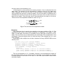
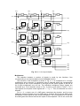
these signals. Fig. 1 depicts the circuit that DRUID uses when it comes along a D flipflop with set and reset and Fig. 2 shows the corresponding circuit for a D flip-flop that
besides these two abilities it can register a new input if only it is enabled by a certain
bit.
Each of these capabilities is using a separate signal and all three signals are
synchronized with the clock signal. When the set signal is set to ‘1’ the output of the
flip-flop is also set to ‘1’ (in the next clock cycle). Similarly, when the reset signal is set
to ‘1’ the output of the flip-flop is set to ‘0’. The third signal (en) when is set to ‘1’ allows
the flip-flop to register a new value if and only if the set and reset signals are set both to
‘0’. If en is set to ‘0’ then the output of the D flip-flop reappears in its input through the
input 0 of the multiplexer.
input
D
Q
output
reset
set
input
D
Q
output
clock
reset
set
clk
clock
Fig. 1 The circuit used to replace a D-f/f with set and reset and its equivalent block
input
D
Q
output
ce
reset
set
clock
input
ce
reset
set
D
Q
output
clk
clock
Fig. 2 The circuit used to replace a D-f/f with set, reset and enable, and its equivalent block
Synthesizers like Leonardo Spectrum that do not have simple flip-flops use D flipflops with set and reset instead which are deactivated when they are not needed.
DRUID gives the choice to the designer to decide if there simple D flip-flops (with no
set/reset inputs, available in PRIMLIB) will be used, or the equivalent circuits that were
described previously.
Logic gates of more than two inputs
DRUID searches a certain library declaration in the EDIF file (i.e. library
OPERATORS of the EDIF file that Leonardo Spectrum gives) for certain cells. These
cells, as it was explained before, declare only their name, their function, their
wordlength and their ports. Therefore, each time that DRUID comes across a different
cell in this library, it collects this information and activates a certain algorithm in order to
generate and add the architecture of this cell (in EDIF format) to the output EDIF file in
library USER_LIB. For each of the algorithms that are used to generate the cells that
DRUID finds in the library OPERATORS declaration of the input EDIF file, their
dependence on the wordlength of the required cell will be underlined.
In all the cells that are presented to unsigned arithmetic is assumed. In the case of
signed numbers DRUID’s operation would be more or less the same.
An example of the procedure described above is:
(cell or_5u_5u (cellType GENERIC)
(property (rename a120 "$GENERIC") (string "or"))
(property (rename a121 "$size") (string "5"))
(property (rename a122 "$signed") (string "false"))
(view INTERFACE (viewType NETLIST)
(interface
(port (array (rename a "a<4:0>") 5 )(direction INPUT))
(port d (direction OUTPUT)))))
The cells of this type describe gates of more than two inputs. This example refers to
an OR gate (property (rename a120 "$GENERIC") (string "or")), named or_5u_5u,
of five inputs (property (rename a121 "$size") (string "5")), and for unsigned signals
(property (rename a122 "$signed") (string "false")). For the rest of the gates this
form is exactly the same.
After the detection of the function of the cell, DRUID has to erase this cell from the
library and add the equivalent structure to library USER_LIB of the EDIF file. The
structure that has to be added in the case of the OR gate of multiple inputs is very
simple. For an OR gate of two inputs it uses a simple OR gate and for every other input
DRUID uses one more OR gate, which has as inputs, the output of the previous OR
gate and the extra input that is added. Except from this structure, the OR component
has to be included in library PRIMLIB in order to be declared its use.
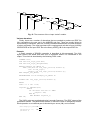
Fig. 3 pictures an OR gate of five inputs and its equivalent circuit. The first two
inputs are connected to the first OR gate, the third input to the second OR gate etc. If
an AND or a XOR gate of multiple inputs is needed the process will be exactly the
same with the exception that an AND and an XOR gate will be used respectively.
input0
input1
output
input2
input3
input4
input0
input1
input2
input3
input4
output
Fig. 3: An OR gate of five inputs and the equivalent gate symbol
Similarly the NAND, NOR and XNOR gates are substituted by exactly the same
method by AND, OR and XOR gates with the exception that their outputs are
connected to an inverter.
Magnitude comparators
In this task the procedure that is followed is exactly the same as previously. The
cells under search have more or less the same function. They compare the values of
two signals in order to determine either the equality or inequality between them, or
which of them is greater. The type of cell that DRUID searches for, in the library
OPERATORS declaration, is the following:
(cell eq_4u_4u (cellType GENERIC)
(property (rename a12 "$GENERIC") (string "eq"))
(property (rename a13 "$size") (string "4"))
(property (rename a14 "$signed") (string "false"))
(view INTERFACE (viewType NETLIST)
(interface
(port (array (rename a "a(3:0)") 4 )(direction INPUT))
(port (array (rename b "b(3:0)") 4 )(direction INPUT))
(port d (direction OUTPUT)))))
The cell that in this EDIF code detects the equality (property (rename a12
"$GENERIC") (string "eq")) between two (a(3:0), b(3:0)) of two unsigned numbers
(property (rename a14 "$signed") (string "false")) of wordlength 4 (property
(rename a13 "$size") (string "4")). If it was needed to check their inequality the
properties of the cell would have as “string” the initials “ne”. Also the initials “gt” would
appear for checking if b is greater than a and the “ge” when b is greater or equal to a.
When b is less than a or b is less or equal to a then the initials “lt” and “le” must be
used.
First we must describe the algorithm for the cell that checks the equality of a and b.
It is based on a simple logical equation: d = NOT ( x1 + x 2 ... + x n ) (1), where xi = (ai ⊕ bi ) ,
i = 1,2,..., n , n = the wordlength of a and b. It is obvious that an XOR gate is used for
each bit of a and b. If the two signal vectors have at least one signal with different
value, the corresponding XOR gate will output a high value. High value is the control
value of an OR gate and therefore an equality will invert that high value to low value.
So, output d will take a high value if and only if ALL the corresponding signals will have
the same values.
Fig. 4 shows the circuit that performs the equality comparison between two signal
vectors of wordlength 5. Each time that the wordlength of the input signal vectors is
increased, another OR and XOR gates are added to the structure. The same circuit is
used for the inequality except that the output of the OR gates is not inverted.
a(1)
b(1)
a(2)
b(2)
a(3)
b(3)
a(4)
b(4)
a(5)
b(5)
d
Fig. 4: Equality check between two signal vectors of wordlength 5
The algorithm for the cell that checks if the value of b is less or equal to a (b ≤ a) is
based on a simple logical equation:
d = a n • bn' + y n • (a n −1 • bn' −1 ) + ... + ( y n • y n −1 ... • y1 ) • (a1 • b1' ) + ( y n • y n −1 ... • y1 ) (2),
where y i = NOT (a i ⊕ bi ) , i = 1,2,..., n , n = the wordlength of a and b.
Fig. 5 shows the circuit that checks if the value of signal vector b is less than or
equal to the value of a and if one of the two conditions is true it sets its output to high
value.
a(1)
b(1)
a(2)
b(2)
a(3)
b(3)
y1
e
e
y 4 • y 3 • y 2 • y1
y2
e
e
d
y3
y4
a(4)
b(4)
y4 • y3
y4 • y3 • y2
a(1) • b(1) ' • ( y 4 • y 3 • y 2 )
a(1) • b(1) '
a ( 2 ) • b( 2 ) '
a ( 3 ) • b( 3 ) '
a(3 ) • b(3 ) ' • y 4
a( 4 ) • b( 4 ) '
Fig. 5: The circuit that checks the condition b ≤ a
The same procedure is taking place when the condition b ≥ a must be used. The
only difference is that input a will take the place of input b. When the equality in both
conditions is not needed then the last operand of equation (2) will not be used. The
circuit of figure 5 is the same in this occasion with only difference. The gates in figure 5
marked with letter “e”, are not used.
Adders, subtracters and incrementers
This task searches for cells of similar operation. An adder, a subtracter, a module
that performs both operations, an incrementer by one and a decrementer by one. All
these modules are based on a full-adder and a half-adder. The structures of the two
components are shown in Fig. 6 and Fig. 7 respectively. In this report both components
are represented by their equivalent block even though DRUID implements them with
the use of logic gates.
a
b
sum
a
b
cout
cin
sum
FA
cin
cout
Fig. 6: The structure of a full-adder and the equivalent block
a
sum
b
a
b
sum
HA
cout
cout
Fig. 7: The structure of a half-adder and the equivalent block
The adder that DRUID instantiates is a ripple-carry adder. It is formed by using a
full-adder for each signal of the signal vector. The subtractor is similarly generated by
using a ripple-carry adder. The operand that is going to be subtracted is in 2’s
complement representation. Thus the one input of each full-adder is inverted and the
cin input of the first full-adder is set to high value.
In order to combine these two operations in one module the architecture pictured of
Fig. 8 is used. The input signal mode controls the operation of this adder-subtracter
module. When set low the module performs an addition and when it is set high it
performs a subtraction. The wordlength of the signal vectors determine the number of
the full-adders and XOR gates that are required.
a(1) b(1)
a(2) b(2)
FA
a(n) b(n)
...
FA
mode
d(n)
FA
cout
d(1)
d(2)
Fig. 8: The structure of an adder-subtracter module
The incrementer is a circuit that adds ‘1’ to the value of the input. Its structure is
similar to a ripple-carry adder but instead of using full-adders it is created out of halfadders. One input of the half-adder is connected to the input of the incrementer and the
other is connected to the cout output of the previous half-adder. One input of the first
half-adder is connected to the cin signal of the incrementer and if that signal is set high,
the input value is incremented by one.
A decrementer by one performs the inverse procedure. One is subtracted from the
input value. The structure of the decrementer is similar to the one of a ripple-carry
adder. Although, the fact that one input of each full-adder is always assigned a high
value simplifies the structure of each full-adder. The first full-adder is substituted by a
half-adder that receives as input the first signal of the input vector and the inverted cin
signal of the module. Thus, the input value is decremented by one when cin is set low.
The structure of this simplified full-adder is shown in Fig. 9.
a
sum
b
cin
cout
Fig. 9: The structure of the simplified full-adder
Multipliers
The architecture that is used for the multiplier is the array multiplier of Fig. 10. This
architecture is an array of five kinds of elements: an AND gate, a full-adder, a halfadder, an AND gate connected to a half-adder and an AND gate connected to a fulladder. The size of the array is determined by the wordlength of the multiplicands. If the
wordlength of the input signal vector is n then the array of the multiplier has n +1 rows
and n columns.
In the case of the multiplier the cell that is declared in library OPERATORS has the
following form:
(cell mult_10u_10u_10u (cellType GENERIC)
(property (rename a0 "$GENERIC") (string "mult"))
(property (rename a1 "$size") (string "10"))
(property (rename a2 "$signed") (string "false"))
(view INTERFACE (viewType NETLIST)
(interface
(port (array (rename a "a(9:0)") 10 )(direction INPUT))
(port (array (rename b "b(9:0)") 10 )(direction INPUT))
(port (array (rename d "d(9:0)") 10 )(direction OUTPUT)))))
This cell corresponds to a 5 × 5 multiplier. However, in its declaration the signals of
the input signal vectors are ten instead of five. Practically, if five of them are unused,
Leonardo Spectrum sets them to low value. In the other hand DRUID erases these
redundant signals.
b(1)
b(2)
b(3)
b(4)
a(1)
d(1)
HA
HA
HA
a(1)
d(2)
FA
FA
FA
a(1)
d(3)
FA
FA
FA
a(1)
d(4)
HA
FA
FA
d(5)
d(6)
d(7)
d(8)
Fig. 10: A 4 × 4 array multiplier
Multiplexers
The selection between a number of signals is made by two functions. One
corresponding to a n-input multiplexer and the select function.
The structure of the multiplexer is shown in Fig. 11. It is comprised of n-1 2-input
multiplexers and a decoder. A multiplexer input is selected when the corresponding
select signal of the 2-input multiplexer is set high and the select signals of the rest of
the 2-input multiplexers are set low. The individual multiplexer select signals are
controlled by a 3-to-8 decoder shown in Fig. 12 and its truth table in Table 1. For n
input signals, the required control signals are w = ⎡log 2 n ⎤ . Thus, the decoder is a w-to-n
decoder.
For w = 2, a single row of n AND gates comprises the decoder, and for every
additional select bit another row of n AND gates is required. Each last row AND output
constitutes a select signal for each 2-input multiplexer. The only exception is for the two
first AND gates that control the first two inputs of the multiplexer. This is due to the fact
that both them two use the same 2-input multiplexer. That is why it is used an AND
gate more and the inverter.
The cell that declares the multiplexer in the input EDIF file includes the declaration
of two input ports (a and b). Both are signal vectors of wordlenth n. However, as shown
above, only w signals of the input port b are actually used. Therefore, DRUID erases
the rest of the signals that are redundant to multiplexer logic when producing the output
EDIF file, instead of connecting them to ground as Leonardo does.
in0
2-input
multiplexer
in1
a(1)
a(2)
select
...
a(3)
...
out
a(n-1)
d
a(n)
x(1)
...
x(2)
...
x(n-2)
x(n-1)
b(1)
DECODER
b(w)
Fig. 11: A n-input multiplexer
b(3) b(2) b(1) x(1) x(2) X(3) x(4) x(5) X(6) x(7) x(8)
0
0
0
1
0
0
0
0
0
0
0
0
0
1
0
1
0
0
0
0
0
0
0
1
0
0
0
1
0
0
0
0
0
0
1
1
0
0
0
1
0
0
0
0
1
0
0
0
0
0
0
1
0
0
0
1
0
1
0
0
0
0
0
1
0
0
1
1
0
0
0
0
0
0
0
1
0
1
1
1
0
0
0
0
0
0
0
1
Table 1: The truth table of the 3-to-8 decoder
x(1)
x(2)
b(1)
x(3)
b(2)
x(4)
b(3)
x(5)
x(6)
x(7)
Fig. 12: The structure of a 3-to88 decoder
The operation of the select function is described by the truth table of Table 2. The
output of “select” cell is the b(i) input when the a(i) input is set low and all other a inputs
are set low. This module can be easily constructed by AND and OR gates as shown in
Fig. 13.
a(n)
1
0
0
0
0
0
0
a(n-11)
0
1
0
0
0
0
0
…
0
0
1
0
0
0
0
a(i)
0
0
0
1
0
0
0
…
0
0
0
0
1
0
0
a(2) a(1)
0
0
0
0
0
0
0
0
0
0
1
0
0
1
d
b(n)
b(n-1)
…
b(i)
…
b(2)
b(1)
Table 2: The truth table of the n-input “select” module
b(1)
b(2)
...
b(3)
...
b(n-3)
b(n-1)
d
b(n)
a(1)
a(2)
a(3)
a(n-3)
a(n-1)
a(n)
Fig. 13: The structure of the n-input “select” module
Various alterations
Finally, there are a number of alterations that are needed to produce an EDIF file
fully compatible to the next tool in the AMDREL tool flow. These are mostly limited to
the renaming of instances, ports etc, erasing unneeded declarations and other changes
of minor complexity. The most important one is copying each cell that is found in library
OPERATORS of the input EDIF file to the library USER_LIB of the output EDIF file.
Example
A small example of DRUID’s operation is described in this paragraph. Two 2-bit
signal vectors are added and their sum is registered before it is connected to the
output. This circuit is described by the following VHDL code:
LIBRARY ieee;
USE ieee.std_logic_1164.ALL;
USE ieee.std_logic_unsigned.ALL;
ENTITY example_for_DRUID IS
PORT( in0,in1: in std_logic_vector(1 downto 0);
clk: in std_logic;
output: out std_logic_vector(2 downto 0));
END example_for_DRUID;
ARCHITECTURE rtl OF example_for_DRUID IS
SIGNAL sum: std_logic_vector(2 downto 0);
BEGIN
sum<= '0' & in0 + in1;
register_1: PROCESS(clk)
BEGIN
IF clk'event and clk='1' THEN
output<= sum;
END IF;
END PROCESS register_1;
END rtl;
The VHDL code was synthesized using Leonardo Spectrum. The EDIF output of the
synthesizer follows. The parts/words that are in italics are used or changed by DRUID.
Each operation to an italicized part is denoted by an arrow ( Î ) and a number.
(edif example_for_DRUID Í (1a)
(edifVersion 2 0 0)
(edifLevel 0)
Í (2)
(keywordMap (keywordLevel 0))
(status
(written
(timestamp 2004 02 07 19 12 33)
(program "LeonardoSpectrum Level 3" (version "v2001_1d.45"))
(author "Exemplar Logic Inc")))
(external PRIMITIVES
Í (1b)
(edifLevel 0)
(technology (numberDefinition ))
(cell FALSE (cellType GENERIC)
(view INTERFACE (viewType NETLIST)
(interface
(port out (direction OUTPUT)))))
(cell DFFRS (cellType GENERIC)
Í (3)
(view INTERFACE (viewType NETLIST)
(interface
(port set (direction INPUT))
(port reset (direction INPUT))
(port in (direction INPUT))
(port clk (direction INPUT))
(port out (direction OUTPUT)))))
)
(library OPERATORS Í (4)
(edifLevel 0)
(technology (numberDefinition ))
(cell add_2u_2u_2u_0 (cellType GENERIC)
Í (5a)
(property (rename a0 "$GENERIC") (string "add")) Í (5b)
(property (rename a1 "$size") (string "2"))
Í (5c)
(property (rename a2 "$signed") (string "false")) Í (5d)
(view INTERFACE (viewType NETLIST)
(interface
(port cin (direction INPUT))
(port (array (rename a "a(1:0)") 2 )(direction INPUT))
(port (array (rename b "b(1:0)") 2 )(direction INPUT))
(port (array (rename d "d(1:0)") 2 )(direction OUTPUT))
(port cout (direction OUTPUT))))))
(library work
Í (1c)
(edifLevel 0)
(technology (numberDefinition ))
Í (6)
(cell example_for_DRUID (cellType GENERIC) Í (1d)
(view rtl (viewType NETLIST)
Í (1e)
(interface
(port (array (rename in0 "in0(1:0)") 2 )(direction INPUT)) Í (7a)
(port (array (rename in1 "in1(1:0)") 2 )(direction INPUT)) Í (7b)
(port clk (direction INPUT))
(port (array (rename output "output(2:0)") 3 )(direction OUTPUT)) Í (7c)
)
(contents
Í (8)
(instance ix1 (viewRef INTERFACE (cellRef FALSE (libraryRef PRIMITIVES ))))
(instance (rename i0 "reg_output(2)") (viewRef INTERFACE
(cellRef DFFRS
(libraryRef PRIMITIVES ))))
(instance (rename i1 "reg_output(1)") (viewRef INTERFACE
(cellRef DFFRS
(libraryRef PRIMITIVES ))))
(instance (rename i2 "reg_output(0)") (viewRef INTERFACE
(cellRef DFFRS
(libraryRef PRIMITIVES ))))
(instance modgen_add_0 (viewRef INTERFACE
(cellRef add_2u_2u_2u_0 (libraryRef
OPERATORS ))))
Í (9)
(net (rename n0 "in0(1)")
(joined
(portRef (member in0 0))
(portRef (member a 0)(instanceRef modgen_add_0 ))))
(net (rename n1 "in0(0)")
(joined
(portRef (member in0 1))
(portRef (member a 1)(instanceRef modgen_add_0 ))))
(net (rename n2 "in1(1)")
(joined
(portRef (member in1 0))
(portRef (member b 0)(instanceRef modgen_add_0 ))))
(net (rename n3 "in1(0)")
(joined
(portRef (member in1 1))
(portRef (member b 1)(instanceRef modgen_add_0 ))))
(net clk
(joined
(portRef clk )
(portRef clk (instanceRef i0 ))
(portRef clk (instanceRef i1 ))
(portRef clk (instanceRef i2 ))))
(net (rename n4 "output(2)")
(joined
(portRef (member output 0))
(portRef out (instanceRef i0 ))))
(net (rename n5 "output(1)")
(joined
(portRef (member output 1))
(portRef out (instanceRef i1 ))))
(net (rename n6 "output(0)")
(joined
(portRef (member output 2))
(portRef out (instanceRef i2 ))))
(net (rename n7 "sum(1)")
(joined
(portRef (member d 0)(instanceRef modgen_add_0 ))
(portRef in (instanceRef i1 ))))
(net (rename n8 "sum(0)")
(joined
(portRef (member d 1)(instanceRef modgen_add_0 ))
(portRef in (instanceRef i2 ))))
(net GND
(joined
(portRef out (instanceRef ix1 )) Í (10)
(portRef set (instanceRef i0 ))
(portRef reset (instanceRef i0 ))
(portRef set (instanceRef i1 ))
(portRef reset (instanceRef i1 ))
(portRef set (instanceRef i2 ))
(portRef reset (instanceRef i2 ))
(portRef cin (instanceRef modgen_add_0 ))))
(net (rename n9 "sum(2)")
(joined
(portRef cout (instanceRef modgen_add_0 ))
(portRef in (instanceRef i0 ))))))))
(design example_for_DRUID (cellRef example_for_DRUID (libraryRef work )))) Í(11)
Arrows (1a, 1b, 1c, 1d and 1e) show the appropriate changes in the italicized names
that are going to be made according to the cell and library naming described above.
The signal vector changes are performed to 7a, 7b and 7c that indicate which signal
arrays are unfolded to simple signals and 9 shows the point where renaming will take
place and are going to be changed the signals whose name appears after the word
“member”. Function “rename” will also partially affect 7a, 7b, 7c and 8.
Once cell DFFRS (3) is found after the declaration of library PRIMITIVES (1b),
DRUID can either add at (6) the equivalent circuit named “DFF_SETRESET” or remove
the set and reset signals. In either case cell DFFRS at (3) will be replaced by cell DFF.
In this case, the second choice is preferable because these two signals are
deactivated. Thus, they are erased from the cell GND at (10). It must be noted that
because the substitution of cell DFFRS by cell DFF will also happen at (8).
Once DRUID comes across library OPERATORS (point 4) the cell which is named
“add_2u_2u_2u_0” (at point 5a), it becomes evident from (5b) that this cell describes
an adder of two 2-bit signals (5c) that represent unsigned numbers (5d). Then in
position (6) DRUID is going to add the architecture of an adder named “adder_gen_2”.
The name “add_2u_2u_2u_0” will be substituted by the name of the new cell (8).
The signature of the input EDIF file (2) is also altered, and the last line of the file
deleted (11).
The output EDIF file is shown below. The changed parts are in italics and the arrows
are still in place in order to facilitate the comparison of the two EDIF files. The only
remark is that three more cells are added to library PRIMLIB (1b) because cell
“adder_gen_2” is used.
(edif netlist
Í (1a)
(edifVersion 2 0 0) Í (2)
(edifLevel 0)
(keywordMap (keywordLevel 0))
(status
(written
(timeStamp 1977 07 12 00 15 00)
(program" DRUID - DemocRitus University edIf to eDif converter" (version"
v2.1"))
(author" VLSI Design and Testing Laboratory - Democritus University of Thrace HELLAS")))
(external PRIMLIB Í (1b)
(edifLevel 0)
(technology (numberDefinition))
(cell XOR3 (cellType GENERIC)
(view INTERFACE (viewType NETLIST)
(interface
(port out (direction OUTPUT))
(port in2 (direction INPUT))
(port in1 (direction INPUT))
(port in0 (direction INPUT)))))
(cell AND2 (cellType GENERIC)
(view INTERFACE (viewType NETLIST)
(interface
(port in0 (direction INPUT))
(port in1 (direction INPUT))
(port out (direction OUTPUT)))))
(cell OR3 (cellType GENERIC)
(view INTERFACE (viewType NETLIST)
(interface
(port out (direction OUTPUT))
(port in2 (direction INPUT))
(port in1 (direction INPUT))
(port in0 (direction INPUT)))))
(cell FALSE (cellType GENERIC)
(view INTERFACE (viewType NETLIST)
(interface
(port out (direction OUTPUT)))))
(cell DFF (cellType GENERIC) Í (3)
(view INTERFACE (viewType NETLIST)
(interface
(port in (direction INPUT))
(port clk (direction INPUT))
(port out (direction OUTPUT)))))
)
(library OPERATORS Í (4)
(edifLevel 0)
(technology (numberDefinition))
)
(library USER_LIB Í (1c)
(edifLevel 0)
(technology
(numberDefinition)
(simulationInfo
(logicValue H (booleanMap (true)))
(logicValue L (booleanMap (false)))))
Í (6)
(cell adder_gen_2 (cellType GENERIC)
(view rtl_adder (viewType NETLIST)
(interface
(port cin (direction INPUT))
(port a_0 (direction INPUT))
(port a_1 (direction INPUT))
(port b_0 (direction INPUT))
(port b_1 (direction INPUT))
(port d_0 (direction OUTPUT))
(port d_1 (direction OUTPUT))
(port cout (direction OUTPUT)))
(contents
(instance
and2_0_adder_2_1
(viewRef
INTERFACE
PRIMLIB))))
(instance
and2_0_adder_2_2
(viewRef
INTERFACE
PRIMLIB))))
(instance
and2_0_adder_2_3
(viewRef
INTERFACE
PRIMLIB))))
(instance or3_0_adder_2 (viewRef INTERFACE (cellRef
(instance
xor3_0_adder_2
(viewRef
INTERFACE
PRIMLIB))))
(instance
and2_1_adder_2_1
(viewRef
INTERFACE
PRIMLIB))))
(instance
and2_1_adder_2_2
(viewRef
INTERFACE
PRIMLIB))))
(instance
and2_1_adder_2_3
(viewRef
INTERFACE
PRIMLIB))))
(instance or3_1_adder_2 (viewRef INTERFACE (cellRef
(instance
xor3_1_adder_2
(viewRef
INTERFACE
PRIMLIB))))
(net cin_adder_gen_2
(joined
(portRef cin)
(portRef in1 (instanceRef and2_0_adder_2_2))
(portRef in1 (instanceRef and2_0_adder_2_3))
(portRef in2 (instanceRef xor3_0_adder_2))))
(net a_0_adder_gen_2
(joined
(portRef a_1)
(portRef in0 (instanceRef and2_0_adder_2_1))
(portRef in0 (instanceRef and2_0_adder_2_2))
(portRef in0 (instanceRef xor3_0_adder_2))))
(net a_1_adder_gen_2
(joined
(portRef a_0)
(portRef in0 (instanceRef and2_1_adder_2_1))
(portRef in0 (instanceRef and2_1_adder_2_2))
(portRef in0 (instanceRef xor3_1_adder_2))))
(net b_0_adder_gen_2
(joined
(portRef b_1)
(portRef in1 (instanceRef and2_0_adder_2_1))
(portRef in0 (instanceRef and2_0_adder_2_3))
(portRef in1 (instanceRef xor3_0_adder_2))))
(net b_1_adder_gen_2
(joined
(portRef b_0)
(portRef in1 (instanceRef and2_1_adder_2_1))
(portRef in0 (instanceRef and2_1_adder_2_3))
(portRef in1 (instanceRef xor3_1_adder_2))))
(net d_0_adder_gen_2
(joined
(portRef d_1)
(portRef out (instanceRef xor3_0_adder_2))))
(net d_1_adder_gen_2
(joined
(portRef d_0)
(portRef out (instanceRef xor3_1_adder_2))))
(net intern_a0_adder_gen_2
(joined
(portRef out (instanceRef and2_0_adder_2_1))
(portRef in0 (instanceRef or3_0_adder_2))))
(net intern_b0_adder_gen_2
(joined
(portRef out (instanceRef and2_0_adder_2_2))
(portRef in1 (instanceRef or3_0_adder_2))))
(net intern_c0_adder_gen_2
(joined
(cellRef
AND2
(libraryRef
(cellRef
AND2
(libraryRef
(cellRef
AND2
(libraryRef
OR3 (libraryRef PRIMLIB))))
(cellRef
XOR3
(libraryRef
(cellRef
AND2
(libraryRef
(cellRef
AND2
(libraryRef
(cellRef
AND2
(libraryRef
OR3 (libraryRef PRIMLIB))))
(cellRef
XOR3
(libraryRef
(portRef out (instanceRef and2_0_adder_2_3))
(portRef in2 (instanceRef or3_0_adder_2))))
(net intern_a1_adder_gen_2
(joined
(portRef out (instanceRef and2_1_adder_2_1))
(portRef in0 (instanceRef or3_1_adder_2))))
(net intern_b1_adder_gen_2
(joined
(portRef out (instanceRef and2_1_adder_2_2))
(portRef in1 (instanceRef or3_1_adder_2))))
(net intern_c1_adder_gen_2
(joined
(portRef out (instanceRef and2_1_adder_2_3))
(portRef in2 (instanceRef or3_1_adder_2))))
(net intern_carry_0_adder_gen_2
(joined
(portRef out (instanceRef or3_0_adder_2))
(portRef in1 (instanceRef and2_1_adder_2_2))
(portRef in1 (instanceRef and2_1_adder_2_3))
(portRef in2 (instanceRef xor3_1_adder_2))))
(net cout_adder_gen_2
(joined
(portRef cout)
(portRef out (instanceRef or3_1_adder_2)))))))
(cell TOP (cellType GENERIC)
Í (1d)
(view netlist (viewType NETLIST) Í (1e)
(interface
(port in0_0 (direction INPUT)) Í (7a)
(port in0_1 (direction INPUT))
(port in1_0 (direction INPUT))
Í (b)
(port in1_1 (direction INPUT))
(port clk (direction INPUT))
(port output_0 (direction OUTPUT)) Í (7c)
(port output_1 (direction OUTPUT))
(port output_2 (direction OUTPUT))
)
(contents
(instance
(instance
(instance
(instance
(instance
USER_LIB))))
Í (8)
ix1 (viewRef INTERFACE (cellRef FALSE (libraryRef PRIMLIB))))
i0 (viewRef INTERFACE (cellRef DFF (libraryRef PRIMLIB))))
i1 (viewRef INTERFACE (cellRef DFF (libraryRef PRIMLIB))))
i2 (viewRef INTERFACE (cellRef DFF (libraryRef PRIMLIB))))
modgen_add_0 (viewRef rtl_adder (cellRef adder_gen_2 (libraryRef
Í (9)
(net n0
(joined
(portRef in0_0)
(portRef a_0 (instanceRef modgen_add_0))))
(net n1
(joined
(portRef in0_1)
(portRef a_1 (instanceRef modgen_add_0))))
(net n2
(joined
(portRef in1_0)
(portRef b_0 (instanceRef modgen_add_0))))
(net n3
(joined
(portRef in1_1)
(portRef b_1 (instanceRef modgen_add_0))))
(net clk
(joined
(portRef clk)
(portRef clk (instanceRef i0))
(portRef clk (instanceRef i1))
(portRef clk (instanceRef i2))))
(net n4
(joined
(portRef output_0)
(portRef out (instanceRef i0))))
(net n5
(joined
(portRef
(portRef
(net n6
(joined
(portRef
(portRef
(net n7
(joined
(portRef
(portRef
(net n8
(joined
(portRef
(portRef
(net GND
(joined
(portRef
(portRef
(net n9
(joined
(portRef
(portRef
output_1)
out (instanceRef i1))))
output_2)
out (instanceRef i2))))
d_0 (instanceRef modgen_add_0))
in (instanceRef i1))))
d_1 (instanceRef modgen_add_0))
in (instanceRef i2))))
out (instanceRef ix1)) Í (10)
cin (instanceRef modgen_add_0))))
cout (instanceRef modgen_add_0))
in (instanceRef i0))))))))
Í (11)
Future work
Alternative modules can be used for substituting the adder cell that is instantiated in
the input EDIF file such as carry-lookahead adders. Additionally, DRUID can be
modified to support EDIF files created by other synthesis tools.
INPUT
OUTPUT
LIMITATIONS
EDIF format generic netlist (LEONARDO type)
EDIF format generic netlist (E2FMT compatible)
Other generic EDIF format netlists not currently
supported