1
RT-210
(Formerly STARTOS)
User’s Manual
May 5, 2015
© Anatoly Besplemennov
Introduction
The system may be ported and adapted on any ARM platform. Previous realization was
for ARM9 and Mini2440 board and is known as StartOS (The StartOS name was registered by
Russia PO 19 Aug 2011). Here the version for ARM Cortex-A8 will be considered. It intended
for the Samsung S5PV210 SoC and the FriendlyARM's Mini210s board.
The FriendlyARM's boar “Mini210s” attracts users by it’s’ possibilities and low cost.
Mini210s is useful for developing industrial automation systems.
Many specialists try to carry the properties of mainframe computers to the Friendly ARM.
But there is also another approach, from simple to complex i.e. from rapidly developing MCUs.
Computer market offers desktop computers, notebooks, Net books, tablets. At the
present time in industrial automation field the Mini2440 and Mini210s board has fewer number
of competitors, taking in consideration the set of external devices mounted aboard, jacks for
their connection and wide range of LCD screens.
Many users successfully working with traditional computers and microcontrollers meet
difficulties developing and applying ARM systems.
All that impelled the author to create not complex system for industrial automation,
laboratory purposes and as an instrumental aid for scientific experiments. STARTOS was
created by engineer and for engineers.
A system aimed to contain functions, which we like to use: simplicity, reliability,
launching programs from external drives, providing the user with the system functions through
the mechanism of program interrupts. The system does not limit the user possibilities but gives
him the services. It executes all duty work allowing the user to think about his main task.
It was built to be clear, easy to use, quick for learning and applying by engineers,
students and specialists in other non-programming fields.
Functions and developing process are widely illustrated with working tested examples.
Quick start
In order to briefly verifying system abilities, not in details, it’s necessary to do the
following:
First, please watch a short video about it: https://youtu.be/z9cYu7sYwV0
Go to Download page http://physicalcomputing.ru/articles_en/p_rt-210_en.html
–
Download SD-Flasher utility, FriendlyARM's Superboot binary file, SD Card .RAR
Archive;
–
Prepare a SD card (it may be SDSC or SDHC) using SD-Flash Utility;
–
Write the folder “images”, binary example files and .BMP file onto SD Card Root;
–
Put the SD Card in the Mini210s slot, move switch to SD boot position;
–
Turn the power switch On.
First time System will ask to calibrate the touch screen.
Press [ > ] in the left lower corner of the screen. List of files from SD card will appear.
Next, click on the file name with the stylus, for example, tap Hello1.BIN. It must begin to
work.
System properties
The system is written using C and Assembler languages. Actually it is the kernel with the
User interface and minimal set of necessary functions. That is why it had no beautiful
appearance with clock and calendar. (This may be done by making file Start.bin - it will be
playing the Shell's role. For industrial purposes it’s not needed).
Start time after power on:
about 1 s
Size of program:
less than 33 KBytes
SDRAM loading address:
0x3F500000.
System occupies a small volume in the upper SDRAM area providing the user’s standard
programs loading from address 0x20000000 (very beginning of the RAM) and memory volume
of 0x3F500000-0x20000000= 525336576 Bytes (almost all 512 MB).
Autorun User’s program after power on
presents
If the file named START.BIN is present on the SD card, it will be launched automatically.
The user is granted to have full control over hardware resources.
System functions
- Initialization the SoC (system on chip) Samsung S5PV210 external devices;
- User programs loading and inter-working with system functions;
-
Working with the LCD in text and graphic modes ( output Text, Pixels, Lines, Boxes, BMP
pictures, Saving / Restoring Screen areas );
-
Reading pen X, Y coordinates of the touch screen;
-
Working with the RTC (real time clock);
-
Reading data from analog to digital converters (ADC);
-
Reading / Writing Data to / from digital ports;
-
Reading / Writing Bytes and Strings of the COM Port;
- Working with pulse-width modulators (PWM) and Piezo buzzer, Sound output 8 bits per
sample 16KHz sample rate is supported as well;
- Reading/writing files from/to the SD card.
Networking (Receive/Transmit Ethernet packets, TCP IP Web Client/Server) as was in
StartOS did not implemented yet, may be done if there will be the Users interest.
Screen calibration data are stored in EEPROM.
Work with SD cards is very useful for embedded systems for changing and upgrading
programs. It also preserves the NAND Flash memory with limited write cycles and soldered into
the system board.
System was tested and verified on SDSC and SDHC cards with the FAT32 file system.
Card’s Class (data transfer speed) determines the loading time.
The system is using the Interrupts Driven model. The user must avoid implementing
system’s software interrupts in Interrupt Service Routines (ISR). The ISRs must be short and
work with Hardware resources only and set Flags for Main Program. However, it can be
changed. Doing this, the System must understand from which Processor Mode it came into the
Interrupt and set the Processor Mode in proper status. It may be done automatically.
Also, the system can be forced to execute Data arrays as instructions. It is useful for
experimenting with Evolutionary Algorithms (Genetic Algorithms in particular), for creating the
self-modified Program Code.
Programmer’s interface
Function description
The system is on developing with adding new functions.
Exit (void);
Exit the user's program.
Delay (int ms);
Delay_uS(int uS);
Delays execution of the program. Parameters : number of milliseconds or uSeconds
Screen operations
Fill_Screen (int color);
Fill screen by the color. Parameter: color (depth 16 bits per pixel)
Text
Set_Font (char Bold, int Fore_Col, int Back_Col);
Changes the current font. Parameters: 1st: 1-bold, 0- normal; 2nd: color of symbols, 3rd:
color of the background, (if equal 1, background will be transparent).
Print_String (int x0, int y0, char *txt);
Outputs the String of text to the LCD. Parameters: 1st and 2nd - abscissa and ordinate
of the line beginning position in pixels, 3rd: pointer to text buffer or the line itself in quotationmarks.
Examples:
char txt [ 5 ] = { "Hello" };
// or char *txt=”Hello”
Print_String ( 30, 50, txt );
Print_String ( 30, 70, "Hello, World!" );
The text is printed by previously defined font.
Printf (int x, int y, char *fmt,...);
Prints out the line of formatted text
Examples:
z=0xCDEF12;
Printf (80, 170, "Z=0x%x", z);
Graphics
Set_Color (int Color);
Establishes a current color for functions Put_Pixel, Line and painted rectangle (Box).
Put_Bmp (int x0, int y0, char *bmp );
Put out bitmap image on the LCD with the coordinates of the left upper corner x0 and y0.
3rd parameter points onto the image buffer with type “char”. First 4 bytes in the buffer must
represent: first pair - width of the image, second pair - height.
Example:
char run [ ] =
{ 32, 0, 6, 0,
// w = 0032, h = 0006
0xff, 0xf0, 0xff, 0xf0, 0xff, 0xf0, 0x00, 0x00, 0x54, 0x14, 0xff, 0xf0,0x00,
0x00, 0x54, 0x14, 0xff, 0xf0, 0x00, 0x00, 0xf……..}
Put_Bmp ( 198, 139, run );
Draws image with = 32 and height = 6 pixels in the screen area with the coordinates of
upper left corner x=198, y=139. Pixels of images are described in user char array run [ ].
Put_Pixel (int x, int y, int color);
Puts one dot pixel on the LCD with coordinates “x” and “y” and color “color”.
Get_Pixel (int x, int y);
The function returns color value of the screen point with coordinates x and y in user
variable, for example:
int
pix_color;
pix_color = Get_Pixel (60, 80);
Put_Line (int x0, int y0, int x1, int y1 );
Draws the line on the LCD which begins at x0 and y0 and ends at x1 and y1 coordinates.
Color is determined by last operator Set_Color.
Save_Box (int x0, int y0, int w, int h);
Stores rectangular area of the screen with coordinates of left upper corner x0 and y0,
width w and height h in system’s inner buffer.
Restore_Box (int x0, int y0 );
Restores the rectangular area onto the screen with the coordinates of the left upper
corner x0 and y0, with width w and height h which was stored in the system’s inner buffer.
Box (int x0, int y0, int x1, int y1 );
Draws rectangle on screen with coordinates x0, y0, x1, y1. The color of rectangle
monotonously subsides from value given by last operator Set_Color from top to bottom. May be
useful for drawing buttons, bars, etc.
LCD Control
TS ( char brit );
Set the screen back light LEDs brightness.
The parameter must be in 0...127 limits.
Example.
TS ( 120 );
- set LCD brightness as 120
Touch Screen
int
TS ( );
Returns the Stylus and X, Y state and values
Example: usage please see at examples
int
pen;
int
x,y;
pen = TS( 0x40 );
if
// Read Touch Screen Status, X, Y
( pen )
{
x = pen&0x3FF; y = ( pen>>10 );
// each 10 bit long
Printf ( 350, 20, "x = %4d", x ); Printf ( 350, 40, "y = %4d", y );
}
Real Time Clock (RTC)
Get_RTC (char *txt);
The function fills the txt char array by date and time in format: dd.mm.yy hh:mm.ss Then
the user program can change the order of digits if needed and use its’ values.
Timer
Get_ms ( );
Returns number of milliseconds have passed since the last system start. The Timer4 is
initialized and used as the system timer. Also it may be used for switching between tasks.
Example.
ms=Get_ms();
SD card
int
Read_SD
( char *RAM_address, U32 SD_address, U16 block);
int
Write_SD
( char *RAM_address, U32 SD_address, U16 block);
Direct reads/writes areas on the SD card.
Input: pointer to the buffer or physical address in RAM, SD card address, number of
blocks. One block equal 512 Bytes. Useful for custom file systems or fast transfer.
Files
int
Open_File (char *fname);
Opens the file with specified file name. Returns the length or 0 if file not exists.
F_Len = Open_File( snd_tst );
int
Read_File(char *f_buf, int len);
Reads len number of Bytes from the open file into the buffer or address.
Example.
int
F_Len;
char
SND_Buffer
[100000];
// Snd File_Buffer
char
PIC_Buffer
[260000];
// Pic File_Buffer
char
snd_tst[11]
= {'S','O','U','N','D','T','S','T','D','A','T'};
.
.
.
.
.
.
F_Len = Open_File( snd_tst );
Printf (0,50,"Sound File Len = %04d", F_Len );
Read_File (SND_Buffer, F_Len);
PSound ( SND_Buffer, F_Len );
int
Write_File (char *f_buf, int len);
Example.
char
txt1_tst[11]
= {'T','E','X','T', '_', 'I', 'N',' ','T','X','T'}; // put spaces when no letters
char
txt2_tst[11]
= {'T','E','X','T','_','O','U','T','T','X','T'};
F_Len = Open_File( txt2_tst );
//
open file for writing
Write_File ( W_Buff, F_Len );
//
write the data
Notes:
1. File for writing must be previously created on your PC and have sufficient size
2. The buffer for file’s data must be big enough to accept the data. It must be aligned by
the cluster size. For instance, you plan to write the BMP file for 240x320 and 24 bpp. It has size
230454 Bytes including the Head. So, the buffer will be at least 245760 Bytes. The number
245760 = 15 clusters x 16384 Bytes in one cluster. 16384 is the max cluster size for FAT32.
You may choose from 512 to 16384 while formatting the card. More the cluster size, more the
speed.
Simple method: just look at the file’s size on your PC and add some value.
Analog To Digital Donverter (ADC)
Get_ADC (char ADC_chan);
Returns measured voltage applied to the input pins of ADC (channels 0…5) into user
variable.
Example:
int
ADC_data;
ADC_data = Get_ADC( 0 );
Set_Font ( 1, Yellow, 20);
Printf ( 50, 70, "ADC Channel 0 = %03d", ADC_data );
Pulse width modulator (PWM) and Piezo Buzzer
PWM_out2
(U8 val);
//
this is the PIN28 at CON6
Outputs the pulse width modulated signal on corresponding pins. Val must be in 0…255
limits. Useful for analog output and the servo motor control.
Buzz (int freq, int ms);
Connects the on board Piezo buzzer to the first PWM channel output and the Buzzer
produces sound with frequency freq and duration ms.
Buzzer_Freq (int freq);
Defines the frequency produced by PWM in Hertz.
Buzzer_Out (char on_off);
Connects (if parameter=1) or disconnects (if parameter=0) PWM Out from Piezo Buzzer.
So it will produce sound or keep silence.
Sounds using PWM, Pezospeaker or Amplifier with Loudspeaker
void
PSound (U8 *buf, int len );
Plays Sound Data from buffer buf with length len.
The function uses the PWM Timer0 in Interrupts Mode. Immediately returns control to
the User program while keeping the sound playing.
Example:
PSound
( sound1, 5946 );
PSound
( sound1+offset, 5946-offset ); // Plays not from the beginning
Sound Data is prepared by Utility supplied. It must be 8-bits per sample, 16 kHz sample
rate.
You will hear sounds, produced by on board Piezospeaker.
Do append sequence …128,100,80,60,40,20 at the End of Sound array to avoid “click” if
needed.
Working with the IIC bus
U8
void
IIC_read
IIC_write
( U8 slave_addr, int addr);
( U8 slave_addr, int addr, U8 data);
The first reads and returns the byte of data from a device on the IIC bus with pointed
slave address and inner address in the device’s memory raw.
The second writes byte of data into the device.
Some devices support autoincrement of addresses. In such cases the pointer to raw
data must be used and the number of bytes to be transferred. It’s more complex to novices.
Interested users may order this method or develop their own.
The compass sketch shows how to work with EEPROM and accelerometer/compass
chip.
Universal asynchronous receiver-transmitter
( UART, COM Port )
Uart_Init (char chan, int BaudRate);
Initializes UART and assigns Data exchange speed.
Example:
Uart_Init ( 0 , 115200 );
Uart_Select (char chan);
- sets channel 0 and speed 115 KBod
Select one of three UART channels
Uart_Printf ( char *fmt, ... );
Sends a line of formatted text into a COM port.
Uart_TxEmpty (char chan);
Flushes the UART shift register data in the channel pointed. (Clears it and prepare to
work).
char
Uart_GetChar (char chan);
Gets UART data byte, stores it in User variable with waiting for the data's appearance.
char
Uart_GetKey (char chan);
Gets UART data byte, moves it in User variable without waiting of data get ready.
If the data in register exist, they will be read, if no, program continues its execution.
Uart_GetString (char *string);
Inputs line of symbols from the port until buffer of the line will ends or will be accepted
symbol \r (<lf>+<cr>, key [Enter]).
Uart_SendByte (char data);
Sends a byte of data into a COM port.
Uart_SendString (char *pt);
Sends a line of symbols into COM port. Parameter – pointer to line or line by itself closed
in quotation-marks.
Miscellaneous functions
Dec2Asc (int num, char *txt);
Translates decimal number num into char type and places it in txt array.
Hex2Asc (int num, char *txt);
Translates hexadecimal number num into char type and writes it into the txt array.
Network functions*
Networking is in StartOS, in RT-210 is not implemented yet, but may be done
Network interface controller initialization
char NIC_init (char *MAC_addr);
res = NIC_Init ( macaddr );
Initialize the NIC with the MAC address.
Returns error codes or the connection parameters (the speed, half/full duplex).
Packet receive
int NIC_rx (U16 *RX_buffer);
rx_len = NIC_rx( RX_data) );
Reads the Ethernet packet into the buffer, returns the length of the packet or zero.
Transmit packet
void NIC_tx (U16 *TX_buffer, U16 Nbytes);
NIC_tx ( TX_data, 70 );
Send the packet from buffer with length in Bytes.
The Web Server
Server ( 80, Mini210s_ip, page1, strbuf );
Input: the Port number, the source IP address, the buffer with Page.
Returns the String (up to 10 Bytes) which contains arguments got from the Browser to
perform analyze and processing.
The Client
res = Client ( Mini210s_ip, server_ip, request, buf );
Input: the source, destination IP addresses, request to Server.
Output: the pointer to buffer containing the Page received from the Server and
res=number of Bytes received.
More detailed Networking description see in Appendix 2.
Program examples
Please download Sketches Examples and write them into C:/Exam_210 folder, then go
inside some example folder and double click the .MCP file. Edit the Main.c file, press [F7] and
you will get .BIN file.
Some examples even does not need an assembler initialization file.
Projects were prepared in Metrowerks CodeWarrior for ARM Developer Suite v1.2. It is
assumed, that environment is installed on your computer. Also some projects were ported in
Keil uVision4 IDE and IAR.
There are enough only three files for a project:
- start.s
- system Initialization;
- StartOS.c
- description and system functions;
- Main.c
- your program itself
Size of executing binary module also depends from option “One ELF section per
function”. If it is checked, program size, for example, Hello1.bin decreases from 776 to 180
bytes. More complex programs in this case may not work, then simply cancel (uncheck) the
option.
You can also use standard init files from ADS, Keil or IAR.
For work with examples is necessary to do:
- Find and launch the file of project with .mcp extension, for example, Hello1.mср.
Edit file Main.с on your consideration, taste and style. Also you can edit the names of the
system calls in the file StartOS.с as you wish.
For build project Press [F7].
In folder C:\sketches\HELLO1\Hello1_Data\DebugRel_bin will appear file Hello1.bin.
Write Hello1.bin in root of SD card. Insert card in Friendly ARM, turn power on.
During 1 second will appear the system screen.
Press [ > ] in the left lower corner of the screen.
List of files on SD then will appear.
Tap Hello1.bin by Stylus.
The program must begin to work.
Next you can experiment with other programs.
In case of any questions, please contact author.
All educational projects were verified on operability. They can be used as base for
building your programs. Simply Edit text of Main.с, translate and get ready programs.
Folder Pictures contains primitives for examples STEPMOTOR and HELLO2.
In folder BMP2C you will find programs for converting BMP files onto source text in C
language. This utility is from DVD supplied with Friendly ARM.
The GLCD FontCreator and Evafont utilities let you make your own font.
The WaveEditor, AudioConverter, Converter WAV to C source are used for embedding
Sounds in your Projects.
Appendix 1
Getting started with the ADS1.2
Install the Metrowerks CodeWarrior for ARM Developer Suit v1.2
Copy the sketch which you plan to work with on C:\
For instance, it will be C:\STEPMOTOR
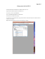
Go to C:\STEPMOTOR\StepMot.mcp and launch it
You’ll see Files, included in the project
First time files may be marked with [v] sign at the left side. It means that they were “touched” and are
needed to be compiled.
Right-Click on the filenames one by one and do perform “Compile”
Next, double click with the Left mouse key on the file you want to edit. For example, main.c
Rotate your monitor in the Portrait position if it’s possible.
Change the screen colors as you prefer.
Select your favorite font (I use Arial size 8 because I think that fonts such as Courier have additional
elements which can overload you visual sensors and the brain).
In the Control Panel->Screen-> ClearType try to unselect this option. The text on your screen must
become sharp with no “wool” borders.
Change the name of Binary file as you like:
Last, press [F7] to compile your project
In the Folder C:\STEPMOTOR\StepMot_Data\Binary you will find the binary file StepMot.bin.
Copy it onto an SD or MicroSD card, put in the FriendlyARM Mini210s board and use.
Note. All necessary options are already set for these example projects. For your new projects you can
just copy one of them onto another folder named by your project’s name. Rename the project file
with .MCP extension, add/remove sources and you are done.
P.S. It must be programs for Linux (Ubuntu) letting you to work with the Windows applications.
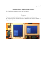
Appendix 2
Networking (Not for Mini210s, but for Mini2440)
The STARTOS has embedded Web Server and Client functions.
The Server
Connect the FriendlyARM Mini210s board to PC or to the Router via the Ethernet cable.
Put the server.bin or the client.bin files onto the SD/MicroSD card. They can be found in
Projects folders, Binary section.
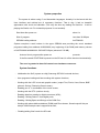
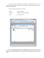
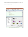
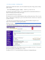
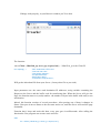
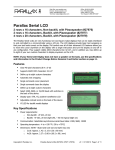
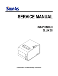
Launching the server.bin you can see it window in your favorite browser:
The Page strings of the source file may contain the Data of sensors attached to the board. You
can put there any items from Hardware/Software of your board.
U8 page1[] = "HTTP/1.0 200 OK\nContent-Type: text/html\n\n"
"<meta http-equiv=""refresh"" content=""1"">"
"<center><p><h1>The mini210s Web Server</h1></p> "
"<hr><br> <h2><font color=\"blue\">your board is connected to the World!"
"<br>now you can use the Internet of Things"
"<br>read the board's digital&analog sensors";
Also, you can put parameters to the board from the Browser line:
http://192.168.1.17/?parameter
String with parameters is up to 10 Symbols (may be increased). Depending of the Parameter or
its value you can control your board - turn something On/Off, playing sounds, etc.
Parameter (value) will be displayed on LCD after “?” sign.
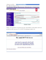
Pressing the [ Tap to play… ] buttons in the Browser window will force your Mini210s plaing
sounds.
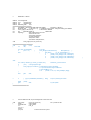
The source code
Board is initialized with addresses.
U8 macaddr[6] = {0xAA,0xAD,0xBE,0xEF,0xFE,0xED}; // Assign your MAC to your Board or left it
U8 Mini210s_ip[4] = {192,168,1,17};
// up to you (refer values)
res = NIC_Init ( macaddr ); // initializing the NIC
Main function includes Port number, source IP, destination IP, pointer to Page, pointer to String
buffer returned:
Server ( 80, Mini210s_ip, page1, strbuf ); // Mini210s_ip as the Server IP
The function returns Pointer to strbuf, so you can find parameters transmitted from Browser to
Board for analyzing and performing some actions.
It’s all for Mini210s-PC direct connection.
The internet service provider usually demands the Name and Password to log in. Thus, I use the
Router. Additionally to doing login, it gives me the Home Network. All devices are connected
by cable or wireless.
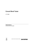
For outer access to your Board from any place try to find the IP address assigned to your
Router. Then in the Browser window type this address.
Sorry for non English letters. In my Netgear router the access address is 192.168.1.1 You can see
that my ISP assigned me an IP address 78.11.255.28.
An address 192.168.1.17 is used in the Sketch to initialize the FriendlyARM board.
To prevent attempts of dynamically addressing by the router, this address was reserved by me in
the router for the Arduino or Mini210s boards. Also it remembers the MAC address for filtering
aliens’ devices.
And last, some Switches/Routers don’t allow access from anybody. Then put an address
192.168.1.17 to enable outer connections. This will set the DMZ Server default address.
Finally, your board will be accessed from any place of the World by external address which was
given by your ISP (in my case 78.111.255.28). The default port number is 80.
The Client
To begin this work if you are a novice in this field, please perform some steps.
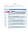
First, for experiments, I recommend you to download the Apache Web Server from their Site
(this procedure is quick and easy and it’s free).
Install it on your desktop PC for instance in C:\W folder.
Use the Server name as 192.168.1.5.
Configure your PC with an IP address 192.168.1.5 for example.
Sometimes other programs don’t let the Apache server to start. You can quit them and try again.
In my case I quitted the Skype. After launching Apache service I restarted Skype. On the next
System booting nothing needed to do. Both of them work fine.
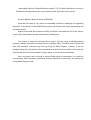
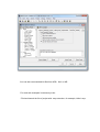
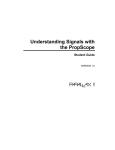
The file C:\W\htdocs\index.html is the file which will be accessed first (of course, you can get
other files).
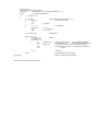
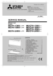
If things work properly, in your Browser window you’ll see that:
The function:
res = Client ( Mini210s_ip, server_ip, request, buf ); // Mini210s_ip is the Client IP
U8 request[] =
"GET /index.html HTTP/1.0\n"
"Host:192.168.1.5\n"
"User-Agent: startos\n"
"Accept: text/html\n"
"Keep-Alive: 300\n"
"Connection: keep-alive\n\n" ;
Will get the index.html file from your Server. (Or any other file as you wish).
Input parameters are: the source and destination IP addresses, string variable containing the
Request to the Server and the buffer used for transferring data. When the Server will give the
Page, the function return res (result) number –the number of bytes in the buffer with ready to use
information.
Indeed, this function consists of several procedures. After passing one of them it changes its
Status. Next pass it moves Status to the next state and so on, until the Server will send the page
demanded.
Function don’t loops and waits this data, every pass goes in milliseconds. After calling the
function the User program can execute some activities.
start:
res = Client ( Mini210s_ip, server_ip, request, buf );
//
if
( res==0 )
// Page is not ready
{
//
//
//
perform some functions if needed
……………………………………...
……………………………………...
goto
start; }
and here we have got the Page
// You can print it
// or process it
Print_Page (0,0, buf+0x36 );
// Data begin at 0x36 offset in the buffer
At the bottom of this document there is the source for just printing the page on the LCD.
The Server will give you the Page in some seconds. All the time the User program can perform
useful work.
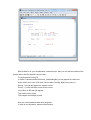
You will see the following text on your LCD Screen:
HTTP/1.1 200 OK
Date: Tue, 10 Jul 2012 14:03:21 GMT
Server: Apache/2.2.22 (Win32)
Last-Modified: Sat, 20 Nov 2004 11:16:26 GMT
ETag: "c000000002021-2c-3e94ec1117680"
Accept-Ranges: bytes
Content-Length: 44
Keep-Alive: timeout=5, max=100
Connection: Keep-Alive
Content-Type: text/html
<html><body><h1>It works!</h1></body></html>
This was getting from the Apache Server you have installed on a desktop PC.
Editing the file index.html you will get not only "It works!" but any other text in real time.
Using the Print_Page function with Font 4x6 you can get output onto Mini210s LCD or remove
remarks and it will be outputted onto connected COM Port.
DNS are not supported by now, so you must find the Server's IP - you can use the ping
command:
ping www.example.com and it will give you an IP address of the Site.
Getting the page, you can retrieve the data page contains (temperature, pressure, and so on.)
And you can make a simple PHP script on your own Internet Site. This program will collect all
data for your needs and send them to your FriendlyARM board.
And last - this thing is interesting for playing with.
There is a simple SCADA video at: http://www.youtube.com/watch?v=Q2mjBy_Yor4
I began to think of making some toy project - the "Smart Doll's House".
It will control LEDs in the rooms, air fan, speak and show status on distant iPhone, Android
phone or Notebook.
Note. DHCP not implemented so I connect my Mini210s to the router.
It's not a big problem – the ISP can assign you a permanent IP address. It cost ~$5 per month in
my location.
By now I can connect Mini210s to Netgear wireless AP and Netgear Router and plan to connect
the Wi-Fi module.
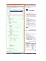
On the pages below there is the source text.
//
WEB Client / startos
#define U32 unsigned int
#define U16
unsigned short
#define U8
unsigned char
#define BUFFER_SIZE
1518
///////////////////////////////////////////////////////
U8
macaddr[6] = {0xAA,0xAD,0xBE,0xEF,0xFE,0xED};
// change it or left as is
U8
Mini210s_ip[4]
= {192,168,1,17}; // IP address of your board - change according your Network
U8
server_ip[4] = {192,168,1,5};
// the Server IP address
U8
buf
[BUFFER_SIZE+1];
// Data buffer
U8
request[] =
"GET /index.html HTTP/1.0\n"
"Host:192.168.1.5\n"
"User-Agent: startos\n"
"Accept: text/html\n"
"Keep-Alive: 300\n"
"Connection: keep-alive\n\n" ;
void
Print_Page (int x0, int y0, U8 *txt);
///////////////////////////////////////////////////////////
void
Main
(void)
{
int
res,i;
res = NIC_Init (macaddr);
if
( res == 0 )
else
// the result
{
// init NIC
Print_String(0,50,"No NIC/Link");
Buzz (8000,10);
}
{
Print_String
( 0, 30, "Connected at: " );
if
( res&1 ) Print_String(112,30," 10M h/dup");
if
( res&2 ) Print_String(112,30," 10M f/dup");
if
( res&4 ) Print_String(112,30,"100M h/dup");
if
( res&8 ) Print_String(112,30,"100M f/dup");
start:
res = Client ( Mini210s_ip, server_ip, request, buf );
// Mini210s_ip is the Client IP
if
( res )
// We got proper Page
{
Print_Page (0,0, buf+0x36 ); // Data begins at 0x36 in the buffer
// or you can send the Page to COM Port
// Uart_SendByte ( '\n') ;
// for
( i=0x36; i < res; i++) Uart_SendByte ( buf[i]) ;
}
else
goto
start;
//
if
(
!((*(int *)0x5800000c) & 0x8000) )
Delay
goto
(1000);
Exit();
start;
// if pen is pressing the screen
// cycle repeats
}
///////////////////////////////////////////////
//
the LCD width is small, so print the Page with a small Font 4x6
void
{
Print_Page
extern
unsigned short
int
int x,y,m,i;
char t,s;
y0=y0+6;
(int x0, int y0, U8 *txt)
char font4x6[];
*LCD_buffer;
LCD_X;
// move to the foot of symbol
// txt - pointer on char
}
Fill_Screen(10);
// getting the Screen buffer parameters
LCD_buffer
= (unsigned short *)((*( unsigned *)0x4d000014) << 1);
LCD_X
= (*( unsigned *)0x4d00001c);
for
{
( i = 0; txt[i]!=0; i++)
s = txt[i]&0x7F;
if
( s == '\n' )
{
x0=0;
goto
}
if
( s == '\r' )
{
if ( y0<230 )
else
goto
}
m = y0*LCD_X+x0;
do_nothing:
}
}
// get the Symbol code, valid code 0...127
// Carriage return (CR)
do_nothing;
// Line feed (LF)
y0+=10;
y0=230;
do_nothing;
// starting point
for(y=0; y<3; y++)
{
m+=LCD_X<<1;
// next Y
t=font4x6[s*3+y];
for(x=0; x<4; x++)
{
if
( t&(0x80>>x))
else
if
( t&(8>>x))
else
m++;
}
m=m-4;
}
x0+=4;
;
///////////////////////////////////////////////////////////////////////
*(LCD_buffer+m)=0xFFFF; // Draw Foreground (White)
*(LCD_buffer+m)=10;
// Draw Background (Dark Blue)
*(LCD_buffer+m+LCD_X)=0xFFFF;// Draw Foreground
*(LCD_buffer+m+LCD_X)=10; // Draw Background (Dark b.)
// next X
// restore X
// next Character place in the String
// skeep not drawing symbols CR&LF