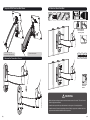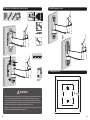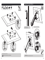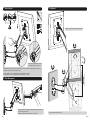
1
Maintenance
• Check that the bracket is secure and safe to use at regular intervals(at least every three months).
• Please contact your dealer if you have any questions.
PID 9744
11
NOTE: Read the entire instruction manual before you start installation and assembly.
Component Checklist
IMPORTANT: Ensure that you have received all parts according to the component checklist prior to installing. If
any parts are missing or faulty, telephone your local distributor for a replacement.
WARNING
• Do not begin the installation until you have read and understood the instructions
and warnings contained in this installation sheet. If you have any question
regarding any of the instruction or warning, please contact your local distributor.
3mm Allen key (x1)
B
• This mounting bracket was designed to be installed and utilized ONLY as
specified in this manual. Improper installation of this product may cause damage
or serious injury.
• This product should only be installed by someone of good mechanical ability,
with basic building experience and fully understanding of this manual.
6mm Allen key (x1)
C
articulated arm assembly
A
• Make sure that the supporting surface will safely support the combined load of
the equipment and all attached hardware and components.
Package M
• If mounting to wood wall studs, make sure that mounting screws are anchored
into the center of the studs. The use of a stud finder is highly recommended.
• Always use assistant or mechanical lifting equipment to safely lift and position
equipment.
M4x14 (x4)
M-A
M5x14 (x4)
M-B
M6x14 (x4)
M-C
M8x20 (x4)
M-D
• Tighten screws firmly, but do not over tighten. Over tightening can damage the
items, greatly reducing their holding power.
• This product is intended for indoor use only. Using this product outdoors could
lead to product failure and personal injury.
D5 washer (x4)
M-E
D8 washer (x4)
M-F
small spacer (x8)
M-G
Package W
ST6.3x55 (x3)
W-A
1
concrete anchor (x3)
W-B
2
3a. Mount on Wood Stud Wall
1. Separate VESA Plate from Wall Mount
55mm
((2.2")
2.2")
ø 4.5mm
(ø 3/16")
1
2
Find and mark the
exact location of
mounting holes
3
Drill pilot holes
· Loosen the upper nut,
· Remove the lower flat nut.
Remove VESA plate .
√
2. Remove the Decorative Covers
X
X
W-A
Screw the wall
mount onto
the wall
WARNING
• Make sure that mounting screws are anchored into the center of the studs. The use of a stud
finder is highly recommended.
• Installers are responsible to provide hardware for other types of mounting situations.
• Installers must verify that the supporting surface will safely support the combined load of the
equipment and all attached hardware and components.
3
4
4. Install Decorative Covers
3b. Mount on Solid Brick and Concrete Block
60mm
((2.4")
2.4")
ø 10mm
(ø 3/8")
1
Mark the exact
location of
mounting holes
2
Drill pilot holes
W-B
√
X
X
W-A
5. Install VESA Plate
Screw the wall
mount onto
the wall
WARNING
Top of TV
• When installing wall mounts on cinder block, verify the actual concrete thickness is at least
1-3/8" (35mm) for using the concrete anchors. Do not drill into mortar joints! Be sure to
mount in a solid part of the block, generally 1" (25mm) minimum from the side of the block.
It is suggested electric drill on slow setting be used to drill the hole instead of a hammer drill
to avoid breaking out the back of the hole when entering a void or cavity.
• Installers must verify that the supporting surface will safely support the combined load of the
equipment and all attached hardware and components.
5
6
6. Hook the TV onto the Wall Mount
TV
TV
TV
TV
4mm
M-A/M-B
M-C/M-D
M-E
M-F
Loosen the upper nut spacing
4mm to VESA plate.
or
Hook the TV onto the wall mount
M-D
M-D
M-F
M-F
M-G
M-G
M-G
Screw VESA plate onto the TV.
Tighten all screws but do not over tighten.
7
· Level the TV.
· Place the lower flat nut and tighten both nuts.
8
9. Adjustment
7. Tension Adjust
Tighten screw till the display angle can be fixed.
B
180°
C
+3°
+15°
-15°
Please tighten socket set screw if the
joints make popping sounds in use.
Please keep the arm level during tension adjustment. Use a proper Allen key to slightly loosen or tighten the
adjustment screw according to the display weight.
-3°
180°
max335mm
8. Cable Management
height adjustable
180°
If display settles on its own, rotate adjustment screw towards the "+" symbol.
If display rises on its own, rotate adjustment screw towards the "-" symbol.
FOLD 3
DUSTCATCHE
R
Connect the cables to the display, and press cable cover inward to route
the cables through the space.
Note: Leave slack in cable for cantilever arm movement.
9
Adjust to the desired location or tilt.
10