1
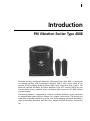
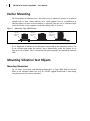
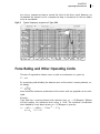
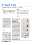
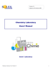
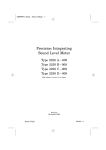
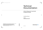
Cover.fm Page 1 Thursday, June 1, 2006 10:00 AM
Technical
Documentation
PM Vibration Exciter Type 4808
HEADQUARTERS: DK-2850 Nærum · Denmark · Telephone: +45 4580 0500 · Fax: +45 4580 1405 · www.bksv.com · [email protected]
Australia (+61) 2 9889-8888 · Austria (+43) 1 865 74 00 · Brazil (+55)11 5188-8161 · Canada (+1) 514 695-8225
China (+86) 10 680 29906 · Czech Republic (+420) 2 6702 1100 · Finland (+358) 9-755 950 · France (+33) 1 69 90 71 00
Germany (+49) 421 17 87 0 · Hong Kong (+852) 2548 7486 · Hungary (+36) 1 215 83 05 · Ireland (+353) 1 807 4083
Italy (+39) 0257 68061 · Japan (+81) 3 5715 1612 · Republic of Korea (+82) 2 3473 0605 · Netherlands (+31)318 55 9290
Norway (+47) 66 77 11 55 · Poland (+48) 22 816 75 56 · Portugal (+351) 21 4169 040 · Singapore (+65) 377 4512
Slovak Republic (+421) 25 443 0701 · Spain (+34) 91 659 0820 · Sweden (+46) 33 225 622 · Switzerland (+41) 44 8807 035
Taiwan (+886) 2 2502 7255 · United Kingdom (+44) 14 38 739 000 · USA (+1) 800 332 2040
Local representatives and service organisations worldwide
ËBE-0194---*Î
User Manual
English BE 0194 – 13
PM Vibration Exciter Type
4808
User Manual
BE 0194−13
June 2006
Safety Considerations
This apparatus has been designed and tested in accordance with IEC 61010 – 1 and
EN 61010 – 1 Safety Requirements for Electrical Equipment for Measurement, Control and Laborator y Use. This manual contains information and warnings which
must be followed to ensure safe operation and to retain the apparatus in safe condition. Special note should be made of the following:
Safety Symbols
The apparatus will be marked with this symbol when it is important that you
refer to the associated warning statements given in the manual.
Protective Earth Terminal
Hazardous Voltage
Explosion Hazard
The equipment is not designed to be used in potentially explosive environments. It
should not be operated in the presence of flammable liquids or gases.
Warnings
•
•
•
Switch off all power to equipment before connecting or disconnecting their digital interface. Failure to do so could damage the equipment.
Whenever it is likely that the correct function or operating safety of the apparatus has been impaired, it must be made inoperative and be secured against
unintended operation.
Any adjustment, maintenance and repair of the open apparatus under voltage
must be avoided as far as possible and, if unavoidable, must be carried out
only by trained service personnel.
• Do not dispose of electronic equipment as unsorted municipal waste
• It is your responsibility to contribute to a clean and healthy environment by
using the appropriate local return and collection systems
• Hazardous substances in electronic equipment may have detrimental effects
on the environment and human health
• The symbol shown to the left indicates that separate collection systems must
be used for any discarded equipment marked with that symbol
• Waste electrical and electronic equipment may be returned to your local
Brüel & Kjær representative or to Brüel & Kjær Headquarters for disposal
Copyright © 1984, 2003, Brüel & Kjær Sound & Vibration Measurement A/S
All rights reserved. No part of this publication may be reproduced or distributed in
any form, or by any means, without prior written consent from Brüel & Kjær
Sound & Vibration Measurement A/S, Nærum, Denmark
Table of Contents
INTRODUCTION
PM Vibration Exciter Type 4808......................................................................... 1
CHAPTER 1
Operation ............................................................................................................ 3
Cooling ..................................................................................................................................... 3
Exciter Mounting ..................................................................................................................... 4
Mounting Vibration Test Objects............................................................................................ 4
CHAPTER 2
Operating Characteristics ................................................................................... 9
Construction ............................................................................................................................. 9
Frequency Response and Resonance .................................................................................... 10
Force Rating and Other Operating Limits ............................................................................ 11
CHAPTER 3
Specifications .................................................................................................... 13
INDEX ...................................................................................................................................... 15
1
Introduction
PM Vibration Exciter Type 4808
Designed for long, trouble-free operation, Vibration Exciter Type 4808 is a high-quality compact machine with a permanent magnetic field. It has a force rating of 112
newton (25 lbf) enabling relatively heavy loads to be excited to high g levels. The
4808 will normally be driven by Power Amplifier Type 2719 rated at 180 VA but can
also be driven by any amplifier up to a maximum input current of 15 A RMS without
assisted cooling.
The moving element is supported by a robust rectilinear guidance system consisting
of grouped radial and transverse flexures in a unique construction. The flexures are
made from a bonded sandwich of spring steel and a damping elastomer, providing a
clean acceleration waveform with low cross motion and low distortion characteristics.
2
PM Vibration Exciter Type 4808 – User Manual
3
Chapter 1
Operation
Cooling
Vibration Exciter Type 4808 can be used in environments with ambient temperatures
up to 40 °C (104 °F). Its maximum drive current rating is 15 A RMS, but with assisted
cooling this can be raised to 25 A RMS. Without assisted cooling, operation at
15 A RMS will cause the vibration table to become hot, but will not damage the
exciter.
The most efficient method of cooling is to suck air into the exciter via the air filter
vents at the top of the exciter body. For this purpose a domestic vacuum cleaner
can be used with its suction hose connected to one of the hollow carrying handles
on the side of the exciter.
Note: Using a vacuum cleaner to blow air into the exciter is not recommended as it
may pre-heat the air.
To ensure an adequate flow of air around the vibration table’s drive coil:
1) Unscrew and remove one of the exciter’s carrying handles.
2) Fit the ½″ standard tube thread insert (provided) into the hole in the exciter
body.
3) Attach the vacuum cleaner’s suction hose.
4) If suction causes the vibration table to sink more than 1 mm below its normal
position, shift the position of the hose to give larger openings in the slots on the
outside of the insert.
4
PM Vibration Exciter Type 4808 – User Manual
Exciter Mounting
For the majority of vibration tests, the easiest way to mount the exciter is to place it
upright with its base resting directly on a solid support such as a workbench or
concrete floor. If a more secure mounting is required, you can use ½″ diameter bolts
to fix the exciter to the support via the four fixing holes in its base.
Fig.1.1
Mounting Type 4808 Exciter
1/2 inch
Diameter
Bolts
Vibration
Absorbent
Pad
Vibration
Absorbent
Cushion
030060
If it is important to minimise the vibrations transmitted to the mounting surface, use
a soft, resilient pad under the exciter’s base. Alternatively, place the exciter on its
side on a soft cushion. This is convenient for exciting panels or frameworks horizontally.
Mounting Vibration Test Objects
Mounting Dimensions
Fig.1.2 shows the outline and mounting dimensions of Type 4808. Each of the five
holes in the vibration tables has an 5/16″–18 UNC tapped thread and is 8 mm deep,
accepting one of the inserts provided.
CHAPTER 1
5
Operation
Fig.1.2
Outline and mounting
dimensions of 4808
215mm
6
62mm
20
60
175
200
½"
BS Pipe
Thread
219
5 x 5/16"- 18 UNC
for M5 and 10 - 32 UNF
inserts. One central
insert plus four
equi-spaced on circle of
50.8mm dia.
Thread Inserts:
M5 - YS 0810
10 - 32 UNF - YS 0811
4 pin NEUTRIK Speakon
(NL3MP)
14 mm dia.
179.5
030062
To prevent damage to the exciter, a test object should be mounted with its centre of
gravity in line with the central fixing hole. Avoid fastening test objects directly to the
fixing holes – use the threaded inserts provided.
Threaded Inserts
Two types of threaded insert are provided for fixing vibration test objects:
!
YS 0810 converts the 5/16″–18 UNC thread of the vibration table’s fixing holes to M5
!
YS 0811 converts the 5/16″–18 UNC thread to 10–32 UNF
6
PM Vibration Exciter Type 4808 – User Manual
The inserts act as mechanical fuses which strip their inner thread before excessive
force or fastening torque can strip the thread of the vibration table’s fixing holes.
The correct fastening torque is approximately 0.35 kg m (30 lb. in.). To prevent this
from being exceeded, we recommend that you use a torque wrench when screwing
test objects or fixtures to the vibration table.
Mounting Tool QA 0061 is provided for fitting inserts. This has a locating pin at the
end of its screw blade which fits into the threaded hole of an insert and prevents
the tool from slipping sideways while the inserts are being screwed into the vibration table. When properly fitted, the inserts should be approximately 1 mm (0.04″)
below the top of the table. Never bottom an insert in the fixing hole and always
ensure that the insert and hole are clean.
To lock an insert in place, apply a small drop of cement to its outer thread before
screwing it in. A suitable thread locking cement is available under Brüel & Kjær part
no. QS 0003. To unscrew a locked insert, you can weaken the cement by using a
soldering iron to heat the insert.
Test Fixtures
Since the points at which a test object can be attached do not always match the
arrangement of fixing holes in the vibration table, it is often necessary to make a
fixture for fastening the object. To prevent plate resonances from influencing the
vibration response of the test object, the dimensions of the fixture should be as
small as possible.
Stingers and Pushrods
For vibration mode studies on panels or other large structures, it is generally convenient to have a central driving point away from the exciter. For this purpose a
stinger, such as a nylon stinger from Stinger Kit WZ 0066, or a purpose-built pushrod
can be used to transfer the force from the fixing hole at the centre of the vibration
table. An example of the purpose-built pushrod is shown in Fig.1.3.
Fig.1.3
Typical pushrod for use with Type 4808
Hose Clamp
Thin Aluminium Tube
10-32 UNF
Slot
030061
Connection of Power Amplifier
Drive Cable AQ 0649 is provided with the exciter for connection of a power amplifier
to the vibration table drive coil. Its plug connections are as shown in Fig.1.4, and it
is suitable for direct connection to the Power Output socket of Power Amplifiers
Types 2718 and 2719.
CHAPTER 1
7
Operation
Fig.1.4
Drive Cable AQ 0649
connections viewed
from the outside
AQ 0649: Soldering side of Plug shown
Brown
+1
+1
Yellow/Green
-1
-1
-2
+2
-2
+2
Blue
Black
010113/2
If there is a mains hum when powering the exciter, the power amplifier and exciter
are probably grounded at more than one point. To prevent this, isolate the base of
the exciter from ground, or, alternatively, disconnect the Amplifier Chassis – Exciter
Body connection (the yellow/green coloured cord between the two “–2” terminals) in
the AQ 0649 cable at one of the two plugs.
Note: To connect with an old Brüel & Kjær Power Amplifier Type 2712, you must
remove one of the Neutrik 4-pin Speakon plugs from Drive Cable AQ 0649, and replace it with 3-pin Cannon Plug, Brüel & Kjær Part No. JP 0308 that has to be soldered on. The connections are shown in Fig.1.5.
Fig.1.5
Drive Cable AQ 0649
with one of the Neutrik
4-pin Speakon plugs
replaced with JP 0308
4808
Exciter Drive
Input Socket
Drive Signal (Coil Start)
+1
-1
Power Amplifier Type 2712
Output Socket, accepts
Cannon Plug JP 0308
1
2
-2
+2
3
Neutral (Coil Finish)
030067
8
PM Vibration Exciter Type 4808 – User Manual
9
Chapter 2
Operating Characteristics
Construction
Fig.2.1
A sectional view of
Vibration Exciter Type
4808
Coil
Vibration
Table
Rubber
Boot
Radial
Flexure
Vertical
Flexure
Radial
Flexure
Epoxy
Resin
Cast Iron
Flange
Iron
Pole Piece
Columax
Permanent
Magnet
030063
Magnetic Assembly
Type 4808 has a Columax alloy permanent magnet which is epoxy bonded to the
base. The thick metal base and cylindrical body of the exciter are machined from
mild steel and form part of the magnetic path. A high purity, cylindrical, iron pole
piece projects from the magnet into the hole at the centre of a cast iron flange. This
is fixed to the top of the exciter body and creates a 2.55 mm (0.1″) field gap around
10
PM Vibration Exciter Type 4808 – User Manual
the pole piece. A magnetic field of approximately 1 Tesla (104 Gauss) is produced in
this gap. To help ensure a uniform gap and homogenous field, a special jig is used to
centre the flange. Outside the gap, the field strength is less than 0.02 Tesla which will
not harm sensitive equipment or wristwatches used near the exciter.
Moving Element
The moving element is a thin hollow cylinder with a vibration table at one end and a
moving coil at the other. It is designed to provide the best possible coupling between the force generated by the drive coil and the test object on the vibration
table. For maximum bare table acceleration and a high resonance frequency, it has
been machined from a solid piece of lightweight aluminium. The vibration table is
lapped and hardened by a deep electro-chemical process to provide a smooth, durable coupling with test objects.
The drive coil mounted at the bottom of the moving element is made up, of two
parallel windings. These are coupled to a 4-pin Speakon plug on the side of the
exciter body. When connected in parallel, they have a nominal impedance of 0.8 Ω.
The maximum drive current rating is 15 A RMS, which can be extended to 25 A RMS
with assisted air cooling.
Eight radial flexures support the moving element in the field gap of the magnet
assembly. These are placed in sets of four above and below the gap and are fastened, by four vertical flexures, to the sides of the cast iron flange at the top of the
assembly. The flexures accurately align the moving element so that the drive coil is
centred in the gap, allowing it to move up and down without twisting or rubbing
against the sides of the gap. Each flexure is a sandwich of spring steel plate bonded
with rubber. This helps damp the resonance modes of the suspension.
The maximum displacement limit of the moving element os 12.7 mm (0.5″) peak-topeak. Rubber stops above and below the gap help protect the element from overtravel. The stops are designed to withstand an occasional high-velocity impact and
are for emergency use only. If the flexures hit the stops, a bumping sound will be
heard, warning you to reduce the drive level immediately.
Frequency Response and Resonance
Fig.2.2 shows a plot of the frequency response of a Type 4808. The acceleration level
is in g and ms–2 and is plotted against frequency for a constant drive voltage. The
acceleration level increase with frequency to reach a damped peak at about 150 Hz.
This is the “electro-mechanical” resonance, a result of the back e.m.f. induced in the
moving coil damping the suspension resonance of the exciter. The acceleration level
then remains constant from 300 Hz to 4 kHz, after which it climbs steeply to a peak
at about 12 kHz. This peak is the major axial resonance of the moving element. It can
be seen that the exciter can be used at frequencies between 300 Hz and 4 kHz with-
CHAPTER 2
Operating Characteristics
11
out using a compressor loop to control the level of the drive signal. However, we
recommend the general use of a compressor loop as resonances in the test object
must be considered.
Fig.2.2
Typical frequency response of Type 4808
030064
Force Rating and Other Operating Limits
The force F required to vibrate a mass m with an acceleration a is given by:
F = ma
By rearranging and including the effective mass of the exciter’s moving element, me,
we obtain:
F a = -----------------m + me
from which the maximum acceleration of the exciter with any payload can be calculated.
Example:
Type 4808 has a moving element with effective mass me = 0.16 kilogram. Without
assisted cooling, the maximum force rating is 112 N. The maximum acceleration
when loaded by a test object of mass m = 0.5 kilogram is given by:
F - = ----------------------112 - = 170 ms –2 = 17.3 g
a = -----------------m + me
0.5 + 0.16
12
PM Vibration Exciter Type 4808 – User Manual
Fig.2.3
Performance limits for sine operation of Type 4808 with and without assisted
cooling
030065
The maximum acceleration with other loads can be determined from the load rating
curves in Fig.2.3. Above 150 Hz the limits are based solely on the available force.
However, for a given acceleration level, displacement increases as frequency decreases. Therefore, at frequencies up to 40 Hz the exciter must be held within its
12.7 mm (0.5″) maximum displacement limit in order to avoid hitting the overtravel
stops.
At frequencies from 40 to 150 Hz, the maximum acceleration available is determined
by the velocity limit which depends on the voltage available from the power amplifier used to drive the exciter.
13
Chapter 3
Specifications
RATED FORCE
112 N, 25 lbf sine-peak (with assisted air cooling
187 N, 42 lbf peak)
FREQUENCY RANGE
5 Hz to 10 kHz bare table
AXIAL RESONANT FREQUENCY
10 kHz bare table
MAXIMUM BARE TABLE ACCELERATION
700 m/s2 (71 g)
MAXIMUM DISPLACEMENT
12.7 mm (0.5 in) peak-to-peak
MAXIMUM VELOCITY
1.4 m/s (55 in/s)
DYNAMIC WEIGHT OF MOVING ELEMENT
160 gram (0.35 lb)
STATIC FLEXURE STIFFNESS
5.6 N/mm (32 lbf/in)
MAXIMUM INPUT CURRENT
15 A RMS (with assisted air cooling 25 A RMS)
CURRENT-TO-FORCE RATIO
Coils in parallel: approximately 0.16 A/F (sine peak)
Coils in series: approximately 0.08 A/F (sine peak)
STRAY MAGNETIC FIELD
20 × 10–3 Tesla at table face
8 × 10⁻³ Tesla at 12.7 mm (0.5 in) above table face
COIL IMPEDANCE
Approximately 0.8 Ω at 500 Hz with bare table and
coils in parallel
TABLE SIZE
62.5 mm (2.45 in) diameter
FASTENING THREAD
5 × 5/16″ – 18 UNC for M5 and 10–32 UNF inserts.
1 central insert plus 4 equi-spaced on circle of
∅50.8 mm
TOTAL WEIGHT
35 kg (77.1 lb.)
DIMENSIONS
Diameter: 215 mm (8.46 in)
Height: 200 mm (7.87 in)
COMPLIANCE WITH STANDARDS
compliance with EMC Directive
compliance with EMC Requirements of
Australia and New Zealand
Safety, EMC Emission and Immunity:
According to relevant standards: EN 61010 –1,
IEC 61010–1, UL 3111–1, EN 50081 –1/2, IEC 61000–
6–1/2/3/4, EN 61326–1, CISPR22 Class B limits, FCC
Rules Part 15, EN 50082–1/2, EN 61326–1
Temperature: According to IEC 60068–2–1 &
IEC 60068–2–2
Operating temperature: +5 to +40°C (41 to 104°F)
Storage temperature: –25 to +70°C (–13 to 158°F)
Humidity: According to IEC 60068–2–3, Damp Heat:
90% RH (non-condensing at 40°C (104°F))
Mechanical: Non-operating according to IEC 60068–
2–6, IEC 60068–2–27, IEC 60068–2–29
14
PM Vibration Exciter Type 4808 – User Manual
15
Index
A
AQ 0649 .................................................... 7
C
Cannon plug ............................................. 7
Compliance with Standards ................... 13
Construction ............................................. 9
Cooling ...................................................... 3
D
Dimensions ............................................... 4
Drive cable .......................................... 6, 7
E
Exciter mounting ...................................... 4
F
Force rating ............................................ 11
Frequency response ................................ 10
J
JP 0308 ...................................................... 7
M
Magnetic assembly ................................... 9
Mains hum ................................................ 7
Maximum acceleration .......................... 12
Mounting .................................................. 4
Mounting dimensions .............................. 4
Mounting tool .......................................... 6
Moving element ..................................... 10
O
Operating characteristics ......................... 9
Operating limits ..................................... 11
Operation ................................................. 3
P
Power amplifier ............................ 1, 6, 7
Pushrods ................................................... 6
Q
QA 0061 .................................................... 6
QS 0003 ..................................................... 6
R
Resonance
.............................................. 10
S
Specifications ......................................... 13
Standards ................................................ 13
Stingers ..................................................... 6
T
Test fixtures ..............................................
Test objects ...............................................
Threaded inserts ......................................
Type 2712 .................................................
Type 2718 .................................................
Type 2719 ........................................... 1,
6
4
5
7
6
6
V
Vibration test objects
.............................. 4
Y
YS 0810 ..................................................... 5
YS 0811 ..................................................... 5
16
PM Vibration Exciter Type 4808 – User Manual
Cover.fm Page 1 Thursday, June 1, 2006 10:00 AM
Technical
Documentation
PM Vibration Exciter Type 4808
HEADQUARTERS: DK-2850 Nærum · Denmark · Telephone: +45 4580 0500 · Fax: +45 4580 1405 · www.bksv.com · [email protected]
Australia (+61) 2 9889-8888 · Austria (+43) 1 865 74 00 · Brazil (+55)11 5188-8161 · Canada (+1) 514 695-8225
China (+86) 10 680 29906 · Czech Republic (+420) 2 6702 1100 · Finland (+358) 9-755 950 · France (+33) 1 69 90 71 00
Germany (+49) 421 17 87 0 · Hong Kong (+852) 2548 7486 · Hungary (+36) 1 215 83 05 · Ireland (+353) 1 807 4083
Italy (+39) 0257 68061 · Japan (+81) 3 5715 1612 · Republic of Korea (+82) 2 3473 0605 · Netherlands (+31)318 55 9290
Norway (+47) 66 77 11 55 · Poland (+48) 22 816 75 56 · Portugal (+351) 21 4169 040 · Singapore (+65) 377 4512
Slovak Republic (+421) 25 443 0701 · Spain (+34) 91 659 0820 · Sweden (+46) 33 225 622 · Switzerland (+41) 44 8807 035
Taiwan (+886) 2 2502 7255 · United Kingdom (+44) 14 38 739 000 · USA (+1) 800 332 2040
Local representatives and service organisations worldwide
ËBE-0194---*Î
User Manual
English BE 0194 – 13