1
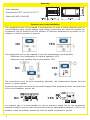
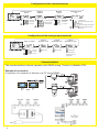
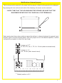
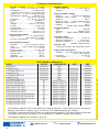
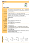
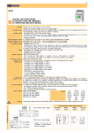
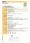
User’s manual
F
Segle XX, 91
E08032 - Barcelona
(
T: +34 934 560 995
F: +34 934 354 532
ü
www.disibeint.com
[email protected]
Programmable panel meter
IPD
Assembly
Wall assembly:
Window of 46 x 91+0,5
mm (2.5" x 3.5" +0,2
-0
-0 )
Made with ABS (UL94-HB)
General cares in the installation
The equipments must not be placed in environments too near to power elements such us
circuit breakers, triacs, rectifier bridges, high voltage transformers, etc. As far as possible, the
equipments will be isolated from the emitters of electrical disturbances by means of, for
instance, a shield connected to ground.
NO
YES
The equipments will not be exposed to extreme temperatures and humidities:
· Maximum room temperature for optimal operation: 40ºC
· Maximum room humidity without precipitation: 90%.
NO
YES
The connections must be done separating, phisically, the measurement signals from the
control or power signals.
Do not use the same connection for the power supply of the equipment and for the control line
of the circuit breakers, motors, etc.
NO
YES
In a general way, it is recommended to use an exclusive supply line for the equipments
connected directly from the main and provided with the appropiate protections. If this is not
possible, install an isolation transformer with the shield connected to ground.
2
Cautions with the connection
Before applying the supply voltage or the signals, be sure that the wiring is correct.
In the current analog inputs, check that the polarity is the right one and the shunt is present. If
it is internal, by means of the proper jumper and if it is external, checking that the shunt resistance
(3,74 ohm) is connected to the right terminals.
In the Pt 100 inputs, checking the third wire will avoid saturated indications.
In the inputs for mV and termopar, beside to the polarity is important to assure that the internal
shunt of that channel is not selected.
Every voltage between terminals higher than 3 V, from the same channel or between different
channels, may cause damages in the equipment.
It is always recommended to use twisted wire cable with shield for the signal lines and to use
different pipelines than the ones for power or control.
For a right shielding, connect it to a good quality ground (instrumentation ground) in only one
of the sides. Do never connect to ground both sides of the shield.
Avoid, as far as possible, the electrical ground where the circuit breakers, motors and power
units are connected to. Usually, due to the deficient quality of these type of grounds, they are a
source of electrical disturbances.
It is recommended to use 1 mm2 cooper cable for the signals to be measured.
The connection of the communications must be exclusively done with twisted and shielded
cable.
Inputs connection
Internal jumper S1 in position 2-3 (page. 7)
Internal jumper S1 en posición 1-2 (page 7)
3
Descripcion of the front screen
Measure
Status of the
digital inputs
TAG
Status of the
digital outputs
Keyboard
Error messages
At any place, returns to the
preceeding menu.
Check probe and connections
Measure is over the high limit or 9999
Advance to the next step.
Data validation.
Measure is over then low limit or -1999
Increases value
Decreases value
Main menu
Starting
screen
Alarm 1
setting
Change value
Alarm 2
setting
Change value
Alarm 3
setting
Change value
Menú configuración
Desde cualquier pantalla del menú regresa a la pantalla de inicio
Pantalla
inicial
Hasta que
cambie el menú
Configuración
Entrada Analógica
4
Configuración
Alarmas
Configuración
Configuración Salida Analógica
Comunicaciones
(opcional)
Configuration of the analog input
Defines type of input
Type
Termopar
-Type B
-Type R
-Type S
-Type N
Indication
physical
units
Noise
filter
-Type E
-Type K
-Type S
-Type T
Peaks
filter
0-15
Minimum
limit
-No decimal
-1 decimal
-2 decimals
-3 decimals
Change value
Maximum
limit
Average
filter
0-9
Text editor
of lower line
of main screen
Change value
Change value
Advance letter
Change value
No linealization
Number of
decimals
Reading
correction
Linealización
Change value
Linealization editor
Linealization editor
PXX - Indication of the linealization point being edited
Repeat this process for all the
required linealization points.
Select the linealization point
from 1 to 20. When point 0 is
selected, the linealization
editor is exited.
Measure reading
before to linealizate in
the edited point.
Measure reading
after to linealizate in
the edited point.
Configuration of the alarms (AL1, Al 2, AL3)
Function output
Relay contact
- Non active alarm
- Maximum alarm
- Normally opened
Hysteresis
of the alarm
Change value
- Normally closed
- Maximum alarm
- Window alarm
- Regulation T/N low reverse (heat)
- Regulation T/N high direct (cold)
- Regulation T/N symmetric reverse (heat)
- Regulation T/N symmetric direct (cold)
5
Configuration of the communications
Communication
speed
Modbus
address
- 38400 bps
- 19200 bps
- 9600 bps
Modbus
speed
No communication
Communication
test
- High speed
- No Rx and Tx
- Receive messages not for him
- Standard
- Low speed
Addresses of the
communications
- Answer
- Receive message with CRC error
- Receive message with wrong
command
Configuration of the analog output (optional)
Type of output
- No output
- 0-20 mA
Output
minimum limit
Change value
Output
maximum limit
Change value
Output
measured in error
Change value
When the measure
shows Err, this value
is generated
- 4-20 mA
Communications
The communications channel operates with RS485 wiring. Protocol is ModBus RTU.
Example of connection
Connection of a network of devices to a PC using RS485.
Conversion
options
PC
Connector Sub-D
9 pins Female
6
Modification of internal jumpers
The housing must be opened in the case that the jumpers’ default setting wants to be changed.
By pressing the two nails at each side of the housing, the cover can be removed.
EVERY TIME THAT THE HOUSING MUST BE OPENED, BE SURE THAT THE
EQUIPMENT BE WITHOUT VOLTAGE IN ALL THE TERMINALS.
Each analog input has a two positions jumper that allows to choose between the general input
and the input of mA with internal shunt. Once the jumper is set in the desired position, use the
configuration program to select the input type.
Jumper in 2-3*
Pt 100, PTC, mV, V, TP, 0-4...20 mA (without internal shunt)
Jumper in 1-2
0-4...20 mA (with internal shunt)
*
Default position is 2-3
7
Technical characteristics
- Number of inputs: ....................... 1 input
- Types: ............ PTC, TP, RTD, mV, V, mA
- Impedance: ....................... >1 MΩ (mV) &
..... internal shunt 3,75 Ω 1% 25 ppm (mA)
- Range CJC: .... 0 a 50 °C (internal sensor)
- Standards for signals: ........... IEC584 (TP)
.................................... and IEC751 (Pt 100)
- Termopar ............... J, K, R, S, T, E, N, B
- Pt 100 ..................................... -200/600 °C
- PTC .......................................... -50/150 °C
- Voltage: ....................... ±75 mV & ± 2 VDC
- Current: .................................... 0..4-20 mA
- Linealizatión: ............................... 20 steps
- Precision at 25 °C: ......................... ± 0,1%
- Sampling time: .................. 125 ms (1 ch.)
.............................................. 250 ms (2 ch.)
Logical inputs (option):
- Logical inputs ............... 3 x 220 VAC/DC
................................ (24 VAC/DC in option)
- Current consumption: ............. 2 mA máx.
Analog outputs (option):
- Quantity: ............ 1 or 2, common ground
- Type: .............. mA (V with external shunt)
- Resolution: ...................................... 13 bits
- Output ranges: ........................ 0..4-20 mA
- Precision at 25 °C: ........................ ± 0,2 %
- Refresh time: ................................. 250 ms
- Isolation: .......................................... 500 V
- Maximum load: .............................. 500 Ω
Digitals outputs:
- Relays SPST NA .......... 3 x a 250 VAC/1A
- Isolation ............................................ 500 V
Output auxiliary voltage:
- Output 1: ................. 18 VDC no stabilised
- Maximum output current: ............... 50 mA
- Isolation ............................................ 500 V
- Output 2 (opt.): .... 5 VDC stabilised (opt.)
- Maximum output current: ............... 20 mA
- Isolation ............................................ 500 V
........................ (except with analog output)
Communications:
- Type: ............................................. RS-485
- Protocol: ............................... Modbus RTU
- Speed: ........... 9600, 19200, 38400 bauds
Operation limits:
- Ambient temperature: .............. 0 a 50 °C
- Storage temperature: ............ -20 a 70 °C
- Relative humidity: .............. máx. 85 HR%
................................ (without condensation)
Directive CE:
- Emmision/Inmunity: EN 50081/EN 61000
Supply and consumption:
- Voltage: ..... 60..250 VAC & 22..250 VDC
.................................... 20..60 VAC (option)
- Frequency: ................................. 50..60 Hz
- Consumption: .................................... 2 VA
CONCEPT
MEASURE (AI1)
ALARM SET 1 (AL 1)
HYSTERESIS ALARM 1 (AL 1)
ALARM SET 2 (AL 2)
HYSTERESIS ALARM 2 (AL 2)
ALARM SET 3 (AL 3)
HYSTERESIS ALARM 3 (AL 3)
READ STATUS ALARM 1 (AL 1)
READ STATUS ALARM 2 (AL 2)
READ STATUS ALARM 3 (AL 3)
READ STATUS OUTPUT 1 (DO 1)
READ STATUS OUTPUT 2 (DO 2)
READ STATUS OUTPUT 3 (DO 3)
WRITE STATUS OUTPUT 1 (DO 1) remote mode
WRITE STATUS OUTPUT 2 (DO 2) remote mode
WRITE STATUS OUTPUT 3 (DO 2) remote mode
STATUS DIGITAL INPUT 1 (DI 1)
STATUS DIGITAL INPUT 2 (DI 2)
STATUS DIGITAL INPUT 3 (DI 3)
DATATYPE
Word with sign
Word with sign
Word with sign
Word with sign
Word with sign
Word with sign
Word with sign
Bit
Bit
Bit
Bit
Bit
Bit
Bit
Bit
Bit
Bit
Bit
Bit
MODBUS REGISTER
30011
40035
40036
40038
40039
40041
40042
30001 BIT 9 (30001.9)
30001 BIT 10 (30001.10)
30001 BIT 11 (30001.11)
30002 BIT 2 (30002.2)
30002 BIT 3 (30002.3)
30002 BIT 4 (30002.4)
40095 BIT 0 (40095.0)
40095 BIT 1 (40095.1)
40095 BIT 2 (40095.2)
30001 BIT 5 (30001.5)
30001 BIT 6 (30001.6)
30001 BIT 7 (30001.7)
LIMITS
-32767/32768
-32767/32768
-32767/32768
-32767/32768
-32767/32768
-32767/32768
0 OFF/1 ON
0 OFF/1 ON
0 OFF/1 ON
0 OFF/1 ON
0 OFF/1 ON
0 OFF/1 ON
0 OFF/1 ON
0 OFF/1 ON
0 OFF/1 ON
0 OFF/1 ON
0 OFF/1 ON
0 OFF/1 ON
MODE
Only Read
Read/Write
Read/Write
Read/Write
Read/Write
Read/Write
Read/Write
Only Read
Only Read
Only Read
Only Read
Only Read
Only Read
Read/Write
Read/Write
Read/Write
Only Read
Only Read
Only Read
The Modbus registers with format 300xx are reading adresses. They belong the the command 3
Modbus which allow a reading up to a maximum of 9 Modbusregisters per reading.
The Modbus registers with format 400xx are reading/writing adresses. They belong the the command
16 Modbus which allow a reading up to a maximum of 3 Modbus registers per reading.
The Modbus registers are showed in decimal.
)
8
Segle XX, 91
E08032-Barcelona
+34 934 330 370
℡ T:F: +34
934 354 532
www.disibeint.com
Þ [email protected]
DISIBEINT reserves the right to alter this document wiwhout previous notice.
Basic Modbus addresses
User’s manual
F
Segle XX, 91
E08032 - Barcelona
(
T: +34 934 560 995
F: +34 934 354 532
ü
www.disibeint.com
[email protected]
Programmable panel meter
IPD