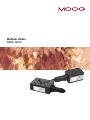
1
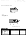
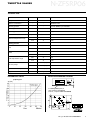
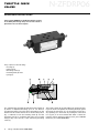
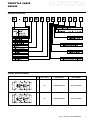
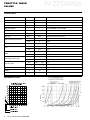
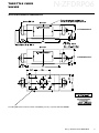
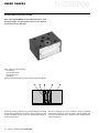
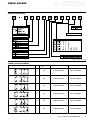
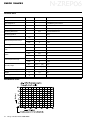
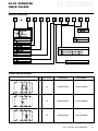
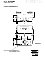
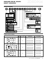
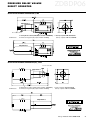
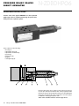
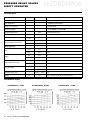
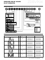
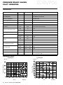
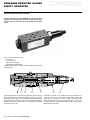
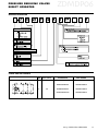
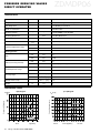
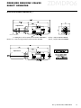
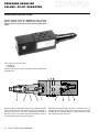
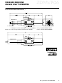
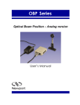
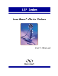
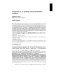
Modular Valves
NG06, NG10
OVERVIEW
Size 06 Section
Overview
MODULAR VALVES
Page
3
Throttle Valves
4-5
Throttle Check Valves
6-7
Check Valves
10-13
Pilot Operated Check Valves 14-17
Pressure Relief Valves
18-29
Pressure Reducing Valves
30-37
Size 10 Section
Page
Throttle Check Valves
38-41
Check Valves
42-45
Pilot Operated Check Valves 46-49
Pressure Relief Valves
50-61
Pressure Reducing Valves
62-69
This catalog is for users with technical knowledge.
To ensure that all necessary characteristics for function and safety of the system are given, the user has
to check the suitability of the products described
herein. In case of doubt, please contact Moog.
Moog • Modular Valves NG06-NG10
3
Part No. CDL6825 500-463 01/03
Size 06
Excerpt from Moog
Modular Valve
User’s Manual
This is a portion of a user’s manual made available in segments on the website for the
convenience of our customers. If you have questions or need additional information please
contact us.
This manual describes the functionality and features of the present Modular Valves.
Information contained herein is subject to change without notification and should not be
construed as a commitment by Moog Inc. This manual is periodically reviewed and revised.
Moog Inc. assumes no responsibility for any errors or omissions in this document. Critical
evaluation of the manual by the user is welcomed. Your comments will assist us in future
product documentation.
Copyright © 2003 by Moog Inc. All rights reserved.
.
Moog Inc.
Industrial Controls Division
East Aurora, NY 14052-0018
Telephone: 716/652-2000
Fax: 716/687-7910
Toll Free: 1-800-272- MOOG
See www.moog.com to find the location nearest you.
N!ZFSRP"#
THROTTLE VALVES
DESCRIPTION OF FUNCTION, SECTION
Throttle valve type N-ZFSRP06 throttles or completely
stops flow from either direction.
They comprise of the following:
• housing (1)
• throttling screw (2)
• hex. skt. grub screw (3), and a
• dome nut (4).
To access the screwdriver adjustement, remove the
dome nut (4).
Positive stops govern the end positions. Sealing is by the
use of a seal plate and four O-rings (5).
SYMBOL AND PART NUMBERS
4
Moog • Modular Valves NG06-NG10
NG
Qmax. [l/min]
DESIGNATION
PART NUMBER
6
60
N-ZFSRP06A4A2P
XEB17486-000N01
N!ZFSRP"#
THROTTLE VALVES
TECHNICAL DATA
General Data
Value
Unit
Specifications
Designation
-
-
Throttle valve
Mode of construction
-
-
Modular valve
Mounting pattern
-
-
Size 03 (NG06) as per ISO 4401
Mounting dimensions
-
mm
Mounting position
-
-
Qmax.
l/min
60
min.
°C
-25
max.
°C
+60
min.
bar
0
max.
bar
315
min.
bar
0
max.
bar
315
min.
°C
-25
max.
°C
+80
min.
mm2 • s-1 [cSt]
2,8
max.
mm2 • s-1 [cSt]
380
Operational viscositiy
ν
mm2 • s-1 [cSt]
35
Weight
m
kg
0,8
Flow max.
See Unit Dimensions
Any
Ambient temperature range
Working pressure
Inlet
Outlet
Fluid temperature range
Viscositiy range
PERFORMANCE CURVES
Pressure difference
∆p [bar]
INSTALLATION DRAWING N-ZFSRP06
∆p-Q-Diagram
4 x O-Ring NBR 9,25x1,78
(Part number: X783-00288);
Seal kit, complete: XEB17582-000N00
Moog • Modular Valves NG06-NG10
5
THROTTLE CHECK
VALVES
N!ZFDRP"#
DESCRIPTION OF FUNCTION, SECTION
Valves type N-ZFDRP06 are double throttle/check valves
in sandwich plate design. They serve to limit a main or
pilot flow of one or two user ports.
They comprise of the following:
• housing (1)
• guide nut (2)
• throttling screw (3)
• metering bush (4) and a
• spring (5).
Two symmetrically arranged throttle/check valves limit flow
by means of adjustable throttling spools in one direction
and give free return flow in the other. At metering-out, the
fluid in line A2 reaches the line A1 via the throttle position
(6), a combination from the metering bush (4) and the
throttling screw (3). To set the throttle orifice, use a four A/F
hexagon key in the end (7) of the self-locking throttling
screw (3).
6
Moog • Modular Valves NG06-NG10
The 13 A/F locknuts (8) provide additional security. Oil flowing from the line A1 pushes the metering bush (4) against
the spring (5) and allows oil to flow freely from line A1 to
A2, operating as a check valve. By rotating the valve about
its long axis, it can be mounted with either of these two
interface surfaces uppermost. One position gives a METERIN function, the other METER-OUT.
N!ZFDRP"#
THROTTLE CHECK
VALVES
ORDERING INFORMATION
Subject to technical changes
SYMBOLS AND PART NUMBERS
NG
Qmax. [l/min]
DESIGNATION
PART NUMBER
6
80
N-ZFDRP06A4A2CV
XEB17296-000N01
6
80
N-ZFDRP06A4A2CS
XEB17297-000N01
Moog • Modular Valves NG06-NG10
7
N!ZFDRP"#
THROTTLE CHECK
VALVES
TECHNICAL DATA
General Data
Value
Unit
Designation
-
-
Throttle check valve
Type designation
-
-
See Ordering Information
Mode of construction
-
-
Modular valve
Mounting pattern
-
-
Size 03 (NG06) as per ISO 4401
Mounting dimensions
-
mm
Mounting position
-
-
Qmax.
l/min
min.
°C
-25
max.
°C
+60
min.
bar
0
max.
bar
315
min.
bar
0
max.
bar
315
min.
°C
-25
max.
°C
+80
min.
mm • s [cSt]
2,8
max.
mm • s [cSt]
380
Operational viscositiy
ν
mm2 • s-1 [cSt]
35
Weight
m
kg
1,3
Cracking pressure
pO
bar
ca. 0,7 (in free flow direction)
Flow max.
Ambient temperature range
Specifications
See Unit Dimensions
Any
80 (See Performance Curves)
Working pressure
Inlet
Outlet
Fluid temperature range
Viscositiy range
PERFORMANCE CURVES
8
Moog • Modular Valves NG06-NG10
2
2
-1
-1
N!ZFDRP"#
THROTTLE CHECK
VALVES
INSTALLATION DRAWING N-ZFDRP06A4A2CV/S
The dual name plate shows the
Lock nut SW 13
Valve side
correct orientation for each function
N-ZFDRP06A4A2CS
Int. hex socket
Tightening torque
adjustment screw SW 4
Valve side
N-ZFDRP06A4A2CV
4 x O-Ring NBR 9,25x1,78 (Part number: X783-00288); Seal kit, complete: XEB17583-000N00
Moog • Modular Valves NG06-NG10
9
CHECK VALVES
N!ZREP"#
DESCRIPTION OF FUNCTION, SECTION
Check valves type N-ZREP06 are direct operated valves in sandwich plate design. They give leakfree closure in one direction
and allow free flow in the other.
They comprise of the following:
• housing (1)
• spring retainer (2)
• poppet (3) and a
• spring (4).
These last three parts belong to the slip-in poppet cartridge (5).
The stroke of the poppet (3) at the internal diameter is limited
by the spring retainer (2). The built-in spring (4) supports the
closing movement and also serves to hold the valve poppet (3)
in the closed position.
10
Moog • Modular Valves NG06-NG10
The slip-in cartridge (5) can be inverted in its bore, enabling
simple field changes from free flow IN to free flow OUT and
vice versa. The flow direction is marked on the cartridge with a
check valve symbol.
N!ZREP"#
CHECK VALVES
ORDERING INFORMATION
Subject to technical changes
SYMBOLS AND PART NUMBERS
NG
Qmax. [l/min]
DESIGNATION
PART NUMBER
6
60
N-ZREP06A4PV1R
XEB17139-000N01
6
60
N-ZREP06A4AS1R
XEB17302-000N01
6
60
N-ZREP06A4BS1R
XEB17303-000N01
6
60
N-ZREP06A4TS1R
XEB17304-000N01
6
60
N-ZREP06A4CS1R
XEB17305-000N01
6
60
N-ZREP06A4PT1R
XEB17457-000N01
Moog • Modular Valves NG06-NG10
11
N!ZREP"#
CHECK VALVES
TECHNICAL DATA
General Data
Value
Unit
Designation
-
-
Check valve
Type designation
-
-
See Ordering Information
Mode of construction
-
-
Modular valve
Mounting pattern
-
-
Size 03 (NG06) as per ISO 4401
Mounting dimensions
-
mm
Mounting position
-
-
Qmax.
l/min
min.
°C
-25
max.
°C
+60
min.
bar
0
max.
bar
315
min.
bar
0
max.
bar
315
min.
°C
-25
max.
°C
+80
min.
mm2 • s-1 [cSt]
2,8
max.
mm2 • s-1 [cSt]
380
Operational viscositiy
ν
mm2 • s-1 [cSt]
35
Weight
m
kg
0,7
Cracking pressure
pO
bar
0,5
Flow max.
Specifications
See Unit Dimensions
Any
60 (See Performance Curves)
Ambient temperature range
Working pressure
Inlet
Outlet
Fluid temperature range
Viscositiy range
PERFORMANCE CURVE
12
Moog • Modular Valves NG06-NG10
CHECK VALVES
N!ZREP"#
INSTALLATION DRAWING N-ZREP06A4_1R
4 x O-Ring NBR 9,25x1,78 (Part number: X783-00288);
Seal kit, complete: XEB17593-000N00 (all except CS + PT-Versions)
XEB17601-000N00 (CS + PT-Version)
Moog • Modular Valves NG06-NG10
13
PILOT OPERATED
CHECK VALVES
N!ZRDP"#
DESCRIPTION OF FUNCTION, SECTION
Check valves type N-ZRDP06 are self-piloting check
valves in sandwich plate design. They ensure closure of
the service line with near-zero leakage, and therefore
block the effects of external forces on the actuator and
various leakages across the directional valve.
They comprise of the following:
• housing (1)
• dual piston (2)
• pilot poppet (3) and a
• spring (4).
There is free flow from A1 to A2, while flow is blocked in the
other direction. When oil flows from B1 to B2, build-up of pressure causes the dual piston (2) to move. As the piston (2) is
moved to the left, the pilot poppet (3) is pushed from its seat.
Oil can now flow from A2 to A1. In order to ensure that the
14
Moog • Modular Valves NG06-NG10
poppet valve seats properly, the service ports of the directional
valve should be connected to the return line in the neutral position.
N!ZRDP"#
PILOT OPERATED
CHECK VALVES
ORDERING INFORMATION
Subject to technical changes
SYMBOLS AND PART NUMBERS
NG
Qmax. [l/min]
DESIGNATION
PART NUMBER
6
60
N-ZRDP06A4CC5S
XEB16883-000N01
6
60
N-ZRDP06A4AB5S
XEB17299-000N01
6
60
N-ZRDP06A4BA5S
XEB17300-000N01
Moog • Modular Valves NG06-NG10
15
N!ZRDP"#
PILOT OPERATED
CHECK VALVES
TECHNICAL DATA
General Data
Value
Unit
Designation
-
-
Pilot operated check valve
Type designation
-
-
See Ordering Information
Mode of construction
-
-
Modular valve
Mounting pattern
-
-
Size 03 (NG06) as per ISO 4401
Mounting dimensions
-
mm
Mounting position
-
-
Qmax.
l/min
min.
°C
-25
max.
°C
+60
min.
bar
0
max.
bar
315
min.
bar
0
max.
bar
315
min.
°C
-25
max.
°C
+80
min.
mm2 • s-1 [cSt]
2,8
max.
mm2 • s-1 [cSt]
380
Operational viscositiy
ν
mm2 • s-1 [cSt]
35
Weight
m
kg
1,2
Area ratio
-
-
1:6
Flow max.
Specifications
See Unit dimensions
Any
60 (See Performance Curves)
Ambient temperature range
Working pressure
Inlet
Outlet
Fluid temperature range
Viscositiy range
PERFORMANCE CURVES
16
Moog • Modular Valves NG06-NG10
PILOT OPERATED
CHECK VALVES
N!ZRDP"#
INSTALLATION DRAWING N-ZRDP06A4__5S
N-ZRDP06A4AB5S
N-ZRDP06A4BA5S
N-ZRDP06A4CC5S
4 x O-Ring NBR 9,25x1,78 (Part number: X783-00288);
Seal kit, complete: XEB17587-000N00 (CC-Version)
XEB17589-000N00 (AB + BA-Version)
Moog • Modular Valves NG06-NG10
17
PRESSURE RELIEF VALVES
DIRECT OPERATED
ZDBDP"#
DESCRIPTION OF FUNCTION, SECTION
Pressure relief valves type ZDBDP06 are direct operated
poppet type valves in sandwich plate design. They limit
maximum pressure in a hydraulic system.
They comprise of the following:
• housing (1)
• adjustment spring (2)
• adjustment mechanism (3)
• poppet (4)
• poppet sleeve (5)
• plug (6).
Pressure relief valves are normally closed. Pressure at
port (7) acts upon the exposed surface area of the poppet (4). If the pressure at the port (7) exceeds the value
set on the adjustment spring (2), the poppet (4) opens.
Fluid flows from the spring-loaded side of the poppet
(4) into the tank.
These valves should be used only as pilot valves!
18
Moog • Modular Valves NG06-NG10
ZDBDP"#
PRESSURE RELIEF VALVES
DIRECT OPERATED
ORDERING INFORMATION
Subject to technical changes
SYMBOLS AND PART NUMBERS
NG
6
6
6
Qmax. [l/min]
12
12
12
DESIGNATION
PART NUMBER
ZDBDP06A4PT2BS/MB
XZB10129-000-01
ZDBDP06A4PT2GS/MB
XZB10131-000-01
ZDBDP06A4PT2KS/MB
XZB10132-000-01
ZDBDP06A4AT2BS/MB
XZB10084-000-01
ZDBDP06A4AT2GS/MB
XZB10086-000-01
ZDBDP06A4AT2KS/MB
XZB10087-000-01
ZDBDP06A4BT2BS/MA
XZB10125-000-01
ZDBDP06A4BT2GS/MA
XZB10127-000-01
ZDBDP06A4BT2KS/MA
XZB10128-000-01
Moog • Modular Valves NG06-NG10
19
ZDBDP"#
PRESSURE RELIEF VALVES
DIRECT OPERATED
TECHNICAL DATA
General Data
Value
Unit
Designation
-
-
Pressure reducing valve direct operated
Type designation
-
-
See Ordering Information
Mode of construction
-
-
Modular valve
Mounting pattern
-
-
Size 03 (NG06) as per ISO 4401
Mounting dimensions
-
mm
Mounting position
-
-
QN
l/min
min.
°C
-25
max.
°C
+60
min.
bar
0
max.
bar
350
min.
bar
0
max.
bar
350
min.
°C
-25
max.
°C
+80
min.
mm2 • s-1 [cSt]
2,8
max.
mm • s [cSt]
380
Operational viscositiy
ν
mm2 • s-1 [cSt]
35
Weight
m
kg
1
Nominal flow
Specifications
See Unit Dimensions
Any
6
Ambient temperature range
Working pressure
Inlet
Outlet
Fluid temperature range
Viscositiy range
2
-1
PERFORMANCE CURVES
∆p-Q-Diagram
pE-Q-Diagram
pE [bar]
Pressure setting
Pressure difference
∆p [bar]
20
Moog • Modular Valves NG06-NG10
ZDBDP"#
PRESSURE RELIEF VALVES
DIRECT OPERATED
INSTALLATION DRAWING ZDBDP06A4BT_S/MA
Adjustment 2
Int. hex socket SW 6
for M-Version:
4 x O-Ring Fluorocarbon 9,25x1,78 (Part number: X980-02012);
4 x Axial seal ring 8,5x12,5x1,5 (Part number: XE15498);
Seal kit, complete: XEB13967-000-00
Seal kit, complete: XEB17133-000M00
Adjustment 8
INSTALLATION DRAWING ZDBDP06A4PT(AT)_S/MB
Int. hex socket SW 6
Adjustment 2
for M-Version:
4 x O-Ring Fluorocarbon 9,25x1,78 (Part number: X980-02012);
4 x Axial seal ring 8,5x12,5x1,5 (Part number: XE15498);
Seal kit, complete: XEB13967-000-00
Seal kit, complete: XEB17133-000M00
Adjustment 8
Moog • Modular Valves NG06-NG10
21
PRESSURE RELIEF VALVES
DIRECT OPERATED
N!ZDBDHP"#
DESCRIPTION OF FUNCTION, SECTION
Pressure relief valves type N-ZDBDHP06 are direct operated
poppet type valves in sandwich plate design. They limit maximum pressure in a hydraulic system.
They comprise of the following:
• housing (1)
• adjustment spring (2)
• adjustment mechanism (3)
• poppet (4)
• poppet seat (5)
• plug (6)
• cartridge body (8).
Pressure relief valves are normally closed. Pressure at the port
(7) acts upon the exposed surface area of the poppet (4). If the
pressure at the port (7) exceeds the value set on the adjustment
spring (2), the poppet (4) opens. Fluid flows from the springloaded side of the poppet (4) into tank.
These valves could be used also as main stage valves!
22
Moog • Modular Valves NG06-NG10
N!ZDBDHP"#
PRESSURE RELIEF VALVES
DIRECT OPERATED
ORDERING INFORMATION
Subject to technical changes
SYMBOLS AND PART NUMBERS
NG
6
6
6
6
Qmax. [l/min]
60
60
60
60
DESIGNATION
PART NUMBER
N-ZDBDHP06A4PT2CS/MB
XEB17458-000N01
N-ZDBDHP06A4PT2GS/MB
XEB17462-000N01
N-ZDBDHP06A4PT2IS/MB
XEB17466-000N01
N-ZDBDHP06A4AT2CS/MB
XEB17459-000N01
N-ZDBDHP06A4AT2GS/MB
XEB17463-000N01
N-ZDBDHP06A4AT2IS/MB
XEB17467-000N01
N-ZDBDHP06A4BT2CS/MB
XEB17460-000N01
N-ZDBDHP06A4BT2GS/MB
XEB17464-000N01
N-ZDBDHP06A4BT2IS/MB
XEB17468-000N01
N-ZDBDHP06A4CT2CS
XEB17461-000N01
N-ZDBDHP06A4CT2GS
XEB17465-000N01
N-ZDBDHP06A4CT2IS
XEB17469-000N01
Moog • Modular Valves NG06-NG10
23
N!ZDBDHP"#
PRESSURE RELIEF VALVES
DIRECT OPERATED
TECHNICAL DATA
General Data
Value
Unit
Designation
-
-
Pressure relief valve direct operated
Type designation
-
-
See Ordering Information
Mode of construction
-
-
Modular valve
Mounting pattern
-
-
Size 03 (NG06) as per ISO 4401
Mounting dimensions
-
mm
Mounting position
-
-
Qmax.
l/min
min.
°C
-25
max.
°C
+60
min.
bar
0
max.
bar
315
min.
bar
0
max.
bar
315
min.
°C
-25
max.
°C
+80
min.
mm2 • s-1 [cSt]
2,8
max.
mm2 • s-1 [cSt]
380
Operational viscositiy
ν
mm2 • s-1 [cSt]
35
Weight
m
kg
Flow max.
Specifications
See Unit Dimensions
Any
60 (See Performance Curves)
Ambient temperature range
Working pressure
Inlet
Outlet
Fluid temperature range
Viscositiy range
1,5 => Version PT, AT, BT / 2,4 => Version CT
PERFORMANCE CURVES
N-ZDBDHP06A4__IS/MB
24
Moog • Modular Valves NG06-NG10
N-ZDBDHP06A4__GS/MB
N-ZDBDHP06A4__CS/MB
PRESSURE RELIEF VALVES
DIRECT OPERATED
N!ZDBDHP"#
INSTALLATION DRAWING N-ZDBDHP06A4_S/MB
4 x O-Ring NBR 9,25x1,78 (Part number: X783-00288);
Seal kit, complete: XEB17605-000N00 (PT, AT, BT version)
XEB17623-000N00 (CT version)
Moog • Modular Valves NG06-NG10
25
PRESSURE RELIEF VALVES
PILOT OPERATED
ZDBVP"#
DESCRIPTION OF FUNCTION, SECTION
Pressure relief valves type ZDBVP06 are pilot operated poppet
type valves in sandwich plate design. They limit maximum
pressure in a hydraulic system.
They comprise of the following:
• housing (6)
• adjustment spring (4)
• adjustment mechanism (3)
• main poppet (1)
• pilot poppet (5).
Pressure relief valves are normally closed. Pressure (shown in
cross-section on port 8) acts upon both sides of the main poppet (1), via orifice (2), and also upon the pilot poppet (5).
26
Moog • Modular Valves NG06-NG10
As the pressure on the exposed surface area of the pilot poppet
(5) exceeds spring force (4), it opens allowing pilot flow via orifice (2) and drain (7). This pressure drop across the main poppet
(1), allows the main flow into the tank.
ZDBVP"#
PRESSURE RELIEF VALVES
PILOT OPERATED
ORDERING INFORMATION
Subject to technical changes
SYMBOLS AND PART NUMBERS
NG
6
6
6
6
6
Qmax. [l/min]
60
60
60
60
60
DESIGNATION
PART NUMBER
ZDBVP06A4PT2BS
XZB10048-000-01
ZDBVP06A4PT2GS
XZB10050-000-01
ZDBVP06A4PT2KS
XZB10051-000-01
ZDBVP06A4AT2BS
XZB10088-000-01
ZDBVP06A4AT2GS
XZB10090-000-01
ZDBVP06A4AT2KS
XZB10091-000-01
ZDBVP06A4BT2BS
XZB10052-000-01
ZDBVP06A4BT2GS
XZB10054-000-01
ZDBVP06A4BT2KS
XZB10055-000-01
ZDBVP06A4CT2BS
XZB10096-000-01
ZDBVP06A4CT2GS
XZB10098-000-01
ZDBVP06A4CT2KS
XZB10099-000-01
ZDBVP06A4AB2BS
XZB10092-000-01
ZDBVP06A4AB2GS
XZB10094-000-01
ZDBVP06A4AB2KS
XZB10095-000-01
Moog • Modular Valves NG06-NG10
27
ZDBVP"#
PRESSURE RELIEF VALVES
PILOT OPERATED
TECHNICAL DATA
General Data
Value
Unit
Designation
-
-
Pressure relief valve pilot operated
Type designation
-
-
See Ordering Information
Mode of construction
-
-
Modular valve
Mounting pattern
-
-
Size 03 (NG06) as per ISO 4401
Mounting dimensions
-
mm
Mounting position
-
-
Qmax.
l/min
min.
°C
-25
max.
°C
+60
min.
bar
0
max.
bar
350
min.
bar
0
max.
bar
350
min.
°C
-25
max.
°C
+80
min.
mm2 • s-1 [cSt]
2,8
max.
mm2 • s-1 [cSt]
380
Operational viscositiy
ν
mm • s [cSt]
35
Weight
m
kg
Flow max.
Specifications
See Unit Dimensions
Any
60 (See Performance Curves)
Ambient temperature range
Working pressure
Inlet
Outlet
Fluid temperature range
Viscositiy range
2
-1
1,5 => Version PT, AT, BT /
2,5 => Version CT, AB
PERFORMANCE CURVES
∆p-Q-Diagram
pE-Q-Diagram
pE [bar]
Pressure setting
Pressure difference
∆p [bar]
Flow
28
Moog • Modular Valves NG06-NG10
Q [l/min]
Flow
Q [l/min]
PRESSURE RELIEF VALVES
PILOT OPERATED
ZDBVP"#
INSTALLATION DRAWING ZDBVP06A4PT(AT,BT)_S/MA(MB)
Adjustment 2
Int. hex socket SW 6
4 x O-Ring Fluorocarbon 9,25x1,78 (Part number: X980-02012)
M-Version: 4 x Axial seal ring 8,5x12,5x1,5 (Part number: XE15498)
Seal kit, complete: XEB17626-000-00
Seal kit, complete: XEB17626-000M00
Adjustment 8
INSTALLATION DRAWING ZDBVP06A4CT(AB)_S
Adjustment 2
Int. hex socket SW 6
4 x O-Ring Fluorocarbon 9,25x1,78 (Part number: X980-02012)
Seal kit, complete: XEB17628-000-00 (CT), XEB17630-000-00 (AB)
M-Version: 4 x Axial seal ring 8,5x12,5x1,5 (Part number: XE15498)
Seal kit, complete: XEB17628-000M00 (CT), XEB17630-000M00 (AB)
Adjustment 8
Moog • Modular Valves NG06-NG10
29
PRESSURE REDUCING VALVES
DIRECT OPERATED
ZDMDP"#
DESCRIPTION OF FUNCTION, SECTION
Pressure reducing valves type ZDMDP06 are 3-way direct operated pressure reducing valves in sandwich plate design. They
reduce pressure in a branch circuit lower than that of the main
circuit.
They comprise of the following:
• housing (1)
• control spool (2)
• adjustment spring (4)
• adjustment mechanism (3).
Pressure in the branch circuit is manually set by the adjustment
mechanism (3).
The reducing valve is normally open permitting flow from port
P1 to P2. Pressure in port P2 acts on the end of the spool (2), via
drilling (5), against spring force (4). When downstream pressure
in port P2 increases, the control spool (2) moves right, throttling
fluid from the main system. The spool modulates to maintain
set pressure in port P2.
30
Moog • Modular Valves NG06-NG10
If pressure continues to rise (external forces in the branch circuit), the control spool (2) moves further right against the
spring (4). Port P2 then connects to tank via land (7). Fluid
drains to the tank to maintain set pressure. The control spool
(2) being pressure balanced through drill (6), has its travel
dampened by the orifice.
PRESSURE REDUCING VALVES
DIRECT OPERATED
ZDMDP"#
ORDERING INFORMATION
Subject to technical changes
SYMBOL AND PART NUMBERS
NG
6
Qmax. [l/min]
60
DESIGNATION
PART NUMBER
ZDMDP06A4PP2BS
XZB10034-000-01
ZDMDP06A4PP2ES
XZB10035-000-01
ZDMDP06A4PP2GS
XZB10036-000-01
Moog • Modular Valves NG06-NG10
31
ZDMDP"#
PRESSURE REDUCING VALVES
DIRECT OPERATED
TECHNICAL DATA
General Data
Value
Unit
Designation
-
-
Pressure reducing valve direct operated
Type designation
-
-
See Ordering Information
Mode of construction
-
-
Modular valve
Mounting pattern
-
-
Size 03 (NG06) as per ISO 4401
Mounting dimensions
-
mm
Mounting position
-
-
Qmax.
l/min
min.
°C
-25
max.
°C
+60
min.
bar
0
max.
bar
350
min.
bar
0
max.
bar
up to 70, up to 175, up to 245
min.
°C
-25
max.
°C
+80
min.
mm2 • s-1 [cSt]
2,8
max.
mm2 • s-1 [cSt]
380
Operational viscositiy
ν
mm2 • s-1 [cSt]
35
Weight
m
kg
1
Flow max.
Specifications
See Unit Dimensions
Any
up to 60 (See Performance Curves)
Ambient temperature range
Working pressure
Inlet
Outlet (secondary pressure)
Fluid temperature range
Viscositiy range
PERFORMANCE CURVES
∆p-Q-Diagram
pP2-Q-Diagram
pP2 [bar]
Pressure difference
Secondary pressure
∆p [bar]
Flow
32
Q [l/min]
Moog • Modular Valves NG06-NG10
P2=>T
Flow Q [l/min]
P1=>P2
PRESSURE REDUCING VALVES
DIRECT OPERATED
ZDMDP"#
INSTALLATION DRAWING ZDMDP06A4PP__S
Adjustment 2
Int. hex socket SW 6
4 x O-Ring Fluorocarbon 9,25x1,78 (Part number: X980-02012)
M-Version: 4 x Axial seal ring 8,5x12,5x1,5 (Part number: XE15498)
Seal kit, complete: XEB17632-000-00
Seal kit, complete: XEB17632-000M00
Adjustment 8
Moog • Modular Valves NG06-NG10
33
PRESSURE REDUCING
VALVES, PILOT OPERATED
ZDMVP"#
DESCRIPTION OF FUNCTION, SECTION
Pressure reducing valves type ZDMVP06 are pilot operated
pressure reducing valves in sandwich plate design. They
reduce pressure in a branch circuit lower than that of the main
circuit.
They comprise of the following:
• housing (1)
• cartridge (2).
Pressure in the branch circuit is manually set by the adjustment
mechanism (3).
Pressure reducing valves are normally open, permitting fluid to
flow from the port P1 to P2. Pressure at port P2 is applied on
main spool (5), and via orifice (4), on the spring-loaded side of
the main spool (5). If pressure at port P2 exceeds the value set
at the spring (6), the pilot poppet (7) opens.
34
Moog • Modular Valves NG06-NG10
Fluid flows from the spring-loaded side of the main spool (5)
through the orifice (8), and the pilot poppet (7) to the spring
chamber (9) into the tank. Main spool (5) modulates to maintain constant pressure at port P2.
ZDMVP"#
PRESSURE REDUCING
VALVES, PILOT OPERATED
ORDERING INFORMATION
Subject to technical changes
SYMBOL AND PART NUMBERS
NG
6
Qmax. [l/min]
60
DESIGNATION
PART NUMBER
ZDMVP06A4PP2BS
XZB10076-000-01
ZDMVP06A4PP2ES
XZB10077-000-01
ZDMVP06A4PP2GS
XZB10079-000-01
Moog • Modular Valves NG06-NG10
35
ZDMVP"#
PRESSURE REDUCING
VALVES, PILOT OPERATED
TECHNICAL DATA
General Data
Value
Unit
Designation
-
-
Pressure reducing valve pilot operated
Type designation
-
-
See Ordering Information
Mode of construction
-
-
Modular valve
Mounting pattern
-
-
Size 03 (NG06) as per ISO 4401
Mounting dimensions
-
mm
Mounting position
-
-
Qmax.
l/min
min.
°C
-25
max.
°C
+60
min.
bar
0
max.
bar
350
min.
bar
0
max.
bar
up to 70, up to 175, up to 245
min.
°C
-25
max.
°C
+80
min.
mm2 • s-1 [cSt]
2,8
max.
mm2 • s-1 [cSt]
380
Operational viscositiy
ν
mm2 • s-1 [cSt]
35
Weight
m
kg
1,5
Flow max.
Specifications
See Unit Dimensions
Any
up to 60 (See Performance Curves)
Ambient temperature range
Working pressure
Inlet
Outlet (secondary pressure)
Fluid temperature range
Viscositiy range
PERFORMANCE CURVES
pP2-Q-Diagram
∆p-Q-Diagram
pP2 [bar]
Pressure difference
Secondary pressure
∆p [bar]
Flow
36
Q [l/min]
P1=>P2
Moog • Modular Valves NG06-NG10
Flow
Q [l/min]
PRESSURE REDUCING
VALVES, PILOT OPERATED
ZDMVP"#
INSTALLATION DRAWING ZDMVP06A4PP__S
Adjustment 2
Int. hex socket SW 6
4 x O-Ring Fluorocarbon 9,25x1,78 (Part number: X980-02012)
M-Version: 4 x Axial seal ring 8,5x12,5x1,5 (Part number: XE15498)
Seal kit, complete: XEB17634-000-00
Seal kit, complete: XEB17634-000M00
Adjustment 8
Moog • Modular Valves NG06-NG10
37