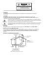
1
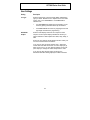
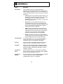
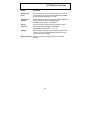
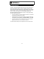
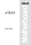
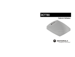
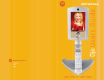
CAUTION
RISK OF ELECTRIC SHOCK
CAUTION: TO REDUCE THE RISK OF ELECTRIC SHOCK,
DO NOT REMOVE COVER (OR BACK).
NO USER-SERVICEABLE PARTS INSIDE.
REFER SERVICING TO QUALIFIED SERVICE PERSONNEL.
Graphical symbols and supplemental warning marking locations on bottom of terminal.
WARNING
TO PREVENT FIRE OR SHOCK HAZARD, DO NOT EXPOSE THIS APPLIANCE TO RAIN OR
MOISTURE.
CAUTION
TO PREVENT ELECTRICAL SHOCK, DO NOT USE THIS (POLARIZED) PLUG WITH AN
EXTENSION CORD, RECEPTACLE, OR OTHER OUTLET UNLESS THE BLADES CAN BE FULLY
INSERTED TO PREVENT BLADE EXPOSURE.
The lightning flash with arrowhead symbol, within an equilateral triangle, is intended to alert the
user to the presence of uninsulated “dangerous voltage” within the product’s enclosure that may
be of sufficient magnitude to constitute a risk of electric shock to persons.
The exclamation point, within an equilateral triangle, is intended to alert the user to the presence
of important operating and maintenance (servicing) instructions in the literature accompanying
the appliance.
REPAIRS
If you find the unit in need of repair, call Motorola Support at 1-866-668-2271 or 1-866-MOT-BCS1.
NOTE TO CATV SYSTEM INSTALLER
This reminder is provided to call the CATV system installer’s attention to Article 820-40 of the NEC that
provides guidelines for proper grounding and, in particular, specifies that the cable ground shall be
connected to the grounding system of the building, as close as possible to the point of cable entry as
practical.
EXAMPLE OF ANTENNA GROUNDING
Electric service Ground
equipment
clamp
Antenna lead
in wire
Antenna
discharge unit
(NEC Section 810-20)
Grounding
clamps
Grounding conductors
(NEC Section 810-21)
Power service grounding
electrode system
(NEC Article 250, Part H)
NEC=NATIONAL ELECTRICAL CODE
IMPORTANT SAFETY INSTRUCTIONS
1
Read instructions
All the safety and operating instructions should be read before the appliance is operated.
2
Retain instructions
The safety and operating instructions should be retained for future reference.
3
Heed warnings
All warnings on the appliance and in the operating instructions should be adhered to.
4
Follow instructions
All operating and use instructions should be followed.
5
Cleaning
Unplug this product from the wall outlet before cleaning. Do not use liquid cleaners or aerosol
cleaners. Use a damp cloth for cleaning.
6
Attachments
Do not use attachments not recommended as they may cause hazard.
7
Water and moisture
Do not use this equipment near water; for example, near a bathtub, wash bowl, kitchen sink, or
laundry-tub, in a wet basement, or near a swimming pool, and the like.
8
Accessories
Do not place this product on an unstable cart, stand, tripod, bracket, or table. The product may fall
causing serious injury and serious damage to the appliance. Use only with a cart, stand, tripod,
bracket, or table recommended by the manufacturer, or sold with the equipment. Any mounting of
the appliance should follow the manufacturer’s instructions, and should use a mounting accessory
recommended by the manufacturer.
9
Ventilation
Slots and openings in the cabinet are provided for ventilation and to ensure reliable operation of
the equipment and to protect it from overheating. The openings should never be blocked by
placing the product on a bed, sofa, rug, or similar surface. Equipment should never be placed near
or over a radiator or heat register, or in a built-in installation such as a bookcase or rack unless
proper ventilation is provided.
10
Power sources
This product should be operated only from the type of power sources indicated on the marking
label. If you are not sure of the type of power supplied to your home, consult your local power
company. For equipment intended to operate from battery power, or other sources, refer to the
operating instructions.
11
Ground or polarization
This equipment may be equipped with a polarized alternating-current line plug (a plug having one
blade wider than the other). This plug will fit into the power outlet only one way. This is a safety
feature. If you are unable to insert the plug fully into the outlet, try reversing the plug. If the plug
should still fail to fit, contact your electrician to replace your obsolete outlet. Do not defeat the
safety purpose of the polarized plug.
12
Alternate warnings
This equipment may be equipped with a 3-wire grounding-type plug, a plug having a third
(grounding) pin. This pin will only fit into a grounding-type power outlet. This is a safety feature. If
you are unable to insert the plug into the outlet, contact your electrician to replace your obsolete
outlet. Do not defeat the safety purpose of the grounding-type plug.
13
Power cord protection
Power supply cords should be routed so that they are not likely to be walked on or pinched by
items placed upon or against them, paying particular attention to cords at plugs, convenience
receptacles, and the point where they exit from the appliance
IMPORTANT SAFETY INSTRUCTIONS
14
Outdoor Antenna Grounding
If an outside antenna or cable system is connected to the equipment, be sure the antenna or cable
system is grounded as to provide some protection against voltage surges and built-up static
charges.
15
Lightning
For added protection for this equipment during a lightning storm, or when it is left unattended and
unused for long periods of time, unplug it from the wall outlet and disconnect the antenna or cable
system. This will prevent damage to the video product due to lightning and power line surges.
16
Power lines
An outside antenna system should not be located in the vicinity of overhead power lines or where it
can fall into such power lines or circuits. When installing an outside antenna system, extreme care
should be taken to keep from touching such power lines or circuits, as contact with them may be
fatal.
17
Overloading
Do not overload wall outlets and extension cords as this can result in a risk of fire or electrical
shock.
18
Object and liquid entry
Never push objects of any kind into this equipment through openings, as they may touch
dangerous voltage points or short-out parts that could result in a fire or electrical shock. Never spill
liquid of any kind on
the product.
19
Servicing
Do not attempt to service this equipment yourself, as opening or removing covers may expose you
to dangerous voltage or other hazards, refer all servicing to qualified service personnel.
20
Damage requiring service
Unplug this equipment from the wall outlet and refer servicing to qualified service personnel under
the following conditions:
a When the power supply cord or plug is damaged.
b If the equipment has been exposed to rain or water.
c If liquid has been spilled, or objects have fallen into the equipment.
d If the equipment does not operate normally by following the operating instructions. Adjust only
those controls that are covered by the operating instructions, as an improper adjustment of
other controls may result in damage and will often require extensive work by a qualified
technician to restore the equipment to its normal operation.
e If the equipment has been dropped or cabinet has been damaged.
f
When the equipment exhibits a distinct change in performance, indicating a need for service.
21
Replacement parts
When replacement parts are required, be sure the service technician has used replacement parts
specified by the manufacturer or have the same characteristics as the original part. Unauthorized
substitutions may result in fire, electric shock, or other hazards.
22
Safety check
Upon completion of any service or repairs to this video product, ask the service technician to
perform safety checks to determine that the product is in proper operational condition.
IMPORTANT SAFETY INSTRUCTIONS
23
Battery usage
Notwithstanding any information provided by Motorola in this manual regarding the use of
batteries, the end user assumes all responsibility and liability to use and dispose of batteries in
accordance with all applicable laws, rules and regulations. Motorola will not be liable to anyone for
the end user's failure to use and/or dispose of batteries in the proper manner and in accordance
with such laws, rules and regulations, or for any defect contained in batteries which may cause
injury damage to persons or property.
24
Heat
This product should be situated away from heat sources such as radiators, heat registers, stoves,
or other products (including amplifiers) that produce heat.
Regulatory Information
Federal Communications Commission Radio and Television Interface Statement for a Class ‘B’
Device
This equipment has been tested and found to comply with the limits for a Class B digital device,
pursuant to part 15 of the FCC Rules. These limits are designed to provide reasonable protection
against harmful interference in the residential installation. This equipment generates, uses and can
radiate radio frequency energy and, if not installed and used in accordance with the instructions, may
cause harmful interference to radio communications. However, there is no guarantee that interference
will not occur in a particular installation.
If the equipment does cause harmful interference to radio or television reception, which can be
determined by turning the equipment off and on, the user is encouraged to try to correct the interference
by one of the following measures:
•
Increase the separation between the equipment and the affected receiver
•
Connect the equipment on a circuit different from the one the receiver is on
•
Ensure that the cover plate for the security card is secured and tight
Changes or modification not expressly approved by the party responsible for compliance could void the
user’s authority to operate the equipment.
Declaration of Conformity
According to 47 CFR, Parts 2 and 15 for Class B Personal Computers and Peripherals; and/or CPU
Boards and Power Supplies used with Class B Personal Computers, Motorola, Inc., 6450 Sequence
Drive, San Diego, CA 92121, 1-800-225-9446, declares under sole responsibility that the product
identifies with 47 CFR Part 2 and 15 of the FCC Rules as a Class B digital device. Each product
marketed is identical to the representative unit tested and found to be compliant with the standards.
Records maintained continue to reflect the equipment being produced can be expected to be within the
variation accepted, due to quantity production and testing on a statistical basis as required by 47 CFR
2.909. Operation is subject to the following condition: This device must accept any interference received,
including interference that may cause undesired operation. The above named party is responsible for
ensuring that the equipment complies with the standards of 47 CFR, Paragraphs 15.101 to 15.109. The
Class B digital apparatus meets all requirements of the Canadian Interface Causing Equipment
Regulations.
Software License
IMPORTANT: PLEASE READ THIS SOFTWARE LICENSE (“LICENSE”) CAREFULLY BEFORE YOU
USE ANY SOFTWARE, FIRMWARE AND RELATED DOCUMENTATION (“SOFTWARE”) PROVIDED
WITH MOTOROLA’S DIGITAL CABLE RECEIVER OR HOME THEATER SYSTEM (EACH SHALL BE
REFERRED TO IN THIS LICENSE AS A “RECEIVER”). BY USING THE RECEIVER AND/OR USING
ANY OF THE SOFTWARE, YOU INDICATE YOUR ACCEPTANCE OF EACH OF THE TERMS OF
THIS LICENSE. UPON ACCEPTANCE, THIS LICENSE WILL BE A LEGALLY BINDING AGREEMENT
BETWEEN YOU AND MOTOROLA. THE TERMS OF THIS LICENSE APPLY TO YOU AND TO ANY
SUBSEQUENT USER OF THIS SOFTWARE.
IF YOU DO NOT AGREE TO ALL OF THE TERMS OF THIS LICENSE (I) DO NOT USE THE
SOFTWARE AND (II) RETURN THE RECEIVER AND THE SOFTWARE (COLLECTIVELY,
“PRODUCT”), INCLUDING ALL COMPONENTS, DOCUMENTATION AND ANY OTHER MATERIALS
PROVIDED WITH THE PRODUCT, TO YOUR POINT OF PURCHASE OR SERVICE PROVIDER, AS
THE CASE MAY BE, FOR A FULL REFUND.
The Software includes associated media, any printed materials, and any “on-line” or electronic
documentation. Software provided by third parties may be subject to separate end-user license
agreements from the manufacturers of such Software. The Software is never sold. Motorola licenses the
Software to the original customer and to any subsequent licensee for personal use only on the terms of
this License. Motorola and its third party licensors retain the ownership of the Software.
SOFTWARE LICENSE
You may:
USE the Software only in connection with the operation of the Product.
TRANSFER the Software (including all component parts and printed materials) permanently to another
person, but only if the person agrees to accept all of the terms of this License. If you transfer the
Software, you must at the same time transfer the Product and all copies of the Software (if applicable) to
the same person or destroy any copies not transferred.
TERMINATE this License by destroying the original and all copies of the Software (if applicable) in
whatever form.
You may not:
(1) Loan, distribute, rent, lease, give, sublicense or otherwise transfer the Software, in whole or in part,
to any other person, except as permitted under the TRANSFER paragraph above. (2) Copy or translate
the User Guide included with the Software, other than for personal use. (3) Copy, alter, translate,
decompile, disassemble or reverse engineer the Software, including but not limited to, modifying the
Software to make it operate on non-compatible hardware. (4) Remove, alter or cause not to be
displayed, any copyright notices or startup message contained in the Software programs or
documentation. (5) Export the Software or the Product components in violation of any United States
export laws.
The Product is not designed or intended for use in on-line control of aircraft, air traffic, aircraft navigation
or aircraft communications; or in design, construction, operation or maintenance of any nuclear facility.
MOTOROLA AND ITS THIRD PARTY LICENSORS DISCLAIM ANY EXPRESS OR IMPLIED
WARRANTY OF FITNESS FOR SUCH USES. YOU REPRESENT AND WARRANT THAT YOU SHALL
NOT USE THE PRODUCT FOR SUCH PURPOSES.
Title to this Software, including the ownership of all copyrights, mask work rights, patents, trademarks
and all other intellectual property rights subsisting in the foregoing, and all adaptations to and
modifications of the foregoing shall at all times remain with Motorola and its third party licensors.
Motorola retains all rights not expressly licensed under this License. The Software, including any
images, graphics, photographs, animation, video, audio, music and text incorporated therein is owned by
Motorola or its third party licensors and is protected by United States copyright laws and international
treaty provisions. Except as otherwise expressly provided in this License, the copying, reproduction,
distribution or preparation of derivative works of the Software, any portion of the Product or the
documentation is strictly prohibited by such laws and treaty provisions. Nothing in this License
constitutes a waiver of Motorola’s rights under United States copyright law.
This License and your rights regarding any matter it addresses are governed by the laws of the
Commonwealth of Pennsylvania, without reference to conflict of laws principles. THIS LICENSE SHALL
TERMINATE AUTOMATICALLY if you fail to comply with the terms of this License.
Motorola is not responsible for any third party software that is provided as a bundled application, or
otherwise, with the Software or that is downloaded to, or otherwise installed on, the Product.
U.S. GOVERNMENT RESTRICTED RIGHTS
The Product and documentation is provided with RESTRICTED RIGHTS. The use, duplication or
disclosure by the Government is subject to restrictions as set forth in subdivision (c)(1)(ii) of The Rights
in Technical Data and Computer Software clause at 52.227-7013. The contractor/manufacturer is
Motorola, Inc., Broadband Communications Sector, 101 Tournament Drive, Horsham, PA 19044.
Canadian Compliance
This Class B digital apparatus meets all requirements of the Canadian Interference-Causing
Equipment Regulations. Cet appareil numérique de la classe B respects toutes les exigences du
Règlement sur le matériel brouilleur du Canada.
Contact Us
For technical support of your Receiver, call Motorola Support at 1-866-668-2271 or 1-866-MOT-BCS1.
For questions about your cable TV service, call your local cable service provider.
For Motorola consumer cable products, education, and support:
http://www.motorola.com/broadband
___________________________________________________________________________________
Copyright © 2004 Motorola, Inc.
All rights reserved. No part of this publication may be reproduced in any form or by any means or used
to make any derivative work (such as translation, transformation or adaptation) without written
permission from Motorola, Inc.
Motorola reserves the right to revise this publication and to make changes in content from time to time
without obligation on the part of Motorola to provide notification of such revision or change. Motorola
provides this guide without warranty of any kind, either implied or expressed, including but not limited to,
the implied warranties of merchantability and fitness for a particular purpose. Motorola may make
improvements or changes in the product(s) described in this manual at any time.
MOTOROLA and the Stylized M Logo are registered in the US Patent & Trademark Office. Dolby Digital
manufactured under license from Dolby Laboratories Licensing Corporation. Dolby, Dolby Digital,
ProLogic and the double-D symbol are registered trademarks of Dolby Laboratories Licensing
Corporation. All other product or service names are the property of their respective owners.
© Motorola, Inc. 2004
DCT6400 Series User Guide
CONTENTS
Introduction ............................................................................................. 3
Operation ................................................................................................. 6
Turning Power On and Off ............................................................... 6
Changing Channels .......................................................................... 6
Adjusting the Volume....................................................................... 6
Interactive Program Guide............................................................... 6
Digital Video Recorder (DVR)................................................................. 7
What is DVR? .................................................................................... 7
Optimizing Your DCT* For High Definition TV ..................................... 9
User Settings................................................................................... 11
On-Screen Graphics ............................................................................. 14
Connecting Your DCT* ......................................................................... 15
Video Options ................................................................................. 16
Important Safety Considerations .................................................. 17
Connecting Your DCT* to a HDTV – Video Only ................................ 18
Connecting Your DCT* to a HDTV – Audio Only................................ 20
Connecting Your DCT* to an A/V Receiver – Audio Only ................. 22
Connecting Your DCT* to a Stereo TV ................................................ 24
Connecting Your DCT* to a Stereo TV and Stereo VCR.................... 26
Connecting Your DCT* to an A/V Receiver, TV, and VCR ................. 28
1
Recording Your Connections .............................................................. 30
Data Devices .......................................................................................... 31
Data Features .................................................................................. 31
Troubleshooting .................................................................................... 32
2
DCT6400 Series User Guide
INTRODUCTION
Welcome and congratulations on receiving a Motorola DCT6400 Series
High Definition Dual Tuner DVR Cable Receiver, one of the most
advanced interactive digital cable receivers available today. With the
DCT*, Motorola has merged the extraordinary features of digital cable –
the seemingly endless programming options, interactive program guides,
Video on Demand (VOD), and commercial free, CD quality music – with
the flexibility of a dual tuner digital video recorder (DVR) and the
incredible picture quality and sound of high definition TV (HDTV).
The DCT* includes an “Entertainment Package” that enables a direct
digital connection to consumer audio and video devices through
1394-DTV and DVI interfaces. The DCT* is fully equipped with a factory
installed hard drive for hours of DVR functionality, which includes the
capability of recording high definition (HD) programs and watch and
record functionality.
This User Guide introduces you to the basic features of the DCT*,
outlines important safeguards, and provides several options for
integrating this component into your current entertainment system.
Please take a few moments to read through this User Guide as the
configuration diagrams, on-screen menu description, and troubleshooting
section will help you make the most of your home entertainment
experience.
To determine which features of digital cable are provided in your service
area, please check with your local cable operator. They will be happy to
provide instructions for these optional services.
In this manual, DCT* refers to the DCT6400 Series of High Definition
Cable Receivers: the DCT6412 and DCT6416.
3
Message Indicator
Lights when a message is waiting
POWER switch
Turns the DCT* on or off
FRONT PANEL
MENU switch
Displays the menu area
INFO switch
Displays current channel and program information
C URSOR
INFO
MSGS.
MENU
ON
POW ER
USB
VIDEO IN
L AUDIO IN R
Dual Tuner DVR / HDTV Capable
CURSOR
POWER
indicator
Moves cursor around program
guide and menu screens
Lights to indicate
DCT* is on
AUDIO IN (L/R)*
Connects to a CD player or stereo tuner
USB*
Connects to
support devices
VIDEO IN*
Connects to baseband video output of a
VCR, camcorder, or other video device
AUDIO IN (R/L)*
Connects to a CD player or stereo tuner
CABLE IN
Connects to cable signal
from your service provider
ETHERNET*
DVI
Supports PC
networking
Connects DCT*
to a high-definition TV
ETHERNET
R
DVI-D OUT
IR
CABLE
IN
AUDIO OUT
USB
TV
Pass Card
IR
Enables DCT* to control a VCR
while recording a selected program.
(Not supported by all program guides.)
USB*
Connects to support devices
AUDIO OUT (R/L)
Connects to audio input of a stereo receiver
4
AUDIO IN
L
DCT6400 Series User Guide
RECORD Indicator
Lights to indicate the DVR is recording
SELECT switch
Selects menu options
GUIDE switch
Displays the program guide
OPTION switch
Reserved for future use
CH ANNEL
OPTION
RECORD
GUIDE
SMART C ARD
REMOTE
SELEC T
REMOTE
indicator
SMART
CARD*
Lights to indicate
remote control
is in use
Supports electronic commerce using a
Smart Card
Display
CHANNEL
Displays channel number
and time of day
SPDIF
Scrolls down or
up through the
channels
®
Provides Dolby Digital 5.1 audio or PCM audio
VIDEO IN*
BACK PANEL
Connects to baseband video output from
a VCR, camcorder, or other video device
VIDEO OUT
AC Switched Outlet
Delivers video to an external
device, such as a TV or VCR
L
SPDIF
IN
VIDEO
OUT
IEEE 1394
S-VIDEO
Y
Connect AC power cord from
another device, such as a TV or VCR
Pb
Pr
OPTICAL
SPDIF
IEEE 1394
Y Pb Pr
Delivers component video
Connects to audio and video devices
OPTICAL SPDIF
®
Provides Dolby Digital 5.1 audio or PCM audio
S-Video
Connect to S-Video input of TV or VCR
*Your DCT* may not support all of the inputs and outputs shown.
5
OPERATION
Turning Power On and Off
Press POWER on the front panel to turn the DCT* on or off. When using
the remote control, be sure it is in cable mode by pressing CABLE before
pressing POWER.
Changing Channels
You can change channels in two ways:
•
Press CHANNEL ! or " on the front panel of the DCT*, or
press CHANNEL + or - on the remote control to step through the
channel selection.
•
Enter the number of the channel you wish to view using the number
keys on the remote control.
Adjusting the Volume
Press VOLUME + or – on the remote control to adjust the volume. When
you adjust the volume, the volume scale is displayed on the screen.
Press MUTE on the remote control to turn the sound off and on again.
For best audio quality, use the remote control to set the DCT* to
approximately ¾ of the maximum volume level and then adjust the audio
levels on external devices such as your TV or A/V Receiver.
Interactive Program Guide
The interactive program guide displays information about TV programs
and enables you to access features such as Parental Control or
Pay-Per-View. Interactive program guides can vary with each cable
service provider. Refer to the interactive program guide instruction
manual for detailed instructions.
6
DCT6400 Series User Guide
DIGITAL VIDEO RECORDER (DVR)
The DCT* is equipped with an internal hard drive for DVR functionality,
which provides the ability to record both standard definition TV (SDTV)
and high definition TV (HDTV) programs. Storage time depends on the
video format and the bit rate at which it is received.
What is DVR?
DVR stands for Digital Video Recorder. A standard VCR records and
plays analog video. DVR records and plays digital video. Unlike an
analog cassette tape, the DCT*'s hard drive allows recording and
playback to occur simultaneously.
DVR offers the ability to control your viewing experience by pausing
(time shifting) live TV and providing trick playback modes (pause, fast
forward, slow forward, fast rewind, slow rewind). You may experience a
slight delay between time shifted and live TV.
With the DCT*, you can:
Record Programming
Record hours of TV programming. The total hours of recorded content
will vary based on the storage capacity of your DCT* and type of content
(digital, analog, or HD) being recorded.
Maintain a Personal Program Library
Maintain a personal library of recorded programming, accessed by using
the electronic program guide (EPG).
Control Live TV
Pause, rewind, and fast-forward live TV.
Simultaneously Watch Two Programs
Watch two programs and easily switch between them using the SWAP
key on your remote control. (Dependent upon program guide support.)
Simultaneous Watch and Record
Record one program in the background while viewing another live
broadcast at the same time.
7
Simultaneously Record Two Shows
Record two programs from two different channels at the same time.
Simultaneously Record Two Shows and Watch a Recorded Program
Watch a program recorded on your DCT* while recording up to two other
programs at the same time. You can also easily switch viewing the
pre-recorded program and either of the programs you’re recording.
8
DCT6400 Series User Guide
OPTIMIZING YOUR DCT* FOR HIGH DEFINITION TV
The DCT* enables you to view HD programming. HDTV provides up to
twice the color resolution and up to six times the sharpness of standard
definition TV.
The Motorola DCT* delivers high-quality video for HDTVs using the
YPbPr (component), DVI-D, and IEEE 1394 connectors. This section
describes how to use the on-screen display to set your DCT* to
automatically optimize both standard and HD video based on your HDTV
and personal preferences.
If you use the IEEE 1394 connector, no adjustments to your settings are
required.
If you have a TV with a DVI connection, be sure that the TV is on and
connected to the DVI-D OUT connector of the DCT* before adjusting the
settings.
You can use your on-screen menu to configure your HD settings for TV
type, DVI and/or YPbPr video output, and closed captioning.
To access your HD settings:
1
Ensure that your DCT* is plugged into a power outlet and is turned
off.
9
2
Press the MENU key on the front panel. If your TV is on, the
on-screen display menu appears listing the settings you can
configure.
DVI/YPbPr OUTPUT
RESTORE DEFAULTS
Use your remote control or the cursor keys on the front panel to navigate
the on-screen display:
•
Press the ▲ and ▼ keys to highlight the setting you wish to
change. Press the ► key to select an option for that setting.
•
To exit the setting and move to another setting, use the ▲ and ▼
keys.
•
To exit the menu and save your settings, press the POWER or MENU
key.
The HD settings are described in the table on the following pages.
The DVI/YPbPr OUTPUT setting is displayed as YPbPr OUTPUT if you
are not using the DVI video connection. The user settings will also be
displayed on the front panel display whether your TV is off or on.
If the on-screen display menu does not appear on your HDTV screen,
your TV may not support the default video output setting. Use the DCT*
front panel display to view and change your settings.
10
DCT6400 Series User Guide
User Settings
Setting
Description
TV Type
Sets the aspect ratio. The front panel display indicates the
type you select. Defaults to 16:9. Options are 16:9 for wide
screen TVs or 4:3 LETTERBOX or 4:3 PAN/SCAN for
standard TVs:
DVI/YPbPr
Output
•
4:3 LETTERBOX fits widescreen programming on the
screen by placing black bars at the top and bottom.
•
4:3 PAN/SCAN fills the screen by cropping the left and
right edges of widescreen programming.
Sets the video display format for the component video
outputs. The front panel display indicates the format you
select. Defaults to 1080i. Options are 1080i, 720p, 480p, or
480i.
Some TVs only support certain display formats. Check your
TV user manual for more information.
If you are not using an HDTV with the DCT*, selecting a
format other than 480i causes the on-screen display to go
blank. If this occurs, you can view the settings on the front
panel display to change the YPbPr Output back to 480i.
If you are not using the DVI video connection, the
DVI/YPbPr OUTPUT setting displays as YPbPr OUTPUT.
11
Setting
Description
4:3 Override
Sets the display format for 4:3 standard-definition
programming. If the YPrPb Output is set to 1080i, 720p, or
480p, this setting defaults to 480i. If the YPrPb Output is set
to 480i, this setting defaults to OFF and cannot be changed.
Options are:
•
OFF displays non-high-definition programs having a 4:3
aspect ratio in wide screen format. On an HDTV, black
bars display on the left and right of the picture.
Selecting OFF for a 4:3 TV may result in a small picture
with black bars around it.
•
480i displays non-high-definition programs in their
original 480i format. Some TVs cannot display 480i
format on their component video inputs (YPbPr). Check
the TV user manual for more information. Graphics
overlaying the video are displayed.
•
480p converts non-high-definition TV programs to a
higher-quality 480p format. Some TVs cannot display
480p format on their component video inputs (YPbPr).
Check the TV user manual for more information.
Graphics overlaying the video are not displayed.
•
Stretch automatically stretches all standard definition
programming to fill your widescreen display. Stretch can
only be selected if you have TV Type set to 16:9.
Closed Caption
Turns closed captions off or on. The front panel display
indicates the status of the closed captions. Defaults to
DISABLED. Options are ENABLED or DISABLED.
Pen Size
Sets the font size for closed captions. Defaults to AUTO.
Options are AUTO, STANDARD, LARGE, or SMALL.
Font Style
Sets the font style for closed captions. Defaults to AUTO.
Options are AUTO, MONO SERIF, PROPORTION SERIF,
MONO NO SERIF, PROPORTION NO SERIF, CASUAL,
CURSIVE, or SMALL.
Foreground
Color
Sets the foreground color for closed captions. Defaults to
AUTO. Options are AUTO, WHITE, BLACK, RED, GREEN,
BLUE, YELLOW, MAGENTA, or CYAN.
Foreground
Opacity
Sets the opacity of the closed captions foreground. Defaults
to AUTO. Options are AUTO, TRANSPARENT,
TRANSLUCENT, SOLID, or FLASHING.
12
DCT6400 Series User Guide
Setting
Description
Background
Color
Sets the background color for closed captions. Defaults to
AUTO. Options are AUTO, WHITE, BLACK, RED, GREEN,
BLUE, YELLOW, MAGENTA, or CYAN.
Background
Opacity
Sets the background opacity for closed captions. Defaults to
AUTO. Options are AUTO, TRANSPARENT,
TRANSLUCENT, SOLID, or FLASHING.
Service
Selection
Sets the service for closed captions. Defaults to AUTO.
Options are AUTO, PRIMARY LANGUAGE,
SECONDARY LANGUAGE, 3, 4, 5, or 6.
Settings
Sets the default settings for closed captions (AUTO) or the
settings you have configured (USER). Defaults to AUTO.
Options are AUTO or USER.
Restore Defaults
Resets the on-screen display options to their default
settings.
13
ON-SCREEN GRAPHICS
The DCT* can generate graphics that overlay the video programming or
fill the entire television screen. Common examples include on-screen
menus (such as the User Setting menu), closed captions, and interactive
program guides. The DCT* overlays these graphics whenever you open
a menu, enable closed captions, or scroll through a program grid.
On-screen graphics are not available on all DCT* YPbPr output setting
and video output combinations:
•
On-screen graphics are always available if your DCT* is connected
through the HD outputs (DVI or YPbPr)
•
Standard definition connections (S-Video or composite Video) will
only display on-screen graphics if the YPbPr Output is set to 480i
•
On-screen graphics will not be displayed when you are using the
IEEE 1394 connection on the rear panel of the DCT*
The YPbPr Output setting can be configured from the on-screen menu.
14
DCT6400 Series User Guide
CONNECTING YOUR DCT*
This section describes how to connect the DCT* to your home
entertainment system.
Instructions and diagrams are included for the following connections to
the DCT*:
•
High Definition Television (HDTV)
•
A/V Receiver – Audio
•
Stereo TV
•
Stereo TV and Stereo VCR
•
A/V Receiver, TV, and VCR
In this manual, DCT* refers to the DCT6400 Series of High Definition
Cable Receivers: DCT6412 and DCT6416.
Before you move or change components on your entertainment system,
review the following:
•
For basic cable connections, use 75-ohm coaxial cables equipped
with F-type connectors.
•
Disconnect power from the DCT* before connecting or changing
cable connections.
For information on connecting for HDTV, see “Video Options” on the next
page.
CAUTION!
Do not place anything on top of the DCT*, especially other home
entertainment components. Be sure to provide adequate ventilation to
prevent overheating.
15
Video Connection Options
The DCT* offers five different video connection options. Component
video, DVI, and IEEE 1394 allow you to view both HD and standard TV
programming. Composite video and RF coaxial connections allow you to
view only standard definition TV programming.
To determine whether your TV features component video, DVI,
IEEE 1394, S-Video, or composite video, check the manual supplied with
your TV.
Use the guidelines below to determine the best video connection for your
home entertainment system:
•
Component video (YPbPr) – HDTV and SDTV
The YPbPr connectors on your DCT* provide HD component video.
Component is the most widely supported HD video connection.
•
S-Video – SDTV
If component video connections are not available on your TV, use
the S-Video connection.
•
Video (also referred to as composite video) – SDTV
If S-Video is not available, use the composite video (VIDEO)
connection.
•
RF Input – SDTV
If your TV only has an RF input, you can connect to the DCT* using
a RF Modulator, which can be purchased at most electronics
stores.
•
DVI or IEEE 1394 – HDTV and SDTV
DVI and IEEE 1394 offer higher quality HD video than component
video.
If your TV has a DVI input, connect to the DVI-D connections on
your DCT* instead of the IEEE 1394 connection.
The IEEE 1394 is a video and audio connection, so no audio
connections are required if you are using the IEEE 1394
connection and you plan to use your TV’s speakers as the primary
audio source.
HD video can only be viewed with DVI, IEEE 1394, or component video
connections.
16
DCT6400 Series User Guide
Important Safety Considerations
V E N T I L AT E
2 inch space
2
2
inch
INFO
OPTION
P
MSGS.
RECORD
MENU
GUIDE
ON
MUTE
POWER
USB
VIDEO IN
inch
C HANNEL
CURSOR
SMARTCARD
REMOTE
SELEC T
L AUDIO IN R
Dual Tuner DVR / HDTV Capable
Follow these important safety guidelines when positioning and
connecting the DCT*:
•
Position the DCT* with at least 2 inches of space above and on all
sides
•
Do not block the slots and openings in the DCT*
•
Do not place anything on top of the DCT*
•
Do not position the DCT* in an enclosed space that would restrict
airflow around the unit
•
Do not position the DCT* near any external heat source that could
raise the temperature around the unit. Do not place the DCT* on
top of another heat-producing electronic device.
•
Allow for adequate ventilation around the DCT* to maintain normal
operating temperature. Do not place the DCT* in a sealed
enclosure without providing for adequate airflow.
•
Do not plug the AC power cord into a switched power outlet.
17
CONNECTING YOUR DCT* TO A HDTV – VIDEO ONLY
DVI
connection
Component video
connection
IEEE 1394
connection
DCT6400 Series
ETHERNET
R
AUDIO IN
VIDEO
OUT
IEEE 1394
S-VIDEO
AUDIO OUT
TV
Pass Card
USB
Y
Pb
Pr
OPTICAL
SPDIF
Cable in
Either / or
HDTV
Component
Video Input
CABLE/
ANTENNA IN
IN
DVI-D OUT
IR
CABLE
IN
DVI-HDTV
L SPDIF
Y
Pb
IEEE 1394
Pr
18
DCT6400 Series User Guide
Connecting HDTV – Video Only
Component Video (YPbPr)
1
Connect an RF coaxial cable to the cable wall outlet and the
CABLE IN connector on the DCT*.
2
Connect the component video cables to the Y, Pb, and Pr
connectors on your HDTV and DCT*.
This connection supports only the high-definition video connection
between the DCT* and the HDTV. To connect the audio connections for
your HDTV, proceed to the following page. To connect your audio
connections for an A/V receiver, go to “Connecting Your DCT* to an A/V
Receiver – Audio Only.”
IEEE 1394
If your HDTV has an IEEE 1394 connector, you can use the IEEE 1394
for both your video and audio connection:
•
Connect an IEEE 1394 cable to the IEEE 1394 connector on your
HDTV and DCT*.
On-screen graphics will not be displayed when you are using the
IEEE 1394 connection on the rear panel of the DCT*.
DVI
If your TV has a DVI input, use the DVI connection for your video:
•
Connect a DVI cable to the DVI-D OUT connector on the DCT* and
the DVI-HDTV connector on your TV.
This connection supports only the high-definition video connection
between the DCT* and the HDTV. To connect the audio connections for
your HDTV, proceed to the following page. To connect your audio
connections for an A/V receiver, go to “Connecting Your DCT* to an A/V
Receiver – Audio Only.”
For information on configuring your DCT* settings, see “Optimizing Your
DCT* for High Definition TV.”
19
CONNECTING YOUR DCT* TO A HDTV – AUDIO ONLY
Audio
connection
Optical
connection
Digital audio
connection
DCT6400 Series
ETHERNET
R
AUDIO IN
VIDEO
IN
OUT
IEEE 1394
S-VIDEO
AUDIO OUT
TV
Pass Card
USB
Y
Pb
Pr
OPTICAL
SPDIF
Optional
Optional
HDTV
INPUT
DIGITAL INPUT
COAX
OPTICAL
SPDIF
SPDIF
DVI-D OUT
IR
CABLE
IN
CABLE/
ANTENNA IN
L
AUDIO LEFT
AUDIO RIGHT
20
DCT6400 Series User Guide
Connecting HDTV – Audio Only
•
Connect the stereo audio cable to the AUDIO R and L connectors on
the DCT* and the AUDIO LEFT and AUDIO RIGHT connectors on the
HDTV.
If your equipment supports it:
•
The optical (OPTICAL SPDIF) or coaxial digital (SPDIF) audio outputs
may be used in place of the stereo audio outputs (AUDIO R and L). In
most cases these outputs offer a higher level of audio quality,
including support for 5.1 Surround Sound.
For information on configuring your DCT* settings, see “Optimizing Your
DCT* for High Definition TV.”
21
CONNECTING YOUR DCT* TO AN A/V RECEIVER – AUDIO ONLY
Audio
connection
Digital audio
connection
Optical
connection
DCT6400 Series
ETHERNET
R
L SPDIF
AUDIO IN
VIDEO
IN
OUT
DVI-D OUT
IR
CABLE
IN
USB
Y
Pb
Pr
TV
Pass Card
OPTICAL
SPDIF
Either / or
AUDIO
R
L
VIDEO
VIDEO
S-VIDEO
DIGITAL INPUT
COAX
DVD
CABLE/TV
OPTICAL
VIDEO 2
TV/MONITOR
OUTPUT
SPEAKER
CONNECTORS
IN
VCR
IEEE 1394
S-VIDEO
AUDIO OUT
VIDEO S-VIDEO
OUT
A/V receiver
22
DCT6400 Series User Guide
Connecting an A/V Receiver – Audio Only
There are three options available for audio connections to your A/V
receiver:
•
Optical (OPTICAL SPDIF)
•
Coaxial (SPDIF)
•
Stereo audio (AUDIO R and L)
If your equipment supports it, the optical (OPTICAL SPDIF) or coaxial
(SPDIF) audio outputs may be used in place of the stereo audio outputs
(AUDIO R and L). In most cases these outputs offer a higher level of audio
quality, including support for 5.1 surround sound.
•
Optical SPDIF: Connect the optical SPDIF cable to the OPTICAL
on the DCT* and the OPTICAL connector on the A/V
receiver.
•
SPDIF: Connect the digital audio cable to the SPDIF connector on
the DCT* and the DIGITAL INPUT COAX connector on the A/V
receiver.
•
Stereo audio: Connect the stereo audio cable to the AUDIO R and L
connectors on the DCT* and the AUDIO LEFT and AUDIO RIGHT
connectors on the A/V receiver.
SPDIF connector
For information on configuring your DCT* settings, see “Optimizing Your
DCT* for High Definition TV.”
23
CONNECTING YOUR DCT* TO A STEREO TV
RF (75 ohm)
connection
S-Video
connection
Video
connection
Audio
connection
DCT6400 Series
ETHERNET
R
AUDIO IN
L
SPDIF
VIDEO
IN
OUT
DVI-D OUT
IR
CABLE
IN
USB
IEEE 1394
S-VIDEO
AUDIO OUT
TV
Pass Card
Y
Pb
Pr
OPTICAL
SPDIF
Cable in
Either / or
Stereo TV
Either / or
INPUT
S-VIDEO
VIDEO
CABLE/
ANTENNA IN
AUDIO LEFT
AUDIO RIGHT
24
DCT6400 Series User Guide
Connecting a Stereo TV
1
Connect an RF coaxial cable to the cable wall outlet and the
CABLE IN connector on the DCT*.
2
Connect the stereo audio cable to the AUDIO R and L connectors on
the DCT* and the AUDIO LEFT and AUDIO RIGHT connectors on the
stereo TV.
Connect a video cable to the VIDEO OUT connector on the DCT* and
the INPUT VIDEO on the TV or an S-video cable to the S-VIDEO
connectors on the DCT* and the TV.
This video connection method does not support HD video. For more
information, see “Connecting your DCT* to an HDTV – Video Only” on
page 18.
25
CONNECTING YOUR DCT* TO A STEREO TV AND STEREO VCR
RF (75 ohm)
connection
Video
connection
Audio
connection
DCT6400 Series
ETHERNET
R
AUDIO IN
L SPDIF
IN
VIDEO
OUT
DVI-D OUT
IR
CABLE
IN
USB
IEEE 1394
S-VIDEO
AUDIO OUT
Y
Pb
Pr
TV
Pass Card
OPTICAL
SPDIF
Cable in
Stereo VCR
Stereo TV
INPUT
INPUT
CABLE/
ANTENNA IN
AUDIO
S-VIDEO
OUTPUT
VIDEO
AUDIO
VIDEO
VIDEO
CABLE/
ANTENNA IN
To TV
R
L
R
L
AUDIO LEFT
AUDIO RIGHT
26
DCT6400 Series User Guide
Connecting a Stereo TV and Stereo VCR
1
Connect an RF coaxial cable to the cable wall outlet and the
CABLE IN connector on the DCT*.
2
Connect a stereo audio cable to the AUDIO OUT R and L connectors
on the DCT* and the INPUT AUDIO R and L connectors on the stereo
VCR.
3
Connect a video cable to the VIDEO OUT connector on the DCT* and
the INPUT VIDEO connector on the stereo VCR.
4
Connect a stereo audio cable to the OUTPUT AUDIO R and L
connectors on the Stereo VCR and the INPUT AUDIO RIGHT and LEFT
connectors on the stereo TV.
5
Connect a video cable to the OUTPUT VIDEO connector on the stereo
VCR and the INPUT VIDEO connector on the stereo TV.
The video connection method does not support HD video. For more
information, see “Connecting your DCT* to an HDTV – Video Only” on
page 18.
27
CONNECTING YOUR DCT* TO AN A/V RECEIVER, TV, AND VCR
RF (75 ohm)
connection
Video
connection
Audio
connection
ETHERNET
R
AUDIO IN
L
Digital audio
connection
VIDEO
IN
OUT
SPDIF
DVI-D OUT
IR
CABLE
IN
IEEE 1394
S-VIDEO
AUDIO OUT
TV
Pass Card
USB
Y
Optical
connection
Pb
Pr
OPTICAL
SPDIF
Cable in
Stereo TV
Stereo VCR
INPUT
CABLE/
ANTENNA IN
VIDEO
AUDIO
S-VIDEO
OUTPUT
INPUT
VIDEO
AUDIO
VIDEO
R
L
R
AUDIO LEFT
CABLE/
ANTENNA IN
To TV
L
AUDIO RIGHT
A/V receiver
AUDIO
R
L
VIDEO
VIDEO
S-VIDEO
DIGITAL INPUT
COAX
DVD
OPTICAL
CABLE/TV
VIDEO 2
TV/MONITOR
OUTPUT
IN
VCR
VIDEO S-VIDEO
OUT
28
SPEAKER
CONNECTORS
DCT6400 Series User Guide
Connecting an A/V Receiver, TV, and VCR
1
Connect an RF coaxial cable to the cable wall outlet and the
CABLE IN connector on the DCT*.
2
Connect a stereo audio cable to the AUDIO OUT R and L connectors
on the DCT* and the INPUT R and L connectors on the A/V receiver.
3
Connect a video cable to the VIDEO OUT connector on the DCT* and
the CABLE/TV VIDEO connector on the A/V receiver.
4
Connect a stereo audio cable to the VCR AUDIO OUT R and L
connectors on the A/V receiver and the INPUT AUDIO R and L
connectors on the stereo VCR.
5
Connect a stereo audio cable to the OUTPUT AUDIO OUT R and L
connectors on the stereo VCR and the VCR AUDIO IN R and L
connectors on the A/V receiver.
6
Connect a video cable to the INPUT VIDEO connector on the stereo
VCR and the VIDEO VCR OUT connector on the A/V receiver.
7
Connect a video cable to the OUTPUT VIDEO connector on the stereo
VCR and the VIDEO VCR IN connector on the A/V receiver.
8
Connect a video cable to the INPUT VIDEO connector on the stereo
TV and the TV/MONITOR OUTPUT video connector on the A/V
receiver.
If your equipment supports it:
•
The optical (OPTICAL SPDIF) or coaxial (SPDIF) audio outputs may be
used in place of the stereo audio outputs (AUDIO R and L). In most
cases these outputs offer a higher level of audio quality, including
support for 5.1 surround sound.
•
S-video connections may be used in place of the standard RCA
video connections. In most cases, S-video offers a higher level of
standard definition video quality than RCA video.
The video connection method does not support HD video. For more
information, see “Connecting your DCT* to an HDTV – Video Only” on
page 18.
29
RECORDING YOUR CONNECTIONS
Use this diagram to record connections between your home
entertainment components. You can use this diagram to reconnect your
system if you move the equipment or add new equipment.
Disconnect the power from the DCT* before connecting or changing
cable connections. Do not place another component or object on top of
the DCT*.
DCT6400 Series
ETHERNET
R
AUDIO IN
L
VIDEO
OUT
SPDIF
IN
Y
Pb
DVI-D OUT
IR
CABLE
IN
USB
IEEE 1394
S-VIDEO
AUDIO OUT
Pr
TV
Pass Card
OPTICAL
SPDIF
HDTV / SDTV
VCR
CABLE/
ANTENNA IN
INPUT
CABLE/
ANTENNA IN
AUDIO
L/MONO
OUTPUT
VIDEO
AUDIO
OPTICAL
SPDIF
SPDIF
DVI-HDTV
R
VIDEO
R
L
Y
AUDIO IN
To TV
R
L
R
VIDEO IN
S-VIDEO IN
Pb
L
Pr
AUDIO OUT VIDEO OUT
S-VIDEO OUT
IEEE 1394
Stereo receiver
R
DVD
L
CD IN
AUDIO OUT
SPEAKER
CONNECTORS
AUX IN
COAX
IN
OPTICAL
DIGITAL
TAPE 1
VIDEO OUT
R
L
ANALOG
OUT
A/V receiver
AUDIO
R
L
VIDEO
VIDEO
S-VIDEO
DIGITAL INPUT
COAX
DVD
OPTICAL
CABLE/TV
VIDEO 2
TV/MONITOR
OUTPUT
IN
VCR
VIDEO S-VIDEO
OUT
30
SPEAKER
CONNECTORS
VIDEO
S-VIDEO
DCT6400 Series User Guide
DATA DEVICES
DCT6400 Series
ETHERNET
R
AUDIO IN
L
VIDEO
OUT
SPDIF
IN
Y
Pb
DVI-D OUT
IR
CABLE
IN
USB
IEEE 1394
S-VIDEO
AUDIO OUT
TV
Pass Card
Pr
OPTICAL
SPDIF
USB
devices
Audio/Video
devices
Do not attempt to connect data devices without contacting your service
provider. Advanced data features require the proper application and
network infrastructure to operate.
Data Features
In addition to high quality audio and video, the DCT* has the capability to
deliver high-speed data services such as Internet access, e-mail, IP
Telephony, E-Commerce, and home banking.
Your DCT* may be equipped with the interface connections illustrated,
but their functionality depends on the services offered by your service
provider.
31
TROUBLESHOOTING
Before calling your service provider, review this troubleshooting guide.
This information is to help you quickly solve a problem. If your problem
still exists, contact your service provider.
Problem
Possible Solution
The DCT* will not
power on
The DCT* may have received a software update and
may not power on while the new software is being
installed. Try again in a few minutes.
Verify that the AC power cord is connected to the DCT*
and an AC outlet. Unplug the DCT* from the AC outlet,
plug it back in, and then press the POWER button.
If the DCT* is connected to a switched outlet on another
unit, verify that that unit is powered on. Unplug the power
cord from the DCT*’s AC outlet, plug it back it in, and
then press the POWER button.
Press the POWER button on the DCT* front panel instead
of the remote control. The batteries in the remote control
may be depleted.
The remote control
does not work
Verify that the remote control is in “Cable” mode.
Verify that there are no obstructions between the remote
control and the DCT*. Aim the remote control directly at
the DCT* front panel, not the TV or VCR.
The angle between the remote control and the DCT*
may be too large. Stand in front of the DCT* and not too
far to either side.
Press and release operation keys one at a time, firmly
and deliberately.
Try changing channels using the buttons on the DCT*
front panel.
Check the batteries in the remote control. Install new
batteries if needed.
32
DCT6400 Series User Guide
Problem
Possible Solution
There is no audio
when viewing cable
channels
Verify that the MUTE button on the DCT* or the remote
control has not been pressed. Press MUTE on the remote
control to restore sound.
If the DCT* audio output is connected to the TV, verify
that the MUTE button on the TV has not been pressed.
If the DCT* audio output is connected to a home theater
receiver, verify that the receiver is set to the appropriate
input source and the mute button on the receiver has not
been pressed.
Verify that you have the correct cables for the audio
ports.
Verify that the audio cables are firmly connected
between the DCT* and the audio playback device (TV,
receiver, DVD player, etc.).
There is no audio
from the center
and/or surround
speakers of a home
theater receiver
connected to the
DCT*
®
Not all Dolby Digital programs feature full 5.1 surround
sound. In some cases, the programs may only contain
left and right stereo audio.
Verify that the SPDIF cable (coaxial or optical) is firmly
connected to the DCT* and the home theater receiver.
Verify that the home theater receiver is set to a surround
®
sound audio mode (Dolby Digital, Dolby Pro Logic II ,
®
Dolby Pro Logic ).
Verify that the receiver is properly configured to work
with all connected speakers.
33
Problem
Possible Solution
There is no video
on the TV screen
Verify that the TV is powered on and set to the
appropriate input source for the DCT*.
Verify that the DCT* is powered on and tuned to an
authorized cable channel.
Verify that all video cables between the DCT* and the TV
are firmly connected.
Verify that the coaxial cable feed is firmly connected to
the DCT* and the wall jack.
The DCT* DVI output may not yet be enabled. Use the
component video (YPbPr) output instead.
If the DCT* video output is connected to a home theater
unit, verify that the home theater unit is powered on and
set to the appropriate input source.
If the DCT* video output is connected to a TV through a
DVI connection, power off the TV and then power off the
DCT*. Wait one second and then power on the devices.
Not all HDTVs can display every output format (1080i,
720p, 480p, or 480i) available on the DCT*. To select a
different format:
1
Ensure that your DCT* is plugged into a power
outlet and is turned off.
2
Press the MENU key on the front panel. Your
settings are displayed on the DCT* front panel
display.
3
Press the ▲ and ▼ keys to display the
DVI/YPbPr OUTPUT setting.
4
Press the ► key to cycle through the available
output formats until a picture displays on the TV.
34
DCT6400 Series User Guide
Problem
Possible Solution
There are no
graphics, closed
captions, or
program guides
appearing on the
TV screen
The DCT* cannot generate graphics on all video outputs
at all times. If the DCT* is set to 1080i, 720p, or 480p
output format, graphics are only available on the HD
video outputs (DVI and component video). If the DCT* is
set to 480i, graphics are available on all video outputs.
If the DCT* is connected to a standard definition TV,
verify that the DCT* is configured to use the 480i output
mode.
Verify that closed captions on the DCT* have been
enabled in the User Settings menu.
If you are using an IEEE 1394 connection, on-screen
graphics, including closed captions and program guides,
will not be displayed.
There are black
bars to the right
and left of the
picture
Wide screen TVs display 4:3 programs in this format
unless set to Stretch. Turn on the 4:3 OVERRIDE feature
in the User Settings menu. This enables most wide
screen TVs to stretch the video to fill the screen (see
your TV manual for information about stretching 4:3
video).
If the DCT* is connected to a wide screen TV, verify that
the TV TYPE is set to 16:9 in the User Settings menu.
Many HD programs are broadcast in pillar-box format
with black bars to the left and right of the picture. These
programs are broadcast in 16:9 HD formats even though
the video is not 16:9.
There are black
bars above and
below the picture
All 4:3 HDTVs display HD programs in letterbox format
(black bars above and below the picture) because of the
shape of the display screen.
Turn on the 4:3 OVERRIDE feature in the User Settings
menu. This enables most standard screen TVs to display
a full screen picture when the DCT* is tuned to a 4:3
program.
Set the TV TYPE to 4:3 Pan-Scan. This enables the
DCT* to remove the black bars above and below the
picture when possible.
Some SD programs are broadcast in the letterbox format
with black bars above and below the picture. Some wide
screens TVs offer a zoom feature that may be able to
remove the black bars (see your TV manual for
information about zooming 4:3 video).
35
Problem
Possible Solution
There are black
bars on all four
sides of the picture
This may occur on a 4:3 TV if the 4:3 OVERRIDE setting
is OFF. To set 4:3 SD programming to fill the screen,
depending on the capabilities of the TV, set
4:3 OVERRIDE to 480i or 480p.
This may occur on a 16:9 TV if the active video for an SD
broadcast is in letterbox format. To confirm, wait for a
commercial or look for a graphic, such as a network logo.
If the commercial fills the screen from top to bottom, or
the graphic appears below the active video, the program
is being letterboxed by the broadcaster. You can
minimize this by activating the zoom feature on the TV.
A broadcaster may include black bars on either side of a
wide screen broadcast. This is called a “hybrid” aspect
ratio and results in a black border surrounding the video
on a 4:3 TV. Because this is part of the broadcast, the
DCT* cannot correct the video. You may be able to
minimize the border using the zoom feature on the TV.
The DCT* is making
a humming noise.
The DCT* includes an integrated hard drive and a fan for
cooling. During normal operation, the DCT* emits a low
humming noise, similar to a personal computer. The
noise varies in volume occasionally when the speed of
the internal fan adjusts to changes in the temperature
around the DCT*. Please note the hard drive will stay on
even when the DCT* is turned off.
36
Visit our website at:
www.motorola.com
512659-001
4/04
MGBI