1
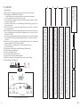
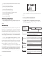
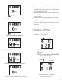
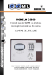
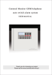
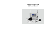
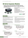
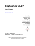
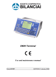
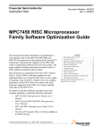
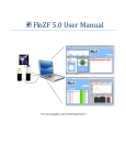
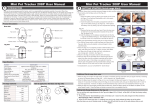
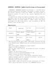
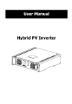
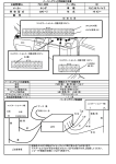
Centeral Monitor GSM/telephone
auto switch alarm system
USER MANUAL
8 Group zone/51 detectors/7 hard Wired detectors/one 12v alarm output
Thank you for choosing our panel
Please read the manual carefully before fix ing it.
Table of Contents
Quick reference
1 OVERVIEW............................................................................ 1
00: C.S. Comms. 11= send out information about arming, disarming and alarms; 10 = only
send out the alarm information; 00= not net work.
01: Exit delay time. The time is double-digit (XX). The actual time is the product of XX times
5. The initialization value is 04 = 20 seconds.
02: Entry delay time (delay alarm). The time is double-digit (XX). The actual time is the
product of XX times 5. The initialization value is 06 = 30 seconds.
03: Sounder run time. The time is double-digit (XX). The actual time is the product XX times
20. The initialization value is 06 = 120 seconds
04: Watchdog time. The unit time is hours.
05:Watchdog start and stop time window. Default setting is from 8:00 to 20:00.
06: Set time to Arm. Press * or #, select the time point( 6 time points in all) enter the time
desired. To cancel this set, press Delete key. Refer to figure 11.
07: Set time to Dis-Arm. Press * or #, select the time point( 6 time points in all) enter the
Time desired. To cancel this set, press Delete key. Refer to figure 12.
08: no use
09: PIN code set, this a 6 digit code for the remote access, Keypad Dis-Arm. Enter the
required PIN No using the numeric keypad on the panel. Cancel the PIN No using the
Delete key on the panel.
10: Set number of ringing in times before answer.
11. Arming with sounder ON/OFF
12: Two way communication
0: no sounder when arming
0: NO
1: sounder when arming
1: YES
13: Engineer Option. Listen to dial out DTMF.
0 : NO
1: YES
14: Mains Fail alarm. The panel will alarm when mains power fails 0 : NO
15: exit delay timer with sounder ON/OFF
0: ON
1:OFF
16: Phone line cut alarm:
M
SET
D
M
H
TYPE
2
1
LOG
0: NO
M
D
3
5
4
6
M
H
D
D
1
2
3
4
5
6
7
1:watchdog zone
1:exit delay
1:entry delay
0:not a watchdog zone
0:no exit delay
0:no entry delay
1:24 hours zone
1:sounder when alarming
1:armed zone
1:sensor in the zone
0:not 24 hours zone
0:silent when alarming
0:part armed zone
0:no sensor in the zone
7
1 1= local alarm only, when disarmed;
0=Normal detector
2 1= detector will be door bell, when disarmed;
0=not door bell
4 1= display detector low voltage on LCD;
27
2
3
4
2 DESCRIPTION.......................................................................3
2.1 The Keypad ...................................................................................... ...............3
2.2 The LCD Character details and description .........................................................4
3 INSTALLATION INFORMATION............................................9
3.1 The Basic Flow Chart ............................................................................ ...........6
3.2 Registering Key Fobs .................................................................................. .....7
3.3Registering Sensors ................................................................................... .......7
3.4 Installing Wired Detector ......................................................................... ........ 8
3.5 Checking Registration ............................................................................. ........8
3.6 Deleting Registered Key Fobs ..................................................................... ......9
3.7 Deleting Registered Sensors........................................................................ ..... 9
3.8 The Zone Setting and Allocation ............ ............................................ ...............9
3.9 The System Configuration Setting.................................................... ................11
3.10 The Phone Numbers Setting ............................... ......................... ..................13
3.11 The C.S Account Code Setting ............ ........................................ .................13
3.12 Deleting Zones ...................................................................... .......................14
3.13 Viewing The Recording Event Log............................................ ......................14
3.14 Setting Entry and Exit delay timer ............................................. ..................... 16
3.15 Sounder cutoff time..................................................................... ..................16
3.16 View detector's total in every zone............................................... ...................17
3.17 Speak and Listen in............................... ..................................... ...................17
3.18 Record & play the voice message................... .................................. .............. 17
4 USER INFORMATION..........................................................18
1: YES
3 1= key fob request assistance with sounder;
1
1:YES
1.1 Introduction ................................................................ ....................................1
1.2 Basic Principle of Operation ................................................ .............................1
1.3 Component Parts ..............................................................................................2
1.4 Optional Extra Detectors available.....................................................................2
0=key fob request assistance no sounder
0=Cancel detector low voltage display
4.1 Methods of Arming and Disarming.................................. .................................18
4.2 24 Hour Arming...............................................................................................19
4.3 Selectable Zone Arming............................................... ....................... ............19
4.4 Selectable Detector Alarming Local only or Local and C.S..................................19
4.5 Selectable Key Fob Requiring Assistance with/with out sounder.................. .......19
4.6 Omitting a Zone..................................................................................... .........19
4.7 Sounder or silent alarm setting................................................................ .........19
4.8 Access the Control Panel form a remote telephone(Mobile or Land line) .. ...........19
4.9 Listen in and speak through telephone.............................................................. 20
4.10 Alarm confirming ................................................................................ .........21
4.11 Detector battery low voltage display on the panel and introduction............... ....23
5 ZONE CONFIGURATION AND EXPLANATION................23
GSM Setting simple manual......................................................................
24
........................................
......
27
Quick refrence
To register Key fobs
To register sensors
Press PROG key
Press registered remote
key fob or enter your PIN
SENSOR appears on LCD
ready to register key fob or detectors
Activate the detector to be registered CODE appears on LCD, confirming the code has been received
Press 1--8 to select the zone you wish the detector to be allocated to. Unit will auto register the detector with next reg. No, eg, if already 3 detectors registered, the new detector will be allocated No 4.
Press PROG to save the code. SENSOR appears again to register more devices or press registered key
fob.
Activate the key fob to be register CODE appears on LCD, comfirming the code has been received .
Press 0 to select key fob zone. Unit will auto register key fob with next reg. No , eg. If already 2 key
fobs registered, the new key fob will be allocated No 3.Press PROG to save the code. SENSOR
appears again to register more devices or press registered key fob.
1 To register Key fobs
2 To register Detectors
3 To set Zone type
4 To set System configuration
5 To set C.S phone NO and site code
OR
OR
To set zone type
Press * key ,LCD will display ZONE TYPE, press 1---8 to select zone, select 1 or 0 for all 7 fields
per zone. Press PROG to save. Press * key, LCD will display ZONE TYPE to reset the other ZONE
TYPE or press registered key fob.
Remote
To set system config
PSTN
OR
Gas leak
Smoke
Premises
shock/vibration
Gas leak
Smoke
Wire detector
Wireless detector
PIR
Photoelectric Beam
V_PLEX PIR
PIR
Door contact Celling PIR
Private phone
Alarm centre
26
1
Press # key, LCD will display SYS CONFIG, press 00 to 15 to select the configuration of the system.
Press PROG to save. Press # key, LCD will display SYS CONFIG to re_configure the system or press
registered key fob.
1. Blue backup LCD display everything you want to konw about the panel.
2. Full compliance with ADEMCO Contact ID.
a. when alarming, you can hear which sensor in which zone is alarming
b.voice prompt you how to operate for every step
3.85 e vent logo about arming \ disarming \ alarming (with data stamp), viewable
directly on the panel LCD.
4. 12 seconds voice message, in case ofalarming,automatically playing after you
pick up your phone.
5. Any of the detector can be door bell when disarmed ; any detector can be local
siren when disarmed.
6. Monitor the old,the sick and the important place:when the old or the sick doesn’t
move, or the important warehouse hasn’t human presence for a period of time,
the panel will alarm.
7. Any zone type programmable(including:watchdog zone,exit/entry delay,24 hours
zone,sounder/silent when alarming,armed/part armed zone,sensor/no sensor in
the zone)
8. Panel can receive the detector low voltage signal and display zone number and
detector number on the LCD and sound a beep
9. 7 wired terminals,12v alarm output, 12v power output(continous),
wired siren terminal
10. 6 time points of timed Auto-Arming/disarming(24 hour mode)
11. Wireless detector installing test
12. Listen in and speak function
13. Away arming with siren sounder ON
14. any zone can be seperately armed/disarmed
15. Built-in high capacity rechargeable battery, auto charge/discharge
Press * key, then press # key, the LCD will display PHONE , press 1 and display current C.S. Pry 1
phone No, enter new Pry 1 phone No, press PROG to save the phone, press * key then # key, the LCD
will display PHONE, press 2 and display current C.S. Pry 2 phone No, enter new Pry 2 phone No,
press PROG to save, using this way, can set C.S. Account in Pry 7. or other private phone No, press
the registered key fob.
1.2 Basic Principle of Operation
OR
1.1 Introduction
To set C.S phone number
1.OVERVIEW
Figure1:Basic principle of operation
7. PROG the system configuration code :
Press PROG key--- enter the pin code or press disarm key of registered remote ---press # key–
press the 00 to 16 to select the configuration code---select 0 or 1 -
--press the PROG to store. T hen you can continue to PROG the panel---press # -
--press any Number from 0
0t o 1
6--- s elect 0 or 1 -
--press the PROG to store.
8. PROG the panel's time:
GSM panel time is decided by the GSM service. When you send sms to the gsm panel, and panel
got it correct, it would auto keep the correct time according to the gsm service.
9. How to program the SMS of every zone, every alarm:
Sending the SMS to the panel by the mobile phone, program the SMS: “12345601the first zone
fire active”(123456 is the factory default pin code, if you have already changed it, use your
new pin code),---then press the * key and hold it for about 2 seconds, t he U display
in the panel---then you send the SMS---the panel will sound 1
,3 o r 3
. 1 means correct,2 m eans pin code is wrong,3 m eans No is wrong. W hen panel sounds 1
,t hat means zone 1 sms is successfully set. T hen when detectors in zone one alarm, y ou will receive the sms.
Program the sms for other zones:
xxxxxx02 zone two active, p anic alarm
xxxxxx03 zone three active, the exit\entry zone alarm xxxxxx04 zone four alarming
xxxxxx05 zone five alarming
xxxxxx06 zone six alarming
xxxxxx07 zone seven activated, interior zone alarm
xxxxxx08 zone eight activated, w atchdog zone alarm
xxxxxx09 remote panic alarm xxxxxx10 tamper alarm
xxxxxx11 phone line cut alarm
xxxxxx12 main fails alarm
xxxxxx13 pin code input wrong for 3 times xxxxxx14 the panel armed
xxxxxx15 the panel disarmed
9. C heck the SMS setting status:
P ress the event/disarm key and hold it for 2 seconds, t he ”
GSM” on LCD would flash. This indicates the panel is sending all the program sms to programmed mobile numbers. If your mobile receives “
01 02 03,set sms ok” -
----this indicates: t he zone 1 2 3 SMS have been set.
If your mobile receives “
01 0
51 3,set sms ok” -
----this indicates: t he zone 01 05
13 SMS have been set.
If your mobile receives “set sms ok” -
-- t hat means you have not set any SMS
10 .Testing the panel:
P ress the arm key on the remote---the panel will display the armed zone in the LCD---trigger
the sensor in the armed zone---panel will alarm---if the SMS have set, t he “
GSM” will flash, t he panel will send the SMS to the phone number you set. (
when gsm is flashing, t he panel can not be disarmed)--- w hen the “GSM” is on, i ndicating the
SMS sent. (
if there is no SMS set, t he panel will dial the number without sending the
SMS) w hen the user picks up the phone, p ress * key to confirm the alarm, t hen the
panel will play the voice user recoded, and then told you which zone, which dector is
alarming by voice. Press 9 to listen the information again.
25
The above chart shows the basic principle of operation of the System. The security
system contains alarm panel, remote key fob, pir detectors, door/window magnetic contact
and high decibel integral siren Also available are some optional Devices such as wired/
wireless Smoke detectors, Gas detector, Flood detector, Temperature detector.The wireless
detector Communicates to the Control Panel by radio on 433 MHZ Frequency and each
detector has an approximate range of 50 Metres dependent on the Local Environments.
The wired detector are also workable.
1.3 Component Parts
The wired/Wireless Alarm Panel:
This 8 Zone Alarm panel is the central information processor of the system, receiving
and dealing with all the Alarm Signals from the various Detectors. It also contains the
central Station communicator and By-directional Audio Verification mechanism.
Everything you need to know about the security system is displayed on the panel keypad
LCD. The zones, 24 Hours, Armed, Part armed, Disarmed and the important Messages
regarding system status are displayed on the LCD screen. See section 2.1 and 2.2
Wireless Remote Key Fob:
The remote key fob is used to Arm,part arm,disarm the system or to request Assistance
from the C.S. This could mean the summoning of the Emergency Services such as Police,
Fire, Ambulance or just a member of the family. It is also used in the Programming and
device registration for system access.
1.4 Optional Extra Detectors available
Wired/Wireless Magnetic Door / Window contact: (option)
The Magnetic Door contact is used to detect the opening of doors or windows. When
activated it will transmit an alarm signal to the Control Panel to indicate a door or window
has been compromised. It consists of detector with an integrated wireless transmitter and
magnet.
Wired/Wireless PIR detector: (option)
The Passive Infrared detector responds to mobile body heat emissions. If anyone enters
the area of an Armed Zone, once the infrared detector in that Armed Zone detects their
presence it will transmit an alarm signal to the Control Panel.
2
Zone 8 selected
Wired/Wireless Smoke detector: (option)
M
The Smoke detector is used to detect potentially dangerous smoke emissions in the home.
Once the detector detects the presence of smoke as a danger and possible Fire Risk it will
transmit an alarm signal to the control panel and also activate its own integral local sounder.
Wired/Wireless Combustible Gas detector: (option)
The combustible gas detector will detect potentially dangerous gas emissions within its
location. It should be fitted in any area where there is a possibility or risk of Gas Leaks or
emissions.
Once The Combustible Gas detector detects unacceptable levels of combustible Gas it
will transmit an alarm signal to the Control Panel and also activate its own integral local
sounder.
SET
D
H
M
D
TYPE
The above shows No 8 zone configured, a watchdog zone (24 hour armed), there
are Sensors in this Zone.
BasicFlow chart for registering devices,sSet zone type,set system configuration
and program C.S. phone numbes and site code in disarmed mode.
GSM Setting simple manual:
Wiredless shock/vibration detector: (option)
Glass Break detector: (option)
The glass break detector should be placed at home where close to glass. When the glass
is broken, the detector could detect the particular frequency and then transmitting an alarm
signal to the control panel.
2 DESCRIPTION
2. 1 The Keypad
ARMED ON
PART ARMED ON
ALARM ON
ALARM FLASH
POWER ON
voice OFF
POWER
Event/Disarm
Prog
Del/Sensor
Arm
= ARMED
= PART ARMED
= NEW ALARM LOG
= ALARM OR COMMUNICATION
=AC POWER
=BATTERY USING
Event LOG/Disarm; Press and hold it for
2 seconds, check the SMS information
Program
Delete/Sensor check
Manual ARM or PART ARM
*
voice
9
RF out
turn on/off voice; press and hold it
for 2 seconds enter SMS setting
RF transmit for wireless siren
0 recording the owner voice/
OGM
#
playback the voice
Press (walk test) or Press & hold
up (alarm with/without sounder)
Figure 2:keypad description
3
1. Insert the GSM SIM card into the panel, C onnect the antenna on the top and screw
the screw cap. Not too tight. Plug in the adatpor, a nd turn on the back switch on PCB. 2. After 30 seconds, the panel connect to gsm network, and LCD show the time
3. connect the phone line (optional), if you connect the phone line, the panel would send SMS
by gsm sim card first (if the sms is set in the alarming zone) then dial from the telephone line. If there is no telephone line,the the panel would send sms by gsm sim card first (if the sms is set
in this alarming zone) then dial from the gsm sim card also.
4. Register the remote: press the PROG key---input the factory default pin code 123456—
press the remote key---“code” display in the LCD, indicating the panel receive a wireless
signal---press the numeric key 0, 0 stands for remote ---press the PROG key to store the data.
Then you can register other remote same as above steps.
5. Register the sensor: press the PROG key---enter the pin code or press the Disarm key on a
current registered remote---trigger the sensor---“code”displays in the LCD, i ndicating
the panel receives a wireless signal---press the numeric 1 to 8, s elect the zone number—
press the PROG key to store the data. Then you can register other sensors same as above steps.
In any step, you can press the disarm key of the remote to escape.
Note: when you select the zone:
Zone 1 is 24hours zone fire alarm (detectors in the zone also alarm in disarmed mode)
Zone 2 is 24hours zone panic alarm( detectors in the zone also alarm in disarmed mode)
Zone 3 is entry/exit zone (extry/exit delay timer)
Zone 4.5 6 are normal zones
Zone 7 is interior zone : det ectors in this zone do not alarm in par t arm
Zone 8 is watchdo g zone : det ector alarms when no movem ent for a progr ammed per iod
6. PROG the phone number:
Press the PROG key---enter the pin code or press the registered remote ---press * then # key—
press the1 to 6 for selecting the phone number position---input the phone number---press the
PROG to store. Then you can continue to PROG the panel—press * # ---press the 1 to 6 to
choose phone position--- input the phone number---press the PROG to store.
24
5 ZONE CONFIGURATION AND EXPLANATION
Note:
GND: the negative electrode of the
power supply , siren , wired
detector and alarm output
Zone 7 selected
M
SET
D
M
H
D
L1.L2.L3.L4.L5.L6.L7 (wired detector):
The signal wire of the wired detector
TYPE
+12V Siren V OUT L7
input
L6
L5
L4
L3
L2
L1 Lamp GND
Lamp: output control signal when
alarm
12V
1
1
2
3
4
5
6
7
2
3
4
5
6
1:watchdog zone
1:exit delay
1:entry delay
1:24 hours zone
1:sounder when alarming
1:armed zone
1:sensor in the zone
7
Power
0:not a watchdog zone
0:no exit delay
0:no entry delay
0:not 24 hours zone
0:silent when alarming
0:part armed zone
0:no sensor in the zone
Zone 1 selected
M
SET
D
M
H
Phone
TYPE
OFF
LOG
DIS PART
ARMED
WatchDog
M
SETRMOT TYPECONFIG ALM
M
D
M
H
D
H
M
D
PIN TESTTIMED GSM PHONE
D
TYPE
The above shows Zone 2 is configured to be a panic zone, Active Sounder when Arming
and there are Sensors in this zone.
Zone 3 selected
ON=Sounder as alarm
OFF=Silent as alarm
Panel armed
ARMED
Panel disarmed
DIS ARMED
Panel part armed
PART ARMED
Watchdog
M
D
H
M
D
TYPE
The above shows that the No 3 zone configured to be a Entry/Exit, Active Sounder when
Arming and there are sensors in this zone.
23
ON
2. 2 The LCD Character details and description
2.2.1 The panel LCD screen whole information shows as follows:
D
Zone 2 selected
SET
Phone line
Figure 3: The back view of the panel
Everything you need to know about your Security System is displayed on the Panel
keypad. The zones armed or disarmed and the important messages regarding system status
appear on the LCD screen.
The above shows Zone 1 is Configured to be a 24 hour zone, Active Sounder when
Arming and there are Sensors in this zone.
SET
1
+
2v:power input
siren:out
put 2V
1 or
fh
t
e w
i
r
ed si
r
enor
t
o
her cc
a
essor
i
es hw
en l
a
a
r
m
vout: 2
1
voutput power for wired
accessories
LOG
M
D
H
M
D
Avaible
Event log
Month
Day
Hour
Minute
Weekday
SET
RMOT
TYPE
CONFIG
ALM
PIN
TEST
TIMED
GSM
PHONE
Set program
Remot
Zone type
System config
Alarm
Wireless sensor battery low voltage
Pin code
Walk test
Timed auto arm or disarm
flahsing: group sending SMS
on gsm is dialing
C.S. Phone or user owner phone
Figure 4: All the info. the LCD displays
4
If after 15 seconds the user does not press the * key to confirm the alarm, the panel will
If no action has been performed on the keypad and the panel is in the DISARMED mode,
the panel LCD screen will show as following:
auto dial next phone number.
After the entry of the listening in status, the next operating steps are same as the remote
DIS
ARMED
control In section 4.9 previous.
M
LOG
D
M
H
D
4.11 Detector Battery Low Voltage Display On the Panel And Introduction
TIMED
}
Low GSM Si
gnal
Figure5 : LCD display when disarmed
When detector has been in the low voltage state, it will not run correctly. The Panel can
receive the detector low voltage signal and display on the LCD and sound a beep to indicate
user to replace detector's battery in time.
Low voltage display and introductions:
: it means that the panel has been set to sounder alarm
: It means there are 85 items of information (including alarm information,
85
Armed / disarmed information and others).
10 M 8 D : It means the date: November 8th.
18 H 52 M : It means the time: 18:52
: It Means weekday Tuesday.
D 2
A: When the panel is in the DISARMED mode, if the detector such as PIR detects itself
being low voltage, the panel will sound a beep every seconds and display the signal
On the LCD continually.
LOG
Timed
: It means timed auto arming/disarming has been programmed
02
: It means there are 2 items of alarms which have not been viewed. After
1
Viewing the information, the display 02 will disappear.
: It means that the No. 1 zone armed within 8 zones from No.1 to No.1 8 Zone.
M
D
H
M
D
Figure 23: Detector No 2 in zone 3 is low voltage
2.2.2 When the panel is set in the away armed mode,the LCD screen will show the following :
B: When the panel is in the Armed/PART Armed mode, if the detector such as PIR detects
itself being low voltage, the panel will sound a beep every seconds and display the signal
armed zone and detectors No on the LCD alternately.
ARMED
LOG
M
D
H
M
D
}
Mi
ddl
eGSM Si
gnal
C: Even if the panel LCD displays the detector low Voltage, the operation also can be
done normally on the panel and stop provisionally low voltage display.
How to cancel the low voltage display:
Figure 6: LCD display when part armed
A: Press 'Delete' key and - - - appears on the LCD. Press registered Key Fob or enter your
The meaning of the characters as follows:
83:Means there are 83 items of information (including alarm information, Armed/Disarmed
information and others).
PIN, LCD will display 'DEL Sensor' use keypad to select zone(s) 1 to 8. Use Keypad to select
Detector(s) 1 to 9. Program the 4th field with 0. Press Key Fob Exit. (Refer to figure 25)
B: Press the key Fob, the beep and display would stop for one hour.
1234 78 : Means that Zone No. 1, 2, 3, 4,7and 8 zones are armed.
Zones 5 & 6 are Un-Armed as there are no sensors in the two zones
2.2.3 When there is an alarm, the panel LCD will show as following:
5
N.B.: When the battery has been replaced, the user must program the 4the field with 0
manually. And then the panel will display normally.
22
After entering correct PIN code the panel will follow the instructions given using the
DTMF tones from the keypad of the remote phone.
LOG
Press 1 to tell the panel to switch to listen in mode
M
D
H
M
D
ALM
Press 2 to tell the panel to switch to speak mode
}
Hi
ghGSM Si
gnal
Press 3 to tell the panel to switch its sounder ON
Press 4 to tell the panel to switch listening in OFF
Figure7 : LCD display when alarmed
Press 5 to tell the panel to terminate the call, disengage the phone line
Press 6 to tell the panel to switch its sounder OFF
Press 7 to tell the panel to ARM
The figure shows that Zone 3 detector No2 has generated the Alarm signal at 6:10 on
18 th, Oct.
Press 8 to tell the panel to DIS ARM
4.9 Listen in and speak through telephone
When the phone connected to the panel is call ed ,and the phone rings , press a single
key on the telephone directly , then the user could Listen in the premise and speak to the
occupants.
3 INSTALLATION INFORMATION
3.1 The Basic Flow Chart for Registering Devices, Set Zone Type,
Set System Configuration and Program C.S. phone numbers and
Site Code in Disarmed mode.
4.10 Alarm confirming
When the panel reports an alarm event to the C.S.it does so by using Ademco contact
ID protocol. After the data is transferred to the C.S. The operator then has access to the
1 To register Key fobs
2 To register Detectors
3 To set Zone type
4 To set System configuration
5 To set C.S phone NO and account
Press PROG key
Press registered remote
key fob or enter your PIN
SENSOR appears on LCD
ready to register key fob or detectors
customer details, address, name, phone numbers, key holders etc.He also has audio access
to the premises.He can listen-in or speak to the occupants,this will allow the C.S. operator
to request a pre-arranged password to confirm the identity of the person he is speaking to
To register Key fobs
or make a challenge to an unindented occupant.The C.S. operator will take the appropriate
action determined by the circumstances at the time.
OR
The C.S. Pry 1 and Pry 2 phone numbers are located in fields 1 and 2 and the account
To register Sensors
code is located in field 7 in the PHONE program and configuration. In addition to above
procedure the panel has the ability to report alarm incidents to up to 4 private telephone
To set zone type
Press * key ,LCD will display ZONE TYPE, press 1---8 to select zone, select 1 or 0 for all 7 fields
per zone. Press PROG to save. Press * key, LCD will display ZONE TYPE to reset the other ZONE
TYPE or press registered key fob to exit
To set system config
Press # key, LCD will display SYS CONFIG, press 00 to 17 to select the configuration of the system.
Press PROG to save. Press # key, LCD will display SYS CONFIG to re_configure the system or press
registered key fob to exit
program and configuration. These numbers are referred to as USER numbers.
OR
panel Can be programmed to call the USER numbers in sequence, i.e No3 field First, then
4 etc.
When the panel dials the user phone number and the user answers the telephone,
there will be a beep sound from the panel showing that the phone is being answered. The
user then presses the * key on USER hand set to confirm the alarm, on doing so the panel
will allow the USER to listen-in the premises.
21
Activate the detector to be registered CODE appears on LCD, confirming the code has been received
Press 1--8 to select the zone you wish the detector to be allocated to. Unit will auto register the detector with next reg. No, eg, if already 3 detectors registered, the new detector will be allocated No 4.
Press PROG to save the code. SENSOR appears again to register more devices or press registered key
fob to exit
OR
numbers. These dedicated numbers must be programmed into fields 3 to 6 of the PHONE
After reporting an alarm event to the C.S., once the C.S. has terminated the call the
Activate the key fob to be register CODE appears on LCD, comfirming the code has been received .
Press 0 to select key fob zone. Unit will auto register key fob with next reg. No , eg. If already 2 key
fobs registered, the new key fob will be allocated No 3.Press PROG to save the code. SENSOR
appears again to register more devices or press registered key fob to exit
OR
To set C.S phone number
Press * key, then press # key, the LCD will display PHONE , press 1 and display current C.S. Pry 1
phone No, enter new Pry 1 phone No, press PROG to save the phone, press * key then # key, the LCD
will display PHONE, press 2 and display current C.S. Pry 2 phone No, enter new Pry 2 phone No,
press PROG to save, using this way, can set C.S. Account in Pry 7. or other private phone No, press
the registered key fob to exit
6
4.5 Selectable key fob require assistance with/without sounder
3.2 Registering Key Fobs
How to set the function: Press 'Delete’ key and - - - appears on the LCD. Press the disarm
Logging in Key Fob: Press the PROG key on the Keypad, a series of - - - will appear on
the LCD. Enter the PIN code or Press the Disarm key on a current registered Key Fob and the
word 'Sensor' will appear on the LCD (when logging in the first keyfob, pin code is needed,
the factory default pin code is: 123456 ); Using the key fob you wish to register, press the
disarm key on the Key Fob, the panel will receive the Key Fob code and the LCD will show
the word 'CODE' (refer to below figure 8) . Press 0 key on the Keypad to identify you are
registering a Key Fob. The LCD will now display the Key Fob number that it has allocated to
that Key Fob. Press the PROG Key to complete and save the information. The Key Fob is
now registered and recognized by the control panel.
key on the registered Key Fob or entering the preprogrammed PIN code, LCD will display
'DEL Sensor' Use Key pad to select Zone(s) 0, then select key fob number 1 to 9.Program the
character of the Key Fob with 0 or 1 to suit. Press Key Fob or ESC to save and exit. refer to
figure 25.
4.6 Omitting a Zone
It may be a requirement to temporarily omit a selected Zone or a number of Zones when
the system is armed. When a zone is selected to be omitted it will only be omitted for current
operation. When next time your System is armed, the omitted ZONE or ZONES will be
If no further actions take place the panel will automatically return to normal state after
approximately 30 seconds. Otherwise at the end, press the Dis-Arm key on a registered Key
Fob to return the panel to normal state.
Note: whenever a PIN code is necessary ,if you enter a wrong PIN code for 3 times ,the Panel
will alarm automatically. refer to figure 24
re-enstated into the system.
Note: The function is suitable for the armed zone or zones. But 24 hour zone can never
be omitted.
How to Omit a zone or zones: Press Arm button on the panel, then using the numeric
LOG
M
D
H
M
D
SET
keypad on the panel press the number of the zone want to be omitted, then press the Disarm
key, enter the PIN code to complete the operation.
4.7 Sounder or Silent alarm setting:
Figure 8
How to set the function: Press the # key for 2 seconds when the panel is in disarmed mode,
the symbol of speaker displays or disappears; When it displays, the panel would alarm with
3.3 Registering Sensors
sounder ON, while when it disappears, the panel will alarm silently.
Note: Whether the key fob alarms with/without sounder subjects to its own configuration.
Logging in Sensors: Press the PROG Key on the Keypad, a series of - - - will appear on
the LCD. Enter the PIN code or Press the Disarm key on a current registered Key Fob and the
word 'Sensor' will appear on the LCD. Trigger the detector you wish to register, the Panel
will receive the detectors code and the word 'CODE' will appear on the LCD ( refer to figure
8). Pressing a numeric key 1 to 8 on the Keypad will select the Zone you wish to allocate the
detector. e.g. Pressing No 3 on the Keypad will allocate the detector to Zone 3. The control
panel will then automatically allocate the detector with the next available detector number in
that Zone. So, if there are no detectors allocated in Zone 3 the control panel will allocate it as
detector No 1 and the next detector to be registered in Zone 3 will be allocated detector No 2
etc. To complete and save the information press PROG key.
When the panel is set with silent alarm, the key fob will still be sounder alarm if it is set with
sounder alarm.
4.9 Access the Control Panel from a remote telephone (mobile or
land line)
The Remote Control enables the use of the land line phone or mobile phone to remotely
control panel. Call the phone number of the line connected to the alarm panel, the panel will
answer the call after 1 to 8 rings (programmable). When the panel answers the call enter the
pre-programmed 6 digit PIN code on the phone keypad to gain access to the Panel.
If the correct 6 digit PIN code is entered a long tone will be emitted from the panel. If the
If no further actions take place the panel will automatically return to normal state after
approximately 30 seconds. Otherwise at the end, press the Dis-Arm key on a registered Key
Fob to return the panel to normal state.
7
PIN code is incorrect, three short tones will be emitted from the panel.You must try again and
enter the correct PIN code.
20
4.2 24 Hours Arming
3.4 Installing wired detector and its zone setting:
24 hours arming is used for the detectors ( i.e. smoke detector and gas detector etc ),
These zones are armed 24 hours whether the system is armed or disarmed. They can at no
time be omitted or disarmed.
connection in all, and the terminals for connection are 1\2\3\4 \5\6\7, GND is the common
Various wired detector could be connected to the panel via the N.C terminal. Seven wired
GND terminal.
4.3 Selectable Zone Arming
Zone setting: After connecting well the wired detector to the panel, press the PROG key
This facility allows only a particular selected zone or only a particular selection of
zones to be armed. This is of great use when requiring temporary protection in a selected
area while the premises is occupied.
How to action Selectable Zone Arming: Using the numeric Keypad on the panel, press
the number of the Zone you wish to arm (refer to 1 to 8 zone), then press the ARM key to
arm. When both the Armed and Disarmed lights illuminate arming is completed. The
armed zones will be displayed on the LCD alongside with the 24 hour zones.
4.4 Selectable Detector Alarming Local only or Local and C.S.
on the keypad, a series of ----- appear on the LCD. Enter the PIN code or press the Disarm key
on a registered key fob and the word 'Sensor' will appear on the LCD. Trigger the detector you
wish to register, the panel will receive the detectors code and the word 'CODE' will appear on
the LCD.Pressing a numeric key 1 to 8 on the keypad will select the zone you wish to allocate
the detector. e.g. Pressing No 3 on the keypad will allocate the detector to Zone 3. The control
panel will then automatically allocate the detector with the next available detector number in
that Zone. So, if there are no detectors allocated in Zone 3 the control panel will allocate it as
detector No 1 and the next detector to be registered in Zone 3 will be allocated detector No 2
This facility allows particular detectors in each Zone to be local alarm only or local
alarm and transmit alarm information to the C.S,each detector can be configured differently
e.g. local Alarm only or local Alarm and C.S. function, door bell function or in the case of
Key Fob, Request Assistance with / without sounder.
etc. To complete and save the information press PROG key.
( Also you could first fix two wires to terminal 1.2.3.4.5.6 or 7 and GND, then connect
them together. Disconnect them when triggered. It is ok then to replace with a wired detector
How to set the function: press 'Deleter’ key and - - appears on the LCD. Press registered
Key Fob or entering the preprogrammed PIN code, LCD will display 'DEL Sensor' Use Key
pad to select Zone(s) 1 to 8. Use Key pad to select detector(s) 1 to 9. Program each of the 3
fields of the detector with 0 or 1 to suit. Press Key Fob or ESC to save and exit.
after registration.)
3.5 Checking Registration
Checking key fob and sensor registration: press the # key on the keypad, the LCD displays
word TEST, Activate a detector, a bleep noise will be heard confirming the control panel has
LOG
M
D
M
H
D
received the signal from the detector and the LCD will display the Detector registration No
and its Zone allocation e.g. Activate Detector No 2 in Zone 3 the LCD will
1
2
3
4
LOG
1
2
3
4
1= local alarm only, when disarmed;
1= detector will be door bell, when disarmed;
1= key fob request assistance with sounder;
1= display detector low voltage on LCD;
M
D
H
M
D
TEST
0=Normal detector
0=not door bell
0=key fob request assistance no sounder
0=Cancel detector low voltage display
Note: field 1,2,4 are for detector; field 3 is for Key fob
Figure 22: Detector features setting
19
Figure 9
8
Press the key fob Dis-Arm will return the control panel back to normal status. Otherwise
the Walk Test will Auto extinguish approximately 30 seconds after last test signal was
received.
LOG
M
D
H
M
D
3.6 Deleting Registered Key Fobs
Deleting Registered Key Fob: Press the DELETE key on the Keypad, a series of - - - will
4 USER INFORMATION:
appear on the LCD. Press the Disarm key on a current registered Key Fob or entering the
preprogrammed PIN code, and the word 'DEL Sensor' will appear on the LCD.Press '0' on the
numeric Key pad to select the Key Fob Zone and the LCD will display Zone 0, press the
4.1 Methods of Arming and Disarming
registered No of the Key Fob you wish to delete. e.g. key fob No 2, the LCD will now display
Arming: Arming is used to arm the whole Alarm system. All detectors in the zones within
the protected area must be closed(not in alarm)in order for you to arm the system successfully.
Zone 0 2. Press DELETE key to delete No 2 Key Fob.
If no further actions take place the panel will automatically return to normal
state after approximately 30 seconds. Otherwise at the end, press the Dis-Arm key
on a registered Key Fob to return the panel to normal state.
Part Arming: Part Arming is used to partially Arm your System by arming the selected
zones in the protected area,which permits persons to remain in the premises while the system
is Part Armed.
3.7 Deleting Registered Sensors
Disarming:Disarms the system and deactivates any alarms in progress and disarms all the
zones other than the 24 hour Zones.
Deleting Registered Sensors: Press the DEL key on the Keypad, a series of - - - will
appear on the LCD. Press the Disarm Key on a current registered Key Fob or entering the
preprogrammed PIN code, and the word 'DEL Sensor' will appear on the LCD. Press 1 to 8
on the numeric Keypad to select the Zone the detector to be deleted is allocated to. e.g. Zone
3 and the LCD will display Zone 3, press the registered No of the detector you wish to delete.
e.g. detector No 2, the LCD will now read Zone 3 2. Press Delete key to delete No 2 detector
in Zone 3.
4.1.1. Arming and Disarming through the Keypad on the panel
How To Arm: Pressing the ARM key on the keypad to arm the system.
How To Part Arm: Pressing the ARM Key on the Keypad for 2 seconds to Part Arm the
system.
How To Disarm: Press the DISARM key on the keypad then using the Keypad again enter
the pre-programmed 6 digit PIN code to complete the disarming operating.
If no further actions take place the panel will automatically return to normal state after
approximately 30 seconds. Otherwise at the end, press Dis-Arm key on a registered Key Fob
4.1.2. Arming and Disarming through the Key Fob Remote Device
to return the panel to normal state.
How To Arm: Press the Arm key on the Key Fob to Arm the system.
3.8 The Zone Setting and Allocation
The alarm system has 8 zones which can be configured depending on your requirements.
How To Part Arm: Pressing the Part Arm key on the key Fob to Part Arm the system.
How To Disarm: Press the DISARM key on the key Fob to Dis-Arm the system.
The Factory Default Zone configuration settings are as follows:
No 1 Zone Fire;
No 2 Zone Panic ;
No 3 zone: Entry/Exit ;
No 4 . 5 . 6 Zone Exterior Intruder;
No 7 Zone Interior Intruder ; No 8 zone Watchdog
9
Note: The armed LED flashes to show that the delay timer is being activated for those
zones with delayed time. The zones without a delayed timer is armed. When the armed LED
light, it shows Arming has completed. All the exterior Zones Arm immediately when part
armed, the delay timer will not work under such circumstances.
18
Setting the sounder cut off time: Press the PROG key on the Keypad, a series of - - - will
appear on the LCD. Press the Disarm key on any current registered Key Fob or entering the
How to allocate and set zones: Press the PROG key on the Keypad, a series of - - - will
preprogrammed PIN code, then the word 'Sensor' will appear on the LCD. Pressing the # key
appear on the LCD. Press the Disarm key on any current registered Key Fob or entering the
on the Keypad, the LCD will show the words 'SYS config'. Press 0 then 3 on the numeric
preprogrammed PIN code, and the word 'Sensor' will appear on the LCD. Pressing the * key
Keypad. 03 will appear in the top left hand corner of the LCD (refer to section 3.9 for the
on the Keypad, the LCD will show the words 'Zone type', pressing No1 to 8 numeric key to
configuration codes). Enter the required cut off time using the configuration code. The
select corresponding zone, then pressing the 0 or 1 numeric Keypad to configure all the
selected code will be displayed in the bottom right hand corner of the LCD. Press PROG to
fields in this zone. At the end, press the PROG key to complete and save operation.
store this number.
If no further actions take place the panel will automatically return to normal state after
approximately 30 seconds. Otherwise at the end, press the Dis-Arm key on a registered Key
Fob to return the panel to normal state.
3.16 View detector's total in every zone
By way of example, below is configured as follows:
Zone 7 selected is a Watchdog Zone programmed without entry or exit time, it's a 24
hour .
Zone with silent when alarming, its an internal detector and there are sensors allocated
to it.
Zone 7 selected
How To view the detector's total In a Zone: Press the Sensor key on the keypad, a series
of - - - will appear on the LCD. Press the Disarm key on any current registered Key Fob or
enter the preprogrammed PIN code, and the word 'DEL Sensor' will appear on the LCD.
M
Using the *and # keys scroll through the Zones and their registered detectors. e.g. If the
SET
D
M
H
D
TYPE
LCD displays: Zone 0 2 this means 2 key fobs are registered. If the LCD displays Zone 5 3
means 3 detectors are registered in the Zone 5 etc.
3.17 Speak and listen in
The function of speak and listen in: When the Panel alarms, the C.S operator or user
could access the speak and listen in function of the panel by pressing the corresponding
1
2
3
4
5
6
7
keys on the telephone keypad, then the user or operator could know what is going on within
the premise.(the MIC & SPEAK inside the panel)
3.18 record & playback the private voice
Function: When the panel alarms, it will auto dial the user telephone numbers After the
user press the * to confirm, he can listen to the recorded alarming message, which informs
the user what happens. The user can press 9 to replay the message.
How to record/play the message: In the disarmed status, press the OGM and hold it
1
2
3
4
5
6
7
1:watchdog zone
1:exit delay
1:entry delay
0:not a watchdog zone
0:no exit delay
0:no entry delay
1:24 hours zone
1:sounder when alarming
0:not 24 hours zone
0:silent when alarming
0:part armed zone
1:armed zone
1:sensor in the zone
0:no sensor in the zone (disabled)
for 2 seconds. The panel LCD will display COPY.At this time, you can record the alarming
message now. The recording time is 12 seconds. Press OGM, you can hear the recorded
Figure 10: zone type configuration
message.
17
10
N.B. For a more detailed example refer to section 5. Zone Configuration and Explanation.
If no further actions take place the panel will automatically return to normal state after
approximately 30 seconds. Otherwise at the end, press the Dis-Arm key on a registered Key
Fob to return the panel to normal state.
3.9 The System Configuration Setting
How To set system configuration: Press the PROG key on the keypad, a series of - - - will
appear on the LCD. Press the Disarm key on any current registered Key Fob or entering the
preprogrammed PIN code, and the word 'Sensor' will appear on the LCD. Pressing the # key
on the Keypad, the LCD will show the words 'SYS Config', pressing 0 to 9 on the numeric
Keypad to select each Configuration Field Code from 00 to 17 in succession and configure
each field as required. At the end, press the PROG key to save, store the information and exit.
If no further actions take place the panel will automatically return to normal state after
3.14 Setting Entry and Exit delay timer
Exit Delay Timer: In order to provide a user with enough time to leave the premises, an
EXIT DELAY TIMER will commence timing when a user arms the system, The timer will
last anywhere from 1 to 255 seconds depending on time selected when configuring the
system.
How to set the Exit delay time: Press the PROG key on the Keypad, a series of - - - will
appear on the LCD. Press the Disarm key on any current registered Key Fob or entering the
preprogrammed PIN code, and the word 'Sensor' will appear on the LCD. Pressing the # key
on the Keypad, the LCD will show the words 'SYS config'. Press 0 then 1 on the numeric
Keypad. 01 will appear in the top left hand corner of the LCD (refer to section 3. 9 for the
configuration codes). Enter the Required Exit Time using the configuration code. The
selected code will be displayed in the bottom right hand corner of the LCD. Press PROG to
store this number.
If no further actions take place the panel will automatically return to normal state after
approximately 30 seconds. Otherwise at the end, press the Dis-Arm key on a registered Key
approximately 30 seconds. Otherwise at the end, press the ESC on the keypad or the Dis-Arm
Fob to return the panel to normal state.
key on a registered Key Fob to return the panel to normal state.Entry Delay timer:Designated
Configuration Codes
where from 1 to 255 seconds depending on time selected when configuring the system.
entry points ( i.e. front door and may be back door ) are subject to an Entry Delay Time any
00: C.S. Comms. 11= send out information about arming, disarming and alarms; 10 = only
send out the alarm information; 00= not net work Default:00
01: Exit delay time. The time is double-digit (XX). The actual time is the product of XX
times 5. The initialization value is 04 = 20 seconds.
02: Entry delay time (delay alarm). The time is double-digit (XX). The actual time is the
product of XX times 5. The initialization value is 06 = 30 seconds.
03: Sounder run time. The time is double-digit (XX). The actual time is the product XX times
20. The initialization value is 06 = 120 seconds.
04: Watchdog time. The unit time is hours. The factory default value is 12hours.
05: Watchdog start and stop time window. Default setting is from 8:00 to 20:00.
06: Set time to Arm. Press * or #, selec the time point( 6 time points in all) enter the time
desired. To cancel this set, press Delete key. Refer to figure 11.
07: Set time to Dis-Arm. Press * or #, select the time point( 6 time points in all) enter the
Time desired. To cancel this set, press Delete key. Refer to figure 12.
This delay provides a user with enough time to enter the armed premises and disarm the
system before an alarm is triggered.
How To Set Entry Delay Timer: Press the PROG key on the keypad, a series of - - - will
appear on the LCD. Press the Disarm key on any current registered Key Fob or entering the
preprogrammed PIN code, and the word 'Sensor' will appear on the LCD. Pressing the # key
on the Keypad, the LCD will show the words 'SYS config'. Press 0 then 2 on the numeric
Keypad. 02 will appear in the top left hand corner of the LCD ( refer to section 3. 9 for the
configuration codes). Enter the required entry time using the configuration code,the selected
code will be displayed in the bottom right hand corner of the LCD. Press PROG to store this
number.
If no further actions take place the panel will automatically return to normal state after
approximately 30 seconds. Otherwise at the end, press Dis-Arm key on a registered Key Fob
to return the panel to normal state.
3.15 Sounder cut off time
The sounder cut off time is the time permitted for the sounder to sound when an alarm
activation takes place. This can be from 1 to 1980 seconds, or do not stop until the C.s or user
confirm it, depending on time selected when configuring the system.
11
16
08: Set time and date (the time is set by gsm SMS, can not be set manually)
LOG
M
D
H
M
D
ALM
ALM :tamper alarm
Figure16: The LCD display when there is a tampered alarm
LOG
M
D
H
M
D
ALM
ALM :main power fail alarm
09: PIN code set, this a 6 Digit Code for the Remote Access, Keypad Dis-Arm. Enter the
required PIN No using the numeric Keypad on the panel. Cancel the PIN using the
Delete key on the panel. Default PIN: 123456
10: Set number of ringing in times before answer. Cancel this set using Delete key on the
panel. When the PIN code or the number of ringing is not set, the panel couldn't have
Remote access; Default : 9
11. Arming with sounder ON/OFF 0: no sounder when arming 1: sounder when arming
12: Two way communication ---Speak: 0: No 1: YES. Default: 0
When SPEAK is required, within 2.5 seconds after transmitting data to the C.S, the
Panel. Will receive the SPEAK request from C.S. If it is not required, the panel hangs
up automatically
13: Engineer Option. Listen to dial out DTMF. 0 = NO : 1 = YES. This option will
Automatically extinguish when the panel is closed or on the hour. Default:NO
14: Mains Fail alarm. 0 = NO ; 1 =YES Default: NO
15: Exit delay timer with beep on/off 0:off 1: on Default: on
16: Phone line cut alarm: The panel will automatically check the line and alarm when It
Detects it is not ok. 0: NO 1: YES. Default: NO
Figure17: The LCD display when the power fails
System config
LOG
M
D
H
M
Auto armed time
D
ARMED
ALM
M
H
SET
CONFIG
TIMED
The second auto armed Auto armed
Figure18: The LCD display when the wireless detector is alarming
The second auto armed:press * or # to select the 1– 6
ARMED:default
LOG
M
D
H
M
D
PART ARMED:press the arm key to select ARMED or PART ARMED
Figure11: The second auto armed time is at 13:30
ALM
System config
Auto disarmed time
Figure19: The LCD display when the wired detector is alarming
M
H
SET
LOG
M
D
ALM
PIN
H
M
CONFIG
TIMED
D
The first auto disarmed
Auto disarmed
The first auto disarmed:press * or # to select the 1--6
Figure 20:The LCD display when the PIN code is entered wrong for 3 times.
15
Figure12: The first auto disarmed time is at 17:35.
12
3.10 The Phone Numbers Setting
How To Set Phone Number: Press the PROG key on the Keypad, a series of - - - will
appear on the LCD. Press the Disarm key on any current registered Key Fob or entering the
Keypad, the LCD will display 'Zone 3'. Using the numeric Keypad select the number of the
detector requiring to be deleted. e.g. Detector No 4 in Zone 3. The LCD will now display
‘Zone 3 4'. Press DELETE and the detector will be deleted from memory.
B: Enter the location of zone type setting, set the No 7 field to 0, refer to 3.8 figure 10.
preprogrammed PIN code, and the word 'Sensor' will appear on the LCD. Pressing the * key
on the Keypad, the LCD will show the words 'Zone type'. Pressing the # key on the Keypad,
the LCD will show the words 'SYS phone'. Press No 1 on the numeric Keypad. Enter the full
phone number of the Central Station Comms.and press PROG to store this number. Pressing
* then # scroll back down to 'SYS phone' Press No2 on the numeric Keypad. Enter the full
phone number of the Central Station secondary number for comms using the numeric keypad
on the panel, then Press PROG to store this number. The No 1 and 2 are for C.S. Phone
3.13 Viewing The Recording Event Log
Events refer to occurrences taking place within your s ystem, such as, which key Fob
Armed or Dis-Armed the system and when. If an alarm occurred which detector in which
Zone activated the alarm and when.
How To View the event record: press the * key on the keypad, the panel LCD will show
the latest event, using the * and # keys to look over previous events, times and information.
Note: the top line always shows the latest event information.
numbers, No 3 to 6 are for personal numbers. If not networking, No 1 and 2 can also be set
with personal numbers.
If no further actions take place the panel will automatically return to normal state after
M
LOG
RMOT
D
H
M
D
ALM
approximately 30 seconds. Otherwise at the end, press the Dis-Arm key on a registered Key
Fob to return the panel to normal state.
3.11 The C.S. Account Code Setting
How To Set C. S. Code: Press the PROG key on the numeric Keypad, a series of - - - will
appear on the LCD.
Press disarming key on any current registered key fob or entering the preprogrammed
PIN code, and the word 'Sensor' will appear on the LCD. Pressing the * key on the Keypad,
the LCD will show the words 'Zone type'. Pressing the # key on the Keypad, the LCD will
show the words 'SYS phone'. Press No 7 key on the keypad, the Panel will access the
location of the C.S. account code. Enter the account code using the numeric keypad on the
panel, this is normally a 4 Digit Code called site code. Press 'Prog' key to store the
programmed number.
If no further actions take place the panel will automatically return to normal state after
approximately 30 seconds. Otherwise at the end, press the Dis-Arm key on a registered Key
Fob to return the panel to normal state.
3.12 Deleting Zones
RMOT
ALM
: remote panic alarm
Figure13: The LCD display when there is a panic alarm from remote
ARMED
LOG
M
D
H
M
D
RMOT
RMOT
ARMED : keypad armed
Figure14: The LCD display when t he panel is armed by keypad
LOG
M
D
H
M
D
ALM
How To Delete a Zone: There are two ways to delete a zone
A: Delete all the detectors within the zone.
Press the DELETE key on the keypad, , a series of - - - will appear on the LCD. Press
the Disarm key on any current registered Key Fob or entering the preprogrammed PIN code
and the word 'DEL Sensor' will appear on the LCD. Pressing the 0 then 1 key on the Keypad
ALM :phone line cut_off alarm
Figure15: The LCD display when the phone line is cut
to select the Zone number of the detector or Key fob that needs to be deleted. e.g. select 3 on.
13
14