1
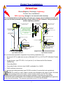
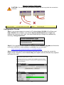
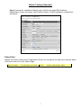
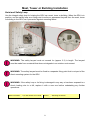
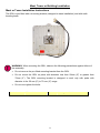
PTP 600 Series
Deployment Guide
Contents
Protect Your Installation .............................................................................................................................. 2
Checklist, Site Survey and Tools................................................................................................................. 4
Bench Testing (Optional)............................................................................................................................. 5
Mast, Tower or Building Installation ............................................................................................................ 8
Installation Wiring ...................................................................................................................................... 11
Cable Preparation and Installation ............................................................................................................ 12
Testing and Fault Finding (Troubleshooting)............................................................................................. 15
User Information to be Recorded .............................................................................................................. 18
Installation and Commissioning................................................................................................................. 19
Registration Warranty and Ordering Information....................................................................................... 22
1
Protect Your Installation
Attention
ElectroMagnetic Discharge (Lightning)
Protect Your Installation!
EMD (Lightning) damage is not covered under warranty.
The recommendations in this guide and in the user manual, when installed correctly, give
the user the best protection from the harmful effects of EMD. However 100% protection is
neither implied or possible.
ODU
Surge Arrestor
to ODU Ground
Connection
Optional Ethernet
Fibre connection to
ODU
LPU Surge Arrestor
to ODU Ground
Connection
LPU mounted at the same
height as the ODU
ODU
Ground connections should
be less than 0.6 metres
(2 feet) long. All upper
tower grounds should be
within 0.3 metres (1 foot) of
the ODU bracket and on the
same metal
Optional Ethernet Fibre
connection to ODU
Power/Ethernet
Connection
LPU Surge Arrestor
Screened CAT 5e cable
Screened CAT 5e cable
LPU Surge Arrestor
Grounding Cable
PIDU Plus
LPU Surge Arrestor
Fitted inside building
C opper Connection
to Network
PIDU Plus
Copper Connection to
Network
Fiber Connection to
Network
Where fitted
Fiber Connection to Network
Where fitted
Grounding Stakes
Grounding Stake
Typical Mast Installation
Typical Wall Installation
The recommended standard components for protecting installations are:
•
Screened CAT 5e cable also known as Shielded CAT 5e or CAT 5e STP (Shielded Twisted
Pair)
•
Surge Arrestor: type PTP-LPU: 4 or 8 per link (2 or 4 Motorola Kits Part Number
WB2907AA)
•
Grounding Stake
•
Grounding Cable: minimum size 8 AWG, preferably 6 or 4 AWG
•
RJ45 screened connectors
•
Andrew grounding assembly type 223158 or similar (if required by local regulations).
NOTE: If a coaxial (or other) cable is already cross-bonded to the mast or tower, the same
cross bonding points on the mast or tower must be used for the CAT 5e cable.
We recommend that the practices and procedures detailed in the Motorola manual R56
STANDARDS AND GUIDELINES FOR COMMUNICATION SITES (68P81089E50) be applied to
all new site build activities. This manual is provided on the PTP 600 CD-ROM.
2
Protect Your Installation
Lightning Protection Zones
When the ODU is installed on a mast, tower or wall, it may be in one of two possible lightning
protection zones:
•
Zone A: In this zone a direct lighting strike is possible. Do not mount the ODU in this zone.
•
Zone B: In this zone, direct EMD (Lightning) effects are still possible, but mounting in this
zone significantly reduces the possibility of a direct strike. Mount the ODU in this zone.
Finial
NOT Recommended
Recommended
Zone A
Zone A
Zone A
Zone B
Recommended
Zone B
Zone B
The following protection requirements are mandatory:
•
The ODU must be earthed
•
Screened CAT 5e cable must be used
•
Surge arrestors of type PTP-LPU must be installed at both the ODU and building entry
•
There must be an earth connection at building entry
More information:
PTP 600 Series User Guide
Section:
“Lightning Protection”
Additional Grounding Requirements for Connectorized ODU
Antenna cables should be grounded
within 0.3 metres (1 foot) of the ODU
and Antennas
Connectorized ODU
Antenna Cable
Grounded to Tower
Antenna Cable Grounded
to Tower.
Antenna Cable
Antenna Cable
Note: Antenna cables grounded using
an Andrew grounding assembly type
223158 or similar.
Antenna Cables
Grounded to Tower
Additional Grounding Requirements for Connectorized ODU
More information:
PTP 600 Series User Guide
Section:
3
“Connectorized PTP 600 Series Bridge”
Checklist, Site Survey and Tools
CAUTION: Before performing an installation of a Motorola PTP 600 Series system, ensure
that you have read this entire guide and taken note of any safety information contained.
Checklist
•
Check the contents of all packages against the packing list.
•
Check the Web site for the latest software load.
List of Special Tools Required
•
13mm wrench and 22 mm wrench for use with the glands
•
RJ45 crimp tool (it must be the correct tool for the type of RJ45 being used)
•
Personal Computer (PC) with 10, 100 or 1000 BaseT Ethernet
•
Either Internet Explorer version 6 or higher, or FireFox 2.0 or higher are recommended.
•
Ethernet patch cables
•
Motorola PTP LINKPlanner report for this link
More information:
PTP 600 Series User Guide
Section:
“Installation”
Pre-installation: Site Survey and Link Planning
A site survey must be performed to identify all the obstructions (such as trees or buildings) in the path and
to assess the risk of interference. This information is important if you are to achieve an accurate link
feasibility assessment.
The PTP 600 Series are designed to operate in Non-Line-of-Sight (NLoS) and Line-of-Sight (LoS)
environments. Link planning enables a link of known quality to be installed. This involves the acquisition of
path profile data (using Motorola’s free LINKPlanner utility). The LINKPlanner predicts data rates and
reliability over the path. It allows the user to try different antenna heights and RF power settings. When the
link is installed, the mean path loss can be checked to confirm that the predicted data rate and link reliability
is achievable. Motorola LINKPlanner is available to download from http://www.motorola.com/ptp/support.
More information:
PTP 600 Series User Guide
Section:
“Site Planning”
Pre-installation: License Keys and Regulatory Conformity
If the units have been purchased as a pair (link) then the License Keys (at the end of this guide or
printed on a separate card in the box) will show how the units have been pre-configured to work as
a link. Software, license key, unit IP address, subnet mask, gateway address, target address,
master/slave and arming state are pre-configured.
CAUTION: Check that the link is configured with the correct Region Code. If Region Code
is incorrect, then re-configure the units with Alternative License Keys before installing and
commissioning the link. Refer to “Configuration Checks” for details on how to change the
License Key.
More information:
PTP 600 Series User Guide
Section:
4
“Radio Link Planning and Regulations”
Bench Testing (Optional)
It is advised that the link be configured and tested on a bench before the final installation of the
units on a pole or a mast. The following steps give details of how to connect an ODU to a PC in
order to check the configuration details, change the IP settings or modify the license key. For the
purpose of these tests, normal off-the-shelf Ethernet cables can be used.
Power Checks
Step 1: Connect the RJ45 at
Step 2: Undo the retaining screw
one end of a cable to the ODU. of the PIDU Plus and hinge back
the cover.
Step 3: Plug in the ODU to
PIDU Plus Cable, ensuring
that it snaps home.
Step 4: Put the cover back
and tighten the screw.
Step 5: Plug in power lead using
a cable appropriate for the
installation.
Step 6: If the power LED
does not illuminate, remove
the power cable and the ODU
connection from the PIDU
Plus. Re-connect the power
lead and check the power
LED illumination (green). If
the power LED still does not
light then check the power
source.
Step 7: Connect a second
Ethernet cable (shown in
yellow) to the “LAN” socket of
the PIDU Plus.
Step 8: 45 seconds after
powering, the Ethernet LED
should be observed to flash
slowly 10 times. If the Ethernet
LED does not illuminate
(orange), then either the PIDU
Plus or the cable to the ODU
may be faulty. Replace cable
and/or PIDU Plus and repeat
from Step 1.
Step 9: Ensure PC is set to
correct IP address
169.254.1.x, where 2 < x <
254. Connect the LAN cable
to the PC.
Step 10: If it is necessary to
Step 11: Check that the Ethernet
use IP addresses 10.10.10.11 LED is now ON.
and 10.10.10.10, ensure that
the PC is configured with an IP
address of 10.10.10.n, where n
is any value between 2 and
254 but excluding 10 and 11,
to configure these units.
5
If this IP address is not
recognised, try 10.10.10.11
(Master) and 10.10.10.10
(Slave), as some units may
have been pre-configured
with these addresses.
Step 12: If the LED does not
show any activity when
accessing web pages, refer to
the Troubleshooting section
in this guide.
Bench Testing (Optional)
CAUTION: Do not dress the RJ45 cables too tightly, as this may make the connections
unreliable.
More information:
PTP 600 Series User Guide
Section:
“Connecting Up”
Configuration Checks
Step 1: Use a web browser to connect to IP address http://169.254.1.1 for Slave and
http://169.254.1.2 for Master units. Select System Administration and Login (the
password is empty for new units). We recommend that you change the password by
selecting “Change Password.
Step 2: If an upgrade to the software is required, select Software Upgrade and follow the
on-screen instruction. Latest software is available from our web site:
(http://motorola.motowi4solutions.com/software/#ptp)
Step 3: Check the License Key information and ensure you are using the correct the
Region Code. Otherwise, select License Key and replace with the alternate key supplied
and reboot the unit.
6
Bench Testing (Optional)
Step 4: Access the ‘Installation Wizard’ page. Confirm the target MAC Address,
Master/Slave choice, Symmetry, Max Transmit Power. Confirm installation configuration
and reboot.
Paired Unit
Repeat the Power Checks and Configuration Checks for the paired unit and check that the status
of the link shows UP on the ‘Status Page’.
More information:
PTP 600 Series User Guide
Section:
7
“System Administration Pages”
Mast, Tower or Building Installation
Hoist and Safety Loop
Use the integral safety loop for hoisting the ODU up a mast, tower or building. When the ODU is in
position, use the safety loop as a fixing point to secure a permanent lanyard from the mast, tower
or building to the ODU, as a precaution against mounting failure.
WARNING: The safety lanyard must not exceed 1m (approx 3 ft) in length. The lanyard
must be made from a material that does not degrade in an outdoor environment.
WARNING: The safety lanyard must be fixed to a separate fixing point that is not part of the
direct mounting system for the ODU.
WARNING: If the safety loop or its fixing is damaged in any way or has been exposed to a
shock loading due to a fall, replace it with a new one before undertaking any further
operations.
More information:
PTP 600 Series User Guide
Section:
8
“Mounting the ODUs”
Mast, Tower or Building Installation
Mast or Tower Installation Instructions
The ODU is pre-fitted with a mounting bracket (designed to ease installation) and with earth
bonding leads.
WARNING: When mounting the ODU, observe the following precautions against failure of
the assembly:
•
Do not remove the pre-fitted mounting bracket from the ODU.
•
Do not mount the ODU on poles with diameter less than 50mm (2”) or greater than
75mm (3”). The ODU mounting bracket is designed to work only with poles with
diameter in the 50 mm (2”) to 75 mm (3”) range.
•
Do not over-tighten the bolts.
More information:
PTP 600 Series User Guide
Section:
9
“Mounting the ODUs”
Mast, Tower or Building Installation
The ODU must be mounted using the following steps, with cable entry at the bottom:
Step 1: Attach the bracket strap to the pole
using M8 x 70 mm bolts, M8 flat washers and
M8 coil washers. Tighten to ensure the
assembly grips but can be adjusted.
Step 2: Offer the ODU (with pre-fitted
mounting bracket) to the bracket strap and
affix using the captive M8 bolt.
Step 3: Adjust the elevation and azimuth of
the unit before tightening to the required
torque settings of 14 Nm (11 lbft) for both
bolts.
Step 4: Attach the free end of one earth
bonding lead (large tag M10) to the tower
metal work.
Tighten to ensure the assembly grips, but can
be adjusted on the pole.
CAUTION:
On no account must this be attached
to the mounting bracket bolts.
WARNING: A cable measuring card must NEVER be used at the ODU end connected to power
from the PIDU. It must only be used at the bottom of the mast with a multimeter. This is because
the PIDU voltage exceeds the limit allowed in some countries for safe handling in wet conditions and
therefore may create a safety hazard.
More information:
PTP 600 Series User Guide
Section:
10
“Mounting the ODUs”
Installation Wiring
Motorola PTP 600 Series Installation Wiring
All upper tower
grounds should be
within 0.3 metres of the
ODU bracket and on
the same metal
PTP 58600 ODU
+55V and
LED/Reset
Signalling
Ethernet
Ethernet
Ethernet
Ethernet
Chassis
1 Orange/White
2 Orange
3 Green/White
6 Green
4 Blue
5 Blue/White
7 Brown/White
8 Brown
Cable to LPU & ODU
grounding by means
of the grounding
glands provided
0V
RJ45
RJ45
PTP LPU
P8 P7
8
7
P5 P4
5
4
P6 P3
P2 P1
6
2
3
1
Grounding
cables provided
RJ45
There may be a local regulatory
requirement to cross bond the
CAT 5e cable to the mast at
intervals as regular as every 10
metres. This can be achieved
using an Andrew grounding
assembly type 223158 or
similar.
Cable to LPU
grounding by means
of the grounding
glands provided
Ethernet
Cabling
to T-568B
RJ45
PTP LPU
P8 P7
8
7
P5 P4
5
4
P6 P3
P2 P1
6
2
3
1
RJ45
Inside Building
RJ45
1 Orange/White
Ethernet
2 Orange
3 Green/White
Ethernet
6 Green
4 Blue
5 Blue/White
8 Brown
7 Brown/White
Ethernet
PIDU
Plus
Figure 1 Motorola PTP 600
Series Simplified Circuit and
Grounding requirements
Ethernet
0V
+55V and
LED/Reset
Signalling
More information:
PTP 600 Series User Guide
Section:
11
“Lightning Protection”
Cable Preparation and Installation
The maximum cable length between the ODU and the user’s Network Equipment is 100m (330 ft).
Cable lengths up to 300m (984 ft) can be used where the PIDU Plus to ODU cable is supplying
power only, that is, when using the PTP 600 Series Bridge Optical Interface
Correct Cable Preparation for the Recommended Cable
CAUTION: Check that the crimp tool matches the RJ45 connector being used.
More information:
PTP 600 Series User Guide
Section:
12
“Connecting Up”
Cable Preparation and Installation
Cable and Gland Installation
To install the cables and glands, follow these steps:
Step 1: Make a cable as specified in “Cable
Preparation”. Plug in the RJ 45 into the ODU.
Step 2: Support the drop cable and gently hand
screw the gland body into the ODU until the O
ring seal is flush to the ODU body.
Caution:
Do not fit the back shell prior to securing
the gland body.
Step 3: Once the gland is fully hand screwed
into the ODU it may be tightened to a torque of
7 ftlbs/10Nm, with a 22mm wrench.
Step 4: When the gland body has been fitted,
tighten the gland back shell.
Caution:
Do not over tighten the gland back shell.
The gland on the right-hand side has been over
tightened. As a result, the internal seal and
structure have been damaged:
Step 5: Should it be necessary to disconnect
the cable at the ODU (or PTP LPU), this can be
achieved by removing the gland back shell first.
Then, wiggle the cable to release the tension of
the gland body as shown in the figure below.
Then you can unscrew the gland body and
depress the RJ45 locking tab with a small
screwdriver.
This is illustrated below.
13
Cable Preparation and Installation
Apply small movements to the cable until you see a gap here before
unscrewing the gland body.
More information:
PTP 600 Series User Guide
Section:
14
“Connecting Up”
Testing and Fault Finding (Troubleshooting)
Perform troubleshooting (fault finding) procedures either on a newly installed link, or on an
operational link if communication is lost.
When the link end hardware (PIDU, LPU, ODU and cabling) has been installed, start it by following
this procedure:
Step 1: Connect the RJ45 from the ODU (or LPU if fitted) to the PIDU and apply mains or
battery power to the PIDU. The green Power LED should illuminate continuously.
Step 2: After 45 seconds, the yellow Ethernet LED should be observed starting with 10 slow
flashes.
Step 3: Connect the RJ45 from the LAN port of the PIDU to the network. The yellow
Ethernet LED should blink randomly as traffic passes through.
If the Power and Ethernet LEDs do not illuminate correctly, test the link end as described in this
flowchart (references such as (*1) are to the tests on the following pages):
Start
Is the green
power LED
on solid?
No
No
Is the power
LED
flashing?
(*1) Power LED
is Off
Yes
Yes
Did the
Ethernet
LED flash 10
times?
(*2) Power LED
Flashes
No
(*3) Ethernet LED
did not Flash 10
Times
Yes
Is Ethernet
activity now
normal?
No
No
Is there any
Ethernet
activity?
(*4) No
Ethernet
Activity
Yes
Yes
(*5) Irregular
Ethernet
Activity
Is Ethernet
connection
1000 BaseT?
No
(*6) Connection is
not 1000 BaseT
Yes
(*7) Test RJ45
Resistance
15
Testing and Fault Finding (Troubleshooting)
(*1) Power LED is Off
Unplug the ODU connection from the PIDU and check the power LED illumination. If the
power LED still does not light then check the power source.
(*2) Power LED is Flashing
Check that pins 4&5 and 7&8 are not crossed with pins 1&2 and 3&6 on the RJ45, and also
greater than 100K ohms between pins 1&8.
(*3) Ethernet LED did not Flash 10 Times
Check that the wiring to pins 4&5 and 7&8 is correct. For example, the wiring to pins 4 and
7 may be crossed.
(*4) No Ethernet Activity
Check that the wiring to pins 1&2 and 4&6 is correct. For example, the wiring to pins 1 and
3 may be crossed.
(*5) Irregular Ethernet Activity
The yellow Ethernet LED should blink randomly as normal traffic passes through. If the
Ethernet LED flashes irregularly, for example there is a short flash followed by a long flash,
this indicates that the ODU has booted in recovery mode. The causes may be installation
wiring or a corrupt ODU software load.
(*6) Connection is not 1000 BaseT
If the Ethernet connection to the network is only 10/100 BaseT, when 1000 BaseT is
expected, check that the wiring to pins 4&5 and 7&8 is correct. For example, the wiring to
pins 4 and 7 may be crossed.
(*7) Test RJ45 Resistance
If the above tests fail to diagnose the issue, there may be a fault in the wiring of the RJ45
cable that connects the ODU (or LPU) to the PIDU. Perform the following tests:
Step 1: Unplug the RJ45 cable from the PIDU and check that the resistances
between pins are correct as specified in Table 1.
Resistances should fall within + or -10% of the stated values.
Step 2: Ensure that there is greater than 100K ohms between pin 1 and ODU ground
for all cable lengths.
Step 3: Ensure that there is greater than 100K ohms between pin 8 and ODU ground
for all cable lengths.
Step 4: If GPS is not fitted, ensure that there is greater than 100K ohms between pin
1 and pin 8 for all cable lengths. If GPS is fitted, ensure there is greater than 2K
ohms between pin 1 and pin 8.
If a GPS Synchronization Box has been installed, but one or more of its status LEDs are not
illuminated, refer to “Test GPS Synchronization Box” in the User Guide.
More information:
PTP 600 Series User Guide
Section:
16
“Troubleshooting (Fault Finding)”
Testing and Fault Finding (Troubleshooting)
Table 1 - Resistance Table Referenced to the RJ45 at the PIDU
Resistances should fall within + or -10% of the stated values.
CAT-5
Length
(Meters)
Resistance between
pins 1&2, 3&6 , 4&5 and
pins 7&8 (ohms)
Resistance between
pins 1&3 (ohms)
Resistance
between pins 4&7
(ohms)
0
0.8
1.0
1.6
10
2.7
2.7
3.3
20
4.6
4.4
5.0
30
6.5
6.1
6.7
40
8.3
7.8
8.4
50
10.2
9.5
10.1
60
12.1
11.2
11.8
70
14.0
12.9
13.5
80
15.8
14.6
15.2
90
17.7
16.3
16.9
100
19.6
18.0
18.6
150
29.0
26.5
27.1
200
38.4
35.0
35.6
250
47.7
43.5
44.1
300
57.1
52.0
52.6
More information:
PTP 600 Series User Guide
Section:
17
“Troubleshooting (Fault Finding)”
User Information to be Recorded
Use Table 2 and Table 3 to record the specified information. This information will be useful if there
is a need to contact Motorola support or to identify future changes in the installation.
Table 2 – Resistance Values
Measure
Resistance
Between Pins
Measured
Measured
Resistance
Value
Resistance
Value
LOCAL
REMOTE
1&2
3&6
4&5
7&8
1&3
4&7
1&8
1&ODU Ground
8&ODU Ground
Table 3 – Link Identification
LOCAL
REMOTE
IP Address
Link Name
MAC Address
User Notes
18
Installation and Commissioning
Aligning the PTP 600 Series Bridge ODUs
The PTP 600 Series Bridge uses audible tones during installation to assist the installer with
alignment. The installer should adjust the alignment of the ODU in both azimuth and elevation until
highest pitch tone is achieved.
The pitch of the alignment tone is proportional to the received power of the wireless signals. The
best results are usually achieved by making small incremental movement in angular alignment.
The tones and their meanings are as follows:
State Name
Tone
Description
State
Description
Pitch Indication (Higher
pitch = higher power)
Free Channel
Search
Regular beep
Executing band
scan
N/A
Scanning
Slow broken tone
Not demodulating
the wanted signal
Rx Power
Synchronized
Fast broken tone
Demodulating the
wanted signal
Rx Power
Registered
Solid tone
Both Master and
Rx Power
Slave units
exchanging Radio
layer MAC
management
messages
The term ‘wanted signal’ refers to that of the peer unit being installed.
In each of the states detailed above, the unit should be aligned to give the highest pitch tone. It
should be noted that if, when in the Synchronized or Registered state, the tone varies wildly, you
may be suffering from interference or a fast fading link. Installing in this situation may not give a
reliable link. The cause of the problem should be investigated.
For the ease of alignment, both Master and Slave units use the install tones in the same way but
with some small behavioral differences. This allows the installer to install the Slave unit first and
carry out the initial alignment with the Master unit if desired. However, due to the behavioral
differences of Master and Slave units, it is recommended that the Master unit is installed first and
the initial alignment carried out at the Slave unit.
Once the optimum performance has been achieved by directing the Slave unit (indicated by
highest frequency of tone) then adjustment of the direction of the Master unit should be done
without moving the Slave. Repeat if necessary at the Slave and then the Master until optimum
alignment has been obtained.
More information:
PTP 600 Series User Guide
Section:
19
“Establishing a Radio Link”
Installation and Commissioning
Behaviour During Installation
The following behavior should be noted:
•
Band scan: When first started up and from time to time, the Master unit will carry out a band
scan to determine which channels are not in use. During this time, between 10 and 15
seconds, the Master unit will not transmit and as a consequence of this neither will the Slave
unit. During this time the installation tone on the master unit will drop back to the band scan
state, and the Slave unit will drop back to the Scanning state with the pitch of the tone set to
the background noise level. Alignment of the unit should cease during this time.
•
Radar detection: If the unit is operating where mandatory radar avoidance algorithms are
implemented, the ranging behaviour for the PTP 600 Series Bridge may be affected. The
Master has to monitor the initially chosen channel for 60 seconds to make sure it is clear of
radar signals before transmitting. If a radar is detected during any of the installation phases,
a further compulsory 60 seconds channel scan will take place as the master unit attempts to
locate a new channel that is free of radar interference.
•
Ranging: The Master unit can take up to 60 seconds in 0-40km (0-25 miles) mode, 90
seconds in 0-130km (0-81 miles) mode and 120 seconds in 0-200km (0-124 miles) mode to
determine the range of the link being installed. The Master unit will remain in the Scanning
state until the range of the link has been established. The Master unit will only move to the
Synchronized state when the range of the link has been established.
•
Retrying same channel: If, at the end of the ranging period, the Registered state is not
achieved due to interference or other reasons, the Master unit will retry twice more on the
same channel before moving to another available channel. Should this occur it might take a
number of minutes to establish a link in the Registered state.
•
Slave unit: The Slave unit does not have a ranging process. The slave unit will change to
the Synchronized state as soon as the wanted signal is demodulated.
More information:
PTP 600 Series User Guide
Section:
20
“Establishing a Radio Link”
Installation and Commissioning
Adjust Power Settings
The transmit power levels of the installed units must be adjusted to ensure they are not too high.
Excessive power levels may cause saturation of the receivers or false radar detection (in radar
enabled regions), leading to degradation of link performance and link failure. To adjust power
levels, follow this procedure:
Step 1: Consult the report generated by the LINKPlanner tool and note the Transmit power
recommended levels.
Step 2: Set the local unit power equal to the “LOCAL - Max Transmit Power setting while
pointing” value from the LINKPlanner report.
Step 3: Set the remote unit power equal to the “REMOTE - Max Transmit Power setting
while pointing” value from the LINKPlanner report.
Step 4: Access each unit separately.
Step 5: Align the units.
Step 6: Repeat Step 2 and 3 using the values “LOCAL - Max Transmit Power setting
before disarm” and “REMOTE - Max Transmit Power setting before disarm” , if different
than the corresponding “while pointing” values.
Step 7: Reboot the local unit then reboot the remote unit.
Step 8: Disarm the units.
Disarm on Completion
When the alignment process is complete, the installer MUST REMEMBER TO DISARM BOTH
UNITS in the link. This is necessary in order to:
•
Turn off the audible alignment aid.
•
Enable Adaptive Modulation
•
Fully enable Advanced Spectrum Management with i-DFS
•
Clear unwanted installation information from the various systems statistics
•
Store the link range for fast link acquisition on link drop
•
Enable higher data rates
Items for Future Reference
Take note of the following items for future reference:
•
Save a copy of the configuration using the “Save and Restore” functionality found under the
“System Administration – Configuration” menu.
•
Take a screen shot or print of the status page.
•
Note the position and orientation of the antenna.
•
Note surrounding objects that may interfere with the link (a photograph is recommended).
•
After 1 hour of operation, the mean value of Link Loss on the status page should be within
the values given in the LINKPlanner report. Further adjustments of the power levels may be
necessary, so consult the LINKPlanner report notes and adjust the powers accordingly. You
will be required to reboot the units for that to take effect.
•
The LINKPlanner may need re-running to account for new known obstacles any time during
the operation of the link.
21
Registration Warranty and Ordering Information
The PTP600 is an extraordinarily robust radio communications link with unsurpassed availability
and reliability. Along with your Motorola PTP Bridge you get a 12-month Standard Warranty that
provides a 30-day repair-and-replacement program for hardware defect failures and minor
software enhancements as they become available.
Although our bridges are extremely robust even in severe weather conditions, equipment failures
can occur. We, therefore, recommend that you consider upgrading your first-year Standard
Warranty to a PTP Extended or PTP “All Risk” Advanced Replacement Warranty. Extended
Warranty extends your initial 12-month standard hardware warranty through the second, third or
fifth years of ownership, providing 30-day repair and return for defective parts.
Advanced Replacement Warranty proposes up to five years of cover with next-business-day
shipping of replacement equipment. Our Advanced Replacement warranties provide “All Risks”
cover including:
•
Lightning Damage.
•
Damage – caused by improper wiring, electrical shorts, building fires, vandalism.
•
Dropped Units.
•
Component or manufacturing defects.
With our warranties, you have peace-of-mind knowing that your investment is fully protected and, if
you are covered with the Advanced Replacement Warranty, your communications will be back in
operation in the shortest time possible.
Register Your Units to receive updates and activate your warranty
Upon receipt of your new PTP link, you should register your units to activate your free standard 12month warranty and receive notification of software updates. For convenience, you can do that
online at www.motorola.com/ptp/support/registration.
Item
Part Number
1 Year PTP Software Support Contract (1-2 Links)
WB3106
1 Year PTP Software Support Contract (3-5 Links)
WB3107
1 Year PTP Software Support Contract (5+ Links)
WB3108
2nd Year Extended Year (30 Day Return & Repair)
WB2530
3rd Year Extended Year (30 Day Return & Repair)
WB2531
5th Year Extended Year (30 Day Return & Repair)
WB2590
Upgrade 1st year 24hr Advanced Replacement “All Risks”
WB2532
Upgrade 2nd year 24hr Advanced Replacement “All Risks”
WB2533
Upgrade 3rd year 24hr Advanced Replacement “All Risks”
WB2534
Upgrade 5th year 24hr Advanced Replacement “All Risks”
WB2591
22
License Keys and Regulatory Information
Motorola, Inc.,
1303 E. Algonquin Road,
Schaumburg,
Illinois 60196
U.S.A
Telephone Support: +1 866-961-9288
http://www.motorola.com/ptp/support
MOTOROLA, the stylized M Logo and all other trademarks indicated
as such herein are trademarks of Motorola, Inc. ® Reg. US Pat & Tm.
Office. All other product or service names are the property of their
respective owners.
Doc Ref: phn1189_009v000
© 2006-2009 Motorola, Inc. All rights reserved.
23