1
UFC 4-510-01
16 October 2003
ED
UNIFIED FACILITIES CRITERIA (UFC)
C
AN
C
EL
L
DESIGN: MEDICAL MILITARY
FACILITIES
APPROVED FOR PUBLIC RELEASE; DISTRIBUTION UNLIMITED
UFC 4-510-01
16 October 2003
UNIFIED FACILITIES CRITERIA (UFC)
MEDICAL MILITARY FACILITIES
ED
Any copyrighted material included in this UFC is identified at its point of use.
Use of the copyrighted material apart from this UFC must have the permission of the copyright
holder.
DEFENSE MEDICAL FACILITIES OFFICE (Preparing Activity)
U.S. ARMY CORPS OF ENGINEERS
EL
L
NAVAL FACILITIES ENGINEERING COMMAND
AIR FORCE CIVIL ENGINEER SUPPORT AGENCY
Record of Changes (changes are indicated by \1\ ... /1/)
Date
Location
C
AN
C
Change No.
This is a republication of Military Handbook 1191 (2002) as a Unified Facilities
Criteria document.
UFC 4-510-01
16 October 2003
FOREWORD
The Unified Facilities Criteria (UFC) system is prescribed by MIL-STD 3007 and provides
planning, design, construction, sustainment, restoration, and modernization criteria, and applies
to the Military Departments, the Defense Agencies, and the DoD Field Activities in accordance
with USD(AT&L) Memorandum dated 29 May 2002. UFC will be used for all DoD projects and
work for other customers where appropriate. All construction outside of the United States is
also governed by Status of forces Agreements (SOFA), Host Nation Funded Construction
Agreements (HNFA), and in some instances, Bilateral Infrastructure Agreements (BIA.)
Therefore, the acquisition team must ensure compliance with the more stringent of the UFC, the
SOFA, the HNFA, and the BIA, as applicable.
EL
L
ED
UFC are living documents and will be periodically reviewed, updated, and made available to
users as part of the Services’ responsibility for providing technical criteria for military
construction. Headquarters, U.S. Army Corps of Engineers (HQUSACE), Naval Facilities
Engineering Command (NAVFAC), and Air Force Civil Engineer Support Agency (AFCESA) are
responsible for administration of the UFC system. Defense agencies should contact the
preparing service for document interpretation and improvements. Technical content of UFC is
the responsibility of the cognizant DoD working group. Recommended changes with supporting
rationale should be sent to the respective service proponent office by the following electronic
form: Criteria Change Request (CCR). The form is also accessible from the Internet sites listed
below.
UFC are effective upon issuance and are distributed only in electronic media from the following
source:
•
Whole Building Design Guide web site http://dod.wbdg.org/.
AN
AUTHORIZED BY:
C
Hard copies of UFC printed from electronic media should be checked against the current
electronic version prior to use to ensure that they are current.
C
______________________________________
DONALD L. BASHAM, P.E.
Chief, Engineering and Construction
U.S. Army Corps of Engineers
______________________________________
KATHLEEN I. FERGUSON, P.E.
The Deputy Civil Engineer
DCS/Installations & Logistics
Department of the Air Force
______________________________________
DR. JAMES W WRIGHT, P.E.
Chief Engineer
Naval Facilities Engineering Command
______________________________________
Dr. GET W. MOY, P.E.
Director, Installations Requirements and
Management
Office of the Deputy Under Secretary of Defense
(Installations and Environment)
MIL-HDBK-1191
FINAL, 09 JULY 02
MILITARY HANDBOOK
C
AN
C
EL
L
ED
DEPARTMENT OF DEFENSE
MEDICAL MILTARY FACILITIES
DESIGN AND CONSTRUCTION CRTIERIA
I
MIL-HDBK-1191
FINAL, 09 JULY 02
ABSTRACT
This handbook provides mandatory design and construction criteria for
facilities in the DoD Medical Military Construction Program.
These
criteria are also applicable to military medical facilities funded by
other programs, under limitations discussed in Section 1. Servicespecific criteria may augment this handbook, but requirements that
exceed this guidance must be fully justified to ensure understanding by
the reviewing officials.
ED
For MILCON projects, the procedures outlined in this handbook apply
from the time the Design Authorization (DA) is issued by the Defense
Medical
Facilities
Office
(DMFO)
and
throughout
the
design,
construction, Beneficial Occupancy, and the Post-Occupancy Evaluation
(POE) period.
C
AN
C
EL
L
While these criteria were not developed primarily for use in review of
military construction program and budget submissions, it is recognized
they may be used for that purpose.
Projects should not, however, be
approved, disapproved, or justified solely on the basis of these
criteria.
II
MIL-HDBK-1191
FINAL, 09 JULY 02
FORWARD
This handbook is issued under the authority of DoD Directive 6015.17,
“Procedures for the Planning, Programming, Budgeting, and Execution for
Construction of Military Health Facilities”, dated April 15, 1986,
which gave the Defense Medical Facilities Office (TMA-DMFO) the
authority to develop and maintain the facilities planning, design, and
construction criteria in support of the missions of the Military Health
Services System.
ED
This handbook applies to the Office of the Secretary of Defense (OSD),
the Military Departments, the Organization of the joint Chiefs of Staff
(OJCS), the Unified and Specified Commands, the Defense Agencies, and
activities administratively supported by OSD (hereafter referred to
collectively as “DoD Components”).
This handbook covers criteria
unique to Category Code 171, 310, and 500 facilities only and shal be
used in conjunction with the MIL-HDBK-1190, “Facility Planning and
Design Guide”, for general building requirements.
C
EL
L
The Defense Medical Facilities Office (TMA-DMFO), 5205 Leesburg Pike,
Suite 100, Skyline 1, Falls Church, VA
22041-3208, is the Office of
Primary Responsibility (OPR) for approval of this handbook.
The U.S.
Army Corps of Engineers’ Medical Facilities Center of Expertise is the
Executive
Agent
responsible
for
maintenance
of
the
Handbook.
Recommendations for improvement to this handbook are encouraged and
should be reported on the DoD Form 1426 provided inside the back cover
to the U.S. Army Corps of Engineers, CEHNC-MX, Humphreys Engineer
Center, 7701 Telegraph Road, Room 2A-16, Alexandria, VA
22315-3813,
with information copy to TMA-DMFO.
The using Military Departments and
the Design and Construction Agents may submit proposed changes to this
handbook through the Healthcare Facilities Steering Committee and TMADMFO as provided at Section 01 of this handbook.
C
AN
This handbook shall not be used as a reference document for procurement
of facilities construction.
It is to be used in the purchase of
facilities engineering studies and design (plans, specifications, and
cost estimates).
III
MIL-HDBK-1191
FINAL, 09 JULY 02
TABLE OF CONTENTS
Appendix
Appendix
Appendix
Appendix
A:
B:
C:
D:
ED
Individual Room Design Requirements and Conditions.
Design Submittals and Documentation Guideline.
Universal X-Ray Room.
UFAS Interpretations and Waivers.
Glossary of Terms, Abbreviations, and Acronyms.
C
AN
Glossary:
General Design Guidance.
Design Procedure, Submittals, and Documentation.
Master Planning and Site.
Architecture.
Structural.
Seismic.
Energy and Water Conscious Design.
Heating, Ventilating, and Air Conditioning.
Plumbing and Medical Gases.
Electrical.
Communications.
Accessibility.
Fire Protection.
Security.
Force Protection.
Medical and Dental Equipment.
Conveyance Systems.
Waste Management.
Integrated Building Systems.
Construction.
Signage.
Food Service.
Acoustics.
EL
L
01:
02:
03:
04:
05:
06:
07:
08:
09:
10:
11:
12:
13:
14:
15:
16:
17:
18:
19:
20:
21:
22:
23:
C
Section
Section
Section
Section
Section
Section
Section
Section
Section
Section
Section
Section
Section
Section
Section
Section
Section
Section
Section
Section
Section
Section
Section
IV
MIL-HDBK-1191
SECTION 1:
GENERAL GUIDANCE
ED
1.1 General. This section provides general guidance on Department of
Defense (DoD) policies and procedures for design and construction of
Defense Medical Facilities, including medical and dental treatment
facilities (MTF's), medical training facilities, medical research
facilities, and veterinary treatment facilities in the Defense Medical
Program.
When feasible, this document is also to be utilized as
criteria in the addition, alteration, or service upgrade to existing U.S.
Military medical facilities funded by military departmental programs.
Subject to the restrictions provided herein; applicability shall be
limited only to those portions of such facilities, and/or the
corresponding support services, specifically referenced by the project
authorization document. It is the DoD objective to provide facilities
that are responsive to the functional requirements of the using Military
Department.
AN
C
EL
L
1.2 Applicability. This document sets forth DoD policy, procedures,
and technical criteria for the design and construction of facilities in
the Department of Defense Medical (DoDM) Military Construction (MILCON)
program, and other medical design and construction projects over
$500,000. When feasible, the technical criteria in this document shall
be the basis of design for Operations and Maintenance (O&M) or Repair
and Maintenance (R&M) work, though the specific submittal and approval
requirements may vary for those types of projects. In overseas
locations where either Status of Forces Agreements (SOFA), local host
country codes and standards, or other local circumstances may conflict
with the criteria in this handbook, alternate design approaches shall
be developed to achieve the intent of the criteria without compromising
life safety or the safeguarding of persons and property. Conflicts
shall be resolved at the Design Agent level, when the Design Agent’s
medical facilities design office or center of expertise determines that
resolution does not represent a significant change to criteria
affecting building occupant safety or health. All other proposed
changes shall be coordinated through the Design Agent’s medical office
or center for submission to the Healthcare Facilities Steering
Committee.
C
1.3 Policy. As stated in the DoD Directive 6015.17 (reference 1L), it
is DoD policy to design efficient, economical, and safe facilities, which
sustain an effective combat force, that support the DoD medical wartime
mission, and that meet the provisions of Title 10, United States Code
(reference 1a). This document prescribes the DOD technical criteria and
policy guidance for the design and construction of safe, functional, and
durable facilities, which will have reasonable and appropriate
maintenance and operations, costs throughout their designed life.
Detailed design criteria and procedures, which may be developed and
issued by the DoD Components (Military Departments), shall be consistent
with the policy statements and criteria contained herein and shall not
deviate these criteria without TMA/DMFO approval, as provided at 1.4.3.
Facility designs shall:
1.3.1 Meet the operating requirements of the using activity and provide
reasonable flexibility to accommodate future changes.
1-1
MIL-HDBK-1191
1.3.2 Provide functional facilities at the most economical and
practicable life-cycle-cost.
1.3.3 Be aesthetically compatible with the local environs and meet
necessary environmental requirements including applicable federal, state,
and local environmental standards and criteria. Necessary coordination
shall be maintained with the state and local community in accordance with
the requirements of E.O. 12372 (reference 1c) as implemented by DoD
Directive 4165.61 (reference 1d).
C
EL
L
ED
1.4 Responsibilities. The Office of the Assistant Secretary of Defense
(Health Affairs), OASD(HA), Tricare Management Activity (TMA), Defense
Medical Facilities Office (DMFO) is responsible for medical facility
policy and planning, and is the office having primary responsibility for
preparing and maintaining healthcare facility criteria. The Medical
Military Construction Operations (MMCO) is responsible for programming
medical military construction projects and managing financial resources
for planning, design and construction. TMA/DMFO is also responsible to
review those portions of DoD Medical MILCON concept level designs
described in Section 02 of this document, and to certify these designs in
accordance with DoD Directives 5136.12 and 6015.17 (references 1e and
1l). The Design and Construction Agents may maintain supplementary
technical criteria and will execute design and construction following
established regulations and procedures unless otherwise directed by the
TMA/DMFO. Design Agents will produce designs for a complete and useable
facility within the approved programmed scope and programmed amount. The
Military Departments as the users are responsible for all medical
functional review and input during design. The Functional User's and the
Service’s Design Agent’s responsibilities often overlap but do not
supersede the respective medical and technical role of the other; the
design of each facility must be a collaborative partnership. Specific
responsibilities are addressed in various sections of this handbook.
AN
1.4.1 Responsible Office. The Office of the Assistant Secretary of
Defense (Health Affairs), OASD(HA), TMA/DMFO is responsible for the
general administrative management of this entire document, and has
responsibility for the contents and development of criteria in
collaboration with the Healthcare Facilities Steering Committee (See
below).
C
1.4.2 Healthcare Facilities Steering Committee (HFSC). The HFSC acts as
the body responsible for the technical contents of this document. This
Committee is composed of members of TMA, the using Military Departments,
and the Service’s design agents actively involved in the planning,
programming, design, and construction of facilities. All proposed MILHDBK-1191 criteria updates and changes may be formally submitted to the
Committee for evaluation. DD Form 1426 is provided for this purpose at
the end of this MIL-HDBK-1191.
1.4.3 Waivers. TMA/DMFO has final authority to waive MIL-HDBK-1191
policy, procedures, or criteria including any deviations. Requests for
project specific waivers to any portion of this document must be
submitted in writing by the Design Agent, with full particulars and
justification, and must be fully coordinated with the using Military
Department.
1-2
MIL-HDBK-1191
1.4.4 Design/Construction Agents. As designated by the Secretary of
Defense (SECDEF) for certain geographical locations, Design/Construction
Agents are responsible for the execution of projects from receipt of a
Design Authorization from TMA/DMFO through the completion of
construction.
Design/Construction Agents are:
ED
a) The U. S. Army Corps of Engineers (USACE). The
Headquarters, USACE, Defense Agencies and Support For Others Branch
(CEMP-MD) is the primary USACE point of contact with OASD(HA) and is
responsible for all program management issues. The USACE Medical
Facilities Center of Expertise, Huntsville Engineering and Support Center
(CEHNC-MX) is USACE's technical expert for medical design, with
responsibility for concept design oversight, medical technical review of
final designs, and medical design guidance, criteria, and standards.
EL
L
b) The Naval Facilities Engineering Command (NAVFAC). The
NAVFAC Medical Facilities Design Office (MFDO) is the Navy's point of
contact with OASD(HA)and technical expert for medical design and NAVFAC's
final decision making authority regarding technical guidance, criteria,
and standards on all medical projects from initiation of project to
beneficial occupancy of the building.
c) The Air Force Civil Engineers (AF/ILECM). Air Force
Civil Engineering Directorate of Engineering is the primary point of
contact with OASD(HA) in the United Kingdom.
AN
C
1.5 Referenced Documents. The DoD Directives, Instructions, and
selected technical data, publications and standards (latest or most
current editions) are referenced in the text by basic designation only
and form a part of these criteria to the extent required by these
references. Where references are made to MIL-HDBK-1190 (reference 1f),
those referenced sections shall become an integral portion of this
guidance.
1.6 Restrictions. This handbook is not to be used as a reference
document for procurement of facilities construction. It is to be used in
the acquisition of Military Medical Facilities engineering studies and
designs (final plans, specifications, and cost estimates).
C
1.7 Predesign Considerations. Using Service, in coordination with
TMA/DMFO and as funded by the using service, will prepare a Project
Planning Package prior to the start of design. This package shall
include the following documents and information, provided to TMA-DMFO by
the Using Service in accordance with the DoD Medical Military
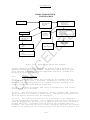
Construction Timeline, Figure 2-1:
1.7.1 DD Form 1391. Describes the scope, cost, type of construction and
the rationale for the project.
1.7.2 Project Narrative. Summarizes the sizing decision process, siting,
construction scenario, significant planning information and results.
1-3
MIL-HDBK-1191
1.7.3 Economic Analysis (EA). The Using Service will provide an
economic analysis as supporting justification of DOD medical projects
with a cost over $2 million, in accordance with guidance developed by the
Healthcare Facilities Steering Committee. The Economic Analysis compares
mission-based alternatives and identifies the most cost-effective capital
investment.
Specific requirements for the EA are contained in DoDI
6015.17 (Reference 1l).
1.7.4 Program for Design (PFD). Include the estimated number of parking
spaces as part of the Space Program.
EL
L
ED
1.7.5 Equipment Planning. The Using Service is responsible for
preparing an equipment list for installed medical and dental equipment,
and the associated budgeting, to support this requirement (MILCON) based
on the Space and Equipment Planning System (SEPS). Equipment in
Logistical category Codes E and F may be altered by the using Military
Department if funding source requirements are not exceeded. Any increase
in the funding for category Codes E and F equipment over the programmed
amount of the project requires TMA/DMFO approval.
1.7.6 Project Book (PB). The PB summarizes existing site conditions and
utilities, including the following minimum information.
C
a) Completed site survey (Example format is provided in
Figure 1-1),area maps, location maps, site location, site description (to
include grades, gates, etc), any/all demolition requirements on or near
the site, style of architecture, construction season limitations,
seismic, wind and snow considerations, SOFA, host country agreements,
soil and foundation conditions, utility conditions (water, sewer, power,
steam, electrical capacities and location), and site restrictions
(airfield, AICUZ potential helipad approach/departure zone obstructions,
floodland, rights-of-way, etc.), site security restrictions, the National
Capital Planning Commission (NCPC).
AN
b) Utility availability, including water, sewage, storm
drainage, electrical power, existing fuel sources, central heat or
chilled water systems, including the tap-in locations. Also include the
available capacities, power service characteristics and locations,
electrical distribution, water and wastewater considerations.
C
c) Environmental impact requirements, archaeological and
historical considerations, explosive ordinance locations, contaminated
soil (fuel, asbestos, etc.), coastal zone considerations, wetlands and
watershed considerations, threatened and endangered species
considerations, water quality, air quality, asbestos contamination,
protection of natural resources information, and any other Environmental
Protection Agency (EPA) or Occupational Safety and Health Administration
(OSHA) considerations necessary which might impact the MILCON project.
d)
Force Protection/Security requirements including
contingency considerations and statement by installation commander of
designee identifying appropriate threat security level wherever minimal
requirements are exceeded.
1-4
MIL-HDBK-1191
e)
Contingency mode concept of operation where applicable.
f)
water supply.
Fire protection considerations, such as accessibility and
ED
g) Communications Information or data systems, telephone and
signal interface requirements for fire, police, etc., telephone switch
capacities and line availability for MILCON project, Energy and Utility
Monitoring and Control System (EMCS, UMCS) interface, master antenna,
cable TV and closed circuit availability, computer interface,
telecommunications and all other similar or useful information. (THE NEED
TO ASSESS AND ADDRESS THE INFRASTUCTURE FOR THE VARIOUS DIGITAL
RADIOGRAPHY TECHNOLOGIES SHOULD BE ADDRESSED ALSO)
1.8
Design Considerations.
EL
L
1.7.7 Addition-Alteration Facility Information. For these projects,
information is provided on the type and characteristics of existing
construction, size of facility, condition of utilities and services,
existence of significant known code or safety issues, and descriptions of
previous alterations or additions of significance.
1.8.1 Economic Feasibility. Project designs must be functional,
aesthetically pleasing, and cost effective to acquire, maintain, and
operate. The goal of every design is to provide the most functional,
life-cycle cost-effective, maintainable, design possible within the
available funds.
C
1.8.1.1 Cost estimates during design for building systems and casework
shall be based on Figure 1-2. Logistical responsibility is explained in
Section 16 and in the glossary.
AN
1.8.2 Use of Local Materials and Skills. Project designs should
consider economies that can be affected by the use of suitable local
materials, construction methods, and skills which are consistent with the
intent of these criteria.
1.8.3 Use of New Materials and Techniques. Project designs should
consider new materials and techniques of construction, which have
produced satisfactory results in actual use. Concurrence of the using
Military Department, the Design Agent, and TMA/DMFO are required before
proceeding with design using radically different materials or techniques.
C
1.8.4 Use of Stock Products. Use commercially available stock or
standard materials, fixtures, and equipment whenever practicable.
1.8.5 Functional Use of Materials. Select both structural and finish
materials that are consistent with simple functional design and
appropriate for the climatic conditions of the geographical area where
the project is located.
1.8.6 Integrated Building Systems (IBS). The basic IBS design concepts
apply to all medical and medical research facilities regardless of size.
The more sophisticated IBS Systems Module design concepts, including
utility pods and interstitial walk-on decks dedicated to utility
1-5
MIL-HDBK-1191
distribution, are to be considered only for larger or more complex
facilities. Use of the IBS Systems Module design concepts must be
approved by TMA-DMFO.
ED
1.8.7 Future Expansion. Incorporate considerations for future expansion
into all designs. Consider both external and internal expansion of vital
functions such as ancillary and utility services. Building siting,
vehicular access, structural systems, departmental adjacencies,
functional layouts within departments, and utility type and source all
play major roles in developing an economically expandable design.
Provision for future vertical expansion is authorized when approved by
TMA/DMFO.
EL
L
1.8.8 Construction Quality. Facilities shall be designed and
constructed to provide a well-built and enduring product at the lowest
practicable life cycle cost. Specific criteria for individual spaces are
set forth in Appendix A. Materials used in design and construction of
overseas projects shall be in character with materials, techniques, and
methodologies used for similar structures in that country unless, in the
opinion of TMA/DMFO, the Design Agent and the using Military Department,
U.S. standards should prevail.
1.8.9 Environmental Quality. Congressional and administrative guidance
for general policies regarding environmental quality is provided in MILHDBK-1190 (reference 1f). Additionally, comply with all Service specific
requirements for environmental quality.
C
1.8.10 Fallout Protection. Provide Fallout protection according to the
policy guidance given in DoD Directive 3020.35 (reference 1g) and MILHDBK-1190, (reference 1f), and as directed by the TMA/DMFO, using
Military Department and Design Agents.
AN
1.8.11 Arctic/Subarctic construction. Facility design must meet or
exceed Army Technical Manual TM-5-852 (reference 1m). The requirements
addressed in these technical manuals include but are not limited to
adverse temperature, wind, snow, thermal stress due to frost heaving and
permafrost conditions, labor and material costs associated with remote
locations, and sub-zero temperature fuel additives and synthetic
lubricants for construction equipment.
C
1.8.12 Antiterrorism and Force Protection (AT/FP). All projects must
comply with the Department of Defense Antiterrorism and Force Protection
(AT/FP) Construction Standards 16 December 1999 or latest revision as
established and released by the Department.
1.8.12.1 Disposition of Excess Facilities.
the removal of excess facilities.
Provide descriptive plan for
1.9 Improvement/Alteration of Existing Facilities. The criteria
contained herein are not to be used as the sole justification for any
addition, alterations or improvements to an existing facility. Rather
these criteria define requirements that shall be met when improvement or
alterations of existing facilities, or sub-portions or systems thereof,
are specifically authorized by reference in the project document.
1-6
MIL-HDBK-1191
1.9.1 Levels Of Facility Alteration. Categorize and estimate all costs
associated with projects containing altered areas including the cost of
temporary structures, if required, according to the following definitions
1.9.1.1 Level 1 - Light alteration includes minor partition layout
changes, new finish treatment, minor casework and equipment changes,
minor modifications to Heating, Ventilation and Air Conditioning (HVAC)
distribution systems, and minor electrical branch circuit changes. The
estimated cost of this alteration should not exceed 30 percent of
replacement cost for the same type of facility.
ED
1.9.1.2 Level 2 - Medium alteration includes Level 1 changes, minor-tomajor partition layout changes with associated modifications to the HVAC
distribution systems and electrical power and light requirements, minor
structural modifications, new plumbing fixtures, allowances for roof
repair, and changes in mechanical system insulation when asbestos is
present. The estimated cost of this alteration should not exceed 50
percent of replacement cost for the same type of facility.
EL
L
1.9.1.3 Level 3 - Heavy alteration includes Level 1 and 2 changes,
gutting of the building to structural frame without demolishing floors,
exterior walls and roof assembly, modifications to structural frame, main
electrical distribution system, air handling units and auxiliary
equipment, plumbing system, and energy plant. The estimated cost of this
alteration should not exceed 75 percent of replacement cost for the same
type of facility.
C
1.9.1.4 Proposed alteration projects with a cost exceeding the 75
percent of replacement cost must be considered for a total replacement of
the facility unless other restrictions make it an infeasible option.
AN
1.9.2 Interim Facilities. The cost of interim facilities (temporary
construction), if required, shall be included in the estimated cost for
each of the above levels of alteration.
C
1.9.3 Site Investigation. Designers shall conduct thorough
investigations of existing facilities to be upgraded or modified, in
accordance with the conditions of their design contracts, to become
knowledgeable of facility conditions. This includes the need to inspect
concealed spaces (above-ceiling areas, chases, and equipment rooms, for
example), to permit evaluation and accurate depiction of as-built
conditions. Design agents are responsible to assure that the scope of
work for each design contract describes this designer responsibility.
Generally, designers should be required to directly inspect all equipment
rooms and all above-ceiling areas in enough locations as to reasonably
establish the existing conditions in all major areas and departments, and
on each floor, of a given project facility. In facilities with “hard”
ceilings, this may require the creation of inspection openings, and the
need to establish in the Scope of Work the responsibility for making and
repairing these openings. The design team must recognize the economic
advantages of a detailed designer site investigation: if the designers do
not verify conditions, the construction contractor must do so, normally
at a cost premium reflected in higher bidding costs (unknown conditions)
and change orders (changed conditions).
1-7
MIL-HDBK-1191
1.9.4 Modifications to Existing Systems. Modifications to existing
equipment and systems, including temporary connections, changes to system
performance, or measures necessary to sustain service, shall be shown and
described in detail in project design documents. Designers shall
evaluate the impact on existing systems of “tap-ins” which increase
overall system demand. The locations of new connections shall clearly be
shown and/or described. The designer shall determine, and document for
the design agent’s information, any project work which will necessitate a
reduction or interruption of any service to an existing, occupied area
EL
L
ED
1.9.5 Protection of Patients From Construction Contaminants. For
additions or alterations to existing hospitals, design projects shall
include instructions (including specifications, drawings, drawing notes,
and details, as applicable) defining measures required of the
construction-contractors to minimize contamination of the existing
medical facility. Measures to reduce the potential of contamination and
nosocomial infections include but are not limited to negative isolation
of construction areas, construction of effective dust barriers,
protection of air distribution systems serving occupied areas,
maintenance of adequate handwashing stations, and disinfection of any
reused ductwork. Designers should consult with the facility’s infection
control representative and facility management during the design process
to assure thorough coordination of design features that may affect
patient welfare.
C
1.9.6 Construction Phasing Plan. Designers shall develop a phasing
plan, consisting of detailed written instructions as well as any
graphic/drawing aids necessary to clearly communicate the content,
location, and sequence of work activities. The plan shall identify the
scope, duration, and timing sequence of each individually identifiable
work item, with all required lead-in, preparatory, and commissioning
activities.
Seismic Upgrades.
C
1.9.8
AN
1.9.7 Incremental Systems Testing/Placement in Service. Designers shall
describe the procedures required to perform pre-acceptance equipment
testing, functional system testing, and certification of satisfactory
operation for systems constructed in an incremental or segmental fashion.
An example of such a case might be a medical gas system upgrade to an
existing facility, constructed and placed into operation incrementally on
a department-by-department or floor-by-floor basis. Similar procedures
shall be provided for existing systems, which are incrementally taken out
of service.
1.9.8.1 Policy. The Department of Defense policy is to provide a
framework to make the most effective use of medical Military Construction
(MILCON) funds and to accommodate the concerns and legal requirements
associated with the seismic risks faced by military hospitals. The
Earthquake Hazards Reduction Act (P.L. 95-124), (reference 1k) and the
National Earthquake Hazards Reduction Program, while indicating the need
to ensure that critical facilities such as hospitals are serviceable
following an earthquake, also recognizes that the measures necessary to
implement seismic requirements are extremely expensive.
1-8
MIL-HDBK-1191
1.9.8.2 Corrective Actions. When existing facilities having seismic
deficiencies are being programmed, the seismic problem will be considered
along with all other factors used in developing the requirement for a
construction project. When programming existing facilities that are
located in areas of seismic vulnerability, a seismic evaluation of the
facility will be done early in the project development process so that
rehabilitation funds, if needed, could be programmed prior to project
authorization. The corrective measures planned must address all factors
including earthquake safety, be consistent with system wide priorities,
and be undertaken in a reasonable manner.
ED
1.9.9 Types of Medical Facility Upgrade Surveys. Facility deficiency
tabulation and upgrade surveys will be funded by the Military Department
and based on the following guidance. The Using Service will provide the
design agent a completed Checklist for Medical Facility Upgrade Survey
Figure 1-3 to establish the scope of facility upgrade survey projects.
AN
C
EL
L
1.9.9 1 Basic Life Safety Survey. Facility is surveyed for compliance
with: NFPA 101 (reference 1h), Chapter 13, "Existing Health Care
Occupancies"; and part of NFPA 99 (reference 1i), Chapter 3, "Electrical
Systems". This type survey only addresses the basic life safety and fire
safety issues covered in NFPA 101, Chapter 13 and NFPA 99, Chapter 3
including: means of egress; protection; detection, alarm, and
communication systems; building services; and essential electrical
systems. The scope of this type survey is limited by using the exception
allowed in NFPA 101, paragraph 7-1.2, so that the survey will not
evaluate general compliance with other referenced NFPA Standards.
However, the scope is extended to include the Life Safety Branch of the
essential electrical system in accordance with NFPA 99, Chapter 3,
because the condition of the life safety branch is vital to basic life
safety in health care facilities. The end product of this survey is a
limited "Deficiency Tabulation Report" that: identifies and prioritizes
the deficiencies; proposes corrective solutions; and provides a cost
estimate for corrections.
C
1.9.9.2 Life Safety and Utility Systems Survey. In addition to the
requirements of the "Basic Life Safety Survey" this type survey also
includes evaluation of the capacity and condition of building utility and
support systems in relation to MIL-HDBK-1191 and using military
department criteria. The end result of this survey is a "Deficiency
Tabulation Report" that: identifies and prioritizes the deficiencies;
proposes corrective solutions; and provides a cost estimate for
corrections. This type survey could include: electrical systems
including compliance with NFPA 70, "National Electrical Code" (reference
1j); communication and signal systems; heating, ventilating, and air
conditioning systems; plumbing and medical gas systems; and
transportation systems.
1.9.9.3 Facility Modernization Survey. In addition to the requirements
for the "Life Safety and Utility Systems Survey" this survey provides a
complete evaluation of the functional and facility deficiencies in
relation to MIL-HDBK-1191 and using military department criteria. The
end result of this survey is a proposed program and cost estimate to
correct the functional, architectural, and engineering deficiencies to
dramatically extend the useful life of a facility. This type survey
1-9
MIL-HDBK-1191
could include: functionality, medical equipment, building systems,
architectural finishes, mechanical, plumbing, electrical, communication,
fire and life safety, and transportation systems.
1.9.9.4 Special Studies. Any of the surveys described above could
include special studies where required for a specific facility. The more
common types of special studies include:
ED
a. Economic Analysis - New vs. add/alt construction vs.
lease, etc. (Required for all projects with a projected cost
of $2 million or more.)
b. Seismic/structural.
c. Hazardous/Toxic Substances - Asbestos, PCB's, Lead in
paint or in potable water, mercury contamination, etc.
d. Maintenance and Repair Deficiencies.
e. Uniform Federal Accessibility Standard and Americans With
Disabilities Act Accessibility Guidelines.
EL
L
1.10 Types of Construction. Construction levels and building types are
outlined in MIL-HDBK-1190, Chapter 1 (reference 1f). For facilities, the
following apply:
1.10.1 Permanent Construction. Facilities built in the United States,
its territories, or possessions are to be of permanent construction with
a life expectancy of 25 years or more.
C
1.10.2 Semi-Permanent Construction. Facilities built outside of the
United States, its territories, or possessions are to be semi-permanent
construction with a life expectancy of 5 to 25 years unless the normal
building practices of the host country, Status of Forces Agreements
(SOFA), or other agreements stipulate permanent-type construction.
AN
1.10.3 Contingency Facilities. Typical freestanding medical contingency
facilities are to be semi-permanent construction with a life expectancy
of 15 years, durable, and consistent with locally available building
technology.
1.10.4 Temporary Construction. This type of construction may be
authorized as an emergency measure or as an interim solution as approved
and coordinated through formal request from the using Military
Departments to TMA/DMFO. Follow individual Military Department rules and
regulations for construction of these facilities.
C
1.11 Total Building Commissioning.
Commissioning is defined by the
building industry as the process of verifying that all building systems
perform interactively according to the design intent, and the systems
meet the Owner’s operational needs. Implementation of commissioning for
a complex medical facility requires a higher level of comprehensive
oversight of both the design and construction process.
Typical of the
building systems/system interfaces found in the larger MTFs which may
require Total Building Commissioning, are the following:
-
Complex HVAC systems, including electronic digital control
systems.
Medical and Dental gas, compressed air, and vacuum systems.
1-10
MIL-HDBK-1191
-
ED
-
High pressure steam, clean steam, and other major energy plant
equipment.
Emergency Power systems, and their interfaces to other critical
building system operations.
Fire detection and alarm systems, and their interfaces to other
critical building system components.
Electronic communications systems including voice and data
transmission, nurse call, closed
circuit TV, and others.
Building systems which are incrementally constructed and
commissioned, such as in phased construction projects.
Critical envelope elements in severe climactic regions.
EL
L
On a project by project basis, the Design/Construction Agent and Owner
must determine in concert the extent and level of services required
during project design and construction to achieve Total Building
Commissioning. The Design/Construction Agent is responsible for the
implementation of the Total Building Commissioning Process.
Additional
reference publications which describe the Commissioning Process are
provided at references 1n, and 1o.
AN
C
1.11.1 Commissioning During Design.
For each project, design documents
must be developed to adequately define functional testing procedures and
operator training for building systems and their operational interfaces.
Documentation must define the hardware needed to facilitate testing,
requirements for testing instrumentation, the qualifications of testing
personnel, and the required documentation of test results.
The more
complex the project and its supporting systems, the more complex the
functional testing requirements become and the greater the expertise
required to develop, and review for QA purposes, this documentation.
Documentation for simpler projects and systems are more easily adapted
from guide specifications and criteria guidance.
Adequate design
commissioning for almost all facilities associated with patient treatment
mandates the involvement of the Agent’s Medical Specialized Design Office
or Center.
For larger inpatient clinics, ambulatory surgery, and full
service hospitals and medical centers, and in particular for projects
involving additions and alterations, the commissioning effort may include
designer and/or QA involvement by experts in systems commissioning and
maintenance.
C
1.11.2.
Commissioning During Construction.
During the construction
project, it is necessary for the Agent to assure that the contractor’s
proposed testing procedures, personnel, and instrumentation fully meet
the design document requirements, and that the tests are properly
conducted and results documented.
For complex or high cost equipment
and system shop drawing submissions, review by the original designer may
be required to assure compliance with design intent, particularly when
deviations from the original design are proposed by the construction
contractor. For the more complex or medically unique systems, proposed
testing procedures should be reviewed by technical personnel experienced
in such systems commissioning, and who report directly to the
Construction Agent.
These personnel should also provide QA inspection
or oversight of the contractor’s functional testing, test documentation,
operating and maintenance materials, and operator training.
1-11
C
AN
C
EL
L
ED
MIL-HDBK-1191
1-12
MIL-HDBK-1191
REFERENCES
1a. Title 10, United States Code (USC).
1b. DoD Directive 6000.12, Health Services Operations and Readiness,
April 29,1996
1c. Executive Order 12372, "Intergovernmental Review of Federal
Programs", July 14, 1982
ED
1d. DoD Directive 4165.61, "Intergovernmental Coordination of DoD Federal
Development Programs and Activities", August 9, 1983.
1e. DoD Directive 5136.12, "Tricare Management Activity (TMA)," May 31,
2001.
1f. MIL-HDBK-1190,"Facility Planning and Design Guide".
EL
L
1g. DoD Directive 3020.35, "Fallout Shelter Analysis".
1h. NFPA 101, "Life Safety Code."
1i. NFPA 99, "Health Care Facilities Handbook."
1j. NFPA 70, "National Electric Code."
1k. P.L. 95-124, "Earthquake Hazards Reduction Act"
C
1l. DoDI 6015.17, “Planning and Execution of Military
HealthcarFacilities,” May 4, 1995 DRAFT
1m. Army TM 5-852, "Arctic/Subarctic Construction Buildings," March 1988
AN
1n. United States Army Corps of Engineers (USACE) ER 1110-345-723,
SYSTEMS COMMISSIONING PROCEDURES, dated 31 July 1995
C
1o. DRAFT ASHRAE Guideline 0-200X, THE COMMISSIONING PROCESS, dated
August, 2002
1-13
MIL-HDBK-1191
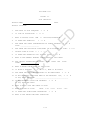
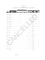
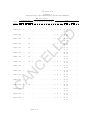
FIGURE 1-1
SITE CHECKLIST
PROJECT NAME:
DATE:
PROJECT LOCATION:
1.
ARE ROADS TO SITE ADEQUATE?
2.
IS SITE IN FLOODPLAIN?
3.
WHAT IS PROJECT TYPE?
4.
IS THERE ANY ASBESTOS?
5.
ARE THERE ANY OTHER CONTAMINATION OR SAFETY HAZARDS?
TYPE: _____________________
6.
ARE THERE ANY HISTORICAL STRUCTURES ON OR ADJACENT TO SITE?
7.
SEISMIC ZONE OF SITE?
8.
IS THERE ANY EXPANSIVE SOIL AT THIS SITE?
9.
WHAT IS THE GENERAL BEARING STRATA DEPTH IN THIS AREA?
or
NEW
N
N
or
ADDITION/ALTERATION
or
N
EL
L
Y
0
or
ED
Y
Y
1
2
3
C
10. ARE SPECIAL FOUNDATIONS REQUIRED?
OTHER: ____________________
Y
or
N
Y or N
4
NONE
Y
or
PIERS
N
MAT
PILES
11. WHAT IS WATER TABLE LEVEL AT THIS SITE?
Y
or
N
IF Y, WHAT IS NC-LEVEL?
AN
12. IS NOISE A PROBLEM?
13. ARE THERE ANY EXISTING STRUCTURES TO BE DEMOLISHED?
Y
or
14. DO ANY DISPLACED FUNCTIONS NEED TO BE REPLACED? N/A, Y or
IF YES, WHAT ARE THEY? _____________________________________
15. DO ANY EASEMENTS CROSS THE PROPERTY?
IF YES, WHAT ARE THEY?
Y
or
N
C
16. WHAT IS BASIC SIZE AND SHAPE OF SITE?
17. WHAT IS SLOPE OF SITE?
LEVEL
3-8%
18. IS THERE ANY SIGNIFICANT VEGETATION?
19. WHAT IS THE PREVAILING WIND DIRECTION?
1-14
9-15%
Y
or
16-25%
N
>25%
N
N
MIL-HDBK-1191
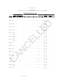
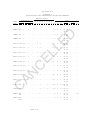
FIGURE 1-1 (CONTINUED)
20. WHAT IS AVERAGE ANNUAL RAINFALL?
INCHES
21. WHAT IS AVERAGE ANNUAL SNOWFALL?
INCHES
22. WHAT ARE THE CLIMATIC CONDITIONS?
WIN DB
23. DOES WATER SUPPLY NEED TO BE TREATED?
Y
SUM DB
or
WB
N
DISTANCE TO
CONNECTION POINT
SYSTEM
WATER
FEET
FIRE WATER
FEET
___________ FEET
PSI
#/HR
PSI
FEET
GPM
TEMP
FEET
GPM
TEMP
FEET
GPM
FEET
GPM
FEET
GPM
CFM
FEET
KVA
KILOVOLT
___________ FEET
_____KVA
_____KILOVOLT
SANITARY SEWER
AN
C
STORM SEWER
ELECTRICAL-Alternate
FIBER OPTIC LINE
_____GPM
FEET
CHILLED WATER
CABLE TV
PSI
PSI
HI-TEMP HOT WATER
ELECTRICAL-Primary
GPM
#/HR
UNTREATED STEAM
GAS
CAPACITY AVAILABLE
TO SITE
EL
L
CLEAN STEAM
ED
24. WHAT IS THE AVAILABILITY OF UTILITIES TO THE SITE?
FEET
___________ FEET
FEET
SWITCH CAPACITY
PATH. WASTE
FEET
#/DAY
C
COMMUNICATIONS
25.
WHAT IS THE FREQUENCY OF LIGHTNING?
26. Is the site coordinated with the installation and tied into the
installation Master Plan?
27. Has the history of the site been researched and investigated at
least fifty years prior?
28.
ADDITIONAL REMARKS: (Add additional pages if necessary):
1-15
MIL-HDBK-1191
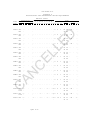
CERTIFICATION OFFICIAL:
NAME:
TITLE:
ORGANIZATION:
C
AN
C
EL
L
ED
SIGNATURE:
1-16
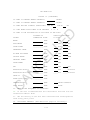
MIL-HDBK-1191
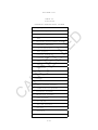
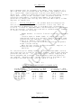
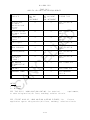
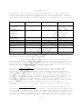
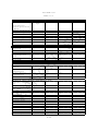
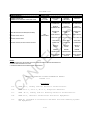
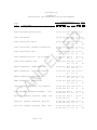
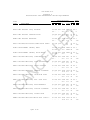
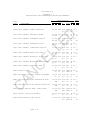
FIGURE 1-2
LOGISTICAL RESPONSIBILITY FOR BUILDING SYSTEMS
Special Instructions. The items listed in this section shall be included
in construction cost estimates as appropriate.
Logistical Responsibility(1)
ED
ITEM
-----------------------------------BUILDING AND GROUNDS
C
ELECTRICAL SERVICE
EL
L
Hospital buildings (including administration)
Medical Clinic buildings
Dental Clinic buildings
Clinical and Medical Research Laboratory buildings
Animal holding buildings
Maintenance shop buildings
Garages and automotive shelters
Power plant buildings (steam and/or electrical)
Sewage disposal plant structures
Medical helicopter/air evac landing pads
Chapel
Recreational building (including Red Cross,
gymnasiums and swimming pools)
Recreational fields (including tennis courts,
baseball diamonds, etc.)
Guard and sentry boxes, gate houses
Incinerator buildings
AN
Wiring (including material)
Conduits
Switches, panels boxes, service outlets
Transformers (step-down and distribution)
Lighting, fixtures (including initial lamping)
Generating equipment (including emergency)
Explosion-proof fixtures
Power conditioning/surge protectors
A
A
A
A
A
A
A
A
A
A
A
A
A
A
A
A
A
A
A
A
A
A
A
HEATING, AIR CONDITIONING, AND VENTILATION
C
Air conditioning (including packaged units)
Boiler plants and water heaters
Heat and steam distribution systems
Central vacuum cleaning system
(1)
See Para 16.2.1 for definition.
1-17
A
A
A
A
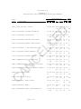
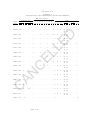
MIL-HDBK-1191
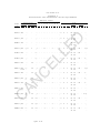
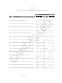
Logistical Responsibility(1)
Piping valves, fittings, and outlets
Toilet, bath, and lavatory fixtures (including
shower stalls, mirrors, towel racks, toilet
paper dispensers, paper towel dispensers,
soap dispensers, and bed pan washers
Sewer systems and plants
Gas, air pressure and suction, and medical
gas systems
Automatic sprinkler systems
Fire protection system (water)
REFRIGERATION
A
A
EL
L
Refrigeration (walk-in)
Deep freeze (walk-in)
Built-in morgue refrigerators
A
COMMUNICATIONS:
A
A
A
ED
ITEM
-----------------------------------PLUMBING
A
A
A
A
C
Telephone System, Complete:
Interior Conduits, Boxes, Outlets, Wiring
Instruments, Outside cable and support work
Interior Telephone Switching Equipment
Supporting Expansion Work at Main Exchange
A
A
A
A
Intercom systems, Complete:
Conduits, Boxes, Wiring, and Equipment
A
Public Address System, Complete:
Conduits, Boxes, Wiring, and Equipment
A
Television System:
Entertainment:
Conduits, Boxes, Wiring, Antennas
Head Ends and Distribution Equipment
Mounting Brackets and Low Voltage Supplies
Television Receivers
A
A
A
C
C
AN
C
LAN - Local Area Network:
Conduit, Boxes, Wiring, Patch panels, outlets
LAN Equipment
Training:
Conduits, Boxes, Wiring, Distribution Eq.
Cameras, Monitors, Control Equipment
A
C
Security:
Conduits, Boxes, Blank Outlets
Cameras, Monitors, Wiring
Control Equipment
A
C
C
1-18
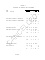
MIL-HDBK-1191
ITEM
------------------------------------
Logistical Responsibility(1)
COMMUNICATIONS - (Continued)
A
C
Staff Radio Paging Systems, Complete:
Conduits, Boxes, Wiring, Equipment
A
Other Radio Systems, i.e., EMS, etc.:
Conduits, Boxes, Site Support Work
Antennas, Equipment, and Wiring
Card Access System, Complete:
Conduits, Boxes, Wiring, Equipment
EL
L
Nurses' Call Systems, Complete:
Conduits, Boxes, Wiring, Equipment
ED
Patient Physiological Monitoring:
Conduits, Boxes, Blank Outlets
Equipment
A
C
A
A
A
C
Intrusion detection System:
Conduits, Boxes, Blank Outlets
Wiring, Sensors and Control Equipment
A
A
Fire Detection and Alarm System, Complete
A
Clock Systems:Central Clock System, Complete
Battery Clocks
A
C
TRANSPORTATION SYSTEM
A
SIGNAGE (INTERNAL/EXTERNAL)
A
C
AN
C
Central Dictating System:
Conduits, Boxes, Wiring, Outlets
Dictation Equipment
1-19
MIL-HDBK-1191
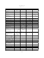
FIGURE 1-3
CHECKLIST FOR MEDICAL FACILITY UPGRADE SURVEYS
(Select one "Type of Survey" and any "Special Studies" required)
A.
NO
1. BASIC LIFE SAFETY SURVEY.
with the following standards:
Survey will address compliance
ED
YES
TYPES OF SURVEY.
a. NFPA 101, Chapter 13, "Existing Health Care
Occupancies". Use exception allowed in NFPA 101, para. 71.2, so that the survey will not evaluate general compliance
with referenced NFPA standards.
YES
NO
EL
L
b. NFPA 99, Chapter 3, "Electrical Systems" as it
relates to Essential Electrical System - Life Safety Branch
only.
2. LIFE SAFETY AND UTILITY SYSTEMS SURVEY. Survey will
address compliance with the following standards:
a. NFPA 101, Chapter 13, "Existing Health Care
Occupancies" including general compliance with referenced
standards per NFPA 101, paragraph 7-1.2.
Electrical systems.
Communication and signal systems.
HVAC.
Plumbing.
Medical gas systems.
Transportation and material handling systems.
Other. Provide list.
________________________
________________________
________________________
AN
NO
NO
NO
NO
NO
NO
NO
C
YES
YES
YES
YES
YES
YES
YES
C
b. The building utility systems will be surveyed in relation
to: MIL-HDBK-1191, "DoD Medical and Dental Treatment
Facilities Design and Construction Criteria"; and Military
Department Criteria. The following systems will be
addressed:
YES
NO
3. FACILITY MODERNIZATION SURVEY. Survey will address
compliance with the following standards:
a. NFPA 101, Chapter 13, "Existing Health Care
Occupancies" including general compliance with referenced
standards per NFPA 101, paragraph 7-1.2.
1-20
MIL-HDBK-1191
CHECKLIST FOR MEDICAL FACILITY UPGRADE SURVEYS
(Select one "Type of Survey" and any "Special Studies" required)
b. The building will be surveyed in relation to: MILHDBK-1191, and Military Department Criteria. The following
systems will be addressed:
ED
SPECIAL STUDIES.
NO
NO
NO
Economic Analysis. (Attach scope of analysis).
Seismic/structural evaluation.
Hazardous/Toxic substance survey.
____ Asbestos survey
____ PCB survey
____ Lead survey (in paint or in potable water)
____ Mercury contamination
____ Underground Fuel Tank Survey.
____ Other. Provide list, _____________________.
Maintenance and Repair Deficiency survey.
Uniform Federal Accessibility Standard and Americans with
Disabilities Act Guidelines Compliance.
Other. Provide list.______________________.
AN
YES
YES
YES
C
B.
NO Site and Parking issues.
NO Utility services.
NO Structure.
NO Exterior Finishes, roofing, glazing, etc.
NO Medical/Functional Requirements.
NO Architectural finishes.
NO Equipment and Furnishings
NO Waste Management System.
NO Transportation and material handling systems.
NO Electrical systems.
NO Communication and signal systems.
NO Energy Usage/System Efficiency Survey.
NO HVAC.
NO Plumbing.
NO Medical gas systems.
NO Other. Provide list.
________________________
________________________
________________________
EL
L
YES
YES
YES
YES
YES
YES
YES
YES
YES
YES
YES
YES
YES
YES
YES
YES
NO
NO
YES
NO
C
YES
YES
1-21
MIL-HDBK-1191
SECTION 2:
DESIGN PROCEDURES, SUBMITTALS, AND DOCUMENTATION
2.1 General. This section defines the minimum OASD-HA (TMA/DMFO)
requirements for design procedures, submittals, and documentation for a
typical DoD Medical MILCON project. The Design Agent(s), in coordination
with the using Military Service(s), may establish additional or lesser
project specific requirements to meet specific project requirements.
Submittal requirement variations for TMA/DMFO submissions must have written
TMA/DMFO approval.
2.2 Design Goals.
ED
2.2.1 Scope and Criteria. The goal during concept design (0 to 35%)
development is to produce concept design documentation which meets project
requirements and complies with criteria while establishing final project
scope and an appropriate Programmed Amount (PA). Final scope and PA will be
based on the approved concept submittal and validated cost estimate.
2.2.3 Design Schedules.
EL
L
2.2.2 Design to Cost. The goal during the final design phase (35 to 100%
design completion) is to produce a set of construction documents within the
PA and/or DDA established at the concept design approval. If design
requirements or refinements cause the estimated project cost to exceed the
established PA, the Design Agent with participation of the using Military
Department, will present cost adjustment or reduction alternatives to
TMA/DMFO before completing the design documents.
C
2.2.3.1
Major Construction. For specified location projects, the
TMA/DMFO goal is to be at concept (35%) design by 1 August of the year prior
to planned budget execution. The Design Agent must request written approval
from TMA/DMFO for late submission. The goal during final design is to
complete design in time for a construction contract award during the first
quarter of the program year of the project.
2.3
AN
2.2.3.2
Unspecified Minor Construction. For Unspecified Minor
Construction (DODI 4270.36, reference 2a), the TMA/DMFO goal is to have
designs complete and projects ready for advertisement within 12 months of
the date of the original TMA/DMFO Design Authorization Memorandum.
Design Sequence and Responsibilities.
C
2.3.1
2807 Action. TMA/RM issues the Section 2807, Title 10 USC
(reference 2b) Congressional notification. Typically, the 2807 notification
is conducted concurrently with the Design Authorization to select an
Architect/Engineer. This notification is required for all projects where the
funded cost of design is expected to exceed $500,000 (typically a projected
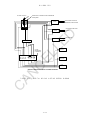
construction cost of $3.5 million and up). (See Figure 2-1).
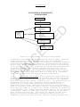
2.3.2
Design Funds. TMA/RMFO sub-allocates design funds to the
Design Agents to achieve the authorized level of design in accordance with
Figure 2-1.
2.3.3
Design Authorization. The TMA/DMFO issues the design
authorizations to the Design Agent with an information copy to the using
Military Department, as appropriate, to meet design and programming
2-1
MIL-HDBK-1191
milestones in Figure 2-1. The Design Agent manages design in accordance
with established policies and procedures unless otherwise established in
coordination with the user and TMA/DMFO during initial project acquisition
strategy planning. Separate design authorization memoranda are normally
issued for A-E Selection, Concept Design, and Final Design. However,
separate or combined DA’s may be issued for design-build projects. The
Design Agents shall not pursue any level of design beyond that authorized in
writing by TMA/RM.
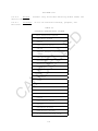
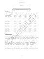
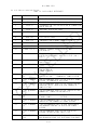
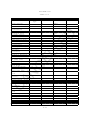
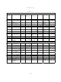
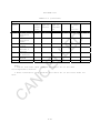
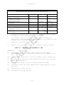
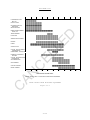
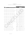
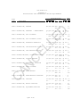
Figure 2-1
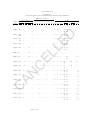
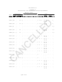
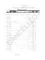
ED
DoD MEDICAL MILITARY CONSTRUCTION TIMETABLE
FOR PLANNING, BUDGETING, AND EXECUTION
OF A “TYPICAL” MILCON” PROJECT IN THE FY XX PROGRAM
FY 02
FY 03
FY 04
FEB 98
JUL 98
APR 99
FEB 99
JUL 99
APR 00
FEB 00
JUL 00
APR 01
MAY 99
MAY 00
MAY 01
· Issue 35% Design Authorization (TMA)
OCT 99
OCT 00
OCT 01
· Best Concept Design Cost Estimate to TMA (Design Agent)
JUL 00
JUL 01
JUL 02
C
ACTIVITY
EL
L
THIS IS A MINIMUM TIMETABLE WHICH DOES NOT PRECLUDE EARLIER
DESIGN STARTS FOR OCONUS, LARGE, OR COMPLEX PROJECTS OR TO MEET ALTERNATIVE
EXECUTION STRATEGIES (E.G., DESIGN-BUILD, etc) DEVELOPED JOINTLY BY TMA, THE
AGENT, AND THE SERVICE--CRITICAL MILESTONES ARE IN BOLDFACE
· 35% Design Submission to TMA (Design Agent)
AUG 00
JUL 01
JUL02
· Scope and PA Approval and 35% Design Certified (TMA)
SEP 00
AUG 01
AUG 02
· FYXX Budget Submitted to OSD(Comp) (TMA)
SEP 00
SEP 01
SEP 02
· Issue Final Design Authorization (TMA)
OCT 00
OCT 01
OCT 02
· FYXX MILCON Program to Congress (DOD)
JAN 01
JAN 02
JAN 03
· Ready to Advertise (Design Agent)
SEP 01
SEP02
SEP03
· FYXX Funds Available (TMA)
Nov 01
· Begin FYXX Planning Year
· Begin FYXX EA Efforts (Services)
· FYXX EA Efforts Completed (Services) and Validated (DMFO)
C
· Preliminary Scope Available (Services)
AN
· Determine Execution Strategy (Services/Design Agent/DMFO)
. Submit Project Book to TMA
. Final PFD and DD Form 1391 validated by TMA
· Release Design Authorization (TMA)
· 2807 Action (TMA)
2-2
NOV 02 NOV 03
MIL-HDBK-1191
2.3.3.1
Exceptions. Some larger, more complex, or OCONUS projects may
require a greater level of effort and more time to achieve the concept (35%)
design milestone in Figure 2-1. When this occurs, the Design Agent, in
coordination with the using military department, may request variations to
the milestones in Figure 2-1 from TMA/DMFO.
ED
2.3.4
Architect-Engineer (A-E) Selection Authorization. This is
authorization to synopsize, slate, select an A-E and to negotiate, but not
to award a contract, or proceed with design. Following authorization by
TMA/RM, the Design Agent selects an A-E following their established
procedures. The using Military Department may participate in A-E selection
in accordance with established Memoranda of Understanding (MOUs). TMA/DMFO
may also participate when so specified in the design authorization or when
requested by the using Service and/or the Design Agent.
EL
L
2.3.5
Concepts (0 to 35%) Design Authorization. This is
authorization to award an A-E contract and to proceed to the concept (35%)
level of design. This authorization will normally be issued when a project
has a completed economic analysis, an approved Program For Design (PFD), the
project is in the appropriate Program FY to start design action, and design
funds are available. Normal presentation requirements to the TMA/DMFO are
the S2 (preliminary concept design) for scope approval and the S4 (final
concept/35% design)for cost approval. The Concept Design phase is complete
when TMA/DMFO approves the S4 submittal, scope and cost estimate.
C
2.3.6
Concept (35%) Review and Certification. Following design agent
presentation and certification of the concept submittal, TMA/DMFO certifies
35 percent design completion and project cost estimates by 15 September of
the year prior to planned budget execution. The TMA/DMFO will also notify
the Design Agent and the using Military Department if the Concept Design is
approved, with or without comments, or disapproved, with comments.
AN
2.3.7
Final Design Authorization. This is authorization to proceed
from concept (35%) to final design. TMA/RM normally provides this
authorization after the concept design is certified complete by the Design
Agent and approved by the TMA/DMFO.
2.3.8
Design Coordination. Designs will be developed and managed
with close coordination between the Design Agent, using Military Department
representatives, and TMA/DMFO. TMA/DMFO will be advised of issues relating
to scope, design or construction cost, criteria, policy and procedure,
and/or schedule.
C
2.3.9
Design Changes. The Design Agent, in coordination with the
using Military Department, will submit proposed concept design scope
refinements and final design scope changes to TMA/DMFO for approval. After
S2 approval by TMA/DMFO, all scope increases above the TMA/RM authorized
amount will be submitted to TMA/DMFO for approval with the S4 presentation.
After the concept design approval by TMA/DMFO, all scope increases in area
and/or cost, or which add new functions will be submitted to TMA/DMFO for
approval with justification prior to incorporation into the design. The
Design Agent may decide whether or not design should be suspended pending
TMA/DMFO action. Design changes which jeopardize the Design Agent's ability
to meet the required design schedule will be avoided, unless necessary to
meet criteria or mission requirements.
2-3
MIL-HDBK-1191
2.3.10
Stopped or Deferred Designs. Decisions to stop or defer designs
will be made by TMA/DMFO, in coordination with the design agent and the
using Service. Written direction will be provided to the Design Agent and
the using Service.
2.4
Reporting Requirements. The Design Agents will establish design
cost targets, maintain accurate records on design fees, schedules,
construction cost, and other project data and report this information as
required below.
ED
2.4.1
Notification of Concept Design Start. The Design Agent will
notify TMA/DMFO and using military department of the A-E's name, and the
design schedule within seven calendar days after the A-E has been issued a
Notice-To-Proceed (NTP) to concept (35%) design.
2.4.2
Notification of Final Design Start. The Design Agent will
notify TMA/DMFO of the schedule for the Final Design within seven (7)
calendar days after the A-E has been issued a NTP to design completion.
EL
L
2.4.3
Quarterly Execution Reports. The Design Agent shall submit the
following reports to TMA/DMFO and using Military Department Agencies no
later than three working days prior to each Quarterly Execution meeting.
Automated reports currently in use by the Design and Construction Agents
which contain the requested information are acceptable substitutes for the
report formats listed below: (Fig 2-3)
2.4.3.1
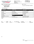
Design Funds Status Report. Provide in format of Figure 2-2
for all projects authorized for design by TMA/RM.
C
2.4.3.2
Project Status Report. Provide in format of Figure 2-3 for each
project authorized for design by TMA/RM.
2.4.3.3
MILCON Funds Status Report.
format for all appropriated projects.
Provide a report in Figure 2-4
C
AN
2.5
Design-Build Projects. For the vast majority of projects, the
traditional facilities acquisition method of firm-fixed-price design-bid-build
will continue to be used. However, other non-traditional project delivery
systems, to include design-build and third party contracting, should be
considered when appropriate. With the concurrence of the Using Military
Department, the Design Agents may elect to procure medical facilities using
the Design-Build process. The Request For Proposal (RFP) for a medical
facility shall include a sufficient design developed to the concept level to
effectively establish scope and cost. The Design Agent, in consultation
with the Using Military Department, shall determine for each project whether
specifications shall be prescriptive, performance, or a combination thereof.
2.6 Design Submittals and Documentation Requirements.
2.6.1
Economic, Architectural, Engineering, and Environmental
Studies. The design is to be supported by architectural, engineering,
economic, and environmental evaluations of those features, which contribute
most to the construction cost, energy efficiency, and environmental impact.
The design is to provide the optimum combination for an efficient and
2-4
MIL-HDBK-1191
effective facility at the most economical cost with the least adverse
environmental impact. Such studies shall consider life-cycle-cost of the
facility, and not just the initial construction cost. Specific information
concerning study requirements will be provided in accordance with
appropriate laws and Executive Orders as defined by the Design Agent(s).
Economic Analyses (EA) of new versus addition/alteration will be paid for
and accomplished by the appropriate Military Department with their operation
and maintenance funds for projects with a program amount of $2.0 million and
over prior to any design authorization being issued.
ED
2.6.2 Value Engineering Study (VE). The Design/Construction Agent will
establish procedures for conducting VE studies in accordance with Office of
Management and Budget Circular No. A-131 and Section 432, Title 41, USC,
Value Engineering. VE studies consist of investigations of certain highcost aspects of a design to determine if an alternate way exists to achieve
an improved design, which meets all functional requirements, at a lower
life—cycle-cost.
EL
L
2.6.3 Design Documentation. The Design Agent, in coordination with the
using military department, is responsible for the design documentation on
each project. The Contract A-E will be held fully accountable for design in
accordance with the "Responsibility of the Architect-Engineer Contractor"
clause set out in FAR 52.236-23. However, Design Agents shall provide for
peer review of appropriate portions of design documents to assure the proper
functioning of the Architect-Engineer’s own Quality Control effort.
2.6.3.1 Submissions required for TMA/DMFO. The design documentation for
Schematic and Concept level design, described in B.2 and B.4 of Appendix B
will be submitted to TMA/DMFO for approval.
AN
C
2.6.3.2 Appendix B. Appendix B provides a description of general submittal
and documentation requirements, which are appropriate for a typical medical
facility. For minor facilities, such as medical warehouses, contingency
facilities, or small outpatient clinics, Design Agents may deviate from
these submission requirements as practically and economically appropriate
for the scope and complexity of the project.
C
2.6.4 Schematic Design Submittal (S2). This submittal includes development
of the room-by-room floor plans, elevations, and initial analysis of the
building systems. The primary purpose of this submittal and review is to
identify and resolve all major space program deficiencies at an early stage
in design and "fix" the footprint of the building. The Design Agent and
using Military Department representatives, if required based on the project
acquisition plan, will present the reviewed S2 to TMA/DMFO. Requests for
scope revisions with justification should be submitted at this time. Scope
changes will not be entertained after approval of S2 unless fully justified.
TMA/DMFO will provide approval/disapproval, with review comments, within 14
calendar days of the submittal.
2.6.5
Concept (35 Percent) Design Submittal (S4). This is the
technical Concept Design submittal. The design agent will certify to
TMA/DMFO that design is 35 percent complete. The Design Agent, with using
Military Department coordination and participation, will submit a summary of
the reviewed S-4 to TMA/DMFO. Final scope and PA (cost) shall be determined
with this submission.
All issues regarding costs, Value Engineering Study
(VE), constructability, phasing, and any other special studies must be
2-5
MIL-HDBK-1191
resolved, though the results of all studies may not be incorporated prior to
presenting this submission to TMA/DMFO for approval.
2.7
Rendering. If the design agent requires a rendering, then a
photographic copy of the rendering shall be provided to TMA/DMFO and the
military department. The rendering should be prepared either before or after
the concept submittal is approved by TMA/DMFO. The TMA/DMFO copy of the
rendering should be titled, matted, glazed with nonglare glass or plexiglass
and framed in brushed aluminum or other format prescribed by the Design
Agent.
EL
L
ED
2.8
Design Review Policy. Prior to use of a design documents package for
construction, the Design Agent shall conduct an independent review to evaluate
the completeness and quality of the documents.
This review does not replace or
nullify the designer's own quality control process or review responsibilities.
The A-E will be held fully accountable for design in accordance with the
"Responsibility of the Architect-Engineer Contractor" clause set out in FAR
52.236-23. The Design Agent’s review is to establish that the designer has
fulfilled the documentation requirements of his contract, adequately addressed
any unique government requirements, and provided documents exhibiting a level
of accuracy, coordination, completeness, clarity, and absence of error
indicative of a quality design and an effective designer quality control
procedure. In addition, A-E design shall be accomplished or reviewed and
approved by architects, engineers or other professionals registered to practice
in the particular professional field in accordance with FAR 52.236-25.
AN
C
2.8.1
Review Agency Qualifications. Designs prepared by private A-E
firms or geographical elements of the Design Agent will be reviewed by the
Design Agent’s Medical Facilities Design Office (Center of Expertise for COE),
employing a highly qualified, multi-disciplinary team of engineer and
architect professionals with extensive experience, and day-to-day involvement
in, medical facility designs and technical issues. The Design Agent’s Medical
Facilities Design Office or Center of Expertise shall review all medically
unique aspects of the design, and all aspects of design shown to be historical
areas of concern for medical facilities. Design Agents may designate
qualified engineer and architect professionals without extensive experience in
the medical field to review general aspects of medical facility designs.
C
2.8.2
Constructability Review. The Design Agent shall provide for an
independent Constructability Review for all medical facility projects.
Constructability is defined as the ease with which a designated project can
be administered, bid, built, enforced, and understood. Constructability
must be strongly emphasized by the designer, and Design Agent, throughout
the entire planning and design process. As a minimum, these reviews should
occur at both the 35% and Final Design completion stages.
2.9
Design Management Plan. For each project, the Design Agent shall
develop a plan for managing the design of the facility.
This plan shall
identify project schedule and milestones.
2.10
Construction Cost Estimates. Preparation, review, and approval
of construction cost estimates shall be in accordance with established design
agent practices. All estimates prepared by A-E firms will be reviewed and
validated by the cost engineering element of the design agent. Prior to the
submittal to TMA/DMFO, estimates prepared by in-house personnel will be
reviewed in accordance with established procedures. The quality and integrity
2-6
MIL-HDBK-1191
of cost estimates will not be compromised in order to meet completion
deadlines or imposed budget requirements.
2.11
Final Design (35 percent to 100 percent). The final design phase
may be initiated only after approval of Concept Design by the TMA/DMFO. If,
in the preparation of final design, it is necessary to deviate substantially
from the approved Concept Design, such as the rearrangement of a major
medical department or a change in the interrelationship of functional
elements, design may be suspended and the pertinent facts and justifications
concerning the deviations will be submitted for review and approval by
TMA/DMFO.
ED
2.12
Comprehensive Interior Design (CID). The final design phase, at
option of the using Military Department, may include a CID effort (using
MILCON P&D funds) for furniture and accessory selection, layout and
identification, and documentation for procurement. Subsequent selections of
furnishings and medical equipment are to be coordinated with the CID.
EL
L
2.13
Final Submittal to TMA/DMFO . When the design is complete, the
Design Agent will submit a copy of the final documents (i.e. CD-ROM,
drawings, specification, cost estimate, instructions to bidders, etc.) to
TMA/DMFO. Along with this package, the Design Agent shall provide a
memorandum to TMA/DMFO certifying that the design has been completed and
that all technical requirements and cost criteria approved at the 35 Percent
Design stage have been incorporated into the Final Design.
REFERENCES
DoD Directive 4270.36, "DoD Emergency, Contingency and Other
Unprogrammed Construction Projects." May 17,1997
2b.
Section 2807, Title 10 USC, "Architectural and Engineering
Services and Construction Design."
2c.
DOD Directive 6015.1&, "Department of Defense Policies for
Planning and Execution of Military Healthcare Facilities."
(DRAFT)
AN
DoD Directive 4245.8, "Value Engineering."
C
2d.
C
2a.
2-7
MIL-HDBK-1191
FIGURE 2-2
DESIGN FUNDS STATUS REPORT
EST
0-35%
COST
EST
35-100%
COST
TOTAL
DESIGN
COST
DESIGN
FUNDS
AVAIL
DELTA
C
AN
C
EL
L
ED
PROJECT
ACT
DES
%
2-8
MIL-HDBK-1191
FIGURE 2-3
PROJECT STATUS REPORT
PROJECT: FY:
Major/Minor/BRAC
NUMBER: _____ USING SERVICE:_____ LOCATION: _________
_____________
TITLE:
Programmed Amount (PA):
DESIGN
CONSTRUCTION
DDA:
AWARD CWE:
CWE:
CURRENT CWE:
STATUS: TMA/DMFO
AUTH:
LEVEL OF
DESIGN (%):
2807 NOTIFICATION
A-E SELECT AUTHORITY
A/E SELECTION COMPLETE
C
DEFTAB SUBMIT TO TMA/DMFO
DEFTAB APPROVED BY TMA/DMFO
ACTUAL
DATE
AN
A-E SUBMITS S-1
A-E SUBMITS S-2
S-2 SUBMITTED TO TMA/DMFO
TMA/DMFO S-2 REVIEW COMPLETE
A-E SUBMITS S-3
A-E SUBMITS S-4
35% SUBMITTED TO TMA/DMFO
35% APPROVED BY TMA/DMFO
AUTHORITY
65%
100%
FINALS
C
100% DESIGN
A-E SUBMITS
A-E SUBMITS
A-E SUBMITS
CONSTRUCTION
COMPLETE (%): SCH.
ACT.______
EL
L
SCHEDULE
DATE
EVENT
35% DESIGN AUTHORITY
AWARD A/E CONTRACT
CONTINGENCY
STARTING TOTAL:
CHANGES TO DATE:
PENDING CHANGES:
REMAINING BALANCES:
ED
FUNDS:
REQUEST ADVERTISE AUTH.
ADVERTISE AUTHORITY
BID OPENING
AWARD AUTHORITY
CONST. CONTRACT AWARD
CONST. COMPLETED
BENEFICIAL OCCUPANCY
FACILITY OPERATIONAL
2-9
REMARKS
MIL-HDBK-1191
C
AN
C
EL
L
ED
ISSUES:
2-10
MIL-HDBK-1191
FIGURE 2-4
MILCON FUNDS STATUS REPORT
SUBALLOCATED
FUNDS
EST
EST BID
CWE DATE
ACT
CWE
ACT
AWARD
DATE
%CONST COMP
SCH
ACT
C
AN
C
EL
L
ED
USING
PROJECT TITLE/ MIL
LOCATION
DEPT
PA
2-11
MIL-HDBK-1191
FIGURE 2-5
Instructions for Preparing Gross Area Tabulation.
This is the square meter (foot) quantity number used on the
project DD Form 1391. The gross area documentation consists of
calculation and tabulation of the building gross floor area
illustrated with small scale, single-line dimensioned drawings as
demonstrated in the attached figure. The following procedures will be
used to calculate the gross building area.
ED
a. The gross area includes the total area of all floors with a
floor-to-ceiling height of 2134 mm (7 ft) or greater, including
basements, mezzanines, penthouses, mechanical and electrical spaces,
enclosed loading docks, and ambulance garages. Gross area is measured
from the exterior surfaces of all enclosing walls except where the
exterior wall surface overhangs the exterior window surface by one
foot or more. In this case, the gross area is measured from a point
one-half the distance between the exterior plane of the window glazing
and the outermost plane of the wall.
(1)
(2)
(3)
EL
L
b. The following spaces are counted as one-half of the actual
gross area:
Exterior balconies and porches.
Covered but not enclosed walks, passageways, ramps,
ambulance shelters, and entry canopies.
Exterior open stairs (covered or uncovered).
C
c. The following shaft type elements are counted in the gross
area of one floor only: atria, unenclosed floor openings, stairs,
escalators, elevators and lifts, mechanical and electrical shafts, and
other shafts connecting two or more floors.
AN
d. The following areas are not counted in the gross area: spaces
with less than seven feet floor-to-ceiling height; exterior insulation
applied to an existing building; exterior, uncovered, unenclosed
terraces, ramps, stoops, and pads; open courtyards; utility tunnels;
equipment yards; and crawl spaces. Crawl spaces with a clear height
of seven feet or greater are not counted in the gross area provided
the clear height of seven feet and greater is the result of the
natural site terrain or foundation construction.
C
e. The gross area for site and supporting facilities, such as the
central utility plant, pump house, and utility buildings, which are
not included in the Program For Design is tabulated separately from
the main building gross area tabulation. The gross area of all site
and supporting facilities which are identified in the Program for
Design is accounted for in the main building gross area tabulation.
f. A separate tabulation is required for the mechanical area.
This tabulation will include the net area of all mechanical,
electrical, and telecommunication rooms and utility shafts. Walls,
partitions and structural elements associated with these spaces are
included in the general gross area not the mechanical area. Vertical
circulation spaces, such as elevators, escalators, lifts, stairs, and
trash chutes, are counted in the general gross area not the mechanical
2-12
MIL-HDBK-1191
C
AN
C
EL
L
ED
area. Mechanical, plumbing, electrical, and telecommunication shafts
are counted in the mechanical area.
2-13
EL
L
ED
MIL-HDBK-1191
GROSS AREA TAKE-OFF
C
AN
C
Plan Area
Plan
Reference/Type
Dimensions
A bldg. space 29300 x 37200
B
"
7300 x 7300
C
"
25300 x 34800
D
"
7300 x 18300
E
"
8500 x 14600
F
"
7300 x 11000
G
"
36300 x 38000
H
"
3000 x 12200
I
"
7600 x 16500
K
"
1500 x 2100
L
"
700 x 6100
M entry canopy 1800 x 2700x2
N covered walk 2100 x 45100
O
"
2100 x 7000
P
"
2100 x 3700
Q covered porch 2700 x 3000
R covered walk 2700 x 12200
S covered porch 1200 x 2400
deduct
T alcove deduct 1700 x 1800x3
U courtyard
6100 x 8500
deduct
V alcove deduct 1200 x 2400
W
"
1200 x 1800x4
x
x
x
x
x
x
x
x
x
x
x
x
x
x
x
x
x
x
Scope
1.0
1.0
1.0
1.0
1.0
1.0
1.0
1.0
1.0
1.0
1.0
.5
.5
.5
.5
.5
.5
-.5
x
x
-1.0
-1.0
-9.18
-51.85
x
x
-1.0
-1.0
-2.88
-8.64
First Floor Total Gross Area
GSM
1089.96
53.29
880.44
133.59
124.10
80.30
1379.40
36.60
125.40
3.15
4.27
4.86
47.35
7.35
3.88
4.05
16.47
-1.44
3920.47
FIGURE 2-5
2-14
MIL-HDBK-1191
FIGURE 2-6
NET AREA TABULATION
The net floor area of a space is measured from the interior surface of
the walls that enclose the space. Exterior walls, interior
partitions, columns, structural members, and internal circulation
space for other than individual occupancy(ies) are excluded from the
net floor area.
AN
C
EL
L
ED
Provide a tabulation of net areas, by room, in thirteen columns as
follows:
a) Room Code Number From Program For Design (PFD),
b) Functional title of room,
c) Number of rooms,
d) Net area of room from Program For Design,
e) Total net space programmed for rooms [Product of cols.(c) x
(d)],
f) If Add/Alt - allocated to unaltered existing space,
g) If Add/Alt - allocated to altered existing space,
h) If Add/Alt - allocated to new space,
i) Net individual room areas as designed,
j) Difference between program and design [columns (i) minus
(d)],
k) Percent variation between program and design [cols
(j)/(d)x100%],
l) Notes. Provide justification if the deviation listed in k)
is
more than 10 percent. Rooms of 4.65 m2 (50 ft2) or less are
exempt from the 10 percent justification process. The
justification is to indicate why the deviation was made, not
just who authorized it. As a minimum, the spaces considered
irreducible are Operating Rooms, Examination Rooms, Treatment
Rooms, Provider's Offices, Emergency Rooms, Dental Treatment
Rooms, Labor Rooms, Delivery Rooms, Diagnostic and Therapeutic
Radiology Rooms, and Patient Bedrooms/Toilets. Depending on
function and mission, there may be other rooms identified by the
using Military Department which will be identified as
irreducible, and,
m) Provide a total summary of each column.
C
After the above is accomplished, prepare a Net to Gross ratio in the
same format as provided in the Program For Design (PFD).
2-15
MIL-HDBK-1191
FIGURE 2-6 (continued)
NET TO GROSS SQUARE METER (GSM)1 CALCULATIONS
FACILITY W/O HARDENING
NEW/REPLACEMENT PROJECT
ALLOWANCES/CATEGORIES
AMBULATORY
HEALTH CARE
FACILITIES
STATION/
COMMUNITY
HOSPITALS
_________________________________________________________
TOTAL NSM2
NSM
NSM
NSM
11.0% of NSM
13.0% of NSM
14.0% of NSM
CIRCULATION
of NSM
41.0% of NSM
41.5% of NSM
42.0% of NSM
14.0% of NSM
HALF AREAS
1.5% of NSM
FLEXIBILITY
1.0% of NSM
TOTAL GSM
168.5% of NSM
NSM
16.0% of NSM
46.0%
15.0% of NSM
15.5% of NSM
15.5% of NSM
1.5% of NSM
1.5% of NSM
1.5% of NSM
1.0% of NSM
1.0% of NSM
1.0% of NSM
172.0% of NSM
174.0% of NSM
180.0% of NSM
C
NOTES:
EL
L
MECHANICAL
WALLS &
PARTITIONS
REGIONAL
MEDICAL
CENTERS
ED
MEDICAL/
DENTAL
CLINICS
1. GSM = Gross Square Meter
2. NSM = Net Square Meter
AN
3. For hardened facilities, increase walls & partitions allowance
by 1.0%; and half areas allowance by 2.0%.
C
4. For addition/alteration projects, up to 15% of the gross total
alterable space may be added to the flexibility allowance to
offset physical constraints in the existing facility. Gross
alterable space is defined as the existing net space, interior
partitions, departmental circulation, and mechanical spaces
within the departmental/functions included in the Program for
Design, plus general circulation immediately adjacent to the
affected departments/functions.
This increased allowance,
which for programming and planning purposes will be considered
to be new or addition scope, must be validated during design.
2-16
MIL-HDBK-1191
SECTION 3:
SITE DEVELOPMENT
3.1
General. This section provides guidance on the siting of
medical facilities. Each new facility or addition will be sited in
conformance with an approved installation master plan developed by the
using Military Department. The site will be coordinated with the using
Military Department representative (i.e. Army Health Facility Planning
Agency, Navy Bureau of Medicine and Surgery, and/or Air Force Health
Facilities Division).
ED
3.1.1
Community Planning. Siting of facilities shall consider
the planning goals and objectives of the surrounding community to
achieve a harmonious future relationship between the facility and the
community. Such planning shall be coordinated in compliance with
Executive Order 12372 (reference 3a) as implemented by DoD Directive
4165.61 (reference 3b).
EL
L
3.2
Site Design. In siting facilities, emphasis shall be
placed on operation, function, energy efficiency, safety, security,
aesthetics, and preservation of natural site characteristics. Spacing
of buildings shall allow for natural light, air circulation and fire
safety. Parking, pedestrian access, vehicular traffic, and force
protection also require careful consideration.
3.2.1
Topography and Natural Resources. A conscious and active
concern for the value of topography and natural resources should be
considered in the siting of facilities in accordance with DoD Directive
5500.5 (reference 3c). Natural site features such as ground forms,
water, rocks, ledges, trees, and others shall be preserved and utilized
in the design to the greatest extent feasible.
AN
C
3.2.1.1
Multilevel Entrance Related to Grades. Hospital functions
usually benefit from placing service activities, i.e. food service,
materiel, housekeeping, and stores, on one floor level and patient
contact functions such as inpatient admissions, emergency, and
outpatient clinics on another floor level. If existing topographic
characteristics permit, they may be used to obtain this multilevel
configuration, with entrances placed at the appropriate functional
level. Elevations for these floors are selected in relation to
existing topography to balance cut and fill while providing drainage
near the structure.
C
3.2.1.2
Drainage. Drainage design is a basic site design
consideration and is accomplished with the siting and orientation of
buildings, location of parking lots and roads, consideration of
topography, and compliance with functional site requirements. All site
support facilities, i.e. buildings, parking lots, roads and walks, must
be graded to ensure positive drainage. Positive drainage for each
major site element must be coordinated into a total site drainage
system. Existing drainage ways are used to retain the original
character of the site and to avoid unnecessary earthwork. Identify
existing drainage ways as a part of the First (S1) Design Submittal and
use as the basis for designing the drainage plan.
3.2.1.3
Earthwork:
3-1
MIL-HDBK-1191
3.2.1.3.1
Site Character. Reduce earthwork by respecting the
character of the existing site, its topography and drainage patterns.
Observing these criteria will result in site elements fitting
comfortably into the terrain. Upon completion, structures should
appear as belonging on the site and enhance the site aesthetics. When
available and where appropriate, excess fill may be used for earth
berms to blend with existing topography and to partially screen service
and parking areas from offsite view.
ED
3.2.1.3.2
Cut and Fill. Balance cut and fill for the entire site as
closely as possible to eliminate the need for hauling earth on or off
the site. If topography in areas for parking, roadways or other site
features requires cut or fill, appropriate selection of floor
elevations at the major structure provides a useful mechanism for
balancing excavation with backfilling for the entire site.
3.2.1.4
Winds. Consider prevailing wind direction when siting
health facilities near existing facilities whose functions may degrade
air environmental quality. Avoid wind movement from such facilities to
the air handling intakes of air-conditioned health facilities.
3.2.1.6
Helipads.
EL
L
3.2.1.5
Site Noise. Analyze the project site acoustically to
determine existing noise sources and compatibility with the environment
required of a health care facility and applicable noise level reduction
requirements. Base noise data, including the air installation
compatible use zone (AICUZ) report, must be obtained from the
installation engineer’s office during concept design.
AN
C
3.2.1.6.1
When required, helicopter landing facilities will be
incorporated as a requirement of the health facility site development
plans. To preclude loss of time and effort in transporting patients
from the helicopter, the location of landing facilities should permit
manual transfer of patients to the emergency entrance of the hospital.
This distance should normally not exceed 60 meters.
3.2.1.6.2
The site plan will show the helipad with its clear landing
area, the approach-departure zones and take-off safety zones. Select
the site during early planning to preclude other supporting facilities
from encroaching upon a usable helipad site.
C
3.2.1.6.3
Site orientation of the helipad shall consider wind
direction and possible wind currents caused by nearby buildings and
structures.
3.2.1.6.4
Criteria for development of helipad facilities and
associated air space requirements are contained in TM 5-803-4
(reference 3d) or other applicable criteria supplied by the Design
Agent.
3.2.1.6.5
Pavement design criteria are contained in TM 5-823-2
(reference 3e) and TM 5-823-3 (reference 3f) or other applicable
criteria supplied by the Design Agent.
3.2.1.6.6
Lighting design criteria are contained in TM 5-811-5
3-2
MIL-HDBK-1191
(reference 3g) and NAVFAC MIL-HDBK-1023/1, or other applicable criteria
supplied by the Design Agent.
3.2.2
Orientation of Buildings. Views of buildings from key
locations on the site shall take advantage of desirable vistas of the
surroundings. Such views are especially important for the patient in
the bedrooms of nursing towers. Views from roads, walkways and other
site vantage points, coupled with effective signage and properly
aligned walks, provide an important frame of reference for orientation
and direction of visitors, patients, and other personnel.
ED
3.2.3
Appearance. Locate utility meters, poles, transformers,
vaults, pressure reducing station piping and valving, and other utility
items so that they do not detract from the appearance of the building.
The design should also reduce the negative visual impact of utility
items and communication lines in accordance with the Joint Service
Manual TM 5-803-5, NAVFAC P-960, and AFM 88-43 (reference 3h).
EL
L
3.2.4
Restrictions. Land use restrictions dealing with runway
clearances, helipad planning, aircraft noise, and use of airspace are
to applied to the site location with MIL-HDBK-1190 (reference 3i).
3.2.5
Hazards and Nuisances. Hazard and nuisance effects on and
off the site, such as excessive noise, odors, smoke, dust, etc., shall
be considered during site design. Corrective action shall be planned
in advance to diminish any adverse effect of such conditions, including
proper orientation, grading, provision of planting screens, fencing,
etc.
AN
C
3.3
Construction in Floodplains or on Wetlands. The
construction of facilities in floodplains and wetlands is not
recommended but is permitted provided the provisions of MIL-HDBK-1190
(reference 3i), Executive Order 12372 (reference 3a), DoD Directive
4165.61 (reference 3b), Executive Order 11988 (reference 3j), Executive
Order 11990 (reference 3k), 43 CFR 6030 (reference 3l), 44 CFR 59-79
(reference 3m), Executive Order 11514 and Executive Order 11991
(reference 3n), P.L. 91-190 (reference 3o), DoD Directive 6050.1
(reference 3p), and Chesapeake Bay Agreement (reference 3q) are all
met.
C
3.4
Planning Procedures for the National Capital Region (NCR).
Planning for all facilities in the NCR shall comply with MIL-HDBK-1190
(reference 3i) and OMB Circular A-11 (reference 3r). Master plans for
facilities in the NCR shall be sent to the National Capital Planning
Commission (NCPC) or the Commission of Fine Arts (CFA), or both, as
required by the policies issued by the Commissions. The NCR is defined
as the District of Columbia; Prince Georges and Montgomery Counties in
Maryland; Arlington, Fairfax, Loudoun and Prince William Counties in
Virginia; and all cities and towns within the outer boundaries of the
foregoing counties.
3.4.1
Projects normally are not advertised for bids prior to
resolution of any serious objections by either Commission. Requests
for exceptions are to be submitted to TMA/DMFO together with a
statement on the special circumstances involved.
3.4.2
The Military Departments and Defense Agencies are to
3-3
MIL-HDBK-1191
establish a day-to-day staff working relationship with the NCPC and the
CFA to ensure expeditious handling of the reviews.
3.4.3
The provisions of OMB Circular A-11 (reference 3r) require
the annual submission of five-year construction budget proposals to
NCPC by the Military Departments and Defense Agencies.
ED
3.5
Energy Conservation. Orient buildings on the site to
decrease energy consumption within the constraints of the functional
requirements, topography and site configuration. Enhance natural
daylighting to the greatest extent possible. Consider the effect of
local sun angles and wind conditions when orienting building on the
site, along with temperature or humidity characteristics due to
landforms or major stands of vegetation. The use of renewable energy
resources and the design and siting impacts of recycling policies
should also be included in the siting considerations. See Section 7,
Energy Conservation.
EL
L
3.5.1
Winds. In harsh climates and areas of consistently high or
changing winds, building entry points must be designed to shelter the
entrances from the effects of winds, including snow and dust. Consider
prevailing and seasonal wind conditions where locating energy plants,
incinerators, trash and trash collection points, and exhaust vents in
relation to air intakes to minimize contamination of the site and
building.
3.6
Accessibility for the Disabled. All buildings, support
facilities and site developments shall be accessible to the disabled in
accordance with the guidance provided in Section 12: Accessibility
Provisions for the Disabled.
AN
C
3.7
Security Fencing. Limit the use of fencing to enclose and
separate areas within a medical complex to those conditions requiring
security or the protection of life, separation of a construction site
from operational facilities, isolation of a hazardous area, or as
stipulated by the using Military Department. See Section 14, Security
and Section 15, Force Protection for additional information.
C
3.8
Landscape Planting. Provide plant materials (grass, trees,
shrubs) and irrigation system(s) as an integral part of the design as
appropriate for each type of facility. Use low maintenance plants
which are indigenous to the area. Existing mature trees and vegetation
should be retained whenever practical. Develop the landscape design to
optimize wind protection for the building and especially entry points
where feasible. The costs of such planting(s) should be included in
the funding of the facility. One source of detailed information is the
Joint Service Manual TM 5-803-5, NAVFAC P-960, and AFM 88-43 (reference
3h). Specific guidance on this subject is available from the Design
Agent.
3.8.1
Sidewalks. Sidewalks shall be designed to provide
convenient and safe pedestrian access and necessary circulation. The
width of walks shall be based on pedestrian traffic volume,
accessibility requirements, and code requirements. The grade of walks
will normally follow the natural pitch of the ground except at
locations where physically disabled access is required.
3-4
MIL-HDBK-1191
3.9
Soil Conditions. Soil and foundation conditions shall be
investigated to assure suitability for economical excavation, site
preparation, building foundations, utility lines, grading, and
planting. Bearing capacity tests shall be made to assure stable and
economical foundations for buildings and other structures. The Design
Agents are responsible for supplying or contracting for appropriate
information early in the design process.
ED
3.10
Siting of Utilities. Provision of utilities essential to
efficient operation and of adequate size to serve future facilities
requirements shall be considered in the early planning stages. Early
planning is necessary to avoid conflicts in the design and layout of
the various utility lines, and the early recognition of the need for
additional production and/or supply capacity. All facility projects
should specifically address the adequacy of existing utilities support
and include any additional needs. Planning of utility lines should
minimize utility easements, capital investments, and maintenance and
repair costs. Heat distribution and chilled water lines should be
located in concrete shallow trench systems. These lines should be
separated to minimize heat transfer.
C
EL
L
3.10.1
Underground Lines. Locate underground utilities to
minimize the cost and effort of performing maintenance. Utility lines
of all types should not be located under buildings, parking lots, paved
terraces, sidewalks, and other paved areas in accordance with good
design practice. If the above criteria cannot be fully satisfied due
to existing site conditions, locate utility lines to minimize coverage
by site improvements. Locate all underground utility lines, mains, and
conduits at the minimum depth required in accordance with local code
and frost line and water table requirements. When possible, locate
underground utilities in common corridors to allow for ready access and
maintenance. Size and locate utilities to allow for future expansion
of buildings and/or utility systems.
C
AN
3.10.2
Storm Drainage. Design the storm drainage system,
including gutters, drains, inlets and culverts, to carry the
anticipated runoff from the building site, including runoff from
melting snow. Design of storm drainage and erosion control will be in
accordance with design guidance provided by the Design Agent. Provide
inlets where necessary to intercept surface flow. The building up of
undeveloped areas may have a noticeable effect on installation drainage
facilities. The location and design of new facilities may require
major alterations or extensions to existing storm sewers and drainage
channels.
3.10.3
Water Service. Provide a water service loop with proper
valving to maximize reliability. Critical facilities, as designated by
the using Military Department, shall be served by two water lines from
separate sources where feasible.
3.10.4
Sanitary Sewer. New building elevations shall be
coordinated with the existing sanitary sewer elevation to avoid the
need for ejection pumps where feasible.
3.11
Vehicular and Pedestrian Circulation.
3.11.1
Street System.
Design of the street system within each
3-5
MIL-HDBK-1191
project area shall be coordinated with the overall traffic circulation
plans for the installation as well as the adjacent road system.
Provide convenient and safe vehicular access and circulation for
essential services, such as deliveries, trash and garbage collection,
fire protection, and maintenance and repair. Through traffic should be
kept to a minimum.
3.11.2
Separate Access. If feasible, provide separate roads from
the site entrance to emergency services, patient parking, and support
service areas. An additional road may be required from the helipad to
emergency services.
ED
3.11.3
Ambulance Traffic. Where possible, ambulances shall be
provided a separate, dedicated route to the emergency entrance from the
nearest primary arterial roadway.
3.11.4
Dumpsters. Provide visual screening of all dumpster
locations from public view. Provide concrete pads for all dumpsters to
prevent damage to parking lots and grounds.
C
EL
L
3.12
Parking Facilities. Ninety-degree off-street parking is
preferred for both organizational and non-organizational vehicles.
Parking areas should be coordinated with the location of underground
utility services. In the interest of economy and efficiency of land
use, joint use parking may be considered where feasible. Where
relatively large parking lots are unavoidable, natural terrain features
and allocation of natural tree islands should be combined effectively
to relieve the unfavorable view. When mature trees or vegetation exist
on a site, every reasonable effort should be used to integrate them
into the parking areas. Criteria and allowances for parking spaces for
non-organizational vehicles shall be in accordance with Table 3-1
(reference 3s).
AN
3.12.1
Parking Structures. Parking structures or garages will be
considered when the site is too small to accommodate required parking,
the value of the land is excessive, the site is located in a harsh
climate, or the required amount of parking spaces creates an oversized
area with extreme walking distances. TMA/DMFO will approve parking
structures on a case-by-case basis.
3.12.2
Ambulance Shelters. Ambulance shelters in the form of a
garage or carport are authorized as part of a facility as follows:
C
3.12.2.1
Ambulance Garage. A garage may be provided at
installations where the heating design temperature on the 97.5 percent
dry bulb is less than –12°C (11°F).
3.12.2.2
Ambulance Carport. A carport may be provided at
installations where the air conditioning design temperature on the one
percent dry bulb exceeds 31°C (87°F).
3.12.2.3
Design Temperatures. All building design temperatures
shall be obtained from the Tri-Service Manual, Engineering Weather
Data, AFM 88-8, chapter 6; TM 5-785; or NAVFAC P-89 (reference 3t).
3-6
MIL-HDBK-1191
TABLE 3-1
AUTHORIZED PARKING SPACES FOR
MEDICAL AND DENTAL TREATMENT FACILITIES
(.75)(X1)+(.40)(X2)+(X3)+(X4)+(X5) – Hospitals
or
ED
(.75)(X1)+(.40)(X2)+(X3)+(X4)+(X5) – Ambulatory Health Care Facilities
and Clinics
All personnel working in the Medical Treatment Facility on a
full-time basis, minus the Dental Staff (see X4), plus an
allowance for visitors and part-time staff. Include FTE’s,
contract maintenance, Red Cross volunteers, base exchange,
clergy, interns, technical school trainees, Veterans Affairs and
other Military Department liaison staff, Reserve, Guard, PME and
visitors (i.e. Commander, CHAMPUS, RMO Security, Fire Department
consultants, Salespersons, etc.) and shift change overlap. (Use
10 percent if statistics are unavailable for additional visitors,
shift overlap, and part-time staff).
X2 =
For hospitals, use average daily outpatient workload for “peak
month” using 21 workdays per month and 250 workdays per year as a
basis for calculation. Workload to be used in calculation is all
outpatient visits to clinics plus outpatient O.T., P.T.,
immunizations, physical exams, inhalation therapy, EEG’s, ECG’s
plus a 10 percent factor for pre-admission testing and paperwork,
pharmacy visits (including refills), environmental health,
records retrieval, partnership program visits, education programs
(birthing, smoking cessation, nutrition), “drop-in” check-ups,
school physicals, appointments, DEERS checks, meeting with family
members in conjunction with a facility “visit”, etc. For
ambulatory and outpatient clinics, include average daily
outpatient surgical workload for “peak month” using 21 workdays
per month and 250 workdays per year as a basis for calculation.
One space for each patient bed. (Do not include in free-standing
Outpatient Medical Treatment Facilities or Dental Facilities
which are not co-located with an inpatient facility (Consolidated
Medical Treatment Facility (CMTF)).
C
X3 =
AN
C
EL
L
X1 =
X4 =
Dental Clinic (both free-standing and as a part of another
facility (CMFT). Three (3) spaces per dental treatment room.
X5 =
One space for each organizational vehicle.
Notes:
1.
This formula should be used as a guide.
spaces need to be justified.
2.
Carpooling, “Reserved” spaces for Command, General Officers,
Rewards, and Disabled are included in the above factors.
3-7
Additional parking
MIL-HDBK-1191
Spaces for Disabled as required in Section 12. These spaces are
included in and broken out from the above total and designated
per Section 12 for both inpatient and outpatient facilities.
Spaces for Disabled are to be allocated per Section 12:
Provisions for the Disabled, for both inpatient and outpatient
requirements as applicable.
4.
Calculations may be adjusted for public transportation (if
reliable and available within reasonable walking distance) and
for Quarters/Housing (if within reasonable walking distance).
5.
Parking lot segregation for staff, patients and visitors will be
addressed by using Military Departments during design.
REFERENCES
ED
3.
Executive Order 12372, “Intergovernmental Review of Federal
Programs”, July 14, 1982, 47 Federal Register 30959.
3b.
DoD Directive 4165.61, “Intergovernmental Coordination of DoD
Federal Development Programs and Activities”, August 9, 1983.
3c.
DoD Directive 5500.5, “Natural Resources—Conservation and
Management”, May 24, 1965.
EL
L
3a.
3d.
Technical Manual 5-803-7/Air Force Regulation 86-14/NAVFAC P-971,
“Airfield and Heliport Planning Criteria”, May 12, 1981.
C
3e.
Technical Manual 5-823-4, “Marking of Army Airfield – Heliport
Operational and Maintenance Facilities”, July 7, 1987.
AN
3f.
Technical Manual 5-824-4, “Airfields Other Than Army; Airfield
Operational and Maintenance Facilities”, June 1, 1966.
3g.
Technical Manual 5-811-5, “Army Aviation Lighting”, December 13,
1991.
3h.
MIL-HDBK-1190, “Facility Planning and Design Guide”, September 1,
1987.
C
3i.
Joint Service Manual, TM 5-803-5, NAVFAC P-960, AFM 88-43,
“Installation Design”, March 1, 1981.
3j.
Executive Order 11988, “Floodplains”, May 24, 1977.
3k.
Executive Order 11990, “Protection of Wetlands”, May 24, 1977.
3l.
Title 43, Code of Federal Regulations (CFR) 6030, “Floodplain
Management Guidelines”, February 10, 1978.
3m.
Title 44, CFR 59-79, “National Flood Insurance Program”
3n.
Executive Order 11514, “Protection and Enhancement of
Environmental Quality”, March 5, 1970 (as amended by Executive
Order 11991, May 24, 1977).
3-8
MIL-HDBK-1191
Public Law 91-190, “National Environmental Policy Act of 1969”,
January 1, 1970.
3p.
DoD Directive 6050.1, “Environmental Effects in the United States
of DoD Action”, July 30, 1979.
3q.
“Chesapeake Bay Agreement”, December 15, 1987.
3r.
OMB Circular A-11, “Preparation and Submission of Budget
Estimates”, May 27, 1979.
3s.
MTMC Report 74-28, “Traffic Generations at Military Medical
Facilities”, Military Traffic Management Command Transportation
Engineering Agency, September 1974.
3t.
“Engineering Weather Data”, Tri-Service Manual AFM 88-8, Chapter
6; TM 5-785; or NAVFAC P-89.
C
AN
C
EL
L
ED
3o.
3-9
MIL-HDBK-1191
SECTION 4:
ARCHITECTURAL
4.1
General. This section provides architectural design guidance.
All facilities should employ an economical, completely functional
architectural design. Designs are to be closely governed by standard
healthcare, Department of Defense, and Military Department specific
functional requirements and criteria specified herein. See Section 12,
Accessibility Provisions for the Disabled, for specific guidance on
building accessibility.
ED
4.2
External Design. Designs shall be compatible with the context
of the site and existing adjacent buildings. Colors, textures and forms
of existing buildings or other site features must be considered. Adhere
to applicable installation design guidance.
EL
L
4.2.1
Building Exteriors. Exteriors (elevations) shall conform to
or be compatible with the styles of previously constructed permanent
facilities of the region or installation, governing Historic Preservation
Societies and established design guidance. To ensure compatibility,
observe and document during the site visit the physical features of the
site and the character and style of any surrounding building(s). Develop
elevations based on interior departmental functional relationships and
requirements. Where possible, take advantage of existing or developed
site assets.
4.2.3
C
4.2.2
Building Materials. Exterior enclosure shall meet engineering
standards with respect to the environment, energy usage, materials and
methods of construction. In selecting building materials, give careful
consideration to technical criteria and the requirement for high
durability and minimal maintenance.
Roof Considerations.
AN
4.2.3.1
Roofing system(s) shall be compatible with structural framing
system(s), and provide a complete, readily repairable, waterproof roof.
The roofing system shall be durable, require minimal maintenance and
provide the fire ratings and classifications required by MIL-HDBK-1008
(reference 4a).
4.2.3.2
Roof slope(s) shall be not less than 21mm/meter (1/4
inch/foot).
C
4.2.4
Solar Shading. Where air conditioning is not required,
adjustable blinds may be one of several design elements used to eliminate
direct sunlight glare. In climates where air conditioning is required,
solar shading should be accomplished by using any one or combination of
the following: solar shading screens or baffles, recessed exterior
windows, light-reducing glass, heat-absorbing tinted glass, reflective
glass, adjustable blinds. Provide an effective approach to shading of
exterior window areas that is life-cycle cost effective, compatible with
required comfort levels in working areas and aesthetically compatible with
the building design.
4.3
Internal Design. Consider the following factors that affect
the quality of a space in terms of their therapeutic effects: changes in
daylight, movement of air, changes in temperature, sights and sounds,
4-1
MIL-HDBK-1191
human activity and spatial variety with graceful proportion, as well as
the selection of materials with compatible textures and colors. See
Section 23, Acoustics, for specific guidance on acoustics for
architectural spaces and building mechanical systems.
4.3.1
Layouts and Function. Building and departmental floor plan
layouts should be simple and functional. Avoid layouts that decrease
medical functional efficiencies. Locate permanent plan elements such as
mechanical shafts, stairways, and utility rooms to minimize their impact
on functional use areas or future expansion of critical areas.
ED
4.3.2
Program for Design. Use the TMA/DMFO-approved Program for
Design (PFD) to allocate space assigned to a proposed facility.
Modifications must be approved by TMA/DMFO.
EL
L
4.3.3
Functional Planning and Future Expansion. Relocation of
departments having least first-cost is a valuable mechanism for
accommodating change. Expansion of expensive existing departments can
often be coupled with relocation of lower cost functions. Placing
departments on outside walls with adjacent site space available for
expansion also adds future flexibility. Open plans, where feasible, allow
easy departmental change. Avoid floor plans that encircle a department
with permanent corridors, stairs, mechanical rooms, or other building
elements difficult to relocate. Reference Section 3, Site Development,
paragraph 3.10.
C
4.3.3.1
Pursue the grouping of functional elements in accordance with
the following objectives. Where difficulties arise in the mutual
accommodation of all of the following objectives, the objective stated in
subparagraph 4.3.3.1.1 below shall be given priority.
AN
4.3.3.1.1
Where appropriate, combine elements on the basis of functional
adjacency requirements to facilitate better functional flow and reduced
operating and staff costs.
4.3.3.1.2
Combine departments and functions with similar fire code
requirements where feasible. For example, the assembly of all outpatient
clinical elements which do not serve nonambulatory patients can be
constructed to a lower cost as a “business occupancy” rather than the
higher cost of a “health care occupancy”.
C
4.3.3.1.3
Combine elements with similar electrical, mechanical and
structural requirements to facilitate savings in construction costs.
4.3.3.2
Place soft-functional areas (areas having minimal amounts of
plumbing, special finishes, special mechanical features and special power
demands) between hard-functional areas (areas having appreciable amounts
of plumbing, special finishes, special mechanical features and special
power demands) to permit future growth of the hard-functional areas by
relocation of the less costly soft-functional areas.
4.3.3.3
Assure column-free functional areas where possible. Provide
vertical column compatibility in multi-story facilities. Review Section
6, Seismic Design, for seismic considerations.
4-2
MIL-HDBK-1191
4.3.3.4
Design utility areas for electrical, mechanical, plumbing and
other support systems in such a manner as to permit modifications in
support of medical functional changes with the least life-cycle-cost and
least disruption to the overall operations. Locate utility areas for cost
effective connections to site utilities and efficient distribution to
functional areas. Stack similar utility areas vertically in multi-floor
buildings where feasible for improved distribution. Provide adequate
space for required safety clearances and for maintenance and repair. See
applicable utility sections for additional information.
Circulation.
EL
L
4.4
ED
4.3.4
Atriums/Clinic Malls. Properly designed atriums and clinic
malls improve aesthetic conditions, provide natural light to interior
patient rooms and establish an environment providing psychological
benefits to patients, staff and visitors. The incorporation of an atrium
into the design of a multi-story facility has the potential for reducing
initial capital investment, construction costs, and associated energy
costs. See Section 13, Fire Protection, of this document for fire and
life safety design requirements.
4.4.1
Separation of Traffic. In a multi-story medical facility,
elevators are a principal axis of personnel, patient and materiel
movement. To reduce the mixing of supplies, visitors, staff and patients,
access to and location of different types of elevators should be
considered. The objectives of separation are to decrease cross
contamination, minimize disturbance of patients, and organize traffic
patterns. Reference Section 17, Transportation and Materials Handling.
Circulation Patterns.
C
4.4.2
AN
4.4.2.1
Provide adequate circulation space at points of traffic
congestion. Provide architectural features that emphasize overall
circulation patterns and major entrances to departments.
4.4.2.2
Make circulation more efficient by avoiding confusing hallway
systems, the extension of through corridors from department to department,
dead end departmental corridors, and a horseshoe shape in major corridor
systems that require excessive walking distances.
4.4.2.3
Minimize the use of single-loaded corridors.
C
4.4.2.4
Locate vertical transportation element(s) to be immediately
visible and accessible from the major entrances.
4.4.2.5
Main circulation corridors in health care occupancies should
be at least 2400mm (8 feet) wide, exclusive of lobbies and elevator
vestibules, unless otherwise directed. Minimum corridor widths must
comply with NFPA 101 (reference 4b) requirements. Generally, minimum
corridor widths shall be 1700mm (5 feet 6 inches) and 2400mm (8 feet),
depending on loading and code requirements.
4.5
Floor-to-Floor Heights. Determination of finished-floor to
finished-floor heights is a multi-disciplinary task. Special attention
must be given to mechanical requirements and clearances. Adequate space
shall be provided above finished ceilings for the coordination and
4-3
MIL-HDBK-1191
placement of such building systems as mechanical, electrical and
communications distribution systems, unique structural considerations and
utility piping systems. Elements requiring special ceiling heights should
be grouped on the least number of floors consistent with proper functional
design. See Appendix A and Section 19, Integrated Building Systems.
4.5.1
Underfloor or Crawl Spaces. Limit crawl spaces or underfloor
areas to less than 2130mm (7 feet) in height. Reference Section 2, Design
Procedures, Submittals and Documentation, Figure 2-5.
4.6
Exterior Wall Design.
ED
4.6.1
Materials and Assemblies. Select materials that are durable,
require low maintenance and are compatible with applicable criteria
including Military Handbook 1008.
EL
L
4.6.2
Joint Locations. Evaluate the design characteristics of walls
as they relate to construction and control joint locations, considering
impact on sterile areas, construction sequence, and building movement due
to expansion and contraction.
4.6.3
Climate Factors. Climate data establishes performance
requirements for thermal design of exterior walls. Use overall composite
heat transfer or “U” factors in conjunction with local climatological
data. Composite “U” factors must conform to criteria in Section 7, Energy
and Water Conscious Design, and Section 8, Heating, Ventilation and Air
Conditioning (HVAC).
4.7
AN
C
4.6.4
Thermal Resistance. Obtain the thermal characteristics of
single materials or wall assemblies from the American Society of Heating,
Refrigeration and Air-conditioning Engineers (ASHRAE) Handbook of
Fundamentals (reference 4c) or from manufacturer’s certified technical
information. Identify thermal resistance (R) values for each element in
the building shell. Prepare “U” factor calculations following recommended
procedures as documented in the ASHRAE Handbook of Fundamentals (reference
4c). Use thermal transmission values prescribed in Section 7, Energy and
Water Conscious Design, Table 7-1.
Fenestration and Windows.
C
4.7.1
General. Design fenestration in accordance with National Fire
Protection Association (NFPA) codes, HVAC requirements, and installation
or command aesthetic appearance criteria. MIL-HDBK-1190 (reference 4d)
contains provisions for natural light and ventilation and prescribes
minimum glass areas to achieve those provisions in certain facilities, but
establishes maximums only for locations designed for less than –18 °C (0
°F) winter design temperature. Design must provide for window cleaning and
maintenance.
4.7.2
Required Locations. Exterior windows must be provided in
normal nursing care, Intensive Care and Cardiac Care bedrooms,
Prosthodontic Dental Treatment Rooms (non-tinted), and ProsthodonticCeramics Laboratories (non-tinted). Natural lighting may be provided in
Dermatology Clinics, if required by the using Military Department.
4-4
MIL-HDBK-1191
4.7.3
Patient Bedroom Windows. Provide windows in patient sleeping
rooms in accordance with NFPA 101 (reference 4b). Hardened or protected
facilities may require a waiver to this requirement.
4.7.4
Glazing for Impact Safety. Comply with the requirements of
ANSI Z97.1 (reference 4e), NFPA 80 (reference 4f) and NFPA 101 (reference
4b). Sill heights less than 760mm (30 in) above the finished floor must
have an intermediate horizontal mullion, or suitable alternative, included
in the fenestration at that height.
4.8
Interior Construction.
ED
4.8.1
Component Evaluations. Select interior components and their
related construction details based on initial cost, life expectancy,
housekeeping and maintenance costs, and aseptic characteristics, as
applicable. Normally used materials, including their correlation and
standard abbreviations, are indicated in Appendix A.
EL
L
4.8.2
Aseptic Environments. Selection of interior construction and
finishes must consider the need for aseptic environments. Use smooth,
nonporous, seamless materials, recessed cabinets with radiused inside
corners to minimize contamination and reduce housekeeping requirements.
Smooth, seamless wall and floor coverings facilitate cleaning. As a
minimum, the following areas shall be designed for ease of housekeeping
with elimination of materials or surfaces which could harbor
contamination, and to minimize maintenance requirements:
a) Oral Surgery Rooms, Dental Treatment Rooms
C
b) Special Procedure Rooms – Cardiac Catherization,
Angiography, Endoscopy, etc.
c) Operating and Delivery Rooms
AN
d) Emergency and Trauma Rooms
e) Decontamination Rooms in Surgery, Delivery, and Central
Processing and Distribution (CPD)
f) Sterile Storage Rooms (Surgery, Delivery, CPD)
C
g) Substerile and Recovery Rooms (Surgery and Delivery)
h) All Patient Treatment Rooms
i) Intravenous Admixture and Chemotherapy Preparation Rooms in
Pharmacy.
4.9
Floors.
4.9.1
Design floors to accommodate different types of wheeled
conveyances and to be devoid of abrupt changes in elevation. Maintain
constant floor elevation throughout for safety and ease of movement of
wheeled equipment. Avoid raised thresholds, steps and ramps. Recess all
expansion joint cover plates flush with the finished floor. Provide floor
depressions to accommodate cart washers, floor loading sterilizers,
4-5
MIL-HDBK-1191
radiographic electrical floor duct, walk-in prefabricated units, i.e.
walk-in refrigerators and freezers, controlled temperature rooms, sound
suites; RFI shielded rooms, computer rooms, high density shelving and
other embedded equipment. Rooms receiving ceramic tile or quarry tile
finishes which slope to a floor drain(s) or require a setting bed for
installation shall be designed with floor depressions to accommodate tiles
and setting beds.
4.9.2
Floor Finishes.
4.9.2.1
Floor finishes shall be as indicated in Appendix A.
ED
4.9.2.2
Limit the specification of carpeting to those areas indicated
in Appendix A.
Use of Full Height Partitions. Full height partitions, floor
to structural slab above, shall be used in the following
rooms, spaces, and compartments for sound attenuation and for
physical security purposes:
Medical Record Storage areas (paper file areas or large
centralized areas)
b)
Materiel Services Storage areas
c)
Central Processing and Distribution Storage areas
C
a)
AN
4.10.1
EL
L
4.10
Wall and Partition Systems. Limit partition systems to
masonry or steel stud with gypsum wallboard systems. Construct partition
systems with noncombustible materials and design them to conform to
applicable portions of the National Fire Codes. Select systems which
permit modification with the minimum cost and difficulty within acoustical
and fire criteria, except in areas subject to severe impact. Reference
Appendix A.
Pharmacy
e)
Prosthodontics and Ceramic Laboratory
f)
Medical Equipment Maintenance and Repair
g)
Orthotic Appliance Manufacturing
C
d)
h)
Facility Engineer Maintenance Shops
i)
Pulmonary Function and Laboratory
j)
Medical Service Account (MSA) Funds Storage
4.10.2
Clinic office and examination rooms where patient-provider
privacy is essential. Perform a cost comparison between the first cost of
full height partitions and associated work versus other methods of sound
attenuation to determine feasibility for this circumstance. See Section
23, Acoustics, for additional information.
4-6
MIL-HDBK-1191
4.10.3
Barriers. Design protective barrier partitions to protect
occupants or equipment in rooms, spaces and compartments from fire, smoke,
radiation exposure, electrical interference, MRI shielding, or for
physical security purposes; reference Appendix C for specific radiation
shielding criteria. Reinforced masonry or concrete partitions are
strongly desirable around areas where the physical security of valuables
or drugs is required; reference Section 14, Physical Security.
EL
L
ED
4.10.4
Protection. Use bumper guards on walls in areas subject to
frequent abrasion and impact, such as corridors, utility rooms, central
processing and distribution (CPD), gurney storage and others. Bumper
guards shall comply with the requirements in Section 12, Accessibility
Provisions for the Disabled, if they are used as handrails in corridors
and accessible pathways. Consider the use of bumper guards above the
floor base at reception counters, nurses stations and dispensing windows
that are designed for accessibility by wheelchair-bound patients.
Mechanically mount bumper guards to appropriate wall blocking where steel
stud partitions are used and extend outward from the wall to afford the
needed protection. Provide corner guards at outside corners of walls,
corridors, and in areas and rooms subject to damage by mobile equipment.
Design corner guards to extend from the floor to the finished ceiling.
Masonry partitions also require corner guards. Do not use bullnose
masonry corner units.
4.10.5
Reinforcement. Wall partitions require additional reinforcing
for positive attachment of surface-mounted items such as casework, wall
bumpers, toilet accessories, and other equipment.
C
4.11
Ceilings. Select a ceiling system based on initial cost,
surface visual appeal, resistance to moisture, fire resistance rating,
lighting, HVAC outlets, security, maintenance, and acoustical
requirements. Reference Appendix A.
AN
4.11.1
Support. Use of suspended ceiling surfaces for the direct
support of intravenous infusion tracks, cubicle curtain tracks, and
ceiling lights is not acceptable. Ceiling-mounted accessories shall be
secured through the ceiling to secondary support members. Use universal
suspension systems in all radiographic rooms —- reference Section 16,
Medical and Dental Equipment, and Appendix C (Universal X-Ray Room).
C
4.11.2
Utility Access. Provide maximum accessibility in corridor
ceilings to the mechanical and electrical distribution systems. Do not
use concealed-spline ceiling systems requiring special tools to lower tile
assemblies. Color-code the access panels into ceiling plenums with tabs
to identify the type of utility present. Reference Section 19, Integrated
Building Systems.
4.11.3
Moisture Protection. When acoustic treatment is required in
the presence of high levels of moisture, use plastic-faced acoustic tiles.
4.11.4
Ceiling Heights.
indicated in Appendix A.
Maximum ceiling heights shall be as
4-7
MIL-HDBK-1191
4.12
Interior Finishes.
4.12.1
Objective. The prime objective of interior design services is
to create an environment that evokes a desired attitude and orientation in
patients in order to promote the delivery, and more importantly, the
acceptance of health care. The patient should perceive action patterns
and images advocating a “return to normal life function”. The interior
designer should avoid a strictly “institutional” effect in all patient
contact areas, including offices routinely visited by patients. One
source of guidance on interior design is contained in DG 1110-3-122,
“Design Guide for Interiors” (reference 4g).
AN
C
EL
L
ED
4.12.2
Requirements. Interior finishes for all rooms and areas are
specified in Appendix A. The A-E shall, upon request by the using
Military Department in coordination with the Design Agent, provide all
services and information necessary for a complete, integrated interior
design package for the entire facility. The package should include, but
not be limited to the following: interior design and coordination related
to selection and layout of furniture and furnishings; selection of color
and material finish; and design of graphics having a visual impact on
interior design. The package should contain documentation for procurement
of furniture and furnishings by the government, including a bill of
materials, furniture and equipment placement plans, specifications and
cost estimates. It will also include wall and floor coverings and
furniture that are part of the facility design. Healthcare facility
design should include the planning and specification of an integrated
modular medical support system that provides integrated components that
are interchangeable between administrative, clinical, healthcare materiel
management and handling, pharmacy, laboratory, and nurse stations. This
integrated system should address applicable infection control
requirements, chemical resistant criteria, and any seismic condition
requirements for the project. Organizational equipment such as
typewriters, personal computers and peripheral devices, and normal
furniture replacement items will not be funded as part of the construction
project.
C
4.12.3
Interior Materials. All items used for interior furnishings
must conform to applicable codes and standards. All interior fabric
finish materials shall be selected from major fabric sources and must be
fire retardant or chemically treated for fire resistance. Draperies and
other window treatments shall be coordinated with heating, air
conditioning and exterior wall profiles to avoid interference with
designed airflow.
4.13
Vestibules and Doors.
4.13.1
Exterior Vestibules. Vestibules should be provided at
exterior entrances. Vestibules shall comply with UFAS and ADAAG
requirements and be of sufficient depth to allow the outside doors to
close before the inside doors are opened. A minimum of 3.65M (12’-0”) is
recommended for any major entrance to avoid “wind tunnel” effects.
4.13.2
Revolving Doors. Revolving doors may be provided when
justified and all code requirements are met. When revolving doors are
provided, the NFPA 101 (reference 4b) and accessibility requirements to
have normal swinging doors for emergency egress are still required.
4-8
MIL-HDBK-1191
4.13.3
Automatic Doors. Electrically operated or hydraulically
operated automatic doors should be provided for Emergency Trauma entrances
of Medical Treatment Facilities and other selected Medical Treatment
Facility entrances based on facility size and mission. When functionally
appropriate, automatic doors should be considered for interior use on
facilities.
4.14
ED
4.13.4
Doors, Frames and Hardware. Door sizes are as indicated in
Appendix A. Unless otherwise required, all doorframes shall be hollow
metal. Door hardware shall be of the highest quality, provide durability
in a high use occupancy, meet ADAAG/UFAS requirements, and be
aesthetically compatible with the design of the facility. A source of
guidance on appropriate hardware selections and schedules is contained in
reference 4h.
Color Selections.
EL
L
4.14.1
Color selections shall comply with applicable design guides
and installation criteria.
4.14.2
Coordinate color selection with the quality and quantity of
light provided in each space. Color schemes proposed to change existing
interiors must not exceed the capability of the existing lighting system
to illuminate the selected colors to required brightness levels.
4.14.3
Select all non-proprietary paint colors from a nationally
recognized paint manufacturer. Coordinate the colors with the basic
architectural finish schedule.
AN
C
4.14.4
Select colors with regard to their effect on the
maintainability and function of the space. Special consideration must be
given to worktops in laboratory areas and maintenance shops where staining
from various solutions is a problem.
4.14.5
Select colors and patterns with regard to their impact on the
health and welfare of the patient and staff. Color selections should be
made from a limited pallet to coordinate with all finishes and
accessories.
C
4.14.6
Provide lighter colors with improved light reflectivity
characteristics, where feasible, for improved functional lighting levels.
Provide matte surface finishes where glare due to high gloss finish could
decrease functional visibility.
4.15
Signage.
4.16
Acoustics.
See Section 21, Wayfinding and Signage.
See Section 23, Acoustics.
4.17
Sustainable Design. Sustainable design is the design,
construction, operation and reuse/removal of the built environment
(infrastructure and buildings) in an environmentally and energy efficient
manner. All medical facilities shall incorporate sustainable design
features to the greatest extent possible, maintaining the functional and
operational requirements of the facility. Specific guidance on
sustainable design shall be obtained from the Design Agent.
4-9
MIL-HDBK-1191
Provisions for Mental Health Facilities.
Not included.
4.19
included.
Provisions for Hypobaric and Hyperbaric Facilities.
Not
C
AN
C
EL
L
ED
4.18
4-10
MIL-HDBK-1191
REFERENCES
4a.
MIL-HDBK-1008, “Fire Protection for Facilities Engineering
Design and Construction.” (latest edition)
4b.
NFPA 101, “Life Safety Code”, National Fire Protection
Association, latest edition.
4c.
American Society of Heating, Refrigeration and Air
Conditioning Engineers (ASHRAE), “Handbook of Fundamentals”, latest
edition.
MIL-HDBK-1190, “Facility Planning and Design Guide”.
ED
4d.
4e.
ANSI Z97.1, “Glazing Materials Used in Buildings, Safety
Performance Specifications and Methods of Test”, American National
Standards Institute.
EL
L
4f.
NFPA 80, “Standard for Fire Doors and Fire Windows”, National
Fire Protection Association, latest edition.
4g.
DG 1110-3-122, “Design Guide for Interiors”, U.S. Army Corps
of Engineers, September 1997.
C
AN
C
4h.
Door and Hardware Institute, “Hardware for Health Care
Facilities”, June 1993.
4-11
MIL-HDBK-1191
Section 5:STRUCTURAL DESIGN
5.1
General. This Section provides criteria for the selection,
analysis, and design of structural system(s) and materials to be used for
military health care facilities. Additional criteria relating to seismic
design is provided in Section 6, Seismic Design, of this Military Handbook.
ED
5.2
Design Criteria. Structural design for military health care
facilities shall be in accordance with references A through F. Structural
material design considerations shall be in accordance with references G
through L.
5.3
Design Loadings. Unless otherwise indicated herein, the minimum
design loadings for military health care facilities shall be in accordance
with ASCE 7-95 (reference AA).
EL
L
5.3.1
Floor live loads shall be as given in Appendix A. Roof live loads,
other than snow loads which are addressed below, shall be in accordance with
ASCE 7-95 (reference AA). The live load factors to be used in load
combinations must include dead, wind, seismic, etc.
AN
C
5.3.2
Wind Loads. Determine basic wind speeds from the tables in TI
809-01 (reference A), unless a site-specific study of local records indicates
a higher value should be used. The tables are based on a wind speed with a
recurrence interval of 50-years, an Exposure C condition (open terrain with
scattered obstructions having heights generally less than 30 feet), and a 3second gust 33-feet above the ground. Using these basic wind speeds, use ASCE
7-95 (reference AA) procedures to determine the design wind pressure loading.
Design basic wind speeds will normally be based on "Exposure C" conditions;
exceptions are allowed where it can be clearly established that lesser loads
associated with "Exposure B" conditions (towns, city outskirts, wooded areas
and rolling terrain), or where greater loads associated with a coastal
waterfront site, are applicable. Give appropriate consideration to unusual
channeling, lifting, or gusting effects from promontory mountain, hill, or
valley exposures. Do not use "Exposure A" conditions for permanent military
health facilities.
C
5.3.3
Snow Loads. Determine ground snow loads from the tables in TI
809-01 (reference A), unless a site-specific study of local records indicates
a higher value should be used. If a building location is not in the
referenced tables, the ground snow load map in ASCE 7-95 (reference AA) may be
used. Use ASCE 7-95 procedures to determine the design roof snow loads,
including drifting, sliding, etc.
5.3.4
Seismic Loads. Requirements for seismic design are contained at
Section 6 of this Military Handbook.
5.3.5
Load Combinations. The basic design loadings shall be considered
to act in union in the strength design combinations given in ASCE 7-95
(reference AA).
Use the combination or combinations of loadings that produce
the greatest overall loading and the most unfavorable effects on the building
or its structural components as the basis of design.
5.3.6
Frost Penetration. Determine the minimum design depth of building
foundation below finished grade using the tables and procedures in TI 809-01
(reference A).
5-1
MIL-HDBK-1191
5.4
Site Conditions & Soils Investigations. Soil Investigation
Program. Conduct soil investigations in accordance with TM 5-818-1 (reference
R). If arctic or sub-arctic construction conditions are present at the site,
the program will address the provisions for building foundations contained in
TM 5-852-1 (reference S) and TM 5-852-4 (reference T), respectively.
ED
5.4.1
Seismic Geologic Site Hazards. Seismic geologic site hazards
include surface fault rupture, soil liquefaction, soil differential compaction
(or settlement), landsliding, and flooding. Use TI 809-04 (reference D) to
define requirements for seismic hazard screening.
5.4.2
Site-Specific Seismic Ground Motion Study. Use TI 809-04 (reference
D) to determine when a site-specific seismic ground motion study is required,
and the required scope of the study. Retain a qualified geotechnical seismic
ground motion specialist to conduct these site-specific studies. Complete the
study during the early preliminary stage of the soil investigation program so
the results will be available during the structural system selection process.
EL
L
5.5
Additional Design Considerations. Several aspects of structural
design typically associated with medical facilities are addressed below. It is
essential that structural design considerations enter into the earliest stages
of concept planning and design, to assure compatibility with medical function,
and the building architectural and equipment features.
C
5.5.1
Open Area Concept. Provide column-free functional areas as
appropriate. Long-span structural construction usually increases functional
area openness and flexibility. Although exceptionally long spans or special
long span structural techniques are generally more costly (in terms of first
cost), designers should give consideration to the life cycle cost benefits
provided by the additional flexibility.
AN
5.5.2
Acoustical Design Considerations. Noise attenuation is an
important consideration in the structural design of health care facilities.
Structural elements can be both transmitters and attenuators of sound, and
therefore must be considered into the acoustical design of each project.
Refer to Section 23 of this Military Handbook for additional information.
C
5.5.3
Vibration. The vibration response of the structure requires
special consideration. Vibration factors qualify the geometry of the building
and affect its lateral load resistance. Designs must consider the vibration
potentials of floor and roof framing and floor systems, and the overall
structure, to assure adequate isolation and damping of vibrations produced by
HVAC equipment, emergency generators, elevator equipment, and other machinery
and equipment. In addition to assuring a living environment free from
distracting or annoying vibrations, designers must be aware of the
requirements of vibration sensitive equipment, such as analytic scales,
optical equipment, electronic equipment and X-ray machines.
5.6
Seismic Design Considerations. Building configuration plays an
important role in the performance of the structure when subjected to seismic
ground motion. For this reason, seismic considerations may require limits on
the height and configuration of some structural system types. Optimal seismic
resistance and performance is obtained with a symmetrically configured
structural framing system. A system with a symmetric and uniformly
distributed placement of frames, shear walls, braced frames and wall openings
will be more effective and efficient in resisting lateral forces and, more
importantly, in reducing horizontal torsional moments. For these reasons,
5-2
MIL-HDBK-1191
building structural systems with irregular shapes (L, U, T, E, H, or cross),
setbacks, or other unusual features will be avoided. If these building layout
shapes must be used, the structural system will be divided by expansion
(seismic) joints into regular rectangular (plan view) shapes.
5.7
Structural System Type.
5.7.1
Ductile moment-resisting space framing systems are adequate, but
the large floor-to-floor heights and long spans necessary in some modern
health facilities may make adequate drift control difficult and expensive.
ED
5.7.2
Pure shear wall box systems provide excellent seismic resistance
but are generally restrictive and inflexible from a planning point of view.
EL
L
5.7.3
Braced frames, both concentric and eccentric, provide good
strength and drift control characteristics. They are more restrictive from a
future planning perspective than moment frames, however, since the frames can
be strategically placed to lessen the restrictions, they can be significantly
less restrictive than shear wall box systems.
5.7.4
Dual bracing systems, combining complete moment-resisting frame
system with shear walls, or braced frames have good drift control
characteristics. Space frames offer stiffness and tie the building together.
Individual space frame members must resist at least 25 percent of the
required lateral load. Shear walls or braced frames must resist 100 percent
of the lateral load. Resistant frames must resist forces based on their
relative stiffness and must satisfy deformation compatibility requirements.
5.8
Seismic Structural System Considerations.
AN
C
5.8.1
General.
All health care facility buildings must have a
complete lateral force resisting structural system that provides a continuous
and direct load path with members and connections that possess the strength
and ductility to transmit seismic forces to the foundation. This structural
system shall be capable of withstanding design earthquake ground motions
while, (1) remaining within prescribed limits of strength, (2) maintaining
deformation limits, and (3) providing adequate energy dissipation capacity.
C
5.8.2
Innovative Systems. Both base isolation and passive energy
dissipation are considered to be innovative seismic force resistant structural
systems. Innovative systems shall be considered for major health care
facilities in high seismic risk areas, where the design spectral response
acceleration at short periods (SDS) is equal to or greater than 0.50. The
specific types of base isolation systems that are considered for use in health
care facilities must have been researched, tested and proven to be acceptable,
based on sound engineering principles and experience. Base isolation
materials must be durable, i.e., have minor aging and temperature effects and
have reliable, long term performance characteristics Selection considerations
shall include a life-cycle cost comparison between a conventional, fixed base
system and the base isolation system. If a base isolation system is proposed,
it must be submitted to HQUSACE, CEMP-E for approval along with data
supporting and justifying the selection.
5.8.2.1
The designs of innovative systems are often specific to the
device, which may be a proprietary item. The entire design, including the
choice of device and the detailing of the entire structural system, shall be
completed by the building designer. The completion of the design of the
structural system shall be extended to the construction contractor by the use
5-3
MIL-HDBK-1191
of a performance specification. If the design becomes proprietary, this shall
be immediately reported to the Design Agent’s Project manager. Also, the
types of tests needed to evaluate the specified performance of these devices
are often specific to the type of device. The A-E shall include in design
documents the requirements for performance tests that are appropriate for the
actual device(s) provided for by the design.
C
AN
C
EL
L
ED
5.8.2.2
Certain nonstructural systems, services, and will be required for
the post-earthquake life-safety or operational performance levels of the
health care facility, as addressed at Section 6 of this Military Handbook.
The structural design of the restraints and anchorages of these important
nonstructural elements is an integral part of the structural design of the
facility.
5-4
MIL-HDBK-1191
STRUCTURAL MILITARY DESIGN CRITERIA AND GUIDANCE
Military
Criteria
Document
Document Title
TI 809-01
Load Assumptions For Buildings
B
TI 809-02
Structural Design Criteria for Buildings
C
TI 809-03
Structural Design Criteria For Structures Other
Than Buildings
D
TI 809-04
Seismic Design For Buildings
E
TI 809-05
Seismic Evaluation and Rehabilitation For
Buildings
F
TI 809-06
Masonry Structural Design For Buildings
G
TI 809-07
Design Of Load-bearing Cold-Formed Steel Systems
H
TI 809-26
Welding- Design Procedures And Inspections
I
TI 809-27
Concrete Floor Slabs On Grades Subjected To Heavy
Loads
J
TI 809-28
Design And Construction Of Reinforced Ribbed Mat
Slabs
K
TI 809-29
L
M
N
EL
L
C
Structural Considerations For Metal Roofing
TI 809-30
Metal Building Systems
TI 809-51
Seismic Screening And Evaluation Procedures For
Existing Military Buildings
TI 809-52
Commentary On Snow Loads
TI 809-53
Selection Considerations For Roofing Systems
C
O
ED
A
AN
Reference
P
TM 5-818-1
Soils and Geology Procedures for Foundation
Design of Buildings and Other Structures (Except
Hydraulic Structures)
Q
TM 5-852-1
Arctic and Sub-arctic Construction General
Provisions
R
TM 5-852-4
Arctic and Sub-arctic Construction: Foundations
for Structures
5-5
MIL-HDBK-1191
STRUCTURAL NON-MILITARY DESIGN CRITERIA AND GUIDANCE
Reference
NonMilitary
Criteria
Document
Document Title
AA
ASCE 7-95
BB
FEMA 302
NEHRP Recommended Provisions for Seismic
Regulations for New Buildings and Other Structures,
February 1998
CC
FEMA 273
NEHRP Guidelines for the Seismic Rehabilitation of
Buildings, October 1997
C
AN
C
EL
L
ED
Minimum Design Loads for Buildings and Other
Structures
5-6
MIL-HDBK-1191
STRUCTURAL MATERIALS APPLICABLE CRITERIA
Reference
Materials
Codes or Specifications
Aluminum
The Aluminum Association (AA),
“Specifications for Aluminum Structures”
BB
Concrete
American Concrete Institute (ACI),
“Building Code Requirements for Structural
Concrete”
BC
Masonry
ACI, Building Code Requirements for
Masonry Structures
Prestressed
Concrete
Steel
BF
Steel
Joists
BG
Steel,
Light
Gage
Steel Joists Institute (SJI), “Standard
Specifications and Load Tables, Open Web
Steel Joists and Longspan Steel Joists,”
and similar publications covering deep
longspan steel joists.
AN
C
BE
Prestressed Concrete Institute (PCI),
Manuals
EL
L
BD
ED
BA
American Iron and Steel Institute (AISI),
“Specifications for the Design of ColdFormed Steel Structural Members”
Steel Deck Institute, Design Manual and
Diaphragm Design Manual
Welding
American Welding Society (AWS) Codes,
Standards and Specifications
BI
Wood
American Society of Civil Engineers
(ASCE), “Standard for Load Resistance
Factor Design (LRFD) for Engineered Wood
Construction”, ASCE-16
C
BH
5-7
MIL-HDBK-1191
Section 6:SEISMIC DESIGN
ED
6.1
Introduction. This Section provides criteria for permanent
military health care facilities. Base seismic design requirements upon the
level of operation, or seismic performance objective, as defined in TI 809-04,
required for a particular health care facility following an earthquake.
Seismic performance levels vary from life safety (intended to reduce the
likelihood of injury and loss of life) to a complete post-earthquake
operational capability (defined as immediate occupancy in TI 809-04). The
required level of seismic performance for a facility will be as directed by
the Contracting Officer, determined in coordination with the Design Agent and
the Using Military Department Representative for a specific project.
EL
L
6.2
Health Care And Design Requirements. The designation of seismic
performance objective for a particular health care facility will depend upon
the seismic use group, the seismic performance level, and the level of design
ground motion as defined in TI 809-04. Certain health care facilities may
require only key areas to be operational after an earthquake. Other health
facilities may require only a life safety level of performance. Design
requirements may include the preservation of essential utility systems such as
ventilation, electricity, water supply, waste systems, steam distribution,
medical gases, vacuum, medical air, and communications. Design utility
systems to permit isolation of damage by shutoff of damaged areas and
operation of systems at a reduced capacity.
C
6.3
Seismic Performance Levels. The Using Military Department will
determine based upon criticality of facility function the performance level
required for a medical facility. The following levels of seismic performance
are defined with respect to operational mission, disaster preparedness and
medical post-earthquake needs:
C
AN
6.3.1
Life Safety Level. This level, which generally applies to
existing health care facilities, is the minimum requirement of seismic upgrade
or alteration projects. The essential requirement is to reduce the likelihood
of injury or death to personnel by providing a structure with a margin of
safety against collapse. Existing health facility structural systems will be
evaluated according to the requirements in TI 809-05 as given in Section 5,
Structural Design. This evaluation will also include both geologic site
hazards and the anchorage and lateral support of mechanical, electrical,
architectural and other non-structural elements whose damage will threaten the
life safety of occupants or might block safe means of egress. When an
existing Structural Design system does not meet these requirements, the system
will be strengthened according to the requirements in TI 809-05 as given in
Section 5, Structural Design. With this level of design, the health care
facility requires post-earthquake evacuation, with post-earthquake medical
operations dependant upon outside assistance. No specific time is specified
for re-occupancy and utilization for this class of structure.
6.3.2
Partial. The partial operational level, which is equivalent to a
safe egress Structural Design performance level as defined in TI 809-04, may
apply to either new or existing facilities. These requirements will generally
apply to new facilities to be located in areas where the design spectral
response acceleration at short periods (SDS) is less than 0.167 and for
existing facilities where the design spectral response acceleration at short
periods (SDS) is greater than 0.167 but less than 0.33. In this category,
critical spaces, laboratories, radiology, CMS, supply storage, and Nuclear
Medicine must be designed to continue in operation following a design
earthquake. In those areas, fixed equipment, vertical transportation, and
6-1
MIL-HDBK-1191
utilities shall be anchored/braced to resist the seismic forces, and if
damaged, be restorable within several days. Facilities with this design level
will continue operation with outside assistance for inpatients and disaster
victims with temporary expansion of emergency facilities.
EL
L
ED
6.3.3
Selected/Full.
This level of design, which is equivalent to an
immediate occupancy Structural Design performance level as defined in TI 80904, provides a higher level of seismic resistance capability than the
"Partial” level. This level of seismic performance will generally apply to new
facilities located in areas where the design spectral response acceleration at
short periods (SDS) is greater than 0.167 but less than 0.50. Health
facilities with a full level of seismic performance will be designed to be
prepared for post-earthquake operations and capable of restoration of minor
damage within several hours following the maximum design seismic ground
motion. All utilities and equipment must be prepared for isolation and/or
restoration with minimum work when damage occurs. Provision for temporary
emergency connection or augmentation of potable water, sanitary sewers and
fuel will be required. In existing facilities where upgrade of all portions
of the facility is economically impractical, upgrade may be restricted to the
more critical spaces and systems identified in the program authority document.
AN
C
6.3.4
Complete. The complete level of seismic resistance, which is
equivalent to an immediate occupancy Structural Design performance level as
defined TI 809-04, is the maximum level of seismic design for military health
care facilities. This complete level of seismic performance applies to
facilities located in areas with a high seismic risk, i.e., areas where the
design spectral response acceleration at short periods (SDS) is greater than
0.50. At this level, the facility will be designed for complete continuity of
operation, for medical care of inpatients and for receiving earthquake
casualties. Additionally, provisions for emergency supply and capability to
operate a hospital immediately after a disastrous earthquake for at least a 4day period will be made, i.e., water supply, electrical generation, fuel
storage, and sanitary facilities. All site utilities and systems which are
dependent upon outside sources during normal operations must be completely
restorable within a 4-day period. Isolation and damage control will be
provided to completely restore the facility to a near normal interior
environment within several hours.
C
6.4
General Design Considerations. Seismic design for a health care
facility requires consideration of the site geologic site hazards and ground
motions, building configuration, Structural Design systems, spatial
allocation, design of glazing, exterior facings, functional space utilization,
mechanical systems, electrical systems, communication systems, interior
partitions, finishes, and furnishings. Base design for seismic conditions on
the seismic use group, the level of seismic ground motion at the site, and
seismic performance level, all as defined in TI 809-04. See Section 5,
Structural Design for other seismic considerations related to building layout
and performance.
6.5
Post-Earthquake Emergency Status. The disaster magnitude and the
estimated duration of the post-earthquake emergency period must be reviewed
and their impact on the operations of the facility assessed. The extent of
curtailment, relocation, and expansion of services; the demands placed on onsite storage of potable water, fuel, sewage, and medical supplies; and the
best design solutions to achieve and preserve functionality will be determined
from these estimates.
6-2
MIL-HDBK-1191
6.7
ED
6.6
Concept Design Development. Seismic design will be functional and
responsive to the normal operation of the facility. Because each seismically
designed facility is unique, specific project criteria for various facility
and health systems will be developed during concept design development. The
type of Structural Design framing to be used must be coordinated in the early
concept development of the functional layout so that an effective,
structurally efficient seismic resistance/performance type "system" is
considered. Specific project criteria will include mechanical, electrical,
medical gases and communication systems design criteria. See Section 5,
Structural Design, for the functional and other operational items that must be
considered during the development of the building layout and concept design
and for the criteria that must be used in the seismic design of the facility.
New Health Facilities.
EL
L
6.7.1
Site Planning. Seismic requirements affect site planning to a
certain degree. The special studies of site conditions and soil
investigations related to geologic hazard identification and site-specific
ground motion determinations, are given in Section 5, Structural Design, of
this Military Handbook.
6.7.2
Structural Design Planning. The seismic issues related to the
selection and development of Structural Design seismic force resisting
systems, including the consideration of innovative systems (base isolation and
passive energy dissipation systems), of a health care facility building are
given in Section 5, Structural Design, of this Military Handbook.
C
6.7.3
Seismic Design Concept Report. The Designer will prepare and
submit this report as required in Section 5, Structural Design. The Seismic
Design Concept Report will summarize the seismic design provisions
incorporated in the Final Concept Submittal. The objective is to make sure
that these provisions meet the designated seismic performance level required
to operate the facility. The report must include, but will not be limited to,
the following requirements.
AN
a. Seismic design assumptions employed, fire protection, daily
water requirements, electrical requirements, mechanical requirements, sanitary
facilities, and site access.
b. The location and relationship of departments and essential
services under normal and post-earthquake operating conditions.
c. Explanation of how functions are curtailed, relocated, or
C
expanded.
d. Location of major fixed and movable equipment.
e. Description of the Structural Design system selected for
resisting lateral force, discussion of reasons for its selection and
explanation of how the system will transfer seismic loads to the earth.
f. A list of actions taken to accommodate the major seismic
considerations.
g. The geotechnical report document, which will contain the
assessment of the geologic site hazards and, when directed, the seismic sitespecific ground motion characteristics at the site. This report must include,
but not be limited to evaluation of regional geology, seismology, local
6-3
MIL-HDBK-1191
geology and soil conditions; past historical earthquake data; and statistical
methods used for calculation in determining the design seismic ground motion.
ED
6.8
Evaluation of Existing Health Facilities. Determination of the
economical feasibility of seismic upgrade requires that the facility be
systematically evaluated, functional priorities established, and
rehabilitation measures and costs estimated before a decision is made
regarding the post-earthquake role to which the facility should be upgraded.
The approach to evaluating a facility will vary depending on several factors:
the level of seismic activity expected, age of the facility, type of
construction, and the number and configuration of buildings. Upgrade of all
portions of an existing facility and all of its systems to current seismic
criteria is usually not feasible or practical. Typically economic feasibility
limits upgrade to life safety performance levels.
6.8.1
Seismic Hazard Evaluation Considerations.
should be considered in the overall evaluation.
The following elements
EL
L
6.8.1.1
Site Hazards Assessment. An assessment of geologic hazards at the
site will be done as indicated in Section 5, Structural Design.
6.8.1.2
Structural Design System Evaluation.
The seismic hazard
evaluation of an existing health care facility buildings Structural Design
system, including when an evaluation must be done and the criteria that will
control the evaluation, are given in Section 5, Structural Design.
C
6.8.1.3
Architectural Considerations. Buildings with irregular layouts
and configurations (such as U, L, T, E, H, or cross-shaped buildings) or
buildings with major setbacks are difficult to strengthen and potentially
hazardous and may be cost prohibitive. Overhangs, unbraced parapet walls,
gables, balconies, terra-cotta roof tile, and rigidly mounted glazing are
hazardous and endanger life safety. The following interior features must also
be evaluated:
AN
a. Ceiling systems, in particular lay-in acoustical ceilings, are
extremely vulnerable to earthquake motions and forces.
b. Partitions and walls in relatively flexible buildings must be
checked, because provisions usually have not been made to prevent interaction
between the frames and partitions.
C
c. Egress doors, which are normally closed, tend to be immobilized
by binding the door frame during an earthquake. Their construction details
must be carefully reviewed to determine whether their operation will be
impaired.
d. Light fixtures and methods of suspension must be checked,
because pendant fixtures and fixtures recessed in lay-in acoustical ceilings
are particularly vulnerable.
e. Stairwells which are the only method of communication between
floors and vertical egress within the facility following an earthquake must be
checked. Structural Design adequacy of exterior stair tower structures
attached to the main structure to prevent separation during seismic shock must
also be checked.
6.8.1.4
Fire Protection Considerations. Evaluate the site water supply
system, including its vulnerability to earthquake damage, points of on-site
6-4
MIL-HDBK-1191
and public water supply, on-site water storage capacity, sizes and quality of
on-site fire mains, fire pumps sizes, capacities, and pressures, and types of
supply to buildings. Evaluate the fire protection system, noting extent and
quality of sprinkler systems, dry standpipes, wet standpipes, and portable
extinguishers.
ED
6.8.1.5
Hazardous Materials. Evaluate bulk oxygen storage, fuel storage
facilities and the natural gas supply for earthquake vulnerability and damage.
Evaluate the methods of bracing or anchoring medical and/or flammable gas
cylinders and the methods of storing laboratory reagents, radioactive
isotopes, and other dangerous chemicals.
EL
L
6.8.1.6
Electrical Power. Electrical power will be assumed to be
unavailable from public utilities following an earthquake. Determine the
availability, capability and capacity of the alternate power source (on-site
generator(s)) to provide the necessary power to operate the facility following
an earthquake. Make particular notes of all pertinent characteristics of the
alternate power source, with emphasis on capacity, mounting arrangement,
starter reliability, fuel supply, age, and degree of automation. Also note
the general vulnerability to earthquake-induced damage of the transfer
switches, electrical distribution system, and items to be serviced by the
alternate source power system.
C
6.8.1.7
Mechanical Systems & Equipment. Inspect the boiler plant to
determine the type of construction, type of boilers, anchorage of boilers,
bracing of critical piping, and the location, type, and mounting of critical
auxiliaries. Evaluate the domestic cold water systems for bracing of main
lines, storage tanks, and distribution points. Inspect all mechanical rooms
and critical equipment (such as heating, ventilating and air conditioning
equipment) for methods of anchorage, mounting, and bracing. Check required
connections to other equipment elements.
AN
6.8.1.8
Site Accessibility. Evaluate public access to the facility.
Provide at least two separate on-site entrance roads to the facility, each
preferably connecting to a different off-site public access road. Identify
potential earthquake hazards to roads, bridges, overpasses, and retaining
walls. Inspect the site to determine if a safe and reliable on-site space for
emergency helicopter landings is within close proximity of the hospital
buildings.
C
6.8.1.9
Facility Upgrade Report. Include all of the above considerations,
along with the Structural Design system evaluation and the site hazards
assessments, in a facility upgrade report (SEE SECTION 2)
6.8.2
Final Evaluation. Based on the review and approval of the seismic
facility upgrade report, a final evaluation of the facility will determine the
most satisfactory method to upgrade the seismic resistance to the prescribed
criteria. Proposed solutions will be thoroughly analyzed and cost estimates
prepared. As an alternate concept, a base isolation system may be considered
to upgrade the seismic resistance of facility. Base isolation will limit the
seismic forces transmitted to the super structure and minimize the seismic
upgrade provisions for the non-structural elements. If considered, the base
isolation requirements for new medical facilities apply.
6.9
Design of Essential Non-structural systems. The seismic restraint,
protection, site-storage, and other seismic design features and requirements
addressed by the following criteria will be applicable according to the level
of the seismic threat and the designated operational level of the facility.
6-5
MIL-HDBK-1191
6.9.1
Identification of Essential Systems.
Table 6-1 identifies
essential non-structural systems and lists them in order of priority based on
previous post-earthquake experience and input from professional health care
personnel.
6.9.2
Life Safety Systems.
6.9.2.1
Fire Sprinkler Piping. Brace sprinkler system piping in
accordance with details provided in NFPA 13.
ED
6.9.2.3
Portable Fire Extinguishers. Provide mounting brackets for hung
and free standing portable fire extinguishers, designed to preclude
inadvertent release of the extinguisher due to vertical or horizontal
earthquake motions.
Standpipes. Brace wet and dry standpipes.
6.9.2.5
Fire Pumps. Protect pumps to avoid damage by falling debris.
EL
L
6.9.2.4
6.9.2.6
Stairways. Design stairways to resist required lateral loads and
insure tolerance to maximum predicted structural design deformations.
6.9.2.7
Exit Doors. Design exit door frames so they will not deform and
jam as a result of seismic forces.
6.9.2.8
Exitways. Plan exits and exit pathways to avoid blockage with
debris from ceilings, brittle wall finishes, and glass following a seismic
disturbance.
Hazardous Materials
C
6.9.3
AN
6.9.3.1
Special Storage Provisions. Provide special storage equipment or
accessories that are convenient for normal daily use, and functional after
earthquakes. Examples of such equipment are lower profile shelves with face
bars which restrain material on shelves and secure shelves to the wall or
floor; specially designed racks for restraining reserve oxygen and nitrous
oxide tanks; and special bins for storing anesthetic gas containers.
6.9.3.2
Fuel Gas Piping. Brace piping and provide shutoff valves.
malleable fittings and valves, provide swing joints where necessary.
Electrical Systems.
C
6.9.4
Use
6.9.4.1
General. The Essential Electrical System will follow the
requirements outlined in Section 10, Electrical, of this Military Handbook.
6.9.4.2
Vibration Isolation. Where vibration isolation is not required,
bolt generators directly to an appropriate foundation. Where vibration
isolation is necessary, provide restraining clips at vibration isolators to
prevent failure of the isolation mountings under earthquake vibration
conditions.
6.9.4.3
Generators. Where practicable, use generators with integral
radiator cooling systems. Where auxiliary cooling systems are necessary,
install cooling towers or remote radiators at grade level. Brace cooling
towers or radiators and provide special bracing for piping.
6-6
MIL-HDBK-1191
6.9.4.4
Fuel Storage Tanks.
Install expansion flex loops in
foundation. Anchor all fuel day
with flexible connections to the
6.9.4.5
Battery Racks.
Underground Fuel Storage Tanks are required.
fuel lines which are on the soil side of a
tanks, using malleable fittings and valves,
generator.
Anchor and brace battery racks.
ED
6.9.4.6
Miscellaneous Electrical Equipment. Anchor or restrain switchgear,
substations, automatic transfer switches, distribution panels, and motor
control centers. Give special attention to providing adequate support for bus
ducts.
6.9.4.7
Building Expansion (Seismic) Joints. Carefully design all
crossings of seismic or expansion joints by power lines. Flexibility of cable
and conduit at potential points of differential movement will be provided, as
will separate grounds for conduit runs crossing seismic joints.
EL
L
6.9.5
Conveyance Systems. Design elevators and shafts to meet the
prescribed lateral force requirements. Evaluate elevator manufacturers'
recommendations for meeting these criteria. In general, it will be necessary
to install additional rail support brackets, counterweight retaining brackets,
rail safety shoes and emergency stop gear; and to brace spreader beams and
elevator control cabinets.
C
6.9.6
Mechanical Systems. Mechanical equipment, including distribution
piping and ductwork, shall be braced, anchored, or otherwise protected in
accord with the criteria for the designated seismic performance level of the
facility. Designers are required to coordinate the bracing of piping systems
subject to thermal expansion with the seismic restraint system, to assure both
systems function as intended.
6.9.6.1
On-Site Sanitary and Water Storage Facilities. For any facility
with a designated seismic protection level in excess of “Life Safety”, the
following criteria shall apply.
AN
a. Provide the water service with two independent connections to
the water system. In addition, provide a water storage facility as a source
of supply, sized to adequately meet fire and water demands during the postearthquake emergency period. Design water mains to minimize service
disruption from earthquakes and to facilitate post-earthquake repair.
Domestic water storage considerations may factor in a reasonably reduced level
of water consumption for the emergency period of operation.
C
b. Provide an Emergency Sanitary Sewage Holding Facility for
temporary retention of all sanitary sewage discharge from the hospital during
the post-earthquake emergency period.
6.9.6.2
Fuel Gas Shutoff Valve.
safety shutoff valve.
Equip the site gas supply line with a
6.9.7
Medical Systems and Equipment.
6.9.7.1
Autoclaves. Anchor steam sterilizers.
6.9.7.2
X-Ray Equipment. Include bracing as required for the design of Xray unit ceiling tracks. Anchor X-ray control consoles and automatic film
developers.
6-7
MIL-HDBK-1191
6.9.7.3
Miscellaneous Equipment Considerations
a. Secure equipment or shelving not required to be moved from
location to location to a partition. Equipment with doors should have a
positive latching device that operates automatically when access to the
equipment or shelving is not continuously required.
b. Blood bank, drug storage, critical refrigerators, freestanding
incubators and centrifuges, should be secured.
ED
c. Secure sequential multiple blood analyzers and other fragile
laboratory equipment. Anchor related shelving, and provide lips and face bars
as necessary.
EL
L
d. Wheeled Equipment. Wheeled equipment should have wheel locks
and should be assigned a specific location when not in use. Wheeled equipment
should be provided with closets or alcoves, whenever possible, to limit
rolling. Portable equipment should be stored in recessed cabinets which are
secured to partitions, whenever possible.
6.9.7.4
Supply Storage. Supply cabinets should have either plastic or
tempered glass in sliding doors, and the doors should slide closed
automatically. Open shelving should have a shelf rim which precludes supplies
being shaken from their storage position.
6.9.7.5
Medical Gas Bottles. Metal boxes attached to the floor and
equipped with double chains should be provided for medical gas bottles.
Wheeled carts carrying oxygen or other medical gases should be equipped with
wheel locks and chains for fastening to walls.
Architectural Systems.
C
6.9.8
AN
6.9.8.1
Lighting Fixtures. Provide independent hangers at diagonal
corners of lighting fixtures installed in suspended ceilings. Avoid use of
pendant fixtures; if used, they will be of earthquake-resistant design. Use
positive locking devices to install surface-mounted and recessed fixtures.
C
6.9.8.2
Ceilings. Avoid the use of large areas of lay-in type acoustic
ceilings. Such ceiling construction is not inherently earthquake-resistant
and will become progressively less earthquake-resistant due to failure to
replace hold-down clips during maintenance procedures. Avoid the use of these
ceilings in egress and triage areas. Where such ceilings are used, use
lateral bracing and runners tied with wires rather than clips. Do not attach
the ceiling to the surrounding walls.
6.9.8.3
Computer Room Floors. If computer room floors are used, they will
be adequately braced to resist seismic motion.
6.9.8.4
Partitions. Provide appropriate backing plates, blocking, studs,
blocking and bracing for partitions which support cabinetry, storage racks,
shelves, bins, and lockers. In a relatively flexible building, limit
partition damage due to interaction with the frame by anchoring each partition
to a single Structural Design member and allowing movement at the other edges.
6.9.8.5
Facing Materials. Brittle facing materials such as ceramic tile
or glazed masonry suffers extensive damage during earthquakes and will be used
only when necessary to meet medical functional requirements.
6-8
MIL-HDBK-1191
6.9.8.6
Windows. Consider story drift when detailing window frames and
exterior wall panels.
6.9.8.7
balconies.
Overhangs.
Do not use unbraced overhangs, parapets, and
TABLE 6-1
ESSENTIAL NONSTRUCTURAL SYSTEMS
Fire Protection System
Sprinkler System
Risers
Distribution mains
EL
L
Valves
ED
1.
Support hangers, bracing, and
clamps
Extinguishers
Receptacles
Mounting brackets
Standpipes
C
Mains
Exits
AN
Stairways
Doors
Corridors
2.
Hazardous Materials
C
Hazardous Systems
Natural gas,O2, N2O
Risers
Distribution mains
Hangers
Hazardous Storage
Radioactive storage
O2 Cylinders/Storage tanks
6-9
MIL-HDBK-1191
TABLE 6-1
(continued)
ESSENTIAL NONSTRUCTURAL SYSTEMS
N2O Cylinders
Chemicals, reagents
Fuel
3.
ED
Anesthetic gases
Alternate Source Power System
Transfer switches
Diesel-Generator
EL
L
Fuel piping
Cooling System
Cooling tower
Pumps
Piping
C
Batteries
Controls
Switchgear
AN
Substation
Distribution Panels
C
Motor Control Centers
4.
Communications Systems
5.
Transport Systems
6.
Mechanical Systems
HVAC Systems
OR and DR
ICU and recovery
Nursery
Ductwork
Air handling units
6-10
MIL-HDBK-1191
TABLE 6-1
(continued)
ESSENTIAL NONSTRUCTURAL SYSTEMS
7.
Medical Systems
Fixed
X-ray
Film developers
ED
Autoclaves
Sequential multiple analyzer
Casework and exhaust hoods
EL
L
Portable
Freestanding or wheels
Dialysis units
Appliances
Laboratory/medical equipment
Medical monitoring equipment
C
Beds, food service units,
stretchers, carts
Medical Stores and Supplies
AN
Medications and Drugs
Chemicals
Instruments
Linens
C
General supplies
Medical Records
8.
Architectural Systems
Lighting Fixtures
OR, DR, emergency
Partitions, Ceilings and Walls
Ornamentation
Office Equipment
6-11
MIL-HDBK-1191
TABLE 6-1
(continued)
ESSENTIAL NONSTRUCTURAL SYSTEMS
Operation Blocking Hazards
Emergency lighting/batteries
Personnel hazards
ED
Surgical
Glazing and Fenestration
Storage Racks, Bins, Lockers
Egress corridors
EL
L
Maintenance/Repair Stores and
Supplies
Maintenance/repair parts
Housekeeping supplies
Emergency tools
9.
Special Equipment
C
Proximity to Critical Equipment
Expensive Equipment
Non-Emergency Power
AN
Sewer
Kitchen Equipment
C
Laundry Equipment
6-12
MIL-HDBK-1191
SECTION 7:
ENERGY AND WATER CONSCIOUS DESIGN
ED
7.1
General. This section provides instructions for the
incorporation of energy and water conservation into medical facility designs.
Subject to medical functional requirements and project funding limitations,
conservation features shall be incorporated when demonstrably cost effective
in accordance with this section. This section is applicable to new
facilities, and to those portions of existing buildings undergoing upgrade or
alteration. This criteria is in accordance with the following directives:
Title 10 CFR, Subpart A, Part 435, "Energy Conservation Voluntary Performance
Standards for New Commercial and Multi-Family High Rise Residential
Buildings, Mandatory for Federal Buildings (reference 7a), the Federal Energy
Management Improvement Act of 1988 (reference 7b), The Energy Policy Act of
1992 (reference 7c), and Executive Order 12902 (reference 7d).
7.2
addition
the building or
for example,
chilled water
project need
EL
L
7.1.1
Alteration/Addition Projects. For alteration or
projects, these criteria shall not be applied to portions of
systems not affected by the work. It would not be expected,
that in an addition project, wherein the existing facility’s
network is extended to provide cooling for the addition, the
consider energy upgrade to the overall chilled water system.
Policy.
7.2.1
Medical Function. Energy and water conservation features shall
not restrict or interfere with medical functional requirements, cause a
reduction in or dependability of required services, or result in inability to
achieve environmental conditions required by this manual.
C
7.2.2
Proven Technologies. The technologies utilized in the design
shall be proven in similar applications in the industry, and must be readily
available and competitively procurable.
AN
7.2.3
Utility Incentive Programs. Military Departments are
authorized to participate in utility incentive programs (references 7c, 7d,
and 7e). These programs are typically associated with load management,
involving efficiency maximization and demand control. Medical facility
designers shall investigate the availability and applicability of any such
programs offered by the serving utilities, for consideration of their
incorporation into the design.
C
7.2.4
Energy and Water Conservation Program. The Office of the Deputy
Under Secretary of Defense for Environmental Security (DUSD-ES) is
responsible for administering the Federal Energy Management Program (FEMP)
and the Energy Conservation Investment Program (ECIP). These programs are
designed to improve the energy efficiency of new or existing DOD facilities
within MILCON project guidelines. The DUSD-ES will give the highest funding
priority to projects and programs that provide the greatest cost-effective
energy or water use reduction and savings-to-investment ratios. Military
Departments should develop valid ECIP or FEMP projects in accordance with
reference 7f with an accompanying DD Form 1391 justifying the proposed
project and submit to OASD-HA DMFO for inclusion into their submission to
DUSD-ES.
7.2.5
Economic Study. Designs shall consider all potential energy
conserving features, equipment, systems or strategies as may be applicable to
7-1
MIL-HDBK-1191
the particular project. Those which are considered to have the greatest
potential for cost effective application, based upon the experience and
professional judgement of the designer and Design Agent, shall be the subject
of more detailed economic analysis. These analyses shall be utilized in the
selection of project systems and equipment. More detailed discussion of
system economic analysis requirements is contained elsewhere in this section.
7.2.6
Metering. Utility services, including electricity, gas, steam,
heating water, and chilled water, shall be metered. The meter shall have the
capability of digital communications with a central post-wide (or hospital
campus) Monitoring and Control System.
Design Considerations.
ED
7.3
7.3.1
Passive Solar Energy. The use of passive solar energy
conservation techniques shall be considered. Earth sheltering and berming
shall be used if cost effective and if in keeping with overall site and
architectural considerations. Building orientation and shading shall be
arranged, when practicable, to minimize solar cooling load and maximize
winter daylighting.
EL
L
7.3.2
Interior Design Conditions. The required interior design
conditions are listed in Appendix A of this manual. For those applications or
requirements not specifically addressed in Appendix A, consult ASHRAE
publications or equivalent sources.
C
7.3.3
Equipment Operating Efficiencies. The minimum operating
efficiencies for energy consuming equipment shall be in accordance with the
10 CFR 435 (reference 7a) and the applicable military departmental guide
specifications. Incorporate the highest equipment efficiencies determined to
be competitively available and life-cycle cost effective for the individual
project.
AN
7.3.4
Thermal Transmission Values. The maximum thermal transmission
values utilized in the design shall be in accordance with Table 7-1. The
insulation values may be altered when determined to be cost effective,
utilizing life-cycle cost analysis, for the given climatic conditions and
building operational characteristics.
C
7.3.5
Energy Source Selection. The energy source for the heating and
cooling systems, service water heating, and process loads shall be selected
in accordance with the requirements set forth in the Defense Energy Program
Policy Memorandum titled "Defense Facilities Energy Selection" (DEPPM 88-1)
(reference 7g). In essence, this criteria requires that the energy source
shall be the most life-cycle cost effective, determined by analysis of the
available and reliable alternatives. The use of nonconventional or
alternative energy sources is encouraged if proven reliable and demonstrably
cost effective. Energy or fuel supply contracts with third party financing
are also encouraged and shall be considered prior to authorizing a new
heating or power plant. Refer to DEPPM 88-2 (reference 7h) titled "PrivateSector Financed Defense Energy Contracts" for privately financed Defense
energy contract guidelines.
7.3.5.1
Total Energy System. Total energy systems shall be considered
for major facilities as directed by the Design Agent.
7-2
MIL-HDBK-1191
7.3.5.2
Renewable Energy Systems. Designers shall consider the economic
practicability of renewable energy systems, such as solar, wind, and
geothermal energy, for each project. When recent economic studies for
similar facilities in the project’s climatic region demonstrate that such
systems are not life-cycle cost effective, those studies may be cited in lieu
of conducting new analyses.
7.3.6
Utility Costs. The utility cost data shall be ascertained from
the Installation's contracting office, or other approved source as directed
by the Design Agent. Utility cost escalation rates utilized in economic
studies shall be in accordance with Energy Price Indices and Discount Rates
for Life-Cycle Cost Analysis (reference 7i).
EL
L
ED
7.3.7
Equipment and Utility Monitoring and Control System. In
hospitals, and other MTF’s as required by the Using Service and coordinated
with the Design Agent, a central monitoring and control system located within
the facility shall be incorporated into the design to provide central
monitoring, reporting, and control parameter adjustment capability.
Connection to an existing Utility Monitoring and Control System (UMCS) or
Energy Monitoring and Control System (EMCS) shall be as required by the Using
Service and coordinated with the Design Agent.
C
7.4
Facility Energy Performance. Each facility shall be designed so
that its Design Energy Usage (DEU) does not exceed the Design Energy Target
(DET) established in accordance with this section. The DET is an energy-use
performance target for the facility, which excludes energy required to
provide for medical functions, i.e. process loads, as defined further below.
It is not the intent to prioritize compliance with the DET over
considerations of life-cycle cost in the design and selection of building
elements, equipment and features. The DET compliance is a tool to help
assure that designs incorporate all practicable and cost-effective energy
saving opportunities.
AN
7.4.1
Design Energy Target (DET). The DET’s are established at Table
7-2 on the basis of facility type and climactic region. As indicated in the
notes to Table 7-2, the DET’s are based on defined operating schedules. For
the purpose of comparing project DEU, facility energy consumption must be
modeled on the same operating schedule. Further guidance for computer
modeling is provided below.
C
7.4.2.1
Design Energy Usage (DEU). The DEU is a calculation of the
estimated energy consumption of a project facility, and is not to exceed the
DET. The DEU shall be calculated by the designer during the concept design,
and shall be updated as necessary thereafter based upon Design Agent
requirements. The DEU shall include all the energy required for conditioning
and ventilation systems (heating, cooling, and humidification) energy,
lighting, and domestic hot water generation required to provide for occupant
comfort and amenities. The DEU shall not include process loads, such as
energy used in laboratories, central material, food service, or ancillary
support operations. Similarly, energy required to compensate for the cooling
or heating loads associated with those operations shall not be included.
Service distribution system losses are included in the DEU if supplied from a
plant dedicated to the project facility. The area used to determine the DEU
shall be the gross area measured from the outside of the exterior walls.
7.4.2.2
Total Design Energy Usage (TDEU). The TDEU is an estimate of the
future energy consumption required to condition and operate the facility,
7-3
MIL-HDBK-1191
serving to enable Users to predict the future energy demands and costs for a
particular facility. When required by the individual military department,
TDEU shall be calculated during concept design. The calculation shall include
all facility energy demands, including process loads, and shall be modeled on
the actual schedule of operation intended for the facility.
ED
7.5
Design Analysis. Medical facility design projects require
analysis of building heating and cooling loads, annual energy consumption,
and life-cycle cost economics, to serve as the basis of equipment and systems
selections. Subject to compliance with medical functional requirements and
project funding limitations, selection of energy consuming systems and design
features shall be based on Life-Cycle Cost Analysis (LCCA) of the relative
energy, maintenance, and initial costs.
EL
L
7.5.1
Energy/Load Analysis. Energy and load analyses for all new
facilities, additions, and major alterations larger than 280 gross square
meters (3000 gross square feet) shall be conducted with the use of a computer
program utilizing a calculation method recognized in the ASHRAE Fundamentals
Handbook. The computer program is to be acceptable to the Design Agent, and
utilize an hour-by-hour calculation procedure. For projects less than 280
gross square meters (3000 gross square feet) analysis may be by an accepted
computer program or by manual calculations in accordance with the
Fundamentals Handbook.
C
AN
C
7.5.2
Life-Cycle Cost Analysis (LCCA). LCCA shall be executed in
accordance with the procedures specified in the National Institute of
Standards and Testing (NIST) Life-Cycle Cost Handbook (reference 7j), and
supplemental military departmental criteria as appropriate. The present
worth discount rate, and future fuel escalation rates, used in the LCCA shall
be those published in reference 7i. Unlike the energy analysis, LCCA's shall
be based on actual operating hours, and shall realistically reflect first
purchase, installation, operations, maintenance, and replacement costs that
occur within the study period. Designers are cautioned that although most
energy/load programs are available with life-cycle cost programs, many of
these are not in accordance with the NIST Handbook, or may not utilize the
correct discount factor. Consult with the Design Agent to identify
acceptable programs.
7-4
MIL-HDBK-1191
TABLE 7-1
MAXIMUM THERMAL TRANSMISSION VALUES FOR
DoD MEDICAL AND DENTAL TREATMENT FACILITIES
WATT/m2-OC (BTU/hr-ft2-OF)
GROSS
WALL(2)
UO
OPAQUE
WALLS(3)
UW
CEILING/
ROOF(4)
UR
2.15
(0.38)
0.853
(0.15)
0.284
(0.05)
561-1110
(1000-2000)
2.15
(0.38)
0.853
(0.15)
0.284
(0.05)
1111-1670
(2001-3000)
2.048
(0.36)
0.568
(0.10)
0.227
(0.04)
1671-2220
(3001-4000)
2.048
(0.36)
0.568
(0.10)
0.170
(0.03)
2221-3330
(4001-6000)
1.760
(0.31)
0.454
(0.08)
3331-4440
(6001-8000)
1.590
(0.28)
Over 4441
(Over 8000)
1.590
(0.28)
1.647
(0.29)
0.454
(0.08)
1.363
(0.24)
0.397
(0.07)
1.192
(0.21)
0.397
(0.07)
1.022
(0.18)
0.170
(0.03)
0.284
(0.05)
0.794
(0.14)
0.397
(0.07)
0.170
(0.03)
0.284
(0.05)
0.683
(0.12)
0.397
(0.07)
0.170
(0.03)
0.284
(0.05)
0.568
(0.10)
C
TABLE 7-1 NOTES
FLOOR
GRADE(6)
UFG
0.568
(0.10)
EL
L
Less than 560
(Less than 1000)
SPACE(5)
UF5
ED
HEATING (1)
DEGREE
o
C (oF)
DAYS
AN
(1) Degree-Day value from the joint service Manual TM 5-785,
NAVFAC P-89 and AFM 88-29 Engineering Weather Data shall be used.
C
(2) Gross wall (UO) values include all doors and windows, window
frames, metal ties through walls, structural steel members that protrude
through all insulation to the exterior, or adjacent to the exterior, and
continuous concrete or masonry walls or floors that extend from inside heated
spaces through the building envelope to the exterior, e.g., fire walls that
extend above the roof and concrete floor slabs that extend beyond the
exterior walls to form a balcony or terrace. Maximum UO value will put a
limitation on the allowable percentage of glass to gross wall area in a
building. It should be noted that in hospital, medical, and dental
facilities, which are positively pressurized, the 10 percent limitation on
glass to gross wall area for walls facing a prevailing winter wind might not
be appropriate. Insulating glass on the building will allow a higher
percentage of glass in comparison to single pane glass. The U-value of each
wall component shall be factored by the percent of the total area it covers.
7-5
MIL-HDBK-1191
TABLE 7-1 NOTES CONTINUED:
ED
(3) Wall (UW) value is the thermal transmittance of all elements
of the opaque wall area. UW values shall be used for upgrade of existing
facilities where the alteration of the wall cavity and resizing of window
glazing to meet gross wall values (UO) are not cost effective. There may be
situations where upgrading all the perimeter walls in low, medium, and high
internal loaded spaces to the specified transmission value may not be
life-cycle cost effective. The designer will recommend appropriate
alternatives when such situations occur, providing supporting life-cycle cost
data based on appropriate hour-by-hour computer simulations. This
requirement to assess the above-mentioned situation may necessitate a
variation from the values set forth in this table.
(4) Ceiling/roof (UR) values are for ceiling/roof areas where
adequate space exists for insulation to be applied above ceiling and/or below
roof structure. Built-up roof assemblies and ceiling assemblies in which the
finish interior surface is essentially the underside of the roof deck will
have a maximum Ur value of 0.284 (0.05) for any Heating Degree-Day area.
EL
L
(5) Floor, space (UFS) values are for floors of heated space over
unheated areas such as garages, crawl space, and basements without a positive
heat supply to maintain a minimum of 10 oC (50 oF).
C
AN
C
(6) Floor, grade (UFG) values are for slab-on-grade insulation
around the perimeter of the foundation.
7-6
MIL-HDBK-1191
TABLE 7-2
DESIGN ENERGY TARGETS (DET) FOR DoD MEDICAL AND DENTAL (1)
TREATMENT FACILITIES - MJ/m2/yr (1000 BTU/ft2/yr))
CDD (3):
:
:
HDD (3):
:
:
:
< 1110
<(2000)
> 3885
REGION
4
REGION
5
< 1110 < 1110 < 1110
<(2000) <(2000) <(2000)
REGION
6
REGION
7
< 1110 > 1110 > 1110
<(2000) >(2000) >(2000)
22203055
(40005500)
11102220
(20004000)
01110
(
02000)
01110
(
02000)
20001110
(20004000)
1530
(135)
1530
(135)
1190
(105)
1140
(100)
1140
(100)
11909
(105)
1250
(110)
510
(45)
400
(35)
400
(35)
400
(35)
400
(35)
400
(35)
740
(65)
620
(55)
570
(50)
450
(40)
510
(45)
680
(60)
740
(65)
570
(50)
510
(45)
400
(35)
450
(40)
620
(55)
(5)
510
(45)
540 Dental
Clinics
(5)
740
(65)
550 Dispensaries
(5)
740
(65)
C
530 Laboratories
TABLE 7-2 NOTES:
REGION
3
30553885
(55007000)
>(7000)
510 Hospital
Buildings (4)
REGION
2
ED
(2)
REGION
1
EL
L
BUILDING
CATEGORY CODE
AN
(1) Energy consumed within 1.5 m (5 ft) line, based on Dept. of
Energy building categories and weather zones. The DET for a building within
which more than one category is found shall be the sum of the area-factored
DET's for the given categories. A minimum 10% of the total area shall be
dedicated to the given category to be factored into the DET.
(2) Degree-Day value from the joint service Manual TM 5-785,
NAVFAC P-89 and AFM 88-29 Engineering Weather Data shall be used.
Cooling Degree Days - CDD; Heating Degree Days - HDD
(4)
24 hours/day, 7 days/week.
(5)
10 hours/day, 5 days/week.
C
(3)
7-7
MIL-HDBK-1191
TABLE 7-3
ENERGY CONVERSION FACTORS
FUEL TYPE
(1)
CONVERSION FACTORS
33 MJ/kg
(28.4 MILLION BTU/SHORT TON)
BITUMINOUS COAL
28.6 MJ/kg
(24.6 MILLION BTU/SHORT TON)
#2 DISTILLATE FUEL OIL
38.7 MJ/L
(138,700 BTU/GALLON)
RESIDUAL FUEL OIL
41.7 MJ/L
(149,700 BTU/GALLON)
KEROSENE
37.6 MJ/L
(135,000 BTU/GALLON)
LP GAS
26.6 MJ/L
(95,500 BTU/GALLLON)
EL
L
ED
ANTHRACITE COAL
NATURAL GAS
38.4 kJ/L
(1,031 BTU/ft3)
STEAM
2.3 MJ/kg
(1000 BTU/LB)
3.6 MJ/kWh
(3,413 BTU/kWh)
C
ELECTRICITY (2)
HEAT CONTENT OF FLUID
ENTERING THE FACILITY
AN
HEATING HOT WATER,
CHILLED WATER
TABLE 7-3 NOTES:
(1) If a given energy source consistently differs from these
conversion factors by greater than 10%, then use the actual unit BTU content
value instead of the conversion factor shown.
C
(2) Electricity is not typically used for space heating. In the
exceptional case where it is cost effective and greater than 10% of the
annual space heating is derived directly from electric resistive heating, the
energy consumed shall be multiplied by 2.2 to account for conversion losses.
7-8
MIL-HDBK-1191
REFERENCES
7a. 10 CFR, Part 435, "Energy Conservation Voluntary Performance Standards
for New Buildings; Mandatory for Federal Buildings", Subpart A Voluntary Performance Standards for New Commercial and Multi-Family High
Rise Buildings; Mandatory for Federal Buildings", Revised.
7b. Public Law 100-615, "Federal Energy Management Improvement Act",
November 5, 1988.
7c. Public Law 102-486, "Energy Policy Act", October 24, 1992.
ED
7d. Executive Order 12902, "Energy Efficiency and Water Conservation at
Federal Facilities", March 8, 1994.
7e. Defense Energy Program Policy Memorandum, "Participation in Public
Utility Sponsored Energy Conservation and Demand Side Management (EC/DSM)
Programs", DEPPM 94-1.
EL
L
7f. Memorandum OASD(L/MRM), Subject: Energy Conservation Investment Program
Guidance, March 17, 1993
7g. Defense Energy Program Policy Memorandum, "Defense Facilities Energy
Selection", DEPPM 88-1, October 14, 1988.
7h. Defense Energy Program Policy Memorandum, "Private-Sector Financed
Defense Energy Contracts", DEPPM 88-2, September 30, 1988.
C
7i. National Institute of Standards and Technology (NIST), “Energy Price
Indices and Discount Rates for Life-Cycle Cost Analysis”, NISTR 85-3273
(updated every fiscal year).
C
AN
7j. National Institute of Standards and Technology (NIST) HDBK 135 (Rev),
"Life-Cycle Cost Manuals for Federal Energy Management Programs".
7-9
MIL-HDBK-1191
SECTION 8:
HEATING, VENTILATION AND AIR CONDITIONING (HVAC)
ED
8.1
General. This section provides HVAC design requirements for
DoD medical, dental, medical training, and medical research facilities.
The primary requirement of the HVAC system(s) in a medical facility is the
support of medical function and the assurance of occupant health, comfort,
and safety. The HVAC system functions not only to maintain minimum
requirements of comfort and ventilation, but is an essential tool for the
control of infection, removal of noxious odors, dilution and expelling of
contaminants, and establishment of special environmental conditions
conducive to medical procedures and patient healing. Subject to the above,
appropriate consideration shall be given to the HVAC design to ensure
system maintainability, economics and energy efficiency, and adaptability
to future facility modification or expansion.
EL
L
8.1.1
Applicability. This criteria applies to new and existing
medical facilities including hospitals, medical and dental clinics,
veterinary clinics, medical supply warehouses, medical training facilities,
and medical research laboratories. Applicability to existing facilities is
restricted to upgrade or replacement projects, and for those specific
systems or services included in the scope of the project authorization.
For existing facilities, when complete compliance with the technical
criteria of this section is not economically practicable, consideration
shall be given to substitution of other recognized industry standards or
criteria upon application to the Healthcare Facilities Steering Committee
or TMA/DMFO as provided under Section 02 of this document. All facilities
shall comply with the applicable standards of the National Fire Protection
Association (NFPA).
Design Conditions.
C
8.2
AN
C
8.1.2
Supporting Documents. This guidance may be supplemented by the
individual military departmental publications, including Architect-Engineer
Instructions (AEIs), Technical Manuals (TMs), Engineering Technical Letters
(ETLs), project-specific design instructions, and other criteria. Minimum
HVAC design criteria shall be in accordance with the latest editions of the
American Society of Heating, Refrigerating, and Air Conditioning Engineers
(ASHRAE) publications (reference 8a), the American Council of Government
Hygienists (ACGIH) Publication "Manual of Recommended Practices for
Industrial Ventilation" (reference 8b), and the National Fire Protection
Association (NFPA) Standards (references 8c, 8d, 8e, 8f, 8g, and 8h), as
well as applicable governmental regulations. Other industry and government
standards shall be utilized for HVAC design as referenced herein.
8.2.1
Weather Data. Weather data shall be obtained from the most
recent edition of the Joint Services Manual TM 5-785, NAVFAC P-89, AFM 8829, "Engineering Weather Data" (reference 8i). If given military
installations have access to more recent or accurate information of weather
conditions in their region, designers shall coordinate use of this
information with the service design agent.
8.2.2
Interior Design Conditions.
be in accordance with Appendix A.
8-1
Interior design conditions shall
MIL-HDBK-1191
8.2.3
Space Ventilation. Minimum total and outside air change rates
shall be as indicated at Appendix A; Computed on a per-occupant basis,
minimum outside air ventilation shall meet the worst-case requirements of
either appendix A, or ASHRAE Standard 62-89. Higher air change rates may be
required to meet air conditioning or makeup air requirements as supported
by engineering calculations. See 8.16 of this Section for additional
guidance and requirements.
EL
L
ED
8.2.4
Ambient Design Dry and Wet Bulb. The HVAC cooling design for
medical facilities shall generally be based on the 2.5 percent dry bulb
(DB) temperature and the corresponding 2.5 percent mean coincident wet bulb
(MCWB) temperature, and heating design upon the 97.5% DB, as provided in
reference 8i. Exceptions include Critical Care and Sensitive spaces, where
special environmental requirements demand more precise temperature or
humidity control, or both, at all times (see below). In addition, designs
for facilities in humid climates should examine BIN weather data for the
locale to determine if the 2.5% MCWB temperature is reasonable for that
project; Use of a higher design wet bulb temperature may be warranted for
facilities utilizing large quantities of outside air, or cooling towers,
where the 2.5% MCWB temperature is exceeded for a significant number of
occupied hours during the cooling season.
8.2.5
Critical Care Spaces. Critical Care Spaces are identified in
Section 10, Electrical, of this Military Handbook. HVAC cooling design for
critical hospital areas shall be based on the 1 percent dry bulb
temperature with corresponding 1 percent MCWB temperature. The heating
design shall be based upon the 99% winter dry bulb temperature.
AN
C
8.2.6
Sensitive Spaces. Sensitive areas include Automated Data
Processing (Computer) rooms, Radiology and MRI computer rooms, selected
laboratories (see below), and Telephone Switch Room. Other rooms housing
sensitive electronic or other equipment or processes may be designated as
Sensitive Areas on an individual project basis. Design ambient
temperatures shall generally be the 1% DB/1% MCWB (summer), and 99% DB
(winter). Each application should consider using 2.5% DB/2.5% MCWB
(summer), and 97.5% DB (winter) design conditions for less critical
equipment/process air conditioning requirements.
C
8.2.6.1
Laboratories. Space design temperatures for laboratories are
indicated at Appendix A, generally 26C. However, designers shall be
responsible to coordinate with the equipment designer and user to establish
whether temperature-sensitive equipment is expected to be utilized in a
laboratory space. When such equipment requires, for proper operability or
to meet warranty limitations, an ambient temperature lower than can be
maintained by the HVAC/Control System when set at 26C, the designer shall
coordinate with the Design Agent to establish a reasonable lower design
temperature for that space.
8.2.7
Temperature during Smoke Control Operation. When a supply air
system is required to operate on 100% outside air during smoke mode
operation, the system shall be designed with sufficient heating capacity to
maintain a minimum of 45 degrees at the air handling unit discharge under
the 99% winter design conditions.
8-2
MIL-HDBK-1191
8.2.8
Mechanical Equipment Rooms. In general, mechanical equipment
rooms shall be designed with ventilating systems which will maintain
temperatures within 5.5C of summer ambient design temperature. However
when these equipment rooms house temperature-sensitive electronic
components, such as microprocessor based controls, electronic circuit
breakers, etc., designers shall confirm the ambient requirements of such
equipment and design accordingly.
ED
8.3
Refrigerants. Refrigeration equipment shall utilize
refrigerant having an Ozone Depletion Potential (ODP) of not greater than
0.05. Refrigeration room design shall include the safety features, such as
sensing devices, purge ventilation system, etc., as required for the
particular refrigerant in accordance with ASHRAE Standards 15 and 34
(references 8j and 8k).
EL
L
8.4
Life-Cycle-Cost/Energy Analysis. HVAC equipment selection
shall include life-cycle cost analysis of the available equipment or system
alternatives meeting the medical functional requirements, in accordance
with guidance given in Section 7.
8.5
Eligibility for Air Conditioning.
C
8.5.1
Total Air Conditioning. Air conditioning is required in all
normally-occupied facilities and spaces in which the interior conditions
listed in Appendix A cannot be met through natural ventilation alone.
“Normally occupied spaces” will include such spaces incidental to medical
facilities as corridors and circulation areas. Normally unoccupied, or
intermittently occupied, spaces such as restrooms, locker rooms, soiled
linen rooms, janitors closets, and similar spaces accessible to medical
staff or the public and having exterior exposure shall be air conditioned
(in addition to being provided with the required ventilation) to maintain
reasonable conditions.
AN
8.5.2
Food Service Area. Air conditioning of the kitchen areas shall
be designed to avoid the waste of energy. Designs shall consider utilizing
dining room transfer air or tempered make-up air for vented equipment
exhaust, spot cooling, exhaust system heat recovery, and other energy
saving strategies to minimize energy costs while providing a reasonably
comfortable environment for kitchen staff.
C
8.5.3
Not Authorized Air Conditioning. The following areas shall not
be provided with air conditioning. Heating and/or ventilation shall be
provided as required to meet criteria.
a)
Motor Vehicle Storage Areas
b)
Energy (Boiler/Chiller) Plants
c) Mechanical Equipment Rooms, unless containing sensitive
electronic equipment requiring temperature control.
d) Toilets/Showers and Locker Rooms not located with outside
exposure. Note that locker rooms which do not include a shower room or
toilet may be recirculated.
8-3
MIL-HDBK-1191
8.6
Mechanical Equipment Space.
ED
8.5.4
Medical Warehouses. HVAC design shall be based upon the
environmental requirements of the stored materials. Materials with
critical temperature or humidity requirements should be stored in
separately partitioned areas from materials having less critical
requirements, to avoid the needless expenditure of air conditioning energy,
if such design is cost effective. Spaces within medical warehouses which
will be normally occupied, including Administrative or Break rooms, shall
be air conditioned as required to provide the design conditions listed in
Appendix A. Air conditioning will also be required for any warehouse spaces
housing computer or other environmentally sensitive equipment.
EL
L
8.6.1
Mechanical rooms for major air handling equipment, heat
exchangers, prime movers, medical gas supplies, vacuum/air compressors,
and other major mechanical equipment shall generally be located within the
facilities with access to the outside of the building. Exceptions to locate
equipment in penthouse equipment rooms, may be considered by the Design
Agent if justified from a cost or functionality standpoint and if properly
coordinated with the base/post engineers. Rooftop mounted air handlers
should be avoided due to the difficulty of maintenance access, and
consideration of safety and working conditions for O&M personnel.
Mechanical room location and layout shall consider:
a) Sufficiency of space to enable access for operation,
maintenance, and replacement of equipment.
b) Minimization of distribution runs.
AN
C
c) Relative location to electrical equipment rooms: NEC
vertical clearance/dedicated space requirements for electrical equipment
will restrict or preclude the routing of piping and ductwork through these
locations.
d) Relative location to communication rooms: adjacency of fan
and communications rooms will create congested above-ceiling conditions
where cable trays and ductwork converge.
e) Adjacency to corridors, as a path for the routing of
ductwork.
C
f) Adjacency to spaces having stringent noise control
requirements, or spaces with high ceilings which may restrict duct
distribution space.
g) Potential future expansion of mechanical system capacity.
8.6.2
Chilled water and steam/hot water generators may be located in
a separate energy plant. Utility lines connecting the energy plant to the
facility shall be installed in a tunnel or other accessible enclosure
providing maintenance access and protection from the elements.
8.7
HVAC System Design For Functional Areas. For HVAC design, a
medical facility can be considered to contain six general areas including
8-4
MIL-HDBK-1191
ED
Critical, Sensitive, Clinic, Administrative, Support areas, and Patient
Bedroom areas. The primary considerations of the HVAC design are to
provide the environmental conditions required to meet the functional
requirements. Multizone, dual-duct, terminal reheat, variable air volume,
and combinations of such air distribution systems may be considered for
application in appropriate areas. If utilized, VAV systems will be of the
minimum air quantity type. All-water, unitary, and fan-powered VAV systems
will generally not be acceptable in medical facilities, due to their
limitations in meeting ventilation requirements, increased contamination
source potential, or increased maintenance requirements.
8.7.1
Critical Care Spaces. These spaces will normally be served by
single duct terminal reheat or double duct systems. Simultaneous
temperature, humidity, and pressurization control requirements for these
spaces preclude the use of other types of systems.
C
EL
L
8.7.1.1
Operating & Delivery Room (OR and DR) Air Systems. The room
air supply system for Operating Rooms, Delivery Rooms, Cardiac
Catheterization (hospital) Rooms, and Cystoscopy (hospital) Rooms shall be
a ceiling supply type, located over the operating table or treatment area,
using non-aspirating "low velocity" (0.2 - 0.41 m/s)(40-90 fpm) diffusers
that isolate the air over the operating or treatment area. Room
exhaust/return provisions shall consist of a minimum of two exhaust or
return registers, located at diagonally opposing corners of the room,
mounted with bottoms of registers between 150 mm (6 in) and 230 mm (9 in)
above finished floor. The HVAC system for anesthetizing locations,
including operating and delivery rooms, shall be designed in accordance
with NFPA 99 to (a) prevent recirculation of smoke originating within the
surgical suite and (b) prevent the circulation of smoke entering the system
intake, without in either case interfering with the exhaust function of the
system.
AN
8.7.1.2
Continuity of Service. The design for the HVAC systems serving
Critical Care spaces shall include the following:
C
a) The Air Handling Unit(s (AHUs) serving Operating or
Delivery Room suites shall be separate, independent units serving only the
respective Surgical or Obstetrical Department or portions thereof, to
enhance the reliability of these systems and minimize demand on the
emergency power system. The air handling unit(s) serving each suite may
also provide service to other Patient Care or support areas outside the
respective Surgical or Obstetrical Department. A maximum of four ORs or
four DRs should be served by any single AHU. Where a facility has four or
fewer ORs, these should be served by at least two separate air handling
systems, to enhance reliability; A similar consideration should apply for
DRs.
b) HVAC equipment, including controls, which serve Critical
Spaces (including ventilation and pressure controls for isolation bedrooms)
shall be connected to the emergency electrical power system. This shall
include a sufficient number of chillers and boilers, with necessary
supporting equipment, to meet critical design loads.
8-5
MIL-HDBK-1191
ED
c) Designs shall include features to minimize HVAC service
interruptions to Critical Care spaces, without the provision of redundant
air handling units or distribution systems. Provisions shall be such that
service interruption to any Critical Care space, as a result of failure of
an air handling unit component or its supporting electrical or controls
systems, shall be minimized. Such features may include the provision of
multiple, isolatable, heating and cooling coils, spare stock of replacement
motors, drive belts, and bearings in the immediate vicinity of the
equipment room, dual fan units, "manifolded" ductwork connections between
AHUs, or other measures providing for continuity or expeditious restoration
of service.
d) Air Handling Units, with associated controls, which serve
critical care spaces and patient bedrooms shall be connected to the
electrical emergency power system.
C
EL
L
8.7.2
Sensitive Areas. These are spaces or areas in which equipment
or processes may require special environmental control, including
continuous (24 hours per day, year-round) air conditioning and individual
room temperature and/or humidity control. Economic or operational
considerations normally dictate provision of independent air conditioning
systems for Sensitive Areas, to enable continuation of air conditioning
when main building systems are shut down for repairs, or are operating in
night setback or economizer mode. Minimum outside air ventilation shall be
provided in normally occupied areas. For those sensitive spaces critical
to continued hospital function and which require continuous cooling to
remain in operation, appropriate backup or redundant features shall be
provided to assure continuity of air conditioning in the event of primary
air conditioning equipment failure. This may include the requirement for
connection of air conditioning equipment to the emergency power system.
AN
8.7.3
Administrative Areas. Administrative areas may be served by
single duct reheat, multi-zone, VAV, or dual-duct systems, with perimeter
radiation when required or advantageous.
8.7.4
Outpatient Clinics. Outpatient clinics may be served by single
duct reheat, dual-duct, VAV, or multi-zone systems. Multi-zone systems may
only be employed if the following conditions are considered: 1) ease of
mechanical room duct egress, 2) no large disparity in zone size or load
profile, 3) little likelihood of space repartitioning or rearrangement, and
4) proximity of space served to the mechanical room.
C
8.7.5
Support Service Areas. Support service areas may be served by
single duct reheat, dual-duct, VAV, or multi-zone systems.
8.7.6
Patient Bedrooms. Normal-care Patient bedrooms may be served
by dual duct, multi-zone, VAV, or single duct reheat systems. All systems
utilized shall maintain minimum ventilation quantities under all conditions
of operation. Perimeter radiation systems (radiant panels) may be
considered in conjunction with these air systems. Fin-tube heating systems
shall not be used in patient bedrooms.
8.7.6.1
Patient Isolation Bedrooms. Isolation bedrooms shall be served
by airflow systems which maintain a constant differential between supply
and exhaust air flow rates to maintain the required relative pressurization
8-6
MIL-HDBK-1191
of the space to the adjacent spaces and corridor. Refer to more detailed
design guidance and requirements for isolation bedrooms under section 8.17
of this document. Pressurization control equipment serving Protective
Isolation and Disease Isolation Bedrooms shall be connected to the
emergency electrical power system.
8.8
General Design Considerations.
ED
8.8.1
Plant Sizing and Optimization. Primary plant heating and
cooling equipment for facilities having inpatient functions shall be
designed to permit servicing of major equipment without total interruption
of service. The plant shall be sized based on two principles; Boilers,
chillers, and support equipment for the heating and cooling plants shall be
configured and sized such that:
EL
L
- with one major heat exchanger or pump out of service, the
remaining plant equipment is sufficient to serve all critical care and
patient bedroom loads, plus one half of all remaining loads within the
facility.
- with one major heat exchanger or pump out of service for an
extended period (one day or more) of maintenance, during the “off” season
for such service, the remaining plant equipment shall be sufficient to meet
the facility’s maximum load.
For such multiple boiler/chiller plants, designers shall utilize life cycle
cost analysis to help determine the optimum arrangement, number, and
capacity of machines.
AN
C
8.8.2
Contaminant Removal. HVAC systems shall be designed to remove
or reduce to acceptable levels volatile chemical and airborne
microbiological contaminants within the facility. Systems shall be
designed to remove excessive moisture in facility spaces and to control
moisture and dust accumulation in air handling units, distribution
elements, and chases, to avoid conditions permitting the growth of
pathogenic, allergenic, or otherwise objectionable microorganisms.
8.8.3
Interdepartmental Air System Restriction. In general,
individual facility departments should be served by dedicated air handling
systems in order to increase system flexibility, energy conservation,
facilitate comfort control, and reduce demands upon the emergency power
system.
C
8.8.4
Air Filtration. Individual space air filtration shall be
provided as indicated at Appendix A. 25% or 30% efficiency "roughing"
filters shall be provided upstream of all coils, velocity sensing devices,
or other devices requiring protection from dust accumulation. “Roll
filters”, cleanable media, or other filtration systems requiring more
intensive maintenance should be avoided. Designers shall carefully
consider the location of filters relative to humidifiers to minimize the
possibility of wetting the filter media.
8.8.5
Balancing Ports and Features. Necessary controls,
instrumentation, and balancing ports and devices shall be provided to
8-7
MIL-HDBK-1191
establish and maintain the required space temperature, relative humidity,
and air changes rate, and to facilitate balancing procedures for all
systems.
8.8.6
Additions and Alterations to Existing Facilities.
EL
L
ED
8.8.6.1
Site Investigation. Designers shall conduct thorough
investigations of existing facilities to be upgraded or modified, to become
knowledgeable with facility conditions, as established by the terms of
their design contracts. This includes the need to inspect concealed spaces
(above-ceiling plenums, equipment rooms, chases, etc.) to permit evaluation
and accurate depiction of as-built conditions which can affect new work.
Design agents shall assure that this requirement is met; it is advantageous
that the expected scope of the site investigation be discussed in detail
with the designer during project prenegotiation and “kickoff” meetings.
Generally, designers should be required to directly inspect all equipment
rooms and all above-ceiling areas in such a number of locations as to
reasonably establish the existing conditions. In facilities with “hard”
ceilings, this may require the creation of a suitable number of inspection
openings: design agents shall define in Project Design Instructions the
responsibility for making and repairing such openings. Structural and
architectural building elements, as well as existing equipment, that
restrict equipment distribution space should be directly verified to the
extent reasonably practicable. The design team must recognize the economic
advantages of a detailed designer site investigation: if the designers do
not verify conditions, the construction contractor must do so, normally at
a cost premium reflected in higher bidding costs (unknown conditions) and
change orders (changed conditions).
C
AN
C
8.8.6.2
Modifications to Existing Systems. Too often in the past,
addition/alteration project design documents have failed to provide the
detailed engineering guidance required to sustain operation of systems
serving occupied areas, leaving this engineering responsibility in the
hands of QA personnel or construction contractors. The results have
included loss of critical services, inadequate system performance, project
completion delays, and costly change orders. Therefore it is hereby
emphasized that it is the responsibility of the project designer to carry
out all aspects of the design which can reasonably be accomplished during
the design phase. Modifications to existing equipment and systems,
including temporary connections, changes to system performance, or measures
necessary to sustain service, shall be shown and described in detail in
project design documents. Designers shall evaluate the impact on existing
systems of extensions of service which increase system demand. The
locations of new connections shall clearly be shown and/or described. The
designer shall determine, and document for the design agent’s information,
any project work which will necessitate a reduction or interruption of any
service to an existing, occupied area
8.8.6.3
Protection of Patients From Construction Contaminants. For
additions or alterations to existing hospitals, measures shall be provided
to minimize contamination of existing hospital areas, during the
construction period, and the associated HVAC systems serving them.
Measures to reduce the potential of contamination and nosocomial infections
include but are not limited to negative isolation of construction areas,
construction of effective dust barriers (including double barrier air locks
8-8
MIL-HDBK-1191
at entrances and exits) separating construction from occupied areas,
protection of air distribution systems serving occupied areas, and
disinfection of any reused ductwork. Designers should consult with the
facility’s infection control representative during the design process to
assure thorough coordination of design features that may affect patient
welfare.
ED
8.8.6.4
Construction Phasing Plan. Designers shall develop a phasing
plan, consisting of detailed written instructions as well as any
graphic/drawing aids necessary to clearly communicate the content,
location, and sequence of work activities. The plan shall identify the
scope, duration, and timing sequence of each individually identifiable work
item, with all required lead-in, preparatory, and commissioning activities.
8.8.7
EL
L
8.8.6.5
Commissioning Considerations. More so than in new, stand-alone
facilities, off the shelf guide specifications fall short of providing for
all of the required commissioning procedures. In particular, designers
shall show and specify the procedures required for interim, as well as
final, commissioning for systems constructed (or altered) and placed in
operation segmentally.
Cooling and Heating Load Calculations.
C
8.8.7.1
Heating Load Calculation. Calculations used for determination
of primary and airside (including reheat) heating equipment should not
include credit for internal load sources, including lighting, people, and
equipment. These loads are typically not present, or are much reduced, at
night and on weekends. Heat calculations should also take into
consideration morning warmup loads when night setback temperatures are
utilized in non-ward areas.
C
AN
8.8.7.2
Equipment Heat Generation. In many spaces within facilities,
the primary component of cooling loads will be equipment heat generation.
It is therefore necessary for accurate load determination that the HVAC
designer coordinate on a project-by-project basis with the equipment
designer, and with the individual Using Agency, to identify all individual
equipment items and the corresponding load contributions. To estimate
equipment usage duration and frequency, designers shall gather information
from the Using Military Department, or if unavailable from that source the
manufacturer, personal experience, or other sources. Determine average
heat output from manufacturer’s information. In performing load
calculations, designers shall consider the as-designed equipment provisions
of each unique space. “Rules of thumb” loading assumptions are not
acceptable for final design calculations.
8.8.7.3
Lighting Loads. Lighting loads present a significant component
of medial facility cooling loads and as such require consideration of the
as-designed lighting fixture numbers and characteristics of each space.
“Rules of thumb” lighting load assumptions are not acceptable as the basis
for final design load calculations.
8.8.7.4
Envelope Components. Minimum insulation values for building
envelope components are listed in Section 7 of this manual. U-value
calculations shall take into consideration the “fin effect” of metallic
8-9
MIL-HDBK-1191
elements of wall and roof construction, as for example the effect of steel
studs in walls which may as much as halve insulating effectiveness of batt
insulation.
8.8.8.
Piping Systems.
8.5.8.1
Pipe Routing. Piping distribution systems should be routed
above corridors whenever practicable, to minimize leaks, maintenance
intrusion, and noise in occupied areas of the medical facility.
EL
L
ED
8.8.8.2
Thermal Expansion. Designers are responsible for designing all
aspects of piping systems necessary for the control of thermal expansion,
and for showing the necessary control features on design drawings. This
includes showing and dimensioning as applicable, the approximate locations
of guides, anchors, expansion ells and offsets, and flexible couplings, as
well as any other piping features which may affect expansions forces in the
piping. The intent of this requirement is to assure that this critical
aspect of piping design is accomplished by the qualified mechanical
engineer selected for the project design, and not by a construction
contractor of unknown engineering ability or qualification. In the case of
direct-burial (ie., pipe within a pipe) underground heat distribution
systems, engineering of the expansion compensation features by the system
manufacturer may be preferred or necessary. Designers shall design piping
systems such that piping expansion forces are isolated from equipment.
Design Agents shall provide that contractor’s shopdrawing layout drawings
of hot piping systems are reviewed by the designer or by an equally
competent engineer representative of the government.
8.9
AN
C
8.8.8.3
Steam and Condensate Piping. Steam in excess of 20 psig shall
not be distributed in above-ceiling areas of a medical facility, or in
utility corridors or chases adjacent to normally occupied spaces unless
substantial concrete, masonry, or metal protective barriers are provided.
Designers shall show the required direction and degree of line slope on
drawings, and shall provide and show the locations and details of drip
traps and other drainage features.
HVAC System Controls
C
8.9.1
Energy Conservation. To the extent compatible with medical
functional requirements and life-cycle cost effectiveness, energyconserving controls and features shall be utilized in the HVAC design.
Such strategies include but are not limited to economizer cycle, alternate
energy sources, night setback or set-up (for non-24 hour operations),
exhaust air energy recovery, compressor heat recovery, and ventilation
delay. Refer to Section 7, Energy and Water Conscious Design, of this
military handbook for more detailed treatment of energy conscious design
requirements.
8.9.2
Temperature Control. Individual room temperature controls
shall be provided for all Critical spaces, Sensitive spaces, Patient
Bedrooms, and Laboratories, to closely maintain the room conditions
provided at Appendix A. Zoned temperature control shall generally be
utilized for other spaces within the facility.
8-10
MIL-HDBK-1191
8.9.3
Control Precision. Temperature controllers shall maintain space
temperature within +/- 1.1 oC (2 oF) of design setpoint, as provided for
the individual spaces at Appendix A. The summer and winter design
setpoints normally differ. For some spaces, a temperature range is given
as the summer, or winter, interior design condition in lieu of a specific
temperature setpoint. The HVAC system for such spaces shall be designed
with the capability, under design conditions, to maintain any selected
temperature within that range.
Humidity Control.
ED
8.9.4
EL
L
8.9.4.1
Humidity controls shall be provided as necessary to meet the
requirements given for individual spaces at Appendix A. Humidity controls
for Critical and Sensitive areas shall be provided on a room basis.
Humidity controls for all other spaces may be provided on a zone or system
basis as determined to be sufficient to maintain the required conditions.
Note that for spaces for which precise relative humidity requirements are
not stated, humidity controls may be required to maintain an envelope of
30% to 60% RH during normally occupied hours; for such spaces, designers
shall determine the likely interior RH, based upon outside air conditions
and interior latent loads. Humidifiers are problematic from a maintenance
standpoint, and should not be utilized except when analysis indicates that
RH will drop below 30% for significant amounts of time.
AN
C
8.9.4.2
Humidifying Equipment. Air handling system humidification shall
be achieved utilizing direct steam injection, with a steam source in
accordance with 8.10.1. Designers are responsible to designate the
location of steam injectors relative to ductwork and air handling unit
components, and so design them as to minimize concerns with moisture
collection in/on the downstream elements. Provide a minimum of 3 M (10 ft)
of straight ductwork, with no takeoffs, reducers, duct lining, or other
components, immediately downstream of the injection location; If this
separation space is not available, the design engineer shall provide a
detailed design, considering duct dimensions, airflow velocity and
psychrometric condition, and number and location of injection orifices,
with necessary instructions to the construction contractor, to maximize the
probability of moisture reevaporation before impact with downstream
elements.
C
8.9.4.3
Trim Humidification for Critical Spaces. For a minimum
distance of 2M downstream of trim humidifiers serving critical spaces,
ductwork shall be constructed of stainless steel or aluminum. In addition,
the humidifier shall be separated a minimum 4.5 M upstream from high
efficiency final filtration; when this separation cannot practicably be
achieved, a detailed design for the humidifier shall be provided as
addressed at 8.9.4.2.
8.9.5
Digital Electronic Controls. HVAC control systems shall be of
the digital electronic type, utilizing either a direct digital control
(DDC) or the Corps of Engineers Single Loop Control System (SLC), according
to the direction of the Using Agency for the particular project. When a
Using Agency determines that communication between a facility’s DDC system
and a remote Energy Management and Control System (EMCS) is required to
facilitate maintenance, the design shall assure that the DDC system is
8-11
MIL-HDBK-1191
seamlessly compatible with the EMCS system. DDC systems shall provide
distributed control, with individual equipment digital controllers
(“applications specific controllers” or similar terminology) capable of
stand-alone control of major equipment, and communicating with a central
monitoring/reporting/ station as appropriate.
8.10
ED
8.9.5.1
Energy Monitoring and Controls Systems (EMCS) . No remote EMCS
system (ie., not located in the medical facility or its associated energy
plant) shall be permitted to exercise control over any hospital HVAC system
equipment providing service to Critical Care Spaces. Remote EMCS systems
may be provided with monitoring, alarm, and reporting capabilities as
necessary to facilitate maintenance activities.
Steam Systems.
EL
L
8.10.1
Humidification Steam Source. Steam generated by heating system
boilers, or any other steam containing harmful concentrations of amines or
other treatment chemicals, shall not be used for space humidification.
Separate steam generators for humidification shall be provided. The design
shall include provisions to minimize the effects of system corrosion
resulting from the heating of undeoxygenated water.
AN
C
8.10.2
Sterilizer Steam Source. Steam generated by boilers located in
an on-site (hospital-dedicated) boiler plant may be utilized for
sterilization steam subject to approval by the individual military
department. As hospital authorities cannot normally exercise a reasonable
degree of supervision or control over treatment chemicals utilized in basewide or district systems, steam from these sources may not be utilized for
direct sterilization. Unlike humidification steam, which is injected
directly into the air supply, little sterilizer steam will escape into a
facility’s general environment. Under a reasonably responsible boiler
treatment program, any steam which does escape will not result in
dangerously high levels (OSHA RELs, etc.)of treatment chemicals in the
environment.
8.10.3
Designer Qualifications. Projects involving the design of
extensive medium or high pressure steam systems require the services of
engineers highly experienced in this specialty. Too often, experience has
shown that mechanical designers unfamiliar with steam system design err in
the design of expansion compensation, condensate collection and handling,
and equipment selection. Design Agents must insist on proper
qualifications for designers of these systems.
Air Handling and Distribution.
C
8.11
8.11.1
Air Handling Unit Considerations. Air handling units are to be
double wall, internally-insulated, readily maintainable units suitable for
utilization in medical facilities. Draw-through units are normally
preferred, to utilize fan heat to increase the dry bulb air temperature
above the saturation point and minimize the possibility of wetting
downstream filters, attenuators, or other components. Provide for access
doors immediately upstream and downstream of all coils, to facilitate
cleaning and proper installation of the unit freezestat.
8-12
MIL-HDBK-1191
8.11.2
System Shutdown Capability. To the extent practical and cost
effective, non-critical, non-bedroom area HVAC systems shall be designed to
permit shutdown (night setback/setup, outside air shutdown) of individual
areas or departments not in operation on a 24-hour basis. Ventilation of
toilets, battery vaults, and other normally-exhausted spaces shall be
continued without interruption as warranted.
EL
L
ED
8.11.3
Outdoor Air Intakes. Outdoor air intakes shall be located as
far as practical, but not less than 9000 mm (30 ft), from exhaust outlets
of ventilation systems, cooling towers, combustion equipment stacks,
medical/surgical vacuum systems exhaust, plumbing vent stacks, emergency
generator exhaust, or from areas which may collect vehicular exhaust and
other noxious fumes. Locate the bottom of air intakes serving central
systems as high as practical but not less than 2400 mm (8 ft) above ground
level, or if installed above the roof, at least 900 mm (3 ft) above roof
level. Outdoor air shall not be drawn from equipment rooms. Designers
must utilize judgement in the location of contaminant exhausts, and not
simply apply the “9M rule” without further consideration of wind direction
and velocity, building geometry, and characteristics of the contaminant
stream. Appropriate consideration shall be given to prevailing wind
direction, summer and/or winter as applicable; however designers are
cautioned not to rely on prevailing wind direction(s)as a primary factor in
the avoidance of intake contamination. In particular, use extreme caution
in locating outside air intakes in proximity to parking areas, ambulance
garages, loading docks, exhaust air outlets, and equipment stacks. Where
appropriate, Design Agents will provide in individual project design
instructions for special computational fluid dynamics (CFD) or wind tunnel
modeling to provide greater assurance of the correct location of outside
air intakes.
AN
C
8.11.4
Balancing Provisions. Duct branches serving each individual
space shall be provided with a manual balancing damper, accessible above
the ceiling, located as remote from the space supply or return fixture
(diffuser, register, etc.) as practicable.
The balancing damper provided
as part of air diffusers is not to be used for system balancing.
8.11.4
Noise Control. Noise Criteria (NC) for individual rooms and
spaces in the facility are provided at Appendix A of this document.
Additional and detailed information and requirements of building noise
control are addressed at Section 23, Acoustics, of this military handbook.
C
8.11.4.1
Room Breakout. The HVAC designer shall coordinate with the
architectural designer to control equipment noise passing from mechanical
rooms into adjacent spaces through the surrounding walls or partitions.
8.11.4.2
Crosstalk. The compromising of patient privacy by transmission
of audible speech from one room to another via ductwork is of great concern
in medical facilities, and shall be addressed by HVAC designers.
Examination rooms, physician's offices, and toilets require the designer’s
particular attention. Ductwork connecting adjacent rooms must have the
necessary attenuating characteristics to eliminate audible speech
transmission. Typically this is addressed by the provision of wellseparated “takeoffs” and/or several duct elbows in the intervening ductwork
or, in more extreme instances, attenuative lining; Due to the indoor air
8-13
MIL-HDBK-1191
quality concerns associated with the latter, internal duct lining should be
avoided when possible and may not be used in inpatient areas.
ED
8.11.4.3.
Air Fixtures. Air distribution supply, return, and exhaust
fixtures (diffusers, grills, etc.,) shall be sized to provide air
inlet/outlet velocities consistent with room NC level requirements as
provided at Appendix A. Designers must be aware that diffuser
manufacturer’s published noise characteristics are based upon idealized
inlet conditions: crinkled flex duct, abrupt branch duct connections,
elbows located immediately at the diffuser collar, and similar poor
connections may result in unacceptable noise levels. Spin-in or other 90
degree duct drop connections to diffusers shall be equipped with equalizing
grids as necessary to assure uniform air distribution at the diffuser
inlets.
8.11.4.4
Air Velocity. Designers shall limit air velocities in ductwork
(see additional guidance below), air transfer grills, or door undercuts to
values consistent with ASHRAE recommendations to control noise generation.
EL
L
8.11.4.5
VAV/CAV Terminal Units. Variable Air Volume Terminal units and
constant velocity controllers are a frequent source of noise generation in
air distribution systems. Designers shall specify or schedule units with
minimum inlet sizes for incremental ranges of flow, and shall indicate
maximum sound power output for each unit, at the maximum inlet static
pressure which the designer anticipates that the unit will be exposed to.
If integral sound attenuating devices are required, these shall be
indicated for the respective terminal unit(s) is specs or drawing
schedules.
AN
C
8.11.4.6
Exterior Noise Sources. Designers shall evaluate the sound
characteristics of exterior equipment provided as part of the project
design (such as cooling towers, emergency generators, etc.) to assure that
such sources do not result in interior noise levels exceeding limitations
provided in Appendix A.
C
8.11.5
Duct Design. Duct systems shall be designed in accordance with
references 8a, 8b, 8e, and 8l. Maximum velocity in ductwork mains shall not
exceed 760 M/m (2500 fps), and velocities in branch ducts and takeoffs
shall not exceed recommended levels in these standards. Ductwork plans
shall indicate the static pressure class required for sealing and
reinforcement for all types of duct. Access panels shall be provided as
necessary for access to fire dampers, smoke dampers, and control equipment,
and to facilitate periodic cleaning or disinfecting of ductwork. All
supply air, with the exception of air transferred between spaces for the
purpose of pressurization, shall be provided in sheet metal ductwork.
8.11.5.1
Non Corrosive Ductwork Material. Ductwork installed downstream
of high efficiency final filters (90% or greater, see Appendix A) or trim
humidifiers, serving critical spaces, shall be of stainless steel, or
aluminum, including all accessories such as dampers, fasteners, and turning
vanes. This provision does not apply for ductwork downstream of high
efficiency filters when these are located at the air handling units
(filters noted in the “intermediate” column in Appendix A). Exhaust ducts
for glass washers, dishwashers, and cart washers shall be non-corrosive and
shall have soldered or welded joints and shall be pitched to drain.
8-14
MIL-HDBK-1191
Ductwork for laboratory equipment is covered elsewhere in this section.
ED
8.11.5.2
Return Air Plenums. Corridors shall not be used as return air
plenums in any portions of facilities. Exceptions allowing transfer air
for toilets and janitor's closets, as provided in NFPA 90A and 101,
(references 8d and 8h) shall be permitted. Utilization of above-ceiling
areas as return air plenums shall not be permitted in inpatient or
critical-care areas of facilities. Utilization of above-ceiling areas for
return or exhaust air in portions of facilities not classified as
healthcare occupancy is discouraged but may be considered on an individual
project basis when justified by overriding cost or vertical space
constraints.
EL
L
8.11.5.3
Duct lining. The utilization of duct lining materials is
generally discouraged in all medical facilities. These materials may
harbor dust and moisture, providing an ideal environment for the
propagation of pathogenic or noxious microorganisms. In addition,
inevitable duct modifications or careless installation procedures lead to
breaks in the duct lining sealer. Factory fabricated sound attenuators,
packed type, which comply with ASTM C1071 and UL 181, shall be used in lieu
of duct lining to attenuate fan noise, when practicable. Duct lining,
where permitted, shall also meet the requirements of ASTM C1071 and UL 181.
No duct lining materials which are porous to the airstream may be utilized
in any air distribution system serving inpatient diagnostic, treatment, or
bedroom areas (including all Critical spaces); factory fabricated sound
attenuators with liners which resist moisture penetration of the acoustical
packing material may be utilized for these applications.
8.12
Maintenance Provisions.
C
AN
C
8.12.1
General Personnel Access. Safe and practical means of
personnel access must be provided to, and within, all areas of the facility
where equipment is located, to adequately provide for operation,
maintenance, and replacement (O&M) of the equipment. Access to equipment
rooms from outside the facility should be provided where feasible. Within
equipment rooms, a minimum of 0.75M (2.5 ft) (of clearance is generally
required at all service points to mechanical equipment to allow adequate
personnel access and working space. The design of O&M personnel accessways
should not provide less than 1.7M (5.5 ft) of overhead clearance (except on
intermittent basis), or require personnel to climb over equipment or crawl
on hands and knees. When rooftop air handling units are provided,
coordinate with the architectural designer to provide pavers or other
personnel access pathways which will not damage the roof.
8.12.2
Equipment Clearances. Minimum clearances between electrical
and mechanical equipment shall be as required by NFPA 70, (reference 8m).
Assure that practical means are provided for the removal/replacement of the
largest and/or heaviest equipment item(s) located in the facility. Provide
adequate pull space for all coils, heat exchangers, chillers, boiler tubes,
and filters. Sufficient space shall be provided in above-ceiling areas to
facilitate equipment installation and O&M. For building designs utilizing
interstitial floor distribution zones, further guidance is provided at
Section 19.
8-15
MIL-HDBK-1191
8.12.3
Suspended/Mounted Mechanical Equipment. Where suspended and
mounted equipment is installed, provide a minimum of 1700 mm (67 in) of
clearance for headroom as required. In refrigeration equipment rooms,
provide overhead clearances required by ASHRAE 15, (reference 8j). For any
work station or location requiring maintenance access, which is not readily
accessible from a 1800 mm (6 ft) high portable ladder, provide a fixed
ladder and/or catwalk.
ED
8.12.4
Air Distribution System Components. Outdoor air intake
plenums, air handling unit casings, and distribution ductwork shall be
designed to permit access for periodic cleaning or disinfection.
8.12.5
HVAC System Balancing Provisions. Adequate access shall be
provided to facilitate operation, adjustment, and testing at all HVAC
balancing and measuring points and equipment, including automatic and
manual damper operators, air terminal units, pilot tube ports, valves, and
sensing devices.
EL
L
8.13
Vibration Control. All prime moving equipment shall be isolated
to prevent transmission of vibrations to the structure. Additional
information and requirements addressing vibration control are contained at
Section 23, Acoustics, of this military handbook.
8.14
Interdisciplinary Coordination.
8.14.1
Fire Protection Features.
C
8.14.1.1
Smoke and Fire Dampers. HVAC service zones should be designed
to coincide with smoke zones whenever practicable. Ductwork penetrations
of fire/smoke rated walls should be minimized, to minimize the required
number of smoke/fire dampers and complexity of controls. Coordinate with
the architectural design to assure that necessary access for inspection or
service of these dampers is provided.
AN
8.14.1.2
Ductwork. Air supply and exhaust systems shall be of the
mechanical ventilation type and shall meet the requirements of NFPA 90A and
96, (references 8d and 8e). If used, duct lining materials shall meet the
smoke generation and flame spread limitations as required by MIL-HDBK-1008,
(reference 8p). Grease-laden vapor exhaust ductwork shall be in accordance
with NFPA 96.
C
8.14.1.3
Smoke Mode Operation . Air handling and distribution systems
shall react to the detection of smoke in accordance with NFPA 101 and 90A.
Where required by NFPA 101, NFPA 99, or ANSI A17.1, smoke evacuation or
venting features shall be provided.
8.14.1.4
Commissioning of Fire/HVAC Systems. Guide specifications
typically do not contain provisions for the simultaneous testing of HVAC
and fire protection systems, which can have complex, interwoven operational
requirements in some facilities. For each project where applicable,
designers shall develop or modify specifications as needed to provide for
testing of HVAC systems under fire alarm conditions, to permit verification
not only of correct function, but of acceptable speed of response. In
more complex systems involving smoke evacuation or
compartmentalization/pressurization, detailed testing protocols and/or
8-16
MIL-HDBK-1191
system diagrams must be developed to clearly convey the required scope of
the commissioning effort.
8.14.2
Emergency Electrical Service.
ED
8.14.2.1
Capacity. The HVAC system equipment serving Critical areas
shall be connected to the essential electrical power system, to assure
service continuation in the event of normal power disruption, in accordance
with the requirements of NFPA 99 (reference 8c). Cooling, as well as
heating, shall be maintained to Critical areas in the event of normal power
outage.
EL
L
8.14.2.2
Commissioning. Service guide specifications do not adequately
address testing requirements for HVAC/Emergency Power System (EPS)
interoperability. HVAC systems connected to the EPS must be shown to
function as intended under conditions of normal power interruption.
Testing of the EPS must be conducted in conjunction with any components of
the HVAC system required for support; For example, thermostatically
operated louvers may be required in emergency generator rooms for makeup
air, generator radiator cooling may be a function of such HVAC components
as pumps or cooling tower, etc. Testing must verify the actual connection
of HVAC equipment to the EPS in accordance with the design following normal
power outage, in the priority sequence established by the design.
Designers shall supplement or modify guide specifications to assure that
such verification testing is adequately detailed and described.
C
8.14.3
Seismic Design Requirements. Refer to Section 6 for seismic
provisions for the HVAC system equipment and components. Designers shall
be responsible to assure that seismic bracing of HVAC piping is coordinated
by design with thermal expansion compensation features, to allow for the
necessary pipe movement with temperature changes.
C
AN
8.14.4
Design Coordination. Designers are responsible to coordinate
the HVAC with the electrical, communications, architectural, and structural
aspects of the design to assure that equipment can reasonably be installed
by a contractor providing equipment, and following installation procedures,
within the terms of his contract. For this reason, designers are
instructed to base equipment room and distribution space designs upon
spatial envelopes (including maintenance clearances) which will accommodate
any of at least three manufacturers of major equipment. Routes of ductwork
and piping must be carefully coordinated with other elements, considering
required slope, insulation, bracing, reinforcement, slope, and maintenance
access. This practice in no way infringes on or substitutes for the
construction contractor’s responsibility, to be defined in project
specifications, to coordinate the installation work of all trades and to
provide detailed shopdrawings showing the proposed construction; Rather, it
assures that the contractor will be able to achieve his goal without the
necessity of additional design work.
8.14.4.1
Equipment Rooms. To assure adequate coordination, designers
must consider not only the HVAC equipment, but the work requirements of
other trades. Assure adequate clearance around air handling units to
permit bolting the units together and securing them to their housekeeping
pads, meanwhile providing space for the general contractor to install wall
8-17
MIL-HDBK-1191
partitions. Consider the locations of plumbing and medical gas equipment.
Assure it will be possible for maintenance workers to access all controls,
electrical panels, valves, and instrumentation. Be aware of NEC clearance
and vertical dedicated space requirements for electrical equipment.
Coordinate ductwork, outside air plenums, etc. with the locations of
lighting.
ED
8.14.4.2
Above-ceiling Plenums, and Chases. Designers must anticipate
the worst case insulation, duct reenforcement, equipment support, slope,
and fitting characteristics associated with ductwork and piping
distribution systems, and be careful to coordinate the location of these
systems with other equipment, including in particular cable trays and
lighting fixtures with their vertical access/clearance space requirements.
Assure that access space is considered for damper operators, low point
steam drip assemblies, VAV terminal units, reheat coil controls and
instrumentation, service valves, and access doors for ductwork for cleaning
or damper inspection.
8.16
EL
L
8.15
Fuel Storage Requirements. Refer to Section 6 of this
document, Seismic Design, for fuel storage requirements for facilities in
seismic threat regions. Additional fuel storage guidance for boiler plants
shall be obtained from the individual service criteria
Ventilation Design.
AN
C
8.16.1
Ventilation Air Changes. Minimum air change rates for each
space, for both outside air and total air, are provided at Appendix A.
Ventilation rates contained in ASHRAE Standard 62-89 (reference 8q) shall
be applied for spaces or applications not addressed by Appendix A. Based
on the number of occupants identified for each space, calculate the outside
air requirements of ASHRAE 62-89 and compare to the rates given in Appendix
A, utilizing the more stringent figure in the design. The minimum outside
air change rates in Critical Care Spaces shall be maintained at all times,
except as addressed elsewhere in this Section for Operating and Delivery
Rooms during periods of non-use. Reduced outside air ventilation in
noncritical areas may be considered during non occupied times. In
addition, a Corrected Outside Air Ratio, calculated in accordance with
ASHRAE 62-89 section 6.1.3.1, may be applied for non-critical spaces. The
outside air ratio for non-critical high-occupancy spaces, including
classrooms, waiting rooms, auditoriums, and conference rooms, may be
adjusted in accordance with the provisions of ASHRAE 62-89 Section 6.1.3.4.
when the maximum occupancy peaks for a duration of less than three hours.
C
8.16.2
General Exhaust Provisions. Exhaust systems shall be provided
for Central Sterile Decontamination(Ethylene Oxide), animal holding areas,
autopsy/morgue spaces, laboratory fume hoods, radioisotope hoods,
bacteriological cabinet, kitchens, laundry, toilets, isolation rooms,
equipment rooms, and other areas as noted in Appendix A or as designated on
an individual project basis. No duct system conveying potentially
hazardous exhaust (ETO, lab hoods, etc.) shall be connected with a general
or toilet exhaust system. All exhaust discharge outlets shall be located
above the building roof line and located to prevent short-circuiting to air
intakes or other building openings. Exhaust fans shall be located at the
end of the exhaust duct run (exhaust ducts to be under negative pressure).
8-18
MIL-HDBK-1191
8.16.3
Space Pressurization. The required pressurization of
individual spaces, relative to adjacent spaces or corridors, is indicated
at Appendix A. Where a negative or positive pressurization are required
for a given space, that pressurization shall be maintained by the HVAC
system under all conditions of operation, including periods of reduced
ventilation or night setback.
ED
8.16.4
Laboratory Ventilation. Exit corridors shall not be utilized
to directly supply or exhaust air from the laboratory, although "transfer"
of air to/from corridors may be utilized to establish required room
pressurization. Negative pressurization of laboratories in relation to
surrounding occupancies shall be maintained under all conditions of HVAC
system and fume hood operation.
C
EL
L
8.16.4.1
Exhaust Systems. Laboratory equipment utilized for personnel
protection from hazardous chemical, microbiological, or radioactive
airborne particles or gases shall be provided with independent exhaust
systems in accordance with NFPA 99,(reference 8c). Exhausts from general
chemical laboratory fume hoods located within a laboratory unit may be
combined into central exhaust systems in accordance with guidance in
references 8c and 8g. Exhausts from hoods handling perchloric acid or
other strong oxidizing agents, materials or agents requiring HEPA
filtration, or exhausts which, when combined, chemically interact or change
the explosion/ignition limits, may not be combined. Additional guidance
for hood and exhaust design is contained at references 8a, 8b, 8c, 8g, 8j,
and 8q. Exhaust duct discharge height shall be above the building
recirculation cavity boundary. In all cases exhaust discharge shall have
sufficient stack height, velocity, and distance from building openings,
outside air intakes, or recirculating air currents, to preclude reentry
into the building. Air velocity in exhaust ductwork shall be sufficient to
transport the contaminant vapors, fumes, dusts, or other particulate matter
for which the fume hood(s) is designed.
C
AN
8.16.4.2
Laboratory Fume Hoods, General. Fume hoods shall be located in
areas of minimal air turbulence, away from doors, windows, and traffic, to
minimize disruption of required sash airflow. HVAC system/fume hood
controls shall be designed such that operation or shutdown of any fume hood
in a given space will not disrupt the required room air balance or the
required sash airflow at other hoods operating in the space. General
purpose laboratory fume hoods that control personnel exposure to chemicals
and physical contaminants shall have a minimum sash face velocity of
0.508 m/s (100 fpm). Fume hoods shall be provided with audible and visual
alarms to indicate inadequate sash airflow conditions.
8.16.4.3
Radioactive Material/Radioisotope Hoods. Duct systems serving
hoods for radioactive material shall be constructed of acid resistant type
stainless steel for their entire length. Ductwork shall be flanged with
neoprene gasketed joints to facilitate dismantlement for decontamination.
Fume hood exhaust shall remain in constant operation, and shall be
filtered with carbon and/or HEPA filters as required to meet Nuclear
Regulatory Commission (NRC) requirements. The location of filters in the
system shall be chosen to best facilitate their safe removal, disposal, and
replacement by maintenance personnel. All filters shall be automatically
monitored to provide indication that changeout is required. All hoods
8-19
MIL-HDBK-1191
shall comply with requirements of the Nuclear Regulatory Commission.
8.16.4.4
Canopy Hoods for Prosthetic Dental Laboratories. Canopy hoods
for Prosthetic Dental Laboratories, and exhaust ductwork extending for a
distance 3000 mm (10 ft) downstream from the hood connection, shall be
fabricated of material which is corrosion resistant to the caustic fumes
emanating from boil-out tanks and casting activities conducted in the
laboratory.
ED
8.16.4.5
Biological Safety Cabinets (BSCs). Class, Type, and location
of BSCs shall be as directed by the using agency. Class II BSCs are
provided with HEPA filtration of recirculated air and/or building exhaust,
and are provided in such areas as Microbiology and Mycology. The required
open door/sash face velocity for Class I and Class II Type A BSCs shall be
0.381 m/s (75 fpm), and for Class II Types B1, B2, and B3, shall be 0.508
m/s (100 fpm). For further information of biological safety hood Class,
Type, application, and exhaust requirements, refer to references 8a, 8r,
8s, and 8t.
EL
L
8.16.4.6
Perchloric Acid Hoods. Hoods for handling of perchloric acid
and other strong oxidizing agents, and the associated exhaust ductwork,
shall be constructed of stainless steel. Internal water spray systems
shall be provided for hood and all ductwork to facilitate the periodic
washdown. Joints shall be welded and ground smooth, and all ductwork
pitched back toward the hood to facilitate drainage. More detailed
guidance is provided by the ACGIH publication.
AN
C
8.16.4.7
Containment Laboratories BL-3 and BL-4). These laboratories
deal primarily with indigenous or exotic agents which may cause serious or
potentially lethal disease as a result of exposure by inhalation. The HVAC
design for these laboratories shall assure the continuous negative
pressurization and exhaust of the space. The exhaust air from these spaces
shall not be recirculated to any other area of the building, but shall be
transported through dedicated exhaust ductwork to be directly discharged to
the outside of the building. Design of BL-3 and BL-4 laboratory exhausts
shall comply with latest editions of OSHA and other Federal regulations.
C
8.16.5
Exhaust Canopies. Exhaust canopies shall be provided for
equipment or appliances generating high heat or moisture (steam) loads,
such as glassware washers, boilout tanks, drying ovens, sterilizers, and
stills, as required. In some cases, specially designed canopy hoods may be
necessary to control personnel exposure to hazardous chemical vapors.
Canopy hood design shall comply with the ACGIH data for "Canopy Hood"
(reference 8b).
8.16.6
Laminar Flow Clean Benches. These horizontal flow hoods shall
be used in pharmacy for preparing intravenous fluids and similar laboratory
processes. Clean benches recirculate room air and do not require exterior
air supply or exhaust systems.
8.16.7
Bench-Back Slot Hoods. Slot hoods are typically built into the
wall behind laboratory benches to exhaust vapors, gases, and odors that are
released with little energy or velocity. Typical applications are
laboratories, brace shops, and other spaces in which volatile chemicals are
routinely used. Design of these hoods shall be in accordance with ACGIH
8-20
MIL-HDBK-1191
guidelines,
with a slot velocity of 10.2 m/s (2,000 ft/min).
ED
8.16.8
Portable Bench-Top Hoods. Portable hoods with glass viewing
panels and interior lighting may be used to control chemical contaminants
of minor toxicity and odors. They shall be attached to built-in exhaust
outlets with flexible ducts. Each built-in exhaust system outlet shall
provide a minimum of 0.0755 m3/s (160 cfm) or a face velocity of 0.38 m/s
(75 ft/min) at the hood, whichever provides the maximum mass flow of air.
The exhaust duct opening shall be provided with a blast gate and sealing
plug to stop air flow when the unit is not in service.
8.16.9
Waste Anesthesia Gas Exhaust (WAGE). In each space utilized
routinely for the administration of inhalation anesthesia or analgesic
agents, a Waste Anesthesia Gas Exhaust (WAGE) disposal system for removal
of waste anesthetizing gases shall be provided, designed in accordance with
NFPA 99. Coordinate required system vacuum pressure and terminal fittings
with using Military Department Anesthesiology and Oral Surgery Departments
on an individual project basis.
EL
L
8.16.10
Medical Equipment. See Section 16 of this military handbook
for special ventilation requirements of medical equipment.
AN
C
8.16.11
Ethylene Oxide. Sterilizers, aerators, manifold rooms, and
disposal systems shall be directly exhausted to the outside by a dedicated
exhaust system. ETO storage and supply systems and ventilation design
shall be in accordance with 29 CFR 1910.1047, Section 16 of this manual,
and the latest industry guidance. Ventilation provisions currently include
such features as exhaust inlets above and below sterilizer door, waste
water discharge, and floor drain. Ventilation of bottle storage rooms is
also required. An audible and visual alarm shall be provided to warn of
loss of airflow in the exhaust system. Increasingly, local and state
regulations prohibit or limit the discharge of ETO to the environment.
These shall be considered applicable to DOD medical facilities, and in such
cases the design shall utilize ETO "scrubbers" or other approved
technologies to prevent or reduce ETO emissions as required.
C
8.16.12
Kitchen Hoods. Exhaust hoods in the kitchen area are to be the
type utilizing 80 percent unconditioned air and having an exhaust rate of
not less than 0.0022 m3/s per square meter (50 cfm per square foot) of face
area. Face area is defined for this purpose as the open area from the
exposed perimeter of the hood to the average perimeter of the cooking
surface.
If economically justified, hood makeup air should consist of up
to 80% outside air tempered, through heat recovery equipment, by the
exhaust. Equip all hoods over the cooking service equipment with fire
extinguishment systems, automatic washdown and grease extractors, and
heat-actuated fan controls. Cleanout openings, and required fire
protective enclosures and separations, shall be provided in horizontal
exhaust duct systems serving these hoods grease hood exhaust ducts in
accordance with NFPA 96.
8.17
Patient Isolation Room Design. Isolation rooms consist of
Disease Isolation and Protective Isolation rooms. The former is intended
for the patient suffering from a known or suspected infectious disease, and
is provided with engineering controls which assist in preventing the spread
8-21
MIL-HDBK-1191
of the disease from the room. Protective Isolation rooms are provided for
the patient having an immune system deficiency, and require engineering
controls to assist in the protecting the patient from contamination from
outside the bedroom. Rooms shall be one or the other, and not “switchable”
from disease isolation to protective isolation function, or vice versa.
Isolation Bedrooms shall be provided with pressure-monitoring alarms and
gauges mounted on the outside corridor wall; when a central DDC control
operators station is provided, the alarm should in addition be connected to
that system.
EL
L
ED
8.17.1.
Disease Isolation Bedrooms. Disease Isolation bedrooms shall be
designed to incorporate requirements and guidance contained in the
Guidelines for Preventing the Transmission of Mycobacterium Tuberculosis in
Health-Care Facilities (the TB Guidelines), published in the Federal
Register Vol. 59, No. 208, 28 Oct 94 (or latest edition thereof). These
rooms shall be negatively pressurized and exhausted to the outside, and
provided with the minimum total and outside air change rates (12/2,
respectively) referenced at Appendix A. Exhaust ductwork from the bedrooms,
the associated toilet, and the anteroom (if provided) shall be “dedicated”
in the sense that the system may serve only the bedroom suite or other
disease isolation bedrooms. This exhaust system shall be connected to the
building emergency power system. Bedroom suites shall be supplied by air
systems provided with constant-volume control and measuring terminal units
which automatically maintain the supply air flowrate setpoint to each
space. Exhaust systems shall be constant volume systems maintaining a
fixed exhaust flow rate for each space.
When bedroom exhaust is located
such as to prevent reentrainment into outside air intakes or other building
openings, HEPA filtration of the exhaust is not required.
C
AN
C
8.17.1.1
Existing Facilities. In existing facilities, only those
bedrooms designated by the facility specifically for use as Tuberculosis
Isolation Bedrooms are required to be designed in accordance with the TB
Guidelines referenced above. TB Isolation Bedrooms shall be negatively
pressurized and exhausted, and shall be provided with 12 air changes per
hour if economically or physically practicable. When not practicable to
achieve this air change rate, TB Isolation Bedrooms shall have a minimum of
6 air changes per hour, to be supplemented by HEPA filter or Ultra Violet
Germicidal Irradiation (UVGI) systems specifically designed for TB Room
applications and providing the equivalent of an additional 6 air changes
per hour. Fixed-in-place HEPA filtration units are preferable to portable
units, and upper-level UVGI systems are preferred over duct-mounted units,
to enhance reliability.
Room exhaust shall be conducted to the outside of
the building; when designed to avoid reentrainment into outside air intakes
or other building openings, HEPA filtration of the exhaust is not required.
8.17.1.2
Isolation Suite Relative Pressurization. When an anteroom is
provided for the isolation bedroom, interposing between the bedroom and
corridor to provide a “buffer” airspace for additional protection, there
are several recognized design approaches for corridor-anteroom-bedroom
relative pressurization. A recommended design is to provide for the
anteroom to be under negative pressure relative to the corridor, and
positively pressurized relative to the bedroom.
8.17.2
Protective Isolation Bedrooms. The air supply to the
protective isolation bedroom suite shall be constant flow and shall be
8-22
MIL-HDBK-1191
provided with HEPA filtration. 15/2 total and outside air changes,
respectively, are required for these bedrooms. As with disease isolation
bedrooms, there are several recognized approaches to the relative corridoranteroom-bedroom pressurization; A recommended approach is to establish
the anteroom positively pressurized relative to the corridor, and
negatively pressurized relative to the bedroom.
ED
8.17.2.1
Existing Facilities. When upgrading existing protective
isolation bedrooms to this criteria, 15/2 air changes per hour shall be
provided if economically and physically practicable. When impractical,
these bedrooms shall be provided with a minimum of 6 total air changes per
hour and supplemented by HEPA filtration or UVGI systems to provide the
equivalent of 15 air changes.
8.17.3
Disease Isolation Exam or Waiting Rooms. Disease isolation
exam or waiting rooms shall be provided with a minimum of 12 total air
changes, as provided in Appendix A, with the room air exhausted to the
outside.
EL
L
REFERENCES
8a.
American Society of Heating, Refrigerating and Air-Conditioning
Engineers, Inc. (ASHRAE) HANDBOOK Series.
ACGIH, "Manual of Recommended Practices for Industrial
Ventilation."
8c.
NFPA 99, "Standard for Health Care Facilities."
8d.
NFPA 90A, "Standard for the Installation of Air Conditioning and
Ventilation System."
8e.
NFPA 96, "Cooking Equipment, Vapor Removal."
8f.
NFPA 801, "Facilities for Handling Radioactive Materials."
8h.
8i.
NFPA 45, "Labs Using Chemicals".
NFPA 101, "The Life Safety Code".
Joint Services Manual TM 5-785, NAVFAC P-89, AFM 88-29,
"Engineering Weather Data" .
C
8j.
AN
8g.
C
8b.
8k.
ASHRAE 15, "Safety Code for Mechanical Refrigeration".
ASHRAE 34, "Number Designation and Safety Classification of
Refrigerants".
8l.
SMACNA, "HVAC Duct System Design".
8m.
NFPA 70, "National Electrical Code".
8n.
UL 181, "Standard For Safety, Factory-Made Air Ducts".
8-23
MIL-HDBK-1191
ASTM C 665, "Mineral-Fiber Blanket Thermal Insulation".
8p.
Not used.
8q.
ASHRAE 62-89, "Ventilation For Acceptable Indoor Air Quality,"
American Society of Heating, Refrigerating and Air-Conditioning
Engineers, Inc.
8r.
OSHA - Part 1910, "Occupational Safety and Health Standards."
8s.
CDC-NIH, "Biosafety in Microbiological and Biomedical
Laboratories."
8t.
Standard 49, "Class II (Laminar Flow) Biohazard Cabinetry",
National Sanitation Foundation.
C
AN
C
EL
L
ED
8o.
8-24
MIL-HDBK-1191
SECTION 9:
PLUMBING AND MEDICAL GASES
9.1
General. This section provides design guidance for plumbing
and medical gas systems for Department of Defense (DOD) medical
treatment, training, and research facilities. The primary purpose of
these systems is to provide safe and reliable support to the medical
functional mission. In addition, appropriate design consideration shall
be given to ensure system maintainability, economy and energy efficiency,
and adaptability to future facility modification or expansion. For
plumbing-related issues associated with fire protection systems, see the
Fire Protection Section of this document.
ED
9.1.1
Supplemental Criteria and Standards. These criteria may be
supplemented by individual Military Departmental criteria, including
installation-specific requirements, as established by the Design Agent.
Minimum design requirements shall be as provided by the National Standard
Plumbing Code (NSPC)(reference 9a) or the International Plumbing Code
(IPC) (reference 9b), the National Fire Protection Association Standards,
and the other documents listed as references.
EL
L
9.1.2
Plumbing Systems. Plumbing systems include domestic cold and
hot water; sanitary, storm, and industrial (acid) waste drainage; water
treatment (such as softening, deionization, reverse osmosis); fuel gas;
and landscape irrigation. Plumbing systems shall be designed to be safe,
reliable and maintainable. Selection of materials, equipment, and
installation techniques shall consider life cycle cost effectiveness and
maintainability in addition to medical functional requirements.
Designers are specifically alerted to provide for appropriate system
isolation and balancability, and necessary equipment and design practices
to avoid cross connections and backflow.
AN
C
9.1.3
Criteria For Medical Gas Design in the Federal Republic of
Germany (FRG). Considerations of safety and practical constructability
require that medical gas systems design for facilities in the FRG be in
accordance with European Norm (EN) 737 Standards 1-4, and other EN and
Deutsche Industrie Normen (DIN) standards cited therein, supplemented
with the following requirements of this Military Handbook and NFPA 99:
- Pipe marking labels shall be color coded per EN standard,
with German language name of the gas or vacuum. In addition, a
label carrying the English language name of the gas shall be affixed
at the same location.
C
- Gas outlet and vacuum inlets shall have connections
geometrically specific to a single gas or vacuum, noninterchangeable among other gases.
Outlet and inlet labels shall
be of a neutral color meeting EN requirements, consisting of a black
or white background with white or black lettering, respectively,
identifying the gas’s chemical symbol. Additionally, colors on the
medical gas symbols will be in accordance with Table 4-3.1.2.4 of
NFPA 99 to assist in quickly identifying the appropriate outlet.
- Piping and source producer shall be sized to meet the
maximum demand identified by this Military Handbook or by NFPA 99,
at distribution pressures identified herein.
- Flux shall not be used in the brazing process.
- Continuous piping purge with oil-free nitrogen gas shall
be required during brazing.
9-1
MIL-HDBK-1191
- A nitrogen purge blow down of piping shall be required
before connection of the gas or vacuum outlet/inlet in accordance
with NFPA 99.
- The EN 737 “Test for Particulate Testing of the Pipeline”
shall be modified to meet the more rigid testing requirements of the
“Piping Particulate Test” of NFPA 99.
- Two master alarm panels shall be provided for each
facility.
Additional alarm features required by NFPA 99, but not
by EN 737, shall be provided for master, local area, and source
equipment alarms panels.
ED
- Medical gas zone valves shall be in accordance with EN
737, of the ball type.
Pressure gauges shall be provided on the
pipelines at the valve box locations.
The medical vacuum line
shall include a shutoff valve similarly as the other gas services.
EL
L
- Two vacuum producers, each sized for 100% of demand,
shall be provided for the Waste Anesthesia Gas Evacuation (WAGE)
system.
9.1.4
Seismic Requirements. Seismic design criteria are provided
in the Seismic Design Section 6 of this document.
9.1.5
Corrosion Protection. All piping which will be installed in
an environment that supports galvanic reaction shall be protected from
corrosion in accordance with Military Department criteria and the
standards and recommended practices of the National Association of
Corrosion Engineers (reference 9c).
C
AN
C
9.1.6
Waterborne Pathogen Prevention/Control. The Center for
Disease Control (CDC) (reference 9d), the American Society of Heating,
Refrigeration, and Air-Conditioning Engineers (ASHRAE) (reference 9e),
the American Society for Healthcare Engineering (ASHE) and the Joint
Commission on Accreditation of Healthcare Organizations (JCAHO)
(reference 9f) have cited two main means by which waterborne pathogens
are introduced into MTF’s - by the water supply system and cooling
towers. Water-borne bacteria, chiefly Legionella, have been documented
as the infectious pathogens in a significant percentage of nosocomial
infections. The diseases associated with legionella infection are
legionellosis, frequently resulting in pneumonia, and Pontiac Fever, a
less severe illness. The guidance provided in this Section addresses
control of Legionella in plumbing systems, and is based in principle on
the recommendations found in these references. Typical water supply
systems, including base or public central distribution and local wells,
must be presumed to be contaminated with the Legionella bacteria.
Standard water utility treatment and testing practices are not considered
adequate to ensure protection against the bacteria entering a facility.
It is therefore necessary that Legionella bacteria prevention and control
guidelines be considered in MTF designs.
9.1.6.1
Legionella Characteristics and Transmission. The legionella
bacterium is found throughout earth and water (aquifers, wells,
reservoirs) environments, and must be expected in all water supplies.
The greatest danger to humans occurs when the organism is permitted to
multiply or “amplify” in a water supply system to the point that
significant numbers of bacteria are present. Factors that lead to
amplification include the following:
9-2
MIL-HDBK-1191
- Growth support deposits or coatings in system piping or
equipment (e.g. scale, sediment, biofilm).
- A water temperature range of 25-42 degrees C (77-108
degrees F) of both supply domestic cold and hot water systems, including
temperature at fixture discharge, hot water generator, hot water return
distribution systems, and in storage or holding tanks,
- Stagnation in tanks, and supply and return distribution
systems, for both cold and hot water.
ED
Legionella bacteria become aerosolized in moisture droplets of less than
5 micrometer diameter (optimum transmission droplet size for sustained
suspension in air), created by shower heads, faucet aerators, spray
nozzles, respiratory equipment, water impacting on hard surfaces, and
bubbles breaking (such as occurs in hydrotherapy bath whirlpools).
Practical means for altering the aerosols that can lead to legionella
infections are limited.
C
EL
L
9.1.6.2
General Design Considerations. Legionella protection guidance
is provided in applicable locations throughout this Section; however
designers should also carefully consider provisions in the latest
editions of the guidelines referenced at 9.1.5 above. Healthcare
facility operational procedures for legionella control, such as cleaning
or decontaminating of respiratory equipment and environmental sampling,
are addressed in the referenced guidelines. The referenced guidelines
also address disinfection techniques for reducing Legionella colonization
in existing facilities, such as superheated water flushing and
hyperchlorination shocking. Generally speaking, the goal of the
legionella-protection design is not to eradicate the bacteria, but to
prevent or limit colonization.
Potable Water Supply System,
AN
9.2
C
9.2.1
Quality. All potable water supplies shall have an
established potability monitoring program to be acceptable for use by an
MTF. When an MTF project includes a non-potable water service (i.e.,
“gray water”) for systems such as irrigation, heating, or cooling, the
design shall provide for requirements for signage, pipe labeling, and
other means as needed to clearly identify the system (including outlets)
as unsafe for human consumption.
9.2.2
Continuity of Service. To the extent economically
practicable, provide a minimum of two water services for hospitals, with
each service fed from separate mains and sources, and designed for full
demand (serving potable, process, and fire protection systems).
These
services should enter the building at separate locations. The purpose of
this provision is to provide an uninterrupted supply of potable water, or
permit swift service restoration, in the event of a water main break. If
two separate water sources are not practically available, on-site storage
shall be considered. Where practical, loop the mains around the facility
and provide sectionalizing valves.
9.2.3
Backflow Prevention, General. The flow of non-potable water,
or any other nonpotable liquids, into the potable water supply shall be
prevented. Necessary measures to prevent backflow, cross connection, or
9-3
MIL-HDBK-1191
back-siphonage shall be included in the design. Cross connection of a
municipal and installation-dedicated (well-based, base pumping station,
etc.) system shall require approval from the local Administrative
Authorities.
Generally, backflow isolation will be required on the main
supply mains serving an MTF; Designers shall coordinate backflow
prevention requirements, including requirements for maintenance
accessibility and periodic testing, with the local municipality or Base
Engineer, as appropriate.
ED
9.2.3.1
Devices and Methods. All potable water discharge points,
such as a faucet discharging into a reservoir sink or tub, shall be
provided with an adequate air gap, in accordance with referenced
criteria. Fixtures or equipment where the discharge point is positioned
below the reservoir rim shall be fitted with a vacuum breaker. Examples
of concern include the following:
EL
L
- Bedpan washers, or similar fixtures including a flushometer
valve.
- Flexible-hoses or shower heads, of length sufficient to
reach below fixture rim, typically found in procedure rooms,
hydrotherapy bath equipment, laboratories, and food service
areas (e.g. washers, steam tables).
- Laboratory or other serrated-nozzle fixtures designed to
accept flexible tubing.
- Water delivery outlets serving therapeutic, surgical, or
autopsy/mortuary procedures.
- Hose bibs.
C
For the protection of makeup supplies to low hazard equipment (such as
autoclaves and fire protection sprinkler systems), double-check backflow
preventers may suffice.
For the protection of sources supplying high
hazard equipment and processes, reduced-pressure backflow preventers
are required. Designers shall include provisions for drainage of the
discharge from these devices; refer to Tables 9-1 and 9-2.
AN
TABLE
9-1
POTENTIAL BACKFLOW PREVENTER DISCHARGE RATES
Assembly Pipe
Size mm (inch)
C
19- 32
38- 50
63- 75
100-150
200-250
(3/4-1 1/4)
(1 ½-2)
(2 ½-3)
(4-6)
(8-10)
Discharge L/s (GPM)
at 420 kPa (60 PSI)
4.7
10.7
15.8
31.6
33.1
( 75)
(170)
(250)
(500)
(525)
TABLE 9-2
FLOOR DRAIN FLOW RATES
9-4
Discharge L/s (GPM)
at 1050 kPa (150 PSI)
8.8
17.6
25.2
53.6
56.2
(140)
(280)
(400)
(850)
(890)
MIL-HDBK-1191
Drain Size
mm (inch)
100
150
200
250
300
Flow Rate*
L/s (GPM)
( 4)
( 6)
( 8)
(10)
(12)
5.6
16.8
36.3
66.3
107.3
( 88)
( 264)
( 575)
(1050)
(1700)
* Flow rates for a floor drain with slotted cover and
3 mm (1/8 inch) drain pipe slope.
ED
9.2.4
Water Treatment. A water chemistry analysis reporting, as a
minimum, the calcium and magnesium concentrations and the water hardness
shall be used as the basis for determining the potable water treatment
design scope. Water treatment equipment packages requiring regeneration
of media or components shall include multiple units as required to permit
routine maintenance. Water treatment technologies for the control of
water borne pathogens are discussed at 9.2.6 below.
EL
L
9.2.4.1
Scale Control. Water softening will generally be required
when the water supply to the facility has a hardness of 170 mg/L (10
gr/gal) or more.
The softening system should be designed to deliver
water with a hardness between 50 mg/L (3 gr/gal) and 85 mg/L (5 gr/gal);
designer shall determine if any specialized equipment used in the MTF may
require more stringent requirements. Dental facilities’ water hardness
shall not exceed 85 mg/L.
C
AN
C
9.2.4.2
High Purity Water Systems. Water purification is the process
by which contaminants or impurities, which affect undesirably the
performance of specific equipment, or the outcome of medical and
laboratory tests, are removed from the water. Water purification systems
include reverse osmosis, deionization, ultrafiltration, and UV
sterilization. Type I and Type III reagent grade water, as specified in
ASTM D 1193 (reference 9g), are used in various applications such as for
medicine preparation processes in pharmacies, in distillation units, for
designated laboratory outlets, and in selected equipment for Renal
Dialysis, Glassware Washing, Central Sterile Supply, and other medical
and laboratory functions. Their use shall be coordinated with the Using
Agency and the Government Design Agent. The designer shall consider
local and central treatment options, and treatment system combinations,
best meeting the User’s needs and overall life cycle cost. Refer to the
Heating, Ventilating, and Air Conditioning Section for make-up water
treatment design guidance for steam systems.
9.2.5
Legionella Control. The relative danger that legionellae
pose in any given MTF is a function of “system” factors which promote or
discourage colonization (as discussed below and in references 9d, 9e,
9f), of the relative vulnerability of the patient population, and even of
such factors as climate and ground water temperature. The presence of
aerosol generating sources such as showers and whirlpool baths increase
the risk of legionella infection. More seriously ill patients,
particularly those who are immunocompromised by medical condition or
treatment, are more vulnerable to legionella infection than the general
population. In addition to potential contamination danger from hot water
systems, cold water systems pose the risk of supporting legionella
colonization if the piping systems are subjected to heat sources. The
temperature of cold water systems may be elevated into ranges more
conducive to legionella colonization by ground temperatures, piping
9-5
MIL-HDBK-1191
located in attics, ceiling spaces, equipment rooms, crawlspaces, or other
unconditioned spaces, or by being located adjacent to hot water or steam
piping. All of these risk factors should be taken into consideration
when designing the domestic water system to help determine what special
measures, if any, are called for to help control legionella.
ED
9.2.5.1
Scale, Sediment, and Biofilm. Scale, sediment, and biofilm
are contaminants that support Legionella bacteria colonization. The
extent to which these support colonization is a function of factors
including potable water service quality (including the presence of living
aquatic amoebae such as are found in biofilms), system operating
temperatures, and pipe material. Standard control technologies for scale
and sediment deposits normally minimize the contribution of these factors
to legionella colonization. Biofilms are resistant to some treatments.
For addition and alteration projects, designers must be aware of the
potential presence of established biofilms, sediments, and scale.
Exercise caution in reusing existing piping system components without an
analysis of the existing conditions. It may be contributing to
Legionella colonization and subsequently, may lead to contamination of
new service.
EL
L
New designs should consider
9.2.5.2
Control/Treatment Technologies.
incorporation into the water supply system design one of the treatment
methods or technologies recognized as efficacious in legionella control,
some of which include the following:
(a) Chlorine Injection. This is a long established water
treatment method and continues to be used. Many hospitals will maintain
a 1-2 mg/L free residual chlorine at the tap. Although this is in
accordance with CDC recommended treatments (reference 9d), there are
several concerns with using chlorine long term:
AN
C
- legionella bacteria are more tolerant of chlorine than
other bacteria.
- accelerated corrosion of plumbing systems by the continuous
injection of chlorine.
- carcinogenic trihalomethane production above the
recommended maximum levels if free residual chlorine increases beyond the
recommended 1-2 mg/L at the tap (future restrictions are being considered
by the Environmental Protection Agency),
- reduced efficacy at elevated water pH levels.
- potential handling and storage hazards.
C
(b) Monochloramine Treatment. Monochloromine, which is a
combination of (free) chlorine with other elements or compounds with,
such as ammonia, eliminates some of the disadvantages associated with
chlorine, e.g. it lowers the concentrations of possible carcinogenic
disinfectant by-products, and may be more efficacious against legionella.
Monochloramine demonstrates prolonged disinfectant properties, and the
treatment method has been in use for many years. Recent research data
from one state authority indicated that hospitals using monochloramines
were culture-negative with no nosocomial legionellosis cases, whereas
hospitals using free chlorine for disinfection had legionella bacteria in
their water systems.
(c) Chlorine Dioxide Treatment. This technology has
advantageous characteristics in that it is not corrosive, does not
produce carcinogenic by-products, and maintains a relatively good
efficacy level over a broad pH range. However chlorine dioxide is
9-6
MIL-HDBK-1191
required to be generated on site and may be explosive, thereby raising handling and storage concerns.
ED
(d) Copper-Silver Ionization. Some successes have been
reported in reducing Legionella concentrations in buildings treated by
this method, but there remains a question with the long-term performance.
The equipment costs, as well as installation and maintenance costs, are
relatively low. Ionization process by-products are not toxic and the
process provides a residual effect. The optimum efficacy level varies
with each individual potable water distribution system, and copper-silver
concentration limits set by water regulations may limit ionization
efficacy. Elevated pH levels will adversely effect efficacy, and
undesirable copper and silver deposits may form at the bottom of hot
water generator and storage tanks.
(e) Alternative Technologies. Alternative technologies
include ultraviolet light and ozone. Additional data regarding the
efficacy of these treatments are required. Consideration for
incorporating these or other technologies shall be coordinated with the
User’s Design Agent.
EL
L
9.2.5.3
Reducing Legionella Potential in Existing Facilities. High
velocity water flushing may be to some degree effective to purge
excessive scale and sediment from existing piping or equipment.
Additional measures for reducing legionella colonization potential
include cleaning or replacement of hot-water storage tanks, hot water
generators, faucets, and showerheads. Piping disinfection may be
accomplished via hyperchlorination at levels of up to 10 mg/L of free
residual chlorine, or by thermal shock (hot water flushing) using water
heated to a temperature of 65 degrees C (150 degrees F) or more for a
duration of at least 5 minutes.
AN
C
9.2.5.4
Design Considerations. Treatment systems for legionella
control shall be sized on the total potable water demand – both cold and
hot. Treatment shall be applied to the water service main. Designs
should incorporate the following practices to minimize the potential for
legionella colonization:
(a) Whenever practicable, specify pipe, equipment, and
fixture components having direct water contact to be of materials which
inhibit bacteria colonization, such as copper. For inpatient MTF’s,
avoid materials that support colonization, such as natural rubbers and
some plastics, whenever practical.
C
(b) Design distribution mains to maintain balanced flow
throughout. Piping runs should be as short as practicable. Avoid
creating piping “zones” which experience infrequent use, and therefore
stagnation. As practicable, route mains close to fixtures to minimize
the lengths of branch piping runs. Avoid creating stagnant piping
sections, e.g. dead legs. Do not locate cold water piping near hot water
piping or other heat sources.
(c) Locate pressure balancing and thermostatic mixing antiscald valves as close as practicable to the fixture discharge. The
maximum pipe run should be 2 meters (6 feet).
(d) Piping between fixture shutoff and discharge should be
self-draining where possible.
9-7
MIL-HDBK-1191
(e) Use care to properly select the operating head of the
recirculation pump(s), taking into consideration system head
requirements, including the pressure drop of thermostatic mixing valves.
(f) Consider instantaneous hot water generators where
feasible, and when on-site storage is not required by other criteria, to
avoid stagnant storage conditions.
9.2.6
ED
(g) Water storage of holding tanks, both cold and hot, shall
be designed to have continuous flow with maximum practical velocity.
They shall not be piped as branched components with discharge line
shutoff valves closed. Storage tank capacity shall be adequate for the
application, but not oversized. The capacity sizing shall factor in the
current healthcare procedures such as increased outpatient medical
functions reducing the load profiles and hot water recovery demand.
Domestic Hot Water Systems.
EL
L
9.2.6.1
Hot Water Demand. The demand load can be calculated using
several different methods, examples of which are contained in ASHRAE and
American Society of Plumbing Engineers (ASPE) handbooks (references 9h or
9i). The preferred method for calculating hot water demand for an MTF is
the per-fixture method. This method provides a means to account for
various uses within each facility, and permits the tabulation of the hot
water load using a specified demand for each fixture. Summing individual
fixture demands, the total demand is utilized to size the heater recovery
rate and storage size. Table 9-3 provides a list of representative
fixtures taken from MIL-STD-1691 (reference 9j) and their demands based
on data provided in ASHRAE and ASPE handbooks (references 9h and 9i). For
any fixture not shown, the designer shall determine the demand rate based
upon experience, standard practice, and available Using Agency input. An
example of system sizing is given below:
X
X
X
X
X
X
X
X
X
15.0
38.0
23.0
30.0
76.0
130.0
380.0
57.0
57.0
AN
Clinic Sinks
Plaster Sink
Public Lavatories
Clinic Lavatories
Mop Service Basins
Arm Whirlpool Bath
Leg Whirlpool Bath
Foot Whirlpool Bath
X-ray Film Processor
C
12
1
8
12
2
1
1
1
1
C
Example 1: Determine the heater and storage tank size for a medical
clinic with the following fixture schedule:
L/h
L/h
L/h
L/h
L/h
L/h
L/h
L/h
L/h
( 4
( 10
( 6
( 8
( 20
( 35
(100
( 15
( 15
Possible Maximum Demand
gph)
gph)
gph)
gph)
gph)
gph)
gph)
gph)
gph)
=
=
=
=
=
=
=
=
=
180.0
38.0
184.0
360.0
152.0
130.0
380.0
57.0
57.0
L/h
L/h
L/h
L/h
L/h
L/h
L/h
L/h
L/h
1538.0 L/h
( 48
( 10
( 48
( 96
( 40
( 35
(100
( 15
( 15
gph)
gph)
gph)
gph)
gph)
gph)
gph)
gph)
gph)
(407 gph)
Using the Demand Factor of 0.40 yields
Probable Maximum Demand
Recovery Rate
Heater or Coil Capacity
=
=
=
Possible Maximum Demand X Demand Factor
1543.6 L/h X 0.40 (407 gph X 0.40)
617.4 L/h (162.8 gph)
The Storage Capacity Factor of 1.00 is then applied to this recovery rate
or heater capacity to determine the
Storage Tank Capacity
=
=
=
Heater Capacity X Storage Capacity Factor
617.4 X 1.00 (162.8 X 1.00)
617.4 L (162.8 gal)
9-8
MIL-HDBK-1191
Explanation of Example 1:
- A Demand Factor is applied to the Possible Maximum Demand to
calculate the Probable Maximum Demand. The Probable Maximum Demand is
the rate at which the heater shall generate hot water, or the recovery
rate.
ED
- The Probable Maximum Demand is factored by the Storage Capacity
Factor to determine the Storage Tank Capacity. The Storage Tank Capacity
is the capacity required being available for use. Storage tanks are not
considered to be 100% usable and thus, a usable storage tank factor shall
be applied to the calculated storage tank capacity; the percent capacity
considered usable for most tanks is 70, thereby resulting is a 1.43
usable storage tank factor. The usable storage tank factor for systems
utilizing instantaneous generators or multiple tank arrangements shall be
coordinated with the Design Agent.
EL
L
Additional Note: The fixture-unit method is adequate for typical usage.
Expanded usage for food service, non-standard fixtures, or abnormal usage
patterns (extreme low or high demand peaks or erratic peak duration and
occurrence) shall be factored into the sizing calculations. For example,
food-service fixture demand factors need to be adjusted if disposable
service ware is used.
Concentrated patient treatment for sick call, or
other instance of high-peak usage, is another example of fixture hot
water demand adjustment.
C
AN
C
The Demand Factor and Storage Capacity Factor are listed in
References 9h and 9i for given building types, which include a hospital
but not medical clinic, dental clinic, nor laboratory. A Demand Factor
of 0.40 and Storage Capacity Factor of 1.00 are considered representative
for a clinic upon review of the factors for the building types shown.
Factors for MTF’s with laboratory space greater than 10% of the total
facility space shall be coordinated with the Design Agent.
9-9
MIL-HDBK-1191
TABLE
9-3
HOT WATER DEMAND per FIXTURE for MTF’s
HW
SFU
3
3
3
1½
1
3
3
3
2
11
3
3
3
7
17
3
3
ED
L/H (GPH)
15 ( 4)
38 ( 10)
76 ( 20)
23 ( 6)
8 ( 2)
30 ( 8)
76 ( 20)
284 ( 75)
114 ( 30)
1520 (400)
76 ( 20)
130 ( 35)
57 ( 15)
380 (100)
2270 (600)
114 ( 30)
57 ( 15)
EL
L
FIXTURE
Sink, Clinic
Sink, Plaster
Sink, Service (General)
Lavatory, Public (General)
Lavatory, Patient (Private)
Lavatory, Clinic
Basin, Mop Service
Shower, Staff or Patient Group
Shower, Patient (Private)
Shower, Hydrotherapeutic
Bathtub
Bath, Whirlpool, Arm
Bath, Whirlpool, Arm/Foot/Knee
Bath, Whirlpool, Leg
Bath, Body Hydrotherapy (Hubbard)
Bath, Sitz
Processor, X-ray
C
AN
C
9.2.6.2
Hot Water Design Temperature. Domestic hot water shall be
generated and stored at 60 degrees C (140 degrees F) minimum. It shall
be tempered with a thermostatic mixing valve at the hot water generator
discharge to permit distribution at a temperature range between 43 and 52
degrees C (110-126 degrees F). The maximum hot water temperature
distribution design setpoint shall be 43 degrees C (110 degrees F).
However, provide the capability to increase system temperature to 52
degrees C (126 degrees F) to permit an MTF the option to increase the
temperature if so recommended by the Infection Control Officer. It is
extremely important to note that at this temperature the exposure time
for a first-degree burn is approximately 45 seconds. This is considered
an adequate period for a fully aware adult to remove the exposed body
area from the stream of a sink or lavatory, thereby maintaining a
relatively safe condition at these fixtures without the requirement for
an anti-scald valve. Infants, persons desensitized by medical condition
or treatment, or those with severely limited motor capabilities, may be
endangered by water at this temperature. Anti-scald valves shall be
provided as close as possible to the taps of “whole-body” fixtures such
as showers, bathtubs, and hydrotherapy baths. Hot water recirculation
systems shall be designed to limit system temperature drop to 3 degrees C
(5.5 degrees F) or less. Maximum hot water temperatures for other
applications shall not exceed the following:
(a) Supply and Utility Areas. Central sterile supply, soiled
utility rooms equipped with bedpan washers, cart wash areas, and special
pathological wash areas shall be provided with 60 degrees C (140 degrees
F) hot water.
(b) Kitchen Areas. The temperature normally required in
dietary areas is the same as that distributed to standard hand washing
and bathing plumbing fixtures. Dishwashing (automatic equipment) and pot
washing normally require 82 degrees C (180 degrees F). Booster heaters
shall be provided to obtain this temperature.
(c) All Other. All other domestic hot water applications
shall be provided with a hot water temperature the same as is distributed
to standard hand washing and bathing fixtures.
9-10
MIL-HDBK-1191
9.2.6.3
Hot Water System Temperature Maintenance. In most MTF’s, a
means of controlling system heat loss (and therefore temperature
decrease) will be required to maintain delivery temperatures within
acceptable tolerances. Designs for recirculating hot water systems shall
include provisions for isolating and balancing the system. Heat tape
systems may be utilized if cost justified, but are considered less
desirable due to reported system malfunctions and difficulty in locating
the malfunction point.
ED
9.2.7
Plumbing Fixtures and Other Equipment. Plumbing fixtures
should conform generally to American Society of Mechanical Engineers
International, ASME standards series A112 (reference 9k) or International
Association of Plumbing and Mechanical Officials, IAMPO standards series
Z124 (reference 9l). For uniformity, all fixtures shall be identified by
the Joint Schedule Number (JSN) provided in MIL-STD-1691 (reference 9j).
Quantities of fixtures shall be in accordance with the Tri-Service
Management Activity/Defense Medical Facilities Office (TMA/DMFO) Program
For Design (PFD).
EL
L
9.2.7.1
Handicapped Fixtures. Provide handicapped fixtures in
accordance with the requirements of the Accessibility Provisions for the
Handicapped Section of this document and the TMA/DMFO PFD.
9.2.7.2
Drinking Water Coolers. Locate public drinking water coolers
convenient to each public waiting room and elsewhere as directed by the
using Military Department. The standard rating and performance shall
conform to ARI Standard 1010 (reference 9m). Refer to the Accessibility
Section of this document for handicapped requirements.
AN
C
9.2.7.3
Emergency Shower/Eye Wash Fixtures. In accordance with the
American National Standards Institute (ANSI) Standard Z358.1 (reference
9n), the water discharged from the fixtures shall be between 15 – 35
degrees C (60 – 95 degrees F). The purpose is to ensure users are not
subjected to extremely cold or hot water temperatures. If a given MTF
water service supply temperature annual profile can be shown to be in the
specified range, then the purpose is satisfied without the need for a
tempering means. Typical tempering means include thermostatic mixing
valve, instantaneous water heater, and heat tape. Some means do not
require a hot water supply and can be considered for remote applications
where only cold water service is available.
C
9.2.7.3
Water Usage Conservation. As of July 1992, the National
Energy Policy Act (EPACT) has specified maximum consumption requirements
for water closets, urinals, faucets and shower heads (for example, the
water closet standard was lowered from 13.2 liters (3.5 gallons) per
flush to 6.1 liters (1.6 gallons). Low-flow fixtures shall be specified
for all projects.
9.3
Sanitary Drainage System. The MTF sanitary waste system
shall be connected to an approved existing sewer system, either
government or private as appropriate. If an existing sewage disposal
system is not available, an approved alternative system shall be
provided. For example, a holding tank may be acceptable for remote
locations, for temporary service while awaiting the installation or
retrofit of an approved sewage disposal system, or a backup such as for
hardened or essential facilities. Any alternative to an approved central
sanitary system shall be coordinated with the Installation’s local
approving authority. When connected to a local public system, code
requirements in excess of the NSPC or IPC (references 9a and 9b) imposed
9-11
MIL-HDBK-1191
by the local regulatory agencies shall be considered in the design. The
system shall be designed to avoid excessive back pressure and aspiration
effects. Adequate cleanouts shall be provided to permit access to all
sections of the waste drainage system. The cleanouts shall be located to
avoid or minimize disruption of medical functions. If a facility
sanitary waste requires lifting or pumping, provide duplex pumping
equipment and a backflow preventing check valve. This equipment shall be
connected to the alternative power source if one exists, or is included
in the project scope.
ED
9.3.1
Protection of Special Fixtures and Equipment. Fixtures and
equipment used for sterilization, and food preparation, processing, or
storage, shall be protected from contamination by backflow of waste. An
indirect waste line, such as an air break or physical disconnection (open
drain) at the associated waste outlet, shall be incorporated into the
system design. These provisions also apply to equipment that cannot be
easily cleaned. Included are sterilizers, glass washers, refrigerators,
kitchen equipment, film X-ray processors, dental lab equipment (e.g.
boilout assembly tanks), and vacuum system separator tanks.
EL
L
9.3.2
Special Drainage Equipment. Interceptors may be provided
when precious materials or heavy metals, such as silver and barium, are
sediment in the waste drainage from such spaces as a Cast Room, a
Prosthodontics Laboratory, barium procedure areas, film X-ray processing,
and spaces employing blood analyzers. Interceptors for barium waste
shall be aluminum. Flush rim floor drains shall be provided in Autopsy.
Garbage grinding disposers shall be provided in Kitchens on dishwashers,
pot and pan sinks, and other sinks as designated. Grease traps shall be
provided with grease-producing kitchen equipment including prewash sinks,
pot washers or sinks, and floor drains serving kettles. Separators shall
be provided in uses where petroleum products are subject to dripping or
spills, such as ambulance garages and mechanical equipment rooms.
C
AN
C
9.3.3
Special Purpose Waste Lines. Separate waste lines shall be
provided for acid waste and radioactive waste from laboratories,
darkrooms and nuclear medicine treatment rooms, when justified by the
quantities and/or concentration of reagent expected to be introduced.
Acid-resistant waste piping will be utilized for such applications and,
if required, will pass through a neutralizing or dilution tank before
combining with building waste. If large quantities of acid or strong
base solutions are to be discharged into the waste system, neutralization
will be required. There are various radioactive materials to be found in
an MTF. The particular radioactive waste for a given facility shall be
identified. The appropriate prescribed manner of disposal in accordance
with federal and local safety standards shall be incorporated into the
design.
9.3.4
General-purpose Floor Drains. General floor drains shall be
considered for rooms in which water-using plumbing fixtures or equipment
are located. These include physical therapy rooms which are equipped
with hydrotherapy equipment, central sterile areas for sterilizers and
sanitizing washers, food service areas, wash-down and housekeeping
spaces, and mechanical equipment rooms which contain water-using
equipment. Provision of floor drains in toilets shall be at the
discretion of the using Military Department. Floor drains are normally
not required at emergency shower locations.
9.3.5
Trap Priming. The designer shall consider the need for trap
priming for all floor drains, particularly those in occupied spaces
required for infrequent leakage. A non-primed trap is a source of
9-12
MIL-HDBK-1191
offensive odors and provides a means of access into the space for vermin
and insects. When utilized, automatic primers shall incorporate a
backflow prevention feature. Other means of trap prime maintenance, such
as using alternative sealing fluids (e.g. glycerin), are not permitted.
9.3.6
Retrofit/Alteration Considerations. The replacement of older
existing fixtures with lower-flow fixtures will alter system performance.
Smaller diameter pipe or increased slope may be necessary alterations.
ED
9.3.7
Elevator Pit Sumps. Elevator pits shall be provided with a
sump, which shall be either pumped or drained by gravity. Pumped designs
shall deliver fluids to an indirect connection to the sanitary or storm
drainage systems, such as a floor drain. The sump discharge line shall
include a check valve to prevent back flow of fluid into the sump. If
permitted by the local jurisdiction, a direct connection to the storm
drainage system may be considered. Designers should also determine from
the base engineering office or local jurisdiction if an oil interceptor
is required. No other drains or sump discharges shall be connected to
the elevator pit drain or sump. This equipment shall be connected to the
alternative power source if one exists or is included in the project
scope.
EL
L
9.3.8
Mercury Control. Facilities containing operations which
generate mercury wastes in the free or leachable (e.g. dental filling
amalgams – refer to 9.6.17.1) state which are intended to be disposed to
the sanitary waste system, shall consider separation provisions in
accordance with federal, state or local requirements. The separation
provision shall be incorporated as close to the source point as feasible.
For mercury generating operations which do not require a separation
provision initially, provide a 0.2 square meter (2 square foot) floor
space with 0.67 meter (2 foot) clearance all around to accommodate a
retrofit installation.
AN
C
9.4
Storm Water Disposal. Provide drainage and disposal of storm
water, direct or from runoff, from roofs and paved areas. The means of
disposal shall preferably be to an existing storm sewer. If an existing
storm sewer of sufficient capacity is unavailable, alternative means of
disposal, including such options as ponds, basins, or dry wells, shall be
considered. Storm water disposal shall be consistent with the
Installation's storm water management plan.
C
9.4.1
Prohibited Discharge. Storm water shall not be discharged
into sanitary sewers, unless it is rated as a combination system and no
alternative cost-effective means is available. When storm water is
discharged into a combination system, the connection at the point of
combining with the sanitary waste shall include a trap.
9.4.2
Sizing. Sizing of the storm water drainage system shall be
based on the guidance and precipitation rates shown in the NSPC or the
IPC (references 9a and 9b). When approved by the Design Agent, local
storm data may be utilized if based on U.S. Weather Bureau specified
sampling methods.
9.5
Fuel Gas Service. Applications for fuel gas utilization in
MTF’s include fuel source for space heating, domestic hot water
generation, cooking, generation of steam for humidification and
sterilization, and as a point-of-use heat or flame source to support
medical and laboratory functions. The gas service for medical and
laboratory functions is discussed in the Medical Gas Systems portion of
this Section.
Fuel gas system design, including liquified petroleum gas
9-13
MIL-HDBK-1191
systems, shall be in accordance with NFPA 54, 58, and 59A (references 9o,
9p and 9q) as applicable.
9.6
Medical Gas Systems. Medical gas systems include: compressed
air for medical and dental patient and laboratory use; vacuum for medical
and dental patient use, laboratory dust collection, waste anesthesia gas
disposal; and gases for patient, laboratory, and equipment use. See Table
9-4 for general information. Medical gas systems shall be designed to be
safe, reliable, and maintainable.
TABLE 9-4
MEDICAL GAS SYSTEMS1
Appendix A
Abbreviation
-----------MCA
DCA
LA
PA
MV
DHV
DLV
LDE
WAGD
Gases
-------------------------Oxygen
Nitrous Oxide
Nitrogen
OX
NO
NI
C
EL
L
Vacuum
-------------------------Medical Vacuum
Dental High Vacuum
Dental Low Vacuum
Laboratory Dust Evacuation
Waste Anesthesia Gas Disposal
Nominal
Description
----------------345 kPa ( 50 psig)
620 kPa ( 90 psig)
210 kPa ( 30 psig)
830 kPa (120 psig)
ED
Compressed Air
-------------------------Medical Compressed Air
Dental Compressed Air
Laboratory Air
Process Air
65
65
27
10
21
kPa
kPa
kPa
kPa
kPa
(19
(19
( 8
( 3
( 6
in-Hg)
in-Hg)
in-Hg)
in-Hg)
in-Hg)2
345 kPa ( 50 psig)
345 kPa ( 50 psig)
1105 kPa (160 psig)
AN
1. Other medical gas systems included in this Section but not in
Appendix A:
Surgical Handpiece Drive Air (SHDA)
Ethylene Oxide (ETO)
Gas (natural or propane) - flame or heat source
C
2. This is a minimum value; vacuum controlled by healthcare provider
administering the anesthesia gas.
9.6.1
Systems for Medical Clinics. Centrally piped medical
gas/air/vacuum systems are not normally required or authorized for
outpatient medical treatment clinics. If attached to an existing
facility having central systems, Designers shall consider the feasibility
of extending service lines to the clinic if life cycle cost effective.
9.6.2
Dental Clinics. Centrally piped systems shall normally be
provided for dental compressed air (DCA), high volume oral evacuation
(DLV), high vacuum oral evacuation (DHV), high volume evacuation for
laboratory dust use (LDE); dental laboratory air (LA), and surgical
handpiece drive air (SHDA) as required to support the planned functions.
A separate system for Waste Anesthesia Gas Disposal (WAGD)may be required
unless the Using Agency designates the DHV or DLV system for that
purpose. Fuel gas (natural or propane) shall be provided as required to
9-14
MIL-HDBK-1191
support prosthodontic and orthodontic laboratories and Dental Treatment
Rooms (DTR's). For freestanding clinics with less than 5 chairs,
selection of central system for gases as opposed to point-of-use systems
shall be based upon life cycle cost considerations.
9.6.3
Medical Gas System Testing. Medical gas systems shall be
installed and tested in accordance with NFPA 99 (reference 9r). Testing
shall include, but not limited to, cross-connection, purity, pressure,
and alarm testing. All testing and certification of medical gas systems
should be done by an independent testing agency, not the equipment
supplier or Contractor.
ED
9.6.4
System Control Valves. All medical gas centrally piped
systems shall be provided with shut-off valves and zone valve box
assemblies in accordance with NFPA 99 (reference 9r). Additional shutoff
valves shall be included as necessary to provide system section isolation
for maintenance or alterations.
9.6.5
Alarm Systems. Medical gas alarm systems shall be provided
for all central piped systems in accordance with NFPA 99 (reference 9r).
EL
L
9.6.6
Gas System Sources (Storage). Gas system sources or storage
provisions shall be designed in accordance with NFPA 99 (reference 9r).
Flammable and nonflammable storage containers shall be stored in separate
enclosures. Bulk oxygen storage design shall be in accordance with NFPA
50 (reference 9r).
C
9.6.6.1
Point-of-Use Sources. Point-of-use cylinders are defined as
B, D, or E sizes. The Designer shall coordinate with the Using Service
the provisions for point-of-use cylinder storage when their use is
planned. Storage in the storage room for central system cylinder banks
is permissible. The point-of-use cylinder volume shall be included in
the total when determining the storage room ventilation requirements.
Design shall incorporate Compressed Gas Association requirements of
Pamphlet P-2 (reference 9t).
AN
9.6.6.2
Alternative Compressed Air Sources. Alternative compressed
air sources such as pneumatic control air or shop air compressors shall
not be used as a source for medical compressed air, dental compressed
air, laboratory air, process air, or surgical handpiece drive air.
C
9.6.7
Color Coding and Labeling. Labeling and color identification
of piping shall be in accordance with NFPA 99 (reference 9r) and the
CGA Pamphlet C-9 (reference 9u). System components shall also be labeled
for identification to prevent tampering and inadvertent closing. In
particular, shutoff valves and pressure gauges shall be labeled in
accordance with NFPA 99 (reference 9r).
9.6.8
Medical Gas Systems Outlets. Appendix A contains guidance
for allocation and location of medical services and outlets in the
various spaces within an MTF. The number of outlets shown for each space
and for each medical gas service corresponds to usage in a large, fullfunction medical facility, such as a medical center, comprehensive
healthcare center, or hospital. The amount represents the maximum
permissible number of outlets; the Using Service may specify less.
The
medical gas types shown for the given space are typically used; the Using
Service need specify not all. Smaller facilities may not require this
range or quantity of outlets. The Designer shall coordinate the gas
types and outlet quantities with the Using Service. Additional outlets
and gas types may be provided when justified by the Using Service to
9-15
MIL-HDBK-1191
TMA/DMFO. All outlets shall comply with the latest edition of NFPA 99
(reference 9r) and the requirements of Compressed Gas Association
Pamphlet V-5 (reference 9v).
9.6.8.1
Outlets for Non-Medical Function Use. The use of a central
medical gas system to serve an outlet that indirectly supports the
medical function such as in a laboratory may be justified. If so, the
branch piping and outlets shall be in accordance with NFPA 99 (reference
9r). Non-medical uses are not permissible except for unique
circumstances with documented waiver requests, coordinated with the Using
Service and Design Agent, reviewed individually.
ED
9.6.9
Emergency Power Source. Life-critical medical gas system
equipment, requiring electrical power for generation, operation, or
alarm, shall be connected to an emergency power source. At the
discretion of the Design Agent, when requested by the Using Service,
dental compressed air, vacuum, and medical gas systems serving
anesthetizing treatment rooms in outpatient and dental treatment clinics
may be connected to an emergency power source. Refer to the Electrical
Section of this document for connection design guidance.
EL
L
9.6.10
Medical Compressed Air (MCA). The MCA system shall be an
independent central piped system consisting of two or more medical air
compressors and a central receiver, all conforming to the requirements of
NFPA 99 (reference 9r). It shall be used only for medical functions
requiring breathable air to support respiration or for air-driven
instruments that discharge into the pharynx. The MCA system shall not be
used to satisfy any other compressed air requirements. The system design
shall include automatic operation of the compressors, including
alternating lead/lag status.
AN
C
9.6.10.1
Air Quality Standards. The medical air compressor(s) shall
be specifically designed and manufactured for this purpose. MCA quality
shall be as defined in NFPA 99 (reference 9r). Intake air shall be
direct from outdoors or another source of equal or better quality located
in accordance with NFPA 99 (reference 9r). Designers are responsible to
size and show routing of medical air intake piping. MCA shall be
supplied at a minimum of 345 kPa (50 psig) at all outlets with a
tolerance of +35 kPa (5 psig).
C
9.6.10.2
General Requirements. MCA shall be provided by two or more
compressors with provisions for automatic, alternating, and simultaneous
operation. The compressors shall be sized such that if any one
compressor fails, the remaining compressor(s) shall provide 100% of
maximum system demand. Provide an alarm to indicate compressor failure
that annunciates at the master medical gas alarm panel. All system
components downstream of the compressors shall be sized for 100% standard
system demand and be duplexed. The receiver shall have an automatic drain
feature specified, since it is required to be upstream of the dryers in
accordance with NFPA 99.
9.6.10.3
Air Drying. System design shall include an air dryer of
either the mechanical refrigeration or desiccant type.
Designers shall
closely coordinate with the Using Agency for each project, to determine
whether operating conditions, facility maintenance capabilities, air
dryness limitations, or other factors favor preference of one type over
the other for the given application. Designers are responsible to
consider the following:
9-16
MIL-HDBK-1191
(a) When mechanical refrigeration systems are specified,
designers shall include specification of a cycling feature for all
systems under 3.7 kW (5 horsepower (hp), to minimize the possibility of
icing and moisture carry-over. Designers shall evaluate whether
anticipated flow conditions will require the cycling feature for systems
3.7 kW (5 hp) and over.
ED
(b) When desiccant systems are specified, designers shall
consult the Using Agency on dryness limitations.
Desiccant dryers are
capable of drying the air to a dewpoint as low as –40 degrees C (-40
degrees F), which may be considered too low for some medical or dental
applications. When required by the User, the design shall include
specification of equipment accessories that will permit upward adjustment
of air moisture to the required dewpoint.
EL
L
(c) The relative advantages and disadvantages of mechanical
refrigeration dryers and desiccant dryers generate questions. Good
arguments may be made for in favor of either dryer type. Both systems can
be successfully utilized in MTF’s if project-specific conditions and User
needs are taken into account and the equipment is properly specified.
Additional general information of this topic is provided in Annex A at
the end of this Section.
C
AN
C
9.6.10.4
MCA Demand. System demand shall be calculated utilizing the
peak flow and simultaneous use data in Table 9-5, as a minimum. The
simultaneous use factors shall be used with judgement and modified to
adapt to special conditions if required.
9-17
MIL-HDBK-1191
TABLE 9-5
MEDICAL COMPRESSED AIR SYSTEM DEMAND
Space/Equipment
Anesthetizing Locations:
Special Surgery & Cardio-Vascular
Major Surgery & Orthopedic
Minor Surgery
Emergency Surgery
Radiology
Cardiac Catheterization
Ventilators
1.7(3.5)
Delivery Room
Acute Care Locations:
Recovery Room/Surgical
ICU/CCU
Emergency Room
Neonatal ICU
Dialysis Unit
Recovery Room/O.B.
0.2(0.5)
0.2(0.5)
0.2(0.5)
0.2(0.5)
0.2(0.5)
0.2(0.5)
EL
L
0.5(1.0)
0.5(1.0)
0.7(1.5)
25
50
10
75
10
25
0.7(1.5)
0.5(1.0)
0.5(1.0)
0.7(1.5)
0.7(1.5)
0.7(1.5)
Usage
Factor %
100
100
75
25
10
10
100
100
0.2(0.5)
0.2(0.5)
0.5(1.0)
AN
Other:
Anesthesia Workroom
Respirator Care Workroom
Nursery Workroom
Equipment Repair
Med. Laboratory
0.2(0.5)
0.9(2.0)
0.9(2.0)
0.9(2.0)
0.7(1.5)
0.2(0.5)
0.9(2.0)
C
Subacute Care Locations:
Nursery
Patient Rooms
Exam & Treatment
Pre-Op Holding
Respiratory Care
Pulmonary Function Lab
EEG & EKG
Birthing & Labor/Delivery
Design Flow in L/s (SCFM)
Per
Per
Per
_ Room__
Bed___ Outlet
ED
Per
__Unit _
0.7(1.5)
0.7(1.5)
25
10
10
10
50
50
50
50
10
10
10
10
25
C
NOTE: This is a generic listing that must be applied to the specific
room names listed in Appendix A.
9-18
MIL-HDBK-1191
9.6.11
Dental Compressed Air (DCA). A central piped dental
compressed air (DCA) system with two or more compressors and other
components described herein shall be provided in accordance with NFPA 99
(reference 9r), Level 3 compressed air systems. DCA shall be used for
drying applications during dental procedures and as a power or drive
source for lifts, locks, and pneumatic dental instruments and equipment.
DCA, unlike MCA, is not used for breathing or respiratory support of any
kind and shall not be used to satisfy MCA requirements. Air that is
normally used for dental laboratory restorative and fabrication
techniques may be provided by the DCA system. Refer to 9.6.14, for
handpiece drive air requirements.
ED
9.6.11.1
Air Quality Standard. DCA quality shall be as defined in
NFPA 99 (reference 9r), Level 3 compressed air systems. Intake air shall
be direct from outdoors or of quality better than outside air. DCA shall
be supplied to the outlets at a minimum pressure of 620 kPa (90 psig)
with a tolerance of +35 kPa (5 psig).
C
AN
C
EL
L
9.6.11.2
DCA Components. DCA shall be provided by two or more equally
sized compressors, with provisions for automatic, alternating, and
simultaneous operation. Each compressor shall be sized such that if any
one compressor fails, the remaining compressor(s) shall provide 65% of
standard demand. Provide an alarm to indicate compressor failure that
annunciates to the master medical gas alarm panel. All system components
downstream of compressors shall be sized for maximum combined compressor
output. In-line pressure regulators shall be provided when DCA and
dental LA systems are served by a common compressor. Each laboratory
supply main shall have a pressure regulator. Dryer type may be of either
the mechanical refrigeration or desiccant type, according to project
specific operational requirements and the User’s needs. Refer to
9.6.10.3 above and Annex A at the end of this Section for additional
information.
9-19
MIL-HDBK-1191
9.6.11.3
DCA System Demand. The system shall be sized using the
following criteria.
(a) Select a DTR Usage Factor:
DTR Usage Factor (DUF)
1.0
0.9
0.8
0.7
0.6
Number of DTR’s
1 - 3
4 - 6
7 - 12
13 - 19
20 and up
(c) Select a lab usage factor:
Lab Usage Factor (LUF)
0.6
0.5
0.4
0.3
EL
L
Number of Technicians
1 - 5
6 - 10
11 - 19
20 and up
ED
(b) DTR Demand = No. of DTR’s X 1.42 L/s X DUF
(d) Lab Demand =
+
+
+
+
+
No.
No.
No.
No.
No.
No.
of
of
of
of
of
of
Technicians
sand/shell blasters
air chisels
denture presses
microblasters
high speed handpieces
0.472
1.888
1.415
0.472
2.831
1.415
L/s
L/s
L/s
L/s
L/s
L/s
X
X
X
X
X
X
LUF
LUF
LUF
LUF
LUF
LUF
No. of handpiece purge
C
(e) Sterilization demand =
stations X 0.472 L/s.
X
X
X
X
X
X
AN
(f) Standard demand =
DTR demand + Lab demand + Sterilization demand.
C
(g) Select the optimum compressor grouping:
COMPRESSOR GROUPING
Type_
Duplex
Triplex
Quadplex
System Usage Factor (SUF)
0.65
0.33
0.25
(h) Compressor size = SUF X Standard demand
(i) The receiver shall be sized based on Table 9-6.
9-20
MIL-HDBK-1191
TABLE 9-6
RECEIVER SIZE
Liters (Gallons)
per DTR
38 (10)
34 ( 9)
30 ( 8)
26 ( 7)
23 ( 6)
19 ( 5)
15 ( 4)
ED
Number
of DTR's
1 - 6
7 - 9
10 - 12
13 - 15
16 - 18
19 - 21
Over 21
EL
L
9.6.12
Laboratory Air (LA). The medical or dental laboratory air
(LA) system shall be a central piped system consisting of two or more
compressors and a central receiver, all conforming to the requirements of
NFPA 99 (reference 9r). Either LA system may be combined with the dental
air system. The MA system shall not be used to satisfy LA requirements
except for small laboratories dedicated to support the medical function.
C
9.6.12.1
Air Quality Standard. Air compressors used for LA shall be
specifically designed and manufactured for this purpose. LA quality
shall be in accordance with the dental compressed air (DCA) requirements
defined in 9.6.11.1. Intake air shall be direct from outdoors or of
quality better than outside air (e.g., prefiltered outdoor air or
relieved return air). Locate intake in accordance with DCA’s
requirements as defined in HFPA 99 (reference 9r), Level 3. LA shall be
supplied at a minimum of 210 kPa (30 psig) for dental laboratories and
345 kPa (50 psig) for medical laboratories, with a +35 kPa (5 psig)
tolerance.
AN
9.6.12.2
LA System Components. LA shall be provided by two equally
sized compressors with provisions for automatic, alternate, and
simultaneous operation. Each compressor shall be sized to provide 65% of
maximum demand. Provide an alarm to indicate compressor failure that
annunciates to the master medical gas alarm panel. All system components
downstream of compressors shall be sized for maximum combined compressor
output. A DCA compressed air generator package used to service a LA
system shall be supplied by a dedicated main located just downstream of
the final package component and inside the equipment room.
C
9.6.12.3
LA System Demand. The LA system flow demand shall be
determined by the number of work stations and their function plus the
requirements for laboratory equipment. The using Military Department
shall provide this information. The designer in conjunction with the
Design Agent shall establish the flow rates. Medical LA system flow rate
demand shall be 0.5 L/s (1 cfm) per outlet. Dental LA system flow rate
demand is determined by the sizing procedure shown in 9.6.11.3. The
simultaneous use factors shall be as follows in Table 9-7:
9-21
MIL-HDBK-1191
TABLE 9-7
MEDICAL LABORATORY AIR SYSTEM DEMAND
Use Factor (%)
100
80
60
40
30
20
No. of Outlets
1 2
3 - 12
13 - 38
39 - 115
116 - 316
317 - 700
Minimum L/s (CFM)
1.4
4.7
11.8
23.6
44.8
(3)
(10)
(25)
(50)
(95)
ED
9.6.13
Process Air (PA). Process air (PA) may be a centrally piped
system when warranted by the application, e.g. medical service column
adjustment, shop operations, and door operators. The using Military
Department in conjunction with the Design Agent will identify PA
requirements. PA is not required to be oil free, but shall be suitable
for the application.
EL
L
9.6.13.1
Air Quality Standard. Air compressors used for PA shall be
specifically designed and manufactured for this purpose. PA quality
shall be in accordance with the requirements of the equipment serviced.
Intake air shall be direct from outdoors or from some other noncontaminated source. PA supply pressure and tolerance shall be a
function of the application and the serviced equipment manufacturer’s
recommendation. Many applications shall be a minimum of 830 kPa (120
psig), with a tolerance of +35 kPa (5 psig) tolerance.
AN
C
The number of compressors for a PA
9.6.13.2
PA System Components.
system shall be a function of the application – two or more for critical
applications and one acceptable for non-critical. Coordinate the
compressor arrangement with the Using Service’s Design Agent. Each
compressor for critical applications shall be sized to provide 65% of the
maximum demand if any one compressor fails. Provide an alarm to indicate
compressor failure that annunciates to the master medical gas alarm
panel. All system components downstream of compressors shall be sized
for maximum combined compressor output.
9.6.13.3
PA System Demand. The number of workstations and their
functions plus the requirement of any equipment shall determine the PA
system flow demand. The using Service shall provide this information.
The designer in conjunction with the Design Agent shall establish the
flow rates.
C
9.6.14
Surgical Handpiece Drive Air (SHDA). SHDA may be used as a
substitute for nitrogen to power pneumatic surgical handpieces used in
dental procedures. SHDA is not used for breathing or respiratory
support. SHDA must be a separate system from DCA and dental LA; however,
DCA may be used as a first stage of compression.
9.6.14.1
SHDA Air Quality Standard. Air compressors used for SHDA
shall be specifically designed and manufactured for the given
application. SHDA quality shall be in accordance with the DCA
requirements. Intake shall be direct from outdoors or of quality better
than outside air. Locate intake in accordance with the NFPA 99
(reference 9r). SHDA shall be supplied to the outlets at 1035 kPa (150
psig). A minimum pressure of 1105 kPa (160 psig) shall be maintained at
the receiver.
9-22
MIL-HDBK-1191
9.6.14.2
SHDA System Components. The system shall include one or more
compressors with provisions for automatic, alternate, and simultaneous
operation. Each compressor shall be sized to provide 65% of maximum
demand if any one compressor fails. Provide an alarm to indicate
compressor failure that annunciates to the master medical gas alarm
panel.
9.6.14.3
SHDA System Demand. The network demand shall be determined
according to the number of oral surgery DTR’s in accordance with the
information in Table 9-8.
TABLE 9-8
# of Oral Surgery DTR’s
1-2
3-4
5 and over
ED
SHDA UTILIZATION FACTORS
Network Demand L/s (CFM)
2.8
(6)
5.7
(12)
1.42 per DTR
EL
L
The compressor(s) shall be of sufficient output capacity to provide full
system recovery from minimum to maximum system pressure in 15 minutes or
less.
C
9.6.15
Medical-Surgical Vacuum System (MV). The medical vacuum (MV)
system shall be a centrally piped, dry vacuum system containing two or
more continuous duty pumps with a central receiver. The system shall
meet the requirements of NFPA 99 (reference 9r) and shall be sized so
that if one pump fails, the remaining pump(s) can supply 100% of the
total system demand. The system design shall include automatic operation
of the vacuum pumps including alternating lead/lag status. Provide an
alarm to indicate vacuum pump failure that annunciates to the master
medical gas alarm panel.
C
AN
9.6.15.1
Applications. The MV shall be used only for medical
functions involving patient care, therapy, and diagnostic functions as
described below. It may also serve DHV requirements for dental treatment
rooms and oral surgeries, and small laboratories in patient care areas
that function in direct support of medical functions. Analysis, research
or teaching laboratory located within a medical treatment facility may
also be served by the MV, provided that a separate system connection or
main is provided at the vacuum receiver, with a shutoff valve and trap
with a drain valve. A laboratory not supporting medical functions shall
have a vacuum system separate from the MV.
9.6.15.2
Demand. Vacuum system pumps and piping shall be sized in
accordance with NFPA 99 (reference 9r) "Recommended Vacuum Source Sizing"
and "Recommended Minimum Pipe Sizing." Note to “round up” pipe sizes,
especially those serving operating rooms including the risers and
laterals. Ascertain the intended staff operational procedures to
determine the need for an additional factor of safety. Indiscriminate
opening of vacuum inlets for extended periods, whether in service or not,
requires a factor increase in demand and pipe sizing. Also, the intended
use of “Y-connectors” as a means of increasing available inlets is not
recommended. A justified need for a vacuum inlet shall be accommodated
with another wall inlet, not an Y-connector. Verify with the User’s
representative that the number of vacuum inlets proposed will support the
planned medical function operation without the use of Y-connectors.
9-23
MIL-HDBK-1191
9.6.15.3
Performance. A minimum vacuum of 51 kPa (15 in-Hg) shall be
maintained at the receiver. The operating range shall be 51 to 65 kPa
(15 to 19 in-Hg). A minimum vacuum of 41 kPa (12 in-Hg) shall be
maintained at the farthest inlet. System pressure drop shall be a
maximum of 10 kPa (3 in-Hg) at the calculated demand flow rate. A flow
rate of 1.4 L/s (3 scfm) per inlet, with no equipment attached, shall be
measured while maintaining 41 kPa (12 in-Hg) vacuum at the farthest
inlet. The 1.4 L/s (3 scfm) without equipment is equivalent to the
recommended 0.7 L/s (1.5 scfm) with.
9.6.15.5
Exhaust.
99 (reference 9r).
EL
L
ED
9.6.15.4
Slide Brackets. Vacuum bottle slide brackets shall be
provided for all medical vacuum inlets. Vacuum bottles shall be used at
all vacuum inlets to prevent liquids and solids from entering the piping
network. Vacuum bottles shall be provided with an overflow shut-off
device to prevent carry over of fluids or solids into the piping system.
Brackets shall be positioned to provide proper clearance for flow meters
and adapters and to eliminate conflict with electrical receptacles.
Thus, it is recommended that the vacuum outlet be located at either end
of a group of medical gas outlets, with the slide bracket to the outside,
e.g. in a healthcare station head wall unit. If two vacuum inlets are
required at a given station, locate one at each end of the outlet group
with the slide brackets to the outside. It is critical to coordinate
vacuum inlet and slide locations with the Architectural Designer and the
User’s representative to avoid interference with other items without
compromising the medical function.
Vacuum shall be exhausted in accordance with NFPA
AN
C
9.6.16
Dental High Vacuum (DHV). A central DHV system may be
supplied for areas in dental clinics where MV is required as specified in
Appendix "A." This system is also a dry system with a central piped
distribution system and receiver; no liquids or solids shall be
transported in the distribution system. Individual separators shall be
located in each applicable DTR. The system shall consist of two or more
vacuum pumps and a central receiver. System shall be sized so that upon
failure of one pump the remaining pump(s) shall maintain the minimum
vacuum specified while providing 100% of the calculated demand. The
system design shall include automatic operation of the vacuum pumps
including alternating lead/lag status. Provide an alarm to indicate
vacuum pump failure that annunciates to the master medical gas alarm
panel. For dental clinics located in a hospital, the MV system may be
used in lieu of a DHV system.
C
9.6.16.1
Performance. A minimum vacuum of 65 kPa (19 in-Hg) shall be
maintained at the receiver. System pressure drop shall be such that the
most remote inlet will have a minimum vacuum of 41 kPa (12 in-Hg) under
peak demand conditions.
9.6.16.2
Demand. System demand shall be calculated based on 0.9 L/s
(2 SCFM) for each DTR DHV inlet with the demand factors in Table 9-9:
TABLE 9-9
DHV DEMAND FACTORS
Use Factor
1.0
0.8
0.6
No. of DTR DHV Inlets
1 - 6
7 - 10
Over 10
9-24
MIL-HDBK-1191
ED
9.6.17
Dental Low Vacuum (DLV). A central low vacuum, high volume
oral evacuation system or DLV shall be installed in dental clinics to
provide scavenging, collection, and disposal of liquids, solids, and
aerosols from dental procedures. This is a wet system with liquids and
solids transported through wetted piping from the collection point to
one or more liquid/air separator tanks located upstream of two or more
vacuum pumps. The tank serves as a collector for the fluids and solids
and provides a means of automatic draining for them by being connected,
indirectly, to the sanitary sewer. The tank draining system may include
an automatic wash down feature for larger systems in an MTF having
greater than 10 DTR’s. The system shall meet the requirements of NFPA 99
(reference 9r) Level 3 vacuum systems. The vacuum pumps shall be sized
so that when one pump is inoperable, the remaining pump(s) shall provide
the above vacuum pressure and fluid flow for a minimum of 70% of the
system demand. The system design shall include automatic operation of
the vacuum pumps including alternating lead/lag status. Provide an alarm
to indicate vacuum system fault (e.g. pump failure) that annunciates to
the master medical gas alarm panel. Protocol shall include alarm
initiation when a pump does not operate when called for and when a pump
operates when not called for.
AN
C
EL
L
9.6.17.1
Components. The service inlet normally is floor mounted in a
utility center at the dental chair, or wall mounted with a means of
connection to clinical end items such as the high volume hose. The
separator(s) shall receive all liquid, air, and solids upstream of vacuum
pump(s). Liquids and solids shall be discharged from the separator(s),
with piped gravity flow through an air gap into a trapped and vented
receptor (e.g. a floor drain or sink, or standpipe receptor for small
system suspended tank installations) connected to the sanitary waste
system. Local codes may require the use of an amalgam separator between
the separator tank and the sanitary waste system to control the discharge
of mercury into it. Refer to 9.2.7.8 for additional guidance.
Coordinate with the Installation or local regulatory agency when
discharge is to a public sanitary system. For government operated
systems, coordinate with the using Military Department or the
Installation. The separator tank shall discharge a minimum of once
during a 24-hour interval for a one-tank system, when a high liquid level
sensor activates for a two-tank system, or multiple daily discharges as
recommended by the manufacturer.
Separator overflow protection shall be
included to protect during periods of abnormal usage or when the
automatic discharge malfunctions.
C
9.6.17.2
Performance. The system operating range shall be 21 to 27
kPa (6 to 8 in-Hg). A minimum vacuum of 21 kPa (6 in-Hg) shall be
maintained at the farthest inlet. System pressure drop shall be a
maximum of 3 kPa (1 in-Hg) at the calculated demand flow rate. A flow
rate of 3.3 L/s (7 scfm) per inlet shall be measured while maintaining 21
kPa (6 in-Hg) at the farthest inlet.
9.6.17.3
Demand. The system demand shall be calculated based on 3.3
L/s (7 scfm) per inlet-nozzle orifice. To offset piping and component
losses, increase the demand flow rate by the appropriate factor from
Table 9-10.
9-25
MIL-HDBK-1191
TABLE 9-10
DEMAND FLOW RATE INCREASE
Increase (%)
10
15
20
Number of Inlets
1-20
21-40
41 and above
The demand usage factor is normally 100 percent.
usage factor with the User and the Design Agent.
Verify the specific
TABLE 9-11
SEPARATOR TANK SIZING
Separator Tanks
Quantity
Minimum Size L (Gal)
1
76 (20)
1
152 (40)
1
304 (80)
2
152 (40)
2
10.5 (2.75) per DTR
EL
L
Number of DTR's
1- 6
7-10
11-20
21-30
31 and above
ED
9.6.17.4
Separator Tank. The separator/collector tanks shall be
sized according to Table 9-11.
C
An alternative separator tank-sizing factor is 10.45 liters (2.75
gallons) per DTR. The use of multiple tanks can be considered for the
lower number of DTR’s if continuous operation is necessary. Tank
drainage piping shall slope from the tank discharge point down to the
discharge point at the floor drain or standpipe receptor.
C
AN
9.6.17.5
Equipment Location. The DLV equipment shall be located on or
below the DTR floor level. The separator tank location shall be near the
pump at the same level or directly above or below whenever feasible.
When space constraints are unavoidable, after coordination with the
Design Agent and using Service, or other circumstances dictate, vacuum
pumps may be located above and remote from the separator tank. The pipe
shall then be sized to maintain system pressure loss within the maximum
limit. The tank drain valve discharge shall be a minimum 150 millimeter
(0.5 foot) above the floor to accommodate the pipe slope, drain line turn
down and the indirect connection air gap to the sanitary drainage system
receptor. The sanitary waste centerline of pipe shall be a minimum 0.34
meter (1 foot) below the floor to accommodate the floor drain trap. The
equipment room shall be located as near the DTR’s as possible to minimize
distribution piping bends and pipe length. Equipment placement in the
mechanical room shall be arranged to provide the most direct connection
to the distribution piping, the sanitary waste line, and the exhaust
discharge point, in that order.
9.6.17.6
Piping Distribution. The piping run from the dental utility
center, located on or recessed into the floor, should continuously slope
back to the vacuum source equipment with limited rise, to facilitate
transportation of fluids and particulate. Minimum required slope is 0.65
centimeter per 3.0 meter (1/4 inch per 10 feet). Vacuum shall be
increased from the level specified in 9.6.17.2 at the rate of 1 in-Hg for
every 1.1 foot of rise. Distribution system piping encased in the slab
or buried below the slab shall be a minimum 50 millimeter (2 inch) in
9-26
MIL-HDBK-1191
diameter. Where maintenance access is required, piping shall be
installed in accessible locations in covered trenches, tunnels, or
crawlspaces. Provide cleanout fittings at every change of direction
greater than 45 degrees. Minimum access space shall be two feet minimum
to within two feet of the cleanout and a minimum 0.5 foot from this point
to the cleanout. Specify DWV fittings to facilitate movement of solids.
Enlarging the pipe size shall be considered depending upon availability
of the DWV fittings and relative pipe costs. When overhead pipe routing
cannot be practicably avoided, provide cleanout fittings at the base of
all risers and observe the following requirements:
EL
L
ED
a. Minimize lift height by locating overhead
horizontal pipe run as close to floor as possible.
b. Vertical pipe run from inlet to overhead pipe shall
be a minimum 40-millimeter (1½-inch) diameter.
c. Overhead pipe shall be not less than 40 millimeter
(1½ inch) minimum in diameter.
d. The vertical pipe shall “tee” into the top of the
overhead branch main.
e. The available vacuum level to satisfy performance
requirements stated in 9.6.17.2 shall be based on a
reduction of the pump-generated vacuum at the rate of 3
kPa (1 in-Hg) for each 0.33 meter (1.1 foot) rise.
C
9.6.17.7
Exhaust. The exhaust pipe material and size, including the
connection to the equipment discharge point, shall be in accordance with
manufacturer’s recommendation. The number of bends and total length
shall be minimized. The exhaust piping shall be a dedicated run from the
equipment connection to the discharge point outside the MTF. It shall
not be connected to any other piping, such as a plumbing vent line. The
exhaust line shall be protected from backflow of air or liquids by
detailing an appropriate discharge arrangement, such as a gooseneck or
shroud with screen with a check valve, or using a flapper valve approved
by the manufacturer. The discharge point shall be separated a minimum of
10 meters from the dental or medical compressed air system intakes and
any HVAC system outdoor air intake(s).
AN
9.6.18
Central Dental High-Volume Laboratory Dust Evacuation (LDE).
The LDE system shall scavenge and centrally separate, filter, and collect
material trimmings, grinding debris (toxic and nontoxic), and
particulates from polishing and finishing operations in the dental
laboratory. Point of use dust collection may be provided for some
operations per using Military Department requirements.
C
9.6.18.1
System Components. The LDE system for dental laboratories
shall consist primarily of one belt-driven vacuum pump complete with a
preset, field-adjustable ingestion valve, exhaust silencer, and a central
cyclonic separator with a filter bag system.
9.6.18.2
Performance. A vacuum of 10 kPa (3 in-Hg) shall be
maintained at the separator. The vacuum at the farthest inlet shall be a
minimum of 4.2 kPa (1.25 in-Hg). A flow rate of 28 L/s (60 scfm) per
technician work station inlet and 71 L/s (150 scfm) per equipment item
inlet shall be measured while maintaining the 10 kPa (3 in-Hg) at the
separator. Verify the equipment requirements with the using Military
Department.
9.6.18.3
Demand. The system demand shall be calculated based on the
inlet flow rate requirement. Apply the usage factor values shown in
Table 9-12 for the given number of inlets.
9-27
C
AN
C
EL
L
ED
MIL-HDBK-1191
9-28
MIL-HDBK-1191
TABLE 9-12
LDE SYSTEM UTILIZATION FACTORS
Lab Size
(# of inlets)
1 to 4
5 to 10
11 to 15
16 to 24
Usage Factor
(Percent)
100
80
70
60
Separator Filter
m2 (Sq. Ft.)
5.6 ( 60)
11.2 (120)
14.9 (160)
20.5 (220)
ED
9.6.19
Waste Anesthesia Gas Disposal (WAGD). The WAGD system shall
be a centrally piped, dry vacuum system containing two or more continuous
duty pumps with a central receiver. It shall meet the requirements of
NFPA 99 (reference 9r) and be sized so that if one pump fails, the
remaining pump(s) can supply 100% of the total system demand. The system
design shall include automatic operation of the vacuum pumps including
alternating lead/lag status. Provide an alarm to indicate vacuum pump
failure that annunciates to the master medical gas alarm panel.
EL
L
9.6.19.1
Applications. Disposal of waste anesthesia gas shall be
incorporated into the MTF design. Several means do exist, but vacuum
induced evacuation has demonstrated minimal interference with the medical
of dental functions. A MV, DHV, or DLV system may be used to scavenge,
collect, and dispose the waste anesthesia gas. Otherwise, a dedicated
vacuum system is used; it shall be designed in accordance with NFPA 99
(reference 9r). Inlets shall be provided in anesthesia locations.
Verify that the system vacuum pump is suitable for the high oxygen and
nitrous oxide exhaust content associated with anesthetizing procedures.
9.6.19.2
Demand and Performance. Designers shall coordinate with the
Using Agency the vacuum demand level and flow requirements.
Vacuum shall be exhausted in accordance with NFPA
C
9.6.19.6
Exhaust.
99 (reference 9r).
C
AN
9.6.20
Oxygen (OX). Oxygen (OX) is used in the gaseous state to
sustain life through direct delivery to the patient. Oxygen can be
stored as a gas in cylinders or as a liquid in bulk tanks. It is
classified as a nonflammable gas; however it can increase the range of
flammability of other materials and gases when present in sufficient
concentration. Its storage requires proper construction and ventilation,
in accordance NFPA 99 and NFPA 50 (references 9r and 9s). Oxygen shall
be supplied at a minimum of 345 kPa (50 psig) at all outlets with a
tolerance of +35 kPa (5 psig). The oxygen system shall not be used to
supply non-patient uses, including equipment in laboratories or medical
equipment maintenance/repair shops. Separate point-of-use services shall
be used for such non-patient applications.
9.6.20.1
Provision of Central Systems. When justified by the number
of required outlets and frequency of use, central oxygen storage and
distribution systems shall be provided, such as is typically the case
with medical centers, hospitals, and large ambulatory care centers.
Point-of-use (“roll-in”) cylinders should be utilized for clinical
applications involving few oxygen outlets and infrequent utilization.
9.6.20.2
Emergency Connection. Provide an emergency oxygen supply
connection on the building exterior when the oxygen supply system is
located outside of the building. This connection shall be used as a
9-29
MIL-HDBK-1191
temporary auxiliary source of supply. Valving and pressure control
devices shall be in accordance with NFPA 99 (reference 9r).
9.6.20.3
System Demand. The piping system shall be designed to
deliver 20 L/min (0.7 cfm) at the outlet, utilizing a 100% usage factor
for outlets in critical areas and the factors in Table 9-13 for outlets
in other areas. Historical usage data from replaced or similar MTF’s may
be used as a guideline when determining system demand instead of the
method presented in 9.6.20.4. Refer to 9.6.20.5 below for additional
design considerations for determining the
required capacity of liquid bulk tanks.
TABLE 9-13
ED
OXYGEN SYSTEM UTILIZATION FACTORS
Percent Usage
100
75
50
31
25
EL
L
Number of Outlets
1--3
4-12
13-20
21-40
41 or more
9.6.20.4
Storage Capacity Sizing Method. In the absence of available
historical oxygen consumption data, Table 9-14 shall be used in
estimating required system storage capacity for MTF’s having large inpatient populations (e.g. hospitals and medical centers). For facilities
with predominantly outpatient functions, designers shall work with the
Using Service to estimate consumption rates and appropriate storage
capacities.
TABLE 9-14
C
CYLINDER MANIFOLD SYSTEMS
AN
Number of Beds
1 - 50
51 - 75
76 - 100
101 - 125
126 - 150
Over 150
Minimum Number of Cylinders
8
12
16
20
24
Requires special study 2
1
1
Per bank of "H" cylinders.
The special study shall include an analysis of an
appropriate diversity factor and the cost effective option
between cylinder and bulk storage.
C
2
Little published data is available at present to help establish oxygen
consumption on a per-outlet basis in predominantly outpatient facilities.
Oxygen usage rates and procedural duration vary widely depending upon the
clinical application. For example, a typical surgical procedure begins
with a preparatory oxygenating period of up to 10 minutes at a
consumption of 6 to 8 L/min (0.2 to 0.3 cfm). During the actual
procedure, the usage rate decreases to 1 to 3 L/min (0.04 to 0.11 cfm)
for a time period ranging from a fraction of an hour to several hours
depending upon the nature of the surgery. A post-surgical denitrogenizing period of up to 10 minutes at 6 to 8 L/min (0.2 to 0.3 cfm)
follows. Post-operative demands range as high as 18 L/min for recovery
rooms with an average stay that ranges from 30 to 120 minutes. Oral
9-30
MIL-HDBK-1191
surgery procedures usually involve a 6 L/min rate throughout the
procedure. Specialty applications (e.g. pediatrics) tend to demand
relatively higher usage rates. Because of these wide variations,
Designers shall closely coordinate with the Using Agency to establish
system demand and size satisfactory storage capacity.
ED
9.6.20.5
Liquid Bulk-Tank Storage. Designers shall coordinate with
the Using Agency to consider the economic aspects of storage capacity.
Excessive capacity translates to higher utilization costs due to boiloff.
Too little capacity may lead to higher costs because of more frequent
tank refills, which includes vented oxygen cost as well as delivery fees.
Designers shall also consider the availability of oxygen refill service.
For remote locations, oversized capacity may be more practical and
economical to minimize deliveries and provide for unexpected consumption
increases. The selection between purchasing or leasing the bulk storage
tank and ancillary equipment shall be coordinated. Both economic and
logistic factors relative to the given supplier(s) shall be considered.
EL
L
The standard tank sizes are shown in Table 9-15. The tanks are normally
leased with monthly rates typically ranging from $250 to $2000. Life
cycle cost analysis will frequently show purchasing the liquid tank to be
the more economical choice. In evaluating the costs associated with
liquid services, be aware that the unit gas cost varies significantly
with total delivery volume, presently from $0.75 to $1.25 per gallon for
a 1895 liter (500 gallon) delivery, to as low as $0.40 to $0.45 per
gallon for 34,065 liters (9000 gallons).
Balance this consideration
with boil-off costs. The average daily boil-off rate is approximately
0.5% of total tank volume.
TABLE 9-15
OXYGEN BULK TANK SIZES
Gallons
500
1,500
3,000
6,000
9,000
11,000
13,000
18,000
20,000
AN
C
Liters
1,895
5,680
11,355
22,710
34,065
41,635
49,205
68,130
75,700
C
Fill (or purge) losses associated with the tank refill process may be
significant. In tanks with a bottom-fill feature, gaseous oxygen must be
purged prior to refill to lower the tank pressure below that of the
delivery vessel, i.e. tanker truck. Depending upon local service
availability, there are tank types and filling equipment which can
minimize these losses. Top-filled tanks may be serviced without purge
losses, if filling equipment is available with suitable pumps for
overcoming tank pressure or utilizing the “top collapse” feature. These
should be specified when available. The top-filling procedure must be
conducted only by trained personnel to avoid uncontrolled system pressure
drop below minimum service levels.
9.6.20.6
System Monitoring. The central oxygen system design shall
facilitate oxygen system purity monitoring in accordance with DoD
Directive 6055.10 (reference 9w).
9-31
MIL-HDBK-1191
9.6.21
Nitrous Oxide (NO). Nitrous oxide is an anesthetic gas
capable of inducing the first and second stages of anesthesia when
inhaled. It is classified as a nonflammable gas; however, it can
increase the range of flammability of other materials and gases when
present in sufficient concentration. Its storage requires proper
construction and ventilation in accordance with NFPA 99 (reference 9r).
Nitrous oxide manifolds shall not be located outside in cold climates due
to the low vapor pressure of nitrous oxide at low temperatures. Nitrous
oxide shall be supplied at a minimum of 345 kPa (50 psig) at all outlets
with a tolerance of +35 kPa (5 psig).
TABLE 9-16
ED
9.6.21.1
System Demand. The piping system shall be designed to
provide for a demand of 20 L/min (0.7 cfm) per outlet with the usage
factors from Table 9-16 (reference 9x).
NITROUS OXIDE SYSTEM UTILIZATION FACTORS
Percent Usage
100
75
50
31
25
EL
L
Number of Outlets
1--3
4-12
13-20
21-40
41 or more
For determining storage capacity for predominantly inpatient facilities,
Designers may use Table 9-17. For predominantly outpatient facilities,
designers shall determine storage requirements from historical
consumption data of similar facilities, or by consulting the Using Agency
as to the probable flow rate and duration for the planned healthcare
procedures.
C
TABLE 9-17
NITROUS OXIDE SYSTEM MANIFOLD SIZING
Number of Cylinders/Bank
2 expandable to 4
4 expandable to 6
6 expandable to 8
Special Study 2
AN
Number of Beds
50 - 100
100 - 250
250 - 500
500 or More
1
C
2
1
Based on "G" cylinders and one complete change each week.
The special study shall include an analysis of an
appropriate diversity factor and the cost effective
option between cylinder and bulk storage.
9.6.22
Nitrogen (NI). Nitrogen is an inert gas primarily used as an
operating or driving means for medical and dental handpieces and
equipment, and as an inert gas environment for laboratory uses. The
cylinder manifold system shall be designed and installed in accordance
with NFPA 99 (reference 9r). Nitrogen shall be supplied at a minimum of
1105 kPa (160 psig) at all outlets with a tolerance of +138 kPa (20
psig).
9.6.22.1
Control Cabinet. Each individual nitrogen use location
(e.g., individual operating room, dental treatment rooms) shall be
provided with a nitrogen control cabinet with pressure gauges and
9-32
MIL-HDBK-1191
pressure regulating valves for the purpose of independently regulating
pressures at that location.
9.6.22.2
Demand. The piping system shall be suitable to deliver 7
L/s (15 cfm) per outlet, with a demand usage factor of 100 percent. For
the purpose of determining storage capacity, designers shall analyze the
nitrogen demand of the tools and equipment intended for that facility, in
consultation with the Using Service. When this information is not
available, the required storage capacity may be estimated using
Table 9-18 (reference 9x).
TABLE 9-18
Cylinders
per Bank *
2
3
4
5
6
7
8
EL
L
Number of
Using Locations
1--4
5--8
9-12
13-16
17-20
21-24
25-28
ED
MANIFOLD SIZING FOR NITROGEN SYSTEM
* Assumes "H" cylinders and one complete change each week.
9.6.23
Sterilization Gas. Gas/vapor sterilization may be used for
treating contaminated medical equipment, implements, and certain
infectious waste. In this method, the sterilizing agent is a gaseous or
vaporized chemical. The two most commonly used chemicals are ethylene
oxide (ETO) and formaldehyde, which may be carcinogenic.
AN
C
9.6.23.1
Ethylene Oxide. All precautions in the use of ETO as
outlined by OSHA (reference 9y) and NIOSH CIB 52 (reference 9z) shall be
strictly followed. ETO is regarded as a potential occupational
carcinogen.
(a) Layout. Where ETO is planned in a facility, a separate
room for sterilizer, ETO supply cylinder, and associated piping shall be
provided. Access to this equipment and storage room shall be from the
Central Material Service work area only. The front of the sterilizer
shall be accessed from the loading room.
C
(b) Components. The cylinder supply line shall have a
three-way valve to permit exhausting residual ETO vapors prior to
changing the tanks. The supply, tank, and vent valves shall be labeled.
(c)
Ventilation. Ventilation shall also be provided for
the waste gases from the sterilizer evacuation line and the drain air
gap. See the Heating, Ventilating and Air Conditioning Section for
exhaust system design guidance.
(d)
Emission Control. Some states have adopted legislation
that prohibits the release of ETO sterilizer exhaust gas to the
atmosphere. Presently the only available ETO emission control technology
is based on a chemical conversion or scrubber. The design shall
incorporate the necessary provisions to comply with both federal and
state legislation. Local requirements shall be coordinated with the
using Military Department and Design Agent.
9-33
MIL-HDBK-1191
9.6.24
Process Gas. Process gas is natural or propane that is used
as a point-of-use heat or flame source. The process is typically found
in laboratories and sometimes in other areas such as equipment repair and
DTR's to support medical or dental functions. The gas system design shall
be in accordance with NFPA 54 and 58 (references 9o and 9p).
9.6.24.1 Load. The load is the sum of the consumption rates for the
given apparatus or equipment to be serviced. Laboratory burners are
typically sized at 1465 W (5,000 Btuh) for small burners and 3075 W
(10,500 Btuh) for large burners. For other equipment such as casting
ovens, use manufacturers data.
Demand is based upon the number of outlets shown in Table 9-19.
TABLE 9-19
ED
9.6.24.2
PROCESS GAS UTILIZATION FACTORS
Percent Usage (%)
100
90
80
60
50
40
35
30
25
20
EL
L
Number of Outlets
1 8
9 16
17 29
30 79
80 - 162
163 - 325
326 - 742
743 - 1570
1571 - 2900
>2900
REFERENCES
National Association of Plumbing-Heating-Cooling Contractors
(NAPHCC), “National Standard Plumbing Code.”
9b.
International Code Council (ICC), “International Plumbing Code.”
9d.
National Association of Corrosion Engineers (NACE), "Book of
Standards and Their Applicable Recommended Practices."
Center for Disease Control and Prevention, “Guideline for
Prevention of Nosocomial Pneumonia.”
American Society of Heating, Refrigerating, and Air-Conditioning
Engineers, Inc, ASHRAE Guideline 12-2000, “Minimizing the Risk of
Legionellosis Associated with Building Water Systems.”
C
9e.
AN
9c.
C
9a.
9f.
American Society for Healthcare Engineering/Joint Commission on
Accreditation of Healthcare Organizations, “Waterborne Pathogens
– Compliance with JCAHO Requirements.”
9g.
American Society of Testing and Materials, ASTM D 1193, “Reagent
Water.”
9h.
American Society of Heating, Refrigeration and Air-Conditioning
Engineers, ASHRAE Handbook, “HVAC Applications - Service Water
Heating.”
9-34
MIL-HDBK-1191
American Society of Plumbing Engineers, Data Book, Chapter 4,
“Service Water Heating Systems.”
9j.
MIL-STD-1691, "Construction and Material Schedule for Military
Medical and Dental Facilities."
9k.
American Society of Mechanical Engineers International, ASME
Series A112 Plumbing Fixtures and Appurtenances, e.g. “Enameled
Cast Iron Plumbing Fixtures”, “Vitreous China Plumbing Fixtures”,
and “Porcelain Enameled Formed Steel Plumbing Fixtures”.
9l.
International Association of Plumbing and Mechanical Officials,
IAMPO Series Z124 Plastic Plumbing Fixtures.
9m.
Air Conditioning and Refrigeration Institute, ARI Standard 1010,
"Drinking-Fountains and Self-Contained, Mechanically-Refrigerated
Drinking-Water Coolers."
9n.
American National Standards Institute, ANSI Standard Z358.1.
9o.
NFPA 54, “National Fuel Gas Code.”
9p.
NFPA 58, "Standard for Storage and Handling of Liquefied
Petroleum Gases."
9q.
NFPA 59A, “Standard for Liquified Natural Gas (LNG).”
9r.
NFPA 99, "Standard for Health Care Facilities."
9s.
NFPA 50, "Standard for Bulk Oxygen Systems at Consumer Sites."
9t.
Compressed Gas Association, CGA Pamphlet P-2, “Characteristics
and Safe Handling of Medical Gases.”
9u.
Compressed Gas Association, CGA Pamphlet C-9, "Standard
Color-Marking of Compressed Gas Cylinders Intended for Medical
Use."
9w.
EL
L
C
Compressed Gas Association, CGA Pamphlet V-5, “Diameter-Index
Safety System – Non-Interchangeable Low Pressure Connections for
Medical Gas Applications.”
DOD Directive 6055.10, "Storage and Administration of Oxygen for
Medical Use."
American Society of Plumbing Engineers, Data Book 3, Special
Plumbing Systems, Chapter 2, “Plumbing Design for Health Care
Facilities.”
C
9x.
AN
9v.
ED
9i.
9y.
Occupational Safety and Health Administration of the U.S.
Department of Labor, 29 CFR 1910.1047(a), "Ethylene Oxide."
9z.
National Institute for Occupational Safety and Health, Current
Intelligence Bulletin 52, "Ethylene Oxide Sterilizers in Health
Care Facilities."
9aa.
European Norm (EN) 737-1, “Terminal Units for Compressed
Medical Gases and Vacuum.”
9bb.
EN 737-2; “Anesthetic Gas Scavenging Disposal System.”
9-35
MIL-HDBK-1191
EN 737-3, “Pipelines for Compressed Medical Gases and Vacuum.”
9dd.
EN 737-4; “Terminal units for anesthetic gas scavenging
systems.”
C
AN
C
EL
L
ED
9cc.
9-36
MIL-HDBK-1191
Additional Note - Compressed Air Systems:
MECHANICAL REFRIGERATION VERSUS DESICCANT COMPRESSED AIR DRYERS.
ED
There are definite advantages and disadvantages for each dryer
technology, and type selection must consider the individual requirements
and characteristics of each project. While there seems to be a trend
toward greater utilization of desiccant systems, refrigerated dryers
continue to represent the bulk of the systems sold. The principle
concern with the refrigerated type is the presence in the air of
excessive moisture. However, research does not clearly establish that
high moisture levels are a pervasive or unavoidable problem in U.S.
military MTF’s. There are also concerns in our community with desiccant
systems, including excessive air dryness and higher first cost. The
concerns with each system are described below:
Refrigerated Dryers.
Advantages:
EL
L
a. Typically lower cost.
b. Lower space requirements.
c. Presence of higher moisture level in air (higher dewpoint) is better
for some procedures.
d. Lower compressor capacity required than desiccant systems.
Disadvantages:
Desiccant Dryers.
AN
Advantages:
C
a. Limited minimum dewpoint level of 35-39 F; higher dewpoint means
greater potential for system condensation.
b. Moisture carryover potential due to evaporator icing, or failure of
automatic receiver drainage equipment. (May be correctable by cycling
controls and proper specification of components.)
c. Requires regular maintenance.
a. Drier air (as low as –40F dewpoint) leads to lower probability of
condensate formation or carry-over in the supply system.
b. Relatively lower maintenance required.
Disadvantages:
C
a. Very low dewpoint can cause problems with some dental procedures
(upward adjustment available in some capacity ranges from some
manufacturers but required competitive procurement eliminates ability to
specify).
b. Larger compressor capacity required than refrigerated system (to
supply additional air for desiccant regeneration).
c. Higher cost.
9-37
MIL-HDBK-1191
SECTION 10:
ELECTRICAL
10.1
GENERAL. This section provides Department of Defense (DOD) policy
and guidance for planning, designing and construction of electrical power and
illumination systems for Military Medical and Dental Treatment Facilities
(MTF's). The words "WILL" and "SHALL" identify mandatory policy and
requirements, where the words "Should" or "May" identify guidance. In
countries other than the United States, when host nation treaties, codes,
standards, or special local conditions conflict with the criteria in this
chapter, resolution shall be achieved in accordance with paragraph 1.2 of this
Military Handbook.
10.1.1
CRITERIA.
ED
10.1.1.1
SCOPE. The latest version of the general electrical and
illuminating criteria and standards are referenced at "Applicable References,
TABLE 10.1." Special DOD electrical criteria, standards and policy for medical
facilities are covered in this chapter. Where criteria and standards for
general and specific conditions and problems are not covered, acceptable
industrial standards shall be followed.
EL
L
10.1.1.2
POWER SUPPLY CRITERIA FACTORS. Military facilities are generally
classified as mission essential or mission support. The designer will
verify with the Design Agent the facility classification and design
requirements to achieve the necessary degree of reliability, durability,
maintainability, efficiency, and economy as appropriate for the types of
facilities delineated in MIL-HDBK-1190 before commencing design.
AN
C
a.
RELIABILITY. Mission classification and requirements
covered in the Department of Defense (DD) Form 1391, and Mil-HDBK-1190 will be
used to establish the design reliability requirements. An alternative
comparison assessment will be developed to evaluate the reliability choices.
Alternative power systems may be authorized, but are limited to serving
certain essential loads for mission critical, hospital, and other special
facilities and loads as identified therein. The designer shall consider the
location and space for essential electrical system components in order to
limit interruptions caused by localized natural conditions, such as floods
and earthquakes. Essential systems will be designed to function after seismic
events occur. Non-essential systems may be inoperable, but components will be
constrained to avoid personnel injury, or damage to other building components.
b.
DURABILITY. Installed electrical systems and electrical
equipment will have a minimum rating for continuous full design load, except
where other criteria mandate greater, to meet the reliability requirements for
the design life of the facility. MIL-HDBK-1190, paragraph "Construction Level
and Building Types," identifies the design life for facilities.
C
c.
MAINTAINABILITY. The design and construction for facilities
will provide a means to remove and maintain equipment, and field installed
wiring without interruption to mission critical loads.
d.
EFFICIENCY. The efficiency of the facility electrical
system, measured at the utilization transformer secondary and the alternative
power source, will have a power factor (PF) not less than 0.90 at nominal
voltage for balanced three phase loading (phase unbalance will not exceed 5
percent between A, B, and C phase). Where required power factor correction
shall be used to assure a minimum PF of 0.90.
e.
ECONOMY. Evaluate alternative system configurations, and
component types and sizing for economic value, consistent with other criteria
factors above, and as noted in MIL-HDBK-1190.
10.1.1.3 Criteria For Designs in the Federal Republic of Germany(FRG). The
electrical design shall be in accordance with DIN VDE Standards 0100, 0298,
10-1
MIL-HDBK-1191
and 4102, modified to meet the additional safety requirements described
herein.
a. The normal and alternate (emergency) power system
configuration and protocol shall comply with paragraphs 10.2 and 10.3
covered herein, and those requirements mandated by the National Fire
Protection Association (NFPA) standards 70, 99 and 110 for the appropriate
medical facility type. The normal and alternate (emergency) power system
shall be separate and independent (separate derived source) with singlepoint grounding that incorporates an uninterruptible power supply (UPS) to
bridge the 10 second delay between loss of normal power and restoration of
essential functions by the alternate power source for operating rooms,
recovery rooms, and other critical areas.
ED
b. Automatic transfer switches (ATS)s with bypass/isolation
switches (BP/IS) shall be of the double throw, four pole, draw-out
construction complying with paragraph 10.3 and with the requirements of
NFPA 70 and 99.
EL
L
c. Mechanical protection of the normal and emergency system
power cables shall be achieved with metallic cable tray, fully enclosed for
emergency cables. Essential power branches of the emergency power system,
Critical -1, Critical -2, and Life Safety, may be installed in the same
cable tray if separated by full height, continuous metallic barriers; the
Emergency Equipment branch may be installed in the same cable tray as
normal power cables if similarly separated by a full height, continuous
metal barrier. When sufficient distribution space is available, complete
separation of each branch of the emergency power system in separate cable
trays is preferred to minimize the chance of intermingling of cables. All
cable trays shall be bonded to ground and each section continuously bonded
to the next.
C
d. Essential branch cable shall be 30, 60 or 90 minute fire
rated type NHXCH, including an insulated, properly color-coded grounding
conductor, and a concentric, copper conducting shield to be utilized as a
second (redundant) grounding conductor.
AN
e. Normal power cables shall be type NYCY cable, including an
insulated, properly color-coded grounding conductor and a concentric,
copper conducting shield to be utilized as a second (redundant) grounding
conductor.
f. Circuit grounding conductors shall be so installed that
removal of a receptacle or other device will not interrupt the return
ground path, in accordance with NFPA 70 and 99.
C
g. Circuit protection against electromagnetic interference
(EMI) and radio frequency interference (RFI) shall be achieved by the use
of cable shielding, and compliance with DIN VDE minimum separation
distances to medical equipment.
10.1.2
DEFINITIONS.
10.1.2.1
NFPA-99 and 70 discuss various minimum safe practices, and safety
requirements for "General Care", "Critical Care" and "Wet Locations." Defense
Medical Facility Office (DMFO) has identified the following patient care areas
for hospitals as "Critical Care Areas" where patients may be subjected to
invasive procedures and connected to line-operated electromedical devices:
a.
Operating rooms.
b.
Delivery rooms and Labor and delivery rooms.
c.
Cystoscope rooms.
d.
Oral Surgery Maxillofacial surgery, Perodontics, and
Endodontics.
e.
Recovery (surgery, and labor recovery beds).
10-2
MIL-HDBK-1191
f.
g.
h.
i.
10.1.2.2
rooms
ED
j.
k.
l.
m.
n.
o.
p.
q.
r.
Coronary care units (patient bedrooms).
Intensive care unit (patient bedrooms).
Emergency care units (treatment/trauma/urgent care
and cubicals).
Labor rooms (including stress test and
preparation).
Intensive care and isolation care nursery.
Cardiac catherization.
Angiographic exposure room.
Hemodialysis (patient station).
Surgery suite preparation and hold.
Hyperbaric chamber.
Hypobaric chamber.
Radiation Therapy (including simulator room).
Nuclear medicine (camera room).
All other patient care areas will be treated as "General Care."
10.2
EL
L
10.1.2.3
WET LOCATIONS. Those patient care areas that are normally subject
to wet conditions [see paragraph 10.3.13, “ GROUND-FAULT CIRCUIT-INTERRUPTERS
(GFCI)”] including standing water on the floor, or routine dousing or
drenching of work areas and those areas defined in NFPA-99 and 70. Routine
housekeeping procedures and incidental spillage of liquids are not defined as
wet locations. Operating rooms, delivery rooms, cystoscope rooms, oral
surgery, cardiac catherization rooms and other such rooms are not wet areas.
EXTERIOR ELECTRICAL.
10.2.1
Exterior electrical systems shall conform to ANSI-C2, "National
Electrical Safety Code," except where Service technical criteria have more
stringent requirements.
C
10.2.1.1
COMMON VOLTAGES. 4.16kv, 12.47kv, 13.2kv, 13.8kv and 34.5kv are
common distribution voltages for military installations. However, 12.47kv,
13.2kv, and 13.8kv are the normal distribution voltages serving medical
facilities.
AN
10.2.2
NORMAL SOURCE SITE INVESTIGATION. Site electrical evaluation
shall meet the requirements of Section 2, “DESIGN PROCEDURES, SUBMITTALS, AND
DOCUMENTATION.”Coordinate electrical utility siting with other utilities.
Provide underground distribution on site, and visual screening by location or
landscaping elements, where appropriate for the project, to improve overall
site aesthetics.
C
10.2.3
NORMAL HOSPITAL SOURCE. For electrical design criteria
related to power supply, see documents listed in “TABLE 10-1 APPLICABLE
REFERENCES." Hospitals will be served by two primary service feeders each
serving one end of a double-ended substation or to a selector switch serving a
multi-ended network substation (See ANNEX B for additional criteria
requirements related to the multi-ended network substation). Each feeder
shall be able to carry the full hospital demand plus 20 percent spare load
growth, and shall be installed underground within the hospital site. Dual
primary feeders serving both ends of a double-ended substation, through a
primary selector switch, as illustrated in Figure 10-1 of MIL-HDBK-1191 must
have prior approval of the design agency before incorporation into a design.
Service feeders will be connected to different power sources, if available,
and to two differently routed distribution system feeders. Where two power
sources are not available, the service feeders may be connected to two
different sections of a loop system. Manually operated primary selector
switch and fused load break disconnect switch will be provided for each
transformer as indicated in Figure 10-1. Transformers will normally be
located outside the hospital, but may be located within the building where
10-3
MIL-HDBK-1191
C
AN
C
EL
L
ED
practicable and economical. Double-ended unit substation distribution systems
will be designed for hospitals, medical centers and specially designated
facilities. Each transformer in the double-ended unit substation will be
sized to serve approximately 60-70 percent of the substation demand load
(linear and nonlinear) before forced air cooling is initiated and 100% of
demand load with forced air cooling initiated and will be impedance matched.
All double-ended unit substations will have coordinated surge and fault
protection. System protection will be selective.
FIGURE 10-1
10.2.4
NORMAL AMBULATORY AND CLINIC SOURCE. All other health care
facilities will be served by a single-ended substation distribution system
with coordinated surge and fault protection. The primary service feeder will
be designed to carry full demand plus 20 percent spare load growth capacity.
10-4
MIL-HDBK-1191
10.2.5
TRANSIENT PROTECTION. Systems that incorporate solid state
devices are susceptible to electrical system transients that can cause system
malfunction or equipment component damage. Unless specifically required for
specific items of equipment by the using Military Department and/or by an A&E
(designer) evaluation of solid state requirements for intensive care areas and
approved for installation by DMFO power conditioning equipment will normally
not be installed as part of the building electrical system at the utilization
point. Contractor-furnished, contractor-installed systems that utilize solid
state devices will be provided with transient protection. Static
Uninterruptible Power System (UPS) will normally be provided with the
equipment and system being served. However, requirement or provisions for UPS
will be determined on a project-by-project basis. Provisions for future
installed power conditioning equipment will be determined on a project-byproject basis.
ALTERNATE POWER SOURCE.
EL
L
10.3
ED
10.2.6
GROUNDING. System ground shall be adequate for safety and for
reliable operation of sensitive Users' and facility equipment. Typical
communications system equipment used in hospitals requires five ohm system
ground for proper operation. All grounding systems will be bonded together as
required by NFPA 70. See paragraph 10.4.8, “PATIENT CARE AREA GROUNDING for
further requirements.”
10.3.1
ALTERNATE ELECTRICAL SOURCE. The alternate electrical source will
conform to NFPA-70 and 99 except where Service criteria listed in “TABLE 10-1"
have more APPLICABLE REFERENCES stringent requirements. Additional load
capacity may be provided those hospitals assigned mobilization or mass
casualty response missions, or located in an area where extended power outages
are frequent. The emergency power source will be designed as a separately
derived power source. True RMS metering will be provided for load monitoring.
C
10.3.2
AMBULATORY CARE CENTERS and CLINICS. An alternate power source
shall be provided if required by NFPA-99 [TABLE 10-1 APPLICABLE REFERENCES] If
an on-site generator set is not required by NFPA-99 and 70, approval by
TMA/DMFO for a generator must be justified by the using Military Department.
The justification will address mission contingency requirements, local power
requirements, and safety for human life.
C
AN
10.3.3
MEDICAL AND DENTAL CLINIC. Where any concentration of inhalation
anesthetic or intravenous sedation is used or any electrical life support or
resuscitative equipment is used in medical or dental clinics, an alternate
source of power is required in accordance with NFPA-70, paragraph 517-50, and
NFPA-99 . The alternate source of power will be either a generator, battery
system, or self-contained battery internal with the equipment and will have
the capacity to sustain its full connected load at rated voltage for a minimum
of 1 and 1/2 hours. The system will be so arranged that the alternate source
of power shall be automatically connected to the load within 10 seconds. The
essential electrical system will supply power for task illumination related to
life safety which is necessary for safe cessation of procedures and all
related anesthesia and resuscitation equipment.
10.3.4
HOSPITALS. The alternate power source will consist of two or more
engine generator sets designed to provide electrical power for hospital
essential electrical systems, plus 20 percent future load growth (Fig 10-1)
during the interruption of the normal power supply, as required by NFPA 70 and
NFPA 99. Where the essential electrical system load is less than 150KVA, one
generator may be considered. The experience level of available maintenance,
availability of parts, and factory service will be factored into CONUS and
OCONUS designs. The generator sets will be of equal capacity and ratings with
matched impedance and loss characteristics and designed to carry, in parallel
or through priority transfer equipment, the maximum demand load (linear and
nonlinear) of the essential electrical system. Motor starting and X-ray unit
momentary kva loads will be evaluated when sizing engine generator sets.
10-5
MIL-HDBK-1191
C
AN
C
EL
L
ED
Parallel operations of the generator sets will be as indicated by Fig 10-1.
Automatic load shedding with manual override controls and load shifting
capacity will be incorporated in-the-event that one generator fails. Each
generator will have the capacity to handle the life safety and critical care
demand loads.
10.3.5
ENGINE GENERATOR SETs. Engine generator sets for hospitals
(MEDICAL FACILITIES) will be powered by diesel fuel and conform to Table 102, "Diesel Electric Generator Sets for Medical Facilities (for 60-Hz power)."
The preferred generating voltage is the highest utilization voltage proposed
for the facility. Normally 480Y/277 volt, 3-phase, 4-wire system is the
highest utilization voltage. Higher voltages may be generated where line
losses would otherwise be excessive. The sets will include automatic startand-stop equipment, solid state battery chargers, fuel storage tanks, audible
and visual warning device to alert of less than 4 hours fuel supply, and day
tanks and radiators as required. The engine will have a residential type
exhaust silencer and will be able to start and assume its full electrical
loads within 10 seconds from the interruption of the normal electrical power
source. Generator controls will include reverse power relays to prevent
generator damage from commercial or on site generators per NFPA-110. If
computers are to be operated directly from the emergency generator (not
through a UPS or uninterrupted power supply), an isochronous governor is
required.
10-6
MIL-HDBK-1191
TABLE 10-2
CONTINUOUS AND EMERGENCY RATED
DIESEL-ELECTRIC GENERATOR SETS FOR MEDICAL FACILITIES
DEFINITIONS:
1.
Prime Power Class engines are for use with diesel-electric generator
sets expected to provide power on a continuous basis (i.e., in excess of 4,000
hours annually or in excess of 40,000 hours during the initial 10 years of
operation) to serve as the sole or primary source of power.
ED
2.
Standby Power Class engines are for use with diesel-electric generator
sets expected to provide power on a standby basis for a significant number of
hours each year (i.e., between 1,000 and 4,000 hours annually or between
10,000 and 40,000 hours during the initial 10 years of operation).
3.
Emergency Power Class engines are for use with diesel-electric generator
sets expected to provide power on an emergency basis for a short period of
time (i.e., less than 1,000 hours annually or less than 10,000 hours during
the initial 10 years of operation).
EL
L
DESIGN APPLICATION:
1.
For 50-Hz power the indicated speed limits should be reduced to the
nearest synchronous speed for that frequency.
2.
Hospital diesel-electric generator sets are normally EMERGENCY POWER
CLASS.
3.
Hospital diesel-electric generator sets used for co-generation will be
Class "PRIME POWER" or "STANDBY POWER".
C
4.
Design and Construction Cost for Co-generation. The cost differential
between medical emergency power and co-generation capacity will not be funded
with medical project funds.
C
AN
10.3.6
LOCATION OF ENGINE-GENERATOR SETs. Generator sets normally will
be located in the central energy plant serving the hospital,provided that the
plant is located sufficiently close to the structure to minimize line losses
and prevent excessive cable runs. When the central energy plant is remote
from the hospital structure, generators will be installed in a generator
building located adjacent to the structure or within the structure at ground
level ( along the exterior wall) whichever is more economical. The generator
and emergency switch gear rooms will be located at or near the building
exterior to facilitate initial installation and removal and replacement of
defective equipment and will be provided with 1 and 1/2 hours battery back-up
for general illumination. The generator sets and auxiliaries will be arranged
and located so minimum facility modifications will be required for future
installation or replacement of an additional generator set and auxiliaries.
Service entrance transformers and other equipment not supporting the essential
electrical system will not be installed in the same area (room) as the
engine-generator sets. Provide view window in or adjacent to the entrance
door.
10-7
MIL-HDBK-1191
10.3.7
ENGINE STARTING. Electric start will be provided on enginegenerator sets rated below 700Kw and either electric or pneumatic start will
be provided on engine - generator sets rated 700Kw through 1000Kw. For all
engine-generator units rated above 1000Kw, only pneumatic start will be
provided. Reference NFPA-99.
EL
L
ED
10.3.8
MANUAL TEST SWITCHES. Manual test switches will be provided for
each automatic transfer switch of the essential electrical system. A group of
test switches will be provided at a single point in the generator control area
and one test switch will be provided with each automatic transfer switch. The
two test switches associated with each transfer switch will be wired in series
to allow testing at either location. Testing of either individual automatic
transfer switches or the entire essential electrical system will be possible.
Each test switch will simulate a normal power source failure and
automatically cause the engine generator sets to crank, attain rated frequency
and voltage, and to transfer associated essential electrical system loads from
the normal source to the emergency source. After 30 minutes of operation in
the emergency mode, essential electrical system loads being tested will again
be automatically transferred back to the normal source. If for any reason the
generator units experience difficulty while in the emergency mode, the load
will immediately be transferred to the normal source automatically. During
this test run, nonessential hospital loads will continue to be served from
normal power supply without experiencing interruption. A manual override
switch will be installed that can be actuated to keep essential hospital loads
on the emergency source as long as desired. This switch will permit engine
generator sets to operate indefinitely beyond the 30 minute automatic transfer
restoration time.
C
AN
C
10.3.9
GENERATOR SET OPERATION.
Generator sets will be designed to
function essentially as follows: After 30 hertz (CYCLES) following an
interruption of the normal power supply, each generator set will receive the
starting signal simultaneously, whereupon each set will automatically crank
and attain normal speed and voltage. Voltage for sensing devices to start
generator sets will be taken from each phase of the incoming normal power
terminal of each automatic transfer switch. The first generator sets to reach
preset voltage and frequency conditions will be automatically connected to the
emergency bus. System protection will be provided to prevent simultaneous
connection of non-synchronized generators to the dead emergency bus. A
priority selective device will be provided and programmed or preset to
transfer the emergency system loads from the normal bus to the emergency bus
within 10 seconds from time of NORMAL POWER interruption. The remaining unit
will automatically synchronize with the emergency bus, close the respective
generator breaker, and connect the units in parallel for normal operation.
After this, the equipment system loads will be automatically transferred to
the emergency bus by programmed or preset incremental steps. The equipment
system loads will be completely transferred within 45 seconds, based on a
priority sequence, after the generator sets are connected in parallel. Should
one or more of the generator sets fail to crank or is shutdown for any reason
during the operation, the remaining unit will be scheduled to serve only
emergency system loads and, if possible, highest priority equipment system
loads until the failed unit is energized and connected to the emergency bus.
For such a condition, a programming device will shed all or part of the
equipment loads, to keep the remaining generator within its kw rating. If the
automatic controls fail, a manual start switch will be provided to override
the automatic start of the engine-generator sets so they can be cranked,
synchronized and connected on the emergency bus.
10.3.10
RETURN TO NORMAL POWER SOURCE. Thirty minutes following the
return of a stable normal power supply, both emergency system loads and
equipment system loads will be automatically transferred to the normal power
source. An automatic timer, having an adjustable time range of from 2 to 30
minutes (set at 30 minutes), will be provided to this transfer. Following
transfer of the loads, generator sets will continue to run, unloaded, for a
10-8
MIL-HDBK-1191
period of 15 minutes before shutdown, after which the controls will
automatically reset for a new cycle. A manual start switch will override the
automatic start of engine generator sets so they can be manually cranked,
synchronized, and connected to the emergency bus, if automatic controls fail.
Additional manual controls will be provided as indicated elsewhere in this
section.
EL
L
ED
10.3.11
AUTOMATIC TRANSFER SWITCHES (ATS). All ATSs will be double-throw
with draw-out construction. Contacts will have viewing ports for ease of
contact inspection. ATSs shall have been UL tested with the main up-stream
breaker to assure coordinated withstand compatibility between the ATS and the
interruption time of the breakers. Circuit breaker type transfer switches are
not acceptable . Each ATS will have indicator lights to identify Normal Power
(green in color) and Emergency Power (red in color). All ATSs will be equipped
with a load break by-pass isolation switch (The by-pass isolation switch can
be initiated with not more than two movements of the hand to either position
regardless of the position or condition of the ATS.) to maintain normal or
emergency power while the ATS is being repaired or maintained. Load bypass to
the ATS's connected source will be achieved with either no load interruption,
or a load interruption of not more than 10 (CYCLES) hertz. ATSs feeding high
efficiency motors rated 25 horsepower or larger will be provided with an inphase monitor to prevent an out-of-phase transfer. The in-phase transfer will
be achieved without control of the frequency of either power source to prevent
excessive motor in-rush current. Use of closed-transition switching for
facilitating essential system testing requires special justification and
approval. The by-pass isolation switch for the ATSs serving nonessential
equipment can be optional.
General.
Normal Operation.
Overvoltage.
Undervoltage.
Overload.
Endurance.
Temperature Rise.
Dielectric Voltage - Withstand.
Contact Opening.
Dielectric Voltage-Withstand (Repeated).
Withstand.
Instrumentation and Calibration of High Capacity Circuits.
Closing.
Dielectric Voltage - Withstand (Repeated).
Strength of Insulating Base and Support.
C
AN
a.
b.
c.
d.
e.
f.
g.
h.
i.
j.
k.
l.
m.
n.
o.
C
10.3.12
ATS AND BYPASS/ISOLATION SWITCH (BP/IS),TESTING.
Laboratory
testing will be conducted on the ATS and BP/IS to be supplied for this
facility, or shall have been completed on a previous, randomly selected
standard production ATS and BP/IS unit having the same model and capacity as
the ATS and BP/IS specified. The overload, endurance, and temperature tests
shall be conducted in the following specified sequence:
No deviation from the test sequence will be granted. Approval will not be
granted to deviate from the overload, endurance and temperature test sequence.
10.3.13
GROUND FAULT PROTECTION EQUIPMENT. The essential electrical
system will not be provided with ground fault protection devices. The
generator circuit breaker and essential electrical main distribution board
circuit breaker will be provided with ground fault detection features, when
required, to indicate a ground fault and sound an audible alarm but not trip
the breaker (See paragraph 10.3.1, "ALTERNATE ELECTRICAL SOURCE").
10.3.14
REMOTE ALARM ANNUNCIATOR. A remote alarm annunciator, storage
battery powered, will be provided in a location readily observed by operating
personnel at a regular work station. The annunciator will indicate alarm
10-9
MIL-HDBK-1191
conditions of the alternate power source as indicated in NFPA-99 and 110, and
will include as a minimum the following: battery and battery charger
malfunction, engine generator run status, engine generator alarms, and less
than 3 hours fuel supply in the day tank and 24 hours supply in the main
storage tank. A separate audible and visible derangement signal will be
provided within the hospital at a location that is continuously monitored.
Location will be as indicated in Section 11, “COMMUNICATIONS, INFORMATION
SYSTEMS, and SIGNAL SYSTEMS.” This derangement signal will be appropriately
labelled but need not display individual alarm conditions.
gallon
gallon
gallon
gallon
min.
min.
min.
min.
- 50 gallon
- 75 gallon
- 100 gallon
- 250 gallon
EL
L
50 kW to 100 kW generator: 25
101 kW to 200 kW generator: 50
201 kW to 300 kW generator: 75
Over 300 kW generator
: 100
ED
10.3.15
FUEL STORAGE TANKS. The fuel storage tanks and installations in
Hospitals will comply with NFPA-30, "Flammable and Combustible Liquids Codes,"
and Local, State, and Federal Environmental Protection Agency requirements.
The capacity of the fuel oil tank will be sized to the nearest standard size
for a fuel storage use capacity of normal usage which will be not less than a
4-day supply at full load. A larger or smaller tank may be supplied as the
local fuel supply conditions permit. If underground fuel storage tanks are
required, they shall be double wall with leak detection in accordance with the
Environmental Protection Agency (EPA) standards. Separate day tanks, with an
overflow back to the main storage tank, will be provided for each engine
generator set and will be sized (not less than 4 hours operation at full load)
as follows:
max.
max.
max.
max.
C
A set of duplex transfer pumps will be provided for each fuel storage tank.
Each fuel transfer pump will be sized to accommodate all generators including
future set. All electric fuel tank and related fuel transfer pumps shall have
power available at all times. Provide fuel filtering equipment as recommended
for the generators and the local site conditions. Natural gas or comparable
gas fuel will not be used as an operating fuel for hospital emergency power
generation.
C
AN
WARNING: Number 2-diesel fuel can be used in lieu of Number 2-heating
fuel. However, number 2-heating fuel can not be used in emergencies as a
substitute for number 2-diesel unless the flash point is 125oF, cetane number
is 40 and the average Btu/gal is 141,800 (See ASTM D975 for more details).
10-10
MIL-HDBK-1191
AN
j.
k.
l.
m.
n.
o.
p.
q.
r.
s.
t.
EL
L
e.
f.
g.
h.
i.
Operating rooms.
Delivery rooms,and Labor and delivery rooms.
Cystoscopy rooms.
Oral Surgery, Maxillofacial surgery, Perodontics, and
Endodontics.
Recovery (surgery, and labor recovery beds).
Coronary care units (patient bedrooms).
Intensive care unit (patient bedrooms).
Emergency care units (treatment/trauma rooms and cubicals).
Labor rooms (including stress test and
preparation).
Intensive care nursery.
Cardiac catherization.
Angiographic exposure room.
Hemodialysis (patient station).
Surgery suite preparation and hold.
Hyperbaric chamber.
Hypobaric chamber.
Special procedure room(s).
Pharmacy dispensing.
Radiation Therapy (including simulator room).
Nuclear medicine (camera room).
C
a.
b.
c.
d.
ED
10.3.16
LOADS ON THE ALTERNATE SOURCE. The alternate power source will
have sufficient capacity to supply the essential electrical system of the
hospital as outlined in NFPA-70, as modified herein, and as required by items
listed in Appendix A of MIL-HDBK-1191. Avoid oversizing of generator sets such
that load banks are needed for testing under load as required by accreditation
authorities. Note that operating generators at low loads leads to fouled
combustion, and unreliable performance. The essential electrical system
consist of two parts: the emergency system and the equipment system. The
emergency system will consist of two branches: the life safety branch and
critical care branch. The life safety branch shall have no loads connected to
it other than those loads identified in NFPA-70 and 99. The failure of a
critical branch component between the area and the transfer switch could
render the entire section without power. Supplying a mixture of normal,
critical, and even equipment branch power to critical areas is more reliable
and is recommended in NFPA-99. The essential equipment system will serve all
essential equipment listed in NFPA-70 and 99. Additional loads may be added to
the critical branch or equipment system by the using Military Department as
needed if it improves hospital operations. The power and lighting loads for
the following areas will be connected to the critical branch:
C
10.3.17
ESSENTIAL LOADS. Essential loads are divided into three
categories: Life safety, Critical Care and Equipment. These loads receive both
normal and emergency power. However, dual source critical power is required in
some areas (Appendix "A" of MIL-HDBK-1191, and Service Medical Guide plates as
applicable). This information can be found in the Guide Plates, when issued
for use. The following information derives from the current editions of NFPA99 and NFPA-70; Designer’s shall refer to the latest editions of these
standards as they become available.
10.3.17.1
LIFE SAFETY BRANCH LOADS. The life safety branch provides
emergency power to ensure patient and personnel safety during the interruption
of normal power source. The following lighting, receptacle and equipment
limitations are as defined by NFPA-70 and 99:
a.
Egress illumination includes 25% of corridor and 50% of
stairway illumination, plus 25% of assembly areas such as dining rooms,
chapels and auditoriums.
conditions
b.
Exit signs shall be selected to provide visibility in smoke
10-11
MIL-HDBK-1191
c.
Fire alarm and piped medical gas alarm systems, including
smoke alarms, medical vacuum system alarms and alarms for ventilation for
smoke evacuation for those areas where patient evacuation is not feasible.
d.
Emergency communications to be used to notify the general
population (radio paging and intercom systems), including telephone system,
power and lighting for communication closets and crisis control centers, and
associated equipment. Various related systems are included as directed.
e.
Selected power, task lighting and receptacles at generator
set locations; in transformer, switchboard , mechanical and electrical
equipment rooms; repair shops and other equipment rooms; and charger for
battery powered emergency light sets.
heater.
f.
Elevator cab lighting, control, communication and signal
g.
Generator set auxiliaries, battery charger and jacket water
ED
systems.
EL
L
10.3.17.2
CRITICAL BRANCH LOADS. Emergency alternate power will supply task
illumination, fixed equipment, selected receptacles and special power circuits
serving areas and functions related to inpatient care during the interruption
of normal power. The following are in agreement with NFPA-70 and NFPA-99:
a.
Nurse call, telephone equipment and selected computer
equipment and selected data outlets.
b.
Oxygen and medical gases equipment.
C
c.
In patient rooms (on inpatient nursing units), one duplex
receptacle will be provided per bed including mobilization beds located in the
patient service console. Two additional wall-mounted duplex receptacles will
be provided in single bedrooms and pediatric bedrooms.
AN
d.
All receptacles in patient service consoles, isolation
nursing rooms, cystoscopy, IVP rooms, cardiac catheterization room,
radiographic special procedure rooms, oral surgery room, and recovery rooms.
Provide additional normal powered receptacles for backup of critical circuits.
e.
All receptacles in selected rooms in the surgery suite, the
delivery suite, nursery, coronary care unit, intensive care units,
hemodialysis, and emergency.
f.
All equipment for the refrigerated storage of blood,
biological, pathology specimens and medicines.
C
g.
Two X-ray rooms (including one fluoroscopic room) and
required automatic x-ray film processor station.
system.
h.
Dental oral evacuation system and dental compressed air
i.
Laboratories, incubators, analysis, blood bank, chemistry,
hematology plus selected receptacles.
j.
One flash sterilizer in each surgical suite and delivery
suit cluster core.
l.
Selected receptacles in admitting and disposition, pharmacy,
treatment rooms, nurse stations, and oral surgery rooms, Maxillofacial
surgery, Perodontics, and Endodontics clinic treatment areas with central
piped medical gas outlets.
10-12
MIL-HDBK-1191
m.
Medical preparation stations and nourishment stations.
10.3.17.3
EQUIPMENT SYSTEM LOADS. Equipment system feeders and branch
circuits connected to the emergency/alternate power source will supply loads
automatically in a delayed selective order through automatic transfer
switches. The following equipment list derives from the current editions of
NFPA-99 and 70; Designers shall refer to the latest editions as they become
available.
a.
One passenger type and one hospital service elevator per
hospital wing (or section if applicable) to operate on a selective basis.
c.
ED
b.
Fire pumps and controls will be the first to connect and the
last piece of equipment to be shed. The load for fire pumps will be based on
the lock rotor current of the motor plus the controls.
Refrigeration, food service and morgue refrigeration.
d.
Essential power for auxiliaries and controls to provide safe
operation of the heating plant.
EL
L
e.
Medical vacuum, waste anesthesia evacuation, and medical air
system; dental vacuum and dental air systems emergency power support shall be
determined upon a project by project basis in coordination with Using Service
requirements and other provisions of this Section.
f.
HVAC systems, including cooling and heating capacity for all
critical care spaces, and heating of patient bedrooms
g.
Domestic water, sump and sewage equipment needed to continue
hospital operations.
i.
C
h.
Special purpose exhaust systems, hoods in laboratories,
including radioisotope hoods, and isolation room exhaust fans.
The pneumatic tube system.
C
AN
j.
Helipad lighting and visual navigational aids.
If night operations are required, 10 minutes of battery backup will be
provided to obtain no break system.
10-13
MIL-HDBK-1191
10.3.18
ALTERNATE SOURCE TESTING. Alternate power source emergency
systems shall be tested before final acceptance, for proper operation, as
required by NFPA 99 and 110. All connected loads will be made operational,
and will be operating within normal demand load tolerances. Alternate systems
will be designed to facilitate periodic system-wide and component test and
inspection.
10.4
INTERIOR ELECTRICAL SYSTEMS. Interior electrical systems shall
conform to NFPA codes except where military departmental criteria are more
stringent.
ED
10.4.1
UTILIZATION VOLTAGE. 480Y/277V, 460V, 208Y/120V, 240V and 120V
low voltages and 4.16kV and 6.9kV medium voltages are common utilization
voltages found at military installations. However, 480Y/277 volt and 208Y/120
volt are the standard utilization voltages for new and existing medical
facilities.
C
EL
L
10.4.1.1
INTERIOR DISTRIBUTION. Interior lighting and power loads will be
served at the highest voltage practicable. Fluorescent and high intensity
discharge (HID) lighting systems and building power loads will be supplied by
a 480Y/277 volt system. Dry-type transformers will be utilized to furnish
208Y/120 volt power for incandescent lighting, receptacle, and small equipment
loads. These transformers will be "K" factor rated if required for specific
non-linear loads (See sample analysis matrix Table 10-4). Where transformer
type voltage regulators are used to maintain nominal voltage within plus or
minus 5%; an automatic step or induction transformer regulator shall be used
which have adjustable high and low voltage limit controls and a voltage meter.
A 208Y/120 volt system will be provided where the use of higher voltage is not
cost effective. Main distribution switchgear and switchboards will be the
draw-out, solid state, adjustable trip circuit breaker. Panelboards for
branch circuits will be of the circuit breaker type. Ground fault protection
will be provided in accordance with NFPA-70 and 99. All protective devices
will be coordinated for selective overload, short-circuit, and ground fault
protection. Ground fault protection of the essential electrical system will
be as required above.
C
AN
10.4.1.2
COORDINATION AND SHORT-CIRCUIT SYSTEM ANALYSIS.
Short-circuit and protective devices coordination studies will be in
accordance with TM 5-811-14. Additionally, a coordinated protective devices
setting will be provided by the designer. Selection of protective devices and
switchgear for a new electrical system shall be based on a short-circuit
protective device coordination analysis. For additions or modifications to
existing system, the analysis shall include all of the protective devices
affected in the existing system. All protective devices
shall be properly coordinated to provide selective tripping. No, series rated
protective equipment and/or devices will be allowed! Surge protection should
also be incorporated in the coordination analysis.
10.4.1.3
LOCATION AND SPACE REQUIREMENTS. Electrical equipment rooms will
be located at or near the building exterior to facilitate initial installation
of large equipment, and removal and replacement of defective equipment.
Adequate space will be provided for maintenance of electrical equipment and
equipment removal. Pipes and other equipment foreign to the electrical
equipment will not be located in, enter, or pass through such spaces or rooms.
Where practicable in finished areas of hospitals, panelboards, signal and
communication cabinets will be grouped, surface-mounted, in separate
electrical and communication ventilated wiring closets. Joint use closets are
not acceptable and will not be provided. Closets in which dry-type
transformers and automatic transformer type regulators are installed, should
be located away from noise sensitive areas and provided with adequate
ventilation to maintain an ambient temperature not to exceed 86 degrees F.
For hospitals with more than three floors, electrical and communication
closets should be stacked vertically whenever practicable. Panelboards in
critical care areas will be located in the vicinity of their loads, and will
10-14
MIL-HDBK-1191
be accessible to the operating staff only.
located in the patient bedrooms.
Such panelboards will not be
ED
10.4.1.4
ELECTRICAL ROOMS.
A minimum of one branch circuit electrical
room shall be provided for each smoke zone of a hospital building space, and
each 22,500 square feet (2025 square meter) of other medical facilities
building space. The footprint for each piece of equipment with working space,
and NFPA-70 clearance requirements shall be shown. No branch circuit
electrical room will feed loads beyond the smoke zone in which it is located.
The branch circuit electrical rooms will be accessed off of a primary through
corridor, and the entry door or doors will swing 180 degrees as not to impede
traffic flow in the corridor or violate clearance requirements of NFPA-70. In
multi-story medical facilities, the branch circuit electrical rooms should be
stacked. A minimum of 20 percent additional free wall space should be provided
to accommodate customer flexibility requirements.
EL
L
10.4.2
CONDUIT, CABLE TRAY AND WIRE. All wiring will be insulated copper
in conduits and installed per NFPA-70 and MIL-HDBK 1190. Metal enclosed
feeder, plug-in busways or surface metal raceway may be used. A green
insulated copper ground conductor will be run with all branch circuits. Wiring
in all patient care areas and the life safety branch and critical branch of
the essential electrical system will consist of insulated conductors installed
in a separate metallic raceway. Where cable trays are used the normal and
emergency power conductors will be in separate compartments. Cable and raceway
circuit identification shall be at each end and at all transitions.
10.4.2.1
Conductors installed to furnish emergency power will not be
installed in the same raceway with normal power conductors.
10.4.2.2
All normal and emergency power junction boxes, pull boxes and
similar parts will be readily accessible. Clearly identified access panels
will be installed as necessary for proper maintenance and operation of the
electrical distribution system.
C
10.4.3
BRANCH CIRCUITS. All circuits serving patient care areas shall
comply with NFPA-99 and 70 except where reference criteria requires more
stringent standards.
10.4.6
AN
10.4.4
WET TREATMENT AREAS. Circuits serving "wet" treatment locations,
see subparagraph 10.4.7.9.a, “WET LOCATIONS,” will be furnished with ground
fault interrupters. Ground fault interrupters on circuits serving life support
equipment will not be installed,as required by NFPA-99 and 70.
RADIOLOGY PROVISIONS.
C
10.4.6.1
X-RAY FEEDER. Radiographic or fluoroscopic equipment will be
supplied by a 3-phase, 5 wire neutral and ground, 480Y/277 volt feeder from
the main distribution switchboard to an enclosed circuit breaker disconnect
located adjacent to the associated X-ray control room. X-ray loads will not
be included in the demand load. Effect of X-ray unit momentary kVA load on
transformer voltage regulation will be evaluated. Transformer size will be
increased as necessary and feeders sized for satisfactory system performance.
Separate service transformers to the X-ray units will not be provided. A door
interlock system will be provided to prevent production of X-rays when any Xray room door is open. Magnetic type door switches, and conduit and wiring
from the switches to the control console will be provided. Doors immediately
adjacent to the control room may not be required to be part of the interlock
system. A single phase 120/208 volt branch circuit panelboard will be
provided in each room for X-ray unit peripheral equipment. Additional
electrical design requirements are contained in the (Universal) x-ray room
criteria portion of the Section Medical and Dental Equipment and Appendix "B”.
10.4.6.2
MOBILE X-RAY UNIT OUTLETS. Mobile X-ray equipment in nursing
units will normally be battery operated. Duplex receptacles rated 20-ampere,
10-15
MIL-HDBK-1191
125-volt for battery recharging will be provided in designated areas. Should
battery operated units not be used as determined by the Using Service, each
nursing unit corridor will be provided with 60-ampere, 250-volt, 2-pole, 3wire, single phase, twist lock, grounding type flush mounted receptacle.
Mobile X-ray unit loads will not be included in demand load.
10.4.7
RECEPTACLES.
Receptacles will be provided as follows.
10.4.7.1
GENERAL PURPOSE RECEPTACLES. General purpose multi-outlet branch
circuits will be rated 20-amps with convenience straight blade type
receptacles rated 20-ampere, 125-volt, 2-pole, 3-wire, grounded type. All
other receptacles including those dedicated to medical equipment will not be
of less than 20-ampere rating. Receptacles will normally be straight blade
type.
ED
Provide a minimum of one general purpose 20-amp, 125 volt duplex receptacle
outlet per wall in each room. In rooms where walls exceed 3 meters, provide an
additional duplex outlet for each additional 3 meter of wall space fraction
there of. Receptacle spacing shall not exceed 3.5 meters. The general purpose
receptacles are in addition to the special purpose and dedicated outlets for
special equipment. Do not provide receptacles in public toilets, staff
toilets outside of the command areas and janitor closets.
a.
b.
c.
General care patient bed locations.
Critical care patient bed locations.
Any location where a patient bed or patient care service console
is located.
Anesthetizing locations:
(1)
Operating Rooms.
(2)
Delivery Rooms.
(3)
Oral surgery.
(4)
Cystoscopy (in Operating rooms and Clinics).
(5)
Cardiac Catheterization Lab.
(6)
Angiography / Special Procedures.
(7)
CT Scanning Room.
(8)
MRI Scanning Room.
(9)
Medical Maintenance.
(10)
Intensive Care.
(11)
Emergency Trauma Rooms.
(12)
Fluoroscopy Rooms.
(13)
Endoscopy Rooms.
(14)
Pulmonary / Respiratory Therapy.
(15)
Nuclear Medicine.
C
AN
C
d.
EL
L
10.4.7.2
HOSPITAL GRADE RECEPTACLES. Hospital grade receptacles will only
be provided where required by NFPA-70 and as defined below. Final design
electrical drawings will indicate "Hospital Grade" (HG) receptacles in the
following locations Provide Specifications Grade Heavy Duty receptacles in all
other locations:
10.4.7.3
DUPLEX RECEPTACLES. Not less than one duplex receptacle will be
provided in each wall of all rooms and interior areas, except closets, scrub
rooms, toilets and similar spaces. Electrical closets will be furnished with
not less than one duplex receptacle from a dedicated 20 ampere, 125 volt
branch circuit. Communication closets will be furnished with 20 ampere, 125
volt duplex receptacles on each wall and power will be supplied by two
dedicated 20 ampere branch circuits on the same phase. (Additional
communication closet criteria can be found in Section 11.). One duplex
receptacle will be provided per every 3 linear feet of casework in nurse's
stations, subnurse's stations, reception counters, and control counters. Each
administration type desk location will be provided with two duplex
receptacles. Each data workstation will be provided with an additional
identified duplex outlet. Each data outlet device plate will be marked "data
power" with a steel stamp or silk screened 1/4 inch high letters.Circuits for
10-16
MIL-HDBK-1191
data outlets will be an independent single phase 20 ampere, 125 voltcircuit
serving not more than four duplex receptacles and having a non-shared neutral.
Where a 20 ampere, 125 volt receptacle is incorporated in the same metal box
with a television or data outlet, a partitioned metal box with separate power
and signal conduits will be provided as required (Criteria can be found in
Chapter 11, "Communications."). See Guide Plates for requirements in special
areas.
ED
10.4.7.4
SAFETY RECEPTACLES. Hospital Grade tamper resistant receptacles
will be provided in all hospital areas occupied by children, including
playrooms, baths, toilets, pediatric waiting and pediatric bedrooms.
Receptacles in psychiatric seclusion rooms (patient care areas, wards and
rooms) will also be of the hospital grade tamper resistant type. The safety
receptacles used in these areas will be designed to prevent shock hazards from
metallic objects which might be inserted in the receptacle slots.
10.4.7.5
MAINTENANCE RECEPTACLES.
Floor maintenance receptacles located
in corridors will be flush mounted and will not be of less than 20-ampere
rating. Determination of receptacle type, voltage, current rating, and
spacing will be coordinated with the Using Service to provide the best
utilization of existing floor maintenance equipment. Provide receptacles
within 25 feet of all installed equipment which requires maintenance.
EL
L
10.4.7.6
BACK-TO-BACK RECEPTACLES. Outlets installed back-to-back through
walls will be permitted only in rooms or areas where sound control or fire
rating integrity is not required.
C
10.4.7.7
RECEPTACLE IDENTIFICATION. Receptacles connected to the emergency
system will be red and may be furnished with either metal or plastic plates.
Metal plates will be finished in baked enamel and acrylic plastic plates will
be impact resistant with integral color. Each device plate will be marked
"EMERGENCY" and will identify the panelboard and circuit number at the top
with steel stamped or silk screened letters not less than 1/4 inch high
Indentation of the steel stamp will be filled with black enamel or acrylic
paint. Silk screened letters will also be of black enamel or acrylic paint.
Pressure sensitive tapes with markings are not acceptable.
All 250 volt receptacles will be furnished
AN
10.4.7.8
250 VOLT RECEPTACLES.
with matching plugs.
10.4.7.9
GROUND FAULT CIRCUIT INTERRUPTERS (GFCI). Hospital Grade Class
"A"GFCI receptacle protection will be provided at locations required by NFPA70 and "WET" locations. GFCI "WILL NOT BE PROVIDED" on circuits serving
critical life support equipment.
C
10.4.7.9.a WET LOCATIONS. Those areas that are normally subject to wet
conditions, including standing water on the floor, or routine dousing or
drenching of the work area are classified as a wet location. Routine
housekeeping procedures and incidental spillage of liquids do not define a wet
location. GFCI receptacles will be used in the following locations:
1.
2.
3.
4.
5.
6.
7.
8.
9.
10.4.7.9.b
Hydrotherapy.
Therapeutic pool areas.
Toilet areas with showers.
(a)
Staff lockers with toilet areas.
(b)
Patient toilet bathrooms.
Showers.
Staff lounge with kitchen facilities.
Outdoor receptacles.
Other locations required by NFPA-99.
Receptacles accessible from a building roof.
Crawl spaces.
DAMP LOCATIONS.
Damp locations are functional areas infrequently
10-17
MIL-HDBK-1191
using liquids in operational activities and housekeeping procedures but
require special attention such as Toilets, Locker areas which are adjacent to
showers areas, Sub-sterile and Scrub areas to Surgery and Delivery and so
forth. GFCI receptacles are not required.
10.4.7.10
PATIENT BEDROOMS. Critical care patient bed locations will be
provided with a minimum of eight identified duplex receptacles, and general
care patient bed locations will be provided with a minimum of four duplex
receptacles. Receptacle adjacent to the wash basin in patient bedroom toilets
shall be provided with ground fault circuit interrupter protection for
personnel. All receptacles will be hospital grade.
ED
10.4.7.11
RENAL DIALYSIS UNITS
Two identified hospital grade receptacles
shall be provided on each side of the patient bed or lounge chair. Provide one
or more normal and emergency critical branch powered receptacles.
EL
L
10.4.7.12
NURSERIES. Each intensive care nursery provided with 16 simplex
receptacles. Each intermediate care nursery will be provided with eight
simplex receptacles. Each nursery in admission, observation, and continuing
care will be provided with four simplex receptacles. Normal care nurseries
will be provided with one simplex receptacle. Receptacles will be 20-ampere,
125-volt, 2-pole, 3-wire, straight blade, grounded type. Floor mounted
receptacles will not be used. Ceiling mounted receptacles or groups of
receptacles should be considered for nursery locations not adjacent to a wall
or column. A minimum of one 60-ampere, 250-volt, 2-pole, 3-wire, twist lock,
grounded type, flush mounted receptacle for mobile fluoroscopy unit will be
provided in each nursery.
C
10.4.7.13
OPERATING ROOM AND DELIVERY ROOM. Each operating and delivery
room will be provided with 36 simplex or duplex receptacles, 12 in each
service column, and six on each wall mounted 3 feet above floor. Receptacles
will be 20-ampere, 125-volt, 2-pole, 3-wire, straight blade, grounded type.
Each operating and delivery room will also be provided with one 60-ampere,
250-volt, 2-pole, 3-wire, twist lock, grounded-type flush mounted receptacle
for mobile fluoroscopy unit or laser photo coagulator.
AN
10.4.7.15
LABORATORY RECEPTACLES. Above laboratory benches, 20 ampere
duplex receptacles will be strip mounted 18 inches on center. Install strips
of multi-outlet assemblies above laboratory bench countertops, with 20-ampere
duplex receptacles placed 500 mm (18-inches) on center, or closer. Adjacent
duplex receptacles will be connected to different circuits and not more than
two duplex receptacles will be connected to each circuit.
C
10.4.8
PATIENT CARE AREA GROUNDING. General care areas and critical care
areas including all anesthetizing locations will be provided with a grounding
system as required by NFPA-99 and 70. Grounding system design and initial
testing will be included in the contract documents.
10.4.9
INHALATION ANESTHETIZING LOCATION. All inhalation anesthetizing
locations will be classified and designed as a nonflammable inhalation
anesthetizing location. Operating rooms, delivery rooms, oral surgery,
cardiac catheterization and other special
procedure rooms are not considered
wet areas. Isolated power systems will not be provided except for areas
designated as critical care wet areas by the Using Service. Ground fault
circuit interrupters will not be provided. Design will conform to the
requirements of NFPA-70 and 99. Each operating and delivery room will be
provided with two three phase panelboards located within the room. Each panel
will be fed from a separate critical branch subpanel and whenever practicable
from separate critical branch automatic transfer switches. Panels will be
connected to the same phase. Grounding in inhalation anesthetizing locations
will be in accordance with paragraph "Patient Care Area Grounding" above.
10.4.9.1
FLAMMABLE ANESTHETIZING LOCATION. Flammable anesthetizing
locations may only be used for training in major teaching medical centers and
10-18
MIL-HDBK-1191
only after approval has been obtained from TMA/DMFO by the using Military
Department.
10.5
ED
10.4.10
ELECTROMAGNETIC SHIELDING FOR MEDICAL INSTRUMENTATION.
Designated areas of hospitals and health research laboratories may require
electromagnetically shielded enclosures. The degree of the attenuation
required for the enclosure will be based on the manufacturer's recommendation
for the instrumentation to be used in the designated space. Shielded
enclosures will conform to the requirements of MIL-E-8881. Final design will
specify the type of enclosure and the class of attenuation required. When
shielded enclosures are not provided, other measures will be taken to limit
RFI and EMI in rooms which contain sensitive medical equipment, including the
EEG room and electron microscope room. Incandescent lighting fixtures will be
used. Rooms will not be located near or directly above or below electrical
equipment or mechanical rooms. High voltage feeders will not be routed in the
vicinity of these rooms.
LIGHTING.
c.
AN
d.
Stencil faced exit signs are recommended.
The transilluminated letters will normally be red except
where state or country standards mandate green.
The contrast level of the letters shall be
symmetrical with not less than a 0.7 value, plus
or minus 5 percent.
The lumination output for normal and emergency mode will be
not less than 70 cd/sq m. measured across the face of the
sign.
The surface finish shall be a matte texture.
LED exit signs must meet the above performance
criteria and carry a manufacturers certificate of
compliance.
C
a.
b.
EL
L
10.5.1
DESIGN . Lighting design will conform to the requirements of
these standards. Electronic ballast are not recommended in areas of medical
facilities where electronic (life support) medical equipment is used or areas
where invasive procedures are performed, due to possible interference with the
equipment. Some examples are operating rooms, delivery rooms, laboratories,
special procedure rooms, MRI areas, Medical equipment repair and test areas
and other areas of similar use. In no instance shall the lighting footcandle
level exceed plus 10 percent for 538.7 Lux (50 footcandles) and plus 53.8 lux
(5 footcandles) percent for lower levels. Emergency egress lighting will
conform to the requirements of NFPA 101 and the exit signs will conform to the
following requirements:
e.
f.
C
Lighting design and switching will incorporate energy efficient features
whenever practicable and consistent with lighting criteria and the
functional/operational intent of the hospital. Fluorescent lighting will be
provided to the maximum amount practicable, except that infrequently used
small storage spaces and janitor's closets may be provided with incandescent
fixtures. Exterior lighting will normally be high pressure sodium vapor
fixtures. Recessed fluorescent fixtures will be provided in rooms with lay-in
acoustical tile ceilings. Fluorescent fixtures may be recessed or surface
mounted in rooms with gypsum board on plaster ceilings. Industrial type or
open strip type fluorescent fixtures will generally be used in rooms with
unfinished ceilings. Fixtures in large storage/supply rooms will be mounted
to readily permit relocation within several feet. Fluorescent lamps will
normally be 34/40 watt energy saving or 32 watt T8, cool white type, except
that 32 or 40-watt chroma 50 type color corrected lamps may be used.
Normally, 32 or 40-watt lamps on dimming circuits will be provided as required
by Appendix "A" and as indicated herein. Lighting fixtures with color
improved lamps will be identified for lamp replacement by an appropriate
marking on the fixture reflector. Marking should indicate lamp replacement
with the actual design lamp by name only and should not be visible through the
10-19
MIL-HDBK-1191
fixture lens. Fluorescent lamps of the U-Tube type should not be used. Use
of HID fixtures in patient care areas is not permitted. Refer to Section 7,
“ENERGY and WATER CONSCIOUS DESIGN,” for energy conscious design
considerations.
ED
10.5.2
BATTERY OPERATED LIGHTING. Fifteen to 25 percent of the general
lighting in the operating rooms, obstetrical delivery rooms, emergency
treatment rooms, cystoscopy, and cardiac catheterization rooms and any other
room with invasive procedures will be provided with 1 and 1/2 hour battery
backup for general illumination which will operate without interruption during
periods of normal and emergency power lapse. All permanently installed
surgical task light fixtures will be provided with no-break power to bridge
the power interruption between loss of normal power and the transfer to
emergency power. Batteries for lights in operating and delivery rooms will be
located outside those rooms. Fifteen percent of lighting in nurseries will be
provided with 1 and 1/2 hour battery backup. Battery capacity may be reduced
to 1/2 hour illumination if backed-up by two or more emergency generators. A
minimum of 1 battery powered light will be provided in the generator set and
emergency switchboard location and central communications room.
EL
L
10.5.3
PATIENT BEDROOMS. In patient bedrooms, one wall mounted
direct/indirect lighting fixture or a medical wall module system, with
lighting features as described herein, will be provided at each bed. Each
unit will include upward directed fluorescent lamps for general illumination
and downward fluorescent lamps for patient use. The upper fluorescent lamps
will be controlled at the door and at the wall unit with a three-way switch.
The lower fluorescent lamps for each patient's use will be switched at the
bed. All switches will be of the quiet-operating type. Use of low voltage
switching utilizing the nurse call handset will be considered. Night lights
mounted in the patient service console will be provided at each bed and will
be photo cell controlled and manually controlled at the corridor door.
C
AN
C
10.5.4
OTHER ROOMS. Fixtures in nurseries, surgery, obstetrical suites,
emergency treatment rooms, examination rooms, and laboratories will be
recessed fluorescent type. Nurse station lights will be switch controlled to
achieve 33, 66, and 100 percent illumination levels. Corridor lights
adjacent to intensive care bedrooms and nursing unit will be one-third
increment switch controlled. In recovery rooms, coronary and intensive care
units and X-ray therapy rooms, where patients may be in a supine position for
extended periods, low-brightness diffused lighting will be provided. For
examination purposes in intensive care units, isolation rooms, single patient
bedrooms, labor rooms and recovery, a four-lamp fluorescent lighting fixture,
operated by a conveniently located switch, will be provided above each bed.
Fixtures in seclusion rooms will be of the recessed incandescent type, of
tamperproof construction with impact-resisting tempered lenses. Seclusion
rooms will be provided with tamper resistant incandescent night lights.
Darkrooms will be provided with an incandescent photographic safelight in
addition to the normal white light for general room illumination. The
safelight is normally considered an item of medical equipment. The "darkroom
in use" light, located outside and above the darkroom door, will be controlled
by the switch which controls the safelight in the darkroom. The "darkroom in
use" light is not required at light-tight type doors. For darkrooms with film
loading bins, bin drawers will be interlocked with darkroom white light and
safelight so that when a bin drawer is opened, white light is extinguished
and safelight remains lit. X-ray rooms will be provided with indirect
lighting. The location of X-ray room lights must be coordinated with X-ray
equipment. Therapeutic X-ray rooms will be provided with an "X-ray In-Use"
light, located outside and above each door. The "X-ray In-Use" light will be
controlled by the X-ray
unit on-off line power controller. Conduit and
wiring from the "X-ray In Use" light to the X-ray unit control console will be
provided. Diagnostic X-ray rooms will not be provided with "In-Use" lights.
Electroencephalogram rooms will be provided with dimmed incandescent fixtures,
refer to Section 16 for more details.
10-20
MIL-HDBK-1191
10.5.5
DENTAL CLINIC. Ceiling mounted fluorescent lighting fixtures will
be symmetrically arranged within all finished areas except open dental
operatories. In such operatories, fixtures will be concentrated above the
dental chairs. Lighting intensities at the working surface in each dental
operatory will be not less than 1076 Lux (100 footcandles) nor more than
1614.4 Lux (150 footcandles) with a minimum of 2 level switching circuits.
Where color matching is a critical function, such as in the prosthetics
laboratory and dental treatment rooms, color improved fluorescent lamps will
be specified.
ED
10.5.6
EXTERIOR SIGNAGE. Exterior signage for "EMERGENCY SERVICES" will
be stencil-faced with red transilluminated letters, and will be readily
visible, identifiable, and legible at all entrance drives. The contrast level
of illuminated signage shall be symmetrical and not deviate more than plus or
minus 5% percent. Signage for facilities having after-dark operations will
have transilluminated letters indicating the facility name. Illuminated signs
will be designed for rapid replacement(time not to exceed 15 minutes). Sign
location will be coordinated with illumination of access roads, parking areas,
and building entrances to minimize requirements for additional illumination of
signage.
EL
L
10.5.7
PARKING AREAS AND WALKS. Normal site areas intended for night use
will be illuminated by an average of 5.38 Lux (0.5 footcandles) and 10.76 Lux
(1 footcandle) for handicap areas, measured on 1 foot intervals, of incident
light on the area served. Parking areas will be illuminated with high pressure
sodium fixtures equipped with lamps with dual restrike elements.
C
10.5.8
DIMMING. Eye lane and eye examination room and group therapy
observation room illumination will be furnished with recessed fluorescent
fixtures and dimmable incandescent fixtures. Switches and dimmers for eye
lane and eye examination room will be located close to the examination chair.
Maximum footcandle level in group therapy observation room with respect to
footcandle level in group therapy (mirror) room should not exceed
manufacturer's recommended ratio for one-way mirrors utilized. Fluorescent
general lighting in fluoroscopic and radiographic special procedures rooms
will be dimmed at the control stand or at the door entrance, as required.
AN
10.5.9
ULTRAVIOLET FILTERS (UV)
UV filters shall be provided in infant
care areas to prevent retina damage to premature infants and other areas where
cataracts are of a major concern.
10.5.10
MAINTENANCE AREA LIGHTING. Interior utility tunnels and walk-in
pipe chases will be illuminated by one footcandle of incident light for the
safety of maintenance personnel. Switches for these lights will be equipped
with pilot lights and located in areas that are normally occupied.
Receptacles for temporary work lights will be located at reasonable intervals.
C
10.5.11
AUDITORIUM. The down light fixture over the podium will be
controlled from the podium and the entrance.
10.5.12
HELIPAD LIGHTING, MARKING AND CONTROLS. Where helipad lighting is
required for night operations in visual meteorological conditions (VMC), the
lighting will be designed to ANNEX A criteria Perimeter, limit, floodlights,
glide slope indicator, wind-indicator and rotating beacon aviation lighting
systems will be incorporated into the design. When marking the helipad for day
time operations retroreflective paint markings in Figure 10-2 will be used.
Lighting will be connected to the essential power supply. See Chapter 2 for
site requirements and ANNEX A for "HOSPITAL HELIPAD SYSTEM REQUIREMENTS." The
center perimeter light on each side and the wing-out light are red to
symbolize the nighttime international Red Cross symbol. The lighting controls
may be pilot and/or hospital radio controlled, or manual at helipad site.
10.6
LIGHTNING PROTECTION. Facility lightning protection requirements
will be assessed per NFPA-780. Where lightning protection is required; it will
10-21
MIL-HDBK-1191
be a UL Master Labeled System.
TABLE 10-1 APPLICABLE REFERENCES
ITEM:
REFERENCE NO:
1.
MIL-HDBK-1190
2.
NFPA-30
3.
NFPA-37
4.
NFPA-70
NATIONAL ELECTRICAL CODE
5.
NFPA-99
STANDARDS FOR HEALTH CARE FACILITIES
6.
NFPA-101
LIFE SAFETY CODE
7.
NFPA-110
EMERGENCY AND STANDBY POWER SYSTEMS
8.
NFPA-780
LIGHTNING PROTECTION CODE
9.
ANSI-C2
NATIONAL ELECTRICAL SAFETY CODE
10.
ANSI Y32.2
11.
MIL-HDBK-419
12.
MIL-HDBK-1013/1A
13.
MIL-HDBK-1008
14.
IEEE C62.41.91
15.
IEEE STANDARD
142
FACILITY PLANNING AND DESIGN GUIDE
FLAMMABLE AND COMBUSTIBLE LIQUIDS CODES
ED
STANDARDS FOR THE INSTALLATION OF COMBUSTION
ENGINE AND GAS
EL
L
GRAPHIC SYMBOLS FOR ELECTRICAL AND
ELECTRONICS
GROUNDING, BONDING AND SHIELDING FOR
ELECTRICAL EQUIPMENT AND FACILITIES (VOL I
and II)
DESIGN GUIDANCE FOR PHYSICAL SECURITY OF
FACILITIES
FIRE PROTECTION
IEEE RECOMMENDED PRACTIC ON SURGE VOLTAGE IN
LOW VOLTAGE AC
POWER CIRCUITS
C
AN
16.
TITLE OR DESCRIPTION:
IEEE RECOMMENDED PRACTICE FOR GROUNDING OF
INDUSTRIAL AND
COMMERCIAL POWER SYSTEMS
IEEE STANDARD
241
IEEE RECOMMENDED PRACTICE FOR ELECTRIC POWER
SYSTEMS IN COMMERCIAL BUILDINGS
IEEE STANDARD
242
IEEE RECOMMENDED PRACTICE FOR PROTECTION AND
COORDINATION OF INDUSTRIAL AND COMMERCIAL
POWER SYSTEMS
IEEE STANDARD
399
IEEE RECOMMENDED PRACTICE FOR INDUSTRIAL AND
COMMERCIAL POWER SYSTEM ANALYSIS
19.
IEEE STANDARD
446
IEEE RECOMMENDED PRACTICE FOR EMERGENCY AND
STANDBY POWER
SYSTEMS
20.
IEEE STANDARD
493
IEEE RECOMMENDED PRACTIC FOR THE DESIGN OF
INDUSTRIAL AND COMMERCIAL POWER SYSTEMS.
21.
IEEE STANDARD
519
IEEE RECOMMENDED PRACTICE AND REQUIREMENTS
FOR HARMONIC CONTROL IN ELECTRICAL POWER
SYSTEMS.
22.
IEEE STANDARD
602
IEEE RECOMMENDED PRACTICE FOR ELECTRICAL
SYSTEMS IN HEALTH CARE FACILITIES.
23.
IEEE STANDARD
1100
IEEE RECOMMENDED PRACTICE FOR POWER SYSTEM
AND GROUNDING SENSITIVE ELECTRONIC EQUIPMENT.
17.
C
18.
10-22
MIL-HDBK-1191
24.
EIA/TIA 568A
COMMUNICATION BUILDING TELECOMMUNICATIONS
STANDARD
25.
EIA/TIA 569A
COMMUNICATION BUILDING STANDARD FOR
TELECOMMUNICATIONS
PATHWAYS AND
SPACES.
26.
EIA/TIA 606
ADMINISTRATION STANDARD FOR
TELECOMMUNICATIONS INFRASTRUCTURE OF
COMMERCIAL BUILDING
ILLUMINATION ENGINEERING SOCIETY LIGHTING
HANDBOOK
C
AN
C
EL
L
ED
27.
10-23
MIL-HDBK-1191
ANNEX A
HOSPITAL HELIPAD SYSTEM REQUIREMENTS
1.
GENERAL.
This criteria is intended to augment the requirements of
other Army, Air Force, and Navy aviation lighting and marking criteria by
covering those requirements unique to hospital helipads. Standards, which have
been established for general airfield use, shall be followed where applicable.
2.
DEFINITIONS:
3.
SPECIAL CRITERIA:
a.
LIGHTING.
ED
a.
HELIPAD.
A prepared surface area for fixed facilities or marked turf
area for temporary facilities centered within a clear landing area used for
takeoff and landing helicopters.
EL
L
(1) PERIMETER. The specific hospital helipad perimeter lighting pattern is
illustrated in attached Figure 10-3, HOSPITAL HELIPAD LIGHTING PATTERN, and
defined for visual meteorological conditions (VMC) operations in attached
TABLE 10-3, HOSPITAL HELIPAD LIGHTING REQUIREMENTS. Spacing, installation and
other criteria and standards can be found in Army, Air Force, and Navy
aviation criteria.
(2) FLOODLIGHTING.
Helipad floodlighting shall be in accordance with
using service (Army, Air Force, and Navy) aviation criteria. TABLE 10-3.
(3) LIMIT LIGHTS.
Limit lights shall be in accordance with using service
(Army, Air Force, and Navy) aviation criteria.
C
(4) VISUAL GLIDE SLOPE INDICATOR SYSTEM (VGSIS).
The VGSIS shall be a two
box Chase Helicopter Approach Path Indicator (CHAPI) as required by attached
TABLE 10-3. Other guidance can be found in the using service (Army, Air Force,
and Navy) aviation criteria.
AN
(5) ROTATING BEACON. The hospital rotating identification beacon shall be
specified in accordance with STD DET 40-06-05 and installed per using service
(Army, Air Force, and Navy) aviation criteria.
(6) WIND INDICATOR.
The wind indicator shall be illuminated in accordance
with using service (Army, Air Force, and Navy) aviation criteria.
b.
RADIO CONTROLLER. The radio controller shall be in accordance with FAA AC150/5345-49A, "SPECIFICATION L-854, RADIO CONTROL EQUIPMENT," and function
as follows:
C
RADIO CONTROL OPERATION.
The pilot can activate the hospital helipad lighting by keying the microphone
from the helicopter after tuning to the assigned frequency.
The pilot can key his microphone three times within a five second interval and
on the third pulse a relay is energized which turns on the wind indicator
illumination, CHAPI and the perimeter light pattern.
The floodlights can be activated by keying the microphone five times.
The light will remain on until the pilot keys his microphone seven times. This
will activate the turn off time delay relay which de-energize the lights at
the end of the 15 minute delay.
When the lights have been activated by the radio controller the "OFF" function
of the remote "ON-OFF" switch in the manual controller, located in the
10-24
MIL-HDBK-1191
hospital ER, will be bypassed.
The brightness of the CHAPI, floodlights and perimeter lights can only be
controlled from the manual control panel in the ER.
If the microphone has been keyed seven times, turn off signal, the radio
controller can be reset by keying the microphone three or five times.
The hospital ER shall be equipped with the manual controller (SEE attached
FIGURE 10-4, HOSPITAL HELIPAD LIGHTING CONTROL DIAGRAM) and a base radio
station to be capable of manual or radio operations.
C
AN
C
EL
L
ED
4.
DAY MARKING OF HELIPAD. Day marking of the hospital helipad shall be in
accordance with attached FIGURE 12-2, HOSPITAL HELIPAD DAY MARKING.
10-25
MIL-HDBK-1191
WHITE TOUCHDOWN PAD BOUNDARY
10’ (3m)
10’ (3m)
ED
10’ (3m)
RED
RED
5’ 6”
(1.7m)
RED
10’ (3m)
RED
18” (46cm)
EL
L
6” (15cm)
WHITE
6” (15cm)
6” (15cm)
WHITE BOUNDRY 18” (46cm)
C
WHITE
AN
HOSPITAL HELIPAD DAY MARKING
1. The cross and touchdown pad boundary markings are white
and may be edged with a 6-inch (15cm) red border to
improve visual acquisition. The 10 foot (3m) high letter
"H" is red.
C
2. The touchdown pad boundry marking may be either a solid
or segmented line.
3. Retroreflective paint shall be used for day marking
(Red 11350 and White TT-P-85E or TT-P-1952).
FIGURE 10-2. HOSPITAL HELIPAD DAY MARKING
10-26
MIL-HDBK-1191
25’ SPACE
AVIATION
RED LIGHT
EL
L
ED
25’ SPACE, AVIATION RED LIGHT
25’ SPACE
AVIATION
RED LIGHT
AN
C
PERIMETER LIGHT FIXTURES
25’ SPACE, AVIATION RED LIGHT
C
HOSPITAL HELIPAD LIGHTING PATTERN
1.
All perimeter lights are aviation yellow, Except for those identified
above as aviation red. The spacing criteria between perimeter fixtures is
covered in other using service (Army, Air Force, and Navy) aviation criteria.
2.
Types of aviation light fixtures are covered in STD DET 40-06-05, ARMY
AVIATION LIGHTING FIXTURES and other using service (Air Force, and Navy)
aviation criteria.
FIGURE 10-3. HOSPITAL HELIPAD LIGHTING PATTERN
10-27
MIL-HDBK-1191
ELECTRIC SERVICE
POWER PANEL, NUMBER OF CIRCUIT BREAKERS
AS REQUIRED
AVIATION RED and YELOW
PERIMETER (LIGHT PATTERN
DIMMER
GUIDE SLOPE INDICATOR
(CHAP I)
ED
DIMMER
FLOODLIGHTS
DIMMER
EL
L
RADIO CONTROL
ROTATING
BEACON
ON/OFF
BRIGHTNESS
CONTROLER
ON ON ON
WIND
INDICATOR
C
OFF OFF OFF
LIMIT
LIGHTS
AN
HOSPITAL HELIPAD LIGHTING CONTROL DIAGRAM
HOSPITAL HELIPAD LIGHTING CONTROL DIAGRAM
C
FIGURE 10-4.
10-28
MIL-HDBK-1191
TABLE 10-3
HOSPITAL HELIPAD LIGHTING REQUIREMENTS
FACILITY
DAY VMC
NONINSTRUMENT
DAY and NIGHT
VMC
NON-INSTRUMENT
FIXTURE TYPE
O
X
SEE STD DET 4006-05
Aviation Yellow
Perimeter Pattern
Lights
O
X
SEE STD DET 4006-05
Floodlights
Lights
X
X
Limit Lights
O
O
Wind Indicator
X
X
Rotating Beacon
X
Glide Slope
Indicator
( CHAPI )
O
DAY MARKING
RETROREFLECTIVE
PAINT
X
EL
L
SEE STD DET 4006-05
X
SEE STD DET 4006-05
X
SEE
X
X
SEE FIGURE 10-4
X
X
SEE PARAGRAPH
10.5.12
C
NOTES:
SEE STD DET 4006-05
SEE STD DET 4006-05
AN
EMERGENCY POWER
SEE STD DET 4006-05
X
C
CONTROLS
ED
Aviation Red,
Perimeter
Omnidirectional
Pattern
Lights
FIGURE 10-2
X - REQUIRED
O - OPTIONAL
SEE TM 5-811-5, "ARMY AVIATION LIGHTING," for technical
or other using service (Air Force, and Navy) aviation criteria.
requirements,
SEE STD DET 40-06-05, "ARMY AVIATION LIGHTING FIXTURES," for
fixture
application type or using service (Air Force, and Navy) aviation criteria.
.
10-29
MIL-HDBK-1191
TABLE 10-4
SAMPLE NONLINEAR LOAD ANALYSIS MATRIX
SERVICE
MODULE
TYPE
TOTAL
RECEPT
KVA
ESTIMATED
NONLINEAR
KVA
MODULE
XFMR
SIZE
NONLINEAR
% OF
TOTAL KVA
XFMR
K FACTOR
RATING
Clinic
Logistics
Dentistry
Pulmonary
ED
ICU
Surgery
Food Service
Labor/Delivery
EL
L
CCU
ICU
Orthodontics
Physical Therapy
CMS
Emergency
Waste Management
AN
Materials
C
Nuclear Medicine
Radiology
Collecting Labs
Pathology
Chemistry Labs
C
Pharmacy
Social Work
Auditorium
Patient Services
Nursing (3 Mods)
Administration
10-30
MIL-HDBK-1191
ANNEX B
MULTI-ENDED NETWORK SUBSTATION
1.
GENERAL. The multi-ended network (FULLY AUTOMATIC) substation (Figure
10-5 and 10-6) design philosophy eliminates many switching time delays;
simplifies the monitor and control functions; standardized equipment; reduces
equipment size; provides expansion capability for future load growth and
maintains reliability, durability, and maintainability. When using the multiended network or the double-ended substation to replace an existing
substation, all down stream equipment requires short circuit current
validation, and power system coordination.
AN
C
EL
L
ED
2.
NORMAL HOSPITAL SOURCE ALTERNATE DESIGN CONFIGURATION. For electrical
design criteria related to power supply, see documents listed in “TABLE 10-1
APPLICABLE REFERENCES." Hospitals will be served by two primary service
feeders each connected to one side of the automatic (with alternate manual
operator) load break primary selector switch with manual load break by-pass
isolation switches that serves a multi-ended network substation (Figure 10-5).
Each feeder shall have the capacity to serve the full hospital demand plus 20
percent spare load growth, and shall be installed underground within the
hospital site. The primary selector switch with by-pass isolation switches
will have the capacity to serve not less than the sum of the three
transformer's kva rating, and have load limiting equal to the full hospital
demand plus the 20 percent spare load growth. The automatic function will
monitor both primary feeders, and if power is lost to the feeder serving the
load, the load will be transferred to the other feeder in not more than 30
cycles if power exists on that primary feeder. Service feeders will be
connected to different power sources, if available, and to two differently
routed distribution system feeders. Where two power sources are not
available, the service feeders may be connected to two different sections of a
loop system.. Transformers will normally be located outside the hospital, but
may be located within the building where practicable and economical. Multiended network substation distribution systems will be designed for hospitals,
medical centers and specially designated facilities. Each transformer in the
multi-ended network transformer substation will be sized to carry 50 percent
of the full hospital demand and spare load (linear and nonlinear) growth
capacity. All transformers will be identical and impedance matched. All multiended network transformer substation will have coordinated surge and fault
protection. The system protection will be selective.
C
3.
AUTOMATIC PRIMARY FEEDER SELECTOR SWITCHES (APFSS). (This is not to be
construed as an automatic transfer switch) The APFSS may be double-throw with
draw-out construction. The APFSS rating will be not less that the sum of the
three transformer kva ratings, and have adjustable load or fixed limiting
control (the loading control may limit the capacity to that of two
transformers). Contacts may have viewing ports for ease of contact inspection.
The APFSS will have indicator lights to identify which normal primary feeder
is connected to the load (green in color). Load transfer to either normal
primary feeder will be achieved with not more than 30 cycles of load
interruption. All APFSS will be equipped with load break by-pass isolation
switch to maintain normal primary service feeder connection or when the APFSS
is being repaired or maintained. The by-pass isolation switch can be initiated
with not more than two movements of the hand to either position regardless of
the position or condition of the APFSS. Two vacuum power circuit breakers with
load break by-pass isolation switch may be used.
4.
TRANSFORMERS.
(a)
Each service entrance transformer of the multi-ended substation
with fans is sized to carry 40 percent of the design load as to utilize
standard off-the-shelf units and increase transformer efficiency. Each of the
three transformers are equipped with forced air-cooling fans to increase the
continuous capacity rating of each transformer by 34% to 50 + percentage of
the design load when activated. The fans are automatically activated when the
10-31
MIL-HDBK-1191
load on any transformer exceeds the no fan rating. The temperature indicator
and the current relay will activate the cooling fans. If the fans are not
activated when the temperature indicator and/or the current relay exceed the
manufacturer's setting, and alarms will be sounded so load shedding can be
initiated. Each transformer must carry a 10 percent overload for short periods
of time without fans.
(b)
If a service entrance transformer fails, off line for maintenance,
or the normal bus receives no power from any one of the service entrance
transformer feeders, the fans on the remaining two service entrance
transformers will be automatically activated allowing 100 percent of the total
hospital load to be assumed. There is no time delay in the load shifting to
the remaining two transformers.
ED
(c)
Where each transformer of the multi-ended network substation is
sized for no fan application, each transformer will be sized to carry not less
than 50 percent of the full hospital demand and spare load (linear and
nonlinear) growth capacity. Each transformer feeder serving the normal bus
will be equipped with an alarm to indicate power loss from that feeder to the
normal bus.
EL
L
(d)
The transformers in the multi-ended network substation will be
identical and impedance matched.
5.
52 DEVICES. The 52 devices (AC power circuit breaker devices, draw-out
type) will be sized to support the transformer capacity.
(a)
The equipment will be laid-out in a manner which allows load
center expansion, without requiring replacement. New sections can be added to
either end of the load center.
(b)
The main load center bus will be sized for not less than the sum
of the three transformer kva rating.
C
6.
GROUND FAULT. Ground fault protection for medical facilities will
conform to those requirements in NFPA-70 and 99, and MIL HDBK-1191.
C
AN
7.
STANDARDS. All metering will read true RMS, and the protective relays
and devices will comply with IEEE standards.
10-32
C
AN
C
EL
L
ED
MIL-HDBK-1191
10-33
C
AN
C
EL
L
ED
MIL-HDBK-1191
10-34
MIL-HDBK-1191
SECTION 11:
COMMUNICATIONS
11.1.
INTRODUCTION. The planning and engineering of communications
systems for health facilities will conform to the design criteria contained in
this section. Department of Defense Medical Facilities use various integrated
voice data, imaging, information, electronic security and telemedicine systems
to provide quality healthcare to DOD personnel. All references are included
at the end of this section.
ED
11.1.1
Construction. All construction will require application of
detailed communications engineering concepts, with consideration of system
size, organization, function and cost.
11.1.2
Applicability. All communications systems described herein, will
be designed, procured, and installed under the Military Construction Defense
Medical (MCDM), Operations and Maintenance and other programs.
11.1.3
Seismic Design.
with Section 06.
Seismic design requirements will be in accordance
EL
L
11.1.4
Design Criteria. Communication systems, equipment and facilities
will be designed in conformance with Uniform Federal Accessibility Standards;
Americans With Disabilities Act (ADA), NFPA 70, NFPA 99, NFPA 101, EIA/TIA
568, EIA/TIA 569, EIA/TIA 606, EIA/TIA 607,EIA/TIA 758 and applicable using
Service standards and criteria. See references at the end of this section
11.2
COMMUNICATIONS SYSTEMS ACQUISITION. Communications systems and
equipment authorized for procurement and installation are identified in
section 1 of this document.
AN
C
11.3
PLANNING, DESIGN, AND CONSTRUCTION RESPONSIBILITIES.
Communications systems for medical facilities will incorporate the latest
proven technology and equipment. Integration and coordination of various
communications systems are especially demanding since several government
agencies and the designing firm are involved. The government agencies include
the Design and Construction Agent, medical facility planning agent (Army:
HFPA; Air Force: HFO; Navy: BUMED) and information systems support agent for
the using Service. The responsibilities of each agency and the designer
include:
C
11.3.1
Health Facility Planning Agent. The health facility planning
agent establishes functional requirements. A critical function of the
planning process is to ensure that the section 17 of the DD form 1391 is
completely and accurately developed. This information is captured and
included in the front page of the DD form 1391.
11.3.2
Proponent Funded Design. The planning agent shall insure that the
using Service has completed planning and budgeting for all proponent funded
equipment required to provide a complete and useable facility by the
completion of concept design.
11.3.3
Design Agent. The Design Agent shall insure that a complete and
accurate cost estimate for all communication systems is developed by the
completion of concept design.
11-1
MIL-HDBK-1191
11.4
COMMUNICATION DISTRIBUTION FACILITIES. Communications systems
distribution and support facilities will be provided as described herein:
11.4.1
Exterior.
Design of the exterior cable system will be interfaced
with the existing installation cable network and based on the requirements of
the project. All exterior cable will be installed underground to the extent
it is financially and physically feasible and not in conflict with the
installation architecture. The primary route from the new facility to the
Installation network will be a concrete encased duct bank to the nearest
available service point.
EL
L
ED
11.4.1.1
Funding. Funding for the facility will include the cost of the
cabling, duct bank, new manholes to connect to the nearest available
operational service point in the installation infrastructure system. Outside
plant cables should be used to provide communications service from the
Installation Dial Central Office, (DCO). Project funds for new outside plant
cables will be used when no existing outside plant cable is available. The
additional cost of outside plant cabling required for communications systems
to connect to the nearest available service point on each system will be
included with the new facility.
11.4.1.2
Design Considerations. The number and size of conduits installed
will provide for current needs and for reasonable future expansion. Design
will be based on the forecasts for the telephone system line and trunk load
and all other cable systems using the duct bank. The design analysis shall
include the basis for conduit quantities used. Design of duct bank and
manholes shall be based on ANSI/TIA/EIA 758.
11.4.2
Interior.
AN
C
11.4.2.1
Cable Tray. Provide cable trays above the suspended ceilings in
the corridors for all communications systems cables. Cable trays shall be
located just above the ceiling and shall be designed and installed to insure
ease of accessibility for future wiring changes. Cable trays in medical
facilities with Integrated Building Systems (IBS) will be located in the
distribution zone (see section 19). A minimum one inch conduit pathway will
be provided from each communication system outlet to the cable tray.
C
11.4.2.2
Communications Rooms and Closets. The communications
rooms/closets will be sized and provided utility support in accordance with
EIA/TIA 569. Communications rooms/closets shall be a minimum of 100 square
feet each. Equipment installed in these rooms/closets will be shown on plan
and elevation drawings. In multistory facilities, communications
rooms/closets will be provided on each floor and vertically aligned to
facilitate connection of all communication system riser conduits and wiring.
Utility outlets will be on a dedicated circuit of the equipment branch of the
emergency power system. Each equipment location will be provided with
appropriate dedicated AC power. See section 10 for power system information.
Insure that AC power from the appropriate emergency power branch is provided
for each communication system. A penthouse equipment room, when required in
hospitals and medical centers, shall be provided. This room is usually on
the top of the building or in a large mechanical space on the top floor of the
building. The room is used to house radio equipment for the radio paging
system, the television system and the ambulance emergency medical system
(EMS). Also provide conduit penetrations to antennas for coaxial cables and
emergency power for equipment in accordance with Table 11-1.
11-2
MIL-HDBK-1191
ED
11.4.2.3
Communications Head End Equipment Room. A separate communications
equipment room with sufficient space for personnel circulation and equipment
maintenance will be provided in hospitals and medical centers for head end
equipment such as television, public address and program distribution, radio,
and data communications equipment. This room will be located adjacent to, the
telephone system equipment room. This function will be supported by a
communications room/closet in clinics. All installed equipment will be shown
on the drawings. Circuit breaker panels fed from the appropriate emergency
system branches, as shown in table 11-1, shall be installed in the room to
serve the head end equipment. Design of the room including utility support
shall be in accordance with EIA/TIA 569.
11.4.2.4
Central Communication Room. A central communication room will be
provided in hospitals and medical centers. The central communication room
will be located as directed by the Using Service. The central communication
room size will be based on the quantity of wall mounted graphic displays,
annunciator displays and other monitor and control equipment. Install
monitors, annunciators, and control equipment in the room for the any or all
of the following systems per using service direction:
AN
C
EL
L
-Engineered smoke control system (ESCS).
-Fire detection and alarm system.
-Generator monitor and alarm system.
-Medical gas monitors and alarms.
-Closed circuit TV (CCTV) for security
(space designated for monitor and programmable system
and control equipment and videocassette recorders).
-Refrigeration temperature monitor and alarm system (blood bank,
food, pharmaceuticals (pharmacy and logistics) and morgue).
-Public address master microphone and paging zone selector panel.
-Radio paging console.
-Telephone attendant console.
-Security system console.
-Electronic Private Branch Exchange (EPABX) alarms.
-Pneumatic tube system control equipment
C
11.4.2.5
Main Computer Room. A separate main Information Systems computer
room shall be provided when required by the using Service. The room shall be
sized to accommodate the equipment planned for installation in the space. The
designers will accommodate power distribution, HVAC with temperature and
humidity controls, access control, fire detection and alarm, uninteruptable
power supplies, voice and data equipment in addition to the basic computer
equipment. The room will be equipped with sound dampening finishes. A raised
floor will be provided if required by the using service.
11-5.
TELEPHONE SYSTEM REQUIREMENTS.
11.5.1.
Central Telephone Equipment. The facility shall receive telephone
service either from an internal Telephone Switching System (TSS) or served
from the installation DCO as prescribed by the facility requirements and site
specific information. An internal TSS is required in all hospitals, medical
centers and other medical facilities as required by the using service. The TSS
may consist of a Private Branch Exchange (PBX) or Remote Switching Center
(RSC) as directed by the using service. The TSS will be capable of be upgraded
to provide a national non proprietary ISDN service. If ISDN service is
required by the using service it shall be a national nonproprietary ISDN
service.
11-3
MIL-HDBK-1191
EL
L
ED
11.5.1.1
Facilities. The following will be provided when a TSS is
installed: service entrance conduits, a main distribution frame (MDF), a 5 ohm
(maximum) signal grounding system in accordance with MIL-HNBK-419 and NFPA 70,
power from the emergency life safety branch and a DC power supply consisting
of dual rectifiers and sealed, low maintenance batteries. Batteries shall
have a minimum capacity of two hours at full load. Each rectifier shall be
sized to simultaneously operate the fully loaded TSS and charge the batteries.
Multiple element surge protectors shall be installed on the AC input to the
telephone system. These devices shall provide clamping to limit any
transients and surges on the line to prevent damage to the rectifiers and the
telephone system. In locations where the Installation AC system is known to
have problems with high transients and voltage variations on the network,
power conditioners shall be installed on the AC input to the telephone system.
A pre action sprinkler system will be provided in the telephone system
equipment room, see section 13 for sprinkler system criteria. When the
sprinkler system is activated the AC and DC power to the telephone system will
be automatically disconnected. The room shall be designed in accordance with
EIA/TIA 569 and be large enough to accommodate the telephone system and all
support equipment and have adequate equipment access, clearance and work
space. The electrical and air conditioning services for the telephone system
equipment room shall be sized to accommodate the worst case commercial system
based on the telephone system maximum operational capacity. The complete air
conditioning system for this room will be powered from the equipment branch of
the emergency power system.
AN
C
11.5.1.2
Telephone system line/port count. Line and port as used in this
Military Handbook have the same meaning. Since a TSS has a digital computer
as a central control unit the point of connection for each external device
(telephone instrument or trunk circuit) is called a port. Each single line
telephone is connected to its own dedicated port which has a unique telephone
number. There will be no multiple connections of single line instruments to a
port. Each electronic feature phone is also connected to its own dedicated
port, however, due to the type of line circuit cards required for these units,
multiple telephone numbers can be assigned to each port. When making a line
count based on the Telephone Station Requirement Schedule (TSRS) data, each
single line phone will be counted as one line. This is reflected in the
number in the, "No. of Lines and Service Class," column for each room. Each
multi-line electronic feature phone shall also be counted as one line
regardless of the number of line entered in the, "No. of Lines and Service
Class," column in the TSRM.
C
11.5.1.3
TSS Subscriber Line/Port Capacity. The TSS subscriber port
capacity shall satisfy three different growth categories. The initially
installed capacity (IIC) shall equal the TSRS port count plus 15 percent
(minimum). The IIC refers to a fully equipped telephone system requiring only
the connection of telephone instruments to activate the port capacity
specified. The fully wired capacity (FWC) provides for expansion of the port
count beyond the IIC port size by requiring only the insertion of additional
subscriber line cards and connecting telephone instruments. The FWC shall
equal the TSRS port count plus 40 percent (minimum). The third category is
the maximum operational capacity (MOC) of the telephone system. The MOC shall
equal the IIC port count plus 100 percent (minimum). The MOC provides for
long term expansion of the facility by the addition of cabinets, power
supplies, processors, and other equipment to expand the telephone system
within its design limits. The IIC, FWC, and MOC port counts shall be included
in the telephone system specifications.
11-4
MIL-HDBK-1191
11.5.1.4
TSS Trunk Capacity. As a minimum, the number of trunk ports
allotted for each category shall be 15 percent of the IIC, FWC, and MOC. The
number of trunk circuits initially installed inside the telephone system on
trunk circuit line cards shall be 15 percent (minimum) of the IIC.
ED
11.5.1.5
Call Detail Recording (CDR). The TSS shall include software and
hardware to provide a CDR function. The CDR shall enable the staff to
establish accounting data for each station and trunk to include billing and
traffic data. The CDR shall collect data on all calls made in the system,
including all incoming and outgoing trunk calls. The CDR system shall provide
software flexibility to enable the user to tailor the format of the reports
produced on the CDR printer. As a minimum, the CDR system shall identify the
station placing the call, telephone number dialed, date and time of day, call
connect time, call duration, trunk type, cost, and either a cost center
identification code or other code keyed to an organization or activity. The
CDR will also enable the user to perform TSS traffic studies to show maximum
busy hour calls and dial tone delay data.
EL
L
11.5.1.6
System Features. The telephone system shall include an automatic
diagnostic system with local and remote alarms, remote diagnostics hardware
and software, local printouts of system reports and maintenance and alarm data
and a power fail-auto-restart feature as well as any other features and
functions required by the Using Service.
AN
C
11.5.1.7
Automatic Call Distribution (ACD) / Auto Attendant (AA). An ACD
and/or AA, if required by the using Service, will be provided. Sufficient
telephone lines to the ACD and/or AA as well as dedicated commercial circuits
which bypass the DCO will be provided, when required, for the efficient
operation of the system. All incoming lines will be answered on a first-in
first-answer basis. When all ACD operators are busy, incoming calls will be
placed on hold after receiving a prerecorded message and will be served by the
first available operator. When offices are closed (nights, weekends,
holidays), all calls will be transferred to a recording device for accepting
appointments and cancellations. The ACD shall provide a workload recording
system. The workload recording system shall come equipped with a printer.
The system shall record data and generate reports indicating the number of
calls placed and received by each attendant, the number of uncompleted
incoming calls due to a busy signal or hang-up, call answer time, call
duration, calls waiting, calls completed by each attendant and the number of
times all positions are busy and the duration of each busy period. Design
shall include expansion capability to add additional operator stations and
incoming lines.
C
11.5.2
Direct Telephone Service From the DCO. When telephone service is
connected directly from the DCO to the medical facility telephone sets service
entrance conduits, an MDF and power from the equipment branch of the emergency
power system, if available, shall be provided in the service entrance
facility. A TSRM shall be developed for the medical facility based on the
features available from the DCO.
11.5.3
User Station (telephone) Features. The following features are the
minimum to be furnished with the Telephone system software package and the
telephone instruments:
Call Transfer/Consultation Hold/Three Party Conference.
Camp-on.
11-5
Progressive Conference.
Abbreviated Dial/Speed Call.
Executive Bridging*
Do Not Disturb.
Call Forwarding.
Call Forwarding-Busy.
Call Forwarding-Don't Answer.
Call Waiting.
Call Intercept.
Alternate Routing.
Direct Inward Dialing.
Direct Outward Dialing.
Abbreviated Dial Ring Down Groups.
Call Pick Up.
Voice Mail.
Prerecorded Messages.
Caller ID
Caller ID Block
Call Trace
ED
MIL-HDBK-1191
EL
L
* This feature will be restricted to the command section and
those areas listed in table 11-2.
C
11.5.4
Integrated Intercommunication (Intercom) System. Except for the
dedicated intercom systems listed in other parts of this chapter, all intercom
functions will be engineered into the telephone system. These intercom
systems will be completely provided by the telephone system hardware and
software with no external equipment. All intercom system calls will be
private line (two subscribers) except when callers use three party conference
or executive bridging. Each intradepartmental intercom system will be
accessed via a separate function button on the subscriber electronic feature
telephone. An abbreviated dial code shall be dialed to access stations.
AN
11.5.4.1
Intradepartmental Intercom Systems. Subscribers within a
dedicated group will be provided an efficient means of two-way voice
communication. Intradepartmental intercom will be provided among department
heads, secretaries, NCOICs and other staff members who converse on a frequent
basis. The intradepartmental intercom groups will be identified on the TSRM
by assigning an appropriate alpha numeric code to each station on the group.
C
11.5.4.2
Interdepartmental Intercom Systems. There will be no
interdepartmental intercom networks on the telephone system. However, in
order to assure that critical medical care areas can reach any office in the
facility during an emergency, the executive bridging feature shall be assigned
to all telephones in those areas. A list of critical care areas is shown in
Table 11-2. That table will be used during TSRM development to assure all
critical medical care areas are assigned this service.
11.5.5
Service Class. CONUS stations will be assigned service class dial
access authorization as described in the following class categories:
AA: Medical facility, on-installation, local commercial, DSN, and
long distance commercial.
A: Medical facility, on-installation, local commercial, and DSN.
C: Medical facility, on-installation.
H: Medical facility.
P: Commercial pay telephone. Outside CONUS (OCONUS) stations will
11-6
MIL-HDBK-1191
be assigned service class as above except class A will be medical facility,
on-installation, local commercial, and intratheater (Europe and Korea).
11.5.6
Telephone Instrument Types. Instrument types to be provided in
each functional area are as indicated in table 11-4. The various types of
instruments in a medical treatment facility are as follows:
ED
E* - Electronic feature phone set
D - Single line desk/set
ES* - Electronic feature phone set w/speaker/microphone
DS** - Single line desk set w/speaker/microphone
W - Single line wall set
WS** - Single line wall set w/speaker/microphone
P - Pay phone, local telephone company will
provide and install set
EL
L
* Electronic feature phones have a multi-line (multiple telephone numbers
and features) capability. These phones are typically analog instruments, but
may be a digital instrument.
** Non electronic speaker phones may require a power outlet for proper
operation.
11.5.6.1
Speakerphone Locations.
location of speakerphones.
Table 11-4 provides guidance for the
11.5.6.2
Patient Bedside Telephones. Telephones with dial pad in the
handset or handset integrated into bedrail will be provided in patient
bedrooms.
Table 11-4 provides guidance for the
C
11.5.6.3
Wall Telephone Locations.
location of wall telephones.
AN
11.5.6.4
Public Pay Telephone. Pay telephone will be positioned to
accommodate handicapped individuals and patients in wheelchairs in accordance
with Uniform Federal Accessibility Standards and/or Americans with
Disabilities Act. Mil-Hnbk 1012/3 provides information for locations and
mounting heights. Table 11-4 provides guidance for locations for pay
telephones. Pay station outlets will be placed in locations that are quiet and
conveniently located near high traffic areas. Outlets will provide 0.25 meters
of coiled telephone cable behind a blank cover plate and adjacent 120v ac
outlet.
C
11.5.6.5
Single Line Analog Telephones. Single line analog telephone sets
shall be used to provide basic telephone service in most locations.
11.5.7.
Elevator Premises Distribution System Outlet. Telephone
connection shall be provided in elevator machinery rooms for each elevator car
for the connection of elevator telephone sets. Telephone instrument should be
furnished by the elevator supplier and be a direct ring down/hot line to a 24
hour staffed location. See section 17 for coordination with Elevator systems.
11.5.7.1
Standard Room Outlets. Doctor's offices, exam room and other
standard nominal 9.3 net square meters (NSM)(100 net square feet, NSF) offices
in outpatient clinics will be provided with 2 desk Premises Distribution
System (PDS) outlets, however, only one telephone instrument will be provided
in each room.
11-7
MIL-HDBK-1191
11.5.7.2
Conference Room Outlets Conference rooms may contain outlets to
support video teleconferencing and emergency operations as required by the
using service.
11.5.8
Telephone Station Requirement Matrix (TSRM). The TSRS lists the
features, class of service (COS), instrument type, and other special
requirements for subscriber stations in health facilities. Table 11-4 is
included to assist the designer in determining the telephone station
requirements and to develop the TSRM document.
Military health facilities will be designed
ED
11.5.8.1
Single Line Concept.
on the single line concept.
11.5.8.2
Station Hunt Groups. For stations provided this feature, incoming
calls are automatically routed to an idle line when the called line is busy.
Station hunt groups will be assigned in large or multiple occupant office
areas. Assignments of hunt groups will be coordinated with the Using Service
and be identified on the TSRM.
C
EL
L
11.5.8.3
Methodology For TSRM Development. A draft TSRM will be developed
using the Program For Design (PFD), Design Instructions, floor plans and the
example TSRM shown in Table 11-5. The TSRM shall be first drafted at the
concept design stage and be refined and updated with each subsequent submittal
of the design. The draft TSRM shall include each room and its function, the
intradepartmental intercom system assignments, number and types of
instruments, number of lines and service class, feature package, and a column
for notes. The TSRM shall also include a recap of number and type of outlets
(wall, desk, floor), number and type of instruments and a listing of the
telephone system IIC, FWC and MOC totals for subscriber and trunk line
categories. This document is intended for use as guidance in the programming
of the telephone switching system by telephone switching system
contractor/provider.
C
AN
11.6
Premises Distribution System (PDS). A PDS will be provided
throughout the facility and will be designed and installed in accordance with
the most current version of Mil-HNBK–1012/3 EIA/TIA 568, EIA/TIA 569, EIA/TIA
606, EIA/TIA 607 and tested in accordance in accordance with the basic link
test of EIA/TIA 568 using level II accuracy. The PDS shall be a universal
wiring network to serve all of the voice and data needs of the facility. The
PDS will include both horizontal and backbone unshielded twisted pair (UTP)
copper cables and fiber optic horizontal backbone cables. The PDS will
support voice, facsimile, trunk, pay telephone, data and other special
services within the facility. The PDS cables shall be installed in conduit
and cable tray. All cables shall be terminated on both ends on terminal
blocks, patch panels or outlet assemblies. For OCONUS installations shielded
twisted may be required by the using military service.
11.6.1
UTP Backbone Cable. A dedicated multi pair UTP copper cable to
support voice applications shall be run from the building distribution frame
(BDF) to each communications room/closet. The cable shall be rated category 3
or higher per EIA/TIA 568. The backbone cables shall be sized to accommodate
the initial installed capacity plus fifty percent spare capacity. In
facilities with an installed TSS the associated main distribution frame (MDF)
shall replace the BDF cited above.
11.6.2
Fiber Optic Backbone Cable. Fiber optic cables shall connect all
of the communications rooms/closets with the fiber building distribution frame
11-8
MIL-HDBK-1191
(FBDF). The FBDF shall be located as directed by the using service. The type
and quantity of fiber cables shall be coordinated with the using service.
Patch panels shall be used to terminate all backbone fiber optic cables.
11.6.3
Horizontal Copper Cable. The horizontal cable shall consist of 4
pair UTP cable rated category 5 or higher. The cable shall be installed
between the communications rooms/closets and the user outlets. The horizontal
UTP cable shall support the voice and data needs of the user. The use of
horizontal UTP rated higher than category 5 shall be permitted when standards
become available for cable performance and testing.
ED
11.6.4
Horizontal Fiber Optic Cable. Horizontal fiber optic cable shall
be installed on an as needed basis to support data requirements of the using
service not easily supported on the horizontal UTP cables. A current example
of this would be to support digital radiology equipment. Horizontal fiber
optic cables will be installed to support known current needs of the using
service and not to support future migrations to fiber.
EL
L
11.6.5
PDS Outlets. PDS outlets shall be located to support user work
stations throughout the facility. A standard outlet shall consist of 12
centimeter square backbox with a dual 1.6 centimeter plaster ring. The cover
plate shall include a minimum of 6 available positions for jacks. All UTP
jacks shall be 8 pin modular rated at category 5 or higher per EIA/TIA 568.
Standard jacks shall as a minimum contain one jack for voice service and one
marked for data service. The using service shall provide input on the outlet
density and number of jacks required at each work station and each faceplate.
C
11.6.5.1
Wall Telephone Outlets. Wall telephone outlets will be located so
that the highest operable device of the telephone is 1.2 meters (48 inches)
above finished floor (AFF). Where restricted by casework, outlets will be
adjusted and appropriately noted on the floor plan and elevation. Desk outlet
boxes will be located 0.45 meters (18 inches) AFF.
AN
11.6.5.2
Modular Furniture Outlets. Modular Furniture Outlets may be
accommodated by the use of consolidation points or standard wall outlets as
allowed by EIA/TIA 568. The ITP may be located either above the ceiling, in
the IBS located below the floor or on the wall with connecting conduit to the
modular furniture connection point. The use of “power poles” is permitted if
approved by the using service.
C
11.7
DEDICATED INTERCOM SYSTEM.
Dedicated intercom systems shall be
provided in play therapy mirror rooms and group therapy mirror rooms if
required by the using service. In these areas, speaker-microphones will be
installed in the therapy rooms for two way sound communication with the
adjoining mirror room.
11.8
CENTRAL DICTATION SYSTEM. Designs for medical facilities will
include conduit, cable and outlets for Government furnished, Government
installed (GFGI) central dictation systems. One or more will be provided,
depending on the size of the facility. Access to the central dictation system
will be provided via the telephone system. A 25 pair (minimum) telephone
cable will be provided to the central dictation room. Cable will be
terminated in a flush mounted terminal cabinet with distribution to wall
outlets at recorder locations. Terminal cabinet and outlets will be shown on
equipment elevation and plan drawings.
11.9
ENTERTAINMENT AND EDUCATIONAL TELEVISION (TV) SYSTEM. A complete
11-9
MIL-HDBK-1191
TV system consisting of a headend component and a distribution component shall
be provided.
11.9.1
Television signal Source. Source of the TV signal shall be from a
Cable Antenna TV (CATV) provider, an Master Antenna TV (MATV) or an Satellite
Master Antenna TV (SMATV) system. While CATV is the preferred source, the
recurring cost of this option, based on the installation contract with the
supplier, may make it prohibitive. The choice shall be based on an economic
analysis of the three options. The economic analysis shall be completed by
the end of concept design.
ED
11.9.1.1
Headend. For hospitals and medical centers, the headend shall be
installed in the penthouse equipment room when an MATV or SMATV system is
used. When a CATV source is used for these facilities, the headend shall be
installed in the communications head end equipment room. For stand alone
clinics, the headend shall be installed in one of the communications
rooms/closets.
EL
L
11.9.1.2
Headend Equipment. All equipment required to acquire, process,
filter and condition the TV signals for distribution, shall be provided. This
shall include antennas, converters, amplifiers, filters, combiners, test
ports, attenuators, and any other equipment required by the TV signal source
selected. Provisions for an interface, if required by the using service, to
the hospital patient information system shall be provided.
C
11.9.1.3
Distribution System. The distribution system shall consist of
coaxial cable, amplifiers, splitters, directional couplers, multi-taps, and
outlets to provide radio frequency TV signals to the GFGI television sets
throughout the facility. The amplifiers shall be installed in communications
closets throughout the facility. Multi-taps are typically installed along the
outside edge of the cable tray to facilitate distribution to the outlets.
11.9.2
Television outlet location. Television outlets will be provided
in the following manner in the following types of rooms.
C
AN
11.9.2.1
Nonpatient Rooms. A television outlet will be provided in each
day room, patient lounge, waiting room, classroom, conference room,
auditorium, staff lounge, staff sleep room, group therapy, play therapy,
administrative office in the command suite and in each department chiefs
office. In rooms larger than 14 net square meters (NSM) the outlet(s) will be
located 0.3 meters below the ceiling. For smaller rooms, the outlet will be
located 0.45 meters AFF allowing ready access for manual control. In
conference rooms, lounges and classrooms, larger than 14 NSM, the television
outlet may be connected through a coaxial switch. The coaxial switch will be
required if a VCR will not be permantely installed with the TV and will be
mounted 1.2 meters AFF and will include an input jack for a video cassette
recorder. Switch will be two position type marked for central TV and VCR
selections. The TV outlets will be mounted per using service requirements and
a remote control unit will be provided.
11.9.2.2
opposite
from the
Personal
provided
11.9.2.3
Patient Rooms. Television outlets will be located on the wall
the bed and out of the circulation path. Remote channel selection
nurse call pillow speaker or patient bedrail system will be provided.
Patient Television systems, if desired by the using service, may be
in multipatient rooms.
Psychiatric Patient Rooms.
Television outlets will not be
11-10
MIL-HDBK-1191
provided in psychiatric seclusion rooms. The using service shall determine
the requirement for television outlets in all other psychiatric patient rooms.
11.9.3
Television Outlet Configurations.
configured as follows:
Television outlets will be
11.9.3.1
Standard Wall TV Outlets. Outlets will consist of a 100
millimeter square box with a metal barrier and a 2-gang flush metal device
plate. The device plate will have a built in 75 ohm female type F coaxial
connector on one side, and a NEMA 5-20R AC power receptacle on the other side.
EL
L
ED
11.9.3.2
Patient Room TV Outlets. Outlets for non personal patient
television systems will consist of a 100 by 150-mm 3-gang box with a metal
barrier and a 3-gang flush metal device plate. The device plate will have a
built-in 75 ohm female type F coaxial cable connector on one side, a bushed
opening in the middle section to receive the television control cable, and a
NEMA 5-20R, AC power receptacle on the other side. The audio output of the
television receiver and the TV control cable will be connected to the
associated nurse call bedside station by a shielded cable in a 20 mm conduit.
Outlets to support Personal Patient television systems shall be coordinated
with the system provider.
11.10.
ROOM STATUS SYSTEM. Room status system provides light signaling
system of room status in exam, treatment, and procedure rooms in clinics. The
inclusion of a room status in the design will be determined by the using
Service staff based on the requirements of the facility.
11.10.1
Station Locations. Provide stations in each exam room, doctors
office, treatment and procedure room and each 100 NSF administrative office,
such as NCOIC, which may be converted to an exam room.
Electrical Power.
Room status systems will be on normal power.
C
11.10.2
AN
11.10.3
System components and operation. The Room Status System will
consist of the following components and operate in the described manner.
C
11.10.3.1
Room Status Station. Room status station containing three color
coded push buttons will be provided inside the doorway to each room. The
three status conditions typically indicated include: Room clean and ready
for a patient, chaperone required, cleanup required. Pressing an
appropriately marked color coded push button on the station will signal the
designated status condition. Pressing the push button a second time will
cancel the status signal and all associated light indicators. The system
shall not be capable of simultaneous indication of more than one status at a
time.
11.10.3.2
Room Dome Light. Room dome light without chime will be located
outside each room with a room status station. An activated push button on the
room status station will illuminate the corresponding section of the dome
light designating a unique status condition. Dome and indicator lights will
be coordinated between room status and nurse call to assure unique and
consistent color indications for each type of signal.
11.10.3.3
Zone Dome Light. Zone dome light will be provided at the
intersection of office/exam "finger" corridors and staff support corridors.
The zone dome light will illuminate with color identical to the room dome
light.
11-11
MIL-HDBK-1191
11.10.3.4
Annunciator Panel. A wall mounted annunciator panel will be
located at the main reception area and at each control desk/subreception area.
11.10.3.5
Central Equipment. Central equipment panel will be located in a
communications closet nearest the area served. The mounting of any equipment
above the ceiling is not allowed.
ED
11.10.3.6
Swing Capability. Each clinic room status system will operate
independently unless swing capability is required by the Using Service. This
provides the capability of transferring designated rooms from one clinic's
annunciator panel to another clinic's annunciator panel thereby allowing
flexibility within the modular clinic design concept.
11.11
TONE VISUAL NURSE CALL (TVNC). Tone/visual nurse call systems
provide simultaneous light and tone signaling of patient and staff calls for
emergency assistance. TVNC systems are typically installed in clinics.
11.11.2
branch.
Electrical Power.
EL
L
11.11.1
Station Location. Provide emergency call stations in each patient
toilet room, public toilet inside the clinic, patient shower, recovery room,
hydrotherapy/whirlpool tub area, clinic treatment room, specimen drawing,
blood donor area, selected PT treatment cubicles, clinic procedure room,
pulmonary function lab, immunization room, dialysis rooms, Treadmill Room,
Allergy Injection Room, EEG Testing Room, radioisotope lab, patient dressing
areas (EG/Radiology/PT etc.) and other treatment areas in which a patient
might be left alone.
Tone visual systems will be on the critical
C
11.11.3
System Components And Operations. The system will be composed of
the following components and operate in the manner described.
AN
11.11.3.1
Emergency Call Station. An emergency call cord station will be
provided adjacent to the patients head in recovery areas and treatment rooms,
beside each toilet, adjacent to each whirlpool, beside the chair in each
specimen bleeding/donor area and above the shower head. Waterproof stations
will be provided in showers and at whirlpool. An emergency nurse call is
initiated by pulling a cord or pushing a button at an emergency nurse call
push button station. This will cause the following events to occur until the
call is cancelled at the originating station.
C
11.11.3.2
Room dome Light. Dome light with chime outside room or cubicle
will illuminate and a chime will sound. The dome light color will be
coordinated with all other systems to provide a unique annunciation.
11.11.3.3
Zone Dome Light. Zone dome light at intersection of corridor
where the patient care room is located will illuminate with a light also. The
color of the light shall be coordinated with the using service to provide a
unique annunciation.
11.11.3.4
Annunciator Panel. The wall mounted annunciator panel display at
the nearest nursing station or reception desk will illuminate and indicate the
call origination point and sound an intermittent signal. The light and signal
can only be canceled at the call originating station. Swing capability shall
be provided between clinics when required by the using service.
11-12
MIL-HDBK-1191
11.11.3.5
Central Equipment. Central equipment panel will be located in a
communications closet nearest the area served.
11.12
AUDIOVISUAL NURSE CALL (AVNC) SYSTEM NETWORKS. Communication of
patient and staff calls for assistance will be provided from patient care
locations through combinations of tone and light signals, full duplex
intercom, digital display, and radio page.
ED
11.12.1
AVNC System locations. AVNC systems are typically provided in
inpatient wards and emergency rooms. Networks allow each patient care unit to
operate from a local master station or transfer all nurse call functions to
any other master station on the network. Prime network capabilities include
the following:
11.12.1.1
AVNC System Features. Audiovisual nurse call (AVNC) system
networks will have the same basic feature package for standardization and to
simplify maintenance problems. Features that are not required on a particular
patient care unit will not be activated on the system installed in the unit.
EL
L
11.12.1.2
Call Annunciation. Light, tone, digital display and digital radio
page annunciation of patient and staff calls for assistance will be identified
by classification, priority and origination point. Annunciation is routed to
locations to assure an appropriate and timely staff response over the most
direct route to the call origination point.
11.12.1.3
Hands Free Operation. Hands-free voice intercom from patient care
areas and staff work stations to the master station serving the unit shall be
provided once a call is established.
C
11.12.1.4
Device Alarms. The AVNC system shall have the capability to
transmit the signaling of alarms from an attached medical device such as an IV
pump.
AN
11.12.1.5
Television Control. The nurse call patient station shall provide
for remote control and sound audio reception from patient TV set that is
mounted on the patient room footwall or ceiling.
11.12.1.6
Lighting Control. The patient station pillow speaker or bed rail
system shall provide control of the over bed reading and general lights.
11.12.1.7
Call Statistics. If required by the Using Service, selected
printout of operating statistics including call type, volume and response time
data shall be provided.
C
11.12.1.8
Access Control Interface. If required by the Using Service, an
interface with the access control system to provide annunciation on the local
nurse call system if there is an attempt to make an unauthorized entry/exit
from the unit shall be provided. This particularly applies to the pediatric
and psychiatric nursing units, nursery, and surgical suite.
11.12.1.9
Telephone System Interface. If required by the Using Service,
interconnection with the telephone system to provide for remote answering of
patient nurse calls by use of any telephone in the facility.
11.12.1.10 Patient Information Interface. Provisions shall be provided, if
required by the using service, to the facility information system hospital
patient information system.
11-13
MIL-HDBK-1191
11.12.2
Station Locations. Local master stations will be provided on each
inpatient nursing unit, labor and delivery suite, surgical suite, surgical
recovery, nursery, and emergency department. Master stations will also be
provided, as required by the using service, in hemodialysis unit, cystoscopy
suite, cardiac catheterization suite Oral Surgery Clinic, and radiology
special procedure (Angiography, CT Scan, MRI, Nuclear Medicine) suites and
other areas as required by the using service.
ED
11.12.3
Electrical Power. AVNC systems will be on the critical branch.
All separately powered equipment such as monitors shall have separate
uninterruptable power supplies.
11.12.4
System components. The following paragraphs describe the many
components the comprise the AVNC.
11.12.4.1
follows:
Patient Station Locations.
MOBILIZATION
BEDROOMS
EL
L
ROOM
TYPE
Patient station locations will be as
NON-MOBILIZATION
BEDROOMS
1 Dual Bed Patient Station
1 Single Bed
Patient Station
2 Bedroom:
1 Single Bed Patient Station &
1 Dual Bed Patient Station
1 Dual Bed Patient
Station
4 Bedroom:
On each of two walls: Install
1 Single Bed Patient Station &
1 Dual Bed Patient Station.
On each of two
Walls: Install 1
Dual Bed Patient
Station.
C
1 Bedroom:
AN
In areas served by an AVNC system a single patient station will also be
located in each recovery room bed module, OR patient prep/hold bed module,
psychiatric bedroom (except isolation room) treatment rooms and labor/birthing
room.
one cord set with entertainment controls,
will be provided per station. The Using
pressure pads required for each facility.
provided with push buttons in lieu of
C
11.12.4.2
Cord Sets. A minimum of
pillow speaker and lighting controls
Service will determine the number of
Psychiatric patient bedrooms will be
pillow/speaker controls.
11.12.4.3
Psychiatric Seclusion Rooms. Audio patient stations will consist
of a speaker and microphone and will be mounted in the seclusion room ceiling.
All components will be tamperproof.
11.12.4.4
Psychiatric Push Button Stations. Psychiatric push button
stations will be provided in each seclusion room and will be provided in lieu
of emergency call cords at all psychiatric toilet, shower and tub fixtures.
All components will be tamperproof.
11.12.4.5
Psychiatric Key Switch. Psychiatric key switches will be provided
outside the seclusion room door. This switch will activate the emergency call
switch inside the seclusion room.
11-14
MIL-HDBK-1191
11.12.4.6
Emergency Pull Cord Stations. Emergency pull cord stations will
be provided in each public toilet, patient toilet, shower, tub, and at each
CCU and ICU toilet/lavatory location, except in psychiatric patient areas.
11.12.4.7
Emergency Push Button Stations. Emergency push button stations
will be provided at each nursery intensive, continuing care, and isolation
bassinet location; in each normal, admission, and observation nursery; and
each parent feeding space.
ED
11.12.4.8
O R Stations. Stations will be provided in each operating room,
cystoscopy room, cardiac catheterization, Angiography procedure room and
nursery procedure room. Two switch stations will be provided in the delivery
and birthing room, one to support the mother and one to support infant
resuscitation.
EL
L
11.12.4.9
Auxiliary Medical Device Alarm Jack. Auxiliary medical device
alarm jack will be provided on each patient station, one per bed, except in
CCU and ICU. Two, one on each side of the bed, will be provided in CCU and
ICU.
11.12.4.10 Duty Stations. Duty stations provide and audio intercom
capability plus visual and audible annunciation of calls on the system. Duty
stations will be provided in the staff lounges, patient/prep hold, clean core,
decontamination, equipment cleanup and storage, and anesthesia clean and
soiled workrooms; linen, equipment, and supply storage rooms; trash rooms;
treatment rooms; nourishment pantry; mediprep; staff work rooms; tub/shower
rooms; and nurseries.
AN
C
11.12.4.11 Staff Stations. Staff stations provide an audio intercom
capability and will be provided in nurse, NCOIC, and ward master offices;
dayrooms; conference, waiting, interview, pediatric play, operating, delivery,
emergency, cystoscopy, cardiac catheterization, and Angiography rooms;
isolation and seclusion room anterooms; and nursery parent teaching/feeding
and procedure rooms.
11.12.4.12 Dome Lights. Dome lights without a tone device will be provided
outside the entrance to each room which has a patient station, psychiatric
push button station, emergency pullcord, emergency push button, and elbow
switch for emergency calls.
11.12.4.13 Zone Dome Lights. Zone dome lights will be provided at corridor
intersections to direct traffic to the call origination point.
C
11.12.4.14 Central Equipment Panels. Central equipment panels will be
located in communications closets nearest the area served.
11.12.4.15 Central Printer. Central printer, if required by the Using
Service, will be located in the central communications room.
11.12.4.16
Patient Bed Devices. The Designer shall coordinate with the
equipment to determine if beds with integral devices are to be provided. The
appropriate connections, coordinated with the equipment shall be provided for
connection of Nurse call and telephone system to the bed equipment.
11.12.5
System features.
11-15
MIL-HDBK-1191
11.12.5.1
Network Operation Modes. Each equipped unit will be an operating
zone of a floor level network. Operating zones and network modes will
function as follows:
11.12.5.2
Operating Zone Mode. Each unit can operate as an independent
zone with all calls from within the unit routed to the local zone master
station in the unit. When in operating zone mode, the local zone master
station has full dedicated use of all system features and intercom channel.
No system busy signals will be allowed.
11.12.6
Call Types.
The following are the types of calls signaled.
Patient call for routine or priority assistance
EL
L
11.12.6.1
Patient Call.
from a patient bed.
ED
11.12.5.3
Network Mode. All functions and programmed patient data from any
local zone master station can be captured by and combined with the functions
and patient data of any other master station in the network. Anyone master
station can handle all calls from any combination of operating zones or an
entire network.
11.12.6.2
Patient Call Cord Set Disconnect. Patient call cord set has been
disconnected from the patient bedside station (will signal an emergency
call).
11.12.6.3
Emergency Patient or Staff Call. Patient or staff call for
emergency assistance from any patient or emergency call station.
11.12.6.4
Medical Device Alarm. Alarm signal from a patient bedroom
indicating that an attached medical device needs service.
Staff intercom call from a staff or duty
C
11.12.6.5
Staff Intercom Call.
station location.
11.12.7
AN
11.12.6.6
Reminder Call. Master station attendant call/signal to dispatch
and remind staff that assistance is needed at a patient location as a result
of a patient or staff call.
Tone and Light Call Signal.
11.12.7.1
Call Annunciation. Each call will annunciate throughout a unit by
various combinations of illuminated lights and tones.
C
11.12.7.2
Annunciator Lights. Light colors, with steady or flashing
illumination, will allow adequate distinction between call types and
priorities.
11.12.7.3
Tone Annunciation. Tone signals will sound at the master, staff
and duty stations only. Tone signals will sound at different intermittent
pulse rates to allow adequate distinction between call types and priorities.
11.12.7.4
Annunciation Coordination. Tone and light signals for each call
type and priority will be consistent for all tone/visual and AVNC systems.
11.12.8
Call Priorities.
11.12.8.1
Call Prioritization.
Processing of calls will be sequenced in a 4
11-16
MIL-HDBK-1191
level priority rank order, from a high of number 1 to a low of number 4, as
listed below.
Priority Number
1
2
3
4
Call Category
Emergency
Priority
Medical Device Alarm
Routine
ED
11.12.8.2
Multiple Call Priorities. When more than one call is present on
the system at any one time, the highest priority call will take precedence.
11.12.9
Radio Page Capability. AVNC system networks will be provided
radio page capability so that calls registered on a network can be relayed to
radio pagers carried by staff. Radio pages can also be originated from master
stations and the telephone attendant consoles. AVNC radio page system maybe
combined with the wide area radio page system.
Pagers will be able to receive the following types
EL
L
11.12.9.1
Message Types.
of messages:
11.12.9.2
Priority Alert Tones. At least three distinct alert tones to
indicate the priority of the digital display or voice message being paged.
11.12.9.3
Alpha Numeric Message. An alphanumeric digital display message,
including room/bed number and type of call.
11.12.9.4
Voice Message. Brief voice messages from a telephone attendant to
convey unusual information that cannot be handled by the normal digital
display message.
AN
C
11.12.9.5
Pager Assignment. Duty assignment data will be programmable from
any master station. The data will correlate the address number of the pager
assigned to a staff member with their duty assignment by room/bed, level of
care and work shift.
11.12.9.6
Call Transfer To Pager. Any patient, staff or medical device
service call from a patient care location can be relayed directly to the
individual or group of pagers carried by the staff assigned to the call
origination point and level of care on each shift. The system will
automatically perform this direct relay function to the appropriate pager by
cross-referencing duty assignment and absence indication data with pager
assignment and address data.
C
11.12.9.7
Call Transfer Function.
one of the following three ways:
Call relay function can be initiated in any
11.12.9.8
Attended, Semiautomatic Mode. When calls are being handled at a
master station the attendant can relay a call to the appropriate pager by
activating a radio page function key on the station keyboard while the call is
still registered on the system.
11.12.9.9
Unattended, Automatic Mode. When a master station is unattended,
the station can be switched to an automatic radio page mode where by all calls
coming to the master station will automatically be relayed to the appropriate
pagers.
11-17
MIL-HDBK-1191
11.12.9.10 Preprogrammed, Automatic Mode. Specific call types can be
programmed for automatic relay to the appropriate pager even if the master
station that normally handles the call is unattended. This will include
emergency and auxiliary medical alarm service calls. Additionally, each
patient station can be individually programmed for patient priority call
status whereby all patient calls will be automatically relayed to the
appropriate pager.
ED
11.12.9.11 Page Origination. A radio page can be originated from any master
station. A tone alert and alphanumeric digital display message can be
originated by use of the station keyboard. The message may be either a
preprogramed message or a free text message. The page can be routed via duty
assignments by keying in the room/bed number or directly to an individual or
group by keying in their pager address number.
11.12.9.12 Master Stations. Master stations that have transferred control of
the operational zone to another master station will retain the capability to
originate radio pages.
C
EL
L
11.12.10 Code Blue. Code Blue is a generic phrase which is used to indicate
a critical situation brought on by a cardiac arrest or similar type of
immediate life threatening event. Depending on the type of health care
facility and the using service criteria there can be a number of variations on
Code Blue which identify different types of patients to which the code
applies. The number and type of signals shall be determined by the using
service. These may include, but not limited to, a code for adult patients,
pediatric patients, and infants each of which will have a separate label. For
the purposes of this document all such calls shall be referred to as Code
Blue. The AVNC shall provide for all types of Code Blue calls to be
implemented by the using service in the facility. All Code Blue calls shall
share the highest priority on the AVNC system.
C
AN
11.12.10.1 Code Blue Call Locations. The using military service shall decide
where Code Blue signaling devices are required. It is strongly recommended
that Code Blue signaling be provided in all areas covered by the AVNC system.
A neonatal code signaling system is highly recommended in all baby care areas
such as LDRP rooms and the nursery. A pediatrics code signaling system is
highly recommended in the pediatrics ward and the emergency department. It is
also recommended that code buttons be installed as separate, stand alone
buttons in a single gang faceplate. Code Blue stations should be installed on
each side of the patient service console to facilitate easy access by the
attending staff. The following locations are strongly recommended for Code
Blue stations: each inpatient bed; each OR; each delivery room; each cystocopy
room; each bronchospy room; each oral surgery operatory; each LDRP room; each
nursery; each baby care area; each emergency exam treatment room bed; each
trauma room bed; each pre-op and post-op surgery patient hold cubicle; each
inpatient exam treatment room; each stress test/treadmill room; each blood
draw room; renal dialysis room; each immunization room; each x-ray room; each
MRI room; each CT Scan room; each angiography room; each cardiac cath. room
and each chemotherapy room.
10.12.10.2 Code Blue system Operation. The system shall be capable of
activating the AVNC radio page interface in the event of a Code Blue call.
The system shall transmit to the radio page encoder the type of call and the
location by room and bed number in the facility. The radio page shall be sent
to a specific group of pagers carried by the response team. The system shall
also send the type of code call, room and bed number to the AVNC Code Blue
11-18
MIL-HDBK-1191
annunciator panel which shall display all active Code Blue Calls on the
system. The Code Blue annunciator panel(s) shall in a location which is
staffed 24 hours a day such as the main reception desk, information desk or
emergency room nurses station. The AVNC system shall also annunciate Code
Blue calls with unique audible and visual signals on the Master Stations, duty
stations, unique color and flash sequence on AVNC dome lights.
ED
11.12.11
Service Dispatch Reminder. If during a patient call the master
station attendant determines that a patient needs staff assistance the
attendant can signal this need If service is not rendered within a specified
time period, the system alerts the attendant by appropriate signaling at the
master station.
11.12.12
Patient Station Privacy Mode. Any patient station can be switched
to operate in a privacy mode. When a patient station is in the privacy mode,
the attendant at the master station cannot monitor sound from the patient
room. While in this privacy mode, the patient can still receive or originate
a call. When the call is complete, the patient station will return to the
privacy mode.
EL
L
11.12.13
Master Station Features. Master stations will include the
following features in addition to those specified above:
11.12.13.1 Call Sequencing. Calls can be sequenced for answer in accordance
with call priority rank order and time of placement. This normal sequence can
be bypassed and calls answered in any order.
11.12.13.2 Priority Programming.
rating of patient station.
Capability to program and review priority
C
11.12.13.3 Voice Intercom Calls. Place voice intercom calls to patient
stations, staff and duty stations by dialing the stations number. If the
called patient station is in the privacy mode, the patient has to activate the
nurse call push button/pad before answering the call.
Audio monitor of any one patient station that
AN
11.12.13.4 Audio Monitoring.
is not in the privacy mode.
11.12.13.5 Handsfree Mode. Calls are placed and answered in a handsfree
mode. A handset is provided privacy when placing or answering calls.
11.12.13.6 Call Display. Capability to display a minimum of 3 incoming
calls, holding all other calls in memory until answered.
C
11.12.13.7 Feature Programming. Capabilities to initialize, review and
update all programmable system features, variable data, radio pager duty
assignment, and patient data.
11.12.14
control:
Patient Station Controls.
Patient entertainment and light
11.12.14.1 Light Controls. Reading and general lights can be controlled by
activating light control switches on the cord set connected to the patient
station, except in psychiatric patient bedrooms and seclusion rooms.
11.12.14.2 Television controls. In patient bedrooms where the TV set is
mounted on the footwall or ceiling, the patient can also control/listen to TV
11-19
MIL-HDBK-1191
channels through use of a pillow speaker type cord set connected to the
patient station. TV controls include TV set on/off, channel selection and
volume.
11.12.14.3 Alternate Cord Sets Types. A push button or pressure pad cord set
can be used in conjunction with a pillow speaker/light control cord set.
ED
11.12.14.4 Pressure Pad Cord Sets. It is also possible to use a dual
pressure pad cord set to control two functions, nurse call and footwall TV set
control, or nurse call one light control. It is not possible to use a push
button or a geriatric pressure pad cord set to control TV volume on footwall
mounted TV sets.
11.12.14.5 Cord Set Holder.
sets when not in use.
A wall bracket will be provided to hold the cord
EL
L
11.12.15
Operational Statistics Printer. Printout of operational
statistics. A printer, if required by the Using Service, will be located in
the central communications room. The system shall be capable of providing
printouts of real time call data by room and bed. This data shall include the
time each call is placed, answered at the master station, set on service
reminder, and canceled. Only one printer is required with a switching
capability to selectively record the statistics from any AVNC system network.
11.12.16
Access Control System Interface. Remote access control alarm: By
interfacing the nurse call system with the access control system, it is
possible to locally annunciate any unauthorized entry/exit from the pediatric
and psychiatric nursing unit, surgery, mother-baby unit and the nursery.
PUBLIC ADDRESS (PA) AND PROGRAM DISTRIBUTION SYSTEM.
AN
11.13
C
11.12.17
Telephone System Remote Answer Interface. An interface between
the nurse call system and the telephone system, if required by the using
service, shall be provided. The interface shall allow the use of any
telephone on the unit to remotely answer any call from a patient station,
staff or duty station when the nurse call master station is unattended.
11.13.1
System Components.
components.
The system will consist of the following
C
11.13.1.1
Antenna. An antenna suitable for reception of FM stations will be
provided on the roof. A conduit for RF signal cables will be installed from
the antenna to the headend equipment located in the communications headend
equipment room. This equipment shall be located in the main communications
room/closet in facilities without a head end equipment room.
11.13.2
equipment:
Headend Equipment.
The headend will contain the following
11.13.2.1
FM Radio Receivers. FM Radio receivers shall be provided for the
reception of off air radio programming.
11.13.2.2
Background Music Sources. Compact disc player/changer shall be
provided if desired by the using service to supply background music to the
system.
11.13.2.3
Auxiliary Inputs.
Rack space and preamplifier input ports for two
11-20
MIL-HDBK-1191
auxiliary inputs shall be furnished to support Using Service provided devices.
11.13.2.4
Preamplifiers and Power Amplifiers.
amplifiers shall be provided.
Preamplifiers and power
11.13.2.5
Monitor Panel and Selector Switches. Monitor panel with selector
switch and speaker to check each zone output shall be provided.
ED
11.13.2.6
Voice Input and Zone Selection. Microphone, zone selector switch
and telephone interface module for paging shall be provided. The number of
telephone subscriber lines provided will be based on the system configuration.
One subscriber line per zone or one subscriber line per system shall be
provided. Zone dial selection equipment shall be part of the PA system.
Control functions such as call answer, tone announcement before the page, and
automatic, preset time-out will be done by the interface module.
11.13.2.7
Input Selection Switch. Input selection switches for connecting
program inputs to the distribution system.
EL
L
11.13.3
Loudspeaker System. Low power speakers will be used to provide
uniform sound distribution at a low volume levels. For maximum coverage,
corridor speakers will be spaced at a maximum of twice the ceiling height
apart. Speakers located in individual rooms will be provided with separate
volume controls. Paging speakers in designated areas such as a pediatrics
clinic will be provided with a volume control and bypass relay for override
during paging. Table 11-6 provides guidance for speaker functions to be
provided in each area.
11.13.4
System Configuration.
accordance with the following.
The system shall be configured in
AN
C
11.13.4.1
All Call. An all zone paging capability, which shall have
priority over all other paging will be provided in every facility.
All-call
may be accessed via a microphone in the central communication room or via
telephone. The microphone access has priority over the telephone access.
11.13.4.2
Wide Area Zone. Each hospital will be zoned by functional areas nursing tower, outpatient clinics, energy plant, and ancillary areas. Wide
area paging will have priority over all local paging. Microphone access has
priority over the telephone access. These zones may be accessed via a
microphone in the central communication room or via telephone.
C
11.13.4.3
Local Zones. For each ancillary or administrative department or
outpatient clinic where patients are seen for diagnosis or treatment, such as
radiology or physical therapy, paging zones will be established for both
patient and staff areas. Local zones will be accessed the telephone system.
In ancillary areas which only provide support, such as central material
services, only a staff zone will exist. The microphone access for the areas
will be at the department secretary or NCOIC office. Local zone paging may be
overridden by wide area zone or all zone paging. A music volume control with
bypass relay for paging will be provided at the same location as the
microphone.
11.13.4.4
Music Only Speakers. Music only speakers will be provided at
locations where staff or patient paging is not required but music is desired.
A volume control will be provided in each music only area.
11-21
MIL-HDBK-1191
11.13.4.5
Functional Area Zones.
functional areas.
See table 11-6 for zones provided in
11.13.4.6
Speaker Locations. Speakers will never be provided in the
following: private or multi-occupancy offices; recovery rooms; exam rooms;
libraries; patient bedrooms and staff sleeping rooms.
ED
11.13.4.7
Sound Reinforcement Systems. Local sound systems, to include
microphones, speakers, and amplifiers, not connected to the program
distribution system, will be provided in chapels, auditoriums, and large
conference rooms.
11.13.4.8
Medical/Dental Clinic Zoning. A separate zone for medical and a
separate zone for dental will be provided in combined Medical Dental clinics.
An all call for the entire facility will be maintained.
11.13.4.9
Microphone Quantities. The installation of microphones will be
limited. The using Service will provide guidance on the number and location
of microphone stations. Telephone system input is the preferred method.
RADIO PAGING SYSTEMS.
EL
L
11.14
11.14.1
Radio Paging. One ultra high frequency (UHF) paging systems will
be provided for 100 percent coverage within the health facility.
The
recommended method is to furnish the system as part of the construction
contract. Leasing radio paging service is an option from a local provider.
An economic analyses shall be performed to determine the most advantageous
solution.
C
11.14.2
Pager Distribution. Pagers will be provided for all professional
and support personnel who either frequently work away from their primary areas
or whose services are required on call.
AN
11.14.3
System Function. The system will utilize tone and vibration alert
paging receivers that display an alpha numeric message. Each pager will be
accessible by dialing a discrete set of digits via the telephone system.
Access will also be possible through a central control console within the
health facility or through the audio visual nurse call system. Facility
design shall include space in penthouse area, AC power and conduit for control
and coaxial cables. The radio page system shall interface with the nurse call
system if required by the using service.
C
11.14.4
Emergency Response Team Pagers. Pagers assigned to members of the
code and other emergency response teams will provide at least 3 separate and
distinct annunciations; one for routine calls and one for emergency calls.
These pagers will have two separate access codes, one for routine and one for
group alerting. The group alerting code will signal all units simultaneously.
11.14.5
Antennae Type and Mounting. Antenna type and mounting height will
be selected to provide complete facility coverage. Conduit must be provided
from the encoder to the transmitter location and from there to the antenna.
11.14.6
Power Requirements. All radio paging equipment will be connected
to the life safety branch of the emergency power system and rated for
continuos duty.
11.15
EMERGENCY MEDICAL SERVICE (EMS) COMMUNICATIONS.
11-22
The EMS system
MIL-HDBK-1191
ED
consists primarily of GFGI radio equipment which is used for voice and
telemetry communications with military and civilian ground and air ambulances.
Multiple radios are used at each location and the basic task for the designer
is to provide site support for the GFGI equipment. Remote control units for
the radio transceivers are included with the radios and these will usually be
installed in ambulance dispatch or in the emergency room nurse's station for
receiving voice and telemetry. The radio transceivers are normally installed
in the penthouse equipment room although some transceivers have no remote
control unit and will be installed in ambulance dispatch. Information must be
obtained on the GFGI equipment to provide the required site support.
Additional service specific requirements are included in reference Naval
Installations EMS installations shall comply with BUMED Instruction
6320.80(emergency medical system).
11.15.1
Electrical Power. Power will be provided for all radios and
remote control units from the life safety branch of the emergency system when
available.
EL
L
11.15.2
Empty Conduit and Boxes. Junction boxes and empty conduits will
be provided with pull wires to install cables. Provide conduits from the
penthouse to the antennas mounted on the roof and when required, conduits for
coax from ambulance dispatch to the penthouse antennas.
11.15.3
Structural Support. Structural support and sufficient mounting
space will be provided for the antennas.
C
11.16
PHYSIOLOGICAL MONITORING. An empty conduit system with pull wires
will be provided for installation of GFGI equipment and cable for the
monitoring system. All equipment including monitors, computers, and printers
will be connected to the critical branch of the emergency power system. A
GFGI uninterruptible power supply (UPS) will be provided by the using
Service.
AN
11.16.1
Cardio-Pulmonary Respiratory Monitoring. Data entry points will
be monitored by a central computer. A minimum of one 25mm (1 inch) conduit
with pull wires will be provided from each data entry point to the
communication system cable tray. Conduits with pull wire will be provided
from the central physiological monitor computer room to the communication
system cable tray. As a minimum data entry/monitor points will be provided as
follows:
C
11.16.1.1
Emergency Room. Each trauma room, treatment room, treatment
cubicle, and the nurses station. At the nurses station provide conduit to
both the printer and monitor locations.
11.16.1.2
Surgical Suite. Each operating room, with outlet located in
ceiling service console; Each recovery bed including the isolation rooms;
recovery area nurses station; and the anesthesia work room. At the recovery
area nurses station provide conduit to both the printer and monitor locations.
11.16.1.3
Urology.
Each cystoscopy room.
11.16.1.4
ICU/CCU. Each bed and nurses station. At the nurses station
provide conduit to both the printer and all monitor locations.
11.16.1.5
step-down Units. At the nurses station provide conduit to both
the printer and all monitor locations.
11-23
MIL-HDBK-1191
11.16.1.6
Labor And Delivery. Each delivery room, with outlet located in
ceiling service console; Each labor room; each recovery bed, and nurses
station. At the nurses station provide conduit to both the printer and all
monitor locations.
ED
11.16.2
Fetal Monitoring. A conduit with pull wire will be provided from
each delivery room, labor room, stress test room, exam/prep room and birthing
room to a pull box above the ceiling at the labor and delivery nurses station.
A minimum of one conduit with pull wire will be provided from the pull box to
the nurse station for the monitors.
11.16.3
Neonatal Monitoring. A conduit with pull wire will be provided
from each intensive and continuing care bassinet location, LDR, LDRP and each
isolation room to a pull box above the ceiling at the nursery nurses station.
EL
L
11.16.4
Anesthesia And Respiratory Gas Analysis System. Conduit with pull
wire will be provided from each operating room ceiling column, from 25 percent
of the patient service consoles in the surgical suite recovery area, to
include the isolation rooms; each cyctoscopy room at the head of the table;
each delivery room ceiling column, and one delivery recovery bed patient
service console. Conduits with pull wires will be provided to the anesthesia
workroom where the analyzer and central processing unit are to be located.
Conduit will be provided to the anesthesia office suite and the blood gas lab
for printer or cathode ray tube units.
C
11.17
SPECIAL MONITORING EQUIPMENT. Monitor panels for hospitals and
Medical Centers will be provided in a 24 hour staffed location to monitor the
operation of critical hospital systems and equipment per NFPA 70. If an
Energy Monitoring System is furnished for the facility, the alarm points may
be made part of that system and a separate monitor need not be installed. The
exceptions are medical gas and the emergency generator monitors, which must be
a dedicated system.
AN
11.17.1
Refrigerator Unit. A signal circuit will be provided from the
blood bank, food service, autopsy, allergy injection, immunization and
pharmaceutical (pharmacy and logistics) units to indicate loss of electric
power or excessive temperature or each refrigerator.
11.17.2
Medical Gas Alarms.
be provided. (See section 9).
Alarms for each piped medical gas system will
C
11.17.3
Power System Monitor/Annunciator. Key functions of normal and
emergency electrical power system will be monitored and will include status
indicators and alarms as listed in NFPA 70 and NFPA 99.
11.17.4
Stand Alone Clinic Refrigerator Alarms. Refrigerator alarms for
stand alone clinics shall be connected to a remote staffed location.
Connection of the alarms to an Energy Monitoring system, if available, will
accomplish this requirement.
11.18
ELECTRONIC SECURITY SYSTEMS. Security within a Medical Treatment
Facility may be accomplished with an intrusion detection system, door access
systems, and CCTV surveillance or a combination of the above.
11.18.1
Intrusion Detection Systems (IDS). Empty conduit raceways and
outlet boxes with blank covers will be provided for the future GFGI
11-24
MIL-HDBK-1191
installation of an IDS system. The site preparation for this system will
include allocation of space in a protected area for a control unit, monitor
station and signal processing equipment as well as remote sensors. Intrusion
detection system locations and sensor types to be provided for are as follows:
Ultrasonic Motion
Detector
X
X
X
Duress Alarms
X
ED
Inpatient and
outpatient
Pharmacy
Inpatient and
Outpatient
Pharmacy
dispensing
Window(s)
Emergency
Department
Pharmacy Vault
Cashier office
Logistics vault
Logistics
warehouse
Silver recovery
central Collection
point
Mental Health
Balanced Magnetic
Switch
X
X
X
X
X
X
X
X
X
X
X
X
EL
L
Location
X
Specific design shall be in
C
The above table is provided for general guidance.
accordance with the using Service guidance.
X
AN
A magnetic switch shall be placed on each door or window that
could provide access. The motion detector shall cover the entire area. Video
monitoring and recording will be activated by the intrusion detection and
duress alarms (See paragraph CCTV surveillance). Intrusion Detection system
design will follow the established industry guidelines.
C
11.18.2
CCTV Surveillance. Provisions will be made for GFGI CCTV
surveillance equipment. Conduits with pull wires, outlet boxes, and
electrical power will be provided for the following suggested locations:
cashier office, cashiers in food service and installation exchange, vaults,
stairwell exits on pediatric and psychiatric nursing units and nursery,
computer room, emergency and acute minor illness waiting and reception areas,
corridors connecting buildings, pharmacy dispensing windows, building
entrances and exists, elevator lobbies, loading docks, parking lots, and
ground floor mechanical rooms. The system will be designed such that a camera
will be activated by an intrusion detection alarm or an attempt at
unauthorized access at a card reader. Monitors will be located in a staffed
location.
11.18.3
Door Access Systems. An electronic door access system will be
provided where required by the using Service. The system will be complete and
will include all monitor and control equipment and equipment to produce cards
to discontinue access authorization for issued cards, maintain and provide a
listing of current authorized access by individual, location, and time. An
interface will be provided between the CCTV system and the Door Access System
11-25
MIL-HDBK-1191
to initiate video monitoring and recording anytime these doors are opened
unless an authorized access card has been read by the card reader. This is
further defined in paragraph, "CCTV Surveillance." An electronic door access
system will be provided at the following locations:
ED
-Selected building entrances.
-Each exterior door to the 1st floor mechanical equipment rooms.
-Each storage room entrance door
-Each Pharmacy Door
-Each Pharmacy vault door
-Each computer room door
-Each cashier office door
-Each Psychiatric Nursing Unit entrance door
11.19
EMS RECORDER SYSTEM. A multichannel recorder system will be
provided as GFGI in hospitals and medical centers. The system will include
the following functions and features:
AN
C
EL
L
11.19.1
EMS Recorder Function and Features. The EMS recorder will
typically be installed in the Ambulance dispatch area. The system will be
used to record voice communications on selected telephone lines and all EMS
radios. The telephone lines recorded shall include but not be limited to the
Emergency room Nurses Station and the Ambulance Dispatch telephones. The
actual lines to be recorded shall be determined by the using military service.
Two way audio from each of the EMS radios shall be recorded. The recorder
shall as a minimum have the following characteristics:
Record media shall have a minimum of 24 hours of recording
capacity.
A minimum of 10 channels plus one channel which records time in
hours, minutes and seconds for record retrieval.
A microprocessor based control system which provides both system
control and diagnostics.
A rapid search system which enables fast retrieval of time dated
information
Tape search and play back from a historical tape while the system
is still recording the prescribed channels.
11.9.2
System Inputs and Mounting The system will accommodate multiple
input impedances to allow recording from the varied media identified. The
system shall be rack mounted in a free standing cabinet.
REFERENCES
C
11a.Uniform Federal Accessibility Standards
11b. Americans with Disabilities Act
11c. NFPA 70,
“National Electric Code”
11d. NFPA 99,
“HealthCare Facilities”
11e. NFPA 101, “Safety to Life from fire in Buildings and Structures”
11f. ANSI/TIA/EIA 568, “Commercial Building Telecommunications Cabling
Standard”
11-26
MIL-HDBK-1191
11g. ANSI/TIA/EIA 569, “Commercial Building Standard for Telecommunications
Pathways and Spaces”
11h. ANSI/TIA/EIA 606, “Administration Standard for the Telecommunications
Infrastructure of Commercial Buildings”
11i ANSI/TIA/EIA 607, “Commercial Building Grounding and Bonding Requirements
for Telecommunications”
“Customer–Owned Outside Plant Telecommunications
ED
11j ANSI/TIA/EIA 758,
Cabling Standard”
11k MIL – HNBk- 1012/3, “Telecommunications Premises Distribution Planning,
Design and Estimating”
TABLE 11-1
EMERGENCY POWER BRANCH ASSIGNMENT FOR COMMUNICATION SYSTEMS
AN
C
EL
L
COMMUNICATIONS SYSTEMS
TSS Telephone
Public Address and Program
Distribution
Radio Paging
Physiological Monitoring
Emergency Medical Service (EMS)
Radios
LAN Electronic Equipment **
Nurse Call
ELECTRONIC SECURITY
IDS
CCTV
SPECIAL ALARM MONITORING EQUIPMENT
Medical Gas
Blood Bank
Morgue Refrigerators
Food Service Refrigerators
BRANCH ASSIGNMENT
Life Safety
Life Safety
Life Safety
Critical
Life Safety
Critical
Critical
Equipment
Equipment
Life Safety
Life Safety
Equipment
Equipment
C
** For the purposes of this document LAN electronic equipment does not
include any individual computer workstations. Individual computer
workstations will need to be addressed on a case by case basis with the using
military service.
11-27
MIL-HDBK-1191
B
C
TABLE 11-3
TELEPHONE FEATURE CHART
HOSPITAL HEALTH CLINIC
D
E
F
G
H
I
X
X
X
X
X
X
X
X
X
X
C
X
X
X
X
X
X
X
X
X
X
X
J
K
X
X
X
X
X
X
X
X
X
X
X
X
X
X
X
X
X
X
X
X
X
X
X
X
C
X
X
AN
FEATURE
A
Call Transfer/
Consultation
Hold/3 Party
X
Conference
Camp-On
X
Progressive
Conference
X
Abbreviated
X
Dial
Executive
X
Bridging
Do Not Disturb
X
Call Forwarding X
Radio Paging
X
System
Voice mail
X
Public Address
System
X
Central
X
Dictation
Code Blue
X
* Used only when
EL
L
ED
TABLE 11-2
CRITICAL CARE AREAS THAT REQUIRE EXECUTIVE BRIDGING FEATURE
Each Nurse's Station
Each Operating Room and control station
Emergency Room Reception / Nursing Station
Pharmacy: Intravenous (IV) Additive and Unit Dose
Pathology: Reception, Blood Bank, frozen section and Stat Lab
Radiology Reception
Cardiology Clinic Reception
Respiratory Therapy Blood Gas Lab
Each Delivery Room, suite and recovery room
Obstetrics/Gynecology Clinic Reception
Cardiac Cath
Angiograph Rooms
Obstetrical,Medical/ Surgical, OD and Pediatrician Sleep Rooms
Linear Accelerator Control Station
Magnetic Resonance Imagery Control Station
Contamination Control Area
Hyperbaric Medicine
X
X
L
X
P
DENTAL CLINIC
Q
R
S
X
X
X
X
X
X
X
X
X
X
*
*
X
X
X
X
X
X
X
X
*
X
X
X
X
X
X
X
X
X
X
X
X
Dental Clinic is in a hospital.
*
X
X
X
*
The above table is provided as guidance and contains only a limited number of
the possible features available. The actual table for each facility will be
developed with the using service.
Caller ID shall be considered for selected areas identified by the using
service.
11-28
*
MIL-HDBK-1191
TABLE 11-4
C
Notes
A
A
AA/A
AA/A
1
1
ES
A
AA/A
2
ES
A
AA/A
2
ES
F
AA/C
2
E
E
E
F
F
F
AA/C
A/C
A/C
2
2
2
A/C
A
H
H
C
A
3
EL
L
E
D
W
W
D
D
ED
ES
E
W
D(C)
WS
K
F
K
K
K
K
K
H
A
AA
ES
ES
E
E
D
A
A
F
A
A
AA/C
AA/C
AA/C
A/C
A/C
2
2
2
2
2
D
A
A/C
2
D
F
AA/C
2
D
D
F
F
A/C
A/C
2
2
W
L
H
D/W
W
D
B
L
K
AA
H
AA
AN
COMMAND SUITE
Commander
Secretary
Deputy Commander
for
Clinical
Services
Deputy Commander
for
Administration
Judge Advocate
General
Inspector General
NCOIC
Information
Management
Officer
Command Admin
Public Affairs
Blank Forms
Mail Room
Message Center
Record Forms
Management
Reproduction
US Post Office
Commanders
Conference Room
NURSING ADMIN
Chief Nurse
Asst. Nurse
Secretary
Chief Ward Master
Chief of Nursing
Section
NCOIC of Nursing
Section
Chief of Ed &
Training
Infection Control
Quality Assurance
PATIENT ADMIN
Air Evac AMB
Attendes
Air Evac Control
Air Evac Staging
Champus Advisor
FUNCTIONAL AREA TELEPHONE REQUIREMENTS
Instrument
Features
Class
Type
ADMINISTRATION AND TRAINING AREAS
C
Area
5
11-29
MIL-HDBK-1191
TABLE 11-4
K
K
L
K
L
L
K
I
E
Notes
A
A
H
A
H
H
AA
A/C
A/C
F
AA
F
AA
AA
A
A
C
I
I
L
K
B
H
H
H
C
AA/C
3
L
L
L
H
H
H
5
L
H
5
AN
F
F
F
K
C
Claims
Patient Affairs
Baggage
Satellite PAD
Interview
Cashier
Medical Boards
Medical Records
Medical Records
Admin
PERSONNEL
Commander, Medical D
Holding
Physician
D
Recruiter
Liaison Officer
D
Senior Enlisted
D
Reenlistment NCO
D
Career Counselor
D
PLANS OPS AND TRAINING
Classrooms
WS
Skills Labs
WS
Library Area
W
Instructor
D
Command Operation
D
Center
Auditorium
W
Audio Projection
W
Production Taping
D/W
Room
Audio Visual
D/W
Programming and
Distribution
TELEPHONE REQUIREMENTS
Features
Class
ED
FUNCTIONAL AREA
Instrument
Type
D
D
W
D
D
D
D
D
D
EL
L
Area
C
ANCILLARY SUPPORT AREAS
CENTRAL COMMUNICATION SECURITY
Central
C
Communication
Security
E
G
A
FOOD SERVICE
Receiving
DS
L
H
Office
WS
G
H
ADP Coding
DS
K
H
Main Dining Room
W
L
C
Kitchen
WS
L
H
Servery
WS
L
H
Meat Prep
WS
L
H
Cashier Stations
DS
L
H
Storage
WS
L
H
Serving Line
W
L
H
11-30
4
MIL-HDBK-1191
TABLE 11-4
C
TELEPHONE REQUIREMENTS
Features
Class
H
H
H
H
W
L
H
W
D
W
W
D
D
L
K
L
L
F
K
D/W
D
D
D
W
H
H
H
H
AA
A
EL
L
W
Notes
ED
L
L
L
H
K
H
L
L
K
C
H
H
F
K
A
H
6
W
L
H
D
D
D
K
K
K
C
H
H
D
D
F
K
AA
C
D/W
D
L
L
H
C
6
E/W
E
H
6
D/W
E
H
6
E/W
W
L
L
H
H
6
E
F
A/C
1
E
D
F
I
A/C
A
1
AN
Tray Assembly
Ingredient Room
Bakery
Height Weight
Screen
LOGISTICS
Biomed Files &
Records
Equip Receiving
Parts Clerk
Work Stations
Reference Room
Chief, Procurement
Admin Office
(Procurement)
Central Processing
and Distribution
(Issue &
Receiving)
Uniform Service
Seamstress
Inventory Mgt.
(Clerk)
Analyst
ADP Equipment
(Logistics)
Special Security
Vault
Housekeeping Supv
Receiving Supv
Receiving Admin
MEDICAL LIBRARY
Librarians Office
Library Workroom
PHARMACY
Dispensing Station
Drug Information
Office
I.V. Additive
Station
Mfg./Prepackage &
Storage
Unit Dose Assembly
Vault
PLANT MAINTENANCE
Engineer Liaison
Officer
Secretary
Chief Plant
FUNCTIONAL AREA
Instrument
Type
WS
WS
W
W
C
Area
11-31
MIL-HDBK-1191
TABLE 11-4
W
W
W
W
W
W
W
W
W
W
W
E
D
L
L
L
L
K
K
L
L
C
L
L
E
C
W
W
W
C
H
C
C
C
H
ED
L
G
K
L
L
Notes
H
H
H
H
H
H
H
H
H
H
H
AA
H
EL
L
D
D
D
W
D
L
H
L
L
H
H
D
F
A
D
C
A
W
W
W
I
I
I
H
H
H
E
E
E
WS
W
W
WS
F
F
F
C
L
E
C
AA/C
AA/C
AA/C
A
H
H
A
D/W
W
WS
W
D
D/W
D/W
C
C
C
I
C
I
I
A
A
A
H
H
A
A
AN
Engineer
Drafting & Files
Maint Foreman
Work Order Clerk
Work Stations
Drawing Area
PATHOLOGY
Dark Room
Film Processing
Studio
Gross Specimen Lab
Lab/Procedure Test
Blood Drawing Room
Ultrathin Section
Tissue Storage
Autopsy Room
Tissue
Donor Area
Blood Bank Lab
Electron
Microscope
Hemophoresis/Blood
Drawing
HLA Module
RIA Hepatitis
Module
Immunologist
RADIATION THERAPY
Treatment Planning
Room
Linear Accelerator
Central Monitoring
Simulator Room
RADIOLOGY
Chief Radiology
Secretary
NCOIC
Angiograhphic
Barium Prep
Blood Gas Lab
Cardiac
Catheterization
Central Monitoring
MRI Control Room
C. T. Control room
Chest Room
Cinefilm Viewing
Film files
Film Issue
FUNCTIONAL AREA TELEPHONE REQUIREMENTS
Instrument
Features
Class
Type
C
Area
11-32
1
1
2
6
6
MIL-HDBK-1191
TABLE 11-4
FUNCTIONAL AREA
Instrument
Type
Film Reading
D
Radiographic/Fluor W
oscopic Control
Mammography
W
Staff Work Area
D
Special Procedures WS
(SP)
SP Monitoring
D/W
Ultrasound
W
Viewing &
D
Consultation
NUCLEAR MEDICINE
Special Imaging
W
Room
Film
D
Sorting/Reading
Computer Room
W
Gamma Camera
W
Radioimmunoassay
W
Radiopharmacy
W
Uptake Room
W
Film Processing
W
OCCUPATIONAL THERPHY
Electromyography
D
(EMG)
Evaluation
W
Daily Living
W
Skills
Sensory Integrated W
Dysfunction
PATIENT SERVICES
Patient Library
D
Workroom
Patient Librarian
D
Red Cross (RC)
D
Director
RC Caseworker
D
RC Volunteer
D
Supervisor
RC Volunteers
D
Chapel Sacristy
W
PHYSICAL THERAPY
Burn Tank
W
Contour Tank
W
Hydrotherapy
W
Exercise
Rehabilitation
Treatment Cubicles
CLINIC ADMIN
TELEPHONE REQUIREMENTS
Features
Class
C
I
H
H
I
C
C
H
H
A
C
I
C
C
ED
K
I
I
L
H
L
H
H
H
H
L
H
C
A
L
L
H
H
L
H
K
C
K
F
C
AA
F
F
AA
A
L
J
H
H
B
L
L
L
A
H
H
H
L
H
A
H
H
I
H
H
EL
L
AN
C
Notes
C
Area
11-33
6
MIL-HDBK-1191
TABLE 11-4
FUNCTIONAL AREA TELEPHONE REQUIREMENTS
Instrument
Features
Class
Type
Central Dictation
E
K
C
Supv
Central Dictation
E
L
H
Staff
Appt Clerk Supv
ES
G
AA
Appt Clerk
E
G
A
AUDIOLOGY
Audiobooth Control W
J
H
BAER Room
W
C
H
Bone Dissection
W
I
H
Hearing Aid
W
L
H
Fitting
Hearing Aid Lab
W
L
H
Vestibular Exam
W
C
H
CARDIOLOGY
Echo
W
C
A
ECG Test
W
C
A
ECG Work
W
C
A
Treadmill/Stress
W
C
A
Test
Vector
W
C
A
DENTAL
Chief Dentistry
ES
F
AA/C
Secretary
E
F
AA/C
NCOIC
E
F
AA/C
Ceramics Lab
W
I
H
DTR
W
I
H
Office/Consultatio D
F
A
n
Oral Hygiene DTR
W
I
H
Oral Surgery
ES
B
A
Plaque Control
W
I
H
Prosthetics Lab
W
I
H
Records/Transcript D
I
C
ion
Recovery
W
J
H
Sterilization/Scru W
I
H
b
Supply
W
K
C
Utility Workroom
W
I
H
Work Core
W
I
H
Reception Clerk
E
G
AA/C
EMERGENCY MEDICAL SERVICES
Ambulance Dispatch D
G
A
Ambulance Drivers
D
L
H
Family Waiting &
D
C
A
Consult
NCOIC
D
F
A
Nurse Office
D
A
A
Area
Notes
9
C
AN
C
EL
L
ED
9
11-34
1
1
2
MIL-HDBK-1191
TABLE 11-4
Area
FUNCTIONAL AREA
Instrument
Type
E
W
W
W
TELEPHONE REQUIREMENTS
Features
Class
Nurse Station
A
Observation
H
Trauma Room
B
Treatment
H
Room/Cubicle
MULTI-CLINIC AREAS
Reception Desk
E
G
Provider Office
D
C
Exam Room (All)
W
C
Endoscopic Room
W
C
Immunization Room
D
K
Nurse Practitioner D
A
Prep Room
W
H
Proctoscopic
W
H
Recovery (Clinic)
W
H
Screening Room
D
L
Specimen
W
L
Collection
Treatment
W
H
Weights & Measures D
L
NEUROLOGY
Electroencephalogr W
C
am (EEG) Test
EEG Work
W
C
OPHTHALMOLOGY/OPTOMETRY
Dark Field
W
I
Fitting/Workroom
W
L
Ophthalmology
D
C
Office Eye Lane
Ophthalmic Photo
W
I
Room
Screening/Eye
D
L
Testing
Tomogram Room
W
I
Visual Field
W
I
ORTHOPEDICS
Appliance
W
L
Adjustment
Cast Room
W
L
Dark Room
W
L
Gait Observation
W
L
Room
Laminating
W
L
Machine Room
W
L
Sewing & Shoe Room W
L
Welding
W
L
X-ray Viewing
D
C
PSYCHIATRY/PSYCHOLOGY/SOCIAL WORK
Office,
D
C
Notes
AA/C
H
H
H
EL
L
ED
A/C
A
A
A
H
A
H
H
H
H
H
H
H
A
C
A
H
H
A
AN
H
H
H
H
C
H
H
H
H
H
H
H
H
H
A
11-35
1
1
1
MIL-HDBK-1191
TABLE 11-4
C
J
J
W
W
W
H
I
I
W
J
W
J
ED
B
AA
ES
W
W
A
H
H
H
H
H
H
H
K
H
L
H
INPATIENT CARE AREAS
W
W
J
C
J
C
E
B
AA/C
W
H
H
AN
HEMODIALYSIS
Hemodialysis
Cubicle
Isolation Room,
Hemodialysis
Nurses Station,
Hemodialysis
Renal Studies
Notes
D
W
W
EL
L
Psychiatrist/
Psychologist/Socia
l Work
Office, Technician
Group Therapy
Mirror Room
PULMONARY
Bronchoscopy
Spirometry
Pulmonary Function
Lab
SPEECH
Speech Therapy
Classroom
Mirror Room
UROLOGY CLINIC
Cyctoscopy/IVP
Room
Cystoscopy Control
Dark Room
FUNCTIONAL AREA TELEPHONE REQUIREMENTS
Instrument
Features
Class
Type
C
Area
C
INTENSIVE CARE/CORONARY CARE NURSING UNIT
Bedrooms, CCU and
W
B
ICU
Computer Support
W
L
Nurses Station,
E
B
CCU & ICU
LABOR AND DELIVERY
Delivery Room
ES
B
Labor Room
W
J
Nurse Station
E
A
Prep Room
W
J
Recovery Room
W
J
Resuscitation Room WS
B
Stress Test
W
J
MEDICAL/SURGICAL/ORTHOPEDIC NURSING UNIT
Bedrooms
D
J
Nurses Station
E
A
NURSERY
Continuing Care
W
I
11-36
H
H
AA/C
AA
C
AA/C
C
C
AA
C
C
AA/C
H
MIL-HDBK-1191
TABLE 11-4
Area
FUNCTIONAL AREA TELEPHONE REQUIREMENTS
Instrument
Features
Class
Type
C
AN
C
EL
L
ED
Nursery
Full Term Nursery
W
I
H
Intensive Care
W
B
AA
Nursery
Intermediate Care
W
I
H
Nursery
Observation
W
I
H
Nursery Nurses
Station
Intensive Care
E
G
A/C
Nurses Station,
E
A
AA
Intensive Care
PEDIATRIC NURSING UNIT
Bedrooms
D
J
C
Playroom
W
H
H
Interview Room
D
C
A
Sub Nurses Station E
A
A/C
PHYCHIATRIC/DRUG & ALCOHOL REHAVILITATION NURSING UNIT
Bedrooms
D
J
C
Group Therapy
W
J
H
Occupational
W
H
H
Therapy
D
C
A
Office,
Psychiatrist,
Psychologist,
Social Worker
SURGICAL SUITE/RECOVERY ROOM
Anesthetic/ `
D
C
A
Anesthesiologist
Office
Chief,
E
F
AA/C
Anesthesiology
Secretary
E
F
AA/C
Anesthesiology
Surgical Suite
E
B
AA/C
Control Desk
Clean Workroom
W
H
H
Dictation Room
D
H
H
Frozen Section Lab W
H
H
Nurses Station,
E
A
AA/C
Recovery
Operating Room
ES
B
AA
(OR)
OR Work Core
W
E
A
Supervisor, OR
D
C
A
TYPICAL NURSING UNIT
Clinical Nurse
D
C
AA
Supervisor
Doctor's Office
D
C
A
Notes
11-37
8
2
MIL-HDBK-1191
TABLE 11-4
TELEPHONE REQUIREMENTS
Features
Class
A
L
L
A
H
H
D
A
C
D
C
A
W
D
I
L
W
D
D
H
H
H
H
C
A
I
H
MULTI-DEPARTMENTAL AREAS
L
L
L
L
L
L
L
H
C
C
C
H
C
H
AN
C
BUILDING AREAS
Loading Dock
WP
Energy Plant
W
Mechanical Room
W
Electrical Room
W
Elevator
W
EMCS Room
D
Telephone Switch
W
Room
GENERAL ADMINISTRATIVE
Chief
ES
Secretary
E
NCOIC
E
Admin Office
E
Clerical (Multi)
Admin Office
D
Clerical
Clerk Typist
D
Clerical Records
D
Reception
E
GENERAL MULTI-DEPARTMENTAL
Waiting
W
Conference
ES
Lounge
D
Sleep Rooms
D
Nurses Office
D
Technician
D
Staff Officer
D
C
Notes
ED
Chief Nurse
Mediprep
Nourishment
Station/ Pantry
Nurses
Workroom/Charting
Physician's
Workroom
Satellite Pharmacy
Supply Technician
Office
Treatment Room
NCOIC Office
Secretary
FUNCTIONAL AREA
Instrument
Type
D
W
W
EL
L
Area
F
F
F
K
AA/A
AA/A
A/C
A/C
K
C
L
L
G
H
H
A/C
L
D
L
C
K
L
K
H
AA
C
A
H
H
C
7
1
1
2
3
Table 11-4 Notes:
1. The Commander, Department Chiefs and Secretary will always share the same
lines and class of service.
11-38
MIL-HDBK-1191
2. When this office shares a line with a secretary or key associate, both
lines indicated will be provided.
3. When this office has several subscribers stations (desks), both lines
indicated will be provided.
4.
Full operators console features and trunk access links will be provided.
5. This office must obtain telephone service from the local telephone
company.
ED
6. The type of instruments furnished will depend on the equipment and
furnishings provided. They will be served by commercial lines.
7.
Provide telephone outlet only, telephone sets will not be furnished.
8.
Incoming calls will ring at the control desk. A visual indicator
(flashing light) will be provided at a conspicuous location to signal an
incoming call.
Attendant consoles will be provided for appointment clerks
C
AN
C
EL
L
9.
11-39
MIL-HDBK-1191
TABLE 11-5
Room
Number
Area
EEXXAAMMPPLLEE TELEPHONE STATION REQUIREMENMT MATRIX
Features No Lines
No. and
No. &
Intra
& Class
type of
Type of
-Dept
of
Outlets
Instrume
1Inte
Service
nts
rcom
SURGICAL SUITE
3C 19
Control
2 D
2E
B
3C 19
2 D
1D
I
1 D
1 D
1 D
1E
1E
1D
2 D
1 D
1D
1D
1D
1 D
B
B
B
C
AN
D
D
L
1-H
1-H
1-C
1D
F
1-A
1 D
1 W
1 W
1D
1W
1W
K
L
L
1-C
1-H
1-H
1 W
1W
L
1-c
1 D
1ES
F
1-AA
2
1 D
1 D
4 D
1E
1E
2D
F
F
L
2-C
2
2
2
1 D
1D
K
1-C
1 D
1D
F
1-AA
C
C
C
1 D
1 D
1`D
1 D
1E
1E
1E
1D
F
F
F
K
1-AA
2-C
ED
3C 03
Lounge
PHYSICAL THERAPY
2C 24
P. T.
Supervisor
2D 32
NCOIC
2D 02
Hydrotherapy
2C 09
Exercise/Reha
b Area
2D 25
Lounge
PERSONNEL
2K 22
Chief
Personnel
2K 23
Secretary
2K 21
NCOIC
2K 20
Military Pers
Workroom
2K 19
Career
Counselor
2K 18
Medical Hold
Admin
PATIENT ADMINISTRATION
2K 06
Chief, PAD
2K 07
Secretary
2K 05
NCOIC
2K 01
Health
Benefits
Advisor
F
F
K
EL
L
3C 06
A
A
1-AA
1-C
1-H
1-H
1-AA
1-C
1-H
C
3C 22
3C 21
3C 05
Admin
Personnel
Supervisor
NCOIC
Administratio
n
Dictation
Note
11-40
2-H
1-AA
2
2
2
2
2
MIL-HDBK-1191
TABLE 11-5 (continued)
EXAMPLE TELEPHONE STATION REQUIREMENMT SCHEDULE
Features No Lines
No. and
No. &
Intra
& Class
type of
Type of
-Dept
of
Outlets
Instrume
1Inte
Service
nts
rcom
PATIENT ADMINISTRATION DIVISION (continued)
2K 10
Central
1 D
1D
K
1-C
Dictation
Supv
2K 11
Central
6 D
6D
I
6-H
Dictation
Staff
2K 12
Medical
3 D
3E
K
3-K
Claims
2K 14
Medical
4 D
4E
I
2-A
Records &
Reports
2K 16
Files, Active
1 D
1D
L
1-H
& Inactive
2K 04
Medical
1 D
1D
K
1-AA
Boards
Area
Note
2
2
EL
L
ED
Room
Number
C
NOTE:
1 Offices with same alpha intercom designator are on the same
intra-department network.
C
AN
2 These consecutive group stations will share all of the lines shown for
each.
11-41
MIL-HDBK-1191
TABLE 11-6
PUBLIC ADDRESS AND PROGRAM DISTRIBUTION ZONES
Zone*
Page
Page &
Music
Location
Only
Music
Only
of Music
Vol.Ctrl**
Interdepartmental
All-Call
X
Head end
Corridor
NURSING UNITS SURGERY, OBSTETRICS:
Corridor
All-Call
X
Head end
X
Family Wait
X
Staff Lounge
X
Operating &
delivery rooms
Nursery
X
Central
commo rm
Central
commo rm
Not
Applicable
Not
Applicable
Not
Applicable
Not
Applicable
Central
commo rm
Central
commo rm
Each room
X
Each room
X
Head end
X
Reception
Reception
X
Reception
Reception
X
Lounge
Reception
Each
tretmt rm
Each room
or area
Not
applicable
Not
applicable
X
Reception
Reception
X
Reception
Reception
X
Each room
Activities of
daily Living
Exercise & rehab
X
Suite
X
Each room
Treatment
cubicles
Staff lounge
X
Each room
Lounge
Not
applicable
Not
applicable
Not
applicable
Not
applicable
Reception
Reception
Reception
Staff lounge
(MEDICAL & DENTAL):
Localpatient
Localstaff
Localstaff
AN
Treatment room
All-Call
C
Snack bar,
Vending area, Px,
Barber shop
OUTPATIENT CLINICS
Patient waiting,
Toilets, and
Corridors
Staff Corridors
All-Call
Nurses
Station
Nurses
Station
Lounge
EL
L
Dayroom
Microphone
Location
ED
Area
X
C
Dental treatment
Rooms & areas
OCCUPATIONAL AND PHYSICAL THERAPY:
Patient waiting &
LocalToilets
patient
Corridor
Localstaff
Hydrotherapy
X
Localstaff
X
RADIOLOGY, RADIATION THERAPY, NUCLEAR MEDICINE
Patient waiting,
LocalX
11-42
MIL-HDBK-1191
TABLE 11-6
PUBLIC ADDRESS AND PROGRAM DISTRIBUTION ZONES
Zone*
Page
Page &
Music
Location
Microphone
Only
Music
Only
of Music
Location
Vol.Ctrl**
Corridors, toilet
patient
(Mulltioccupancy)
X
Each room Not
Diagnostic &
Applicable
therapy rooms
Staff Corridors
LocalX
Reception Reception
staff
Staff Lounge
LocalX
Lounge
Reception
staff
PATHOLOGY:
Patient waiting
LocalX
Reception Reception
and toilets
patient
Blood drawing
X
Each room Not
Applicable
Laboratories
LocalX
Each room Reception
except blood bank
staff
Blood bank
X
Each room Not
Applicable
Corridors
LocalX
Reception Reception
staff
Staff lounge
LocalX
Lounge
Reception
staff
FOOD SERVICE:
Dining room
Local
X
Dept.
Dept.
Secretary Secretary
Kitchen
Local
X
Dept.
Dept.
Secretary Secretary
Staff lounge
Local
X
Lounge
Dept.
Secretary
Corridors
Local
X
Dept.
Dept.
Secretary Secretary
LOGISTICS:
Warehouse
Local
X
Each area Dept.
Secretary
CP&D
Local
X
Each area Dept.
Secretary
Staff lounge
Local
X
Lounge
Dept.
Secretary
Corridor
Local
X
Dept.
Dept.
Secretary Secretary
ADMINISTRATIVE DEPARTMENTS:
Corridors
All call
X
Local
Not
amplifier applicable
C
AN
C
EL
L
ED
Area
CENTRAL MATERIAL SERVICES:
Work areas
Local
X
11-43
Each room
Sec or
NCOIC
office
MIL-HDBK-1191
TABLE 11-6
Area
Corridors
Microphone
Location
Sec or
NCOIC
office
Sec or
NCOIC
office
ED
Staff lounge
PUBLIC ADDRESS AND PROGRAM DISTRIBUTION ZONES
Zone*
Page
Page &
Music
Location
Only
Music
Only
of Music
Vol.Ctrl**
Local
X
Sec or
NCOIC
office
Local
X
Each room
The above table is provided for guidance only the actual configuration of the
PA system will be coordinated with the using service.
** Volume control for music only. All page only and page & music speakers
with a local volume control will have a bypass relay for paging.
C
AN
C
EL
L
*Areas indicated for all call and local staff zones will also be included in
wide area zones in the facility.
11-44
MIL-HDBK-1191
SECTION 12: ACCESSIBILITY PROVISIONS FOR THE DISABLED
ED
12.1
General. This section provides design guidance on the
application of accessibility requirements. Facilities are required to be
accessible to disabled persons and shall be designed and constructed or
retrofitted in accordance with the Uniform Federal Accessibility
Standards (UFAS) (reference 12a). All facilities shall also be designed
and constructed or retrofitted in accordance with the Americans with
Disabilities Act Accessibility Guidelines (ADAAG) (reference 12b)
whenever the ADAAG provides equal or greater accessibility requirements
than the UFAS. In general, all facilities worldwide which are open to
the public, or to limited segments of the public, or which may be visited
by the public in the conduct of normal business, shall be accessible to
disabled persons.
EL
L
12.2
Military Exclusions. Facilities which are intended for the
use of, or occupancy by, or staffed by only able-bodied military
personnel need not be designed to be accessible by disabled persons;
however, accessibility is recommended. The term "able-bodied military
personnel" is defined as all active duty military personnel. Temporary
facilities, such as troop aide stations and fleet hospital mobilization
units used during military conflicts, need not be accessible.
12.3
Overseas Facilities. DoD-funded facilities constructed
overseas will be accessible.
Facilities for which the United States
contributes a portion of the construction cost but does not control
design criteria (such as NATO-funded facilities) need not be accessible.
Facilities being constructed by or for use by the United States under the
laws, codes, rules, and regulations of another country need not be
accessible. Facilities being leased by the United States in other
countries should be accessible.
TMA/DMFO Compliance Requirement.
C
12.4
AN
12.4.1
TMA/DMFO policy is that all spaces serving patients, staff,
and visitors shall be designed to be accessible to the disabled.
TMA/DMFO programs adequate net area to design all patient dressing rooms,
patient bedrooms, and patient bedroom toilets as accessible spaces even
though UFAS/ADAAG requires only 10 percent of these spaces to be
accessible.
C
12.4.2
Compliance with criteria is the responsibility of the
designer; certification of compliance is the responsibility of the design
agent. Include a completed checklist with the S-2 Schematic Design
Submission and the S-4 Final Concept Design submittal. The checklists
must be accompanied by sketch layouts showing the total access-egress
system on the site and within the building. Include final layouts as
part of final design.
12.5
Stairways.
12.5.1
Stairway Width. The designer will review the UFAS, ADAAG,
and NFPA criteria to determine the minimum clear width between handrails
for each stairway adjacent to an area of rescue assistance.
12.5.1.1
For high-rise wings or building elements normally served by
elevators, and in which stairways are provided primarily for emergency
egress, NFPA 101 criteria will govern.
12.5.1.2
For multistory building elements remote from elevators, or
wherever the building layout and proposed functional use make it obvious
12-1
MIL-HDBK-1191
that stairways will be routinely used for vertical access, ADAAG will
govern.
12.5.1.2
Stairway Rise.
The requirements in NFPA 101 shall govern.
12.6
Medical Device Controls. Controls for medical gases,
Operating Room lights, sterilizers and similar medical equipment may be
located as recommended by the equipment manufacturer(s). Compliance with
UFAS reach ranges is not required for this equipment.
12.7
Visual Alarms. Provide visual alarms in common use spaces
and public use spaces as defined by and in accordance with the common use
and public use criteria contained in the ADAAG.
ED
12.7.1
The design agent is responsible for interpretation of ADAAG
visual alarm location.
EL
L
12.7.2
Visual alarms are not required in areas used only by
employees as work areas. These areas are defined as individual offices
and individual work stations), mechanical, electrical and telephone
closets, janitor’s closets, and similar unoccupied spaces that are not
common use areas nor assigned work areas. This may include other staffonly spaces within a facility.
12.7.3
Irregular strobe action can be deadly to individuals
susceptible to epileptic seizures. Install visual alarms in accordance
with NFPA 72, giving consideration to synchronization of visual alarm
flash rates.
12.8
Interpretations and Waivers.
AN
C
12.8.1
Waiver Authority. The Architectural Transportation Barriers
Act permits the modification or waiver of the UFAS and the ADAAG when
appropriate cause can be shown that a modification or waiver is clearly
necessary. Waivers will be granted only in extraordinary circumstances
on a case-by-case basis. Requests for modifications or waivers should be
sent to the military service’s designated Design Agent for review. The
Design Agent will forward his recommendation to TMA/DMFO for coordination
of final decision by the Deputy Assistant Secretary of Defense (Civilian
Personnel Policy).
C
12.8.2
Interpretations. The Architectural and Transportation
Barriers Compliance Board (ATBCB) will provide technical assistance and
interpretations of the UFAS and the ADAAG directly to the Design Agents.
A copy of all interpretations and waivers obtained by the Design Agents
from ATBCB shall be provided to the TMA/DMFO for incorporation in the
next update of this Handbook. The ATBCB has provided written
interpretations to UFAS on questions posed to them. These
interpretations are applicable to all TMA/DMFO projects and have been
included in Appendix D.
12.8.3
Waivers. Waivers have been granted by ASD(FM&P) and are
included in Appendix D for further guidance on projects where the same
conditions exist.
12.9
As-built Drawings. As-built drawings provided at the
completion of the project will include information on features for the
disabled. Applicable drawings must be maintained in the project file
along with copies of the certified checklists.
12-2
MIL-HDBK-1191
REFERENCES
FED-STD-795, "Uniform Federal Accessibility Standards"
(UFAS), latest edition.
12b.
Americans with Disabilities Act Accessibility Guidelines
(ADAAG), latest edition.
C
AN
C
EL
L
ED
12a.
12-3
MIL-HDBK-1191
SECTION 13:
FIRE PROTECTION
13.2
ED
13.1 General. This section provides fire protection engineering policy and
design guidance for all medical facilities including hospitals, medical
centers, composite medical facilities, occupational health clinics, freestanding outpatient health and dental clinics, flight medicine clinics, and
other facilities for inpatient, emergency and ambulatory care. This section
also provides fire protection engineering policy and design guidance for
medical support facilities such as, blood storage and medical warehouses,
medical laboratories and medical research laboratories, and veterinary care
facilities. This section does not apply to contingency facilities. The level
of protection afforded these facilities is minimum, austere, but adequate,
given the least stringent requirement, which safely protects the contents of
the contingency facility. (Refer to Section 1 for description of contingency
facility.)
Criteria.
13.2.1
Life Safety and Fire Protection Concepts. The life safety concept
and the fire protection concept shall be in accordance with NFPA 101
(reference 13a).
EL
L
13.2.2
Codes and Standards. Except as modified herein, designs for
facilities shall comply with the latest edition of MIL-HDBK-1008 (reference
13b), the standards contained in the current National Fire Codes published by
the National Fire Protection Association (NFPA), the Uniform Building Code
published by the International Conference of Building Officials, and the Joint
Commission on Accreditation of Health Care Organizations (JCAHO) Manual
(reference 13c) and National Institute of Standards and Technology (NIST)
publications.
AN
C
13.2.3
Fire Safety Evaluation System (FSES). NFPA 101A (reference 13d)
may be used to assess existing facilities and for design concept development
of Life Safety Code upgrade projects at existing facilities. NFPA 101A
(reference 13d) may be considered for semi-permanent and contingency
facilities if approved by the appropriate Design Agent and TMA/DMFO. NFPA
101A will not be used in lieu of prescriptive code criteria for the design of
new permanent facilities.
C
13.2.4
Criteria Deviation. Where valid need exists and an alternate
solution involving equivalent concepts and sound fire protection engineering
are available, criteria deviation may be accepted after approval by the
Authority Having Jurisdiction (AHJ) as identified at MIL-HDBK-1008 in
conjunction with TMA/DMFO. Where deviation impacts compliance with JCAHO
standards, coordination with and approval of Joint Commission Standards Group
must be obtained prior to implementation.
13.3
Building Construction. Building construction shall be as
specified in MIL-HDBK-1008 (reference 13b).
13.3.1
General Requirements. Medical facilities shall be noncombustible
construction in which structural framing, walls, partitions and major
components are wholly of noncombustible materials or assemblies. Minor
components may be combustible material when not inconsistent with the codes
and standards referenced above.
13.3.1.1
Type of Construction.
following minimum requirements:
Type of Construction shall comply with the
a) Medical centers, hospitals, composite medical facilities, and
ambulatory health care facilities.
13-1
MIL-HDBK-1191
1)
2)
3)
Four or more stories – Type I
Two or three stories – Type II-Fire Resistive
Single story – Type II-One Hour
b) Outpatient health and dental clinics, laboratories, research
facilities and veterinary care facilities.
1)
2)
Three stories or more – Type II-Fire Resistive
One or two stories – Type II-N
ED
Exception No. 1: Medical facilities designed and constructed in accordance
with the requirements of the Integrated Building System (IBS), with a walk-on
platform which provides access to the distribution zone (interstitial space),
shall meet the criteria of NFPA 101 and NFPA 220.
Exception No. 2: Medical facilities classified as Occupancy Group B may
consist of Types III, IV, or V construction if the total floor area does not
exceed 8000 square feet. Allowable area increases are not permitted.
EL
L
13.3.2
Building Height/Allowable Floor Area. Building height and
allowable floor area limitations shall be in accordance with MIL-HDBK-1008
(reference 13b).
Exception: Medical facilities designed and constructed in accordance with the
requirements of the Integrated Building System shall meet the fire and smoke
compartmentation requirements and height limitations of NFPA 101.
13.3.3
Existing Facilities. Existing facilities shall be evaluated by a
qualified fire protection engineer as defined by MIL-HDBK-1008 in order to
determine the level of fire/life safety that is afforded the occupants.
AN
C
13.3.3.1
Alterations and Renovations. To the extent possible, alteration,
renovation, modernization and rehabilitation work of existing facilities shall
comply with the requirements for NEW construction in accordance with MIL-HDBK1008 (reference 13b). Additions shall be separated by 2-hour fire resistive
construction from any existing structure that is not in compliance with
current codes and standards. No additions, alteration or modernization
project shall lessen the fire/life safety of the existing building.
C
13.3.3.2
Life Safety Upgrade and Fire Protection Assessment. To remain
unchanged, existing facilities shall comply with the requirements for EXISTING
construction requirements of NFPA 101 (reference 13a). It is intended that
facilities, not in compliance with the EXISTING construction requirements of
NFPA 101, be upgraded to meet the NFPA 101 requirements for NEW construction.
However, if cost to upgrade to NEW construction criteria is determined
prohibitive, DoD authorization must be obtained and coordinated for upgrade to
EXISTING construction requirements based upon submission and approval of a
fire and life safety assessment, and an *economic analysis.
In any case, the minimum level of fire safety for upgrade of existing
facilities shall comply with EXISTING construction requirements of NFPA 101
(reference 13a). A Life Safety Assessment (LSA) shall be performed in
coordination with the JCAHO Statement of Conditions.
*NOTE: The economic analysis shall include comparative analysis of at least
three different life safety assessment solutions for NFPA 101 compliance in
accordance with JCAHO Standards. Economic Analysis shall include cost
estimates supporting the following:
• complete prescriptive compliance with NEW construction criteria,
• complete prescriptive compliance with EXISTING construction criteria, and
13-2
MIL-HDBK-1191
•
compliance with other equivalent alternative life safety solutions.
a) Assessment Process. The process of determining compliance with NFPA
101 (reference 13a) may be facilitated by the use of JCAHO s (reference 13c)
"Statement of Conditions" document. Part 3 of the document is the "Life
Safety Assessment (LSA)" section, which consists of a check list form designed
to assess compliance with the Life Safety Code. The document provides a
systematic method of evaluating compliance, and each check list line item
addresses a particular fire/life safety feature and includes the applicable
reference paragraph or section of NFPA 101 (reference 13a).
ED
b) Compliance Equivalency. Facilities determined not to comply with
NFPA 101 (reference 13a) for existing occupancies may be reevaluated utilizing
NFPA 101A (reference 13d). The Fire Safety Evaluation System (FSES)
methodology may be used to determine if existing conditions and systems are
equivalent to the Life Safety Code requirements.
EL
L
c) Compliance. Facilities and/or facility feature(s) determined not to
comply with NFPA 101 ((reference 13a), and determined not to be equivalent to
NFPA 101 (reference 13a) by means of NFPA 101A (reference 13d), shall be
corrected. Corrections may be facilitated by the use of the JCAHO’s Statement
of Conditions, Part 4, “Plan for Improvement (PFI)” The PFI should be
maintained and updated on a regular basis or as recommended by the JCAHO.
C
13.3.4
Construction Operations. Fire protection and life safety
provisions shall be provided during construction as specified by MIL- HDBK1008, the National Fire Protection Association Codes and Standards, and the
Interim Life Safety Measures (ILSM) of the JCAHO Manual (reference 13c). When
a facility is to be occupied during a renovation, alteration or upgrade,
consideration shall be given to the potential impact on life safety in
occupied areas. Construction and demolition phasing shall be planned so that
the integrity of fire and smoke partitions, exits, stairways, and vertical
shafts, which are contiguous with inpatient areas, are maintained to the
highest level possible. Appropriate safety measures in accordance with NFPA
101 (reference 13a) and NFPA 241 (reference 13q) will be incorporated into
temporary structures.
AN
13.4
Occupancy Classification. Occupancy classification of medical
facilities shall be defined by NFPA 101 (reference 13a). Facilities or
portions of facilities, which are not required to be health care occupancy,
may be classified as other occupancies provided that the requirements of NFPA
101 are satisfied.
13.5
Means of Egress. Facilities shall meet the requirements of the
Life Safety Code, NFPA 101 (reference 13a).
C
13.5.1
Horizontal Exits. Floors with inpatient sleeping rooms shall
utilize horizontal exits to the fullest extent possible to maximize "defendin-place" evacuation.
13.5.2
Areas of Refuge. Total evacuation of the occupants to the outside
of the building is often impractical for inpatients located on upper floors.
Therefore, areas of refuge shall be implemented through the use of smoke
compartmentation when a rapid and complete evacuation is not feasible.
13.6
Interior Finishes. Interior wall, ceiling and floor finishes, and
movable partitions shall conform to MIL-HDBK-1008 (reference 13b).
13.6.1
Carpeting. Carpeting and other textile wall coverings shall not
be utilized on walls in smoke compartments with sleeping areas and shall not
be utilized in other areas except as allowed by MIL-HDBK-1008 (reference 13b).
13-3
MIL-HDBK-1191
13.7
Fire Detection and Alarm Systems (FDAS). Fire alarm systems shall
be provided for all medical facilities in accordance with MIL-HDBK-1008
(reference 13b), and NFPA 101 (reference 13a), NFPA 99 (reference 13e), and
NFPA 90A (reference 13f). These systems shall be installed in accordance with
NFPA 72 (reference 13g) and NFPA 70 (reference 13n).
NOTE: Combining FDAS with other building systems such as building automation,
energy management, security, etc, is not permitted. Down-time caused by any
of these non-life safety systems will also take the FDAS out of service which
is unacceptable.
ED
13.7.1
Clinics. Free standing clinics shall be provided with a
supervised, manually operated, non-coded general fire alarm system.
Exception: Large clinics over 50,000 square feet may be provided with a coded
system.
13.7.2
Fire Alarm System Zoning. Each smoke compartment shall be zoned
(annunciated at the FDAS panel and at any remote annunciator panels)
separately. Maximum area of each smoke compartment shall be as required by
NFPA 101 (reference 13a).
EL
L
13.7.3
Alarm Indicators and Control Panels. Locate the main control
panel at the emergency area reception desk or at a 24-hour supervised location
and coordinated with the facility. Large medical facilities may require
additional locator panels at designated nursing stations and major lobbies.
The fire detection system panel shall be provided with audible signals for
power failure, open circuit, ground, smoke detector failure, sprinkler valve
water-flow detection, and fire pumps.
C
13.7.4
Automatic Smoke Detection. Smoke detection shall be provided
where required in accordance with NFPA 101 (reference 13a), NFPA 101A
(reference 13d), NFPA 90A (reference 13f), NFPA 72 (reference 13g), ASTM A17.1
(reference 13r) and MIL-HDBK-1008 (reference 13b). Where many smoke detectors
are required to be installed, analog addressable systems are encouraged. Spot
type, ceiling mounted smoke detectors shall be photoelectric type.
AN
NOTE: Smoke detection systems require significant testing and maintenance.
It is critical that required detectors are properly installed and maintained.
Providing detectors in locations that are not required increases the already
high maintenance costs of alarm systems and strains the maintenance program
for critical detection systems. If a facility or design warrants protection
and criteria do not require detection, protection should be accomplished by
sprinkler protection, preferably wet pipe sprinklers which provide superior
protection with very little maintenance.
C
13.7.5
Manual Fire Alarm Boxes. Manual alarm initiation stations shall
be located within 5 feet of each stairway exit door, exit doors to the
outside, horizontal exits and normal means of egress, and shall comply with
the requirements of NFPA 72 (reference 13g) and NFPA 101 (reference 13a).
13.7.6
Occupant Notification. Where "defend-in-place" evacuation is
provided, alarm signals shall be coded. Audible notification device shall not
be located within surgical operating rooms. Provide subdued audible
indicating appliances in critical care areas.
13.7.6.1
Visual Alarms. Visual alarm notification is required for all
medical facilities in accordance with NFPA 101. Visual alarms shall be in
view of all nurses stations, exits, and at locations such as mechanical rooms
where the operating noise levels (sound pressure) exceed the level of the
audible alarm. For facilities that have a fire safety evacuation plan, which
13-4
MIL-HDBK-1191
includes occupant notification by trained staff personnel, visible
notification appliances are required only in public accessible areas
(including corridors and hallways, lounges and lobbies, cafeterias,
auditoriums, large conference rooms and public restrooms). For those
facilities that do not have an evacuation plan, visible notification
appliances shall be provided in all public accessible and patient accessible
areas including exam and treatment rooms. Visual alarms are not required in
areas that are used only by employees as work areas (individual offices, work
stations) and staff-only spaces. Alterations for future accessibility must be
considered when facility wiring is planned to facilitate a later connection to
the building FDAS.
ED
NOTE: Previous guidance was stipulated based upon occupancy classification.
This criteria is applicable to all occupancies in which occupants are provided
medical treatment.
13.7.7
Fire Department Notification. Systems shall be connected to the
base fire department, or when not available, to a suitable location where
responsible personnel are continuously on duty.
EL
L
13.7.8
Electrical Power Supply. FDAS primary electrical power supply
shall be provided from the life safety branch of the essential electrical
system in facilities equipped with generator backup. Secondary electrical
power shall be by means of battery backup.
13.8
Smoke Control Systems. Smoke control systems shall conform to
NFPA 92A (reference 13h), NFPA 92B (reference 13i) and the appropriate
sections of NFPA 101 (reference 13a). When a smoke detection system is used
to initiate smoke control, it shall conform to the recommendations of NFPA 72
(reference 13g).
AN
C
13.9
Automatic Sprinkler Protection. All facilities shall be protected
throughout by an approved automatic sprinkler system provided in accordance
with NFPA 13 (reference 13j) and MIL-HDBK-1008 (reference 13b). Sprinkler
systems shall be installed throughout all medical facility spaces and rooms,
including elevator machine rooms, walk-in freezers and cold rooms, computer
rooms, telephone switch rooms, radiology and MRI suites, loading docks,
electrical rooms, audio-metric booths (except where constructed and listed
with a one hour fire rating), vaults, paint spray booths, dry type lint
collectors, dust collectors, and generator rooms. Sprinklers are not required
where specifically exempted by NFPA 13, and in:
Exception No 1: Stand-alone, detached facilities, classified as business
occupancies, less than three stories in height and of Type I (FR), Type II
(FR) or Type II (One Hr) construction.
C
Exception No 2: Distribution zone and connection zone (space above suspended
ceiling) of facilities designed and constructed in accordance with the
requirements of the Integrated Building System. (Refer to Chapter 19 for IBS
configuration criteria.) Distribution Zone spaces which require sprinklers,
include electrical and communication closets, etc., and automatic box conveyor
(ABC) rails and electric track vehicle systems (ETVS) tracks located within
interstitial space over which a single line of sprinklers with no greater than
6 ft. spacing shall be installed.
13.9.1
Elevators. Install sprinklers in elevator pits and
machine rooms only where required by NFPA 13. Sprinklers are not required at
the top of elevator hoistways. Install standard sprinklers with intermediate
temperature rating of 200°F or higher in elevator pits and machine rooms. The
sprinkler system shall be interfaced with elevator lobby smoke detectors for
13-5
MIL-HDBK-1191
elevator recall, and with heat detector(s) and sprinklers for elevator
electrical power shutdown requirements (shunt-trips).
13.9.2
Sprinkler System Zoning. Sprinkler systems shall be zoned by
floor (at a minimum) for multi-story facilities. Zoning and system controls
shall also correspond to smoke compartments, where provided. All sprinklers
in a smoke compartment shall be piped as one system with one control valve and
waterflow switch. Zoning shall also correspond to the fire alarm zoning.
ED
13.9.3
Sprinkler System Design. New sprinkler systems that provide
coverage of 1,500 square feet or greater, shall be designed by utilizing
hydraulic calculation methodology, in accordance with NFPA 13 (reference 13j).
The NFPA 13 special design approach shall not be used in health care
facilities. Sprinkler design densities and corresponding remote design areas
shall be in accordance with MIL-HDBK-1008 and as follows:
a) Smoke compartments with sleeping and treatment areas: Light
Hazard.
EL
L
b) Dining areas and kitchens: Ordinary Hazard Group 1.
c) Storage rooms, record storage, laundry rooms, mechanical rooms
and similar rooms greater than 100 sq. ft: Ordinary Hazard Group 1.
d) Shops other than woodworking shops: Ordinary Hazard Group 1.
e) Woodworking shops: Ordinary Hazard Group 2.
f) Boiler rooms: Ordinary Hazard Group 2.
g) High hazard spaces: Ordinary Hazard Group 2.
h) Bulk supply storage (Maximum height of 12 ft): Extra Hazard
Group 1.
i) Rooms containing movable/mobile shelving/high density storage:
Ordinary Hazard Group 2.
j) Laboratories with installations for use of flammable gas:
Ordinary Hazard Group 2.
C
13.9.4
Kitchen and Food Service Equipment. Extinguishing systems shall
be provided in food preparation areas. Self-cleaning water-wash ventilators
with water-spray fire protection systems shall be used to protect cooking
surfaces, ducts, grease removal devices, and range hoods in accordance with
NFPA 96 (reference 13k).
AN
NOTE: Water spray is permitted by NFPA 96 for protecting cooking surfaces and
grease-laden exhaust ducts. Use of water reduces downtime of kitchen
operations because of ease of cleanup.
C
13.10 Standpipes. Standpipe systems shall be provided in buildings 4 stories
(40 ft in height) or greater, or in buildings where fire department access may
be difficult, in accordance with MIL-HDBK-1008 (reference 13b) and NFPA 14
(reference 13s). Water supplies shall also be in accordance with MIL-HDBK1008 (reference 13b).
13.11 Electronic Communications and Automatic Data Processing (ADP)
Installations. Rooms and areas housing EPABX equipment or other electronic
communications, large rooms containing ADP equipment, and electronic equipment
providing control of critical medical equipment (i.e., MRI, CT Scanner) shall
meet the requirements of NFPA 75 (reference 13l) and be protected in
accordance with MIL-HDBK-1008 (reference 13b).
13.11.1
Automatic and Manual Controls. Controls to disconnect power to
all electronic equipment and shut down the air conditioning system shall be
provided.
13.11.2
Halon Fire Extinguishing Systems. Use of Halon fire extinguishing
systems is prohibited.
13-6
MIL-HDBK-1191
13.12 Atriums/Malls. Atriums and medical malls shall meet the requirements of
NFPA 101 (reference 13a) and shall be designed to comply with NFPA 92B
(reference 13i).
13.13
Protection From Hazards. Protection from hazards shall be in
accordance with MIL-HDBK-1008. Storage rooms shall be considered hazardous
areas and comply with appropriate occupancy chapter requirements of NFPA 101.
13.13.1
Flammable and Combustible Liquid Storage. Flammable and
combustible liquid storage must be in a fire resistance rated enclosure
complying with NFPA 30.
ED
13.13.2
Gas Storage. Flammable gas storage must be in a fire
resistance rated enclosure complying with NFPA 99. Nonflammable medical gas
storage must be in a fire resistance rated enclosure complying with NFPA 99.
13.13.2.1
Oxygen Storage. Oxygen storage rooms must be located at least 50
feet from flammable storage rooms.
EL
L
13.14
Integrated Building Systems (IBS). For a functional description
of the various elements of the Integrated Building System refer to Section 19.
C
13.14.1
Requirements. Fire safety requirements for facilities designed
using the Integrated Building System (IBS) shall be in accordance with the
same codes and standards applicable to any non-IBS facility. The following
IBS criteria is based upon a special study titled Fire Performance of
Interstitial Space Construction System (NBSIR 85-3158) (reference 13m),
conducted by the National Institute of Standards and Technology (NIST). The
IBS criteria herein is coordinated with the requirements of the referenced
codes and standards to accommodate the nontraditional characteristics of the
IBS approach. Where variations between this standard and other applicable
codes and standards occur, the fire safety design requirements for IBS
facilities indicated herein, shall govern.
AN
Basic Concept. In IBS designs, as in traditional building
configurations, smoke compartments are separated by fire-rated smoke barriers.
The area of an IBS module, i.e. smoke compartment, can be no greater than
22,500 sq. ft. The IBS modular zones which require smoke barrier separation
for smoke compartmentation are the occupied and connection zones.
Neither, the distribution zone, nor the utility pod is required to be
subdivided by smoke barriers. In addition to this section, refer to Section
19, Integrated Building System, for a description of the IBS configurations,
modules and zones.
C
NOTE 1: The integration of IBS facility building modules with NFPA smoke
compartmentation requirements is a basic fire protection/life safety principle
of this non-traditional building concept. When applying NFPA 101, the modular
configuration of the IBS is a significant benefit because compartmentation
becomes a natural byproduct.
NOTE 2: Coordination of Systems. Supply services to any system module shall
serve an area that corresponds to the smoke compartment, including electrical
power, fire alarm zoning, automatic sprinkler zoning, and HVAC zoning. Supply
services are defined as utilities, i.e., water supply, electrical power and
medical gases that originate outside of the module, feeding utilities which
are centrally located in the utility pod of each system module and then
distributed to each functional zone via the distribution zone of each system
module.
13-7
MIL-HDBK-1191
NOTE 3: Number of Stories. The walk-on platforms constituting the floor level
of the distribution zones do not constitute separate stories. Each occupied
zone and its corresponding floor is counted as an independent floor level.
13.14.2
Construction.
13.14.2.1
Floor-to-Floor Fire Separation. A 2 hour fire resistive
separation is required between floors. The fire resistance rating runs in a
horizontal plane along the utility pod floor, then vertically along the wall
separating the utility pod from the occupied zone and connection zone. The
fire resistance rating then continues along the walk-on platform to the
outside wall. The walk-on platform of the distribution zone shall be designed
in accordance with NBSIR 85-3158 (reference 13m). See Figure 13-1.
Occupied Zone.
ED
13.14.2.2
a) The building modules of IBS facilities at the occupied zone shall be
the designated smoke compartments separated from each other by 1 hour fire
rated construction. These separations shall meet the smoke barrier
requirements of NFPA 101 (reference 13a).
13.14.2.3
EL
L
b) Walls, smoke barrier partitions, occupancy separations (not greater
than 2 hour fire resistance) and horizontal exit walls shall terminate at the
bottom of the walk-on platform. Occupancy separations (2 hour fire resistance
and greater) of multi-story facilities shall not terminate at the walk-on
platform, but pass continuously through the distribution zone and structural
floor and terminate at the bottom of the occupied zone floor above.
Distribution Zone.
a) Dividing the distribution zone into smoke compartments with smoke
barriers is not required.
Utility Pods.
AN
13.14.2.4
C
b) Horizontal exit or smoke barrier walls, located in the
occupied/connection zone need not be extended up into the Distribution Zone.
a) Utility Pods shall be separated from the distribution zones by 1
hour fire rated construction and from the occupied and connection zones by 2
hour fire resistive construction.
C
b) The structural members in the utility pod shall have a 2 hour fire
resistive rating.
13.14.2.5
Structural Members.
a) Columns. All columns shall be provided with the required degrees of
fire resistance within all zones.
b) Occupied Zone Floor. As part of the IBS floor/ceiling assembly, the
occupied zone floor slab, except at the utility pod, is not required to have
an independent fire resistance rating. However, all penetrations shall be
firestopped.
c) Other Structural Members. Primary structural members (supporting
more than one floor) located within the distribution zone, such as columns and
girders and trusses, shall have a 2-hour fire resistive rating or be protected
in accordance with the fire resistance requirements of the Uniform Building
13-8
MIL-HDBK-1191
Code (reference 13p). Secondary structural members (supporting only one
floor) within the distribution zone are not required to be fireproofed.
Lateral and seismic bracing within the distribution zone need not be
fireproofed provided these members do not carry vertical loads (live or dead).
NOTE: A full-scale fire test of the IBS structural assembly was conducted by
NIST (NIST publication NBSIR 85-3158) for the VA in 1985 and again for a
specific DoD project in 1995. Results of the 1985 NIST test determined that
ALL structural steel within the interstitial space (distribution zone) is
adequately protected for 2-hours by the walk-on platform/interstitial space
arrangement without any direct fireproofing to the structural steel within the
interstitial space.
ED
13.14.2.6
Openings. To prevent fire and smoke migration into the
distribution zone, openings through the walk-on platform shall be protected as
follows:
a) All penetrations (ducts, pipe, cables, conduit, etc.) shall be
firestopped at the walk-on platform with approved material in accordance with
NBSIR 85-3158 (reference 13m), or with an approved through-penetration
protection system.
13.14.2.7
EL
L
b) Shafts shall be enclosed in properly rated construction and tightly
sealed for the full perimeter of the penetration at the walk-on platform in
accordance with NBSIR 85-3158 (reference 13m), or with an approved throughpenetration protection system.
Ducts and Dampers.
a) Fire dampers are not required where ducts penetrate the 1 hour fire
rated partition between the utility pod and the distribution zone.
AN
C
b) Fire dampers are required where ducts penetrate 2 hour fire resistive
partitions between the utility pod and the occupied and connection zones.
c) Fire dampers are not required in ducts for openings in the walk-on
platform less than or equal to 150,000 sq. mm (225 sq. in). This includes
supply ducts from the distribution zone to the occupied zone, exhaust ducts,
and return ducts from the occupied zone to the distribution zone.
C
d) The total cumulative open space created by unprotected duct
penetrations in the walk-on platform above any single smoke compartment or
room in the occupied zone shall not exceed 0.98 percent of the area of the
respective smoke compartment or room.
NOTE: This limit is provided as a design control feature to prevent overpenetrating a given area of walk-on platform with undampered duct
penetrations. The value of 0.98 percent is based upon the percentage used in
the 1985 NIST test and has been coordinated with the JCAHO Standards group.
e) Flexible duct work (Class 1-UL Standard 181) is permitted in the
distribution zone for connections less than 2.4 m (8 ft.) long and shall be no
larger than 300 mm (12 in.) in diameter.
f) Smoke dampers are required in ducts in the distribution zone where a
duct serves more than one smoke compartment. Where required, the smoke damper
shall be located in the duct at the approximate location where the smoke
barrier is located below in the occupied zone.
13-9
MIL-HDBK-1191
Sprinkler
No Sprinklers
No Smoke or Fire Dampers
DISTRIBUTION ZONE
1 Hour Wall
No Fire Damper Req’d
2 Hour
Walk-On Platform
Outside
Wall
AHU
Sprinklers
OCCUPIED ZONE
Ceiling
Connection Zone
Typical 2 Hour Wall
All Utility
Pod structural
members and
floors protected
by 2 hour
fireproofing.
Utility Pod
Line of 2 Hour
Floor-to-Floor Separation
Functional Floor
DISTRIBUTION ZONE
1 Hour Wall
ED
Sprinkler
2 Hour Wall
Typical Column with
3 Hour Fireproofing
2 Hour
(no smoke or fire dampers)
No Sprinklers
Walk-On Platform
Sprinklers
OCCUPIED ZONE
Ceiling
EL
L
Utility Pod
2 Hour Wall
Functional Floor
Connection Zone
Typical 1 Hour
Smoke Barrier
INTEGRATED BUILDING SYSTEMS
TYPICAL TWO FLOOR SECTION - FIRE RESISTANCE
C
FIGURE 13-1
13.14.3
Sprinkler Systems.
AN
13.14.3.1
Approved automatic supervised sprinkler protection shall be
provided throughout the occupied zone and in the utility pod. Sprinkler
protection is not required in the distribution zone or the connection zone.
13.14.3.2
Fire alarm system supervision and annunciation of sprinkler
system zones shall be coordinated with the compartmentation of each IBS
module.
C
13.14.4
Standpipe Systems. Standpipes shall be provided in buildings when
the top floor or top walk-on platform is greater than 10 m. (40 ft) above
grade, or in buildings where fire department access is difficult. Standpipes
shall be provided in accordance with NFPA 14 (reference 13s).
13.14.4.1
Each enclosed exit stair shall include an automatic Class-I
standpipe. All hose connections shall be provided with 2½-inch hose valves
with 2½-inch by 1½-inch reducing caps.
13.14.4.2
The sprinkler riser(s) for a module shall be combined with the
standpipe riser(s) within the module. Hose outlets will be provided on the
landings at the occupied zone at the entrances to the distribution zone
located in the utility pod, and on each side of horizontal exit barriers.
13.14.5
Smoke Control and Management. Each facility shall be evaluated on
an individual basis for the requirements for a smoke management system.
Typically, the means to manage the flow of heat, smoke and other products of
13-10
MIL-HDBK-1191
combustion are inherent to IBS facilities. Building systems shall be
coordinated and interfaced in accordance with NFPA 92A and NFPA 92B
(references 13h and 13i) to achieve smoke control and management. "Smoke
removal" is not considered an "engineered smoke control system."
13.14.5.1
Zoned smoke control shall be provided for IBS facilities provided
with quick response sprinklers throughout smoke compartments with patient
sleeping rooms and which are greater than two stories. Where inpatients can
be evacuated directly outside without requiring assistance to traverse a
vertical exit component, smoke control is not required. Performance criteria
for smoke management shall be established for each facility.
ED
13.14.5.2
Smoke management shall be provided for atriums, malls and other
large volume spaces.
13.14.5.3
A means for purging the distribution zone of smoke and other
products of combustion for post fire operations shall be provided. Typically
a manual smoke purge system shall be provided for each individual system
module with manual remote control available from the fire emergency control
center.
EL
L
13.14.5.4
Every effort shall be made to design all HVAC systems to be
contained within an individual module. Smoke management should be zoned and
annunciated by IBS module.
13.14.6
Fire Detection and Alarm Systems. Each project shall be evaluated
to determine the need for detection systems in special areas using NFPA 101
(reference 13a) and NFPA 72 (reference 13g) for guidance. All fire protection
devices shall annunciate at the fire emergency control center. System
initiating device signals shall be annunciated by category of signal (alarm,
supervision, trouble), type of device and location (floor and module).
13.14.7
C
13.14.6.1
System supervision and alarm zoning shall be coordinated with the
fire and smoke compartments, and IBS zones of each module.
Distribution Zone.
AN
13.14.7.1
IBS Concept. The distribution zone is an unoccupied space and
shall not be utilized for any storage.
13.14.7.2
Access Door. An access door from each required exit stairway
shall be provided to the distribution zone. Access doors shall be locked and
accessible only by key. Each access door shall bear the sign "Storage in This
Area is Prohibited by Order of the Fire Marshall." A similar sign shall also
be placed inside the space.
C
13.14.7.3
Means of Egress. The access door is the primary means of egress
for distribution zone occupants and shall meet the exit and ease of
operability requirements of NFPA 101 (reference 13a).
13.14.7.4 Fire Alarm Features. Fire alarm devices located in the
distribution zone are part of the module fire alarm evacuation system.
a) A manual pull station shall be provided in the distribution
zone at each access door. Zoning for annunciation of this device shall be
coordinated with the exit enclosure serving the module occupied zone. The
manual pull station shall have an independent alarm annunciation zone.
b) Alarm indicating devices shall be provided for occupant
notification throughout the distribution zone. Upon any alarm initiating
13-11
MIL-HDBK-1191
signal within a module, the indicating devices within the distribution zone of
that module shall activate.
c) Smoke detection is required at each elevator access landing in
the distribution zone. The smoke detector(s) shall be connected to the
elevator controls and provide elevator response per NFPA 101 (reference 13a).
13.14.7.5
Marking of Means of Egress.
a) Access aisles shall be delineated on the surface of the walk-on
platform from the most remote point to the access door. Access aisles shall
be painted yellow with direction arrows or cross-hatching indicating direction
to the access door.
ED
b) Exit signs shall be illuminated and located at each access
door. Two signs shall be provided; one above the doorway and one adjacent to
the doorway within 36 inches of the walk-on platform. Exit signs shall also
be located along the access aisles. Exit signs shall be in accordance with
the size and illumination requirements of NFPA 101, Section 5-10, "Marking of
Means of Egress" (reference 13a).
EL
L
13.14.7.6
Egress Lighting. Egress illumination shall be provided. The
degree of illumination and location of lights shall be determined for each
module.
C
13.14.7.7
Electrical Power. Exit signage and egress lighting shall be on
life safety circuits and provided with standby or emergency power. Since the
distribution zone space is normally unoccupied, key-operated light switches,
located at each access doorway, shall activate normal lighting, egress
illumination, and exit sign illumination within the module in accordance with
NFPA 70 switch requirements for control of emergency lighting circuits. This
shall minimize electrical usage and replacement of lamps in the distribution
zone.
AN
13.14.7.8
Cables and Conductors. All cables and conductors shall be run in
metal cable trays in accordance with the requirements of NFPA 70 (reference
13n). The cables shall be segregated into separate compartments within each
cable tray.
REFERENCES
13a. NFPA 101, "Safety to Life from Fire in Buildings and Structures" (Life
Safety Code)
C
13b. MIL-HDBK-1008, "Fire Protection for Facilities Engineering, Design and
Construction" (latest edition).
13c. Joint Commission on Accreditation of Healthcare Organizations (JCAHO)
Manual.
13d. NFPA 101A, "Guide to Alternative Approaches to Life Safety" (Fire Safety
Evaluation System (FSES))"
13e. NFPA 99, "Health Care Facilities"
13f. NFPA 90A, "Installation of Air Conditioning and Ventilation Systems"
13g. NFPA 72
"National Fire Alarm Code"
13h. NFPA 92A, "Smoke Control Systems"
13-12
MIL-HDBK-1191
13i NFPA 92B, "Smoke Management System in Malls, Atria, and Large Areas"
13j. NFPA 13, "Installation of Sprinkler Systems"
13k. NFPA 96, "Ventilation Control and Fire Protection of Commercial Cooking
Equipment"
13l. NFPA 75, "Protection of Electronic, Computer/Data Processing Equipment"
13m. NBSIR 85-3158, "Fire Performance of Interstitial Space Construction
Systems"
13o. NFPA 220, "Types of Building Construction"
ED
13n. NFPA 70, "National Electric Code"
13p. ICBO (International Conference of Building Officials) Uniform Building
Code (UBC)
EL
L
13q. NFPA 241, "Safeguarding Construction, Alteration and Demolition
Operations"
13r. ASME/ANSI A17.1, “Safety Code for Elevators, Dumbwaiters, Escalators, and
Moving Walks”
C
AN
C
13s. NFPA 14, "Standpipe, Private Hydrant and Hose Systems."
13-13
MIL-HDBK-1191
SECTION 14: PHYSICAL SECURITY
ED
14.1
General. This section provides facility design guidance for
physical security and crime prevention. Established installation security
strategies should also be taken into consideration. The purpose of
physical security is to make unauthorized access to assets so difficult
that an intruder will hesitate to attempt a facility penetration or will,
in the course of such efforts, be forced to take actions that will assist
in detection or apprehension. Physical security design and construction
considerations may include features discussed in Section 15: Force
Protection. Please review this section.
14.2
Design Criteria. Guidance for physical security design is
provided in MIL-HDBK-1013/1A, “Design Guidelines for Physical Security of
Facilities" (reference 14a), OPNAVINST 5530.14C, "Navy Physical Security
Manual" (reference 14b), and in using Military Department criteria.
EL
L
14.3
Passive Security. Facilities should be sited and designed to
maximize passive security. Passive security depends largely on staff
awareness of the presence of unauthorized persons. This concept includes
the use of security zoning within a facility. Specific using Military
Department criteria shall be followed. The following are recommended
considerations:
C
14.3.1
Access Control. Proper design permits staff to control
specific areas of responsibility, thereby reducing or eliminating the
opportunity for undesirable behavior within a designated area by
restricting access to only those authorized personnel having legitimate
reasons for access. Consideration should be given to vehicular and
pedestrian access routes, parking layouts, landscaping, lighting, and
location and design of department reception areas and other operational
functions to assist in controlling access.
AN
14.3.2
Proximity Placement. Planning and design should take into
consideration collocating, if feasible, departments of similar sensitivity
and access requirements along with the design of parking layouts,
entrances, and personnel traffic patterns to maximize the effectiveness of
an access control system.
C
14.3.3
Visibility. Locations of reception desks should afford
unrestricted visibility of entrances, thereby establishing entry control
points. Traffic patterns must bring traffic to these control points to
ensure effective 24-hour staff control.
14.4
Physical Construction. Physical construction should be
designed to prevent unauthorized access to high value assets, i.e., to
resist break-in to security cages, pharmacies, vaults, storerooms, mail
rooms, etc. Mail rooms should be located at the perimeters of facilities.
14.5
Electronic Security Systems.
14.5.1
Systems Considerations. Electronic security systems, including
Intrusion Detection Systems (IDS), duress alarms, electronic access control
systems and Closed Circuit Television (CCTV) systems, shall be provided for
facilities when required by the using Military Department. Multiple
electronic security systems may be integrated to provide an overall
facility security system. A staff identification card system with multiple
levels of access control may be provided. Package inspection devices may
14-1
MIL-HDBK-1191
also be considered for mail rooms. See Section 11: Communications Systems
for information on electronic security systems.
14.5.2
Systems Design. Construction documents for electronic security
systems shall identify sensor locations and include floor plans,
schematics, riser diagrams, security equipment schedules and typical
details. Floor plans shall locate all monitoring and control equipment.
Security equipment schedules shall include room and door numbers, sensors,
alarm control panels, switches and access control devices. Electronic
security systems shall be provided with uninterruptible power sources,
dedicated electrical service panels, interfaces with installation security
systems, and local and remote alarms, as required by the using Military
Department.
ED
14.6
Keys and Locks. The master key and lock plan for a facility
shall provide multiple levels of entry control. A master key system shall
be provided for all areas with the following exceptions. Separate keying
systems are required for pharmacies. Separate keying systems should also
be considered for medical supply storage areas or facilities; food service
facilities; exchange service facilities; mail rooms; mechanical, electrical
and communications equipment rooms; and housekeeping and janitorial rooms.
C
EL
L
14.7
External Security. External security protection should be
provided primarily by proper illumination and by parking layouts that
minimize staff walking distances to entrances. Where possible, parking
areas should be located so that they can be viewed entirely from entry
control points within a facility such as the emergency department or other
primary entrances. Site landscaping adjacent to a facility should consider
physical security concerns, i.e., possible concealment of intruders, etc.
For those facilities that are not on installations or that are in remote
locations on installations, fencing should be considered at the site
perimeter. The entire perimeter should be well lighted with minimal use of
shrubs and trees for possible concealment of intruders.
AN
14.8
Levels of Security Protection. The essential requirement is to
provide an appropriate level of security protection for personnel and
property. The objective is to decrease the opportunity for security
problems to develop. The following levels of security protection are
defined according to operational mission:
14.8.1
Medical Facilities Excluding Hospitals.
preceding security considerations:
In addition to the
C
14.8.1.1
Intrusion Detection Systems (IDS). Exterior doors and operable
windows shall be provided with IDS sensors with alarms monitored at the
installation security station and at other locations if required by the
using Military Department.
14.8.1.2
Other Considerations. Other basic security devices with local
and remote alarms shall be included for narcotics lockers, precious metals
safes, and medical supply storage areas or facilities.
14.8.2
Hospitals.
enhanced by:
In addition to the above, security shall be further
14.8.2.1
Traffic Patterns. Traffic patterns that can be controlled with
a minimum of entry control points during nighttime hours in a facility
staffed 24 hours a day. In hospitals where the emergency department
entrance is the only staffed entrance during these hours, visitors should
enter within direct control of the emergency department reception desk.
Other entrances such as those for dental or other clinics shall be locked
14-2
MIL-HDBK-1191
after normal operating hours.
installed at these entrances.
IDS sensors and CCTV systems should be
14.8.2.2
Remote Locking. Remote, electrically operated locks that can
be controlled from a central point such as the emergency department
reception desk or a hospital command and control center. This system
establishes the emergency department reception desk or the command and
control center as the hospital Central Security Operations Point after
daytime hours. Such locks must be released automatically, when fire and
smoke alarms are activated, for doors required for emergency egress.
ED
14.8.2.3
Intrusion Detection Systems (IDS). IDS planned and designed to
meet the security requirements of the location and the using Military
Department directives.
14.8.2.4
Closed Circuit Television (CCTV) Systems.
areas as specified by the using Military Department.
CCTV systems for
14.8.2.5
Card Access Systems. Card access systems for exterior doors
and sensitive areas such as computer rooms, pharmacies, and other areas as
specified by the using Military Department.
EL
L
14.9
Special Considerations for Security Sensitive Areas/Rooms.
Sensitive areas/rooms shall be designed to store valuable assets, i.e.,
funds, narcotics, dangerous drugs, and controlled substances/materials.
The most cost-effective method of providing adequate security for these
assets shall be selected.
C
14.9.1
Funds Storerooms. Design considerations shall include the
possible use of roll-up shutters, special wall construction, special door
construction and hardware, prevention of access from ceiling spaces, IDS
and duress alarms, security glazing for service windows, nighttime security
lighting and special key control. Security features will be determined by
the using Military Department based on the dollar amount of funds to be
stored.
AN
14.9.2
Safes. Drugs classified as Schedule I or II controlled
substances under the Controlled Substance Act of 1970 must be stored in
safes or vaults. Drugs classified as Schedule III through V may also be
stored in safes or vaults as deemed appropriate by the using Military
Department. Safes or steel security containers, weighing less than 750
pounds, shall be bolted or cemented to floors or walls in such a way that
they cannot be readily removed. Safes and steel security containers, if
necessary due to the quantities and types of controlled substances/
materials to be stored, shall be equipped with IDS.
C
14.9.3
Vaults. Features to be considered for vault storage areas are
outlined in MIL-HDBK-1013/1A (reference 14a) and using Military Department
directives.
14.9.3.1
Vault Construction.
a) Walls, floors and ceilings of vaults must be constructed of
at least eight inches of reinforced concrete, or other substantial masonry,
reinforced vertically and horizontally with 15 millimeter (1/2-inch) steel
rods tied together at 150 millimeters (6-inches) on center, or the
structural equivalent to such reinforced walls, floors and ceilings.
b) Vault door and frame units must meet the following
requirements for resisting unauthorized entry: 30 minutes against
surreptitious entry, 10 minutes against forced entry, 20 work hours against
14-3
MIL-HDBK-1191
lock manipulation, and 20 work hours against radiological techniques.
Vault doors must be equipped with contact switches.
c) Additionally, vaults must be equipped with one of the
following: complete electrical lacing of walls, floors and ceilings;
sensitive ultrasonic or infrared sensors within the vaults; sensitive sound
accumulator systems; or such other systems designed to detect unauthorized
entry as may be required by the using Military Department. Vault alarm
systems shall transmit a signal directly to the Central Security Operations
Point and/or the installation security station, i.e., a location that is
staffed 24-hours a day.
ED
14.9.3.2
Day Gates. Vaults that must remain open during normal
operating hours shall be provided with self-closing and self-locking day
gates complying with using Military Department requirements.
EL
L
14.9.4
Pharmacies. Walls, floors and ceilings of pharmacies shall
provide resistance to forced or surreptitious entry and, where necessary,
shall be reinforced. Doors and windows shall be kept to a minimum and
doors shall be keyed separately from the master key system. IDS sensors
shall be installed at all doors and windows including windows opening to
corridors. Walls surrounding pharmacies shall be constructed in accordance
with MIL-HDBK-1013/1A (reference 14a). As a minimum, perimeter walls shall
be full height from floor slab to structure above.
C
14.9.4.1
Doors.
Doors shall be provided with security hinges and shall
be locked with security locksets. Doors may be lightweight, covered with 9
to 12 gauge steel security mesh or 16 gauge sheet steel fastened with
smooth-headed bolts and nuts peened in place. Other considerations include
“peep holes,” a cipher lock or card access system for the main staff
entrance door, double locking locksets with 1-inch throws, warning signs
stating doors must remain unlocked during normal operating hours (for fire
egress), and warning signs stating “Controlled Area.
AN
14.9.4.2
Windows.
Provisions such as roll-up shutters, shall be made
for securing all service windows after normal operating hours. Frames
holding roll-up shutters and security screens or bars must be securely
fastened with smooth-headed bolts with nuts peened in place.
14.9.4.3
Heating and Ventilation Ducts.
Duct terminals and connecting
points must be in exposed locations where they may be readily observed to
detect tampering. Openings of eight inches or larger must be protected
with 9 to 12 gauge steel security mesh. The mesh will either be welded to
the duct or secured with smooth-headed bolts with nuts peened in place.
C
14.9.5
Medical Supply Storage Areas or Facilities. In addition to the
criteria provided for Pharmacies above, high value, critical and pilferable
resources stored in this type of storage area or facility shall be enclosed
within two or more time-delay barriers, i.e., fences, security cages,
building walls, vaults or locked doors. For specific requirements, see
MIL-HDBK-1013/1A (reference 14a) and using Military Department directives.
14.9.6
Other Security Sensitive Areas/Rooms. Other activities or
locations may be identified by the using Military Department as security
sensitive. These areas/rooms must minimize the security risk for these
activities or locations.
14-4
MIL-HDBK-1191
REFERENCES
MIL-HDBK-1013/1A, "Design Guidelines for Physical Security of
Facilities."
(http://www.efdlant.navfac.navy.mil/Lantops_15/ENGR_index.htm)
14b.
OPNAVINST 5530.14C, "Navy Physical Security Manual."
C
AN
C
EL
L
ED
14a.
14-5
MIL-HDBK-1191
SECTION 15:
FORCE PROTECTION
ED
15.1
General. Force Protection is a security program intended to
protect assets: people, facilities, and equipment. Please refer to
draft "Department of Defense Antiterrorism/Force Protection Minimum
Construction Standards” (reference 15a) which partially implements the
requirement of DoD Instruction 2000.16, “DoD Combating Terrorism Program
Standards,” with Change 1, May 10, 1999, for development of
antiterrorism/force protection guidelines for new construction. This
standard provides minimum construction requirements that will be
incorporated in inhabited new construction and major renovations.
Force Protection guidance is also provided by OPNAVINST 5530.14c, "Navy
Physical Security Manual" (reference 15b).
EL
L
15.2
Section 14: Physical Security. Force Protection design and
construction may include features discussed in Section 14: Physical
Security. Please review this section.
REFERENCES
(Draft) XX, 2000, "Department of Defense Antiterrorism/Force
Protection Minimum Construction Standards."
15b.
OPNAVINST 5530.14C, "Navy Physical Security Manual."
C
AN
C
15a.
15-1
MIL-HDBK-1191
SECTION 16: MEDICAL AND DENTAL EQUIPMENT
16.1
General. This section provides guidance on medical and dental
equipment for facilities. Equipment procurement for projects shall be in
accordance with MIL-STD-1691, "Construction and Material Schedule for
Military Medical and Dental Facilities" (reference 16a). This standard
provides a uniform basis upon which the using Military Department can
identify items of construction and material and fix logistical and financial
responsibility (see Section 1).
ED
16.1.1
Approval of Equipment Design Features. Quality and type of
equipment and furniture, e.g., stainless steel, steel, wood, gas fired or
electric, shall be determined by the using Military Department in each
instance, based on the intended life and mission of the facility and the
location and circumstance under which construction is to be accomplished.
EL
L
16.1.2
Approval of Substitutions. When design and space limitations
necessitate substitution of equipment in the preparation of drawings, these
substitutions shall be coordinated with and approved by the using Military
Department. If the substitution results in a change in the Category E and F
funding level (decrease or increase), it must also be coordinated with TMADMFO.
C
16.2
Procurement. Provide logistical categories of equipment in
accordance with MIL-STD-1691. The using Military Department will transfer
items of existing equipment to the new or altered facility whenever feasible
and economical. This decision to reuse existing equipment shall be based
upon the life expectancy of the equipment at the time of beneficial occupancy
(BOD), the repair costs experienced with the existing unit, and the
operational considerations involved in moving the equipment prior to
operation of the new or altered facility.
AN
16.2.1
Logistical Responsibility. Equipment shall be funded, procured
and installed in accordance with the following legend. Each item of
equipment is identified in MIL-STD-1691 (reference 16a) by these
designations.
16.2.1
AContractor furnished and contractor installed (CFCI) from
military construction appropriation funds (Military Construction
Appropriations, MILCON).
C
16.2.2
BGovernment furnished from the using Military Department's
operating funds other than construction and installed by Contractor (GFCI)
construction funds (Military Construction Appropriations, MILCON). Operating
funds shall be as determined by the using Military Department.
16.2.3
CGovernment furnished and government installed (GFGI) from
existing assets or from funds other than MILCON as determined by the using
Military Department.
16.2.4
DOther (leased or rented equipment, or that obtained under
special conditions as indicated). Funds shall be determined by the using
Military Department and other than MILCON.
16-1
MIL-HDBK-1191
16.2.5
EGovernment furnished and Contractor installed from Military
Construction Appropriation funds (MILCON). Delay procurement until the
latest date feasible that shall not interfere with project completion to
acquire the latest technology.
16.2.6
FGovernment furnished and government (vendor) installed from
Military Construction Appropriation funds (MILCON). Delay procurement until
the latest date feasible that shall not interfere with project completion to
acquire the latest technology.
ED
16.2.7
GGovernment furnished and government installed from other
than MILCON funds through special justification, authorization and funding.
Examples of category G equipment or equipment systems are Composite
Healthcare (computer) Systems (CHCS) implementation and so forth.
16.2.8
RExisting government owned equipment that will be relocated
and reused. Cost of relocation, if incurred, will be from funds as
determined by the using Military Department and other than MILCON.
EL
L
16.3
Design. Develop equipment plans as a building system integrated
with architectural, structural, mechanical, and electrical systems.
Equipment shall be arranged and organized so as to provide adequate
circulation, workflow, and maintenance clearances.
16.3.1
Layout and Clearances. Arrange equipment to provide service
clearances and maintenance access with minimum disruption to work spaces.
When expansion is anticipated in a project, allow for the addition of
equipment without disruption or reconfiguration of workflow in the layout of
sterilizing and sanitizing equipment spaces or any other spaces affected by
the addition.
C
16.3.2
Recessed Equipment. Surgical storage consoles, wall-mounted
panels, and accessories in operating rooms shall be flush mounted and of the
wall-recessed or through-wall types, for aseptic control.
AN
16.3.3
Casework. All built-in casework shall be fabricated and
designated in accordance with Military Specification MIL-C-20709 (reference
16b). All other casework shall be designated, specified, and installed in
accordance with MIL-C-29240 (reference 16c), MIL-M-29241 (reference 16d), and
other specifications as directed by the Design Agent.
C
16.3.3.1
Provide corrosion resistant steel (CRS) or other nonporous,
seamless joint casework in the following areas: operating and delivery rooms;
their sub-sterile and cleanup areas; laboratory (as required by the Military
Department); central sterile supply decontamination and clean-up areas; and
autopsy and its associated clean-up areas.
16.3.3.2
Movable, modular ("systems") casework systems may be used in
projects deemed appropriate by the using Military Department.
16.4
Special Requirements. Special equipment and system planning and
utility requirements are incorporated into other technical Sections.
16.5
Food Service Equipment.
16.5.1
Design, construct, and install all serving line and food
preparation equipment according to the highest industry standards. Provide
16-2
MIL-HDBK-1191
for mobility, flexibility, interchangeability, and ease of cleaning and
maintenance for all specified equipment.
16.5.2
Automatic conveyors, belt lifts, and similar devices are
unacceptable for delivering patients' meals to the nursing units. Unless
special design instructions, approved by DMFO, are issued to the contrary,
use a manual, mobile patient tray cart system.
ED
16.5.3
When the kitchen is served by a central steam distribution
system, the vegetable steamer-cooker and all other equipment that allows food
to be brought into direct contact with live steam is to be served by an
independent steam generator. Boiler water treatment renders steam from a
central steam plant unsuitable for direct contact with food.
16.5.4
Provide cart wash areas with a combination steam-water mixing
unit and a 3 meter (10 foot) hose for washing carts. Provide the area with a
floor drain and a separate exhaust fan for evacuating steam heat and vapors.
EL
L
16.5.5
Specify a conveyor-type dishwasher with sizing dependent on
anticipated workload.
Provide a booster water heater capable of providing
60 degree C (140 degree F) wash and 82 degrees C (180 degree F) rinse cycle.
16.5.6
Provide the pots and pans wash sink assembly with a spray hose
assembly located near the garbage disposal. When specified in the design
guidance, automatic pot washers may be used at large facilities and include
booster water heater capable of providing 60 degrees C (140 degree F) wash
and 82 degrees C (180 degrees F) rinse cycle.
C
16.6
Dental. Various models of dental radiographic units require
different structural wall supports. When two or more units are installed in
the same room, use a single control unit when feasible.
AN
16.7
High Technology Equipment. The planning for and inclusion of new
or unique medical technology such as linear accelerators, Positron Emission
Technology (PET), lithotripsy, Magnetic Resonance Imaging (MRI), hyperbaric
chambers, etc., in a MILCON project is the responsibility of the DoD Defense
Health Council (DHC). Project specific guidance on equipment of this
category will be issued to the Design Agents by DMFO. Design shall be in
accordance with the recommendations and guidance of the respective
manufacturers.
C
16.8
Magnetic Resonance Imaging Facilities (MRI). The planning,
design, and installation of a Magnetic Resonance Imaging (MRI) system in a
Medical Treatment Facility requires extreme care to assure that the magnet is
sufficiently isolated from ferromagnetic and radio frequency influences of
the impacted environment and that the surrounding environment is isolated
from the effects of the magnetic field. Therefore, the selection of the
proper siting of the magnet is extremely important and shall be addressed in
the earliest stages of the planning and design of the MRI system. Follow the
specific guidance of the manufacturer of the selected equipment.
16.9
Hyperbaric Chambers. Hyperbaric oxygen therapy is used as an
adjunct to the clinical and surgical treatment of certain diseases. It
consists of administering oxygen to the patient at pressures greater than one
atmosphere in a compressed air chamber. The DOD agency responsible for
design requirements and certification is the Naval Facilities Engineering
16-3
MIL-HDBK-1191
Command. This agency is available to assist Design Agents, using Military
Departments, and A-E firms as needed.
REFERENCES
MIL-STD-1691, "Construction and Material Schedule for Military
Medical and Dental Facilities."
16b.
MIL-C-20709, "Casework, Metal and Wood (Medical and Dental)."
16c.
MIL-C-29240, "Casework Moveable and Modular for Hospital
Laboratories and Pharmacies."
16d.
MIL-M-29241, "Material Handling Units for Medical Facilities."
C
AN
C
EL
L
ED
16a.
16-4
MIL-HDBK-1191
SECTION 17:
TRANSPORTATION AND MATERIALS HANDLING SYSTEMS
17.1
GENERAL. This section provides guidance for the study, selection
and design of transportation and material handling systems and establishes
requirements for elevators, dumbwaiters, pneumatic tube systems, material
delivery equipment, pedestrian traffic, service cart systems, and gravity
chute return systems for linen and trash in military healthcare facilities.
The section is not intended to cover all aspects of transportation analysis or
design, but rather to act as a standard for use by qualified medical transport
consultants (MTC).
EL
L
ED
17.1.1
Scope. This section applies to horizontal and vertical
circulation within healthcare facilities, and the transportation devices,
equipment and methodologies required for efficient, cost effective and timely
movement of people, equipment, materials, and related materials management
functions. Program factors for patient beds, healthcare procedures and
departmental workloads should be provided by the user service and should be
utilized in computing traffic demand loads. Select vertical transportation on
the basis of acceptable response and waiting time intervals. Calculate the
intervals from an analysis of elevator car speed, traffic transfer time, door
operation cycle and other applicable system capacity factors.
17.1.2
Waste Management. Section 18, Waste Management, of this Military
Handbook is the primary reference for medical facility waste definition,
handling, and disposal; closely coordinate transportation systems studies and
design with the contents of that Section.
C
17.1.3
Construction Phasing. Where phased construction is necessary,
provide studies and designs for each phase. Provide design for transport
system elements not required until later stages to allow for phased
installation. Phased installation shall be accomplished with a minimum of
rework and without major disruptions to the facility's operations. Give
specific consideration to placement of transport devices for present functions
and for possible future facility modification.
AN
17.1.4
Addition and Alteration Projects. These criteria are intended
primarily for new construction, however addition and alteration projects will
meet these criteria to the extent practicable. When additional elevator banks
are to be provided for facility additions, they must be located along the same
major circulation paths that serve the existing elevators, where feasible. See
also Paragraph 17.5.3.6.
C
17.1.5
Area Allocations. Base the floor area requirements for
transportation equipment on the specific equipment included in the
transportation analysis. The area allocated for such conveyances is part of
the central circulation factor. Additional area for penthouses or other
transportation equipment rooms will be considered part of the mechanical space
allotment. Consider shaft space as part of the circulation allotment. If the
transportation analysis justifies a system requiring more than the assigned
area, additional space for elevator lobbies, cart queuing space, shafts and
penthouses must be identified early in the Concept Design phase. The designer
will submit justification for deviations from criteria, and illustrate how
additional area allowances would increase operational efficiency, improve
service to patients, or reduce costs. Systems not providing high utilization
17-1
MIL-HDBK-1191
of equipment, such as dedicated elevators for movement of patients from
emergency to surgery, must be justified on the basis of required planning
configuration, the segregation of incompatible traffic, or operational
economical benefits.
17.2
follows:
TRAFFIC SEPARATION AND CIRCULATION.
Traffic is categorized as
ED
a. Pedestrian - inpatient, outpatient, staff and visitor;
b. Vehicular - patient transport;
c. Equipment/Materials - sterile, clean and soiled equipment and
materials.
Review each category independently to determine its unique transportation
requirements.
a.
b.
c.
d.
e.
EL
L
17.2.1
Traffic Separation. Establish traffic patterns to separate the
various traffic types in an efficient, logical, safe and secure manner, while
maintaining levels of aseptic control consistent with the requirements of the
facility. Consider all of the following factors for separation for both
horizontal and vertical circulation: patient privacy; handicapped access;
aseptic control; routing efficiency; utilization of appropriate hardware
systems, safety and security. Where circulation conflicts occur, prioritize
traffic as follows:
Patient
Staff
Equipment
Visitors
Materials/logistics.
C
When a facility is sufficiently large and complex to require more than four
elevators, separate passenger and vehicular elevators.
AN
17.2.2
Circulation. Design the overall circulation to provide the most
direct routing practical. Place elevators on the direct horizontal path
between the areas they serve, wherever possible.
C
17.2.3
Equipment/MaterialsCirculation. Separate the equipment/materials
traffic from patient and visitor traffic as noted on the Elevator Traffic
Separation Guide Matrix, Figure 17.1. Where separate elevators are not
required, separate the materials traffic by schedule and policy. Careful,
simple and clear space planning can maximize separation between
visitor/patient and staff/materials/logistics. Primary horizontal materials
circulation should occur on a single level, with vertical penetrations that
are convenient to heavy use areas. It is undesirable for carts, pallet
trucks, and similar material carriers to be pushed long distances on floors
and corridors routinely traveled by patients or visitors. Establish
horizontal right-of-ways to:
a. Aid in directing traffic to the appropriate vertical core, while
avoiding inappropriate elevators and other building areas.
b. Provide high levels of patient privacy.
c.
Eliminate potential contamination of clean and sterile areas.
17.2.4
Automated Cart Traffic.
Do not plan automated cart traffic in
17-2
MIL-HDBK-1191
corridors, or spaces, with patient or visitor traffic. Automated cart traffic
may occur in staff corridors and dedicated spaces, provided adequate warning
and safety devices are furnished. Vertical movement of automated carts shall
occur in dedicated elevators. Arrange cart lifts to provide adequate cart
staging that is independent of workroom or circulation areas.
17.2.5
Clean and Soiled Material Separation. Materials management
programs shall provide for clean and soiled separation consistent with all
applicable codes and standards, including those of the Joint Commission for
the Accreditation of Healthcare Organizations (JCAHO).
ED
17.2.5.1
Soiled Material. Soiled materials are normally transported in
separate covered or closed carts designed to provide containment of the
material. Soiled material transport may occur in the same corridor and
elevator systems that handle other traffic; however, soiled materials are not
transported on the same elevator at the same time with patients, visitors, or
clean or sterile materials. Transport circulation design shall allow soiled
carts to be adequately washed prior to reuse as a soiled container, and washed
and sanitized prior to use for clean materials.
EL
L
17.2.5.2
Sterile Material. Transport all sterile material for use in
Surgery, Catheterization and Labor/Delivery or other areas requiring sound
aseptic controls from the sterile processing / storage area to its destination
via a clean route that will not compromise the integrity of the material.
Where case carts are used, they shall be transported from sterile storage to
the clean surgical core by means that protect the cart and its contents from
contact with less clean environments.
C
17.2.6
Palleted Material. Except in warehouses and bulk storage areas,
materials shall not normally be moved on pallets beyond the main receiving and
storage areas.
AN
17.2.7
Elevator Traffic Separation Guideline ETSG. Figure 17.1 provides
a matrix showing general guidelines for the separation of traffic. To use the
Elevator Traffic Separation Guideline, review the "Characteristics" column for
the approximate conditions represented by the project. Then review the column
represented by the "Facility Type" being considered to determine general
separation considerations. The most severe separations are to be followed.
Each individual facility must be analyzed for unique considerations; however,
vertical traffic separation will follow Figure 17.1, as a general guideline.
C
17.3
TRAFFIC FLOW RATES AND QUEUING. Design general circulation rightof-way, including corridors, staircases and lobbies to provide the following
general flow and queuing rates:
17.3.1
Corridor Widths. Design corridor widths to provide average flow
volumes through corridors of a maximum of 3 to 4.5 pedestrians per meter of
walkway width, per minute (10 to 15 pedestrians per foot of walkway width, per
minute). Corridor widths should be not less than 1.8 meters (6 feet) for
patient/visitor corridors and 2.4 meters (8 feet) for patient corridors with
gurneys and/or carts.
17.3.2
Pedestrian Area. Average Pedestrian Area Occupancy (APAO) shall
not be less than 1.4 sm (15 sf) per person in walkways.
17.3.3
Open Lobby Queuing.
Average queuing level for open lobby areas
17-3
MIL-HDBK-1191
(ingress / egress) points shall approximate 1.2 sm (13 sf) per person, leaving
inter-person spacing of approximately 1.22 m (4 ft).
17.3.4
Informal Queuing. Informal, unorganized queuing in service areas
shall be no less than 0.93 sm (10 sf) per person.
17.3.5
Ordered Queuing. Queuing in ordered queue areas, such as lines at
outpatient pharmacy windows and in elevator lobbies, shall be not less than
0.65 sm (7 sf) per person.
17.5
ED
17.4
Ramps. Avoid the use of ramps. If ramps must be used, the
maximum slope shall be less than 1:20, and the ramp must comply with the
applicable sections of the Americans with Disabilities Act Accessibility
Guidelines (ADAAG). See Section 12 of this Military Handbook for additional
information.
Elevator and Escalator Planning Factors.
The populations to be considered for each building
EL
L
17.5.1
Population.
type are as follows:
17.5.1.1
Staff. Determine staff populations for each area within a given
facility by actual number, not by Full Time Equivalent FTE (i.e., two 20 hour
per week employees are equal to two staffers, not one FTE).
17.5.1.2
Patient. Patient populations include all persons receiving
treatment at the facility. They are categorized as inpatient when they occupy
an inpatient bed overnight, and as outpatient when treatment does not require
an overnight stay.
Persons visiting inpatients and accompanying outpatients.
Persons who are picking up or dropping off specimens,
pharmaceuticals, records or X- rays.
c.
Salespersons;
d. Students, outside maintenance people and others as applicable to the
facility in question.
AN
a.
b.
C
17.5.1.3
Visitors. Calculate visitor populations from data supplied by the
facility. Visitors shall include all persons not accounted for as staff or as
patients, including but not limited to:
C
17.5.2
Traffic Patterns, Migration. Review each facility for general
circulation and right-of-way. Where pedestrians have the option of using more
than one elevator group, increase the elevator population predicted for each
individual group by a migration factor of at least 10 percent. Consider
greater factors for elevators in close proximity to cafeterias, main
ingress/egress areas, etc. The design must also consider migration of staff,
visitors and patient vehicular traffic to service cars. A factor of at least
10% of the staff should be considered in the service elevator car handling
capacity.
17.5.3
Elevator Traffic Study and Analysis ETSA. Prepare the Elevator
Traffic Study and Analysis to determine the appropriate types, locations,
sizes, speeds and groupings of elevators. For facilities less than 4,640 gross
square meters (50,000 GSF), an elevator traffic study and analysis may not be
required. Determine the loading density and the load-unload time for each
17-4
MIL-HDBK-1191
facility during site visits to account for unique conditions at a facility and
the cultural aspects of the area (i.e., amount of "personal space" required by
individuals; number of visitors per patient; number of escorts or companions
accompanying outpatients; etc.).
17.5.3.1
Elevator Loading Densities.
elevator loading will approximate:
0.23 to 0.325 sm (2.5 to 3.5 sf) per pedestrian.
0.42 to 0.6 sm (4.5 to 6.5 sf) for a person on crutches/walker.
0.6 to 0.79 sm (6.5 to 8.5 sf) per wheelchair.
1.3 to 1.5 sm (14 to 16 sf) per gurney.
1.67 to 2.23 sm (18 to 24 sf) per bed.
ED
a.
b.
c.
d.
e.
Maximum estimated densities for
Verify average loading densities during site visits of existing facilities.
17.5.3.2
Elevator Load and Unload Times. Estimated average load and unload
times, using the elevators as specified herein, will approximate the following
times:
EL
L
a. 2.2 to 2.4 seconds per normal pedestrians in passenger
cars;
b. 2.2 to 3.4 seconds per pedestrian impaired by
medical/pharmacological treatment.
c. 4.8 to 8.0 seconds per wheelchair.
d. 4.4 to 9.6 seconds per person on crutches/walkers.
e. 7.5 to 12.0 seconds per gurney.
f. 8.8 to 15.0 seconds per bed.
elevator
C
Verify average load and unload times during site visits to existing
facilities.
AN
17.5.3.3
Elevator Traffic Analysis. For passenger and patient service
elevators, base the elevator traffic analysis on average high peak traffic
conditions over a period of fifteen minutes or less.
17.5.3.4
Passenger Elevators. For passenger elevators, the Elevator
Traffic Study and Analysis must evaluate all peak periods, including but not
limited to:
C
a. Morning Shift Change Peak (primarily an up-peak period).
b. Lunch Peak (heavy two way traffic).
c. Afternoon Shift Change Peak (primarily heavy down peak,
with moderate opposing traffic).
When determining elevator loading, factor the number of persons/vehicles that
can physically load into an elevator into the traffic study. Loading
densities for hospital and outpatient clinic elevator cars are unlike elevator
populations in most other buildings. Where pedestrian traffic is mixed with
substantial vehicular traffic, the space used by carts, gurneys, beds,
portable X-Ray equipment and the like, must be factored into the Elevator
Traffic Study and Analysis. Identify impacts of overlapping traffic patterns
between inpatient and outpatient functions. In existing buildings, the
populations must be studied during site visits to determine the percentage of
traffic that is consumed by crutches, braces, wheelchairs, casts, and similar
items.
17-5
MIL-HDBK-1191
ED
17.5.3.5
Patient Service Elevator Cars. For patient service cars, evaluate
the primary inpatient transportation period to determine if patient service
elevator cars have excess capacity which can augment passenger elevator cars
during peak pedestrian periods. Under normal operation, all elevators, which
operate as a group, have circuitry that monitors cars in operation. When one
or more cars are out of service, the monitoring or dispatching system senses
the condition and automatically selects an available car within the group for
response to hall calls. During an emergency power condition, the ASME A17.1
Code requires all groups of elevators, which are supplied with an alternate
power source, to automatically sequence one at a time to the main egress
level. Once all cars have reached the designated level, the elevator system
must automatically select one car within the group to operate. A manual
override switch must also be provided, so emergency personnel may select a
particular car if desired.
EL
L
17.5.3.6
Addition/Alteration Projects. For Addition/Alteration projects,
provide specific recommendations on how the addition will augment the existing
building systems. Potential migrations from existing buildings, for the
purpose of using superior transportation elements in the addition, must be
considered in the new building populations.
C
17.5.3.7
Materials Handling and Logistics Elevators. For materials
handling and logistics elevators (manual systems), base the Elevator Traffic
Study and Analysis on the materials and cart traffic predicted by the
materials management and handling programs, plus 20% spare capacity, during
the peak hour, for non-scheduled moves, plus an additional 20% spare capacity
to allow for materials handling and materials management program flexibility.
In the absence of definitive operational schedules and anticipated commodity
delivery criteria from the user service, assume the peak hourly demand for
material delivery and non-ambulatory patient traffic to be 10 percent of the
combined total daily traffic load for the Elevator Traffic Study and Analysis.
C
AN
17.5.4
Escalators. Consider escalators for pedestrian traffic where
justified by traffic studies. Consider escalators for frequent vertical
movement of large numbers of people in multi-floor outpatient clinics which
exceed 2,000 patient visits per day, or in hospitals which exceed a 500 bed
capacity and have principal patient entrances on two levels. Escalators are
not subject to analysis or criteria measurements for average intervals. Design
escalators to handle large numbers of pedestrians in a safe and efficient
manner. Designs shall consider that traffic will include persons who may be
slightly impeded by physical disabilities or by virtue of medical /
pharmacological treatment. Design escalators with safe travel speeds and
adequate entrance and exit queuing areas to handle the expected volumes. The
minimum escalator width will be 815 mm (32 inches) and the rated step speed
will not exceed 450 mm/second (90 fpm.)
17.6
Elevator Performance Criteria. Elevators provide the basic
transportation mechanism for most vertical moves in multistory buildings.
Selection of the proper number, type, speed, location and general
characteristics for elevators is crucial to an efficient and effective
transportation system. Provide the minimum number of elevators necessary that
will satisfy the following criteria:
17.6.1
Average Interval. Figure 17.2 provides requirements for average
intervals for passenger cars, combined use and patient service cab and
dedicated materials cars. These average interval times do not specify a
17-6
MIL-HDBK-1191
particular calculation procedure that should be utilized in ascertaining the
desired result (i.e., an acceptable response time). Base elevator
calculations on the areas served. The designer may utilize any suitable
calculation procedure provided that all assumptions and logic
flow/calculations in the analysis are clearly stated. In addition, the
designer will consider loading/unloading time, door operation time, elevator
velocities/accelerations and any other parameters that influence the round
trip time utilized in the analysis (state all assumptions built into this
value.) Alternate systems proposed will be evaluated utilizing a life-cyclecost analysis.
ED
17.6.2
Passenger Handling Capacity. Where the exact peak traffic
conditions cannot be obtained or calculated for a given facility, Figure 17.3
may be used.
17.6.3
Patient Service Handling Capacity. The 5 minute peak handling
capacity for patient service cars, not including materials or logistics
traffic, shall be calculated as follows:
EL
L
a. Total Moves / Day x 18.2% = Peak Hour Moves
b. Peak Hour Moves /12 = Average 5 Minutes
c. Average 5 Minutes x 1.25 = Peak 5 Minute Handling Capacity.
The Elevator Traffic Study and Analysis must detail these moves.
C
Select passenger elevator systems to provide a 35 second response waiting time
interval based on 5 minutes of two way peak period traffic for the facility,
assuming a maximum car capacity of 60 percent, that considers the worst case
traffic loading scenario, computed using the most accurate of
historical/actual traffic data or the projected traffic data/consideration set
forth below:
a.
Ten percent of the anticipated visitor and staff traffic.
b.
Two percent of the anticipated ambulant inpatient traffic.
AN
c. Two percent of the anticipated non-ambulant inpatient traffic.
d. Admissions/discharges based on 20 percent of the inpatient traffic
(or a reasonable assumption).
e.
Miscellaneous traffic loading not covered by the above factors
(state assumptions).
C
17.6.4
Other Service Traffic (Materials, Housekeeping, Construction and
Maintenance Traffic). Peaks for these traffic types shall be calculated in
15- minute intervals, with an allowance of a 5-minute peak representing 40% of
the peak 15 minute total. Base studies on the actual total number of
materials handling, logistics and housekeeping moves estimated by the
materials handling analysis and the materials management report, plus 40%
allowance for unscheduled moves and for future schedule flexibility, plus 4%
allowance for construction and maintenance traffic.
Hospital service elevator systems will be selected to provide a 45 second
response waiting time interval based on the most intense hourly traffic demand
anticipated.
17-7
MIL-HDBK-1191
Clinic passenger/service elevator systems, either attached to a hospital or
freestanding, will be selected to provide transportation to floors above grade
at a 40 second response waiting time interval based on a 5 minute peak period
for the facility that considers the worst case traffic loading scenario,
computed using the most accurate of historical/actual traffic data or the
projected traffic data/considerations set forth below:
a. Ten percent of the anticipated visitor and staff traffic.
b. Miscellaneous traffic and material handling traffic data (state
assumptions.)
17.6.5
Average Maximum Ride Time (AMRT).
Average Maximum Ride Time.
17.7
ELEVATOR DESIGN CONSIDERATIONS
ED
c. For broad planning purposes, including (a) and (b) above a factor of
16.6 percent may be utilized.
Figure 17.4 lists the allowable
EL
L
17.7.1
Codes. Elevators shall be designed in accordance with all
applicable Federal, State and local codes, including NFPA, “National
Electrical Code”, ASME A17.1, A17.2, A17.3 and A17.5 (reference 17a, 17b, 17c,
and 17d). This includes designing to the appropriate rating/load
classification for the intended application. Elevators shall be designed to
meet all UFAS and ADAAG provisions applicable to the project.
C
17.7.2
Elevator Types. Elevator types and speeds shall comply with
Figure 17.5. Higher speeds may be used if needed to satisfy traffic demands.
Elevator selections will not exceed the elevator rise criteria given in
Figure 17.5.
Electric traction elevators may be used for passenger service and hospital
service applications.
AN
Hydraulic powered elevators may be considered for use where vertical travel is
less than 13.7 m (45 feet), or when overhead clearance is limited. Speed for
hydraulic elevators will be minimal in the up direction with full rated loads.
Valves that are contained in the pump unit assembly will control hydraulic
acceleration, deceleration and leveling.
C
Hydraulic elevators rated for 80 starts per hour shall be utilized for light
duty/light usage applications. Hydraulic elevators rated for 120 starts per
hour shall be utilized for heavy duty/heavy usage applications.
17.7.3
Elevator Location and Travel Distances.
17.7.3.1
Passenger and Combined Use Elevators. Elevators will be located
in direct relationship to major building entrances and convenient to major
traffic generating functions such as lobbies. Passenger and combined use
elevators shall be planned to provide a maximum walking distance of 61 m (200
ft). A distance of 46 m (150 ft) is preferred.
17.7.3.2
Service Elevators. Service elevators shall be planned to provide
a maximum walking distance of 61 m (200 ft) for users on patient floors. A
distance of 52 m (170 ft) is preferred.
17-8
MIL-HDBK-1191
17.7.3.3
Added Elevators. Where added elevators are provided solely for
the purpose of meeting the distances noted above, and where they do not
provide primary elevator service to main lobbies and main building
ingress/egress points, they are exempted from the standard average interval
and handling capacity criteria. Provide average intervals of under 55 seconds
and handling capacity equal to 7.5% of the population within the area of
service provided. Cars added for this purpose shall be service configured.
ED
17.7.3.4
Materials Handling and Logistics Elevators. Plan materials
handling and logistics elevators to provide service as close to the user areas
as practical. Primary horizontal circulation should be on one level, where
possible. Maximum distances for travel from the elevators to materials
storage areas shall not exceed 53 m (175 ft) on inpatient floors and 61 m (200
ft) for all others, except for the primary horizontal circulation floor, where
no limit is dictated.
17.7.3.5
Service Elevator Location. Locate elevators so that visitors do
not normally pass service or materials cars en route to passenger cars, unless
those service cars are substantially hidden from view.
Elevator Lobbies and Groupings.
EL
L
17.7.4
17.7.4.1
Where four or more cars are required within a group, place cars in
opposite banks, opening into a common lobby.
17.7.4.2
For service and combined use cars, two in a row are preferred and
not more than three in a row should be used; for passenger cars three in a row
are preferred and not more than four in a row should be used, as shown in
Figures 17.6 and 17.7.
C
17.7.4.3
If more than six service cars, or eight passenger cars are
required in one area, provide two smaller, strategic groups.
17.7.4.4
Place adjacent car entrances either in straight lines or in
opposite banks to each other as shown in Figures 17.8 and 17.9.
AN
17.7.4.5
Elevator ingress / egress should be from a distinct elevator lobby
as shown in Figure 17.10 and not directly from a corridor. Minimum/maximum
lobbies for service cars are:
a. 3.66 to 4.27 m (12 to 14 ft) when opening opposes a wall.
b. 4.27 to 4.88 m (14 to 16 ft) when the opening opposes another
elevator.
C
Care should be taken to avoid creating dead end lobbies in excess of life
safety requirements. Minimum / maximum lobbies for passenger cars are:
c. 3.05 to 3.66 m (10 to 12 ft) when the opening opposes a wall.
d. 66 to 4.27 m (12 to 14 ft) when the opening opposes another elevator.
Where elevators are accessed from corridors, as shown in Figure 17.11, they
shall be located on one side of the corridor only (maximum of three cars), and
shall be setback:
e. 2.44 m to 3.66 m (8-12 ft) for service and combined use cars.
17-9
MIL-HDBK-1191
f. and 1.22 m to 2.44 m (4-8 ft) for passenger cars.
17.7.4.6
Passenger and service cars shall not share the same lobby.
17.7.4.7
Where two or more elevator group lobbies are adjacent, provide
walls or other building features to prevent a free flow of traffic between
those lobbies (to minimize one user from placing calls to both groups).
17.7.4.8
Elevator lobbies generate noise and must be acoustically isolated
from critical care areas.
ED
17.7.4.8
All elevator equipment rooms should be electrically and
acoustically isolated to prevent interference with building electronic
equipment and objectionable noises. Elevator equipment rooms shall be
acoustically separated from critical care and occupied rooms.
17.8
SYSTEMS DESIGN.
EL
L
17.7.4.9
Hospital type elevator cars shall have interior dimensions that
accommodate a patient bed with attendants. Cars shall be at least 1.73 meters
(5'-8") wide by 2.74 meters deep (9'-0"). Car doors shall be side opening
with a minimum clear opening of 1.22 (4-0") meters wide and 2.13 meters (7-0")
high. In renovations, existing elevators that can accommodate patient beds
used in the facility will not be required to be increased in size. Hospital
type elevator cars Provide protective cab interior blankets. Wall mounted
blankets for interior wall surfaces providing protective coverage from the
finished floor to 300 mm (12") below the cab ceiling.
C
17.8.1
Transportation systems design will consider traffic demand,
vertical travel distance, mix of traffic type in the areas to be served, and
mode of containerization. Traffic demand and travel distance will determine
equipment type and speed required. Traffic mix and mode of containerization
will determine load capacity, platform size, configuration and door type.
AN
17.8.2
Figure 17.12 illustrates a typical passenger elevator
configuration, and figures 17.13 and 17.14 illustrate the configuration of
typical hospital service elevators. Figure 17.13 is similarly applicable to
typical clinic elevators. All hospital elevators (passenger and service) must
be capable of transporting patient litters.
C
17.8.3
Front and rear opening hospital service elevators (Figures. 17.15
and 17.16) may be used as swing elevators for both passenger and service
traffic when space or budget restrictions limit use of separate passenger
elevators.
17.9
TRAFFIC DATA
17.9.1
Types of personnel and materials transactions define the
nature of traffic circulating between various health facility departments.
The following traffic factors may be used to compute traffic volumes for
various traffic types, in lieu of specific direction from the User service.
17.9.2
Pedestrian Traffic Factors.
17.9.2.1
Assume the number of visitors to inpatient areas to average one
visitor per inpatient bed per day.
17-10
MIL-HDBK-1191
17.9.2.2
Assume the number of professional and administrative staff to be
40 percent of the total facility population. Alternatively, the following
ratio can be used: 1 staff for each 2.7 beds. Assume staff elevator trips to
be two trips per day, including the total number of staff.
17.9.2.3
Assume ambulatory inpatients to comprise 60 percent of the
inpatient census, and this number of inpatients will make 5 elevator trips
each day.
17.9.2.4
Assume each clinic patient to have one accompanying person for a
total of 2 persons per patient visit.
Nonambulatory patient and materials handling factors.
17.9.3.1
To determine the number
number of meals served on all nurse
The same dietary carts will be used
number of food carts will depend on
installation.
ED
17.9.3
for prepared food trays, multiply the
units times the 3 meals served each day.
for collection of soiled trays. The
the cart size chosen for a particular
EL
L
17.9.3.2
One patient nourishment cart will serve all patients on one ward,
twice daily. The same cart will be used for collection of soiled nourishment
containers.
17.9.3.3
Base linen cart capacity on a factor of 0.06 cubic meters (2 cubic
feet) per bed for clean linen delivery, while 0.12 cubic meters (4 cubic feet)
per bed is required for soiled linen collection. Limit linen supply carts to
1.2 cubic meters (40 cubic feet) capacity. Soiled linen return carts will
depend upon the soiled linen collection system selected.
C
17.9.3.4
Base the number of sterile reprocessed supply carts on the
following factors:
a. Surgery: The average number of surgical procedures per day times 1.2
carts per procedure, plus one backup cart per operating room per day.
AN
b. Delivery: The average number of obstetrical deliveries per day times
1.5 carts per procedure, plus one backup supply cart per delivery room
per day.
c. Emergency: The average number of patient visits per day times one
cart for each 80 patient visits.
The required number of medication carts will be determined as
C
17.9.3.5
follows:
a. Inpatient bed areas: One cart for each inpatient nursing unit.
b. Surgery and Delivery: The average number of procedures per day times
one cart for each 20 procedures.
c. Emergency and Clinics: The average number of patient visits per day
times one cart for each 160 patient visits.
17.9.3.6 Non-sterile supply carts will be provided as follows:
a. Inpatient Nursing Units: A volume of 0.05 cubic meters (1.7 cubic
17-11
MIL-HDBK-1191
feet) of non-sterile supplies will be needed for each bed each day.
Each cart will be assumed to be of 0.85 cubic meters (30 cubic feet)
capacity.
b. Radiology: One cart for every 300 radiographic procedures for each
average day.
c. Laboratory: One cart for every 3,000 laboratory procedures for each
average day.
ED
d. Emergency and Clinics: The average number of patient visits per day
times 0.06 cubic meters (2 cubic feet) of non-sterile supplies per
visit per day.
e. Administration: One non-sterile supply cart for each 100 beds each
day.
17.9.3.7
The number of gift and mail carts will be determined as follows:
EL
L
a. Patient Nursing Units: One cart for every 40 beds each day.
b. Administration: One cart for every 100 beds each day.
17.9.3.8
Housekeeping supplies will require two carts per floor per day.
17.9.3.9
Waste collection factors will be as follows:
a. Inpatient Nursing Units: 0.3 cubic meters (one cubic foot) per bed
per day.
C
b. Surgery and Delivery: One cart for each 20 procedures per average
day.
c. Radiology: One cart for each 200 procedures per average day.
AN
d. Laboratory: One cart for each 2,000 determinations per average day
e.
Administration: One cart each day for every 100 beds.
f. Dietary: 0.06 cubic meters (two cubic feet) of dietary waste per bed
each day.
C
g. Emergency and Clinics: The average number of patient visits per day
times 0.06 cubic meters (2 cubic feet) of waste supplies per visit per
day.
17.9.3.10
Compute inpatient stretcher trips as 40 percent of the average
inpatient census times two trips per day.
17.9.3.11
Operation and maintenance activity procedures require 0.2 elevator
trips per bed each day.
17.9.3.12
Special equipment supply procedures require one elevator trip per
day per floor.
17.9.3.13
Inpatient administration and discharge activity produces elevator
traffic equal for 20 percent of the hospital bed capacity times two trips per
17-12
MIL-HDBK-1191
day.
17.10
PASSENGER AND HOSPITAL SERVICE ELEVATOR FEATURES.
ED
17.10.1
Operation. Elevators will be arranged to operate with or without
attendants and will be provided with key operated switches for hospital
priority service. Each elevator bank will be equipped for emergency operation
by means of a key operated switch at each landing. This switch will cause the
closest available car to bypass all other calls in response to an emergency
call. Duplex collective operation shall be provided for two-car banks. Three
or four car banks shall be group operation. An on-demand microprocessor
system shall be provided for all elevator controls.
EL
L
Controls shall operate properly with a 500 kHz to 1300 MHz radio frequency
signal, transmitted at a power level of not less than 100 watts effective
radiated power (ERP) at a distance of three feet. The equipment shall be
provided with electro-magnetic interference (EMI) shielding within FCC
guidelines. Noise level relating to the elevator equipment and its operation
shall not exceed 80 dBa in the machine room, measured three feet above the
finished floor and three feet from the equipment.
17.10.2
Code Blue Controls. Provide medical emergency elevator control,
sometimes called Code Blue Control, as a means of overriding normal operation
of elevators capable of medical emergency transportation of a patient in bed,
accompanied by attendants. This control feature will be provided in
conjunction with, or in addition to, controls provided for fire department
emergency use. Firefighters’ operation, as defined in ASME A17.1, shall
override Code Blue Control.
AN
C
17.10.3
Doors. Passenger and hospital service elevators will have center
opening doors. Two-speed side opening doors may be provided in hospitals,
which are equipped with separate material handling systems. Door closing time
must comply with ASME code requirements. Minimum door opening speed will be
0.760 meters per second (2-1/2 feet per second) except for high speed
elevators 2.54 meters per second (500 fpm) and over where the door opening
speed will be 0.760 to 0.910 meters per second (2.5 to 3.0 fps.) Equip
hospital service elevators with buttons to extend door open time, adjustable
between 0 to 30 seconds. All elevator car doors shall be provided with
infrared screen detectors.
C
17.10.4
Signals. Install hall position indicators at the main floor(s)
containing the command and outpatient entrances. Provide hall push button
stations with call register lights. Install hall lanterns with an audible
signal on all elevators. Install car position indicators in each car with
floor designations, a floor directory signal and direction arrows. Car
operating panels will use car register type floor buttons. Provide a lobby
control panel on elevator banks with two or more cars.
17.10.5
Emergency Power. Connect elevators to operate on alternate source
emergency power in conformance with electric power and lighting criteria.
Emergency power selection switches are required for each bank of elevators.
The elevator control system will have an automatic transfer switch, which
returns each elevator to the main floor, one car at a time. The last car to
arrive at the main floor will automatically be selected to operate at normal
design speed.
17.10.6
Machine Rooms.
Locate electric traction elevator machine rooms
17-13
MIL-HDBK-1191
above elevator hoistways. Size machine rooms to accommodate the maximum space
requirements anticipated from competitively bid projects, including adequate
space to service the equipment. Provide air conditioning in machine rooms to
maintain ambient temperature below 32 degrees centigrade and above 15 degrees
centigrade (below 90 degrees F and above 60 degrees F.) Provide filters to
remove dust. Size hydraulic elevator rooms accordingly for the equipment,
adjacent or at least within 15 meters (50feet) of the elevator and should be
on the lowest served floor.
17.10.7
Elevator Car Enclosure. Car lighting will be either indirect or
of the luminous ceiling type. Provide mechanical exhaust for elevator cars.
MATERIALS HANDLING AND MANAGEMENT SYSTEMS CONSIDERATIONS
ED
17.11
17.11.1
Adjacency Considerations and Handling Considerations. Figure
17.17 provides a guideline for adjacencies of materials management areas and
functions.
EL
L
17.11.2
Materials Handling System Alternative Matrix. The specific
systems included in a project shall be determined by detailed physical,
functional and economic including life cycle cost studies (LCC). As a
minimum, consider the systems noted on Figure 17.17.
17.11.3
Manual Bulk Handling Systems. Use manual systems where semi or
fully automated systems cannot be physically and economically (LCC) justified.
Manual tasks such as pushing, pulling and carrying shall consider safety and
human engineering factors. Designs should use general ergonometric standards
applicable to "industrial women". Additional criteria for study / application
of manual systems include:
C
17.11.3.1
Movement Loads. The design shall limit the sustained effort to
move loaded carts to 10.43 kg (23 lb) pushing force where distances exceed
30.5 m (100 ft), on hard level surfaces. Initial forces required to initiate
movement shall not exceed 22.68 kg (50 lb).
AN
17.11.3.2
Movement Speeds. Use the following movement speeds when studying
manual and automated alternates:
a. Walking unencumbered, through generally open corridor spaces - 1.32
m/s (260 FPM);
b.
Walking while carrying tote box or medium sized parcel under 11.34
kg (25 lb) - 1.07 m/s (210 FPM)
C
c. Pushing cart through substantially straight and open areas - .89 m/s
(175 FPM);
d. Pushing cart through areas that are congested, or where substantial
numbers of turns are involved - 0.46 to 0.686 m/s (90 to 135 FPM);
e.
Or, as recommended by the MTC based on restrictions of the location.
17.11.4
Semi-Automatic Bulk Handling Systems.
17.11.4.1
Elevators. Refer to the paragraphs above.
17-14
MIL-HDBK-1191
17.11.4.2
Gravity Chutes. Provide chute access on user levels through a
separate room with dimensions adequate for holding the collection cart, with
room doors closed, while the attendant is charging the chute.
Where both
laundry and trash chutes are used, each shall be in a separate and clearly
marked room. Size terminal rooms to accumulate the amount of materials
dictated by the waste management study. Minimum dimension shall allow
accumulation of twenty-four hours of collected materials. Design shall ensure
that collected material does not block the entrance door or hinder the pickup
operation.
ED
a. Consider gravity chutes, either alone or in combination with
horizontal pneumatic chutes, for internal waste transportation in
multi-story institutions. Also consider hospital service elevators
and cart lifts for internal transportation of solid wastes in
multistory buildings.
EL
L
b. When gravity chute systems are included in multistory facilities,
provide one chute system for soiled linen with a separate chute
system for waste. Single chute, dual purpose systems will not be
used. Separate charging areas, separate enclosure shafts and separate
discharge rooms are required, although they may be side by side.
Separate collection areas for soiled linen and for solid waste will
be located near the loading dock. Bagged solid waste may be manually
handled at the bottom of gravity chutes by loading the bags into
carts, which are subsequently moved to the disposal point, or it may
be automatically discharged into compactors.
C
c. Design gravity chutes in accordance with NFPA 82. The minimum
diameter of gravity rubbish chutes will be 600mm (24 inches.) Chutes
must penetrate the roof of the building, be within a fire rated
enclosure, be provided with automatic sprinklers, and be charged
within a fire-rated room, which is provided with automatic
sprinklers. These requirements apply to both soiled linen and solid
waste gravity chutes. Chutes are not required to be refractory
lines.
AN
d. Vertically aligned charging doors of the same chute system will be
interlocked so that only one station can be charged at one time,
thereby reducing the possibility of charges jamming within the chute.
Provide gravity chutes with negative pressure, relative to the
charging area, to eliminate aerosol discharged into the charging
areas when charging doors are opened.
C
e. The concept design analysis will contain basic chute system
recommendations.
17.11.4.3
Dumbwaiters, Counter Height. Automatic loading and unloading
shall be considered. Dumbwaiters, without automated devices, shall have
powered or manual doors. Powered doors shall be vertical lift type and have
upper and lower safety edges.
17.11.4.4
Dumbwaiters, Floor Loading. Automatic loading and unloading
shall be considered. Floor loading dumbwaiters shall have powered vertical
lift bi-parting doors with both upper and lower safety edges.
17.11.4.5
Dumbwaiter Platform Size. Dumbwaiter systems will be limited to a
maximum platform size of 0.8 square meters (9 square feet) and maximum
17-15
MIL-HDBK-1191
capacity of 225 kilograms (500 pounds). A platform size of 680mm x 1200mm (27
by 48 inches) is acceptable. Automatic loading and ejection devices of larger
capacity and size, used in conjunction with automatic cart lifts, will conform
to the ASME standards for elevators. Determine the dimensions of the car lift
platform by the largest cart selected for dietary, linen or other materials
distribution.
Speeds for automatic cart lifts will be as follows:
Number of Floors
4 - 5
6 - 9
10 and over
Type of Drives
Rated Speed
M/S
(fpm)
Geared
Geared
Gearless
1.015 (200)
1.524 (300)
2.540 (500)
ED
17.11.4.6
EL
L
17.11.4.7
Dumbwaiter and Cart Lift Control. Distribution and Return
programs will be provided for dumbwaiter and cart lift operation. The control
station will contain a switch from program selection and a series of dispatch
buttons that correspond to the floors served. Design the system to permit
dispatching carts to any landing from the central dispatching area and to
provide for return of carts only to the central dispatching area.
17.11.4.8
Dumbwaiter and Cart Lift Signals. Stations at each floor or
landing will contain lights to indicate which program is in effect.
17.11.4.9
Cart lifts with automated transfer devices. Doors shall be power
operated with upper and lower safety edges. Maximum cart lift capacity shall
be 454 kg (1000 lb).
C
17.11.5 Auto Guided Vehicle System - Vertical Automation. Systems designed
for vertical-only transportation of materials on carts shall use elevators,
guide path, and other devices, as applicable. Designs shall consider future
upgrade to allow horizontal travel.
AN
17.11.6 Automated Horizontal and Vertical Bulk Handling Systems. Automated
cart transportation systems may be used where LCC justified for horizontal and
vertical transportation of materials.
C
17.11.6.1
Automated Guided Vehicle Systems. Automated Guided Vehicle
Systems shall be an integrated turnkey automated cart transportation system.
Design the Automated Guided Vehicle Systems to incorporate the latest state of
the art in proven technology; systems not proven in previous applications
shall be avoided. Automated Guided Vehicle Systems may utilize a variety of
transportation vehicles including "cart carrying" type, forklift type, tow
type, and Automated Storage and Retrieval System type.
Consider the use of automatic cart systems for material distribution provided
the use of automated equipment can reduce the number of service elevators
required and the installation can be justified on a cost effective basis. An
increase in construction cost must be justified by a corresponding decrease in
operating or other life-cycle, cost, through reduction of manpower needs,
reduced energy consumption, or improved service to patients.
17.11.6.2
Other Automated systems. Other Automated Vertical and Horizontal
Cart transportation systems may be reviewed where applicable and cost
effective for a given project.
17-16
MIL-HDBK-1191
17.11.6.3
Pneumatic Trash / Linen. Pneumatic Trash / Linen shall be fully
pneumatic, gravity pneumatic or multi-loading. Hybrid systems are permitted
where required.
In general, no station shall be designed that is "up-send"
in nature. All materials should travel in the down direction after first
being loaded into the system. Verify system traffic capabilities by detailed
traffic studies.
ED
a. Gravity-pneumatic systems, a combination of gravity chutes for
vertical transportation and pneumatic chutes for horizontal
transportation, are subject to the same fire protection requirements
as gravity systems.
b. In composite systems, the gravity chute will be equipped with a
storage section at the bottom of the chute. Gravity chute charging
stations equipped with electric control systems may be loaded with as
many bags of waste or linen as necessary. Bags are accumulated in
the storage section and are removed as a single load on demand.
EL
L
c. Fully automatic chute systems containing both horizontal and vertical
elements, with automatic transfer systems, are not normally allowed
in health facilities. Where a vertical rise is required for a
pneumatic chute intended as a collector for gravity chutes, the
vertical rise must be installed in a fire-rated enclosure in
accordance with NFPA 82.
17.11.7
AN
C
d. If horizontal pneumatic chutes must be manually charged, enclose
charging doors and frames in fire-rated rooms. Sprinklers in the
charging stations must protect pneumatic chutes. Charging stations
will have a receiving compartment with an outer and inner door. When
the door is opened to put in a load, the inner door will be
automatically locked so that the load cannot freely enter the chute.
When the outer door is closed, the inner door will open in its
sequential turn and the load will be automatically transported by
negative pressure to its point of discharge. Only one load will move
through each leg of a pneumatic chute system at one time.
Unit Handling Systems.
17.11.7.1
Manual Systems. Use manual systems where semi, or fully automated
systems cannot be functionally, physically or economically (LCC) justified.
C
17.11.7.2
Pneumatic Tubes. Pneumatic tube systems may be provided where
economically justified. Design systems to reach individual project peak
traffic requirements, plus a minimum spare capacity of 20%. Designs shall
provide for soft handling of all systems where laboratory specimens and other
delicate items are transmitted. No specific correlation can be made between
the number of beds in a health facility and the need for a pneumatic tube
system. Provision of pneumatic systems must be consistent with requirements
for a particular health facility regardless of the size of the facility.
Select tube systems which provide automatic control of carrier movement. A
selector device which permits correspondence with any station served by the
system will set destination of the carrier.
17.11.7.3
Automated Box Conveyors. Automated Box Conveyors systems may be
provided when economically (LCC) justified. Design systems to serve peak
traffic requirements plus a minimum spare capacity of 35%. Selective vertical
17-17
MIL-HDBK-1191
conveyors may be used to transport boxes approximately 400 mm wide x 1800 mm
long x 200 mm deep (16 inches wide by 22 inches long by 8-1/2 inches deep).
Box conveyors are suitable for transporting materials such as pharmaceuticals,
sterile supplies, medical records, x-ray film and patient utensils. Conveyor
systems are normally ratted at 8 boxes per minute. For large health
facilities utilizing integrated materials handling methods, automatic loading
an unloading cart lifts are considered more efficient than box conveyors.
ED
a. The vertical element of a conveyor system will be equipped to load
and unload automatically. The control stations will be capable of
dispatching tote boxes to any landing or floor level in the building.
Conveyors and branch lifts will be capable of transporting materials
horizontally to remote stations.
C
AN
C
EL
L
b. Carrier tote boxes will be furnished with covers and will be coded to
identify the type of material transported.
17-18
MIL-HDBK-1191
CHARACTERISTICS:
FACILITY TYPE:
SIZE/HEIGHT OF BUILDING OR
MEDICAL AND RESEARCH &
NUMBER OF BEDS OR
TROOP
OR DENTAL
GENERAL
NUMBER OF OUTPATIENT VISITS PER YEAR
AID CLINIC
CLINIC
LAB BLDGS.
LESS THAN 4,640 GSM (50,000 GSF)
OR
2 LEVELS
OR
LESS THAN 50 BEDS
OR
LESS THAN 15,000 OUTPATIENT VISITS/YR.
COMBINE
ALL
ELEVATORS
COMBINE
COMBINE
ALL
ALL
NOT
ELEVATORS ELEVATORS
APPLICABLE
OR
OR
SEPARATE
SEPARATE
PASSENGER PASSENGER
AND SERVICE AND SERVICE
EL
L
GREATER THAN 4,640 GSM (50,000 GSF) AND
LESS THAN 9,2900 GSM (100,000 GSF)
OR
GREATER THAN 2 LEVELS
OR
GREATER THAN 50 BEDS AND LESS THAN 100
OR
GREATER THAN 15,000 OUTPATIENT VISITS/YR
AND LESS THAN 75,000 OUTPATIENT VISITS/YR.
COMBINE
ALL
ELEVATORS
COMBINE
SEPARATE
NOT
ALL
PEDESTRIAN
APPLICABLE ELEVATORS
TRAFFIC.
OR
COMBINE
SEPARATE
LOGISTICS/
PASSENGER
MATERIALS
AND SERVICE
TRAFFIC.
THAN 18,580 GSM (200,000 GSF)
THAN 4 LEVELS
NOT
APPLICABLE
THAN 150 BEDS
THAN 150,000 OUTPATIENT VISITS/YR.
C
GREATER
OR
GREATER
OR
GREATER
OR
GREATER
AN
C
GREATER THAN 9,290 GSM (100,000 GSF) AND
LESS THAN 18,580 GSM (200,000 GSF)
OR
GREATER THAN 3 LEVELS
OR
GREATER THAN 100 BEDS AND LESS THAN 150
OR
GREATER THAN 75,000 OUTPATIENT VISITS/YR
AND LESS THAN 150,000 OUTPATIENT VISITS/YR.
COMBINE
ALL
ELEVATORS
ED
COMBINE
ALL
ELEVATORS
HOSPITAL
SEPARATE
VISITOR/
PATIENT
TRAFFIC.
SEPARATE
LOGISTICS/
MATERIALS
TRAFFIC.
NOTES:
1. WAREHOUSES SHALL SEPARATE VISITOR TRAFFIC FROM ALL OTHER TRAFFIC.
2. WHERE A FACILITY MEETS CHARACTERISTICS IN MORE THAN ONE ROW,
THE MORE SEVERE SEPARATION SHALL APPLY.
ELEVATOR TRAFFIC SEPERATION GUDE
FIGURE 17.1
17-19
SEPARATE
PEDESTRIAN
TRAFFIC.
COMBINE
LOGISTICS/
MATERIALS
TRAFFIC.
SEPARATE
VISITOR/
OUTPATIENT
TRAFFIC.
SEPARATE
INPATIENT/
LOGISTICS/
MATERIALS
TRAFFIC.
SEPARATE
VISITOR/
OUTPATIENT
TRAFFIC.
SEPARATE
INPATIENT/
LOGISTICS/
MATERIALS
TRAFFIC.
SEPARATE
VISITOR/
OUTPATIENT
TRAFFIC.
SEPARATE
INPATIENT
TRAFFIC.
SEPARATE
LOGISTICS/
MATERIALS
TRAFFIC.
MIL-HDBK-1191
FACILITY TYPE
PASSENGER CARS
COMBINE USE AND
PATIENT SERVICE CARS
DEDICATED MATERIALS
CARS (MANUAL SYSTEMS)
LESS THAN 50 SECONDS
NOT APPLICABLE
LESS THAN 60 SECONDS
TROOP AID STATION
LESS THAN 45 SECONDS
LESS THAN 50 SECONDS
LESS THAN 60 SECONDS
MEDICAL AND OR DENTAL CLINIC
LESS THAN 40 SECONDS
LESS THAN 45 SECONDS
LESS THAN 55 SECONDS
RESEARCH LABS
LESS THAN 45 SECONDS
LESS THAN 50 SECONDS
LESS THAN 55 SECONDS
HOSPITALS
LESS THAN 35 SECONDS
LESS THAN 40 SECONDS
ED
WAREHOUSE
LESS THAN 50 SECONDS
EL
L
AVERAGE INTERVAL PERFORMANCE STANDARDS
5 MINUTES OF HEAVY 2-WAY TRAFFIC
TYPICAL FACILITY
FIGURE 17.2
PERCENT OF ELEVATOR POPULATION HANDLED
MINIMUM ACCEPTABLE, SEE NOTES 1 AND 2
FACILITY TYPE
TROOP AID STATION, STAND ALONE
11%
C
WAREHOUSES, STAND ALONE
12%
13%
RESEARCH LAB BUILDINGS, STAND ALONE
13%
HOSPITALS, MEDICAL CENTERS
15%
AN
MEDICAL AND OR DENTAL CLINIC, STAND ALONE
C
NOTES FOR FIGURE 17.3:
1. WHERE COMBINED/INTEGRATED WITH ANOTHER FACILITY TYPE, THE HIGHER FACILITY CAPACITY SHALL BE MET.
2. WHERE MORE THAN ONE ELEVATOR GROUP EXISTS, A 10% (MINIMUM) MIGRATION FACTOR SHOULD BE INCLUDED
FOR EACH GROUP.
PASSENGER HANDLING CAPACITY
5 MINUTES OF HEAVY 2-WAY TRAFFIC
TYPICAL FACILITY
FIGURE 17.3
17-20
MIL-HDBK-1191
FACILITY TYPE
AVERAGE MAXIMUM RIDE TIME
LESS THAN 120 SECONDS, ALL TRAFFIC
TROOP AID STATION
LESS THAN 90 SECONDS, ALL TRAFFIC
MEDIAL AND OR DENTAL CLINIC, STAND ALONE
LESS THAN 90 SECONDS, ALL TRAFFIC
RESEARCH/LAB BUILDINGS, STAND ALONE
LESS THAN 90 SECONDS, ALL TRAFFIC
HOSPITALS, MEDICAL CENTERS
LESS THAN 90 SECONDS, PASSENGER/PATENT ELEVATORS
LESS THAN 120 SECONDS, LOGISTICS ELEVATORS
ED
WAREHOUSES, STAND ALONE
2
< 4.6 (15)
3
4.6 (15) TO 13.7 (45)
4 TO 7
< 27.4 (90)
> 17
.635 (125)
NOT APPLICABLE
NOT APPLICABLE
.635 (125 MIN.)
NOT APPLICABLE
NOT APPLICABLE
NOT APPLICABLE
1.015 (200)
1.780 (350)
1.780 (350)
NOT APPLICABLE
SEE NOTE 1
NOT APPLICABLE
AN
7 TO 17 27.4. (90) TO 54.9 (180)
SPEED M/S (FPM); FULL LOAD UP, NO LOAD DOWN; BY ELEVATOR TYPE
HYDRAULIC
GEARED
GEARLESS
C
ELEVATOR RISE
STOPS
HEIGHT M (FT)
EL
L
AVERAGE MAXIMUM RIDE TIME
FIGURE 17.4
> 54.9 (180)
C
NOTES FOR TABLE 17.5:
1. CONSIDER SEPARATE HIGH RISE AND LOW RISE GROUPS OF PASSENGER CARS.
ELEVATOR TYPES AND SPEEDS
FIGURE 17.5
17-21
2.54 (500)
2.54 (500)
3.56 (700)
SEE NOTE 1
ED
MIL-HDBK-1191
C
AN
C
EL
L
SERVICE CARS – IN LINE
FIGURE 17.6
PASSENGER CARS – IN LINE
FIGURE 17.7
17-22
ED
MIL-HDBK-1191
C
AN
C
EL
L
ADJACENT ENTRANCES – IN LINE
FIGURE 17.8
ADJACENT ENTRANCES – 180 DEGREES (OPPOSING)
FIGURE 17.9
17-23
EL
L
ED
MIL-HDBK-1191
C
AN
C
ELEVATOR WITH LOBBY ALCOVE
FIGURE 17.10
ELEVATOR WITH LOBBY SETBACK
FIGURE 17.11
17-24
C
AN
C
EL
L
ED
MIL-HDBK-1191
PASSENGER ELEVATOR – (NON SEISMIC)
FIGURE 17.12
17-25
C
AN
C
EL
L
ED
MIL-HDBK-1191
HOSPITAL SERVICE/PASSENGER ELEVATOR
WITH CENTER OPENING DOORS
(NON SEISMIC)
FIGURE 17.13
17-26
C
AN
C
EL
L
ED
MIL-HDBK-1191
HOSPITAL SERVICE ELEVATOR
TWO SPEED SIDE OPENING DOORS
(NON SEISMIC)
FIGURE 17.14
17-27
C
AN
C
EL
L
ED
MIL-HDBK-1191
HOSPITAL COMBINATION PASSENGER AND SERVICE ELEVATOR
CENTER OPENING DOORS, FRONT AND REAR
(NON SEISMIC)
FIGURE 17.15
17-28
C
AN
C
EL
L
ED
MIL-HDBK-1191
HOSPITAL COMBINATION PASSENGER
AND SERVICE ELEVATOR
CENTER OPENING DOORS,
FRONT AND REAR
(NON-SEISMIC)
FIGURE 17.16
17-29
LESS THAN 4,640 GSM (50,000 GSF)
OR
2 LEVELS
OR
LESS THAN 50 BEDS
OR
LESS THAN 15,000 OUTPATIENT VISITS/YR.
GREATER THAN 4,640 GSM (50,000 GSF) AND
LESS THAN 9,2900 GSM (100,000 GSF)
OR
GREATER THAN 2 LEVELS
OR
GREATER THAN 50 BEDS AND LESS THAN 100
OR
GREATER THAN 15,000 OUTPATIENT VISITS/YR
AND LESS THAN 75,000 OUTPATIENT VISITS/YR.
FACILITY TYPE:
TROOP
AID CLINIC
DENTAL/
OUTPATIENT
CLINIC
RESEARCH &
GENERAL
LAB BLDGS.
HOSPITAL
NO STUDY
REQUIRED.
NO STUDY
REQUIRED.
NO STUDY
REQUIRED.
NO STUDY
REQUIRED.
MANUAL
DUMBWAITER.
MANUAL
DUMBWAITER.
NO STUDY
REQUIRED.
STUDY TWO
ALTERNATES.
MANUAL
DUMBWAITER.
MANUAL
DUMBWAITER.
PNEUMATIC
TUBE INJECT/EJECT.
PNEUMATIC
TUBE INJECT/EJECT.
MIL-HDBK-1191
NOT
APPLICABLE
NO STUDY
REQUIRED.
ED
CHARACTERISTICS:
SIZE/HEIGHT OF BUILDING OR
NUMBER OF BEDS OR
NUMBER OF OUTPATIENT VISITS PER YEAR
MANUAL
DUMBWAITER.
GRAV. CHUTES
NOT
APPLICABLE
AN
C
GREATER THAN 9,290 GSM (100,000 GSF) AND
LESS THAN 18,580 GSM (200,000 GSF)
OR
GREATER THAN 3 LEVELS
OR
GREATER THAN 100 BEDS AND LESS THAN 150
OR
GREATER THAN 75,000 OUTPATIENT VISITS/YR
AND LESS THAN 150,000 OUTPATIENT VISITS/YR.
STUDY TWO
ALTERNATES.
EL
L
STUDY TWO
ALTERNATES.
STUDY THREE
ALTERNATES.
MANUAL
DUMBWAITER.
MANUAL
DUMBWAITER.
MANUAL
DUMBWAITER.
PNEUMATIC
TUBE INJECT/EJECT.
PNEUMATIC
TUBE INJECT/EJECT.
PNEUMATIC
TUBE INJECT/EJECT.
AUTO CART LIFT
GRAVITY
CHUTE
STUDY TWO
ALTERNATES.
STUDY TWO
ALTERNATES.
STUDY THREE
ALTERNATES.
MANUAL
DUMBWAITER.
MANUAL
DUMBWAITER.
MANUAL
DUMBWAITER.
PNEUMATIC
TUBE INJECT/EJECT.
PNEUMATIC
TUBE INJECT/EJECT.
PNEUMATIC
TUBE INJECT/EJECT.
GREATER THAN 18,580 GSM (200,000 GSF)
AND LESS THAN 32,520 GSM (350,000 GSF)
NOT
APPLICABLE
C
OR
GREATER THAN 4 LEVELS
OR
GREATER THAN 150 BEDS AND LESS THAN 250
OR
GREATER THAN 150,000 OUTPATIENT VISITS/YR.
AND LESS THAN 300,000 OUTPATIENT VISITS/YR.
AUTO CART LIFT AUTO CART LIFT AUTO CART LIFT
AUTO BOX
CONVEYOR
AUTO BOX
CONVEYOR
AUTO BOX
CONVEYOR
GRAVITY
CHUTE
GRAVITY
CHUTE
GRAVITY
CHUTE
PNEUM.
TRASH/LINEN
MATERIALS HANDLING SYSTEM ALTERNATIVE MATRIX
FIGURE 17.17
(CONTINUED NEXT PAGE)
17-30
MIL-HDBK-1191
FACILITY TYPE:
TROOP
AID CLINIC
GREATER THAN 32,520 GSM (350,000 GSF)
NOT
APPLICABLE
RESEARCH &
GENERAL
LAB BLDGS.
STUDY THREE
ALTERNATES.
STUDY THREE
ALTERNATES.
MANUAL
DUMBWAITER.
MANUAL
DUMBWAITER.
MANUAL
DUMBWAITER.
PNEUMATIC
TUBE INJECT/EJECT.
PNEUMATIC
TUBE INJECT/EJECT.
PNEUMATIC
TUBE INJECT/EJECT.
NOTES:
HOSPITAL
AUTO CART LIFT AUTO CART LIFT AUTO CART LIFT
AUTO BOX
CONVEYOR
AUTO BOX
CONVEYOR
AUTO BOX
CONVEYOR
GRAVITY
CHUTE
GRAVITY
CHUTE
GRAVITY
CHUTE
PNEUM.
TRASH/LINEN
PNEUM.
TRASH/LINEN
PNEUM.
TRASH/LINEN
AUTO GUIDED
VEHICLE
AUTO GUIDED
VEHICLE
AUTO GUIDED
VEHICLE
EL
L
OR
GREATER THAN 6 LEVELS
OR
GREATER THAN 250 BEDS
OR
GREATER THAN 300,000 OUTPATIENT VISITS/YR.
DENTAL/
OUTPATIENT
CLINIC
STUDY THREE
ALTERNATES.
ED
CHARACTERISTICS:
SIZE/HEIGHT OF BUILDING OR
NUMBER OF BEDS OR
NUMBER OF OUTPATIENT VISITS PER YEAR
AN
C
1. WAREHOUSES SHALL BE STUDIED FOR APPLICABLE EQUIPMENT AND FOR EXTENSIONS OF
SYSTEMS FROM ADJACENT FACILITIES.
2. OTHER SYSTEMS MAY BE STUDIED WHERE APPROPRIATE.
MATERIALS HANDLING SYSTEM ALTERNATIVE MATRIX
FIGURE 17.17
C
REFERENCES
17a.
ASME A17.1, "Safety Code for Elevators and Escalators".
17b.
ASME A17.2.1, A17.2.2, A17.2.3, "Inspectors Manuals".
17c.
ASME
17d.
ASME A17.5, "Elevator and Escalator Electrical Equipment".
17e.
NFPA 82, "Standard on Incinerators and Waste and Linen Handling Systems
and Equipment".
A17.3, "Safety Code for Existing Elevators and Escalators".
17-31
MIL-HDBK-1191
SECTION 18 - WASTE MANAGEMENT
18.1
INTRODUCTION. This section addresses the waste generated at DOD
medical facilities, and establishes design guidance for the collection,
transportation, holding, disposal, and treatment of these wastes. Wastes not
addressed by this section include asbestos, nuclear, and water-borne
(sanitary) wastes. This section discusses, but does not provide complete
facility design guidance for, soiled reprocessable materials, such as linens,
uniforms, etc..
ED
18.1.1
Regulations, Codes, and Standards. The design of the waste
management system shall be in accordance with the Federal regulations listed
in the references (18a through 18g) at the end of this section. In addition,
the design shall be in accordance with State and local government regulations.
Guidelines and advisory standards available from the National Fire Protection
Agency (NFPA), the Centers for Disease Control (CDC), National Institute for
Occupational Safety and Health, (NIOSH), Department of Health and Human
Services (HHS), and the Joint Commission on Accreditation of Healthcare
Organizations (JCAHO), shall be utilized as applicable and considered minimum
criteria for facility design. Specific publications of these agencies are
cited periodically throughout this text to emphasize applicability.
EL
L
18.1.2
Waste Categories. Each of the several categories of medical
facility waste requires individual design consideration of handling, storage,
and disposal by the facility. In addition, regulatory requirements differ for
each category, dependant upon the relative personnel and public hazards and
environmental impact.
18.1.2.1
Non-regulated Medical Waste (NRMW). This waste category includes
those wastes not classified as Regulated Medical Waste (RMW), Recyclable
Materials (RM), or Hazardous Waste (HW). NRMW normally constitutes no special
danger of infection or injury to personnel or the general public.
Cultures/Stocks of Infectious Agents;
Pathological Wastes;
Human Blood and Blood Products;
Used Sharp implements;
Contaminated Animal Wastes and Bedding;
Isolation Waste from Patients with Highly Communicable Diseases;
Unused sharp implements;
Human surgery specimens or tissues removed at surgery or autopsy.
Used, absorbent materials saturated with blood, blood products,
body fluids, or excretions or secretions contaminated with visible
blood; and absorbent materials saturated with blood or blood
products that have dried (“band aid” type dressings are normally
not included in this category).
Non-absorbent, disposable devices that have been contaminated with
blood, body fluids or, excretions or secretions visibly
contaminated with blood, but have not been treated by an approved
method.
Other Wastes mixed in with the above.
C
AN
a)
b)
c)
d)
e)
f)
g)
h)
i)
C
18.1.2.2
Regulated Medical Waste (RMW). RMW is waste which poses danger of
disease transmission and/or objectionable appearances to the public and
handling personnel, and includes the following, as defined by reference 18a:
j)
k)
18.1.2.3
Recyclable Materials (RM). RM are those used materials which can
be reused, either for the same purpose as the original material or, following
processing, in a different form or for a different purpose. RM normally
constituted no special danger of infection or injury to personnel
or the general public.
18-1
MIL-HDBK-1191
18.1.2.4
Hazardous Waste (HW). HW is defined by the Resource Conservation
and Recovery Act (RCRA), Subpart C (and categories not de-listed at Subpart
D), contained at 42 USC 6973, 40 CFR 261-265 (reference 18b), and constitutes
wastes having ignitable, corrosive, reactive, or toxic characteristics.
ED
18.2
GENERAL DESIGN REQUIREMENTS. The proper design of a medical
facility waste management and handling system requires consideration of the
operational and mission characteristics of the facilities, the existing waste
disposal practices of the facility or base/post, the governmental regulations
affecting the design, and the costs and application of system handling and
disposal technologies. It is the designer's responsibility to identify the
characteristics and volumes of facility-generated wastes and to design the
facilities necessary for collection, holding, segregation, and ultimate
disposal of the wastes. The waste management system shall be designed to help
maintain aseptic environments in the hospital, and to minimize or eliminate
physical and infection hazards to patients, hospital staff, and the general
public, at the lowest reasonable cost to the government.
(b)
(c)
(d)
(e)
(f)
(g)
18.3
AN
(h)
(i)
(j)
Determination of the waste stream components and soiled linen
types.
Estimation of waste and soiled linen volumes.
Concepts for segregation, holding at the generating departments
and central bulk holding.
Space and utility requirements for departmental holding rooms.
Concepts for the collection and transportation of the waste and
soiled materials through the facility.
Soiled dock arrangement, layout, and equipment.
Waste Management Center (WMC) space, layout, equipment, and
support utility requirements.
Concepts for the disposal of each waste category.
Life Cycle Costing (LCC) Studies for RMW processing equipment.
Aspects of RMW processing; operation and maintenance, safety,
infection control.
C
(a)
EL
L
18.2.1
Waste Management Study (WMS). A WMS shall be executed for each
facility design. The study shall constitute the design project documentation
of all considerations and conclusions of the waste system design. In addition
to a narrative description of the proposed waste management methodology, the
study shall include the following:
WASTE MANAGEMENT SYSTEM FACILITY SPACE REQUIREMENTS.
C
18.3.1
Departmental Solid Waste Holding. Each category of waste, and
soiled materials, shall be held separately from clean materials and segregated
to prevent cross-contamination. The design shall determine the space
requirements for holding areas at the generating department level. Space
requirements for holding rooms shall take into account the necessary space for
personnel and cart circulation, the categories and volumes of wastes and
soiled materials generated on the individual departmental basis, and the
schedule of removal.
18.3.1.2
RM Segregation. RM shall be segregated at the generating source.
Appropriate space for RM holding containers in patient rooms, clinical unit
nursing stations, offices, ancillary areas and support departments is
required.
18.3.1.3
Collection Schedule. Design of the waste and soiled linen systems
shall be based upon the completion of all collection tasks within one (1)
working shift of eight (8) hours for offices, clinics and ancillary areas,
18-2
MIL-HDBK-1191
unless other schedule is justified by analysis in conjunction with the
Transportation Study addressed at Section 17 of this manual.
18.3.1.4
Typical Nursing Unit Soiled Utility Room. For the general 28 to
36 bed nursing units, a typical soiled utility room will require approximately
18.6 net square meters (200 net ft) in floor area. This typical soiled
utility room is shown at Figure 18.1.
ED
18.3.2
Waste Management Center. For hospitals, medical centers, and
other facilities generating significant volumes of RMW and/or HW, a
centralized Waste Management Center (WMC) should be provided for the facility.
The WMC is designed for bulk waste and soiled materials holding and dispatch,
and for RMW processing. Provision of a central WMC helps to ensure necessary
control over facility waste, and facilitates future changes in waste
compositions and volumes which impact space requirements. Bulk holding in the
WMC is normally provided for NRMW, RMW, RM, and soiled linen.
EL
L
18.3.2.1
Holding Capacity. A minimum of three (3) days holding capacity
for all waste/soiled materials shall be provided in the WMC, to provide for
operational contingencies, such as holiday weekends. Remote facilities, or
those with special mission requirements, may require greater holding capacity.
Special requirements applicable to HW are addressed elsewhere in this manual.
18.3.2.2
Staff/Administration Space. WMC staff and administrative
facilities will be required within or proximate to the WMC.
18.3.2.3
Clean Cart Holding. Holding space shall be provided in the WMC
for clean cart holding. Space requirements will be determined in coordination
with the Transport Study, which will identify the number and frequency of use
of the various cart types. A minimum holding of one (1) hour is required for
each separate cart type.
C
18.3.2.4
Soiled Cart Holding and Cleaning. When in-house RMW processing is
required, space shall be provided in the WMC for soiled cart holding,
segregated from holding space for clean carts or materials. A cart cleaning
station shall also be provided at the WMC, consisting of an automated cart
washer or steam gun in a manual cart wash room.
AN
18.3.2.5
Secured Holding. Secured holding with restricted access, designed
to meet the requirements of the Resource Conservation and Recovery Act
(reference 18a) should be provided for HW. Similarly, a separate secured
holding area should be provided for RMW.
C
18.3.2.6
Emergency Shower and Eyewash. An overhead shower and eye wash
station should be provided for employee use in the WMC in the event of
contamination by HW or RMW.
18.3.2.7
RMW Processing Equipment.
normally located in the WMC.
On-site RMW processing equipment is
18.3.3
Soiled Dock Design. Soiled docks shall not be used for clean
materials receiving or dispatch. The required number of soiled docks shall be
determined for each facility. However, the following minimum soiled dock
positions are required:
a)
b)
c)
d)
One (1) dock position for dispatch of soiled linen, RMW (off-site
treated), RM, and HW,
One (1) position for the NRMW compactor or roll-off container.
One (1) position for the container for treated RMW.
One (1) salvage/large item dumpster at or near the soiled dock.
18-3
MIL-HDBK-1191
18.3.3.1
Dimensions and Arrangement. The dock height, depth and apron are
determined by the WMS, based upon such considerations as soiled dock
activities, truck types and dimensions, and cart and personnel movement and
circulation.
18.3.3.2
Personnel Access. Appropriate stairs and ramps shall be required
to facilitate personnel movement, including accessibility requirements (see
Section 12), between the dock and the ground level.
C
AN
C
EL
L
ED
18.3.3.3
Weather Protection. In locations of intemperate climate, ie.,
high wind, or temperature extremes, enclosed docks are required. In other
areas where an outside dock is adequate, a protective canopy shall be provided
to shield personnel and materials from rain or snow.
18-4
C
AN
C
EL
L
ED
MIL-HDBK-1191
TYPICAL SOILED UTILITY ROOM FOR A GENERAL NURSING UNIT
Figure 18-1
18-5
MIL-HDBK-1191
18.4
WASTE COLLECTION AND TRANSPORT. The waste management design shall
be fully coordinated with the transportation design to determine the most
appropriate means and routing of transport of wastes within the facility.
Automatic or manual systems may be considered. The design shall avoid
creating conditions which require or involve the double handling of waste,
especially RMW and HW.
18.4.1
Vertical Collection Systems. The extent of use of vertical
collection for the movement of soiled linens and NRMW shall be determined in
coordination with the transportation design, addressed in Section 17.
Vertical collection elements include:
Gravity Chutes;
Pneumatic Chutes;
Conveyors and
Elevators.
ED
a)
b)
c)
d)
18.4.2
Restricted Movement Routes. Hospital wastes and soiled materials
movement routes shall be designed to avoid public areas and contact with
patients.
EL
L
18.4.3
Containment and Labeling. HW and RMW will be collected in
enclosed, leak-proof containers (or bags), properly labeled to identify the
nature of the materials. Management of HW shall comply with the RCRA.
18.4.4
Restricted Transport Systems. Chute systems shall not be used for
RMW, RM, and HW: these wastes are moved by cart. Liquid borne shredded-waste
(NRMW), and institutional vacuum systems, are not recommended.
C
18.4.5
Manual Collection Methods. Manual collection of waste and soiled
materials is generally accomplished by cart. The cart design should be
compatible with automatic cart dumping, cart washing and RMW processing
equipment (if utilized). Additional guidance for the design of waste
transport systems and methodology is provided at Section 17.
AN
18.5
NRMW PROCESSING AND DISPOSAL. The design shall coordinate
processing and disposal of NRMW with the existing procedures of the base/post.
Waste compaction should be considered to determine cost feasibility.
18.5.1
Automatic Cart Dumper. If NRMW is delivered to the WMC by cart,
an automatic cart dumper should be provided to transfer the waste into the
holding container or compactor.
C
18.5.2
Collection Hopper(s). For systems utilizing chutes for transport
of NRMW to the WMC, collection hoppers should be provided to load the waste
automatically into the holding container or compactor.
18.5.3
Compaction. Compaction is used in conjunction with roll-off
containers and the equipment must be compatible with the soiled dock design.
Where a separate compactor and container system arrangement is planned,
under-dock installations should be used. Compactor location must be
compatible with the dock traffic patterns, transporter access, and suitable
for physical protection. Compacted NRMW is normally disposed of off-site.
18.5.4
Waste Grinders. Grinders should be provided in Food Service
areas, including dish washing, pots/pans washing and food preparation areas.
Grinder size will be based upon the maximum number of meals possible at full
occupancy. Grinders shall not be used in Obstetrical Suites.
18.5.5
Pulping and Shredding Systems. A pulping/shredding system is
normally provided for Food Service Department waste. Food Service waste
18-6
MIL-HDBK-1191
includes food preparation waste, packing materials, tray scrapings, paper and
plastic plates and containers, trays and utensils, not economically or
practically processable as RW. Pulped waste shall not be piped to a remote
disposal location, but pulped directly into containers visible to the pulping
machine operator. Central systems for general facility NRMW are not normally
provided, but may be considered for Using Military Department approval if cost
justified.
ED
18.5.6
Incineration. On August 15, 1997, The EPA Administrator final
standards and guidelines, CFR 40 Part 60, to reduce air pollution from
incinerators that are used to burn medical/infectious waste (MWI) by 75 to 98
percent of levels existing at that time. These final standards supply to
“existing MWI’s” built before June 20, 1996 and “new MWI’s” built after June
20, 1996. Additionally, these final guidelines are for use by States in
developing plans to reduce air pollution from new and existing MWI’s and are
only minimum standards. These revised guidelines mean that any new
incinerators will probably be built by large commercial concerns or regional
hospital systems, and not individual healthcare institutions.
EL
L
18.6
RMW PROCESSING. Selection of a treatment or disposal process for
a particular location requires careful consideration of current installation
practices (as applicable), Federal, State, and Local governmental regulations,
and the relative costs, operational complexities, and legal implications
associated with the available disposal options.
The majority of DOD medical
facilities utilize contractor treatment and disposal of RMW, due to economic
considerations (including maintenance costs) and uncertainties in local laws
or landfill acceptance policies. On-site processing of RMW should be
considered only following careful consideration of local regulations, landfill
policies for the acceptance of treated RMW, the operating and maintenance
costs associated with RMW processing equipment, and the availability and cost
of contractor services.
C
18.6.1
Landfill Acceptance of RMW. The designer shall verify that the
community landfill(s) will accept RMW, whether treated or in untreated form,
and any requirements for its acceptance. See Appendix 18.1 for additional
information regarding off-site/contractor disposal.
C
AN
18.6.2
Off-site Disposal/Treatment Considerations. The Environmental
Protection Agency's Medical Waste Tracking Act (MWTA) (reference 18a), while
presently expired, introduced a system imposing extensive responsibilities on
RMW generators (i.e., hospitals) for the ultimate disposal of RMW, whether by
the facility itself or by independent hauling and treatment contractors. It
should be anticipated that the majority of State governments have or will
institute regulations at least as stringent as the MWTA. In addition to the
legal liability implications of waste tracking legislation, the costs and
operational complexities associated with contracted disposal will be
significant, requiring consideration in cost analysis comparisons with on-site
treatment methods. The MWTA was allowed to lapse, although States continue to
use it as a minimum guideline to track medical waste.
18.6.2.1
Pathological Waste Disposal. Where other procedures for disposal
of human or animal body parts are not feasible or cost effective, off-site
pathological waste disposal (incineration or burial) by outside contract with
mortician or veterinarian should be considered.
18.6.3
General On-site Treatment Considerations. On-site treatment of
RMW is desirable to reduce the potential liability associated with transport
of potentially infectious materials and increasingly higher costs for
contracted transport and disposal of untreated RMW. Acceptable treatment
methods are as defined by the MTWA, requiring waste "treatment and
destruction", and renderment to unrecognizability (normally accomplished by
18-7
MIL-HDBK-1191
shredding or grinding). The treatment process is required to destroy the
potential of the waste to cause adverse human health effects, to pose physical
hazards, or to aesthetically degrade the environment.
18.6.4
Treatment Method Selection Guidance. There are significant
comparative advantages and disadvantages for each of the RMW treatment
currently available in the industry. Waste management and handling
regulations have currently not stabilized to the point that a single treatment
technique can be recommended to meet the needs of all projects.
Table 18.1
outlines technologies which are currently considered effective for on-site RMW
treatment. Note that processes used by centralized or commercial facilities,
such as irradiation and thermal inactivation treatments for large volumes of
liquid and solid RMW, are not presented here.
ED
18.6.4.1
Shredding and Grinding Equipment. In and of themselves, shredding
or grinding processes do not constitute treatment methods. Shredding or
grinding equipment must be used in a manner which does not introduce
aerosolized untreated RMW into the air, and complies with OSHA and EPA
regulations for employee health and safety.
EL
L
18.6.5
Retort Steam Sterilization. Retort steam sterilization is a
common method of treating RMW by use of saturated steam under pressure to
accomplish the complete destruction of all microorganisms. Use of a retort
steam sterilizer, in concert with a grinder for rendering the treated RMW
"unrecognizable", makes this process viable in the anticipated regulatory
climate. Grinding should be done following sterilization, in conjunction with
a compactor or container located at the soiled dock.
C
18.6.5.1
Limitations of Method. Aesthetic considerations, and the dense
nature of human and animal body parts which preclude thorough steam
penetration, make sterilization ineffective for this application. Similarly,
sterilization cannot be effectively utilized for large volumes of liquids, or
animal bedding.
18.6.5.2
Sterilizer Type. Vacuum sterilizers process RMW more effectively,
and in less time, than gravity displacement units, and should be utilized for
this application.
AN
18.6.5.3
Mechanical Cart Dumper. Systems which employ a mechanical cart
dumper to transfer bagged RMW from the holding cart to the sterilizing cart,
or use the same cart for collecting, holding and sterilizing RMW, should be
utilized to reduce the potential for injury or contamination of waste handling
personnel.
C
18.6.6
Incineration. Incineration was a primary method used to treat and
destroy RMW in past years when the plastics content of the waste was low.
Higher air quality standards and increased public concerns regarding air
emissions have resulted in difficulties with permitting and operation
of incinerators, as well as increasing capital and operational costs
substantially. On-site incineration should not be considered.
18.6.7
Microwaving of RMW. This is accomplished by a technique which
shreds the waste and uses magnetrons, or microwave generators, to produce
heat. Microwaving is not suitable for treatment of large pathological
wastes, such as body parts and animal wastes. In addition, the technology is
currently restricted to treatment of RMW which is less than 10% liquid content
by total weight, and metallic content of less than 1% by total weight (with no
piece of metal exceeding a weight of 0.5 lb). Advantages of microwaving
systems are their effective destruction of RMW and reduction of waste volume
by 80 percent.
18-8
MIL-HDBK-1191
18.6.8
Chemical Disinfection. Chemical disinfection of RMW is generally
accomplished by a technique which uses shredding and a sodium hypochlorite
solution to chemically alter and destroy microorganisms. Shredding occurs
within the unit, therefore precluding the need for a separate shredding or
grinding device. Chemical disinfection is not suitable for treatment of large
pathological wastes, such as body parts and animal waste. This technology
will typically reduce waste volume by 80 percent.
18.6.9
Liquid RMW Disposal. Discharge to the sanitary sewer is a common
practice for disposal for liquid RMW, such as blood and suction fluids. This
practice should specifically be reviewed for code acceptability at the time
the medical facility is expected to be operational.
8.7
contained,
18b.
ED
18.6.10
New RMW Treatment Technology. Any "new" treatment technologies
considered for utilization in facilities shall be acceptable by the regulating
authority, have scientific evidence of efficacy, and shall have been
successfully in use in similar applications for a minimum of two years.
SPECIAL REQUIREMENTS FOR HAZARDOUS WASTE. All HW must be
identified, stored, and disposed of in accordance with reference
EL
L
18.7.1
Holding (Accumulation) Quantities. The volume of HW which a
facility may hold is determined by the "Generator Status" of the facility, as
defined by the EPA. More stringent State or Local regulations may apply.
See Appendix 18.2 for additional information regarding Federal/State
guidelines.
C
18.7.1.1
Large Quantity Generators. Large Quantity Generators produce over
1,000 kg (2,200 lb) of HW per month, or five and a half (5.5) 55 gallon drums.
Additionally, if more than 1.1 kg/month (2.5 lb/month) of any "acutely
hazardous waste" is generated, the facility is classified under this category.
HW storage can not be longer than 90 days from the accumulation start date
(normally when the container is full), without a permit. A Large Quantity
Generator can have multiple satellite accumulation points at the work place
for one (1) container, up to the maximum size of a 55 gallon drum.
AN
18.7.1.2
Small Quantity Generators. Small Quantity Generators produce from
100 - 1000 kg (220 - 2,200 lb) per month. HW storage can not be longer than
180 days from the accumulation start date (normally when the container is
full), without a permit. If the disposal facility is located more than 322 km
(200 mi) away, HW can be accumulated for 270 days.
C
18.7.1.3
Conditionally Exempt Small Quantity Generators. Conditionally
Exempt Small Quantity Generators produce less than 100 kg (220 lb) of
HW/month.
18.7.2
HW Container Requirements. HW must be placed into compatible
containers which are sealed at all times except when additional amounts of HW
are being introduced. HW containers shall be properly labeled. Stacking of
HW containers is allowed only if adequate means are provided to prevent spills
or damage to the containers: appropriate secondary containment capability is
required.
18-9
MIL-HDBK-1191
TECHNIQUES FOR TREATMENT OF REGULATED MEDICAL WASTE
Microwave
Yes
Yes
Chemical
Disinfection
Yes
Yes
Yes
Yes (4)
Yes
Yes (2)
Yes
Yes
Yes
Yes
Yes
Yes
EL
L
Isolations Wastes
Cultures & Stocks Of
Infectious Agents &
Associated Biologicals
Human Blood & Blood
Products
Pathological Waste
Used/Unused Sharps
Contaminated Animal
Carcasses, Body Parts &
Bedding
Other Wastes Mixed In
With RMW
Retort
Sterilization
Yes
Yes
ED
Types of RMW
Discharge to sanitary sewer for treatment in municipal sewerage system
provided that the secondary treatment is available.
2.
For aesthetic reasons, steam sterilization should be followed by
incineration of the treated waste or by grinding, in accordance with the
National, State and Community regulations.
3.
Handling by a mortician (burial or cremation.
4.
Limited to 10% moisture by weight and
TABLE 18.1
1% metallic content by weight.
TECHNIQUES FOR TREATMENT OF
RMW
AN
REFERENCES:
C
1.
Environmental Protection Agency (EPA) Regulation 40 CFR 261-265
implementing the Resource Conservation and Recovery Act (RCRA), 42 USC
6973.
18b
EPA Regulation 40 CFR Parts 22 and 259, the Medical Waste Tracking Act.
18c
Department of Transportation (DOT) Regulation 49 CFR 171-181, Hazardous
Materials Transportation.
C
18a
18d
DOT Regulation 49 CFR 173.386, The Etiologic Waste Act (EWA).
18e
Occupational Health and Safety Administration (OSHA) Regulation 29 CFR
1910.1200.
18f
OSHA Regulation 29 CFR 1910.134.
18g
OSHA Regulation 29 CFR 1910.1030.
18-10
MIL-HDBK-1191
Appendix 18.1 - Off-site/Contractor Disposal
Biomedical waste disposal contractors provide a variety of services depending
upon the needs of the facility. These services include:
EL
L
ED
Inspection services: On-site inspections to ensure the facility that
they are following all applicable federal, state, and local
administrative codes. Typically service providers notify the client
when any changes occur in administrative codes.
Waste Plan: Facilities are provided with a Biomedical Waste Plan
customized for each facility that is served and usually provided as part
of the service.
Training: Facilities are typically provided with a Biomedical Waste
Training Manual tailored to the facility served. Providers generally
conduct training sessions as part of the service.
Consulting services: Most service companies have specialists trained by
OSHA to conduct inspections to help facilities comply with OSHA’s
Occupational Exposure to Bloodborne Pathogens (29 CFR 1910.030). These
services are usually provided at an additional cost to the facility.
Emergency services: Service providers are generally equipped to handle
biohazardous spills that may occur that facility staff are not equipped
or trained to handle. These services are usually provided at additional
cost to the facility.
Supplies: Service providers always carry a full line of biohazardous
waste containers, sharps containers, sterilization solutions, paper
products, cleaning products, and certain types of medical supplies.
Biomedical waste disposal contractors are usually licensed by the state in
which they operate and all have to comply with applicable Department of
Transportation regulations concerned with the transport of hazardous or
biohazardous waste.
C
Costs vary according to locale, licensing requirements and distance to the
disposal site. Typical costs are:
AN
Sharps containers (reusable): $70.00 – 150.00 per year depending upon volume
(including pick-up, disposal and return)
Medical waste disposal: $.18 - .25 per pound
Disposable containers: $1.00 – 1.25 (container only)
Disposable containers: $17.00 – 20.00 (including disposal)
Off-site/contractor disposal is an attractive option in that contractors
provide all the necessary paperwork to track regulated medical waste “from
cradle to grave.” Also, contractors can provide valuable and reliable
training, information, inspection and emergency services.
C
Appendix 18.2 - Federal/State Guidelines
CFR40 Part 60: Protection of Environment
On August 15, 1997, the EPA Administrator signed the final standards and
guidelines to reduce air pollution from incinerators that are used to burn
hospital waste and/or medical/infectious waste (MWI). These final standards
apply to “existing MWI’s” built before June 20, 1996 and “new MWI’s” built
after June 20, 1996. These standards are expected to reduce air emissions
from MWI’s by 75 to 98 percent from levels existing at that time. These final
standards supply to “existing MWI’s” built before June 20, 1996 and “new
MWI’s” built after June 20, 1996.. Additionally, these final guidelines are
for use by States in developing plans to reduce air pollution from new and
existing MWI’s and are only minimum standards. These revised guidelines mean
18-11
MIL-HDBK-1191
that any new incinerators will probably be built by large commercial concerns
or regional hospital systems, and not individual healthcare institutions.
EPA expected the final standards and guidelines to result in a discontinued
use of as many as 50 to 80 percent of the almost 2,400 existing MWI’s. Also,
due to the increased cost of on-site incineration under the final rules, few
health care facilities are likely to install new MWI’s. Instead, they are
likely to switch to other methods of waste disposal such as off-site
commercial waste disposal or on-site disinfection technologies.
ED
EPA based the emission limits for existing MWI on stringent air pollution
controls known as maximum achievable control technology. In order to meet the
new limits most existing MWI’s will need to install add-on pollution control
systems, most likely scrubbers.
Outlook
EL
L
On June 24, 1998, the American Hospital Association (AHA) and the U.S.
Environmental Protection Agency (EPA) jointly signed a “Memorandum of
Understanding” (MOU) that calls for the elimination of hazardous chemical
mercury from the waste stream by the year 2005. In addition, the MOU calls
for initially reducing the total volume of all types of waste generated in
hospitals and health systems by one third by 2005 and ultimately by half by
the year 2010.
Under the collaboration, the EPA and AHA have agreed to:
AN
C
Undertake collection of baseline data on hospitals’ pollution prevention
efforts;
Monitor hospitals’ success in meeting goals of reducing waste;
Sponsor educational seminars about waste management and mercury
reduction;
Participate in an Environmental Leadership Council, a group comprised of
hospital leaders, EPA officials, environmental groups, and others that
will provide recommendations to the AHA about educational and outreach
activities to hospitals, health systems and health care workers to help
reach these waste reduction goals; and
Develop Internet-based model waste minimization plans for hospitals
targeted at specific chemicals.
C
As a result of these kinds of initiatives undertaken by the government and
private institutions, any design criteria should take into account current
efforts to reduce medical waste. Obviously, the reduction of medical waste
could impact the required area needed for the processing of regulated medical
waste and hazardous waste such as mercury. Additionally, economic benefits of
the reduction of waste streams from hospitals not only affect operating costs
but could beneficially impact construction costs.
State Guidelines
State guidelines generally provide generic guidelines for the training of
waste handling personnel, labeling, transport, treatment and policies and
procedures. However, California Health and Safety Code (Section 118275118320) outlines stringent standards for the storage of biohazardous waste or
regulated medical waste.
California guidelines require that “if a person generates 20 or more pounds of
biohazardous waste per month, the person shall not contain or store
biohazardous or sharps waste above 0o Centigrade (32o Fahrenheit) at any
onside location for more than seven days without obtaining prior written
approval of the enforcement agency.”
18-12
MIL-HDBK-1191
Also, the regulation provides for more frequent removal of biohazardous or
sharps waste stored at a facility if odor becomes a nuisance.
When designing waste handling facilities located in California if storage
times of seven days or more are contemplated the inclusion of refrigeration
should be considered.
Attachment 1
Incineration
ED
With the August 1997 changes to CFR 40 Part 60 (See comments under
Federal/State Guidelines) EPA expects the new standards to apply to between 10
and 70 new medical waste incinerators by the year 2002. Additionally, these
final air emission guidelines are for use by States in developing State plans
to reduce air pollution from existing and new medical waste incinerators and
are only minimum standards. States could impose even more stringent standards
while meeting the intent of the law.
EL
L
These revised guidelines mean that any new incinerators will probably be built
by large commercial concerns (Browning Ferris Industries – BFI, Med-ex, etc.)
or regional hospital systems and not individual health care institutions.
Attachment 2
Medical Waste Treatment Technology
C
Current viable solid medical waste treatment methods include retort
sterilization, incineration, microwave, and chemical disinfection (see Table
18-1, Mil-Hdbk-1191, Chapter 18). Microwaving would be the preferred
alternate treatment method due to the lack of emissions and economy of
treatment. Costs for microwave treatment average $.06 - .10 per pound (not
including capital cost) versus $.27 - .30 per pound. However, a unit designed
to treat 600-900 pounds per hour costs $650,000 (not including installation)
and has dimensions of 24 feet long, 9 feet high and 11 feet wide (not
including operating space).
AN
With emphasis being placed on medical waste reduction (see Appendix 18.2:
Federal/State Guidelines concerning “Memo of Understanding” between the
Environmental Protection Agency and the American Hospital Association) the
potential volume reductions would extend any payback period beyond a
reasonable economic life.
BIOMEDICAL WASTE TREATMENT TECHNOLOGIES
Approximate
Approximate
Treatment Cost1
Capital Cost
Approximate Space
Requirements2
Microwave
Autoclave
Chemical
$ .06 - .10/lb
$ .06 - .10/lb
$ .03 - .06/lb
>1500 SF3
>1500 SF
>1500 SF
C
Technology
$425 – 650 K
$100 – 250 K4
$75 – 1450 K
1
These do not include transportation and landfill costs.
These requirements are for equipment and working space. Final requirements should be determined
after volume estimates are determined and transport method has been determined.
3
Height requirements vary with the dumping method used (top loading vs. side loading).
4
These costs do not include a shredder which would be required for any installation.
2
18-13
MIL-HDBK-1191
C
AN
C
EL
L
ED
On-site treatment should be considered when the annual capacity exceeds
approximately 500,000 pounds of regulated medical waste. Otherwise, off-site
treatment by commercial methods should probably be used. In view of current
efforts to reduce medical waste, on-site treatment should only be considered
after all conservation efforts have been considered.
18-14
MIL-HDBK-1191
SECTION 19:
INTEGRATION OF BUILDING SYSTEMS
EL
L
ED
19.1 General. This section provides guidance for the use of
Integration of Building Systems (IBS) concepts for the design of all
medical and medical research facilities. IBS design involves the
coordinated design of all elements of a building, integrating the
functional, architectural, electrical, energy, fire protection,
mechanical, structural, and other features into a unified whole. All
design elements are recognized as essential to a successful facility,
and are therefore to be treated simultaneously and with equal weight.
The objective of IBS design is to achieve a building of optimum
functionality, appearance, maintainability and adaptability. Attention
must be given to structure, utility systems and equipment with the
involvement of all design disciplines from the beginning of design in
order to minimize interference with the facility mission and at the
same time assure high quality utility services. Inherent in IBS design
for medical and medical research facilities is the minimization of
maintenance traffic and operations within functional areas through
careful consideration of equipment room locations and the routing of
utility services. Equally important is the assurance of proper
installation, and maintainability, of primary and distribution
equipment through careful consideration and coordination of envelope
space requirements. Utility system space planning must occur
simultaneously with overall site and facility planning. Aesthetic
prominence or idealized functional planning without full coordination
with structure and all utility systems is not acceptable.
Basic IBS Design Concepts.
AN
19.3
C
19.2 Policy. The basic IBS design concepts apply to all medical and
medical research facilities regardless of size. The more sophisticated
IBS Systems Module design concepts, including utility pods and
interstitial walk-on decks dedicated to utility distribution, are to be
considered only for larger or more complex facilities. Use of the IBS
Systems Module design concepts must be approved by TMA-DMFO.
C
19.3.1
Equipment Room Locations. In planning the locations of
mechanical, electrical and communications equipment rooms, designers
shall consider such factors as exterior access, the routing path and
length of service feeders to the areas served, and the proximity of
ventilation air intakes to potential contamination sources. Well
distributed equipment rooms minimize problems in design, construction
and maintenance. Coordinate all equipment room locations to minimize
utility distribution "choke points," particularly in above-ceiling
spaces, where multiple systems may cross or converge. Such crossings
lead to inadequate space for equipment installation, maintenance and
ventilation. Major equipment rooms shall have exterior access with
paved surfaces for wheeled transport of equipment. Consider also
requirements for horizontal and vertical access to interior, belowgrade or upper level equipment rooms including transport of the largest
items of equipment that may require replacement.
19.3.2
Equipment Room Space Requirements. The designers shall
assure that equipment space requirements are properly coordinated among
the different design disciplines thus permitting proper installation
while preserving required maintenance clearances. As equipment is
19-1
MIL-HDBK-1191
normally competitively bid, the designers must assure that space
envelope requirements are provided based on worst-case analyses of
equipment from a minimum of three manufacturers. Plan and elevation
views showing coordinated equipment and space envelopes shall be
included in the required design submissions.
ED
19.3.3
Utility Distribution Considerations. The length and
complexity of utility distribution runs should be reasonably minimized
to avoid unnecessarily high flow resistance with resulting additional
energy consumption, larger duct and feeder sizes, and loss of future
flexibility. When practicable, avoid routing utility feeders through
areas they do not serve in order to minimize the impact and complexity
of future facility modifications. Service isolation and balancing
devices, and terminal equipment, that may require periodic inspection
or maintenance should be located above corridors.
EL
L
19.3.4
Distribution and Terminal Equipment Space Requirements.
The designers shall assure that distribution and terminal equipment can
be installed in the spaces indicated, including above-ceiling spaces,
distribution spaces, chases, etc. This requires thorough coordination
of all equipment with the architectural and structural features of the
building. To assure that installation is possible, the designers shall
plan distribution space requirements on the basis of sizing
calculations and the worst-case joining, reinforcement and support
conditions permitted by the design. The designers are particularly
cautioned to carefully consider the vertical space requirements of
sloped gravity piping services. The designers must also be aware of,
and provide for, code-mandated dedicated space requirements above, and
adjacent to, electrical panels and equipment.
AN
C
19.4 IBS Systems Module Design Concepts. IBS Systems Module design
concepts, as discussed below, are normally only economically
practicable for larger or more complex facilities. Systems Module
design locates the majority of utility distribution and terminal
equipment on interstitial walk-on decks, thus permitting convenient
installation and maintenance. A candidate project for Systems Module
design shall be evaluated during initial design by an economic
comparison with conventional design. All costs associated with
acquisition, operation, maintenance and alteration for a period of 25
years, or the designated life of the proposed building, shall be
included in the comparison.
C
19.4.1
Systems Module. The Systems Module, a designated unit of
space one story in height, is the basic building block of a Systems
Module building, i.e., the building is composed of separately
identifiable Systems Modules each consisting of a utility pod, a
distribution zone, a connection zone and an occupied zone. Each
Systems Module is served by its own utility distribution systems. The
relationship of the various zones is illustrated in Figures 19-1 and
19-2. Systems Modules should range in area from 930 to 2090 m2 (10,000
to 22,500 ft2). Although there is a spatial discipline associated with
the Systems Module, the overall organization and massing of a building
can be varied according to specific project requirements. Repetitive
Systems Modules will allow both expanded forms to accommodate the need
for a day-lighting/solar approach or compact forms to allow a closed
approach that attempts to negate the effect of climate. These forms
are illustrated in Figure 19-3. In multistory buildings the utility
19-2
MIL-HDBK-1191
pods shall be stacked from floor to floor so that plumbing and
electrical risers can be efficiently and economically accommodated.
19.4.1.1
Utility Pod. The utility pod contains air handling unit(s)
and associated risers, fans, pumps, etc.; electrical and communications
equipment and associated risers; and other main equipment and risers
serving the Systems Module. Fresh air and exhaust openings are
generally part of the utility pod enclosure. Access to the utility pod
is from adjacent stairs. The utility pod is defined by the floor and
the underside of the floor or roof structure above.
AN
C
EL
L
ED
19.4.1.2
Distribution Zone. The distribution zone accommodates the
main horizontal utility distribution systems of a Systems Module and
provides convenient access to these systems by means of a suspended
walk-on deck. Utility distribution systems enter and leave the utility
pod through the distribution zone. The distribution zone consists of
horizontal layers of space, or sub-zones, individually dedicated to
specific utility distribution equipment (pipes, ducts, raceways,
conduit, cable trays, etc.). This equipment is run in distribution
channels within the sub-zones. Structural suspension members for the
walk-on deck should be placed to define the distribution channels.
Except for gravity piping services, most systems in the distribution
zone down feed to the connection zone below. Access aisles are
provided on the walk-on deck for maintenance access to equipment and at
the perimeter of the walk-on deck. These shall provide sufficient
clearance, exclusive of major structural members, for a worker to
stand. Access aisles should have clearly marked dust-free walking
surfaces. Any fireproofing of structural members crossing the access
aisles should be covered or otherwise protected. Access to the
distribution zone shall be from adjacent stairs and also, in multistory
buildings, from key-operated service elevators designed to stop at the
walk-on deck levels. No access to the distribution zone shall be
permitted through access panels from the connection zone. The
distribution zone is defined by the walk-on deck and the underside of
the floor or roof structure above.
C
19.4.1.3
Connection Zone. The connection zone is the layer of space
between the underside of the walk-on deck of the distribution zone and
the architectural ceiling of the occupied zone below. The connection
zone accommodates the horizontal distribution of utilities to
individual rooms. It shall be deep enough to accommodate recessed
lighting fixtures and air diffusers and their supports. Access to the
connection zone shall be from the occupied zone usually through the
architectural ceiling.
19.4.1.4
Occupied Zone. The occupied zone is the zone of functional
activity in a Systems Module. The occupied zone is defined by the
floor and the architectural ceiling above.
19.4.2
Systems Module General Considerations.
19.4.2.1
Design Exceptions. Certain spaces within a building may
not lend themselves practicably or economically to the use of walk-on
decks. Examples are sloped floor areas; high ceiling rooms such as
operating rooms, auditoriums, warehouses and atriums; and MRI suites
where equipment weight or unusual structural requirements may be
applicable. These exceptions should be established early in the design
19-3
MIL-HDBK-1191
process so that the IBS Systems Module design concepts can be modified
for such spaces.
ED
19.4.2.2
Building Expansion. The Government shall inform the
designers at the beginning of the design process of any vertical or
horizontal building expansion requirements, and to what extent
planning, structure and utility systems must provide for these
requirements. Placement of utility pods should not encumber building
expansion.
Distribution
Zone
Connection
Zone
EL
L
Occupied
Zone
Utility
Pod
Walk-On Deck
Suspended From Structural
Floor
AN
C
Architectural
Ceiling
Structural
Floors
TYPICAL SYSTEMS MODULE
FIGURE 19-1
C
19.4.2.3
Existing Buildings. When a Systems Module building is to
be connected to an existing conventional building, design concerns may
arise. Existing floor-to-floor heights are typically less than
the heights required for Systems Module construction. Therefore, it
will be necessary to determine which new floors should align with
existing floors. Continuity with existing buildings should not be
hastily assumed to preclude application of the IBS Systems Module
design concepts.
19.4.2.4
System and Equipment Capacity Increases. The designers
should recommend which utility systems should be oversized to
accommodate future change. Air handling units in utility pods and
ducts in distribution zones may be designed to have their capacities
increased for future demand growth. Other distribution systems may
also be designed to accommodate a degree of capacity increase. During
19-4
MIL-HDBK-1191
initial design, the Government and the designers shall jointly
determine the extent of system and equipment capacity increases
required.
19.4.2.5
Distribution Zone Accessibility. The available vertical
space clearances within the distribution zone shall be sufficient to
permit the organization of the utility distribution systems for easy
accessibility. It may not be practicable to arrange the distribution
zone for complete accessibility to every component. However, it is
important to examine the various accessibility requirements in order to
best locate access aisles for primary accessibility to all main
systems, feeders, connections and maintainable equipment.
Systems Module Mechanical and Plumbing Considerations.
ED
19.4.3
19.4.3.1
Riser Locations. Risers and vertical circulation elements,
not located in the utility pods, shall be located at the boundaries of
the Systems Modules adjacent to permanent structural elements, stairs
or elevators.
EL
L
19.4.3.2
Valves. Control valves, except those required to be in the
occupied zone such as medical gas control valves, should be located in
the utility pod to permit centralized control. Shutoff valves located
in the distribution zone should be tagged and identified on a valve
list that shows their distribution zone locations and the areas or
equipment served in the occupied zone.
AN
C
19.4.3.3
Systems Expandability. Prime moving equipment, i.e.,
pumps, fans, etc., shall be selected with conservative judgment and the
distribution systems sized for expansion capability. In general, air
handling units and pumps should be selected for operation at the
midpoint of their operating characteristic curves. Ducts and piping
should be sized to permit future flow increases. Stubs, valves and
caps shall be provided in plumbing risers and in horizontal branch
terminations for future service extensions.
C
19.4.3.4
Air Handling System Selection. System selection shall be
based on functional needs, life cycle cost analyses, energy efficiency
and ease of maintenance and repair. To enhance maintainability, it is
normally desirable to “standardize” the size of air handling units when
practicable from a performance standpoint. For example, several air
handling units of the same unit size and motor horsepower, i.e., a
modular design, will allow economy in the stocking of spare parts.
“Off-the-shelf” packaged air handling units should be selected in lieu
of custom manufactured units to assure parts availability and ease of
future modification.
19.4.3.5
Ventilation of Distribution Zone. Under normal conditions,
the distribution zone will not require fresh air ventilation. However,
if so determined by the designers, ventilation may be required for
moisture or temperature control in distribution zones exposed to
roofs. A means of purging the distribution zone of smoke and other
products of combustion shall be provided.
19-5
MIL-HDBK-1191
Center Lines of Beams
& Ceiling Hangers
Floor Slab
Structural and
Gravity Systems
DISTRIBUTION
ZONE
All Dimensions are Nominal
Plumbing
Drainage
Air Supply and Exhaust
Plumbing
Electrical
Main Distribution
Sub-Zone
Branch Distribution
Sub-Zone
(2100mm - 83” Max)
Below Major
Structural Members
Electrical
SYSTEMS MODULE
CONNECTION
ZONE
ED
Walk-On
Deck
Room Distribution
Ceiling
Floor Slab
EL
L
OCCUPIED
ZONE
Plumbing
Drainage
SYSTEMS MODULE ELEMENTS
FIGURE 19-2
AN
C
19.4.3.6
Gravity Systems. The vertical depth requirement of sloped
gravity piping services should be checked to determine if such piping
will drop into the next lower distribution sub-zone or if an
intermediate riser should be provided.
19.4.4
Systems Module Electrical and Communications Considerations.
C
19.4.4.1
Distribution Systems. Distribution system routing
(horizontal and vertical), and the quantity and location of unit
substations, shall be based on the size of the facility, life cycle
cost analyses, overall flexibility, and long-term system reliability.
The benefits of underground utility service distribution to the utility
pods should be compared with service distribution through the
distribution zones considering flexibility, reliability and safety.
19.4.4.2
Electrical and Communications Room Locations. Electrical
and communications rooms shall be located in the utility pods and
should be stacked vertically from floor to floor. Provisions should be
made for easily running vertical cabling from floor to floor, i.e.,
conduit risers with pull boxes at each distribution zone. Cabling and
wiring shall be sized for allowable voltage drop at full design load.
For very long Systems Modules, the need for additional electrical and
communications rooms, located at opposite ends of the Systems Modules
from the utility pods, should be evaluated for maintenance of
acceptable voltage drops, reasonable lengths of secondary cable runs,
and numbers of devices per circuit. These additional rooms shall be
19-6
MIL-HDBK-1191
located in the occupied zones adjacent to permanent structural
elements, stairs or elevators and should also be stacked vertically
from floor to floor.
19.4.4.3
Capacities for Flexibility. Capacities of major electrical
components such as main distribution panels and transformers shall be
based on the areas served, rather than specific use, to allow for
flexibility. Communications systems shall be designed in a similar
manner.
ED
19.4.4.4
Electrical Secondary Distribution. Branch circuiting
should be routed through the distribution zone to allow for
modification with minimal disruption of the occupied zone. Cable trays
shall be used to distribute electrical systems wiring. Ground
continuity shall be provided throughout the cable tray system. Cable
trays shall be designed using conservative judgment and space shall be
dedicated in the distribution channels assigned to electrical services
for future cable trays. See Section 13: Fire Protection for plenum
rated cable requirements.
EL
L
19.4.4.5
Communications Systems Distribution. Cable trays shall be
used to distribute communications systems wiring. Ground continuity
shall be provided throughout the cable tray system. Cable trays shall
be designed using conservative judgment and space shall be dedicated in
the distribution channels assigned to communications services for
future cable trays. See Section 13: Fire Protection for plenum rated
cable requirements.
C
19.4.4.6
Identification. Coded identification of electrical conduit
runs by voltage and function shall be provided. Circuit identification
for electrical wiring and system identification for communications
wiring shall also be provided.
AN
19.4.4.7
Lighting. Fifty lux (five foot-candles) of lighting shall
be provided throughout the distribution zone. One hundred fifty lux
(fifteen foot-candles) shall be provided over access aisles, using
damage-resistant lighting fixtures. Egress lighting and exit signs
shall also be provided over access aisles and at distribution zone
exits. Switches shall be provided at each distribution zone entry and
exit. Providing all switches with timers to turn off distribution zone
lighting after a certain time interval should be considered.
C
19.4.4.8
Power. A pattern of electrical outlets shall be provided
in the distribution zone for portable tools and extension cords.
19.4.4.9
Telephones. A pattern of telephone outlets shall be
provided in the distribution zone for portable telephones. Telephone
outlets located adjacent to maintainable equipment should be
considered.
19.4.5
Systems Module Fire Protection Requirements. Refer to
Section 13: Fire Protection for fire protection requirements.
19.4.6
Systems Module Construction Time and Cost Considerations.
19-7
MIL-HDBK-1191
AN
C
EL
L
ED
19.4.6.1
Construction Time. Construction time for a Systems Module
building can be less than for a conventional building. With a walk-on
deck, trades can work concurrently in the occupied zone and the
distribution zone rather than in sequence as in a conventional
building. The majority of the work in the distribution zone can be
performed in a comfortable standing position on the walk-on deck
instead of from a ladder as in a conventional building. Repetition by
modular design and standardization of equipment can also reduce
construction time.
FIGURE 19-3
C
19.4.6.2
Construction Cost. The initial construction cost for a
Systems Module building can be greater than for a conventional building
due to the interstitial walk-on decks and increased building height.
19.4.6.3 Maintenance Cost. The maintenance cost for a Systems Module
building can be lower than for a conventional building when
accessibility to utility systems in the distribution zone is assured by
observance of the IBS Systems Module design concepts presented in this
section. Equipment is more easily accessed and workers are provided
with convenient power, communications and lighting to facilitate
maintenance tasks. However, there will be some added maintenance cost
for the distribution zone, i.e., lighting, walk-on deck and access
aisle repair, fireproofing repair or replacement, etc.
19-8
MIL-HDBK-1191
19.4.6.4 Flexibility for Modification and Alteration. Most medical
and medical research facilities undergo frequent and significant
modification and alteration during their lifetimes. In a conventional
building, such changes normally result in extensive utility disruption
for other areas due to the need to upgrade or modify systems.
Typically, a Systems Module building modification requires only changes
to distribution zone utility systems and equipment serving the portion
of the occupied zone undergoing change, resulting in a simplified work
effort and less disruption to the ongoing building function. Systems
Module buildings inherently provide capacity for future expansion, load
growth and modification, often without requiring costly primary and
distribution equipment upgrades.
Systems Module Documentation and Construction Considerations.
ED
19.4.7
EL
L
19.4.7.1 Construction Documentation. Drawings for Systems Module
buildings shall include plans and sections delineating utility
distribution channels in each distribution zone sub-zone. Drawings
shall be coordinated with all disciplines. Interdisciplinary crosssections at critical locations, i.e., above operating rooms, equipment
rooms, corridors, etc., shall be provided. Requirements for
coordination of all disciplines prior to construction shall be included
in all pertinent specification sections.
19.4.7.2 Pre-Bid Conferences. To ensure that construction contractors
take the IBS Systems Module design concepts into account when preparing
bids, presentations of these concepts are recommended for pre-bid
conferences conducted by the Government.
C
AN
C
19.4.7.3 Pre-Construction Consideration. For a Systems Module
construction project, a sample distribution zone, at least 93 m2 (1000
ft2) in area, should be constructed at the project site. The sample
should include a complete walk-on deck assembly with suspension
members. The sample should also include elements of the utility
systems within the distribution zone. Construction of the sample
should be sufficiently in advance of building construction to allow
time for necessary testing and approval. Various construction details
can also be addressed and finalized with this sample, i.e., temporary
protection of the walk-on deck during construction, proper support and
sealing of ducts and fire dampers at walk-on deck penetrations, and
permanent fire sealing of the walk-on deck to abutting walls and other
permanent structural elements.
19-9
MIL-HDBK-1191
Section 20: CONSTRUCTION
ED
20.1
General. The Construction Agents have the responsibility to
administer and manage all aspects of construction in accordance with the final
plans and specifications. The Tricare Management Activity - Resource
Management (TMA-RM) has the overall fiscal responsibility for the medical
MILCON and the O&M programs. The Surgeon General's Health Facilities
personnel for the respective Military Departments are responsible for ensuring
compliance with medical functional standards and requirements during
construction, for providing assistance and liaison between the medical
community and the Construction Agent, and for providing continuity from
planning and design through beneficial occupancy for each project.
EL
L
20.2
Advertising. Authority to advertise the construction contract
will be given by the TMA-RM when the Design Agent has submitted to the TMADMFO a certification that the design is complete, it complies with the
approved concept design, and provides a copy of the validated Current Working
Estimate (CWE) indicating the base bid, options and any proposed additive bid
items. A copy of this information will also be provided to the using Military
Service.
AN
C
20.3
Contract Award. TMA/RM will provide authority to the Design Agent
to award a construction contract upon receipt of a written award request and a
current working estimate in DD Form 1391 detail if the low bid CWE is less
than or equal to the authorized Programmed Amount (PA). If the low base bid
CWE exceeds the current PA, the Construction Agent will coordinate with the
using Military Service within three working days of bid opening to determine
the best course of action. The Construction Agent, after consulting with the
using Service, will provide recommendations and options available to TMA/RM
regarding disposition of the bid results. Recommendations will include any
possible measures that would allow construction contract award within the
current PA/or funds available.
20.3.1
Bid Opening Report. The Construction Agent will utilize the bid
opening report to develop the government approved CWE. The CWE will identify
all projects cost data including the contractor bid amounts (base bid plus
additives) and all other non-contractor cost data which will form the basis of
the recommended award CWE.
C
20.3.2
Award Report. The construction agent will provide the TMA-DMFO a
contract award report within five working days of the construction contract
award date. The report will include the final CWE (base bid and additive
items, other costs as listed in 20.3.1 above), name of contractor, award date,
anticipated date of notice to proceed, projected construction start date, and
anticipate Beneficial Occupancy Date (BOD).
20.4
Construction Management. This guidance applies to all projects in
the Defense Medical Program unless a waiver is obtained from the TMA-DMFO.
20.4.1
Construction Management Plan. The Design/Construction Agent will
develop a Construction Management Plan (CMP) in close coordination with the
using Military Department. The CMP will establish the processes and procedures
for the execution of the construction contract. The CMP shall include
construction coordination meetings, and construction quarterly meetings, as
20-1
MIL-HDBK-1191
ED
deemed appropriate. The CMP, as part of the Construction Agent's Structure,
will establish a Corporate Group, consisting of headquarters level members
from the Construction Agent and the using Military Department. The Corporate
Group will review all non-mandatory construction changes that exceed $5,000,
or amount as otherwise directed in the CMP, and make a determination to either
fund the change or to defer it for future consideration, dependent on the
availability of funds near the completion of the construction. Non-mandatory
changes that exceed $5,000 and for which there is disagreement among the
Corporate Group may be submitted to TMA-DMFO for approval. The Corporate
Group will also approve the use of all construction funds for other than
construction changes, such as Architect-Engineer services during construction
and extensions of design.
20.4.2
Construction Management Team. Establish a Construction Management
Team for all Medical MILCON projects. The team should consist of
representation from the following organizations:
EL
L
20.4.2.1
Design & Construction Agent. The Construction Agent administers
the construction contract, in coordination with the design agent if different.
The management of the contract and interface with the construction contractor
are the responsibility of the Construction Agent.
C
20.4.2.2
Military Department. The using Military Department representatives
will coordinate contract change orders that may affect the functional use of
the facility, processing user initiated change order requests, and assisting
the Construction Agent in expediting the acceptance and transfer of the
completed construction. The using Military Department may participate in
review of shop drawings.
AN
20.4.2.3
Installation Engineer. The Installation Engineer will participate
in matters which affect the military installation such as maintainability,
outages of site utilities, and traffic flow.
20.5
Construction Change Orders. Changes shall be incorporated in a
manner that will minimize disruption to the ongoing construction contract and,
for renovation projects, also minimize the impacts to the operation of the
Medical Treatment Facility. Approval authority is dependent on the size, type
of change, and project funds status, as enumerated below:
C
20.5.1
Mandatory Changes. Mandatory changes are changes that must be
made to allow the construction to proceed in accordance with the Government
approved construction schedule and to provide a complete and operational
facility. These changes normally fall into one of the following categories:
20.5.1.1
Differing site conditions
20.5.1.2
Design errors or omissions in the plans or specifications
20.5.2
Non-Mandatory Changes. Contract modifications for changes in
medical operating procedures, equipment, or capabilities; improvements to the
maintainability or functionality of the facility; or implementation of
contractor value engineering (VE) proposals. These are changes which, whether
implemented or not, will result in a fully functional facility when the
facility is completed.
20-2
MIL-HDBK-1191
ED
20.5.3
Using Service Change Requests (USCR). Changes that are initiated
by the Military Department are Using Service change requests (USCR). Usually
these changes result from changed user requirements, mission changes,
operational changes, functional changes, support equipment revisions, and
usually originate at the end user, installation level. These changes will be
evaluated on a case by case basis to determine whether they are mandatory or
non-mandatory. If determined to be non-mandatory and if they exceed the
dollar threshold then the Corporate Group must authorize the change prior to
the Construction Agent execution of the contract change order.
20.5.4
Contractor V-E Proposals. These changes must be carefully
scrutinized by the appropriate level within the Construction Agency (HQUSACE,
AF/ILECM and HQNAVFAC/MFDO) and by the using Military Department to assure
technical criteria and medical standards/requirements are not compromised.
The Corporate Group, established as part of the Army Corps of Engineers
process, prior to execution, must approve these changes.
EL
L
20.5.5
Criteria and System Changes. Changes that alter system designs,
life safety features, or change functional requirements must be submitted to
the Medical Facilities Design Office (Navy) or Corps of Engineers as
appropriate, and the using Military Department representative prior to
approval and incorporation.
AN
C
20.5.6
TMA-DMFO Approval. TMA-DMFO must approve all changes that add
significant new features to the project, which were not originally
contemplated in the design. All change orders, with a cumulative government
cost estimate in excess of $100, 000, or other proposed construction
contingency obligations in excess of $100, 000, must be submitted to the TMADMFO for concurrence and approval prior to obligation of construction funds.
These proposed changes will be coordinated thru the HQUSACE (CEMP-MD),
AF/ILECM and HQNAVFAC (MFDO) prior to submission to TMA-DMFO.
20.5.7
Procedures. The Construction Management Team construction change
order approvals will be at the field level unless otherwise negotiated between
the Design/Construction Agent, the using Military Department, and the
contractor, as identified in the Construction Management Plan.
C
20.5.8
Change Order Processing Length A plan of action to complete
requested changes, pending in excess of 90 days from the date identified, will
be prepared by the Design/Construction Agent to notify the using Military
Department of the time frame for incorporation or resolution of the change.
20.5.9
Mediation. Non-mandatory construction change requests, which
cannot be resolved between the Construction Agent and the using Military
Department, may be submitted through the appropriate channels to TMA-DMFO for
review and final decision.
20.6
Construction Funds.
20.6.1
Funds Management. TMA-RM will sub-allocate all of the apportioned
design and construction funds to the respective Design/Construction Agents.
The Agent will manage the funds at the project level.
20-3
MIL-HDBK-1191
ED
20.6.2
Reporting. The HQUSACE (CEMP-MD)/HQNAVFAC medical program manager
and HQAF/ILECM will provide a quarterly report with the status of funds to the
TMA-DMFO and the using Military Department. The report shall include the
usage of all construction funds and obligations. The accounting of the
construction funds usage should also include Engineering and Design during
Construction (EDC) obligations, as applicable. The report should contain, as
a minimum, the original award amount, amount of executed modifications, costs
related to Engineering During Construction, cost of A-E post award services,
program management reserve, Category E&F equipment costs, and set-aside costs
for other project funded items.
20.6.3
Funds Availability. If funds required for either mandatory or
non-mandatory changes exceed the amount available and the management reserve
account is inadequate, the Construction Agent will notify TMA-RM in writing
along with justification for additional contingency funds as appropriate.
20.7
Installed Equipment (Category E and F).
EL
L
20.7.1
Funds Management. The Construction Agent will sub-allocate funds
required to procure this equipment as determined by the using Military
Department up to the amount shown on the DD Form 1391 and as reflected in the
equipment list as Category E and F.
20.7.2
TMA-RM Notification. The Construction Agent shall notify TMA-RM if
actual requirements exceed the apportioned amount.
Contractor Claims.
AN
20.8
C
20.7.3
Reporting. The Construction Agent shall provide TMA-RM with a
quarterly update on the status of MILCON equipment funds. Final MILCON Funds
Status Report (reference paragraph 20.9.2) shall include a list of the
equipment purchased by the Construction Agent or using Military Department.
20.8.1
TMA-RM Notification. The Construction Agent will notify TMA-RM and
the Military Department of submitted contractor claims that have been approved
by the Contracting Officer or the Board of Contract Appeals within 30 working
days of date of the determination to reimburse the contractor, for claims in
excess of $100,000.
C
20.8.2
Reporting. Such claims will be accompanied with a narrative
explanation and assessment of the claim's merit, recommended resolution,
estimated final cost, and whether or not sufficient contingency funds are
available to make the payment.
20.8.3
TMA-RM Authority. The TMA-RM is responsible for monitoring fiscal
compliance with the Public Law that provided Military Construction
authorization. The Construction Agent is responsible for keeping the TMA-DMFO
and TMA-RM apprised of any field decision or change order request with merit,
which may exceed the Public Law and require a Congressional cost variation
notification.
20.9
TMA-DMFO Quarterly Execution Reporting Requirements. The Design
and Construction Agents submit the following reports to TMA-DMFO and the using
Military Department no later than three working days prior to each Quarterly
20-4
MIL-HDBK-1191
Execution meeting. The Design and Construction Agents should use this
standardized report.
20.9.1
Project Status Report (Figure 2-3).
20.9.2
MILCON Funds Status Report (Figure 2-4). The information for each
project should consist of the following information, as a minimum:
Title and location
20.9.2.2
Using Military Department
20.9.2.3
Program Amount (PA)
20.9.2.4
Amount of Medical MILCON funds sub-allocated for the project
ED
20.9.2.1
20.9.2.6
EL
L
20.9.2.5
Estimated award Current Working Estimate (CWE) for projects which
have not yet reached bid opening date
Actual award CWE for awarded projects
20.9.2.7
Scheduled and Actual percentage construction completion, as
applicable.
C
20.10
Post-Occupancy Evaluation (POE). The Military Departments and/or
design agents will determine the need to conduct Post-Occupancy Evaluations of
new facilities and periodic on-site visits to all other facilities. Copies of
all Post Occupancy Evaluation reports will be provided to the TMA-DMFO for
information. Information gathered will be used to update design criteria (see
Section 1). The Military Departments are also authorized to perform their own
Post Occupancy Evaluations.
C
AN
20.11
JCAHO Statement of Conditions. The Construction Agent will
provide an updated Statement of Conditions (SOC) for the Joint Commission on
Accreditation of Healthcare Occupancies (JCAHO) Environment of Care Standards
for certification purposes, at the completion of construction. The designer
of record will complete the SOC and the Construction Agent will provide copies
to the using Military Department and the medical facility.
20-5
MIL-HDBK-1191
SECTION 21:
WAYFINDING AND SIGNAGE
ED
21.1
General. Wayfinding and signage includes all visual messages
extending from the site boundary of a Medical Treatment Facility (MTF) to
an individual room designation. Wayfinding systems used within the site
of a medical facility should provide a clear and concise means for
patients, staff, and visitors to move about the site and facility as
efficiently as possible. Wayfinding systems should be user-friendly to
the first time user; those who are reading-disabled, non-English speaking
or with English as a second language; those who are color blind, or
visually impaired; and those who might be distressed, disoriented, or
with poor direction sense. Wayfinding systems serve three functions:
direction, identification, and information.
EL
L
21.1.1
Sign Colors, Finish, Contrast and Typeface. Exterior sign
colors shall be coordinated with military installation guidelines. The
internally illuminated EMERGENCY sign shall have a red background with
white lettering. Interior sign colors may be coordinated with the
interior design palette if desired; a more neutral, long-term color
choice may be preferred. Signs are more legible to persons with low
vision when characters contrast with their background by at least 70
percent. Light-colored characters or symbols on a dark background are
required. Characters and their background shall be non-glare with a
recommended 11 to 19 degree gloss on 60 degree glossmeter. Helvetica
Medium typeface is preferred; however, Helvetica Regular is acceptable.
Only san serif fonts are allowed if other than Helvetica Medium or
Regular is proposed. Upper and lower case characters are preferred to
all upper case characters, except for the message “EMERGENCY” sign.
AN
C
21.1.2
Americans with Disabilities Act Accessibility Guidelines
(ADAAG)and Uniform Federal Accessibility Standards (UFAS) Compliance.
Signs used throughout a medical facility shall conform to the
requirements of the Americans with Disabilities Act Accessibility
Guidelines (ADAAG) (reference 21a) or the Uniform Federal Accessibility
Standards (UFAS) (reference 21b), whichever is more restrictive.
Permanent information on room identification signs shall include
characters raised 0.8mm minimum above the background with accompanying
Grade II Braille. Braille dots shall have a domed or rounded shape.
Permanent information includes the room designation on all room
identification signs, symbol and message on all toilet rooms, message on
janitor closets, mechanical, electrical and communications rooms,
messages at stairways and rooms whose functions are unlikely to change in
the foreseeable future due to the nature of the function.
C
21.2
Exterior Signs. Signs providing direction from around the
military installation to the MTF site and back to major roads are part of
the overall installation sign plan and generally not included within the
Military Construction (MILCON) project. All signs located on the Medical
Treatment Facility (MTF) site shall be included in the Military
Construction (MILCON) project.
21.2.1
Placement of highway standards must be in accordance with
Federal Highway Administration standards. Other signs must be placed far
enough away from these to avoid visual clutter, which creates confusion.
Directional signs must be placed far enough ahead of intersections to
allow motorists to decide which way to go in time to make a safe turn.
21.2.2
Keep the number of directional signs and the information
presented on each sign to a minimum, to prevent confusion. Begin
directional signs for commonly used major services at campus boundaries
21-1
MIL-HDBK-1191
and guide a person through decision points to the parking area nearest to
the entrance needed. Building entrance signs must be visible from that
point. Group the information with left-pointing arrows at the top,
up-pointing arrows next, and right-pointing arrows at bottom. Always
place the EMERGENCY sign at the top of a directional signage group.
Provide EMERGENCY directional signage at each entry drive to the medical
facility campus. All EMERGENCY signage shall be on emergency power.
EL
L
ED
21.2.3
Provide building entrance identification signs for each major
entrance to a facility. The sign shall describe the purpose of the
entrance, that is, Main Entrance, Clinic Entrance, Dental Clinic, or
other specific activity intended to be reached by the public primarily
through that entrance. See Section 10 for lighted exterior signs. The
EMERGENCY entrance must be marked by an internally illuminated sign in
accordance with local area requirements and Department of Transportation
Signage Standards (reference 21c). Building entrance signs must be
visible to traffic approaching the building, in a contrasting color to
the building and made of non-corrosive materials. If the design of the
building lends itself to a building mounted sign, such a sign may be
used; however, consideration must be given to the possibility of future
functional changes which could render the sign obsolete. If this type is
used, it must be easily removed and/or accommodate changes to the
message. Include hours of operation for appropriate facilities, e.g.
smaller clinics. Coordinate building entrance signs with landscape
materials so that the landscaping, at maturity, will not obstruct the
sign.
C
21.2.4
In large parking lots, include pole mounted signs which
identify the row and lot designation, mounted at a minimum of 2500mm
above grade, with a minimum letter height of 400mm. Color may also be
used to identify lot designations in addition to the lot and row
markings. Where exterior signs are located along walkways to the MTF
from the parking areas, coordinate signs with landscape materials so that
the landscaping, at maturity, will not obstruct the signs.
AN
21.2.5
Coordinate sign lettering height with the anticipated traffic
speed in the area, so that the sign message is legible to oncoming
traffic, well in advance of the entry point to a parking area or turn.
Recommended minimum letter height on directional signs is 150mm.
21.2.6
Parking designation signs shall also be provided. The most
common types include Visitor Parking, Staff Parking and Outpatient
Parking. Other types may be considered as local conditions dictate.
Where multiple bay loading docks are provided, each bay shall be
numbered.
C
21.2.7
"No Smoking" signs, with pictogram, shall be provided within
15 meters from all main entrances of a medical facility.
21.3
Interior Signage.
21.3.1
General.
21.3.1.1 The design of a wayfinding system in a medical facility
presents many challenges to the designer. The following elements must be
carefully considered by the designer:
a. Knowing where you are
b. Knowing what your destination is
c. Knowing and following the best route to your destination
d. Recognizing your destination upon arrival
e. Finding your way back
21-2
MIL-HDBK-1191
ED
21.3.1.2 Wayfinding systems and interior signage should be designed to
help patients and visitors find their way from their entry point in the
building to the services and departments they need, directly and without
confusion. A sign hierarchy consisting of the following types, shall be
considered, depending on the facility size:
a. Main directory
b. Orientation maps
c. Secondary directories
d. Directional signs
e. Department identification signs
f. Room identification signs
g. Maintenance identification tags
h. Information, regulatory and code signs, to include fire
evacuation signs
i. Elevators and stairs
j. Distribution Zone Identification
EL
L
21.3.2
Flexibility. The signage system must be flexible and
adaptable as room functions change, to preclude the user from being
required to purchase new signs every time a room or department changes or
relocates within the facility. Changeable inserts may not always be the
most user-friendly means to accommodate functional flexibility for
signage. Signage systems that provide another means of accommodating
changes (flip-up sections, entire cover removable, etc) should be
investigated.
21.3.4
C
21.3.3
Installation and Maintainability. Signage must be able to
withstand some degree of abuse from the users of the facility. Minimize
systems which use components that can be removed without special tools.
Signs must be installed in such a way that they are permanently attached
to the substrate, yet capable of being removed without requiring
significant wall repair after removal of the sign. Limit the use of
double-sided adhesive mounting directly to walls/substrates. A Plexiglas
wall mounting plate may be provided in lieu of double-sided adhesive.
Signage Types.
C
AN
21.3.4.1
Main Directory. Once inside a building, the first
requirement for directional signs is to orient a person to the building
in general. A directory located just inside the lobby usually serves
this purpose. Building directories and, if required, accompanying
orientation maps for the medical facility, shall be developed jointly by
the design team and the Using Agency. An overall building directory
should be placed at each major patient and visitor lobby area. All major
departments and services shall be indicated. Directories may be freestanding kiosks if they become more visible to people who might be
entering from various directions within a lobby area. Lettering on
directories should be secure and easy to change, yet present a
professional appearance.
21.3.4.2
Orientation Maps. If orientation maps are required, they
shall be part of the interior signage package and provided by the same
manufacturer. Orientation maps shall be positioned so that building left
is viewer left. Include a “You Are Here” reference to assist the viewer
with orientation. Identify locations of the emergency department, public
toilets, public telephones, information, and parking areas on the
orientation map. Use international symbols where appropriate. North
arrows shall be provided on all orientation maps.
21-3
MIL-HDBK-1191
21.3.4.3
Secondary Directory. Smaller, less comprehensive directories
shall be used in less important areas, such as at elevator lobbies, on
upper floors or at secondary entrances.
ED
21.3.4.4
Directional Signs. Once a person has used the directory and
decided the general direction to go, directional signs must guide
individuals through decision points and to their final destination.
Directional signs must also guide a person from their destination back to
their starting point. As with exterior signs, left-pointing arrows shall
be placed at the top, up-pointing arrows next, and right-pointing arrows
at the bottom. All characters and directional arrows should be easily
changeable to provide for future department relocations. When
pictographs are used, the pictograph shall be shown to the left of the
message. Where a floor level designation is used, it shall be at the top
of the sign panel. Include "Staff Only" and "No Entry" signs at
appropriate entrances where only medical staff is authorized.
C
EL
L
21.3.4.5
Department Identification Signs. Design signs to identify
activities for individual departments and rooms. Provide large, easy to
read signs over reception counters, check-in counters, information desks,
and departments. Signs shall be either ceiling mounted or affixed to a
soffit directly above the counter. Locate department identification
signs along main corridor paths, rather than within waiting areas, so
they are visible to persons prior to arrival at the department.
Lettering on overhead suspended or projected department identification
signs shall be minimum 75mm. Department identification signs must be
sized such that all lettering is clearly visible to users from the
intended viewing distance. If signs are mounted perpendicular to
corridor walls, assure that emergency exit signs are not obstructed.
Identification signs may also include a pictograph and room designation
on a header panel, to provide added emphasis to the message. To be
effective, the pictograph must be an easily recognizable graphic. The
message would then be placed on the insert panel.
C
AN
21.3.4.6
Room Identification. All rooms shall be identified with a
permanent message that includes the user room designation in raised
letters and Braille. Use of personal names on interior signs is
discouraged; however, if names are required, they must be provided using
a changeable message strip. Design patient room identification signs to
include the room designation on the header panel, with insert panels for
information signage such as “Oxygen In Use”, “Isolation”, and “No
Visitors”. Consider including designating patient vs. staff toilet room
messages. Include additional blank inserts for staff-defined messages as
may be required due to the unique conditions of a patient. User room
designations and messages are to be left justified on signs, i.e. flush
left.
21.3.4.7
Maintenance Room Numbers. Room number tags shall be included
for every room, space, alcove, closet, toilet, patient room, etc to
assist maintenance staff. These tags shall be approximately 25mm high
with the room number used on the architectural floor plans. Raised
characters are preferred to inscribed characters to prevent obstruction
following door frame painting. The tags shall be installed on the
outside of the room, on the top center of the door frame, or on the
strike side of the door, if neither side is clearly outside. These tags
are not required to be in Braille. Recommend including in the signage
specification.
21.3.4.8
Information, Regulatory and Code Signage. These signs
provide messages that aid in the daily transaction of business and
provide regulations for health and safety. Use these signs to fulfill
21-4
MIL-HDBK-1191
requirements of OSHA, accessibility and Military Department safety
standards. Keep the messages on information signs simple. Use of
pictographs to aid in understanding messages, is encouraged where
feasible. Interior stairway signage shall comply with National Fire
Protection Agency 101, Life Safety Code. Clearly define all doors within
a stairway that do not lead to an exit with signage that states, “Not an
Exit”. Exit doors shall be identified with tactile signs. The design
and location of emergency egress route/fire evacuation signs shall be
coordinated with the local fire marshall. Criteria for emergency exit
signs is found in Section 10.
EL
L
ED
21.3.4.9
Distribution Zone Signs. Facilities which utilize the
Integrated Building System (IBS) distribution zone concept (see IBS
section) shall include column markings within these areas to assist
maintenance staff. IBS signs shall be clear aluminum, approximately
300mm by 400mm in size. The signs shall be printed with the column
designations that appear on the structural drawings, the level
designation, building wing or block designation and compass direction as
it appears on the drawings. Lettering shall be approximately 40mm in
height, and in a contrasting color from the background. Reflective
lettering may also be considered. In addition to column signs, clearly
identify the exit routes within these utility areas. These signs are not
required to include Braille.
C
21.4
Room Designation Systems. Room designation for spaces within
a medical facility shall be developed jointly by the Using Service and
the design team. Provide a simple, clear and comprehensive scheme of
user room designations. User room designations shall be different from
the architectural room numbers, which are used for the maintenance room
number tags defined above. For medical facilities, rooms with audiovisual nurse call systems using a digital paging system, are required to
have a unique user designation, so staff can easily know exactly to which
specific room they are to respond.
AN
21.5
Sign Making Equipment. Requirements for sign making
equipment or software shall be determined jointly by the Using Agency and
the design team. If sign making equipment is to be provided, the
equipment shall be included in the construction contract.
C
21.6
Signage User's Manual. A signage user’s manual shall be
developed. Signage provisions shall be presented in booklet form,
categorized by sign types. Each signage category shall include drawings,
details and technical specifications. This manual will be the guide for
alteration, expansion, and purchase of additional signage, without
reissue of the entire package during operation of the medical facility.
Upon completion of the project, signage materials and the user manual
will become the property of the medical facility, for maintenance of the
system.
21.7
Existing Construction. Where projects involve the addition,
alteration or upgrade of an existing medical facility, an analysis shall
be made of existing site and building traffic patterns to determine
whether the existing signage system requires modification. Existing
signage systems shall be extended to building additions, where feasible.
21.8
Design Submittals. Signage schedule (exterior, directional,
and room signs) shall to be provided in electronic spreadsheet format.
Schedule shall include the architectural room number, user room
designation, type of sign, message, symbol (if needed), color, and
mounting location.
21-5
MIL-HDBK-1191
REFERENCES
Americans with Disabilities Act Accessibility Guidelines
(ADAAG), January 24, 1992
21b.
Fed Std 795, Uniform Federal Accessibility Standards (UFAS),
April 1, 1988.
21c.
Department of Transportation Signage Standards
C
AN
C
EL
L
ED
21a.
21-6
MIL-HDBK-1191
SECTION 22:
FOOD SERVICE
22.1
INTRODUCTION. This Section furnishes general direction for
development of food service systems in both new and existing health care
facilities. Past experience of military department consultants and post
occupancy evaluations has been included in this criteria with the goal of
minimizing errors on future projects.
ED
22.2
SYSTEM CONCEPT. The Using Service in accordance with specific
project requirements will determine the food service system concept. The
system concept should be carefully planned with the end user to ensure that
the proper system is designed and constructed. Care should be taken to
include issues that directly impact on system functionality. These issues
include labor, prime vendor, and the FIVE M’s of food service: Menu, Market,
Money, Management and Method of execution.
EL
L
22.3
CONSULTING SERVICES. The designer will provide the services of
a qualified food service consultant. A qualified food service consultant is
a professional whom the North American Association of Food Equipment
Manufacturers and/or Food Service Consultants Society International
recognizes as a Certified Food Service Professional. The food service
consultant will coordinate the functional and equipment design and will
obtain guidance from the Using Military Department and their consulting
agencies. The food service consultant must follow the basic principals of
design which are flexibility, modularity, simplicity, flow of materials and
personnel, ease of sanitation, ease of supervision, and space efficiency.
The food service consultant must also design for human engineering. Issues
include temperature and humidity of the workplace; properly sized work
centers; properly designed equipment; material handling equipment; adequate
lighting, noise, and the Americans with Disabilities Act. Finally, the end
user must emphasize requirements while reducing unreasonable requests that
cannot be supported by the project budget or facility strategic plan.
FOOD SERVICE OBJECTIVES.
22.4.1
Food service design will be based on the following objectives:
C
22.4
AN
22.4.1.1
To provide a functional and aesthetically pleasing nutritional
care facility for patients, service members, staff and guests, within
budgetary guidelines.
22.4.1.2
To design dietary facilities to maximize performance from
personnel, facilities and equipment while producing high quality nutrition
care products.
C
22.4.1.3
To design a food service system with the ability to adapt
readily to changing missions, requirements, food preparation processes,
labor conditions and equipment technology. This is an objective that
requires forethought from the service component, end user and food service
consultant. Often the easiest methods of building in flexibility to a
design is planning additional electrical capabilities, incorporating dual
use equipment, including modular equipment that can be broken down by the
facility management branch or end user and reconfigured.
22.4.1.4
Provide high quality food service equipment that is manufactured
in the United States, sized to accommodate the maximum capacity of the
facility at time of design. Food service equipment must meet National
Sanitation Foundation (NSF) standards for acceptance. Equipment should be
dual functional if possible.
Electric equipment must be Underwriters
Laboratory approved. Gas equipment must be American Gas Association (AGA)
approved. Foil labels for both of these authorities shall be mounted on the
22-1
MIL-HDBK-1191
equipment items for easy identification. Finally, standard, readily
available food service equipment should be planned as much as possible.
Custom fabricated equipment should be limited to the servery, walk-in
refrigeration and space restricted pieces of equipment only. Cost savings
are a direct result for including more stock equipment over custom
equipment. (See Section 16, Equipment, for additional guidance.)
22.4.2
basis.
Four food service systems will constitute the physical planning
Conventional Food Systems
Convenience Food Systems
Cook/Chill Food Systems
Cook/Chill/Freeze Food Systems (also termed the Cook/Freeze
or Ready Food System)
ED
-
EL
L
It is also very common to provide a combination of Conventional and
Convenience Food Systems within the same facility. Recent history dictates
that some consideration must be made to construct facilities that are easily
converted from conventional food service production to a mix of conventional
and convenience food service systems. Emphasis on walk-in freezers and
rethermalization equipment is essential to a smooth conversion. Over time
food service systems evolve in size and scope. Care should be taken to
build in flexibility and modularity of food service equipment and physical
plant design.
C
AN
C
22.5
CONVENTIONAL FOOD SYSTEM. With a conventional system, foods are
prepared from basic ingredients with full range of processing done on the
premises. Foods are prepared and then maintained at appropriate serving
temperatures until served; thus foods are prepared as near to meal times as
possible (See figure 22.1).
22-2
MIL-HDBK-1191
CONVENTIONAL FOOD SERVICE
FLOW DIAGRAM
RECEIVING
STORAGE
Freezer, Refrigerator, Room Temperature
Vegetable Processing
Meat Processing
Ingredient Procesing
SANITATION
CENTER
ED
PREPROCESSING
PREPARATION & ASSEMBLY
Cooking Center
Baking Center
Nourishment Center
Final Assembly & Preportioning Center
Warewashing
Pot Washing
SERVICE
EL
L
Cafeteria Serving Line
Tray Assembly
CUSTOMER
Patients
Staff, Military Personnel, Guests
C
Figure 22-1: Conventional Food Service Flow Diagram
C
AN
Conventional Food Systems are equipped with full service bakery, salad and
sandwich preparation areas. Current studies show that temperature
controlled cold rooms (50 F) are ideal for preparing cold salads, sandwiches
and breaking down meat into meal quantities. Hazard Analysis and Critical
Control Point (HACCP) studies show that food borne illness is decreased due
to the increase of food safety created by the refrigerated food preparation
environment. Butcher shops complete with meat saw and grinder, are not
needed in most facilities. The salad/sandwich preparation area should be
designed so that finished food products can be moved easily into a walk-in
refrigerator that safely stores the items at or below 40 F. Coordinate
table top equipment items with specific facility requirements.
22.6
CONVENIENCE FOOD SYSTEM. With a convenience system almost all
foods utilized are fully prepared foods purchased from outside sources and
properly stored. Some in-house cooking and/or preparation will supplement
purchased prepared foods (salads, vegetables, etc.). The prepared foods are
subsequently brought to their appropriate serving temperatures on the
premises as near to meal times as possible and maintained at these
temperatures until served. Today many food services are using different
forms of convenience foods that require extensive rethermalization equipment
units that also double as a holding unit, thereby increasing the flexibility
of the equipment item. Refrigeration and freezer space is also an important
consideration. Space for these units should be calculated at 0.014 cubic
meter per meal served per day. This figure also depends on prime vendor
delivery and should be significantly increased if deliveries are not
scheduled at least three times per week. Material handling equipment and
22-3
MIL-HDBK-1191
aisle space is important when designing a convenience food system. Flow of
personnel and food product is a strong consideration in designing a
convenience food system.
22.7
COOK/CHILL FOOD SYSTEM. With a cook/chill system, foods are
prepared from basic ingredients with the full range of processing done on
the premises. Foods are prepared, appropriately packaged, then quick
chilled and stored under refrigeration. The prepared foods are subsequently
brought to their appropriate serving temperatures as near to meal times as
possible and maintained at these temperatures until served.
C
AN
C
EL
L
ED
22.8
COOK/CHILL/FREEZE FOOD SYSTEM. In a cook/chill/freeze system
(cook/freeze or ready food), foods are prepared from basic ingredients, and
all processing is done on the premises. Foods are prepared, appropriately
packaged, then quick chilled or quick frozen. Currently, there are two
methods of quick chilling: “Blast Chilling” and “Water Bath Chilling”.
Blast Chilling requires extensive refrigeration infrastructure, which must
be considered and carefully planned. The water bath chilling method also
demands extensive planning and a chilled water system from the physical
plant. If a chilled water system is not available a “ice builder” which
supplies ice water for chilling must be integrated into the plan at great
expense and space. These methods of food service are complex and require
extensive planning from specialized consultants with a proven track record
of success. Equipment issues include: mixer kettles, pump and fill stations
for Cryovac food processing, cook and chill tanks, tumble chillers for water
bath chilling, casing (Cryovac bags) conveyors to move heavy food
containers. The prepared foods are brought to their appropriate serving
temperatures as near to meal times as possible and maintained at these
temperatures until served (See figure 22-2).
22-4
MIL-HDBK-1191
READY FOODS SYSTEM
FLOW DIAGRAM
RECEIVING
STORAGE
Room Temperature
Refrigeration
Freezer
PREPROCESSING
Vegetable Processing
Meat Processing
Ingredient Procesing
PREPARATION & ASSEMBLY
Pot Washing
Warewashing
SERVICE AREA
Cafeteria Serving Line
Tray Assembly
QUICK CHILL
or
QUICK FREEZ
Cafeteria
Pantry
CUSTOMER
Patients
Staff, Military Personnel, Guests
Ready Foods System Flow Diagram
C
Figure 22-2:
PACKAGING &
PORTIONING
EL
L
RETHERMALIZATION
Cooking Center
Baking Center
Nourishment Center
Final Assembly & Preportioning Center
ED
SANITATION
CENTER
TEMPERING
22.9
AN
Heating equipment should be flexible and perform holding functions in
addition to rethermalization duties. Timers that heat food until “just
done” and then hold food at a safe temperature should be included into
planning of these systems.
PLANNING CRITERIA.
C
22.9.1
Food service design will provide for the movement of food
products (raw, in process or finished), warewashing, patient tray carts,
employees and ambulatory patients in a manner that will minimize cross
traffic, backtracking and queuing conditions.
22.9.2
Planning principles that will be considered for food service
system design are as follows:
22.9.2.1
All food storage, preparation, servery, assembly and sanitation
operations will be located on a single floor. The general configuration of
the food service operation will be rectangular.
22.9.2.2
The food service area will be in proximity to an independent
covered food delivery entrance. If a loading/receiving dock is required, it
shall be equipped with dock levelers to adapt to delivery trucks of varying
heights and sizes. A stairway from the dock to the driveways shall be
provided. The receiving area will include a platform scale with two digital
readouts, one located at the receiving point, with the second located at the
22-5
MIL-HDBK-1191
receiving office.
the building.
The receiving area will not be accessible from outside of
ED
22.9.2.3
The food service operation will be located in vertical and
horizontal proximity to the maximum concentration of patients and to the
staff cafeteria. All refrigerators and freezers will be connected to a
single control panel with temperature readout. All refrigerators will be
fitted with a visual and audible alarm that annunciates in the food service
department. An alarm annunciator in the facility management control room is
also suggested. All refrigerator systems shall be equipped with temperature
gauges located at the outside entrance of the walk-in unit. Compressors
shall be located in close proximity to the refrigeration’s systems, in a
ventilated room with a floor drain and hose bib. See Section 8 (HVAC) for
ventilation criteria. Compressors shall be labeled as to which
refrigeration unit they service. When using chilled water backup, a
redundant pump should be included to avoid refrigeration and freezer
compressor damage and food product loss. All refrigeration and freezer
units shall be placed on the equipment emergency power system to provide
department functionality during periods of crisis. See Section 10
(Electrical) and Appendix A for emergency power requirements.
EL
L
22.9.2.4
Food preparation work centers will be located to minimize
traffic from storage areas (ingredient issue room, dry storage and
refrigerated storage), servery, cafeteria and tray assembly and sanitation
warewash centers.
C
AN
C
22.9.2.5
The patient tray assembly area, with appropriate serving
equipment, shall be located adjacent to both hot and cold work centers. If
hot food is served from the patient tray assembly, equipment will be
arranged so hot food is placed onto patient trays last. In some large
facilities a griddle with ventilation may be needed. Patient tray cart
storage will be located adjacent to the patient tray assembly area. There
will be a direct route from tray assembly to service corridors and/or
elevators and to patient care areas. Dedicated elevators will be provided
to food service in large medical centers. Depending on the cart delivery
system, the reconstituting of patient food may be accomplished at the
patient care floor nourishment center. Current practice is to serve patient
food directly from a cart with a tray of food that has already been
assembled and portioned. Patient tray assembly areas should also include
some type of energy distribution system that provides flexibility to the end
user. The design should also include pass through warmers and refrigeration
to ease bulk food movement. Beverage islands should be planned and should
include a water source, electricity, and an underfloor installation of a
100mm (minimum size) Polyvinyl Chloride conduit for “piggy-back” soda and
juice fountains. The tray line itself should be flexible to decrease or
increase trays without extensive infrastructure requirements. Electrical
outlet drops should also be planned from the ceiling for versatility of tray
line reconfiguration.
22.9.2.6
Dishwashing and warewashing (pot washing) will be designed to
prevent crossing workflows between soiled and clean wares, and service and
food preparation areas. Mechanical washers will be supplemented with
compartment (three compartments minimum) sinks. All dishwashers will be
equipped with blow-drying feature. All ware washers and pot and pan washers
shall be installed with a condensation hood designed to remove hot moisture
laden air. Special care will be taken to provide ware washers that pre-wash
at 100 - 120 F, wash at 140 - 160 F, rinse at 160 - 180 F, and final rinse
at 180 - 195 F. If low Temperature ware washers are used, they must be
designed to dispense a chemical sanitation agent. Problems with
environmental issues may out weigh the benefits of this type of ware washer.
The design must include floor drains in the ware washer center, located to
22-6
MIL-HDBK-1191
directly service the piece of equipment requiring a drain. Minimize runs of
piping from equipment to drains. Cart washers and can washers may be
included in some large medical centers. If cart/can washers are provided,
planners should consider water supply and drainage in these areas.
ED
22.9.2.7
Telephones with speaker/microphone features are required
throughout the food service department (offices, tray assembly, serving
lines, storage and receiving areas). Coordinate telephone requirements with
Section 11 (Communications), table 11-4. Voice and Data outlets are
required in all office areas and at each cashier station. Hands-free
intercom features are required in all offices, at each cashier station and
at patient tray assemble workstations. A class B telephone line (post or
base only capability) should be included in the dining facility for medical
staff paging responses.
22.9.2.8
A toilet/shower/locker room shall be provided for the dedicated
use of the nutrition care staff. Access to these rooms shall be from within
the food service department only.
EL
L
22.9.2.9
Dietary trash and waste handling requirements must be considered
in conjunction with the total health facility waste handling requirements to
minimize duplication of facilities (see Section 18 Waste Management).
Dining, food preparation, servery and processing areas will be designed to
avoid transporting trash through food handling and/or preparation areas for
disposal. Waste pulping disposing systems will be provided to minimize the
volume of solid waste product disposal. Recycling areas shall be provided
within the food service department for separating and recycling of cardboard
and plastics.
AN
C
22.9.2.10
All point of sale equipment (cash registers and their
interconnected Personal Computer) shall be on emergency power. See Section
10 (Electrical) and Appendix A for emergency power source requirements.
Equipment shall be evaluated for inclusion on the emergency power system to
assure food service operations are not impacted by loss of power. If gas
and steam equipment is provided, verify its electrical needs to assure that
adequate emergency power is available to maintain these items in operation.
Some cooking equipment must not run if exhaust hoods are not operating,
therefore, confirm emergency power to exhaust hoods is also provided, where
required. Lighting within the food service areas must be at an acceptable
level so continued food service operations can occur under emergency
conditions. Provide a dedicated electrical supply for the cash register
system. Provide conduit runs from each cashier station to the office which
will house the managers’ computer workstation. The cash register electrical
power system shall be on emergency power.
C
22.9.2.11
Where gas and direct steam are locally available, a mix of gas,
direct steam and electric equipment will be utilized. Care must be taken to
minimize the use of electric equipment when gas and/or steam is available.
The use of gas and/or steam equipment provides a significant cost savings
that should be considered when planning utilities in the food service area.
22.9.2.12
Portable equipment (locking casters, quick disconnects, cords
and plugs) will be utilized to the maximum extent possible (production,
serving and assembly areas). When portable equipment is not possible, wall
mounted equipment (i.e. kettles, trunnions) will be used. Equipment will
not be installed on raised bases. When wall mounted or cantilevered
equipment is used, adequate wall backing and bracing must be detailed in the
contract documents.
22.9.2.13
Where steam operated equipment permits direct contact between
food and steam, intermediate steam shall be generated directly or
22-7
MIL-HDBK-1191
indirectly, for example, using a plant-steam to clean-steam heat exchanger.
Steam must be considered sanitary and/or “clean”. The steam must not
contain any chemical contaminants associated with descaling agents, which
extend boiler life but pose significant health problems.
ED
22.9.2.14
All storage areas (dry, refrigerated, and frozen) will be
equipped with shelving systems appropriate to the application and to
maximize space utilization. The use of high density or track shelving shall
be considered to expand storage space and maximize the storage area.
Shelving shall be finished with galvanized steel, zinc coated carbon steel,
and chrome plated carbon steel or extruded aluminum. The style of shelving
largely depends on the application of the shelving. Louvered and open wire
shelving are most commonly used in walk-in refrigeration to encourage air
movement. Dry storage areas often feature solid or embossed shelving for
their strength and ease of cleaning.
EL
L
22.9.2.15
All handwashing sinks shall have “hands free” operation (wrist,
elbow, knee, or sensor operated). Sensor operated is preferred, however,
material cost and maintenance costs must be evaluated before this type of
fixture is used. If sensor operated is determined appropriate, the fixture
must include a manual override. Wall mounted towel dispensers and waste
receptacles will be provided in immediate proximity to each sink unit.
Coordinate requirements for liquid soap dispensers with the facility user as
these may be provided under a vendor contract.
22.9.2.16
Food Services will be designed to comply with Joint Commission
Standards for Care of Patients, the National Sanitation Foundation
Standards, and TB MED 530.
AN
C
22.9.2.17
Cafeteria serving areas will be designed to accommodate a la
carte pay pricing policies. Plan servery to serve large volumes of customers
at one time. A scatter, hollow square or scrambled servery design should be
included in all ala cart facilities. Cashier and serving stations and salad
bars will be designed with tray glides for customer ease of movement. The
design must allow for generous queuing room at the cash register stations.
Beverage stands should be supplied with the following: water source,
piggyback soda fountain conduit, steam (if available), ample electricity for
expansion, and adequate drainage. Serving stations for breads, desserts,
and short order cooking require extensive planning with the end user.
C
22.9.2.18
All kitchen exhaust hoods must be factory fabricated. Field
fabricated hoods must not be used, as quality standards are inconsistent.
All kitchen exhaust hoods will be designed to be self-cleaning. Kitchen
ventilation shall be designed to provide the end user with adequate hoods to
accomplish exhausting requirements. Care must be taken to increase
ventilation capability when deep fat fryers and charbroilers are planned.
Refrigeration equipment must not be planned under kitchen ventilation
systems unless it is incorporated into a piece of cooking equipment.
22.9.2.19
Finishes throughout Food Service shall comply with
Appendix A. Corner guards, wall guards and steel kick plates for doors
should be planned liberally throughout the kitchen. Cart wash areas and
dish machine areas should be finished for wet environments. Floors shall be
finished with quarry tile for durability and resistance to moisture. Most
quarry tiles do not require sealing. Care must be taken when preparing the
contract specifications to not require sealing of quarry tile, which could
produce a slipping hazard to staff. Quarry tile grout may be integrally
colored to present a uniform color of the floor plane. Corridor floors
should be finished in vinyl tile, with a polished finish. Dining areas and
offices should be finished in carpet. The carpet shall be a commercial
22-8
MIL-HDBK-1191
grade, with stain and fade resistant properties, and include an antimicrobial feature.
22.9.2.20
Space shall be provided for automatic data processing operations
and equipment that are components of the food service department. Space for
a floor safe shall also be included within the food service department.
22.9.2.21
If the medical facility utilizes an information system or other
interdepartmental system (i.e. automatic writing transfer equipment), food
service shall be linked to this system. Any and all Nutrition Management
Information Systems will be connected to the hospital information management
computer room.
EL
L
ED
22.9.2.22
Equipment in nourishment pantries shall be included on emergency
power. See Section 10 (Electrical) and Appendix A for emergency power
requirements. Include the following equipment on the equipment emergency
power system: ice machine, microwave oven, and refrigerator/freezer. The
service pantries will be designed to provide 24-hour access to the ice
machine and refrigerator/freezer. Food cart storage will be adjacent to 24hour access areas, but shall be designed so that they can be secured.
Coordinate requirements for full service pantries with the facility user.
Provide a small area to rethermalize foods and maintain refrigerated food
items. A sink, drinking water and ice source should also be planned in
these areas.
22.9.2.23
A lockable refrigerator will be provided in a controlled, secure
area within the Department of Nursing for storage of emergency late meals
(patient and/or staff night suppers).
22.9.2.24
Grease traps, when utilized, will be located outside the
buildings. Grease trap access should be planned so that cleaning is easy to
accomplish. Coordination with local environmental regulations is required.
C
22.9.2.25
All openings or penetrations of any horizontal or vertical
finish surface must be thoroughly sealed so as not to provide hiding places
for vermin or encourage the growth of bacteria. Sealant must be water and
detergent resistant silicone.
AN
22.10
FACILITY DATA REQUIREMENTS FOR FOOD SERVICE. To assure an
accurate design is prepared, facility and patient data will be provided by
the using service to the designer and the food service consultant as
follows:
C
-
The number of hospital beds.
Pantry requirements.
The required number of dining rooms meals.
Vending requirements.
The number of male and female dietary employees.
Staffing projections per shift in critical areas
(warewashing, tray assembly, cafeteria service)
Peak Meal
Service Style
Meal hours and peak hour
Percent of take-out meals
22.11
SEISMIC CRITERIA. The planning, selection and installation of
food service equipment will be carefully considered with regard to potential
damage by earthquakes. Special attention will be given to the mounting of
fixed equipment, to utility connections and to the design features of
selected equipment. The required seismic protection will depend on the
seismic design level prescribed for individual projects. All bracing
22-9
MIL-HDBK-1191
details for food service equipment shall be indicated on the contract
documents. See the Seismic Section for additional requirements.
22.12
FOOD SERVICE EQUIPMENT SPECIFICATIONS. All contractor provided
food service equipment items identified on the contract drawings shall be
specified in detail. The latest technology shall be specified. All
equipment shall meet Environmental Protection Agency standards where
required. All equipment shall be specified to meet NSF, UL and AGA
standards. As a minimum, each equipment item shall be specified to include
the following:
Applicable codes, standards and references
22.12.2
Joint Schedule Number (JSN) identifier
22.12.3
A requirement to provide Operation and Maintenance Manuals
22.12.4
Materials, components, colors and finishes
22.12.5
department
Any optional features or devices selected by the using military
22.12.6
features
Full and complete description of the item, including all salient
22.12.7
etc
Structural and seismic requirements, including backing, kits,
22.12.8
Complete utility requirements (steam, water, electric, gas)
22.12.9
Complete installation instructions
22.12.10
Testing and inspection requirements
22.12.11
Training requirements
C
EL
L
ED
22.12.1
AN
22.12.12
Submittal requirements, including layout and installation plans;
components, materials, colors and finishes; and full description of any
optional features or devices
C
22.13
FOOD SERVICE DRAWINGS. Contract drawings shall indicate a
mounting height for all wall hung equipment items. Provide complete
mounting details, including type and location of backing or blocking, for
all wall mounted equipment. Details shall be provided for equipment that is
contractor furnished-contractor installed, government furnished-contractor
installed, and government furnished-government installed.
22-10
MIL-HDBK-1191
SECTION 23 – ACOUSTICS
23.1
GENERAL ISSUES
23.1.2
ED
23.1.1
Introduction. This Section deals with guidelines, criteria, and
general approaches to sound problems in military health care facilities. This
information is designed to help a design professional or facility program
manager understand some of the causes of sound/noise problems, and the tools
that are available to address them. The section covers General Issues
(definitions and metrics, sources and receivers), Sound Isolation (separation
of sound and speech privacy between spaces), Room Acoustics (control of noise
within spaces), Mechanical System Noise and Vibration Control, and
Implementation Guidelines (integration and execution of acoustics through
planning, design, construction, and post-construction phases of a project).
Additional requirements and design guidance relating to acoustical design is
contained at Section 8 (HVAC) and Appendix A of this document.
Analysis
EL
L
23.1.2.1.
Problems covered. This section is directed to acoustics problems
in health care facilities such as speech privacy between offices, sound
isolation between patient rooms, proper level and character of ambient
(background) sound in rooms, control of noise and vibration from mechanical
equipment in buildings, good hearing conditions in public spaces, and general
noise control in work environments.
23.2
C
23.1.2.2.
Problems not covered. This section does not address advanced
acoustics problems such as performance spaces (e.g., lecture rooms, cinemas or
theater), specialized laboratory or meeting spaces (e.g., wind tunnels, animal
research facilities, video teleconference rooms), or highly vibrationsensitive equipment (e.g., electron microscopes, laser surgery).
SOUND ISOLATION.
AN
23.2.1
Introduction. Sound isolation is important in military health
care facilities in order to provide privacy for sensitive conversations,
comfort for patients, and isolation of annoying and loud sound levels from
equipment. The STC rating of various constructions (grouped components making
up partitions, doors, windows, floors, etc) which define a space, and Flanking
Sound Transmission are two important variables having the most impact on sound
isolation, and which must be consciously controlled by the medical facility
designer.
C
23.2.1.1
Sound Transmission Class (STC). STC is the standard single-number
measure of the ability of a material or construction system to block sound.
STC values are used in this section to determine suitable design. STC is
derived from Transmission Loss data measured in a controlled laboratory
environment. A higher STC number indicates better sound isolation. STC
values can range from STC 0 (block no sound) to STC 70 or higher (almost no
sound gets through), but in practical terms, general constructions in most
buildings range from STC 30 to STC 55 or so. Because STC ratings are
determined from laboratory tests, they eliminate variations that would be
related to field installation factors such as size of room, room absorption,
edge conditions, sound leaks, quality of workmanship, and such. Minimum STC
ratings for the envelope components of each room are listed in Appendix “A”.
These minimum ratings are intended to assist the medical designer, who will
utilize them along with professional judgement, in providing the amount of
privacy required.
23-1
MIL-HDBK-1191
23.2.1.2
Flanking Transmission. Flanking sound paths are sound paths that
go from one space to another by secondary paths, not through the primary wall
or floor. Flanking paths can be through a corridor, laterally through a roof
or floor plane, and through gaps and cracks in construction. Figure 23.2 and
23.3 indicates transmission paths and some example construction options the
medical facility designer should consider when providing for various levels of
sound isolation for adjacent spaces.
23.2.1.3
Other terms.
defined in appendix "E".
Other terms pertinent to sound isolation review are
ED
23.2.2
Constructions. This section describes different construction
types and explains how they can be evaluated for their ability to block sound.
EL
L
23.2.2.1
Partitions. The medical facility designer should provide
partitions which meet the requirements found in appendix A. A large amount of
material is available from suppliers which provide examples of standard wall
assemblies and list the associated STC ratings. Typical single layer gypsum
partitions for steel framing (with wall boards staggered) normally can achieve
an STC rating of 40, however with the inclusion of glass fiber in the wall
cavity the STC ratings increase to around 47. Double layer gypsum partitions
have STC ratings ranging from 46 (without cavity bats) to around 53 (with
cavity bats), both having base layers vertical and face layers horizontal,
with joints staggered). All STC ratings are verified with an associated test
number.
Acoustical Insulation: Lightweight porous fibrous insulation can
be a glass fiber or a mineral fiber batt. At least one side of
the insulation should be unfaced. The density of the insulation
should be around 24 to 64 kg per cubic meter (1 to 3 pounds per
cubic foot). Careful consideration should be given to limiting the
use of fibrous insulation in partitions where flexibility is a
concern; the insulation could hamper the ability of adding or
relocating plumbing, voice/data outlets or electrical outlets in
the future.
b.
Flanking transmission: The most common flanking paths at
partitions are the joints between the partition and the adjacent
floor, wall, and ceiling elements. To achieve the full sound
isolating capabilities of a partition, be sure details are
provided for continuous beads of sealant at the floor and ceiling
joints of the partition (Figures 23.1 and 23.3).
c.
Recessed services: Where service elements (e.g., electrical
outlets, telephone or data plugs ) are recessed into sound
isolating partitions, as will often occur, they should be backed
or encased with gypsum board, plaster, or other impervious
material equal to the surface weight of the partition. Designers
should provide appropriate details in design plans.
C
AN
C
a.
d.
Surface mounted equipment: Vibrating equipment (such as medical
instruments with electrical motors), should not be mounted on wall
surfaces adjacent to acoustically sensitive spaces.
23.2.2.2
Ceiling Systems. The medical facility designer shall take into
account that ceiling systems are critical factors in sound isolation when wall
constructions do not extend to the floor above. Sound isolation through an
average suspended mineral fiber acoustic tile is seldom greater than STC (or
CAC) 35 to 39. Glass fiber acoustic tile ceilings are far worse, with STC or
CAC ratings less than 25. Sound travels through the ceiling, into a common
23-2
MIL-HDBK-1191
plenum, and then into neighboring spaces through the ceiling again. These
ratings are often further degraded by return air slots, registers, and
grilles, and recessed light fixtures with openings to a return air plenum.
The medical facility designer shall evaluate the following elements with
respect to providing required sound isolation:
Ceiling/wall joint: A continuous, suspended ceiling system should
not extend over adjacent acoustically sensitive spaces that
require confidential speech privacy, such as examination rooms.
The ceiling system should be cut or interrupted at the line of the
intervening partition.
b,
Plenum barrier: To minimize sound transmission between
acoustically sensitive spaces, a sound isolation barrier should be
provided in the plenum space between the suspended ceiling and the
underside of the structure above, following the line of the
partition below and extending along perpendicular walls as well.
The plenum barrier must consist of a dense, impervious material
such as gypsum board, but need comprise only one layer of gypsum
board. Superior to this construction is a full-height slab-to-slab
partition system wherever possible. See construction type #1 in
Figure 23.3.
c.
Insulation on top of the partition: When a construction, slab to
slab barrier is not provided, the medical facility designer shall
consider insulation on top of the partition. In order to improve
the sound isolation through the acoustic tile ceiling (that is, to
achieve a higher CAC rating), 75mm (3-inch) thick, foil-backed
noncombustible blanket of insulation material such a glass fiber
or mineral wool may be installed, foil side down, on top of the
suspended ceiling system. This blanket should extend 1200mm (4
feet) from each side of the partition below. This acoustical
insulation works best when the plenum depth is less than 400mm (16
inches) high. Care must be taken so that moisture is not trapped
in the ceiling space and heat dissipation of light fixtures in not
impaired. See construction type #2 in Figure 23.3. Disadvantages
to this system are that when maintenance operations occur at the
ceiling in the future, the insulation is often removed or damaged
and not put back in place or repaired properly.
AN
C
EL
L
ED
a.
Special acoustical tile ceilings: Where plenum barriers and
insulation are impractical, the medical facility designer shall
consider utilizing special acoustical tile with a higher CAC than
standard (35-39). See construction type #3 in Figure 23.43.
e.
Solid ceilings: When required to provide the required degree of
sound isolation between spaces, and when permitted by Appendix A,
a suspended sound barrier ceiling, consisting of a dense,
impervious, noncombustible material such as gypsum board or
plaster, should be considered.
C
d.
23.2.2.3
Floors. The type of floor construction used between spaces shall
be selected and detailed to achieve the required degree of airborne and impact
sound isolation. Airborne and impact isolation provided by a floor system are
different characteristics of construction, and each shall be considered
separately.
a.
Flanking transmission. Typical flanking paths of airborne noise,
which shall be evaluated in medical facility design include
mechanical and elevator shafts, piping, conveyor, and pneumatic
tube penetrations.
23-3
MIL-HDBK-1191
23.2.2.4
Doors. Doors (and windows) are usually limiting elements in the
sound isolation of a construction system. Typically, since corridors are not
used as waiting (or otherwise normally occupied) spaces, the overall STC
rating of the corridor door/framing system is not critical. However solid
door (leaf) meeting the STC class requirement in Appendix A, shall be
provided. Special applications may require very limited undercuts, or
possibly gasketing. When a door occurs in a partition separating noise
critical spaces, special attention should be given to minimizing the undercut
and or gasketing. In other words, in rooms for which full isolation is
required, the door should provide the same corresponding degree of sound
isolation as the walls, floor and ceiling.
EL
L
ED
23.2.2.5
Windows. Windows, as doors, are also limiting elements in the
sound isolation of a construction system. In the same manner, windows
normally are not a major factor unless they are part of a wall construction,
which is between two spaces requiring sound isolation. In this case, the
medical facility designer shall evaluate the effectiveness of the composite
construction (window and wall); see section 23.2.3. In special cases,
attention must be given to providing sound limiting window constructions to
eliminate outside noise sources. In this case the medical facility designer
shall evaluate alternative solutions. In addition, designers shall coordinate
with the security considerations in other sections of this document.
23.2.2.6
Operable partitions. The sound isolation provided by operable
partitions depends to a great extent upon the effectiveness of the perimeter
seals. A good seal is difficult to maintain at the perimeter of these
partitions, and the actual sound isolation provided often falls far below
laboratory test ratings. From an acoustical standpoint, operable partitions
should be avoided where possible.
23.2.3
Composite Construction.
AN
C
23.2.3.1
General. Composite constructions commonly occur in health care
facilities where the intervening construction systems contain doors, windows,
and suspended ceilings that have different STC ratings. To achieve the
required degree of sound isolation and speech privacy between the spaces, the
weighted contribution of each construction element in the system should not be
significantly lower than any other. The elements shall be weighted by their
STC value and the percent of the total wall area involved. To achieve
balanced contribution of sound energy through each element of a composite
construction, use the following approximation, based on the relative size of
each element.
Area of element relative to
total area of wall
C
Allowable NR (or STC) of
element relative to NR (or
STC) of wall (dB)
-5 to –7
-2 to –3
0
less than 25%
25% to 50%
greater or equal to 50%
For example, to maintain balanced construction, a door in a partition can have
a Noise Reduction (or STC) of 5 dB to 7 dB less than the wall, if the size of
the door is smaller than 25% of the size of the wall. If the NR (or STC) of
the wall is 40, the NR (or STC) of the interconnecting door should be 33 to
35.
23.2.3.2
Detailed calculation. If the above general guidelines and
relationships are inadequate for a pertinent analysis, then use Figure 23.4.
for more accuracy. As an example, consider the situation of a partition with
a door in it, as in the following computations:
23-4
MIL-HDBK-1191
Area of Partition:
12.5 feet x 8 feet = 100 square feet
Area of Door:
3 feet x 7 feet = 21 square feet
Therefore, the door is 21% of the total wall area
b.
If the STC of the partition is 38 dB, and the STC of the door is
30 dB, the difference between the two STC values is 8 dB.
c,
From Figure 23.4, the reduction of the NR of the partition is 5
dB.
d.
Therefore the total STC of the composite construction is 38 – 5 =
STC 33.
23.2.4
Proposed Ratings and Criteria.
ED
a.
23.2.4.1
Accepted Standards for STC ratings. Constructions should be
selected to meet the STC ratings listed in Appendix “A”. STC values should be
determined for composite constructions. See Section 23.2.3 above. Where
partitions do not extend to the structure above, sound transmission through
ceilings must be considered in the determination of the composite STC
performance. See Section 23.2.2.2 above.
EL
L
23.2.4.2
Other Design Considerations. Following are pertinent detail
issues to address in the design. Detailed discussion of all these items is
covered in other parts of this section.
Ceilings: Sound transmission through the ceiling plenum by way of
the suspended ceiling systems must be addressed through upgrading
the ceiling path or with a plenum barrier. See Section 23.2.2
above.
b.
Partitions: Include acoustical caulking at the tops and bottoms
of partitions. See Section 23.2.2.1.b above.
c.
Doors: Interconnecting doors between sensitive spaces should have
perimeter gaskets in order to create an air-tight seal. Avoid
undercutting or door louvers at these door locations. Sensitive
spaces are rooms that require a high degree of privacy, such as
interconnecting exam or treatment rooms, or provider offices. See
Section 23.2.2.4 above.
AN
C
a.
Equipment noise: Watch for sounds produced by noisy items of
equipment in special purpose rooms, where the noise is transmitted
through walls and ceilings into adjoining spaces. A notable
example is a toilet room with wall-hung fixtures adjacent to a
conference room. See Section 23.2.2.1.d above.
C
d.
e.
Cross-talk: Sound can be transmitted through short ventilation
ducts with registers in different rooms. See figure 23.7 for
suggested duct layout to avoid this problem and as discussed later
in this section.
f.
Flanking: Sound transfer can easily occur through poorly designed
or installed recessed light fixtures in the ceiling, through
electrical outlet boxes, or other penetrations located opposite
each other on a party wall. See Section 23.2.2.1.b and c, and
23.2.2.2.e.
23.2.5
Structure-borne sound isolation. Structure-borne sound refers to
sound whose energy is transmitted directly into and through the structure of a
building. The most common single-number rating system to evaluate and compare
isolation of impact sound of a floor/ceiling system is the Impact Insulation
23-5
MIL-HDBK-1191
Class (IIC) rating system. In terms of criteria, the values are roughly
analogous to the STC ratings (that is, if an adjacency requires an STC 40 wall
or floor construction, then a similar adjacency probably requires an IIC 40
rating for impact noise).
23.2.5.1
Carpet. With structural concrete floor systems, most structureborne impact noise can be alleviated with the use of carpet, even a thin
industrial carpet. If hard flooring is necessary, try to keep heavily
trafficked areas directly above other less sensitive areas that are also
heavily trafficked.
ED
23.2.5.2
Carts. Noise sources, such as rolling carts, should have soft
rubber wheels to minimize impact noise generation.
EL
L
23.2.6
Speech Privacy. The speech privacy obtained between spaces
depends upon both the sound isolation provided by the intervening construction
systems STC and the ambient noise level NC of that particular receiver space.
Recommended ambient noise levels and STC ratings are listed, room by room, in
Appendix “A”. It is important to provide the proper degree of speech privacy
between acoustically sensitive spaces, such as doctors’ offices and
examination/treatment rooms. The approximate degree of speech privacy between
spaces can be estimated using the following relationships:
Speech Privacy Rating = STC+ NC
Approximate degree of Speech
Privacy
55
60 to 70
65 to 75
70 to 80
>80
none
normal
Moderate
Confidential
Complete
C
Speech Privacy Rating
AN
The recommended ambient level in an examination room is NC-30 to NC-35, and
the recommended isolation between an examination room and private office is
STC 45. The sum is 75 to 80 which will provide a moderate-to-confidential
degree of speech privacy between the two spaces. If, however, the
wall/ceiling construction provided only STC 25 due to an accordion type
folding door, or if the background sound level were only NC-20 to NC-25 while
the ceiling CAC were only CAC 35, then the STC + NC total would be 55 to 60,
which provides a none-to-normal degree of speech privacy. This degree of
speech privacy is not acceptable for an examination room.
C
23.2.6.1
Sound Masking. Speech Privacy Ratings can be boosted when STC
ratings are low or background NC levels are too quiet by the addition of
background sound masking. This approach introduces low level broadband
inconspicuous background sound, like air conditioning noise, at levels around
NC-40. This masking sound covers over the intrusion of a neighbor’s
intelligible speech. The electronic sound is distributed through loudspeakers
hidden above the ceiling.
23-6
C
AN
C
EL
L
ED
MIL-HDBK-1191
SOUND ISOLATION OF PARTITIONS BY CAULKING
Figure 23.1
23-7
AN
C
EL
L
ED
MIL-HDBK-1191
C
FLANKING PATHS BETWEEN EXAM ROOMS AND OFFICES
Figure 23.2
23-8
AN
C
EL
L
ED
MIL-HDBK-1191
CEILING / PARTITION SOUND BARRIERS
C
Figure 23.3
23-9
C
AN
C
EL
L
ED
MIL-HDBK-1191
NOISE REDUCTION OF COMPOSITE CONSTRUCTION TYPES
Figure 23.4
23-10
MIL-HDBK-1191
23.3
ROOM ACOUSTICS.
23.3.1
General. The character and quality of acoustics within is a space
is a function of the finish materials in the room (whether they are sound
absorbing or sound reflecting) and the volume and shape of the room. Adequate
areas of sound absorbing materials can reduce noise within the space, make the
room more comfortable because reflections are not coming from all directions,
and greatly improve speech intelligibility.
23.3.3
Design Guidelines.
ED
23.3.3.1
Ceilings. Most general purpose spaces in military health care
facilities can be made comfortable for noise control and room acoustics by
judicious application of suspended standard acoustic tile ceilings. In
potentially loud spaces, such as a cafeteria or industrial work area, the
absorbing material should be chosen to have a particularly high NRC value,
perhaps .75 or greater. In spaces with high ceilings, the additional volume
increases reverberation in the space, and so such rooms should have additional
sound absorbing wall treatments.
EL
L
23.3.3.2
Other spaces. Special environments for presentations,
conferences, lectures or loud labs may require specialized room shaping
analysis and special sound absorbing approaches, including additional
absorbing materials on walls.
23.4
MECHANICAL AND ELECTRICAL SYSTEMS NOISE AND VIBRATION CONTROL.
23.4.1
General.
C
AN
C
23.4.1.1
Introduction. Mechanical systems create the most pervasive noise
sources in buildings. Figure 23.5 shows the range of noise levels produced by
typical building equipment. The noise problem is exacerbated in modern
buildings because the buildings are often lightweight structures which easily
transmit sound and vibration. Care should be taken in the location,
selection, and installation of mechanical equipment and in the design of the
enclosing constructions. When economically practicable, major mechanical
equipment such as water chillers, boilers, pumps and compressors should be
located in central plants totally separated from the health facility building.
Mechanical equipment that remains within the building, such as air handling
units, should be located in spaces that are segregated from acoustically
sensitive areas, both vertically and horizontally, by the layout of noncritical buffer spaces (such as corridors) to avoid the need for special sound
isolating constructions between equipment rooms and acoustically sensitive
spaces.
23.4.1.2
Mechanical Systems Design. Careful consideration must be made to
the selection, location, and installation of mechanical system components to
insure compatibility with the building occupants and functional requirements.
The misapplication of mechanical system components and their relationship to
adjacent spaces can result in unwanted noise which is often annoying and could
impede the facility function. The sections that follow address specific parts
of the design approach for mechanical system noise and vibration control.
These parts are: duct-borne fan noise; air-generated noise; cross-talk between
spaces; noise control within mechanical equipment rooms; vibration isolation;
and plumbing noise. These sections present general guidelines, and do not
replace detailed engineering analysis.
Refer to additional requirements for
mechanical system noise control in Section 8 of this document.
23-11
MIL-HDBK-1191
23.4.2
Duct-borne Fan Noise.
23.4.3
ED
23.4.2.1
Introduction. All rotating equipment, and most predominantly fans
in air distribution systems, generate noise because of their energy
consumption and inherent design. This noise is transmitted to occupied spaces
through the air distribution system, both supply and return. The selection of
quieter, initially more expensive equipment is generally more economical in
the long run than the selection of a less expensive type of fan that requires
considerably more noise and vibration control, detailing, materials,
isolators, and constructions for sound separation. When practicable,
equipment should be specified and selected on the basis of low noise level
output; designers should schedule the maximum sound power output, per each
octave band, for air handling unit fans.
Air-Generated Noise.
EL
L
23.4.3.1
Introduction. The movement of air for heating and ventilating
systems generates noise related to turbulent airflow. Turbulent airflow is
created by uneven flow distribution, higher air velocities, obstruction in the
air flow, and the like. Acoustically, low or medium air velocity systems are
most appropriate for use in medical facilities because low velocity
distribution generally requires less energy to move the air and also because
low velocity air movement greatly reduces the generation and regeneration of
noise produced by high velocities.
23.4.3.2
Airflow velocities. Listed below are the approximate ranges of
airflow velocities at the face of the terminal devices (diffusers and grilles)
and in the last 1 to 2 meters (3 to 6 feet) of duct serving a space, required
to achieve specific ambient noise levels. These noise levels are represented
by NC (Noise Criteria) curves (ref. Figures 23.6) and assume no additional
noise contribution due to duct-borne fan noise or air turbulence.
23.4.4
AN
NC-25 to NC-30
NC-30 to NC-35
NC-35 to NC-40
Terminal Airflow Velocity
C
Noise Criterion (NC)
Range
meters per second
(feet per minute)
1.8 to 2.2
2.2 to 2.5
2.5 to 3.0
(350 to 425)
(425 to 500)
(500 to 600)
Cross-Talk Between Spaces.
C
23.4.4.1
Introduction. Cross-talk is the transfer of sound, such as
intelligible speech, from one room to its neighbor by way of a common unlined
supply duct or by way of a common return air path (either a duct or plenum
return). These air paths are efficient paths for the transmission of sound,
and can negate the privacy provided by the intervening construction elements.
Examination rooms and patient bedrooms will require special consideration to
prevent such cross-talk.
23.4.4.2
Duct layout. Locate the outlets of connected ducts as far apart
as possible. Use diametrically opposing duct elbows to reduce cross-talk.
Internal acoustic lining should be avoided (is prohibited in inpatient areas),
in favor of utilizing the natural attenuating effect of longer separating duct
runs, elbows, and other duct fittings. To minimize cross-talk transmission in
supply and return ductwork, individual room runouts should be configured as
shown in Figure 23.7, where the outlets are spaced as far apart as possible.
When room return air is not ducted (plenum return), designers must consider
and provide construction details for an appropriate duct/fitting attachment to
achieve required attenuation.
23-12
MIL-HDBK-1191
23.4.5
Noise Control Within Mechanical Equipment Rooms.
Exposure Duration per
day, day in hours
23.4.6
EL
L
8
6
4
3
2
1½
1
½
¼ and less
sound
level in
dBA
85
87
90
92
95
97
100
105
100 (max)
ED
23.4.5.1
Introduction. Mechanical equipment rooms are noisy environments.
In conditions where exposure duration in excess of 85 dBA occurs for more
than 8 hours (or higher noise levels are exceed for shorter periods of time),
noise mitigation procedures may be required to meet federal noise exposure
guidelines (e.g., OSHA regulations) and to reduce the possibility of hearing
damage; permissible exposure limitations for lower noise levels are indicated
below.
When designing equipment rooms which will be regularly occupied by
maintenance personnel (as opposed to rooms requiring only periodic maintenance
visits), designers shall consider attenuation features necessary to control
noise level.
Vibration Isolation.
AN
C
23.4.6.1
Introduction. Structure-borne sound is produced by a noise
source, such as vibrating or rotating machinery, which transmits energy
directly into to and through the structure. This noise is often transmitted
to far-removed locations in a building and is re-radiated by wall and floor
construction as airborne noise. All vibrating equipment in a medical facility
should be resiliently isolated on vibration isolation systems to reduce the
transmission of structure-borne noise, according to manufacturers'
recommendations and guide specifications.
23.4.6.2
Equipment location. The effectiveness of vibration isolators
depends upon the degree of flexibility of the supporting structural system,
and it always preferable to provide resilient support from a stiff and rigid
base. Because of its high degree of stiffness, the grade slab of any building
is the preferred location for major generating and prime moving equipment.
All mechanical equipment installed above grade should be located as close as
possible over a column, load-bearing wall, or other stiff structural member.
C
23.4.6.3
Static deflection. The effectiveness of any vibration isolation
system is determined by its static deflection (that is, deflection under
load). The design of the proper static deflection is determined by the speed
and horsepower of the equipment being isolated, as well as by the location of
the equipment within the building and the stiffness of the supporting
structure. The determination of the static deflections for specific pieces of
mechanical equipment will be made using the tables in section V of TM 5-08054, or as recommended by the equipment manufacturer to meet specified vibration
transmission limitations.
23.4.6.4
Flanking transmission. Flanking transmission of vibration energy
from mechanical equipment should be minimized. All connections to vibrating
equipment should be through flexible connectors, conduits, piping, or hose.
All piping in mechanical equipment spaces connected to vibrating equipment
should be supported by resilient ceiling hangers or floor-mounted resilient
supports. Penetrations through equipment room walls and ceilings should be
23-13
MIL-HDBK-1191
oversized, packed with a resilient material such as glass fiber or mineral
fiber, caulked airtight, and covered with escutcheon plates where required for
fire ratings. Piping should be supported on both sides of the penetrations
and should not rest on the structure.
23.4.7
Plumbing Noise.
ED
23.4.7.1
Introduction. One of the most common acoustical problems found in
buildings is the noise generated by the water piping systems. Due to its
easily identifiable nature, plumbing noise is one of the most disturbing and
offensive types of noises encountered in building even though the noise levels
are seldom excessively high. Most of the noise from piping systems is
structure-borne, being transmitted along the piping throughout the building
where the noise is re-radiated as airborne noise.
EL
L
23.4.7.2
Piping isolation. At wall and floor penetrations, water piping
runs should be free from the structure and the opening packed with a resilient
insulation material and fully caulked. Water supply pipes larger than 50mm (2
inches) in diameter should be suspended from the structure on neoprene-inshear hangers or floor-mounted on resilient supports. Flexible pipe
connectors will be used to connect the supply and drain pipes to vibrating
units such as garbage disposals, pot, pan and dishwashers.
23.4.7.3
Water pressure and flow velocities. High pressure and high
velocity flow plumbing systems are inherently noisy due to turbulence in the
fluid flow. To prevent the generation of excessive flow noise caused by
turbulent water flow in the plumbing and piping systems located adjacent to
sensitive areas, water pressure should be in the range of 2.8 kg to 3.5 kg per
square centimeter (40 to 50 lbs./square inches).
23.4.8
AN
C
23.4.7.4
Water hammer. The use of short, air filled branch pipes or stubs
to control water hammer is not effective and should not be used, since the
entrapped air in the stubs soon leaves these chambers by dissolving into the
water. The most efficient means of preventing water hammer is to install one
of the mechanical devices manufactured for this purpose, which employs a gasfilled stainless steel bellows to absorb the shock of the hydraulic waves by
mechanical compression of the bellows. These devices are available in a
variety of sizes to accommodate most fixture sizes used in buildings.
Isolation of Materials Handling and Transportation Systems.
C
23.4.8.1
Vertical services. Chutes, pneumatic tubes, and vertical
conveyors should not be located adjacent to any acoustically sensitive space,
and should be resiliently isolated from the building structure at each floor
penetration by means of rubber-in-shear or glass fiber isolators providing a
minimum static deflection of 12.5mm (0.5 inch). The exterior of each trash
chute and large pneumatic tube should be coated with a visco-elastic vibration
damping compound or other damping material.
23.4.8.2
Other services. Wherever possible, other vertical and horizontal
systems runs, such as pneumatic tubes, conveyors, and monorails should not be
located adjacent to, over, or under any acoustically sensitive space. These
systems should be isolated from the building structure by resilient hangers,
isolated support traps, or resilient pads or trapeze hangers, and should have
no direct physical connection with the finish ceiling system of the space
below. If the horizontal runs are routed over acoustically sensitive spaces,
pneumatic tubes should be coated with visco-elastic damping compound or other
damping material, such as 25mm (1 inch) thick glass fiber blanket, with an
impervious outer covering, such as metal foil. Alternatively, these system
runs can be boxed in, encased, or wrapped with an impervious barrier material
such as dense plaster, gypsum board, or a 50mm (2 inch) thick glass fiber
material, 6 pounds per cubic foot density, covered with an impervious outer
23-14
MIL-HDBK-1191
wrapping such as reinforced leaded vinyl or sheet lead.
23.4.8.3
Drive systems. In addition to resiliently isolating the service
runs from the building structure, the drive units, transfer or diverter units,
and exhauster, associated with each type of system run should also be
isolated, as will the motors, pumps, compressors, gear and drive assemblies.
ED
23.4.9
Emergency power systems. Emergency generators are typically
located near the major power plant loads, somewhat physically isolated from
acoustically sensitive areas, but such location must also be suitably close to
patient care emergency loads to insure adequate service. Generator noise and
vibration solutions must be considered during design. Generator exhaust
location and configuration must consider visible emissions, noise levels and
directionality of produced noise effects on patients, staff and neighboring
facilities. Typical specifications for sound limitation should meet
residential area requirements.
C
AN
C
EL
L
23.4.10
Other electrical systems. Interior dry distribution transformers
and fluorescent lighting fixtures should be specified to limit intrinsic
acoustic "hum" noise to non-noticeable levels in functional areas.
23-15
MIL-HDBK-1191
FLUORESCENT LAMP
BALLAST
FAN COIL UNITS
DIFFUSERS, GRILLES,
REGISTERS
INDUCTION UNITS
ED
MIXING BOXES/TERMINAL
UNITS, ETC.
TRANSFORMERS
ELEVATORS
ABSORPTION MACHINES
BOILERS
PUMPS
EL
L
STEAM VALVES
CHILLER - ROTARY SCREW
COMPRESSORS
CONDENSERS - AIR COOLED
PNUEMATIC TRANSPORT
SYSTEMS
CHILLER - RECIPROCATING
COMPRESSOR
AIR COMPRESSOR
COOLING TOWERS
DIESEL ENGINES
40
AN
30
C
GAS TURBINES
50
60
70
80
90
A-WEIGHTED SOUND LEVEL
SOUND LEVELS IN dBA AT THREE FEET FROM SOURCE EQUIPMENT
C
SOUND LEVELS FROM BUILDING EQUIPMENT
Figure 23.5
23-16
100
120
130
C
AN
C
EL
L
ED
MIL-HDBK-1191
NOISE CRITERIA (NC) CURVES
Figure 23.6
23-17
C
AN
C
EL
L
ED
MIL-HDBK-1191
SCHEMATIC DUCT LAYOUTS
Figure 23.7
23-18
MIL-HDBK-1191
APPENDIX E:
ACOUSTICS
E.1. Introduction. This appendix covers general acoustics information,
designed to help a design professional or facility program manager in
understanding in more detail, individual aspects not covered in section 23 and
Appendix A.
E.2
Definitions.
ED
E.2.1.
A-weighted decibels (dBA): The A-weighted scale of a sound level
meter measures decibels in a manner that discriminates against lower
frequencies in the same manner as does human hearing. Therefore, sound
measured in dBA is a fair measure of how loud we perceive a source.
EL
L
E.2.2.
CAC (Ceiling Attenuation Class): CAC values measure the amount of
sound that is blocked by an acoustic tile ceiling for the sound path that goes
from one room, through its acoustic tile ceiling, into a standard plenum, and
back through the acoustic tile ceiling into a neighboring room. The CAC value
applies just to this path through the plenum, and is analogous to the STC
rating for a wall. Higher values indicate a greater ability to block sound.
E.2.3
Coefficient of absorption. All materials absorb some sound, and this
percentage of sound is measured (in laboratory tests) as a coefficient of
absorption. Coefficients of absorption range in value from close to 0 (no
absorption) to nearly 1.0 (100 % efficient); these coefficients vary as a
function of frequency. Materials that are most efficient at absorbing sound
include soft porous “fuzzy” materials such as glass fiber, mineral wool,
carpet, curtains, acoustic tile, and other specialty materials. Materials
that depend on their porosity to absorb sound should not be painted in a way
which will clog their pores, and thus degrade their acoustical performance.
AN
C
E.2.4.
Decibels (dB). Sound energy is measured in decibels (dB), which
corresponds to loudness. The decibel scale ranges from 0 dB (threshold of
hearing) to over 100 dB (painful and injurious to one’s health). Decibels are
a logarithmic scale, which means that you can not add decibels directly (50 dB
+ 50 dB equals 53 dB, and does not equal 100 dB). Discussions that follow
will avoid detailed calculations or technical analysis.
C
E.2.5.
Frequency (Hz). The frequency of vibrations for a sound source is
measured in cycles per second, or Hertz (Hz), which corresponds to pitch.
Human hearing responds to sound from 20 Hz (very low tones) to 20,000 Hz (very
high tones). Frequencies of sound relate to types of noise sources (e.g.,
diesel engines produce low frequency sound, human speech carries
intelligibility at higher frequencies), sound paths (some materials and
constructions are better at blocking or absorbing sound at certain frequencies
than at other frequencies), and the receivers (humans are most sensitive to
sounds at mid- to high-frequencies of 500 Hz and above).
E.2.6.
IIC (Impact Isolation Class): IIC is a single number rating system
for the ability of a floor/ceiling construction system to reduce the noise of
impact or structure-borne energy. Higher values indicate a greater ability to
reduce impact noise.
E.2.7.
NC (Noise Criteria level): NC is a single number rating system for
level and spectrum of steady-state background noise levels in buildings, as
determined by the noise of mechanical systems. Minimum and maximum ratings per
room are listed in Appendix “A”.
23-19
MIL-HDBK-1191
E.2.8.
NIC (Noise Isolation Class): NIC is the single number rating based
on field tests of how well all inter-connected constructions around a room
block sound. NIC will often be less than the STC rating for the same
construction by about 4 to 8 decibels. The NIC ratings include the
contribution of all sound paths between adjacent spaces (including doors,
ceilings, windows, etc.). Higher values indicate a greater ability to block
sound.
ED
E.2.9.
NR (Noise Reduction): NR is another measure of all the sound
transfer between two spaces, by way of multiple paths (such as walls, floors,
doors, ceilings, windows, etc.) The NR is the difference in A-weighted sound
levels (dBA) from source to receiver. Higher values indicate a greater
ability to block sound.
E.2.10. NRC (Noise Reduction Coefficient): NRC is a measure of the sound
absorption of a material within a space. It is the average of absorption
coefficients of the mid-frequencies that are most typical of general office
and speech use. NRC values range from 0 to 1, with the value being rounded to
the nearest .05 value. Higher values indicate a greater ability to absorb
sound.
EL
L
E.2.11. Source/Path/Receiver. Every acoustics problem and issue can be
analyzed by looking at the separate elements that comprise the
source/path/receiver outline. The source may be a neighbor talking,
mechanical equipment, a vibrating pump, music from a stereo, or outside
traffic. The path may be the building envelope, the intervening construction
between two spaces and the multiple paths by which sound may travel, the air
in a room, the building structure (in the case of structure-borne
transmission), or several of these elements together. The receiver is the
human occupant (patient, office worker, neighbor) whose health and welfare are
the goal of the acoustical design.
C
E.2.12. STC (Sound Transmission Class): STC is the single number rating
based on laboratory tests of how well a particular construction type blocks
sound. STC values are determined from TL data (see below). Higher values
indicate a greater ability to block sound.
C
AN
E.2.13. TL (Transmission Loss): The ability of materials to block sound is
measured in a laboratory as the Transmission Loss, TL. TL covers a wide range
of discrete octave band or one-third octave band frequencies. A higher TL
means that less sound is transmitted through the construction, and hence
provides better sound isolation. TL is mainly useful in order to derive the
single number STC value for a material (see above).
23-20
MIL-HDBK-1191
APPENDIX A
ARCHITECTURAL AND ENGINEERING DESIGN REQUIREMENT
LEGEND and NOTES
SYNOPSIS
TABLE OF CONTENTS
ITEM
ED
Appendix A is a compilation of detailed architectural and engineering
design criteria organized by standard Room Codes. The Room Codes used to
organize the Appendix A are the same as the codes used to organize the
Program for Design and the Equipment List, so the initial design
requirements should be well established for the designer.
PAGES
Synopsis and Table of Contents
A-14 thru A-109
C
AN
C
Database
A-2 thru A-13
EL
L
Legend and Notes
A-1
Apdx A-1
MIL-HDBK-1191
APPENDIX A
ARCHITECTURAL AND ENGINEERING DESIGN REQUIREMENT
LEGEND and NOTES
1. Room Code (5 characters). Room identifier from DoD space planning
criteria. This code is the reference key that ties the Appendix A criteria
to the DoD Program for Design.
Room Name (37 characters).
3.
Architectural (27 characters).
a.
Matrls and Fin. Materials and Finishes (13 characters).
Floor and base finishes (2 characters).
AR
CP
CS
CT
ER
ET
PF
QT
SP
SV
Wall Material & Finish (3 characters).
First character is wall material. Second and third characters are
finish. See Architectural Note 1.
AN
WAL
Acrylic resin system with integral coved base.
See Architectural Note 12.
Carpet with resilient base, see Architectural Note 2.
Concrete sealer. Resilient base on gypsum.
wallboard and plaster walls. No base on
concrete or block walls.
Ceramic tile with ceramic tile base.
Epoxy resin system with integral coved base.
See Architectural Note 12.
Epoxy terrazzo with epoxy terrazzo base.
Prefabricated.
Quarry tile with quarry tile base.
Special. Determined by designer.
Sheet vinyl with integral vinyl base.
See Architectural Note 3.
Vinyl composition tile with resilient base.
See Architectural Note 2.
C
VT
See Architectural Note 1.
EL
L
FL
From the DoD space planning system.
ED
2.
Wall Material (first character)
Concrete
Concrete block or clay tile
Gypsum wallboard. See Architectural Note 4.
Plaster
Special. Determined by designer.
C
C
B
G
P
S
Apdx A-2
MIL-HDBK-1191
APPENDIX A
ARCHITECTURAL AND ENGINEERING DESIGN REQUIREMENT
LEGEND and NOTES
Wall finish material (second and third characters)
EP
SP
VF
VP
Ceiling Material and Finish (3 characters).
See Architectural Note 1.
First character is ceiling material.
Second and third characters are finish.
EL
L
CLG
Acoustical wall fabric
Concrete sealer
Ceramic tile
Liquid Glaze Coat. See Architectural Note 5.
Prefabricated
Paint.
Epoxy coating, seamless, lead lined.
See Architectural Note 10.
Epoxy coating, seamless. See Architectural Note 10.
Special. Determined by designer.
Vinyl wall fabric. See Architectural Note 6.
Veneer plaster. See Architectural Note 7.
ED
AF
CS
CT
LG
PF
PT
EL
Ceiling material (first character).
A
C
G
P
S
Acoustic ceiling tile
Concrete
Gypsum wallboard
Plaster
Special. Determined by designer.
Concrete sealer
Liquid Glaze Coat
Prefabricated
Paint
Special. Determined by designer.
Epoxy coating, seamless, with coved corners.
See Architectural Note 11.
Standard finish.
Waterproof finish.
AN
CS
LG
PF
PT
SP
EP
C
Ceiling Finish Material (Second and third characters)
C
T1
T2
Apdx A-3
MIL-HDBK-1191
APPENDIX A
ARCHITECTURAL AND ENGINEERING DESIGN REQUIREMENT
LEGEND and NOTES
Maximum ceiling height in millimeters
(4 characters).
2400mm
2600mm
2700mm
2900mm
3000mm
A
B
VAR
D00R SIZE. First line is minimum door width in millimeters
(4 characters). Second line is door width in feet and inches.
450mm
900mm
1050mm
1200mm
A
=
B
=
C
=
D
=
E
=
C
sub-
F
=
G
=
H
=
corresponds to 1'-6"
corresponds to 3'-0"
corresponds to 3'-6"
corresponds to 4'-0"
Pair 750mm (2'-6") doors.
Pair 900mm doors.
Pair 1050mm doors.
Double door, 1200mm and 450mm
Pair 900mm doors or 1200mm doors as directed by using
service.
900mm between scrub room and nursery.
1200mm between delivery room and nursery.
In clinics, provide 1050mm.
In hospitals, provide double door, 1050mm and 450mm.
2400mm (8'-0"), pair 1200mm doors, by 2600mm(8'6")
breakaway glass doors or double door 1200mm and
as directed by using service.
3000mm (10'-0") by 3000mm (10'-0") minimum. Number as
required by dock.
Main OR door, pair 900mm doors. Staff door from
clean corridor, 1200mm. Door to sub-sterile, 1050mm.
Main OR door, pair 900mm doors or 1200mm and 450mm or
1050 mm and 450 mm as directed by using service.
Staff door from clean corridor, 1200mm. Door to
sterile, 1050mm.
Darkroom door. Provide revolving door or light tight
door, or vestibule entry, as appropriate.
Open (no door) or 900mm door as directed by using
service.
Open (no door) or 1200mm door as directed by using
service.
Special, designers choice.
Varies, designers choice.
Special door in veterinary facility.
See Architectural Note 13.
No door required.
AN
450mm
7'- 10.5" corresponds to 8'-0"
8'- 6.4"
corresponds to 8'-6"
8'- 10.3" corresponds to 9'-0'
9'- 6.2"
corresponds to 9'-6"
9'- 10.1" corresponds to 10'-0"
If this area is combined with a delivery room,
provide 3000mm (10'-0") ceiling height, minimum.
If not combined, provide 2400mm (8'-0") CLG HT.
= 3000mm (10'-0") minimum.
= Varies (designers choice)
EL
L
c.
=
=
=
=
=
=
ED
CLG HT.
C
b.
I
=
J
=
K
=
L
=
M
=
N
=
SP
VAR
VET
=
=
=
OPEN =
Apdx A-4
MIL-HDBK-1191
APPENDIX A
ARCHITECTURAL AND ENGINEERING DESIGN REQUIREMENT
LEGEND and NOTES
ACOUSTIC NOISE LEVEL. (5 characters).
IN RM.
Noise level in room (2 characters). First line is
minimum, second line is maximum. See Architectural Note 8.
SC.
Sound transmission Class (2 characters).
see Architectural Note 9.
ED
ARCHITECTURAL NOTES.
When two finishes are appropriate for a room, the preferred
finish is shown in Appendix A first. The using Military
Department may select the alternate finish.
2.
Resilient Base. Rubber or vinyl coved base for use with
resilient tile. Coved base shall terminate and butt at the
face return of steel door jambs. A straight vinyl or rubber
base or carpet base shall be used with carpet flooring.
Fire-retardant wood blocking or metal runners shall be provided
at the steel stud base channel runner for all gypsum board
corridor walls.
3.
Sheet Vinyl. Solid, seamless vinyl in either roll or tile
format with routed, welded, grooved seams where melted vinyl is
used for an impervious, waterproof seal. Chemical sealants are
unacceptable. Cushioned sheet vinyl may not be used. Provide
seamless sheet vinyl base integral with the flooring, using the
same joint sealing application technique of grooved, melted,
welded, vinyl for an impervious waterproof seal.
4.
Gypsum wallboard.
wet areas).
5.
Liquid Glaze Coat. This coating is a seamless, sprayed-on,
lusterless semi-gloss two-component polyester epoxy or
polyurethane finish. Veneer plaster may be substituted for
liquid glaze coat where impact resistance, cleanability, and
moisture resistance is a factor.
6.
Use type II vinyl wall fabric in all areas except corridors and
cart traffic areas where type III vinyl wall fabric shall be
used. Type III shall also be used in waiting rooms alcoved off
major circulation corridors.
EL
L
1.
Minimum 5/8 inch ("green board" for damp or
C
AN
e.
NOISE.
C
d.
7.
Veneer Plaster. May be used as an alternate to "green board"
in damp or wet areas as a substitute for GVF, GLG, GCT; and, in
corridors, litter holding, litter/wheelchair waiting/alcoves,
Utility Rooms, Treatment Rooms, toilets without showers,
Physical Therapy, Operating and Delivery Rooms, Nurse Stations,
Laboratories and related spaces), Central Sterile Supply,
patient bedrooms, and anywhere else water-resistance, cart
abuse, cleanability, and impact resistance is required. Veneer
Plaster Wallboard (GVP) is a suitable substitute for plaster.
Apdx A-5
MIL-HDBK-1191
APPENDIX A
ARCHITECTURAL AND ENGINEERING DESIGN REQUIREMENT
8.
The STC specifies the performance of the room enclosure in
isolating against airborne sound. Where no door is specified,
the remainder of wall partition/ceiling system should still be
designed to this value. This design value is generally
considered as a minimum rating.
ED
9.
LEGEND and NOTES
The acoustical noise level in the room is the design value for
the NC-Level for the background (ambient) noise level.
10. Seamless epoxy coating shall be used on all walls throughout
the veterinary facility. Concrete block substrate shall be
vermin-proof construction with flush joints.
EL
L
11. Seamless epoxy coating shall be used on ceilings in the
veterinary facility. Gypsum wallboard substrate shall consist
of two layers of fiber reinforced wallboard. Ceiling shall
have coved corners.
12. Provide non-slip finishes in corridors and all areas where
pedestrian traffic is anticipated. Provide smooth finish where
greater degree of cleanability is required (under cage racks
for example).
13. Provide vermin proof hollow metal doors, 48 inch by 96 inch,
with 12 inch by 12 inch red glass vision panel and recessed
hardware. Provide door seals. Do not provide door lock.
STRU FLR LOAD.
kPa
Floor Load in kilo-Pascal (4 characters).
C
4.
corresponds to pounds/SF (PSF)
=
B
=
C
=
D
=
60
80
100
125
150
200
250
275
350
Design for actual wheel loads or 7.5 kPa
(150 psf) minimum.
Design for actual equipment loads or
7.5 kPa (150 psf) minimum.
Design for actual equipment loads or
5 kPa (100 psf) minimum.
Design for actual weight of shelves plus
55 kg/filing meter (3.1 lbs/filing in.)
or 7.2 kPa (150 psf) minimum on the floor.
C
AN
3
4
5
6
7.5
10
12
13
17
A
Apdx A-6
MIL-HDBK-1191
APPENDIX A
ARCHITECTURAL AND ENGINEERING DESIGN REQUIREMENT
LEGEND and NOTES
ELECTRICAL. (20 characters).
LIGHT.
LEV
Maximum general lighting level in lux (4 characters).
First line is general lighting level, second
line is task lighting.
LUX
100
150
200
300
500
700
1100
1600
2100
N
corresponds to Footcandles
10
15
20
30
50
70
100
150
200
ED
a.
EL
L
5.
Lighting Notes (1 character).
Second line is second note.
Provide full-range dimming in room or special task area.
B.
Provide recessed ceiling exam fixture with high color
rendering type (80 minimum CRI) lamps and 1100 lux task
illumination on bed or recovery area (see section 10)
C.
Provide high color rendering index type (80 minimum CRI)
lamps.
D.
Provide O.R. Type Light Fixture or exam Light with dimmer
at task location.
E.
Explosion Proof design typically required.
F.
Provide multi-level switching with conventional on/off
switching. Provide lighting control at individual task
location where practical.
G.
Provide Safelight for film processing as required by
Equipment List.
H.
Provide full-range dimming at task location.
I.
Provide recessed ceiling mounted task illumination with
full-range dimming.
C
AN
C
A.
Apdx A-7
MIL-HDBK-1191
APPENDIX A
ARCHITECTURAL AND ENGINEERING DESIGN REQUIREMENT
PWR
LEGEND and NOTES
Emergency power required in room
(9 characters).
Approximate percentage of general power outlets on
emergency system or note as listed below (3 characters).
R
R1
RA
RC
LT
Approximate percentage of general lighting on emergency
system or note as listed below (3 characters).
L
LB
LE
N
Selected receptacles.
One receptacle per bed.
All receptacles.
Dedicated receptacles for critical care
(refer to NFPA-70, Article 517).
ED
EM. PWR.
Task Lighting.
Task Lighting, General Illumination, and battery
powered lighting. (refer to section 10).
Egress Lighting as required by NFPA 101.
EL
L
b.
Emergency Power notes (1 character).
E.
U.
C
AN
C
S.
Selected equipment connections.
Provide emergency power only as required by using
Military Department.
Special.
Apdx A-8
MIL-HDBK-1191
APPENDIX A
ARCHITECTURAL AND ENGINEERING DESIGN REQUIREMENT
LEGEND and NOTES
6. Medical Gases (23 characters). The number of outlets required for each
gas type is listed in the appropriate column. "0" is entered in columns
where no outlet is required to make the table easier to read.
-
N
- See Medical Gas Notes (1 character).
EL
L
Medical Compressed Air
Dental Compressed Air
Laboratory Air
Process Air
Medical Vacuum
Dental High Vacuum
Dental Low vacuum
Laboratory Dust Evacuation
Oxygen
Nitrous Oxide
Nitrogen
MEDICAL GAS NOTES.
A.
ED
MCA
DCA
LA
PA
MV
DHV
DLV
LDE
OX
NO
NI
Each patient is provided an oxygen. In psychiatry and light care
units, pipe medical gases through the zone valve box to a point
immediately above the corridor ceiling where the piping will be
capped.
Each patient is provided a medical vacuum inlet, see individual
listing.
C.
Each overhead service column will contain 2 OX, 2 MV, 1 MCA,
1
NO. In addition, 1 OX, 1 MCA, 1 MV will be wall or overhead track
mounted, as indicated, for infant resuscitation. Dedicated c-section
rooms may have 2 columns.
All anesthetizing locations will have a waste anesthetic gas disposal
system.
Use of medical vacuum system is not recommended for
evacuation in DoD facilities.
DLV may be used in dental treatment
rooms for anesthesia scavenging where a central system is installed.
C
D.
The medical gases specified will be per patient station, workstation,
etc.
AN
B.
C
Each patient is provided access to a medical air outlet. Where two
patients share a common wall, they may share a single outlet,
excluding psychiatric patients. Do not provide in pediatric play
area.
Apdx A-9
MIL-HDBK-1191
APPENDIX A
ARCHITECTURAL AND ENGINEERING DESIGN REQUIREMENT
E.
LEGEND and NOTES
One each OX, MCA, MV is required in both the headwall unit and the
infant resuscitation area of the birthing room.
Each overhead service column will contain 2 OX, 2 MV, 2 MCA, 1 NO and
1 NI. An additional MV will be provided on each wall as appropriate.
G.
The medical gases specified will be per bassinet or infant station.
H.
The medical gases specified will be per 6-8 bassinets or infant
stations. Where the LDR birthing room concept is used, a minimum of
one grouping will be provided in each LDR.
I.
For equipment testing and calibration, equipment shall be tested with
the specific gas used in normal operation.
J.
Provide valved regulator station for PA.
K.
Each utility center requires 1 DCA and 1 DLV.
L.
A natural gas outlet (counter mounted) and a lab air outlet (under
counter-mounted) will be provided at each dental work station as
shown in Appendix A.
M.
All
bed
OX,
the
N.
Facilities may use nitrogen for driving surgical handpiece in oral
surgery DTRs.
EL
L
ED
F.
C
AN
C
contingency beds require 1 OX, 1 MV, 1 MCA per bed station. In
expansion situations in "peace time" facilities also provide 1
1 MV, 1 MCA per contingency bed expansion requirements noted in
program for design.
Apdx A-10
MIL-HDBK-1191
APPENDIX A
ARCHITECTURAL AND ENGINEERING DESIGN REQUIREMENT
LEGEND and NOTES
HVAC (23 characters).
Air Balance (2 characters)
+-
Room pressure to be positive or negative as required by
isolation mode of assoicated bedroom. See HVAC Note “E”
below. space as described below.
Room exhaust and/or return is 20% less than
supply.
Room exhaust and/or return is 10% less than
supply.
Room exhaust and/or return is equal to supply.
Room exhaust and/or return is 10% more than
supply.
Room exhaust and/or return is 20% more than
supply.
Room totally exhausted without supply.
++
+
0
-EX
ED
BL.
EL
L
a.
b.
AC.
Air Change (2 characters) is the minimum total
air changes per hour required to meet ventilation
requirements at design conditions. These rates
are considered the minimum required for normal
health and comfort consideration. Additional air
may be required for temperature, dilution, and
odor control, as well as air requirements for
such items as hoods, glove boxes, clean-air
stations, combustion equipment and dust
collectors.
c.
OA.
Outside Air (2 characters) is the minimum outside
air changes per hour required to meet ventilation
requirements at design conditions.
Asterisk indicates that ventilation is to be based on the
greater of 4 outdoor air changes or 15 CFM outdoor air per
person.
AN
*
C
7.
TEMP.
C
d.
Interior design temperature. First line is in
degrees Celsius (C), second line is in degrees Fahrenheit
(F), for heat gains calculations. When the only
temperature listed is for the summer condition,
this temperature will be used for year around
operation. When cooling is required during
winter, such as in interior zones, temperature
listed under summer conditions should be used.
SM.
Minimum design temperature (2 characters) for
summer months.
WN.
Maximum design temperature (2 characters) for
the space during heating season.
Apdx A-11
MIL-HDBK-1191
APPENDIX A
ARCHITECTURAL AND ENGINEERING DESIGN REQUIREMENT
LEGEND and NOTES
Relative Humidity (1 characters). This is the
relative humidity to be maintained in a space as
part of the designed conditions.
RH.
Blank
Y
FL.
IN
FN
g.
Filtration (5 characters) indicates the level and
location of filtration required. See HVAC Note B.
Intermediate filtration in percent (2 characters).
Final filtration in percent (2 characters).
EX.
Y
Blank
h.
ED
f.
RH may vary from 30-60%.
RH must be controlled at 55%, + or - 5%.
N.
Exhaust Outside (1 character). This column
lists areas that require 100% exhaust directly
to the outside.
Exhaust to outside required.
Exhaust not required.
EL
L
e.
See HVAC Notes (3 characters)
HVAC Notes.
Nursery Isolation Room relative pressurization requirements may vary
among individual facilities, depending upon functional requirements.
Designers shall coordinate with the Using Service for each facility
to determine whether disease isolation (negative pressurization) or
protective isolation (positive pressurization) is required. While
“switchability” (room convertible from disease isolation to
protective isolation, or vice versa) is discouraged, facility
function and program limitations may dictate that this feature be
provided.
B.
General Filtration. Prefilters, 25%, are required for all outdoor
air. The values for the 25%, 80% and 90% filters are by the
atmospheric dust spot efficiency test. The atmospheric dust spot
efficiencies are the minimum average and are based on ASHRAE Standard
52-76. Designation “99” indicates that a 99.97 % efficiency HEPA
filter is required, based on the DOP (Dy-Octyl Phthalate, or bis 2ethylhexylphthalate) test method. The DOP test efficiency is based
on MIL-STD 282. All filters should be installed to prevent leakage
between the filter segments and between the filter and its supporting
frame.
C
AN
C
A.
C.
During period of non-use, the air volume may be reduced to 6 air
changes per hour, while maintaining the required air balance. 90
percent intermediate filtration is indicated because the same AHU
normally serves adjacent OR/DR support areas requiring this level of
filtration. Where the AHU serves only OR/DR spaces, the 90%
intermediate filter may be replaced with a 60%-80% filter, intended
to prolong the life of the final filter.
D.
When the Using Service intends the routine usage of nitrous oxide in
Apdx A-12
MIL-HDBK-1191
APPENDIX A
ARCHITECTURAL AND ENGINEERING DESIGN REQUIREMENT
LEGEND and NOTES
the DTR, routine being defined as exceeding 5 hours per week, the
following criteria shall apply:
C
AN
C
EL
L
ED
- DTR room air changes shall be not less than 12 total AC/H.
- The room shall be totally exhausted.
- Provide a minimum of one low-level exhaust register, sized to
remove a minimum of 20% of the total room exhaust volume.
- During period of non-use, air change rate may be reduced to 3 total
AC/H.
Apdx A-13
MIL-HDBK-1191
APPENDIX A
ARCHITECTURAL AND ENGINEERING DESIGN REQUIREMENT
LEGEND and NOTES
General, Isolation Rooms. For Disease Isolation Bedrooms, bedroom to
be negative to anteroom, anteroom to be negative to corridor. For
Protective Isolation Bedrooms, bedroom to be positive to anteroom,
anteroom to be positive to corridor.
Note that room description and
engineering requirements for BRII1, BRIM1, BRIP1, and BRIS1 are for
Disease Isolation; this does not preclude the provision of Protective
Isolation bedrooms in pediatrics, ICU, or other ward locations when
local conditions dictate need. Protective Isolation engineering
requirements will be the same as for BRIT2.
ED
E.
Exhaust all to outside applicable to process only.
G.
Design in accordance with NFPA 99.
H.
May require vehicle exhaust, CO detection.
I.
When the Using Service intends the routine usage of nitrous oxide in
the DTR, routine being defined as exceeding 5 hours per week, the
following criteria shall apply:
EL
L
F.
- DTR room air changes shall be not less than 12 total AC/H.
- The room shall be totally exhausted.
- Provide a minimum of one low-level exhaust register, sized to
remove a minimum of 20% of the total room exhaust volume.
- During period of non-use, air change rate may be reduced to 5 total
AC/H. Positive pressurization shall be maintained.
For projects incorporating brace/appliance fitting or shop
applications, evaluate room and equipment exhaust requirements for
removal of toxic or flammable fumes and dust.
K.
Not Used
L.
Not Used.
M.
Provide exhaust or fume hoods,and localized exhaust as required.
N.
Verify computer heat load requirement.
O.
Provide adjustable (to user) humidistat within the room.
P.
Provide adjustable (to user) thermostat and humidistat within the
room.
C
AN
C
J.
Q.
HEPA Filtration of room exhaust is not required if designed to
discharge away from public areas (sidewalks, eg.) and such as to
avoid reentrainment into any building opening or outside air intake.
Exhaust of TB isolation room, toilet, and anteroom to be by dedicated
exhaust system, ie., exhaust system serving only TB isolation
room(s). Isolation room pressure to remain constant - not switchable
from Disease Isolation mode to Protective Isolation mode, or vice
versa.
R.
HEPA Filtration of supply air required.
Apdx A-14
MIL-HDBK-1191
APPENDIX A
ARCHITECTURAL AND ENGINEERING DESIGN REQUIREMENT
LEGEND and NOTES
Not used.
C
AN
C
EL
L
ED
S.
Apdx A-15
MIL-HDBK-1191
APPENDIX A
ARCHITECTURAL AND ENGINEERING DESIGN REQUIREMENTS
ROOM
CODE
ARCHITECTURAL
STRU
MATRL+FIN CLG DOOR NOISE FLR
FL WAL CLG HT
SIZE RM SC LOAD
ROOM NAME
VT GAF AT1 2400 900
CP .. .
8-0 3-0
34 55 3
45
60
ADP01 AUTOMATIC DATA PROCESSING COMPUTER
VT GAF AT1 2400 900
CP .. .
8-0 3-0
35 50 C
40
C
ADPT1 AUTOMATED DATA PROCESSING TERMINAL
VT GAF AT1 2400 900
CP .. .
8-0 3-0
35 50 C
45
.
ADPV1 AUTOMATED DATA PROCESSING VAULT
VT GAF AT1 2400 1200 35 50 D
CP .. .
8-0 4-0 45
.
ADPXX COMPUTER ROOM
VT GPT AT1 2400 900 35 40 5
. .. .
8-0 3-0 40
100
AMB02 AMBULANCE GARAGE
EL
L
AMB01 AMBULANCE SHELTER
ED
ADMR1 ADDRESSOGRAPH MACHINE ROOM
CS SSP SSP VAR
. .. .
VAR
SP
SP
.
.
.
A
A
CS BPT SSP VAR
. .. .
VAR
SP
SP
35 50 A
40
A
SV GLG AT2 2400 900
. .. .
8-0 3-0
35 40 3
40
60
ANSW1 ANESTHESIA SOILED WORKROOM
SV GLG AT2 2400 900
. .. .
8-0 3-0
35 40 3
40
60
APAM1 APPLIANCE ADJUST/MODIFY FULL
VT GPT AT1 2600 1200 35 40 C
. .. .
8-6 4-0 40
.
AN
C
ANCW1 ANESTHESIA CLEAN WORKROOM
VT GPT AT1 2400 900
. .. .
8-0 3-0
APFB1 APPLIANCE FULL BRACE SHOP
VT GAF AT1 2600 1200 70 40 5
. .. .
8-6 4-0 80
100
APFR1 APPLIANCE FITTING ROOM
VT GPT AT1 2400 900
. .. .
8-0 3-0
35 40 3
40
60
APLA1 APPLIANCE LAMINATION AREA
VT GPT AT1 2400 900
. .. .
8-0 3-0
35 40 C
40
.
APMS1 APPLIANCE MACHINE SHOP
VT GPT AT1 1200 1200 35 40 D
. .. .
8-6 4-0 40
.
APSH1 APPLIANCE SHOE SHOP
VT GPT AT1 1200 1200 35 40 C
. .. .
8-6 4-0 40
.
C
APAM2 APPLIANCE ADJUST/MODIFY SHOP SMALL
Apdx A-14
35 40 3
40
60
MIL-HDBK-1191
APPENDIX A
ARCHITECTURAL AND ENGINEERING DESIGN REQUIREMENTS
ROOM
CODE
MEDICAL GASES
ELECTRICAL
M D
D D L
LIGHT
EM PWR C C L P M H L D O N N
LEV N PWR LT N A A A A V V V E X O I N BL AC OA
. .
.
.
. . . . . . . . . . . . . 0
.
.
.
. .
.
ADP01 500
700
. .
.
.
U . . . . . . . . . . . . 0
.
.
6
1.5 26 20 . .
78 68
.
. .
.
ADPT1 500
700
. .
.
.
U . . . . . . . . . . . . 0
.
.
6
1.5 26 20 . .
78 68
.
. .
.
ADPV1 100
.
. .
.
.
U . . . . . . . . . . . . 0
.
.
6
1.5 26 20 . .
78 68
.
. .
.
ADPXX 500
.
. .
.
LS
. . . . . . . . . . . . . 0
.
.
6
2
22 22 . .
72 72
.
. .
.
AMB01 50
.
. .
.
LS
. . . . . . . . . . . . . .
.
.
.
.
.
.
.
.
. .
.
. .
.
AMB02 50
.
. .
.
LS
. . . . . . . . . . . . . 0
.
.
6
4
.
.
20 . .
68
.
Y H
.
ANCW1 700
.
. R
.
L
. 1 . . . 1 . . . 1 1 . D .
.
4
1.5 24 .
75 .
. 90 .
Y .
.
ANSW1 300
.
. R
.
L
. 1 . . . 1 . . . 1 1 . D .
.
6
2
. 90 .
Y .
.
APAM1 500
.
C R
.
.
. . 1 1 . . . 1 . . . . 0
.
6
1.5 26 21 .
78 70
.
. J
M
APAM2 500
.
C .
.
.
. . . 1 1 . . . 1 . . . . 0
.
.
6
1.5 26 21 . .
78 70
.
. J
M
APFB1 500
.
C .
.
.
. . . 1 1 . . . 1 . . . J 0
.
.
6
1.5 26 21 . .
78 70
.
. J
M
APFR1 500
.
C .
.
.
. . . 1 1 . . . 1 . . . . 0
.
.
6
1.5 26 21 . .
78 70
.
. J
M
APLA1 500
.
C .
.
.
. .
. 1 . . . . . . . . .
6
1.5 26 21 . .
78 70
.
Y J
M
APMS1 500
.
C .
.
.
. . . . 1 . . . 1 . . . . .
6
1.5 26 21 . .
78 70
.
Y J
M
APSH1 500
.
C .
.
.
. . . . 1 . . . 1 . . . . .
.
6
1.5 26 21 . .
78 70
.
Y J
M
1
EL
L
C
AN
C
4
26 20 . .
78 68
ED
ADMR1 500
.
HVAC
TEMP R FL
E
SM WN H IN FN X N
Apdx A-15
24 .
75 .
MIL-HDBK-1191
APPENDIX A
ARCHITECTURAL AND ENGINEERING DESIGN REQUIREMENTS
ROOM
CODE
ARCHITECTURAL
STRU
MATRL+FIN CLG DOOR NOISE FLR
FL WAL CLG HT
SIZE RM SC LOAD
ROOM NAME
VT GPT AT1 1200 1200 35 40 D
. .. .
8-6 4-0 40
.
AUD01 AUDITORIUM
CP SSP SSP VAR
. .. .
VAR
900
3-0
25 50 5
30
100
AVB01 AUDIOVISUAL BOOTH
PF SPF SPF VAR
. .. .
VAR
SP
SP
25 50 3
30
60
AVPD1 AUDIOVISUAL PROGRAM DISTRIBUTION
VT GPT AT1 2400 900
. GAF .
8-0 3-0
EL
L
AVR01 AUDIOVISUAL ROOM
ED
APWA1 APPLIANCE WELDING AREA
25 40 3
30
60
VT GPT AT1 2400 900
. GAF .
8-0 3-0
25 50 3
30
60
BF000 BANKING FACILITY - EQ BY OTHERS
VT GPT AT1 2600 A
. GAF .
8-6 A
35 40 3
40
60
BLND1 BLIND VENDORS AREA
VT GPT AT1 2400 900
. .. .
8-0 3-0
35 40 3
40
60
C
BMCW1 BIOMEDICAL, COMMON WORK AREA
VT GLG AT1 2600 1200 35 40 C
. .. .
8-6 4-0 40
.
VT GLG AT1 2600 1200 35 40 C
. .. .
8-6 4-0 40
.
BMRA1 BIOMEDICAL, RECEIVING AREA
VT GLG AT1 2600 1200 35 40 3
. .. .
8-6 4-0 40
60
AN
BMER1 BIOMEDICAL, ELECTRONIC REPAIR
VT GLG AT1 2600 1200 35 40 3
. .. .
8-6 4-0 40
60
BRAR1 BEDROOM, ANTEROOM, FOR ISOLATION
VT GPT AT1 2600 1200 30 40 3
SV GLG AT2 8-6 4-0 40
60
BRIC1 BEDROOM, INTENSIV/CORONARY, 1 BED
VT GPT AT1 2600 H
SV GLG AT2 8-6 4-0
25 40 3
30
60
BRII1 BR, DISEASE.ISOLATION, INTEN. CARE
VT GPT AT1 2600 H
SV GLG AT2 8-6
25 40 3
30
60
BRIM1 BR, DISEASE ISOLATION, MED/SURG
VT GPT AT1 2600 1200 30 40 3
SV GLG AT2 8-6 4-0 35
60
BRIP1 BR, DISEASE ISOLATION, PEDS, CRIB
VT GPT AT1 2600 1200 35 40 3
SV GLG AT2 8-6 4-0 40
60
C
BMWS1 BIOMEDICAL, WORKSTATION
Apdx A-16
MIL-HDBK-1191
APPENDIX A
ARCHITECTURAL AND ENGINEERING DESIGN REQUIREMENTS
ROOM
CODE
MEDICAL GASES
ELECTRICAL
M D
D D L
LIGHT
EM PWR C C L P M H L D O N N
LEV N PWR LT N A A A A V V V E X O I N BL AC OA
C .
.
.
. . . . 1 . . . . . . . . .
.
6
.
Y J
M
AUD01 300
.
F .
.
LE
. . . . . . . . . . . . . 0
.
.
12 *
26 20 . .
78 68
.
. .
.
AVB01 300
.
. .
.
.
. . . . . . . . . . . . . 0
.
.
4
1
26 20 . .
78 68
.
. .
.
AVPD1 300
.
. .
.
.
. . . . . . . . . . . . . 0
.
.
4
1
26 20 . .
78 68
.
. .
.
AVR01 300
.
A .
.
.
. . . . . . . . . . . . . 0
.
.
4
1
26 20 . .
78 68
.
. .
.
BF000 500 . .
1100 .
LE
. . . . . . . . . . . . . 0
.
.
4
1
26 20 . .
78 68
.
. .
.
BLND1 500
.
. .
.
LE
. . . . . . . . . . . . . .
.
.
4
1
26 20 . .
78 68
.
. .
.
BMCW1 500
.
. .
.
LE
. 1 1 1 1 1 0 0 0 1 1 1 . .
.
4
1
26 20 . .
78 68
.
Y .
.
BMER1 1100 . .
.
.
.
. . . . . . . . . . . . . .
.
4
1
26 20 . .
78 68
.
Y .
.
BMRA1 300
.
LE
. . . . . . . . . . . . . .
.
4
1
26 20 . .
78 68
.
Y .
.
4
1
26 20 . .
78 68
.
. .
.
EL
L
C
AN
. .
.
1.5 26 21 . .
78 70
ED
APWA1 500
.
HVAC
TEMP R FL
E
SM WN H IN FN X N
BMWS1 500
.
. .
.
.
. 1 1 1 1 1 . . . 1 1 1 B .
D
BRAR1 300
.
. .
.
L
. . . . . . . . . . . . . +- 10 2
.
.
24 24 . 90 .
75 75
Y E
.
L
. 2 . . . 4 . . . 2 . . . +
.
.
2
24 24 Y 90 .
75 75
. P
.
2 . . . 4 . . . 2 . . . -- 12 2
.
24 24 Y 90 .
74 74
Y PQ
E
C
BRIC1 300 B RC
1100 .
N
6
BRII1 300 B RC
1100 .
L
BRIM1 300 B RC
1100 .
L
N. 1 . . . 2 . . . 1 . . A -- 12 2
.
.
24 24 . 90 .
75 75
Y E
Q
BRIP1 300 B RC
1100 .
L
N. 1 . . . 2 . . . 1 . . A -- 12 2
.
.
24 24 . 90 .
75 75
Y E
Q
.
Apdx A-17
MIL-HDBK-1191
APPENDIX A
ARCHITECTURAL AND ENGINEERING DESIGN REQUIREMENTS
ROOM
CODE
ARCHITECTURAL
STRU
MATRL+FIN CLG DOOR NOISE FLR
FL WAL CLG HT
SIZE RM SC LOAD
ROOM NAME
VT GPT AT1 2600 1200 30 40 3
SV GLG AT2 8-0 4-0 35
60
BRIT1 BEDROOM, DISEASE ISOLATION, TB
VT GPT AT1 2600 1200 30 40 3
SV GLG AT2 8-6 4-0 35
60
BRIT2 BR, PROTECTIVE ISOLATION
VT GPT AT1 2400 1200 30 40 3
SV GLG AT2 8-6 4-0 35
60
BRLC1 BEDROOM, LIGHT CARE, 1 BED
VT GPT AT1 2600 1200 30 40 3
. GVF .
8-6 4-0 35
60
EL
L
ED
BRIS1 BR, DISEASE ISOLATION, STEP-DOWN
VT GPT AT1 2600 1200 30 40 3
. GVF .
8-6 4-0 35
60
BRLC4 BEDROOM, LIGHT CARE, 4 BEDS
VT GPT AT1 2600 1200 30 40 3
. GVF .
8-6 4-0 35
60
BRMS1 BEDROOM, MEDICAL/SURGICAL, 1 BED
VT GPT AT1 2600 1200 30 40 3
. GVF .
8-6 4-0 35
60
BRMS2 BEDROOM, MEDICAL/SURGICAL, 2 BEDS
VT GPT AT1 2600 1200 30 40 3
. GVF .
8-6 4-0 35
60
C
BRLC2 BEDROOM, LIGHT CARE, 2 BEDS
VT GPT AT1 2600 1200 30 40 3
. GVF .
8-6 4-0 35
60
BRNP1 BEDROOM, NEURO/PSYCH, 1 BED
VT GPT GPT 2600 1200 35 40 3
. .. .
8-6 4-0 40
60
AN
BRMS4 BEDROOM, MEDICAL/SURGICAL, 4 BEDS
VT GPT GPT 2600 1200 35 40 3
. .. .
8-6 4-0 40
60
BRNP4 BEDROOM, NEURO/PSYCH, 4 BEDS
VT GPT GPT 2600 1200 35 40 3
. .. .
8-6 4-0 40
60
BRNP5 BEDROOM, NEURO/PSYCH, SECLUSION
VT GPT GPT 2600 1200 35 40 3
. VP VP 8-6 4-0 40
60
C
BRNP2 BEDROOM, NEURO/PSYCH, 2 BEDS
BRNP6 BEDROOM, N/P, SECLUSION ANTEROOM
VT GVF AT1 2600 1200 30 40 3
VP VP 8-6 4-0 35
60
BRNS1 BEDROOM NURSE SERVER
V
.
GPT AT1 2400 SP
GLG AT2 8-0
30 40 3
35
60
BRNS2 BEDROOM NURSE SERVER PEDIATRICS
VT GPT AT1 2400 SP
. GVF AT2 8-0
30 40 3
35
60
Apdx A-18
MIL-HDBK-1191
APPENDIX A
ARCHITECTURAL AND ENGINEERING DESIGN REQUIREMENTS
HVAC
TEMP R FL
E
SM WN H IN FN X N
L
N 1 . . . 3 . . . 2 . . A -- 12 2
.
.
BRIT1 300 B RC
1100 .
L
N 1 . . . . . . . . . . . -- 12 2
.
.
24 24 . 90 .
75 75
BRIT2 300 B RC
1100 .
L
N 1 . . . . . . . . . . . ++ 15 2
.
.
24 24 . 90 99
75 75
BRLC1 100
300
C .
.
.
U 1 . . . 1 . . . 1 . . A 0
.
.
2
24 24 . 90 .
75 75
. .
.
BRLC2 100
300
C R
.
LS
. 1 . . . 2 . . . 2 . . A 0
.
M
4
2
24 24 . 90 .
75 75
. .
.
BRLC4 100
300
C R
.
LS
. 2 . . . 4 . . . 4 . . A 0
.
M
4
2
24 24 . 90 .
75 75
. .
.
BRMS1 100
300
C R1
.
.
. 1 . . . 1 . . . 1 . . A 0
.
.
4
2
24 24 . 90 .
75 75
. .
.
BRMS2 100
300
C R1
.
LS
. 1 . . . 2 . . . 2 . . A 0
.
M
4
2
24 24 . 90 .
75 75
. .
.
BRMS4 100
300
C R1
.
LS
. 2 . . . 4 . . . 4 . . A 0
.
M
4
2
24 24 . 90 .
75 75
. .
.
BRNP1 100
300
C .
.
LS
. 1 . . . 1 . . . 1 . . A 0
.
.
6
2
24 24 . 90 .
75 75
. .
.
BRNP2 100
300
C .
.
LS
. 1 . . . 1 . . . 1 . . A 0
.
M
4
2
24 24 . 90 .
75 75
. .
.
BRNP4 100
300
C .
.
LS
. 2 . . . 2 . . . 2 . . A 0
.
M
4
2
24 24 . 90 .
75 75
. .
.
BRNP5 100
300
C .
.
LS
. 1 . . . 1 . . . 1 . . A 0
.
.
6
2
24 24 . 90 .
75 75
. .
.
BRNP6 300
.
. .
.
.
. . . . . . . . . . . . . 0
.
.
4
2
24 24 . 90 .
75 75
. .
.
BRNS1 .
.
. .
.
.
. . . . . . . . . . . . . .
.
2
.
24 24 . .
75 75
.
Y .
.
BRNS2 .
.
. .
.
.
. . . . . . . . . . . . . .
.
2
.
24 24 . .
75 75
.
Y .
.
C
AN
C
24 24 . 90 .
75 75
ED
BRIS1 300 B RC
1100 .
EL
L
ROOM
CODE
MEDICAL GASES
ELECTRICAL
M D
D D L
LIGHT
EM PWR C C L P M H L D O N N
LEV N PWR LT N A A A A V V V E X O I N BL AC OA
Apdx A-19
4
Y E
Q
Y E
Q
Y E
MIL-HDBK-1191
APPENDIX A
ARCHITECTURAL AND ENGINEERING DESIGN REQUIREMENTS
ROOM
CODE
ARCHITECTURAL
STRU
MATRL+FIN CLG DOOR NOISE FLR
FL WAL CLG HT
SIZE RM SC LOAD
ROOM NAME
VT GPT AT1 2400 SP
SV GLG AT2 8-0
30 40 3
35
60
BROR1 BEDROOM, ORTHOPEDICS, 1 BED
VT GPT AT1 2600 1200 30 40 3
. GVF .
8-6 4-0 35
60
BROR2 BEDROOM, ORTHOPEDICS, 2 BEDS
VT GPT AT1 2600 1200 30 40 3
. GVF .
8-6 4-0 35
60
BROR4 BEDROOM, ORTHOPEDICS, 4 BEDS
VT GPT AT1 2600 1200 30 40 3
. GVF .
8-6 4-0 35
60
EL
L
ED
BRNS3 BEDROOM NURSE SERVER ICU/CCU
VT GPT AT1 2600 1200 35 40 3
. GVF .
8-6 4-0 40
60
BRPB2 BEDROOM, PEDIATRICS, 2 BEDS
VT GPT AT1 2600 1200 35 40 3
. GVF .
8-6 4-0 40
60
BRPC1 BEDROOM, PEDIATRICS, 1 CRIB
VT GPT AT1 2600 1200 35 40 3
. GVF .
8-6 4-0 40
60
BRPC2 BEDROOM, PEDIATRICS, 2 CRIBS
VT GPT AT1 2600 1200 35 40 3
. GVF .
8-6 4-0 40
60
C
BRPB1 BEDROOM, PEDIATRICS, 1 BED
VT GPT AT1 2600 1200 35 40 3
. GVF .
8-6 4-0 40
60
BRSD1 BEDROOM, STEP-DOWN, 1 BED
VT GPT AT1 2600 1200 30 40 3
. GVF .
8-6 4-0 35
60
AN
BRPC4 BEDROOM, PEDIATRICS, 4 CRIBS
VT GPT AT1 2600 1200 30 40 3
. GVF .
8-6 4-0 35
60
BRSD4 BEDROOM, STEP-DOWN, 4 BEDS
VT GPT AT1 2600 1200 30 40 3
. GVF .
8-6 4-0 35
60
BX000 EXCHANGE AREA - EQUIP BY OTHERS
VT GPT AT1 2600 1200 35 40 3
. .. .
8-6 4-0 40
60
C
BRSD2 BEDROOM, STEP-DOWN, 2 BEDS
BX001 EXCHANGE VENDING AREA - UTILITY RQD
VT GPT AT1 2600 1200 35 50 C
. .. .
8-6 4-0 40
CASH1 CASHIER
VT GPT AT1 2600 OPEN 35 50 3
CP GVF .
8-6 OPEN 40
60
CHC01 CART HOLDING, CLEAN
VT GPT AT1 2400 900
. .. .
8-0 3-0
Apdx A-20
35 40 5
40
100
MIL-HDBK-1191
APPENDIX A
ARCHITECTURAL AND ENGINEERING DESIGN REQUIREMENTS
. .
.
.
. . . . . . . . . . . . . .
.
.
Y .
.
BROR1 100
300
C R1
.
LS
. 1 . . . 1 . . . 1 . . A 0
.
.
4
2
24 24 . 90 .
75 75
. .
.
BROR2 100
300
C R1
.
LS
. 1 . . . 2 . . . 2 . . A 0
.
M
4
2
24 24 . 90 .
75 75
. .
.
BROR4 100
300
C R1
.
LS
. 2 . . . 4 . . . 4 . . A 0
.
.
4
2
24 24 . 90 .
75 75
. .
.
BRPB1 100
300
C R1
.
LS
. 1 . . . 1 . . . 1 . . A 0
.
.
4
2
24 24 . 90 .
75 75
. .
.
BRPB2 100
300
C R1
.
LS
. 1 . . . 2 . . . 2 . . A 0
.
.
4
2
24 24 . 90 .
75 75
. .
.
BRPC1 100
300
C R1
.
LS
. 1 . . . 1 . . . 1 . . A 0
.
.
4
2
24 24 . 90 .
75 75
. .
.
BRPC2 100
300
C R1
.
LS
. 1 . . . 2 . . . 2 . . A 0
.
.
4
2
24 24 . 90 .
75 75
. .
.
BRPC4 100
300
C R1
.
.
. 2 . . . 4 . . . 4 . . A 0
.
.
4
2
24 24 . 90 .
75 75
. .
.
BRSD1 100
300
C R1
.
LS
. 1 . . . 3 . . . 2 . . A 0
.
.
4
2
24 24 . 90 .
75 75
. .
.
BRSD2 100
300
C R1
.
LS
. 2 . . . 6 . . . 2 . . A 0
.
.
4
2
24 24 . 90 .
75 75
. .
.
BRSD4 100
300
C R1
.
LS
. 1 . . . 3 . . . 2 . . A 0
.
B
4
2
24 24 . 90 .
75 75
. .
.
BX000 500
.
. .
.
LE
. . . . . . . . . . . . . 0
.
.
4
1
24 24 . .
75 75
.
. .
.
BX001 150
.
. .
.
.
. . . . . . . . . . . . . .
.
.
.
.
.
.
.
.
CASH1 500
.
. .
.
LE
. . . . . . . . . . . . . 0
.
.
4
1
26 21 . .
78 70
.
. .
.
CHC01 50
.
. .
.
.
. . . . . . . . . . . . . +
.
.
4
1
26 21 . 90 .
78 70
. .
.
C
AN
C
2
.
24 24 . .
75 75
ED
BRNS3 .
.
HVAC
TEMP R FL
E
SM WN H IN FN X N
EL
L
ROOM
CODE
MEDICAL GASES
ELECTRICAL
M D
D D L
LIGHT
EM PWR C C L P M H L D O N N
LEV N PWR LT N A A A A V V V E X O I N BL AC OA
Apdx A-21
.
.
. .
.
MIL-HDBK-1191
APPENDIX A
ARCHITECTURAL AND ENGINEERING DESIGN REQUIREMENTS
ROOM
CODE
ARCHITECTURAL
STRU
MATRL+FIN CLG DOOR NOISE FLR
FL WAL CLG HT
SIZE RM SC LOAD
ROOM NAME
VT GLG AT1 2400 900
. .. .
8-0 3-0
35 40 5
40
100
CLPE1 CLASSROOM, PATIENT EDUCATION
CP GVF AT1 2600 900
. .. .
8-6 3-0
30 40 3
40
60
CLR01 CLASSROOM, TABLE/CHAIR
CP GVF AT1 2600 900
. GPT .
8-6 3-0
25 45 3
30
60
CLR02 CLASSROOM, WRITING ARM CHAIRS
CP GVF AT1 2600 900
. GPT .
8-6 3-0
25 45 3
30
60
EL
L
ED
CHS01 CART HOLDING, SOILED
CP GVF AT1 2600 900
. GPT .
8-6 3-0
CLR04 CLASSROOM, 2 BED ROOM MOCK-UP
VT GPT AT1 2600 1200 25 45 3
. GVF .
8-6 4-0 30
60
CLRS1 CLASSROOM SPEECH THERAPY
CP GVF AT1 2600 900
. GPT .
8-6 3-0
25 45 3
30
60
CLSC1 CLASSROOM STUDENT CARREL, 1 CARREL
CP GVF AT1 2600 900
. GPT .
8-6 3-0
25 45 3
30
60
COM01 COMMUNICATIONS CLINICAL EMS
VT GPT AT1 2400 900
. GVF .
8-0 3-0
35 40 3
40
60
COM02 COMMUNICATIONS AMBULANCE DISPATCH
VT GPT AT1 2400 900
. GVF .
8-0 3-0
35 40 3
40
60
COM03 COMMUNICATIONS ROOM-CENTRAL SECURIT
VT GPT AT1 2400 900
. .. .
8-0 3-0
25 40 3
30
60
CORRA CORRIDORS, ADMIN
VT GVF AT1 2400 900
CP .. .
8-0 3-0
35 45 5
40
100
CORRC CORRIDORS, CLINICS
VT GVF AT1 2400 900
CP .. .
8-0 3-0
35 45 5
40
100
CORRH CORRIDORS, HEAVY CARTS
VT GVF AT1 2400 C
. .. .
8-0
35 45 5
40
100
CORRW CORRIDORS, WARDS
VT GVF AT1 2600 C
CP .. .
8-6
35 45 4
40
80
CRA01 CONFERENCE ROOM, ADMINISTRATIVE
CP GVF AT1 2600 900
. GPT .
8-6 3-0
25 40 3
30
60
C
AN
C
CLR03 CLASSROOM/LIBRARY TABLE/CHAIRS
Apdx A-22
25 45 3
30
60
MIL-HDBK-1191
APPENDIX A
ARCHITECTURAL AND ENGINEERING DESIGN REQUIREMENTS
. .
.
.
. . . . . . . . . . . . . .
.
10 1
CLPE1 700
.
F .
.
LE
. . . . . . . . . . . . . 0
.
.
6 *
CLR01 700
.
F .
.
LE
. . . . . . . . . . . . . 0
.
.
CLR02 700
.
F .
.
LE
. . . . . . . . . . . . . 0
.
.
CLR03 700
.
F .
.
LE
. . . . . . . . . . . . . 0
.
.
CLR04 100
300
. .
.
LE
CLRS1 700
.
F .
.
CLSC1 700
.
26 21 .
78 70
.
Y .
.
26 21 . .
78 70
.
. .
.
6 *
26 21 . .
78 70
.
. .
.
6 *
26 21 . .
78 70
.
. .
.
6 *
26 21 . .
78 70
.
. .
.
. . . . . . . . . . . . . 0
.
.
12 *
26 21 . .
78 70
.
. .
.
LE
. . . . . . . . . . . . . 0
.
.
6 *
26 21 . .
78 70
.
. .
.
F .
.
LE
. . . . . . . . . . . . . 0
.
.
6 *
26 21 . .
78 70
.
. .
.
COM01 200
.
. .
.
L
COM02 200
.
. .
.
L
COM03 200
.
. R
.
CORRA 150
.
C
ED
CHS01 50
.
HVAC
TEMP R FL
E
SM WN H IN FN X N
EL
L
ROOM
CODE
MEDICAL GASES
ELECTRICAL
M D
D D L
LIGHT
EM PWR C C L P M H L D O N N
LEV N PWR LT N A A A A V V V E X O I N BL AC OA
4
1
26 21 . .
78 70
.
. .
.
E . . . . . . . . . . . . 0
.
.
4
1
26 21 . .
78 70
.
. .
.
L
. . . . . . . . . . . . . 0
.
.
4
1
26 21 . .
78 70
.
. .
.
. .
.
LE
. . . . . . . . . . . . . 0
.
.
4
1
26 20 . .
78 68
.
. .
.
CORRC 150
.
. .
.
LE
. . . . . . . . . . . . . 0
.
.
4
1
26 20 . .
78 68
.
. .
.
CORRH 150
.
. .
.
LE
. . . . . . . . . . . . . 0
.
.
4
1
26 20 . .
78 68
.
. .
.
CORRW 150
50
C .
.
LE
. . . . . . . . . . . . . 0
.
.
4
1
26 20 . .
78 68
.
. .
.
CRA01 300
.
. .
.
LE
. . . . . . . . . . . . . 0
.
.
6
*
26 21 . .
78 70
.
. .
.
C
AN
E . . . . . . . . . . . . 0
.
.
Apdx A-23
MIL-HDBK-1191
APPENDIX A
ARCHITECTURAL AND ENGINEERING DESIGN REQUIREMENTS
ROOM
CODE
ARCHITECTURAL
STRU
MATRL+FIN CLG DOOR NOISE FLR
FL WAL CLG HT
SIZE RM SC LOAD
ROOM NAME
CP GVF AT1 2600 900
. GPT .
8-6 3-0
25 40 3
30
60
CRCS1 CONFERENCE RM, CLINICAL SERVICES,SM
CP GVF AT1 2600 900
. GPT .
8-6 3-0
25 40 3
30
60
CRCS2 CONFERENCE RM, CLINICAL SERVICES,LG
CP GVF AT1 2600 900
. GPT .
8-6 3-0
25 40 3
30
60
CRR01 CONFERENCE ROOM, RADIOLOGY, SM
GVF AT1 2600 900
CP GPT GPT 8-6 3-0
25 40 3
30
60
EL
L
ED
CRC01 CONFERENCE ROOM, COMMANDERS
CRR02 CONFERENCE ROOM, RADIOLOGY, LG
CP GVF AT1 2600 900
. GPT GPT 8-6 3-0
25 40 3
30
60
CRWD1 CONFERENCE ROOM, WARD
CP GVF AT1 2600 900
. .. .
8-6 3-0
25 40 3
30
60
CSBG1,CMS BENCH-TOP ETO
SV GLG AT2 2700 900
ET .. GLG 9-0 3-0
35 40 5
40
100
SV GLG AT2 2700 900
ET .. GLG 9-0 3-0
35 40 3
40
60
CSCL1 CMS,CLINIC DECON/REC. (DIRTY) SMALL
SV GLG AT2 2700 900
ET .. GLG 9-0 3-0
35 40 3
40
60
CSCL2 CMS,CLINIC DECON/REC. (DIRTY) LARGE
SV GLG AT2 2700 900
ET .. GLG 9-0 3-0
35 40 3
40
60
CSCL3 CMS, CLINIC STER 1 SMALL
SV GLG AT2 2700 900
ET .. GLG 9-0 3-0
35 40 3
40
60
CSCL4 CMS, CLINIC STER 2 SMALL
SV GLG AT2 2700 900
ET .. GLG 9-0 3-0
35 40 3
40
60
CSCL5 CMS, CLINIC STER 1 LARGE
SV GLG AT2 2700 900
ET .. GLG 9-0 3-0
35 40 3
40
60
CSCL6 CMS, CLINIC STER 2 LARGE
SV GLG AT2 2700 900
ET .. GLG 9-0 3-0
35 40 3
40
60
CSCL7 CMS,CLINIC STER STR SM
SV GLG AT2 2700 900
ET .. GLG 9-0 3-0
35 40 3
40
60
CSCL8 CMS CLINIC STER STR LG
SV GLG AT2 2700 B
ET .. GLG 9-0
35 40 6
40
125
C
AN
C
CSBR1,CMS BREAKOUT ROOM
Apdx A-24
MIL-HDBK-1191
APPENDIX A
ARCHITECTURAL AND ENGINEERING DESIGN REQUIREMENTS
. .
.
LE
. . . . . . . . . . . . . 0
.
.
6
*
CRCS1 300
.
. .
.
LE
. . . . . . . . . . . . . 0
.
.
6
*
CRCS2 300
.
. .
.
LE
. . . . . . . . . . . . . 0
.
.
6
CRR01 300
.
F .
.
LE
. . . . . . . . . . . . . 0
.
.
6
CRR02 300
.
F .
.
LE
. . . . . . . . . . . . . 0
.
.
6
CRWD1 300
.
. .
.
LE
. . . . . . . . . . . . . 0
.
.
6
CSBG1 700
.
. .
.
.
CSBR1 700
.
. .
.
.
CSCL1 700
.
. .
.
.
CSCL2 700
.
. .
.
.
CSCL3 700
.
. .
.
CSCL4 700
.
26 21 . .
78 70
.
. .
.
26 21 . .
78 70
.
. .
.
*
26 21 . .
78 70
.
. .
.
*
26 21 . .
78 70
.
. .
.
*
26 21 . .
78 70
.
. .
.
*
26 21 . .
78 70
.
. .
.
U . . . . . . . . . . . . .
.
10 .
26 20 . .
78 68
.
Y G
M
U . . . . . . . . . . . . .
.
.
6
2.0 26 20 . .
78 68
.
Y .
.
C
ED
CRC01 300
.
HVAC
TEMP R FL
E
SM WN H IN FN X N
EL
L
ROOM
CODE
MEDICAL GASES
ELECTRICAL
M D
D D L
LIGHT
EM PWR C C L P M H L D O N N
LEV N PWR LT N A A A A V V V E X O I N BL AC OA
10 2.5 26 20
78 78
.
.
Y M
.
U 1 . . . 1 . . . 1 . . I .
.
10 2.5 26 20
78 68
.
.
Y M
.
.
U . . . . . . . . . . . . +
.
.
10 2.5 26 20 . 90 .
78 68
. .
.
. .
.
.
U . . . . . . . . . . . . +
.
.
10 2.5 26 20 . 90 .
78 68
. .
.
CSCL5 700
.
. .
.
.
U . . . . . . . . . . . . +
.
.
10 2.5 26 20 . 90 .
78 68
. .
.
CSCL6 700
.
. .
.
.
U . . . . . . . . . . . . +
.
.
10 2.5 26 20 . 90 .
78 68
. .
.
CSCL7 700
.
. .
.
.
. . . . . . . . . . . . . +
.
.
4
1
26 20 . 90 .
78 68
. .
.
CSCL8 700
.
. .
.
.
. . . . . . . . . . . . . +
.
.
4
1
26 20 . 90 .
78 68
. .
.
C
AN
U 1 . . . 1 . . . 1 . . . .
.
Apdx A-25
MIL-HDBK-1191
APPENDIX A
ARCHITECTURAL AND ENGINEERING DESIGN REQUIREMENTS
ROOM
CODE
ARCHITECTURAL
STRU
MATRL+FIN CLG DOOR NOISE FLR
FL WAL CLG HT
SIZE RM SC LOAD
ROOM NAME
SV GLG AT2 2700 B
ET .. GLG 9-0
CSCR1 CMS, CART RECEIVING
SV GLG AT2 2700 900
ET .. GLG 9-0 3-0
35 40 5
40
100
CSDS1 CMS, PREP/WORK AREA (DIRTY)
SV GLG AT2 2700 900
ET .. GLG 9-0 3-0
35 40 3
40
60
CSEW1 CMS, EQUIP WASH & DRY
QT GLG AT2 2700 900
. .. GLG 9-0 3-0
35 40 5
40
100
EL
L
SV GLG AT2 2700 900
ET .. GLG 9-0 3-0
35 40 5
40
100
CSIA1 CMS, INSTRUMENT ASSEMBLY
SV GLG AT2 2700 900
ET .. GLG 9-0 3-0
35 40 5
40
100
CSIS1 CMS, INSTRUMENT STORAGE
SV GLG AT2 2700 900
ET .. GLG 9-0 3-0
35 40 6
40
125
CSLG1 CMS, LARGE GAS 1 DOOR
SV GLG AT2 2700 900
ET .. GLG 9-0 3-0
35 40 5
40
100
CSLG2 CMS, LARGE GAS 2 DOOR
SV GLG AT2 2700 900
ET .. GLG 9-0 3-0
35 40 5
40
100
CSLS1 CMS, LARGE STEAM 1 DOOR
SV GLG AT2 2700 900
ET .. GLG 9-0 3-0
35 40 5
40
100
CSLS2 CMS, LARGE STEAM 2 DOOR
SV GLG AT2 2700 900
ET .. GLG 9-0 3-0
35 40 5
40
100
CSMG1 CMS, MEDIUM GAS 1 DOOR
SV GLG AT2 2700 900
ET .. GLG 9-0 3-0
35 40 5
40
100
CSMG2 CMS, MEDIUM GAS 2 DOOR
SV GLG AT2 2700 900
ET .. GLG 9-0 3-0
35 40 5
40
100
CSMS1 CMS, MEDIUM STEAM 1 DOOR
SV GLG AT2 2700 900
ET .. GLG 9-0 3-0
35 40 5
40
100
CSMS2 CMS, MEDIUM STEAM 2 DOOR
SV GLG AT2 2700 900
ET .. GLG 9-0 3-0
35 40 5
40
100
CSSG1 CMS, SMALL GAS 1 DOOR
SV GLG AT2 2700 900
ET .. GLG 9-0 3-0
35 40 5
40
100
C
AN
C
CSHA1 CMS, HOLDING AREA
35 40 5
40
100
ED
CSCQ1 CMS, CART QUEUING
Apdx A-26
MIL-HDBK-1191
APPENDIX A
ARCHITECTURAL AND ENGINEERING DESIGN REQUIREMENTS
ROOM
CODE
MEDICAL GASES
ELECTRICAL
M D
D D L
LIGHT
EM PWR C C L P M H L D O N N
LEV N PWR LT N A A A A V V V E X O I N BL AC OA
. .
.
.
. . . . . . . . . . . . . .
.
6
1
CSCR1 100
.
. .
.
.
. . . . . . . . . . . . . +
.
.
6
CSDS1 700
.
. .
.
.
U . . . . . . . . . . . . .
.
10 2
CSEW1 700
.
. .
.
.
U . . . . . . . . . . . . .
.
10 2
CSHA1 300
.
. .
.
.
. . . . . . . . . . . . . +
.
.
CSIA1 1100 . .
.
.
.
CSIS1 300
.
. .
.
CSLG1 300
.
26 20 . .
78 68
ED
CSCQ1 50
.
HVAC
TEMP R FL
E
SM WN H IN FN X N
1
26 20 . .
78 68
.
Y .
.
.
. .
.
26 20 . 90.
78 68
. .
.
Y .
.
6
1.5 26 20 . 90 .
78 68
. .
.
U 1 . . . 1 . . . 1 . . I +
.
.
6
1.5 26 20 . 90 .
78 68
. .
.
.
U . . . . . . . . . . . . +
.
.
6
1.5 26 20 . 90 .
78 68
. .
.
. .
.
.
U . . . . . . . . . . . . .
.
10 2.5 26 20 . 90 .
78 68
Y .
.
CSLG2 300
.
. .
.
.
U . . . . . . . . . . . . .
.
10 2.5 26 20 . 90 .
78 68
Y F
.
CSLS1 300
.
. .
.
.
U . . . . . . . . . . . . .
.
10 2.5 26 20 . 90 .
78 68
Y .
.
CSLS2 300
.
. .
.
.
U . . . . . . . . . . . . .
.
10 2.5 26 20 . 90 .
78 68
Y M
.
CSMG1 300
.
. .
.
.
U . . . . . . . . . . . . .
.
10 2.5 26 20 . 90 .
78 68
Y M
.
CSMG2 300
.
. .
.
.
U . . . . . . . . . . . . .
.
10 2.5 26 20 . 90.
78 68
Y M
.
CSMS1 300
.
. .
.
.
U . . . . . . . . . . . . .
.
10 2.5 26 20 . 90 .
78 68
Y M
.
CSMS2 300
.
. .
.
.
U . . . . . . . . . . . . .
.
10 2.5 26 20 . 90 .
78 68
Y M
.
CSSG1 300
.
. .
.
.
U . . . . . . . . . . . . .
.
10 2.5 26 20 . 90 .
78 68
Y M
.
C
AN
C
EL
L
26 20 . 90 .
78 68
Apdx A-27
MIL-HDBK-1191
APPENDIX A
ARCHITECTURAL AND ENGINEERING DESIGN REQUIREMENTS
ROOM
CODE
ARCHITECTURAL
STRU
MATRL+FIN CLG DOOR NOISE FLR
FL WAL CLG HT
SIZE RM SC LOAD
ROOM NAME
SV GLG AT2 2700 900
ET .. GLG 9-0 3-0
35 40 5
40
100
CSSS1 CMS, SMALL STEAM 1 DOOR
SV GLG AT2 2700 900
ET .. GLG 9-0 3-0
35 40 5
40
100
CSSS2 CMS, SMALL STEAM 2 DOOR
SV GLG AT2 2700 900
ET .. GLG 9-0 3-0
35 40 5
40
100
CSTW1 CMS, TABLE AND WORK SPC
SV GLG AT2 2700 900
ET .. GLG 9-0 3-0
35 40 5
40
100
EL
L
ED
CSSG2 CMS, SMALL GAS 2 DOOR
SV GLG AT2 2700 900
ET .. GLG 9-0 3-0
35 40 5
40
100
CSWM1 CMS, WATER MAKEUP SINK
SV GLG AT2 2700 900
ET .. GLG 9-0 3-0
35 40 5
40
100
CSWP1 CMS, WASHER/PAST & DRY
SV GLG AT2 2700 900
ET .. GLG 9-0 3-0
35 40 C
40
C
CSWS1 CMS, WASHER STER MANUAL
SV GLG AT2 2700 900
ET .. GLG 9-0 3-0
35 40 5
40
100
CSWS2 CMS, WASHER STER AUTO
SV GLG AT2 2700 900
ET .. GLG 9-0 3-0
35 40 5
40
100
CWSH1 CART WASH, MANUAL
QT GCT GLG 2700 B
. .. .
9-0 .
35 40 5
40
100
CWSH2 CART WASH, AUTOMATED WASHER
QT GCT GLG 2700 900
. .. .
9-0 3-0
35 40 C
40
C
DAYR1 DAYROOM, WARD
CP GVF AT1 2600 1200 35 40 3
. GPT .
8-6 4-0 40
60
DAYR2 DAYROOM, PEDIATRICS
CP GVF AT1 2600 1200 35 40 3
. GPT .
8-6 4-0 40
60
C
AN
C
CSUC1 CMS, ULTRASONIC CLEANING
DNPB1 DENT PROSTHETICS, ORTHODONTIC LAB
SV GLG AT1 2700 900
VT GPT .
9-0 3-0
DNPC1 DENT ROOM CERAMICS
SV GLG AT1 2700 1050 35 50 3
VT GPT .
9-0 3-6 40
60
DNPF1 DENT PROSTHETICS LAB, FULL FUNCT'N
SV GLG AT1 2700 400
VT GPT .
9-0 3-0
Apdx A-28
35 40 3
40
60
35 40 3
40
60
MIL-HDBK-1191
APPENDIX A
ARCHITECTURAL AND ENGINEERING DESIGN REQUIREMENTS
ROOM
CODE
MEDICAL GASES
ELECTRICAL
M D
D D L
LIGHT
EM PWR C C L P M H L D O N N
LEV N PWR LT N A A A A V V V E X O I N BL AC OA
HVAC
TEMP R FL
E
SM WN H IN FN X N
. .
.
.
U . . . . . . . . . . . . .
.
CSSS1 300
.
. .
.
.
U . . . . . . . . . . . . .
.
10 2.5 26 20 . 90 .
78 68
Y M
.
CSSS2 300
.
.
.
.
U . . .
.
10 2.5 26 20 . 90 .
78 68
Y M
.
CSTW1 700
.
. .
.
.
U . . . . . . . . . . . . +
.
.
6
. .
.
CSUC1 700
.
. .
.
.
U . . . . . . . . . . . . .
.
6
1.5 26 20 . 90 .
78 68
Y .
.
CSWM1 500
.
. .
.
.
U . . . . . . . . . . . . .
.
6
1.5 26 20 . 90 .
78 68
Y .
.
CSWP1 500
.
. .
.
.
U . . . . . . . . . . . . .
.
10 2.5 26 20 . 90 .
78 68
Y M
.
CSWS1 500
.
. .
.
.
U . . . . . . . . . . . . .
.
10 2.5 26 20 . 90 .
78 68
Y M
.
CSWS2 500
.
. .
.
.
U . . . . . . . . . . . . .
.
10 2.5 26 20 . 90 .
78 28
Y .
.
CWSH1 300
.
. .
.
.
. . . . . . . . . . . . . .
.
10 2.5 26 20 . 90 .
78 68
Y M
.
CWSH2 300
.
. .
.
.
. . . . . . . . . . . . . .
.
10 2.5 26 20 . 90 .
78 68
Y M
.
DAYR1 150
.
. .
.
LE
. . . . . . . . . . . . . 0
.
.
6
2
26 20 . 90 .
78 68
. .
.
DAYR2 150
.
. .
.
LE
. . . . . 1 . . . 1 . . B 0
.
.
6
2
26 20 . 90 .
78 68
. .
.
DNPB1 700
.
C .
.
.
. . 1 1 1 . . . 1 . . . B .
.
6
2
26 20 . 80 .
78 68
Y M
.
DNPC1 700
.
C .
.
.
. . 1 1 1 . . . 1 . . . B +
.
.
10 2.5 26 20 . 80 .
78 68
Y M
.
DNPF1 700
.
. .
.
.
. . 1 1 1 . . . 1 . . . B .
.
10 2.5 26 20 . 80 .
78 68
Y M
.
-
C
AN
C
1.5 26 20 . 90 .
78 68
EL
L
.
10 2.5 26 20 . 90 .
78 68
ED
CSSG2 300
.
Apdx A-29
Y M
.
MIL-HDBK-1191
APPENDIX A
ARCHITECTURAL AND ENGINEERING DESIGN REQUIREMENTS
ROOM
CODE
ARCHITECTURAL
STRU
MATRL+FIN CLG DOOR NOISE FLR
FL WAL CLG HT
SIZE RM SC LOAD
ROOM NAME
SV GLG AT1 2700 900
VT GPT .
9-0 3-0
35 40 3
40
60
DNRS1 DENT REPAIR SHOP PER MAN
SV GLG AT1 2700 900
VT GPT .
9-0 3-0
35 40 3
40
60
DNSA1 DENTAL SUPPORT SUBSTERILE
SV GLG AT1 2600 900
VT GPT .
8-6 3-0
35 40 3
40
60
DNSA2 DENTAL SUPPORT PROSTHETIC
SV GLG AT1 2600 900
VT GPT .
8-6 3-0
35 40 3
40
60
EL
L
ED
DNPL1 DENT PROSTHETICS LAB, LIMITED
SV GLG AT1 2600 900
VT GPT .
8-6 3-0
35 40 3
40
60
DNSC1 DENTAL, STERILIZATION, SMALL
SV GLG AT2 2600 900
ET .. .
8-6 3-0
30 40 3
35
60
DNSC2 DENTAL, STERILIZATION, MEDIUM
SV GLG AT2 2600 900
ET .. .
8-6 3-0
30 40 3
35
60
DNSC3 DENTAL, STERILIZATION, LARGE
SV GLG AT2 2600 900
ET .. .
8-6 3-0
30 40 3
35
60
DNSP1 DENTAL SELF PREP AREA
SV GLG AT1 2600 900
. GPT .
8-6 3-0
30 40 3
35
60
DNSS1 DENTAL SUPPORT SUBSTERILE
SV GLG AT1 2600 900
VT .. .
8-6 3-0
30 40 3
35
60
DNTB1 DENTAL TREATMENT RM, ORTHODONTICS
SV GLG AT1 2600 900
. .. .
8-6 3-0
30 40 3
35
60
DNTC1 DENTAL TREATMENT RM, COMPREHENSIVE
SV GLG AT1 2600 900
. .. .
8-6 3-0
30 40 3
35
60
DNTE1 DENTAL TREATMENT RM, ENDODONTICS
SV GLG AT1 2600 900
. GPT .
8-6 3-0
30 40 3
35
60
DNTG1 DENTAL TREATMENT RM, GENERAL
SV GLG AT1 2600 900
. GPT .
8-6 3-0
30 40 3
35
60
DNTG2 DENTAL TREATMENT RM, ORAL HYGIENE
SV GLG AT1 2600 900
. GPT .
8-6 3-0
30 40 3
35
60
DNTG3 DENTAL TREATMENT RM, PATHOLOGY
SV GLG AT1 2600 900
. GPT .
8-6 3-0
30 40 3
35
60
C
AN
C
DNSB1 DENTAL SUPPORT ORTHODONTICS
Apdx A-30
MIL-HDBK-1191
APPENDIX A
ARCHITECTURAL AND ENGINEERING DESIGN REQUIREMENTS
HVAC
TEMP R FL
E
SM WN H IN FN X N
. .
.
.
. . 1 1 1 . . . 1 . . . B .
.
DNRS1 700
.
. .
.
.
. . 1 1 1 . . 1 1 . . . B .
.
10 2.5 26 20 . 80 .
78 68
Y M
.
DNSA1 500
.
. .
.
.
. . 1 2 . . . 1 1 . . . B 0
.
.
6
2
26 20 . 80 .
78 68
. .
.
DNSA2 500
.
. .
.
.
. . 1 2 . . . 1 1 . . . B 0
.
.
6
2
26 20 . .
78 68
.
. .
.
DNSB1 500
.
. .
.
.
. . 1 2 . . . 1 1 . . . B 0
.
.
6
2
26 20 . .
78 68
.
. .
.
DNSC1 700
.
. .
.
.
U . 2 . . . . 2 . . . . B +
.
.
6
2
24 20 . 80 .
75 68
. .
.
DNSC2 700
.
. .
.
.
U . 2 . . . . 2 . . . . B +
.
.
6
2
24 20 . 80 .
75 68
. .
.
DNSC3 700
.
. .
.
.
U . 2 . . . . 2 . . . . B +
.
.
6
2
24 20 . 80 .
75 68
. .
.
DNSP1 500
.
. .
.
.
. . . . . . . . . . . . . 0
.
.
6
2
26 20 . .
78 68
.
. .
.
DNSS1 500
.
. .
.
.
. . 1 2 . . . 1 1 . . . B 0
.
.
6
2
26 20 . 80 .
78 68
. .
.
DNTB1 1600 D .
.
F
.
U . 2 . . . . 2 . 1 . . . 0
.
.
6
2
24 20 . .
75 68
.
. D
.
DNTC1 1600 D .
.
F
.
U . 2 . . . 1 2 . 1 1 1 D ++ 12 3
.
N
24 20 . .
75 68
.
. I
.
DNTE1 1600 D .
.
F
.
U 1 2 . . . 1 2 . 1 1 . D ++ 12 3
.
.
26 20 . .
78 68
.
. I
.
DNTG1 1600 D .
.
F
.
U . 2 . . . . 2 . 1 . . . 0
.
.
6 2
24 20 . .
75 68
.
. D
.
DNTG2 1600 D .
.
F
.
U . 2 . . . . 2 . 1 . . . 0
.
.
6
2
24 20 . .
75 68
.
. D
.
DNTG3 1600 D .
.
F
.
U . 2 . . . . 2 . 1 . . . 0
.
.
6
2
24 20 . .
75 68
.
. D
.
C
AN
C
10 2.5 26 20 . 80 .
78 68
ED
DNPL1 700
.
EL
L
ROOM
CODE
MEDICAL GASES
ELECTRICAL
M D
D D L
LIGHT
EM PWR C C L P M H L D O N N
LEV N PWR LT N A A A A V V V E X O I N BL AC OA
Apdx A-31
Y M
.
MIL-HDBK-1191
APPENDIX A
ARCHITECTURAL AND ENGINEERING DESIGN REQUIREMENTS
ROOM
CODE
ARCHITECTURAL
STRU
MATRL+FIN CLG DOOR NOISE FLR
FL WAL CLG HT
SIZE RM SC LOAD
ROOM NAME
SV GLG AT1 2600 900
8-6 3-0
30 40 3
35
60
DNTP2 DENTAL TREATMENT RM, PERIODONTICS
SV GLG AT1 2600 900
. .. .
8-6 3-0
30 40 3
35
60
DNTP3 DENTAL TREATMENT RM, PEDIATRICS
SV GLG AT1 2600 900
. .. .
8-6 3-0
30 40 3
35
60
DNTS1 DENTAL TREATMENT RM, ORAL SURGERY
SV GLG GLG 2600 900
. .. .
8-6 3-0
30 40 3
35
60
DNTS2 DENT TREATMENT ORAL SURGERY SUPPORT
SV GLG AT1 2600 900
. .. .
8-6 3-0
30 40 3
35
60
DNTT1 DENTAL TREATMENT RM, TRAINING
SV GLG AT1 2600 900
. .. .
8-6 3-0
30 40 3
35
60
DNTXX DENTAL RECOVERY
SV GLG AT1 2600 900
. .. .
8-6 3-0
30 40 3
35
60
DNWA1 DENTAL WORK AREA CLINICAL
SV GLG AT1 2600 900
. .. .
8-6 3-0
30 40 3
35
60
DNXC1 DENT XRAY CEPHALOMETRICS
VT GLG AT1 2600 900
SV GPT .
8-6 3-0
30 40 3
35
60
DNXD1 DENT XRAY DUAL(INTRA/PANO)
VT GLG AT1 2600 900
SV GPT .
8-6 3-0
30 40 3
35
60
DNXF1 DENT XRAY FILM PROCESSING AUTO 1 PR
SV GLG AT1 2400 SP
VT GPT .
8-0
30 40 3
35
60
DNXF2 DENT XRAY FILM PROCESSING AUTO 2 PR
SV GLG AT1 2400 900
VT GPT .
8-0 3-0
30 40 3
35
60
DNXI1 DENT XRAY INTRAORAL
SV GLG AT1 2600 900
. GPT .
8-6 3-0
30 40 3
35
60
DNXR1 DENT XRAY VIEWING
SV GLG AT1 2400 900
. CPT .
8-0 3-0
30 40 3
35
60
DOCK1 LOADING DOCK
CS SSP SSP VAR
. .. .
VAR
.
.
DR001 DRESSING ROOM/CUBICLE
VT GPT AT1 2400 900
CP .. .
8-0 3-0
C
AN
C
EL
L
ED
DNTP1 DENTAL TREATMENT RM, PROSTHODONTICS
Apdx A-32
I
.
.
10
200
25 40 3
30
60
MIL-HDBK-1191
APPENDIX A
ARCHITECTURAL AND ENGINEERING DESIGN REQUIREMENTS
.
U . 2 1 . . . 2 . 1 . . L 0
.
.
DNTP2 1600 D .
.
F
.
DNTP3 1600 D .
.
F
.
. D
.
U . 2 . . . 1 2 . 1 1 . D ++ 12 3
.
.
20 24 . 90 .
68 75
. I
.
.
U . 2 . . . 1 2 . 1 1 . D ++ 12 3
.
.
24 20 . .
75 68
.
. I
.
DNTS1 2100 D .
.
F
.
U . 2 . . . 1 2 . 1 1 1 N ++ 12 3
.
D
20 26 . 90 .
68 78
. I
.
DNTS2 700
.
. .
.
.
U . . . . . . . . . . . . 0
.
.
24 20 . 90 .
75 68
. D
.
DNTT1 1600 D .
.
F
.
U . 2 1 . . 1 2 1 1 1 1 D ++ 12 3
.
L
24 20 . .
75 68
.
. I
.
DNTXX 300
.
B .
.
.
U . 1 . . . 1 . . 1 . . . +
.
.
6
2
24 20 . .
75 68
.
. .
.
DNWA1 700
.
. .
.
.
. . 1 1 1 . . 1 1 . . . B 0
.
.
6
2
24 20 . .
75 68
.
. .
.
DNXC1 100
.
A .
.
.
. . . . . . . . . . . . . +
.
.
6
2
24 20 . .
75 68
.
. .
.
DNXD1 100
.
A .
.
.
. . . . . . . . . . . . . +
.
.
6
2
24 20 . .
75 68
.
. .
.
DNXF1 200
.
G .
.
.
. . . . . . . . . . . . . .
.
10 2.5 24 20 . .
75 68
.
Y .
.
DNXF2 200
.
G .
.
.
. . . . . . . . . . . . . .
.
10 2.5 24 20 . .
75 68
.
Y .
.
DNXI1 100
.
A .
.
.
. . . . . . . . . . . . . +
.
.
6
2
24 20 . .
75 68
.
. .
.
DNXR1 300
.
. .
.
.
. . . . . . . . . . . . . +
.
.
6
2
24 20 . .
75 68
.
. .
.
DOCK1 200
.
. .
.
.
. . . . . . . . . . . . . .
.
.
.
.
.
.
. .
.
. .
.
DR001 100
.
. .
.
.
. . . . . . . . . . . . . 0
.
.
4
2
26 20 . .
78 68
.
. .
.
C
AN
C
6
2
24 20 . .
75 68
ED
DNTP1 1600 D .
.
F
HVAC
TEMP R FL
E
SM WN H IN FN X N
EL
L
ROOM
CODE
MEDICAL GASES
ELECTRICAL
M D
D D L
LIGHT
EM PWR C C L P M H L D O N N
LEV N PWR LT N A A A A V V V E X O I N BL AC OA
Apdx A-33
6
2
.
.
MIL-HDBK-1191
APPENDIX A
ARCHITECTURAL AND ENGINEERING DESIGN REQUIREMENTS
ROOM
CODE
ARCHITECTURAL
STRU
MATRL+FIN CLG DOOR NOISE FLR
FL WAL CLG HT
SIZE RM SC LOAD
ROOM NAME
VT GPT AT1 2400 900
CP .. .
8-0 3-0
25 40 3
30
60
DUTY1 DUTY ROOM, ONE OCCUPANT
CP GPT AT1 2400 900
. .. .
8-10 3-0
25 40 3
30
60
DUTY2 DUTY ROOM, TWO OCCUPANTS
CP GPT AT1 2400 900
. .. .
8-10 5-0
25 40 3
30
60
EVAC1 EVACUATION STAGING BED
VT GPT AT1 2600 1200 35 40 3
. .. .
8-6 4-0 40
60
EL
L
ED
DR002 DRESSING ROOM W/LOCKER
VT GPT AT1 2400 900
. .. .
8-0 3-0
30 35 5
35
100
EXEN1 EXAMINATION ROOM, ENT
VT GPT AT1 2400 900
. .. .
8-0 3-0
30 40 3
35
60
EXOA1 EXAM/OFFICE, AUDIOLOGIST
VT GAF AT1 2400 900
CP .. .
8-0 3-0
25 50 3
30
60
EXOS1 EXAM/OFFICE, SPEECH THERAPIST
VT GAF AT1 2400 900
CP .. .
8-0 3-0
25 50 3
30
60
EXPO1 EXAMINATION ROOM, PODIATRY
SV GPT AT1 2400 900
VT .. .
8-0 3-0
30 40 3
35
60
EXPS1 EXAM/OFFICE, SPEECH THER
VT GPT AT1 2400 900
CP .. .
8-0 3-0
30 40 3
35
60
EXRG1 EXAMINATION ROOM, GENERAL USE
VT GPT AT1 2400 900
. .. .
8-0 3-0
30 40 3
35
60
EXRP1 EXAMINATION ROOM, PEDIATRICS
VT GPT AT1 2400 900
. .. .
8-0 3-0
30 40 3
35
60
EXUD1 EXAM, URODYNAMICS
VT GLG AT2 2400 900
SV .. .
8-0 3-0
30 40 3
35
60
EXVE1 EXAM, VESTIBULAR (EAR EXAM ROOM)
CP GAF AT1 2400 900
. .. .
8-0 3-0
25 50 3
30
60
EYCL1 EYE CONTACT LENS FITTING/DISPENSING
VT GPT AT1 2400 900
. .. .
8-0 3-0
30 40 3
35
60
EYEL1 EYE EXAM/EYE LANE
VT GPT AT1 2400 900
. .. .
8-0 3-0
30 40 3
35
60
C
AN
C
EVPR1 EVOKED POTENTIAL RESPONSE ROOM
Apdx A-34
MIL-HDBK-1191
APPENDIX A
ARCHITECTURAL AND ENGINEERING DESIGN REQUIREMENTS
ROOM
CODE
MEDICAL GASES
ELECTRICAL
M D
D D L
LIGHT
EM PWR C C L P M H L D O N N
LEV N PWR LT N A A A A V V V E X O I N BL AC OA
. .
.
LE
. . . . . . . . . . . . . 0
.
.
.
. .
.
DUTY1 300
.
. .
.
.
. . . . . . . . . . . . . 0
.
.
6
2
26 20 . .
78 68
.
. .
.
DUTY2 300
.
. .
.
.
. . . . . . . . . . . . . 0
.
.
6
2
26 20 . .
78 68
.
. .
.
EVAC1 500
.
C .
.
LS
. 1 . . . 1 . . . 1 . . A 0
.
.
4
2
26 20 . 90 .
78 68
. .
.
EVPR1 300
.
A .
C
.
. 1 . . . 1 . . . . . . . 0
.
.
4
2
26 20 . .
78 68
.
. .
.
EXEN1 500
.
C .
.
.
. . . . . 1 . . . 1 . . . 0
.
.
4
2
26 20 . 90 .
78 68
. .
.
EXOA1 500
.
C .
.
.
. . . . . . . . . . . . . 0
.
.
4
2
26 20 . 90
78 68
. .
.
EXOS1 500
.
C .
.
.
. . . . . . . . . . . . . 0
.
.
4
2
26 20 . 90 .
78 68
. .
.
EXPO1 500
.
C .
.
.
. 1 . . 1 1 . . . 1 . 1 B 0
.
.
4
2
26 20 . 90 .
78 68
. .
.
EXPS1 500
.
C .
.
.
. . . . . . . . . . . . . 0
.
.
4
2
26 20 . 90 .
78 68
. .
.
EXRG1 500
.
C .
.
.
. . . . . . . . . . . . . 0
.
.
4
2
26 20 . 90 .
78 68
. .
.
EXRP1 500
.
C .
.
.
. . . . . . . . . . . . . 0
.
.
4
2
26 20 . 90 .
78 68
. .
.
EXUD1 500
.
C .
.
.
. . . . . . . . . . . . . 0
.
.
4
2
26 20 . 90 .
78 68
. .
.
EXVE1 500
.
C .
.
.
. . . . . . . . . . . . . 0
.
.
4
2
26 20 . 90 .
78 68
. .
.
EYCL1 500
.
C .
.
.
. . . . . . . . . . . . . 0
.
.
4
2
26 20 . 90 .
78 68
. .
.
EYEL1 200
.
A .
C
.
. . . . . . . . . . . . . 0
.
.
4
2
26 20 . 90 .
78 68
. .
.
2
EL
L
C
AN
C
4
26 20 . .
78 68
ED
DR002 200
.
HVAC
TEMP R FL
E
SM WN H IN FN X N
Apdx A-35
MIL-HDBK-1191
APPENDIX A
ARCHITECTURAL AND ENGINEERING DESIGN REQUIREMENTS
ROOM
CODE
ARCHITECTURAL
STRU
MATRL+FIN CLG DOOR NOISE FLR
FL WAL CLG HT
SIZE RM SC LOAD
ROOM NAME
VT GPT AT1 2400 900
. .. .
8-0 3-0
30 40 3
35
60
EYER1 EYE ELECTRORETINOGRAPHY ROOM
VT GPT AT1 2400 900
. .. .
8-0 3-0
30 40 3
35
60
EYFC1 EYE FUNDUS CAMERA ROOM
VT GPT AT1 2400 900
. .. .
8-0 3-0
30 40 3
35
60
EYFD1 EYE FITTING AND DISPENSING
VT GPT AT1 2400 900
. .. .
8-0 3-0
30 40 3
35
60
EL
L
ED
EYEL2 EXAM/OFFICE - EYE LANE
VT GPT AT1 2400 900
. .. .
8-0 3-0
30 40 3
35
60
EYPL1 EYE PROSTHETICS LAB/EYE BANK
VT GPT AT1 2400 900
. .. .
8-0 3-0
30 40 3
35
60
EYVF1 EYE VISUAL FIELD/PERIMETRY ROOM
VT GPT AT1 2400 900
. .. .
8-0 3-0
30 40 3
35
60
EYVF2 EYE VISUAL FIELD/PERIMETRY - AUTO
VT BPT AT1 2400 900
. .. .
8-0 3-0
30 40 3
35
60
EYVT1 EYE VISUAL TRAINING AREA
VT GPT AT1 2400 900
. .. .
8-0 3-0
30 40 3
35
60
FILE1 FILE ROOM, GENERAL USE
VT GPT AT1 2400 900
. .. .
8-0 3-0
35 40 7.5
40
150
FSBR1 FOOD SERVICE, BAKE AND ROAST CENTER
QT GLG GLG 2700 900
. .. .
9-0 3-0
35 50 B
40
B
FSCD1 FOOD SERVICE, CAFETERIA DINING ROOM
CP GVF AT1 2700 B
VT GPT .
9-0 .
35 50 5
40
100
FSCS1 FD SVC, CART STORAGE
QT GLG GLG 2700 900
. .. .
9-0 3-0
.
.
FSCS1 FOOD SERVICE, CART STORAGE
QT GLG GLG 2700 900
. .. .
9-0 3-0
35 50 5
40
100
FSCS2 FOOD SERVICE, CART STORAGE
QT GLG GLG 2700 900
. .. .
9-0 3-0
35 50 5
40
100
FSDA1 FOOD SERVICE, DESSERT ASSEMBLY
QT GLG GLG 2700 900
. .. .
9-0 3-0
35 50 5
40
100
C
AN
C
EYOT1 EYE OPHTHALMIC TONOGRAPHY ROOM
Apdx A-36
40 5
100
MIL-HDBK-1191
APPENDIX A
ARCHITECTURAL AND ENGINEERING DESIGN REQUIREMENTS
C .
F
.
. . . . . . . . . . . . . 0
.
.
2
26 20 . 90 .
78 68
EYER1 200
.
A .
C
.
. . . . . . . . . . . . . 0
.
.
4
2
26 20 . 90 .
78 68
. .
.
EYFC1 200
.
A .
C
.
. 1 . . . 1 . . . 1 . . . 0
.
.
4
2
26 20 . 90 .
78 68
. .
.
EYFD1 500
.
C .
.
.
. . . . . . . . . . . . . 0
.
.
4
2
26 20 . 90 .
78 68
. .
.
EYOT1 500
.
C .
.
.
. . . . . . . . . . . . . 0
.
.
4
2
26 20 . 90 .
78 68
. .
.
EYPL1 500 . .
1100 .
.
. . . . . . . . . . . . . 0
.
.
4
2
26 20 . 90 .
78 68
. .
.
EYVF1 200
.
A .
C
.
. . . . . . . . . . . . . 0
.
.
4
2
26 20 . 90 .
78 68
. .
.
EYVF2 200
.
A .
C
.
. . . . . . . . . . . . . 0
.
.
4
2
26 20 . 90 .
78 68
. .
.
EYVT1 200
500
C .
.
.
. . . . . . . . . . . . . 0
.
.
4
2
26 20 . .
78 68
.
. .
.
FILE1 150
.
. .
.
.
. . . . . . . . . . . . . 0
.
.
4
2
26 20 . .
78 68
.
. .
.
FSBR1 700
.
. .
.
.
U . . . . . . . . . . . . 0
.
.
10 2
26 20 . .
78 68
.
Y M
.
FSCD1 200
.
C .
.
LE
U . . . . . . . . . . . . 0
.
.
12 2
26 20 . .
78 68
.
. .
.
FSCS1 50
.
. .
.
.
U . . . . . . . . . . . . 0
.
.
4
2
26 20 . .
78 68
.
. .
.
FSCS1 50
.
. .
.
.
U . . . . . . . . . . . . 0
.
.
4
2
26 20 . .
78 68
.
. .
.
FSCS2 50
.
. .
.
.
U . . . . . . . . . . . . 0
.
.
4
2
26 20 . .
78 68
.
. .
.
FSDA1 700
.
. .
.
.
U . . . . . . . . . . . . 0
.
.
10 2
26 20 . 80 .
78 68
. .
.
AN
C
ED
EYEL2 200
500
C
4
HVAC
TEMP R FL
E
SM WN H IN FN X N
EL
L
ROOM
CODE
MEDICAL GASES
ELECTRICAL
M D
D D L
LIGHT
EM PWR C C L P M H L D O N N
LEV N PWR LT N A A A A V V V E X O I N BL AC OA
Apdx A-37
. .
.
MIL-HDBK-1191
APPENDIX A
ARCHITECTURAL AND ENGINEERING DESIGN REQUIREMENTS
ROOM
CODE
ARCHITECTURAL
STRU
MATRL+FIN CLG DOOR NOISE FLR
FL WAL CLG HT
SIZE RM SC LOAD
ROOM NAME
QT GLG GLG 2700 900
. .. .
9-0 3-0
.
.
40 10
200
FSDW1 FOOD SERVICE, DISH WASHING
QT GLG GLG 2700 900
. .. .
9-0 3-0
35 50 B
40
B
FSDW2 FOOD SERVICE DISH WASH SMALL FACILI
QT GLG GLG 2700 900
. .. .
9-0 3-0
35 50 B
40
B
FSDW3 FOOD SERVICE DISH WASH DETERGNT DSP
QT GLG GLG 2700 900
. .. .
9-0 3-0
35 50 B
40
B
EL
L
ED
FSDS1 FOOD SERVICE, DISH STORAGE AREA
QT GLG GLG 2700 900
. .. .
9-0 3-0
35 50 B
40
B
FSFV1 FOOD SERVICE, FRESH FRUIT/VEGETABLE
QT GLG GLG 2700 900
. .. .
9-0 3-0
35 50 5
40
100
FSGB1 FOOD SERVICE, GRILL AND BROIL AREA
QT GLG GLG 2700 900
. .. .
9-0 3-0
35 50 B
40
B
FSIR1 FOOD SERVICE, INGREDIENT ROOM
QT GLG GLG 2700 900
. .. .
9-0 3-0
.
.
FSMC1 FOOD SERVICE, MIXING CENTER
QT GLG GLG 2700 900
. .. .
9-0 3-0
35 50 B
40
B
FSMP1 FOOD SERVICE, MEAT PROCESSING
QT GLG GLG 2700 900
. .. .
9-0 3-0
35 50 B
40
B
FSNP1 FOOD SERVICE, NOURISHMENT PREP AREA
QT GLG GLG 2700 900
. .. .
9-0 3-0
35 50 B
40
B
FSPP1 FOOD SERVICE, PASTRY PREPARATION
QT GLG GLG 2700 900
. .. .
9-0 3-0
35 50 7.5
40
150
FSPT1 FOOD SERVICE, PATIENT TRAY LINE
QT GLG GLG 2700 900
. .. .
9-0 3-0
35 50 5
40
100
FSPT2 FOOD SERVICE, PATIENT TRAY CAROUSEL
QT GLG GLG 2700 900
. .. .
9-0 3-0
35 50 5
40
100
FSPW1 FOOD SERVICE, POT WASHING
QT GLG GLG 2700 900
. .. .
9-0 3-0
35 50 B
40
B
FSSA1 FOOD SERVICE, SALAD ASSEMBLY
QT GLG GLG 2700 900
. .. .
9-0 3-0
35 50 5
40
100
C
AN
C
FSFC1 FOOD SERVICE, FRY CENTER
Apdx A-38
40 7.5
150
MIL-HDBK-1191
APPENDIX A
ARCHITECTURAL AND ENGINEERING DESIGN REQUIREMENTS
ROOM
CODE
MEDICAL GASES
ELECTRICAL
M D
D D L
LIGHT
EM PWR C C L P M H L D O N N
LEV N PWR LT N A A A A V V V E X O I N BL AC OA
. .
.
.
U . . . . . . . . . . . . 0
.
.
.
. .
.
FSDW1 500
.
. .
.
.
U . . . . . . . . . . . . .
.
10 2
26 20 . .
78 68
.
Y M
.
FSDW2 500
.
. .
.
.
U . . . . . . . . . . . . .
.
10 2
26 20 . .
78 68
.
Y M
.
FSDW3 500
.
. .
.
.
U . . . . . . . . . . . . .
.
10 2
26 20 . .
78 68
.
Y M
.
FSFC1 700
.
. .
.
.
U . . . . . . . . . . . . .
.
10 2
26 20 . 80 .
78 68
Y M
.
FSFV1 700
.
. .
.
.
U . . . . . . . . . . . . 0
.
.
10 2
26 20 . 80 .
78 68
. .
.
FSGB1 700
.
. .
.
.
U . . . . . . . . . . . . .
.
10 2
26 20 . .
78 68
.
Y M
.
FSIR1 150
.
. .
.
.
U . . . . . . . . . . . . 0
.
.
10 2
26 20 . 80 .
78 68
. .
.
FSMC1 700
.
. .
.
.
U . . . . . . . . . . . . 0
.
.
10 2
26 20 . 80 .
78 68
. .
.
FSMP1 700
.
. .
.
.
U . . . . . . . . . . . . 0
.
.
10 2
26 20 . 80 .
78 68
. .
.
FSNP1 500
.
. .
.
.
U . . . . . . . . . . . . 0
.
.
10 2
26 20 . 80 .
78 68
. .
.
FSPP1 700
.
. .
.
.
U . . . . . . . . . . . . 0
.
.
10 2
26 20 . 80 .
78 68
. .
.
FSPT1 700
.
. .
.
.
U . . . . . . . . . . . . 0
.
.
4
26 20 . 80 .
78 68
. .
.
FSPT2 150
.
. .
.
.
U . . . . . . . . . . . . .
.
10 2
26 20 . .
78 68
.
Y .
.
FSPW1 300
.
. .
.
.
U . . . . . . . . . . . . .
.
10 2
26 20 . .
78 68
.
Y M
.
FSSA1 700
.
. .
.
.
U . . . . . . . . . . . . 0
.
.
10 2
26 20 . 80 .
78 68
. .
.
2
EL
L
C
AN
C
4
26 20 . .
78 68
ED
FSDS1 50
.
HVAC
TEMP R FL
E
SM WN H IN FN X N
Apdx A-39
2
MIL-HDBK-1191
APPENDIX A
ARCHITECTURAL AND ENGINEERING DESIGN REQUIREMENTS
ROOM
CODE
ARCHITECTURAL
STRU
MATRL+FIN CLG DOOR NOISE FLR
FL WAL CLG HT
SIZE RM SC LOAD
ROOM NAME
QT GLG GLG 2700 900
. .. .
9-0 3-0
35 50 7.5
40
150
FSSL1 FOOD SERVICE, CAFETERIA SERVING
QT GLG GLG 2700 900
. .. .
9-0 3-0
35 50 7.5
40
150
FSTD1 FOOD SERVICE, THERAPEUTIC DIET PREP
QT GLG GLG 2700 900
. .. .
9-0 3-0
35 50 7.5
40
150
FSWS1 FOOD SERVICE, WEIGHT SCREENING/WAIT
VT GPT AT1 2400 900
. .. .
8-0 3-0
30 40 5
35
100
EL
L
ED
FSSC1 FOOD SERVICE, STEAM CENTER
HAFR1 HEARING AID FITTING ROOM
CP GAF AT1 2700 900
. .. .
9-0 3-0
HATL1 HEARING AID TESTING LAB/SHOP
VT GPT AT1 2700 900 30 40 3
. .. .
9- 3-0 35
60
ICE01 ICE MACHINE ADD-IN
SV GLG AT1 2400 OPEN 35 40 B
VT GPT .
8-0 OPEN 40
B
SV GLG GLG 2400 900
VT .. .
8-0 3-0
40 40 5
45
100
LBAP1 LAB ALLERGEN PREPARATION
SV GLG AT2 2400 900
. .. .
8-0 3-0
30 40 5
35
100
LBAR1 LAB AUTOPSY ROOM
ET GLG GLG 2700 1200 35 40 3
CT .. .
9-0 4-0 40
60
AN
C
JANC1 JANITORS' CLOSET
20 40 3
25
60
ET GLG AT2 2700 900
CT .. .
9-0 3-0
30 40 5
35
100
LBAR3 LAB AUTOPSY CLEAN UP ROOM
ET GLG GLG 2700 900
CT .. .
9-0 3-0
30 40 5
35
100
LBBD1 LAB BLOOD DONOR STATION
SV GLG AT2 2600 1200 35 40 3
. .. .
8-6 4-0 40
60
C
LBAR2 LAB AUTOPSY TEACHING ROOM
LBBD2 LAB BLOOD DONOR PHORESIS STATION
SV GLG AT2 2700 900
. .. .
9-0 3-0
30 40 5
35
100
LBBD3 LAB BONE DISSECTION (ENT)
SV GLG AT2 2700 900
. .. .
9-0 3-0
30 50 5
35
100
LBBG1 LAB BLOOD GAS CLINIC
SV GLG AT2 2700 900
. .. .
9-0 3-0
30 40 5
35
100
Apdx A-40
MIL-HDBK-1191
APPENDIX A
ARCHITECTURAL AND ENGINEERING DESIGN REQUIREMENTS
ROOM
CODE
MEDICAL GASES
ELECTRICAL
M D
D D L
LIGHT
EM PWR C C L P M H L D O N N
LEV N PWR LT N A A A A V V V E X O I N BL AC OA
. .
.
.
U . . . . . . . . . . . . .
.
.
Y M
.
FSSL1 500
.
. .
.
.
U . . . . . . . . . . . . 0
.
.
12 2
26 20 . .
78 68
.
Y .
.
FSTD1 500
.
. .
.
.
U . . . . . . . . . . . . 0
.
.
10 2
26 20 . .
78 68
.
Y .
.
FSWS1 300
.
. .
.
.
U . . . . . . . . . . . . 0
.
.
10 2
26 20 . 80 .
78 68
. .
.
HAFR1 500
.
. .
.
.
U . . . . . . . . . . . . 0
.
.
4
1
26 20 . .
78 68
.
. .
.
HATL1 700
.
. .
.
.
U . . . . . . . . . . . . 0
.
.
4
1
26 20 . .
78 68
.
. .
.
ICE01 150
.
. .
.
LS
E . . . . . . . . . . . . 0
.
.
6
1.5 26 20 . .
78 68
.
Y .
.
JANC1 50
.
. .
.
.
. . . . . . . . . . . . . .
.
10 .
.
.
.
Y .
.
LBAP1 500
.
C .
.
.
. . . . . . . . . . . . . +
.
.
6
26 20 . 90 90 . M
78 68
.
LBAR1 700 D .
1600 F
.
. . . . . 2 . . . . . . B .
.
12 3
26 20 . 80 .
78 68
Y M
.
LBAR2 700 D .
1600 F
.
. . . . . 2 . . . . . . B .
.
12 3
26 20 . 80 .
78 68
Y M
.
LBAR3 700
.
. .
.
LE
. . . . . 2 . . . . . . B .
.
12 3
26 20 . 80 .
78 68
Y M
.
LBBD1 500
.
C .
.
LS
. . . . . 1 . . . 1 . . B 0
.
.
4
2
26 20 . 80 .
78 68
. .
.
LBBD2 500
.
C R
.
L
. . . . . 1 . . . . . . B 0
.
.
6
2
26 20 . 80 .
78 68
Y .
.
LBBD3 500 C .
1100 .
.
. . . 1 . 1 . . . . . . B 0
.
.
6
2
26 20 . 80 .
78 68
Y .
.
LBBG1 500 C R
1100 .
L
. 1 . . 1 1 . . . . . . B 0
.
.
6
2
26 20 . 80 .
78 68
Y .
.
EL
L
C
AN
C
10 2
26 20 . .
78 68
ED
FSSC1 500
.
HVAC
TEMP R FL
E
SM WN H IN FN X N
Apdx A-41
2
.
.
. .
MIL-HDBK-1191
APPENDIX A
ARCHITECTURAL AND ENGINEERING DESIGN REQUIREMENTS
ROOM
CODE
ARCHITECTURAL
STRU
MATRL+FIN CLG DOOR NOISE FLR
FL WAL CLG HT
SIZE RM SC LOAD
ROOM NAME
SV GLG AT2 2700 900
. .. .
9-0 3-0
30 40 5
35
100
LBBG3 LAB BLOOD GAS MICROVOLUME - INFANT
SV GLG AT2 2700 900
. .. .
9-0 3-0
30 40 5
35
100
LBBP1 LAB BODY PREP ROOM
QT GLG GLG 2700 900
. .. .
9-0 3-0
35 40 5
40
100
LBBS1 LAB BLOOD SHIPPING - BASIC
SV GLG AT2 2700 900
. .. .
9-0 3-0
35 40 5
40
100
EL
L
ED
LBBG2 LAB BLOOD GAS & ELECTROLYTES
LBBS2 LAB BLOOD SHIPPING - FROZEN BLOOD
SV GLG AT2 2700 900
. .. .
9-0 3-0
30 40 5
35
100
LBBV1 LAB BODY VIEWING ROOM
SV GLG AT2 2700 900
. .. .
9-0 3-0
30 40 5
35
100
LBC01 LAB COAGULATION
SV GLG AT2 2700 900
. .. .
9-0 3-0
35 40 5
40
100
SV GLG AT2 2700 900
. .. .
9-0 3-0
35 40 5
40
100
LBCR1 LAB CYTOGENETICS READING ROOM
SV GLG AT2 2700 900
. .. .
9-0 3-0
30 40 5
35
100
LBCS1 LAB CADAVER STORAGE ROOM
SV GLG AT2 2700 900
. .. .
9-0 3-0
.
.
LBDE1 LAB DERMATOLOGY
SV GLG AT2 2700 900
. .. .
9-0 3-0
30 40 5
35
100
LBDR1 LAB DECONTAMINATION ROOM
SV GLG AT2 2700 900
VT .. .
9-0 3-0
35 40 5
40
100
LBDR2 LAB DECONTAMINATION RM - COMM HOSP
SV GLG AT2 2700 900
VT .. .
9-0 3-0
35 40 3
40
60
LBDR3 LAB DECONTAMINATION RM - MED CENTER
SV GLG AT2 2700 900
. .. .
9-0 3-0
35 40 3
40
60
LBDS1 LAB BONE DISSECTION (ENT USE)
SV GLG AT2 2700 900
. .. .
9-0 3-0
35 40 5
40
100
LBEM1 LAB ELECTRON MICRO' TEM SCOPE
SV GLG AT2 2700 900 30 40 5
. .. .
9- 3-0 35
100
C
AN
C
LBCP1 LAB CYTOGENETICS PREPARATION
Apdx A-42
40 5
100
MIL-HDBK-1191
APPENDIX A
ARCHITECTURAL AND ENGINEERING DESIGN REQUIREMENTS
LBBG2 500 C R
1100 .
L
. 1 . . 1 1 . . . 1 . . B 0
.
.
2
26 20 . 80 .
78 68
LBBG3 500 C R
1100 .
L
. 1 . . 1 1 . . . 1 . . B 0
.
.
6
2
26 20 . 80 .
78 68
Y .
.
LBBP1 500 C .
1100 .
.
. 1 . . . 1 . . . . . . B .
.
10 2
26 20 . 80 .
78 68
Y M
.
LBBS1 500
.
C .
.
LS
E . . 1 . 1 . . . . . . B 0
.
.
6
2
26 20 . 80 .
78 68
Y .
.
LBBS2 500 C .
1100 .
LS
E . . 1 . 1 . . . . . . B 0
.
.
6
2
26 20 . 80 .
78 68
. .
.
LBBV1 300
.
. .
.
.
. . . . . . . . . . . . . .
.
12 3
26 20 . 80 .
78 68
Y M
.
LBC01 500 C R
1100 .
L
. . . 1 . 1 . . . . . . B 0
.
.
6
2
26 20 . 80 .
78 68
. .
.
LBCP1 500 C R
1100 .
L
. . . 1 . 1 . . . . . . B 0
.
.
6
2
26 20 . 80 .
78 68
Y M
.
LBCR1 500
.
A R
C
L
. . . . . . . . . . . . . 0
.
.
6
2
26 20 . 80 .
78 68
Y M
.
LBCS1 150
.
. .
.
LS
E . . . . . . . . . . . . .
.
10 2
26 20 . 80 .
78 68
Y .
.
AN
C
ED
6
HVAC
TEMP R FL
E
SM WN H IN FN X N
EL
L
ROOM
CODE
MEDICAL GASES
ELECTRICAL
M D
D D L
LIGHT
EM PWR C C L P M H L D O N N
LEV N PWR LT N A A A A V V V E X O I N BL AC OA
Y .
.
.
. . . . . 1 . . . 1 . . B 0
.
.
6
2
26 20 . 80 .
78 68
. M
.
LBDR1 500 C R
1100 .
L
. . . . 1 1 . . . 1 . . B .
.
10 2
26 20 . 80 .
78 68
Y M
.
LBDR2 500 C R
1100 .
L
. . . . 1 1 . . . 1 . . B .
.
10 2
26 20 . 80 .
78 68
Y M
.
LBDR3 500 C R
1100 .
L
. . . . 1 1 . . . 1 . . B .
.
10 2
26 20 . 80 .
78 68
Y M
.
LBDS1 500 C .
1100 .
.
U . . 1 . 1 . . . . . . B .
.
6
2
26 20 . 80 .
78 68
Y M
.
LBEM1 500
.
.
. . . . . . . . . . . . . 0
.
.
6
2
26 20 . 80 .
78 68
.
C
LBDE1 500 C .
1100 .
A .
.
Apdx A-43
.
MIL-HDBK-1191
APPENDIX A
ARCHITECTURAL AND ENGINEERING DESIGN REQUIREMENTS
ROOM
CODE
ARCHITECTURAL
STRU
MATRL+FIN CLG DOOR NOISE FLR
FL WAL CLG HT
SIZE RM SC LOAD
ROOM NAME
SV GLG AT2 2700 900
. .. .
9-0 3-0
30 40 5
35
100
LBEM3 LAB ELECTRON MICRO' SPECIMEN PREP
SV GLG AT2 2700 900
. .. .
9-0 3-0
30 40 5
35
100
LBEM4 LAB ELECTRON MICRO' SECTIONING RM
SV GLG AT2 2700 900
. .. .
9-0 3-0
30 40 5
35
100
LBEM5 LAB ELECTRON MICRO' EVAPORATION RM
SV GLG AT2 2700 900
. .. .
9-0 3-0
30 40 5
35
100
EL
L
ED
LBEM2 LAB ELECTRON MICRO' SEM/TEM SCOPE
LBEM6 LAB ELECTRON MICRO' POSITIVE PROC.
SV GLG AT2 2700 900
. .. .
9-0 3-0
30 40 5
35
100
LBEM7 LAB ELECTRON MICRO' NEGATIVE PROC.
SV GLG AT2 2700 900
. .. .
9-0 3-0
30 40 5
35
100
LBEN1 LAB ENTOMOLOGY
SV GLG AT2 2700 900
. .. .
9-0 3-0
35 40 5
40
100
SV GLG AT2 2700 900
. .. .
9-0 3-0
30 40 5
35
100
LBFM1 LAB FLUORESCENT MICROSCOPY
SV GLG AT2 2700 900
. .. .
9-0 3-0
30 40 5
35
100
LBFS1 LAB FROZEN SECTION
SV GLG AT2 2700 900
. .. .
9-0 3-0
30 40 5
35
100
LBGE1 LAB GASTROENTEROLOGY
SV GLG AT2 2700 900
. .. .
9-0 3-0
30 40 5
35
100
LBGW1 LAB GLASSWARE WASHING ROOM
SV GLG GLG 2700 900
. .. .
9-0 3-0
35 40 5
40
100
LBIH1 LAB INDUSTRIAL HYGIENE
SV GLG AT2 2700 900
. .. .
9-0 3-0
35 40 5
40
100
LBIR1 LAB INCUBATION ROOM WALK-IN
SV GLG GLG 2700 900
. .. .
9-0 3-0
35 40 5
40
100
LBMR1 LAB MORGUE REFRIGERATOR - FREE STND
SV GLG GLG 2700 1050 .
. .. .
9-0 3-6 .
LBMR2 LAB MORGUE REFRIGERATOR – WALK-IN
SV GLG GLG 2700 1050 35 40 C
. .. .
9-0 3-6 40
C
C
AN
C
LBFC1 LAB FLOW CYTOMETER ROOM
Apdx A-44
40 C
C
MIL-HDBK-1191
APPENDIX A
ARCHITECTURAL AND ENGINEERING DESIGN REQUIREMENTS
L
. . . . . . . . . . . . . 0
.
.
LBEM3 500 C R
1100 .
L
. . . . . . . . . . . . . 0
.
.
6
2
26 20 . 80 .
78 68
. .
.
LBEM4 500 C R
1100 .
L
. . . . . . . . . . . . . 0
.
.
6
2
26 20 . 80 .
78 68
. .
.
LBEM5 500
.
C R
.
L
. . . . . . . . . . . . . 0
.
.
6
2
26 20 . 80 .
78 68
. .
.
LBEM6 500
.
C R
.
L
. . . . . . . . . . . . . 0
.
.
6
2
26 20 . 80 .
78 68
. .
.
LBEM7 500
.
C R
.
L
. . . . . . . . . . . . . 0
.
.
6
2
26 20 . 80 .
78 68
LBEN1 500 C R
1100 .
L
. . . 1 . 1 . . . . . . B .
.
6
2
26 20 . 80 .
78 68
Y M
.
LBFC1 500 C R
1100 .
L
. . . . . 1 . . . 1 . . B .
.
6
2
26 20 . 80 .
78 68
Y M
.
LBFM1 500 C R
1100 .
L
. . . 1 . 1 . . . . . . B 0
.
.
6
2
26 20 . 80 .
78 68
. .
.
LBFS1 200
.
LS
E . . 1 . 1 . . . . . . B .
.
4
2
26 20 . 90 .
78 68
. .
.
2
C
C .
.
6
2
26 20 . 80 .
78 68
ED
A R
.
AN
LBEM2 500
.
HVAC
TEMP R FL
E
SM WN H IN FN X N
EL
L
ROOM
CODE
MEDICAL GASES
ELECTRICAL
M D
D D L
LIGHT
EM PWR C C L P M H L D O N N
LEV N PWR LT N A A A A V V V E X O I N BL AC OA
. .
.
L
. 1 . . . 1 . . . . . . B .
.
6
26 20 . 80 .
78 68
Y M
.
LBGW1 200
.
C .
.
L
. . . . . . . . . . . . . 0
.
.
10 2.5 26 20 . 80 .
78 68
Y M
.
LBIH1 500 C .
1100 .
.
. . . . . 1 . . . . . . B .
.
6
2
26 20 . 80 .
78 68
Y M
.
LBIR1 500 C .
1100 .
LS
E . . . . 1 . . . . . . B +
.
.
6
2
26 20 . 80 .
78 68
Y M
.
LBMR1 150
.
. .
.
LS
E . . . . 1 . . . . . . B .
.
10 2
.
.
.
.
. .
.
Y .
.
LBMR2 150
.
. .
.
LS
E . . . . 1 . . . . . . B .
.
10 2
.
.
.
.
. .
.
Y .
.
C
LBGE1 500 C R
1100 .
Apdx A-45
MIL-HDBK-1191
APPENDIX A
ARCHITECTURAL AND ENGINEERING DESIGN REQUIREMENTS
ROOM
CODE
ARCHITECTURAL
STRU
MATRL+FIN CLG DOOR NOISE FLR
FL WAL CLG HT
SIZE RM SC LOAD
ROOM NAME
SV GLG AT2 2700 900
. .. .
9-0 3-0
30 40 5
35
100
LBOH1 LAB ONCOLOGY/HEMATOLOGY
SV GLG AT2 2700 900
. .. .
9-0 3-0
30 40 5
35
100
LBRB1 LAB RESEARCH BIOCHEMISTRY
SV GLG AT2 2700 900
. .. .
9-0 3-0
30 40 5
35
100
LBRC1 LAB RESEARCH CLEAN
SV GLG AT2 2700 900
. .. .
9-0 3-0
30 40 5
35
100
EL
L
ED
LBOB1 LAB OB/GYN CLINIC - SPECIMENS
SV GLG AT2 2700 900
. .. .
9-0 3-0
30 40 3
35
60
LBRH1 LAB RHEUMATOLOGY
SV GLG AT2 2700 900
. .. .
9-0 3-0
30 40 5
35
100
LBRH2 LAB RESEARCH HAZ STUDIES
SV GLG AT2 2700 900
. .. .
9-
30 40 5
LBRI1 LAB RADIOIMMUNOASSAY
SV GLG AT2 2700 900
. .. .
9-0 3-0
30 40 5
35
100
LBRP1 LAB RADIATION PROTECTION
SV GLG AT2 2700 900
. .. .
9-0 3-0
30 40 5
35
100
LBRS1 LAB RESEARCH HAZARDOUS STUDIES
SV GLG AT2 2700 900
. .. .
9-0 3-0
30 40 5
35
100
LBSC1 LAB SMALL CLINIC - STANDARD
SV GLG AT2 2400 900
VT .. .
8-0 3-0
30 40 5
35
100
LBSM1 LAB SOLUTION & MEDIA PREP
SV GLG AT2 2700 900
. .. .
9-0 3-0
30 40 5
35
100
LBSP1 LAB SPECIMEN COLLECTION STATION
SV GLG AT2 2400 900
. .. .
8-0 3-0
30 40 5
35
100
LBSS1 LAB SPECIMEN SHIPPING AREA
SV GLG AT2 2400 900
. .. .
8-0 3-0
30 40 5
35
100
LBTS1 LAB TISSUE STORAGE AREA
SV GLG AT2 2700 900
. .. .
9-0 3-0
30 40 5
35
100
LBTS2 LAB TISSUE STORAGE REFRIGERATED
PB SPF SPF 2700 900
. .. .
9-0 3-0
.
.
C
AN
C
LBRC2 LAB RESEARCH CONTAINMENT ROOM
Apdx A-46
.
C
C
MIL-HDBK-1191
APPENDIX A
ARCHITECTURAL AND ENGINEERING DESIGN REQUIREMENTS
L
. . . . . 1 . . . . . . B 0
.
.
2
26 20 . 80 .
78 68
LBOH1 500 C R
1100 .
L
. . . 1 . 1 . . . . . . B .
.
6
2
26 20 . 80 .
78 68
Y M
.
LBRB1 500 C .
1100 .
LS
E . . 1 . 1 . . . . . . B .
.
6
2
26 20 . 80 .
78 68
Y M
.
LBRC1 500 C .
1100 .
LS
E . . 1 . 1 . . . . . . B +
.
.
6
2
26 20 . 80 .
78 68
. M
.
LBRC2 500 C .
1100 .
LS
E . . 1 . 1 . . . . . . B .
.
6
2
26 20 . 80 .
78 68
Y M
.
LBRH1 500 C .
1100 .
.
. . . 1 . 1 . . . . . . B .
.
6
2
26 20 . 80 .
78 68
. M
.
LBRH2 300 C .
1100 .
.
U . . 1 . 1 . . 1 . . . B .
.
6
2
26 20 . 80 .
78 68
Y M
.
LBRI1 500 C .
1100 .
LS
E . . 1 . 1 . . 1 . . . B +
.
.
6
2
26 20 . 80 .
78 68
. .
.
LBRP1 500 C .
1100 .
.
. . . . . . . . . . . . . 0
.
.
6
2
26 20 . 80 .
78 68
. .
.
LBRS1 500 C .
1100 .
LS
E . . 1 . 1 . . . . . . B .
.
6
2
26 20 . 80 .
78 68
Y M
.
LBSC1 500 C .
1100 .
L
. . . . . 1 . . . 1 . . B 0
.
.
6
2
26 20 . 80 .
78 68
Y M
.
LBSM1 500
.
C R
.
L
. . . 1 . 1 . . . . . . B +
.
.
6
2
26 20 . 90 95 . M
78 68
.
LBSP1 300
.
. .
.
LS
. . . . . 1 . . . . . . B 0
.
.
6
2
26 20 . 80 .
78 68
. .
.
LBSS1 300
.
. .
LS
. . . . . 1 . . . . . . B 0
.
6
2
26 20 . 80 .
78 68
. .
.
LBTS1 300
.
. .
.
LS
E . . . . . . . . . . . . +
.
.
6
2
26 20 . 80 .
78 68
. .
.
LBTS2 200
.
. .
.
LS
E . . . . . . . . . . . . +
.
.
6
2
26 20 . 80 .
78 68
. .
.
AN
C
ED
LBOB1 500 C R
1100 .
C
6
HVAC
TEMP R FL
E
SM WN H IN FN X N
EL
L
ROOM
CODE
MEDICAL GASES
ELECTRICAL
M D
D D L
LIGHT
EM PWR C C L P M H L D O N N
LEV N PWR LT N A A A A V V V E X O I N BL AC OA
Apdx A-47
Y M
.
MIL-HDBK-1191
APPENDIX A
ARCHITECTURAL AND ENGINEERING DESIGN REQUIREMENTS
ROOM
CODE
ARCHITECTURAL
STRU
MATRL+FIN CLG DOOR NOISE FLR
FL WAL CLG HT
SIZE RM SC LOAD
ROOM NAME
PB SPF SPF 2700 900
. .. .
9-0 3-0
LBUR1 LAB UROLOGY URINE LAB
SV GLG AT2 2700 900
. .. .
9-0 3-0
LBVP1 LAB VENIPUNCTURE STATION 1
SV GLG AT2 2700 1200 30 40 5
. .. .
9-0 4-0 35
100
LBVP2 LAB VENIPUNCTURE/CONTROL STA CLINI
SV GLG AT2 2700 1200 30 40 5
. .. .
9-0 4-0 35
100
EL
L
LBWA1 LAB WATER
.
.
.
5
100
ED
LBUL1 LAB ULTRA LOW TEMP FREEZER AREA
35 40 5
40
100
SV GLG AT2 2700 900
. .. .
9-0 3-0
30 40 5
35
100
VT GLG AT2 2700 900
SV .. .
9-0 3-0
35 40 7.5
40
150
LCFA1 LINEN CONTROL, FOLDING AREA
VT GLG AT2 2700 900
SV .. .
9-0 3-0
35 40 7.5
40
150
LCS01 LINEN CONTROL, SEAMSTRESS
VT GLG AT2 2700 900
SV .. .
9-0 3-0
35 40 7.5
40
150
LCSL1 LINEN CONTROL, SOILED LINEN
VT GLG AT2 2700 900
SV .. .
9-0 3-0
35 40 5
40
100
LCUC1 LINEN CONTROL, UNIFORM CONVEYOR
VT GLG AT2 2700 900
SV .. .
9-0 3-0
35 40 5
40
200
AN
C
LCCL1 LINEN CONTROL, CLEAN
VT GLG AT2 2700 1200 30 45 3
SV .. .
9-0 4-0 35
60
LDBR1 LABOR & DELIVERY, BIRTHING ROOM
SV GVF AT2 3000 1200 30 45 3
. .. .
10-0 4-0 35
60
LDDR1 LABOR & DELIVERY, DELIVERY ROOM
ET GCT GLG 3000 J
SV GLG .
10-0 .
C
LDAT1 LABOR & DELIVERY, ANTEPARTUM TESTIN
30 45 3
35
60
LDEP1 LABOR & DELIVERY, EXAM AND PREP
VT GLG AT2 2400 1200 30 45 3
SV .. .
8-0 4-0 35
60
LDLR1 LABOR & DELIVERY, LABOR ROOM
SV GLG AT2 2400 1200 30 45 3
VT .. .
8-0 4-0 35
60
LDNS1 LABOR & DELIVERY, NURSE STATION
VT GLG AT2 2400 OPEN 30 45 5
SV .. .
8-0 OPEN 35
100
Apdx A-48
MIL-HDBK-1191
APPENDIX A
ARCHITECTURAL AND ENGINEERING DESIGN REQUIREMENTS
ROOM
CODE
MEDICAL GASES
ELECTRICAL
M D
D D L
LIGHT
EM PWR C C L P M H L D O N N
LEV N PWR LT N A A A A V V V E X O I N BL AC OA
E . . . . . . . . . . . . +
.
.
6
LBUR1 500 C R
1100 .
L
. . . 1 . 1 . . . . . . B .
.
6
LBVP1 700 C R
1100 .
L
. . . . . 1 . . . 1 . . B 0
.
.
LBVP2 700 C R
1100 .
L
. . . . . 1 . . . 1 . . B 0
.
.
LBWA1 300
.
. R
.
L
. . . 1 . 1 . . . . . . B 0
.
.
6
LCCL1 300
.
. .
.
.
. . . . . . . . . . . . . 0
.
.
LCFA1 300
.
. .
.
.
LCS01 1100 . .
.
.
.
LCSL1 200
.
. .
.
.
LCUC1 .
.
. .
.
2
.
.
.
.
. .
.
. .
.
2
26 20 . 80 .
78 68
Y M
.
6
2
26 20 . 80 .
78 68
. .
.
6
2
26 20 . 80 .
78 68
. .
.
2
26 20 . .
78 68
.
. .
.
4
2
26 20 . 90 .
78 70
. .
.
. . . . . . . . . . . . . 0
.
.
4
2
26 20 . 90 .
78 70
. .
.
. . . . . . . . . . . . . 0
.
.
4
2
26 20 . .
78 70
.
. .
.
. . . . . . . . . . . . . .
.
10 2
24 24 . .
75 75
.
Y .
.
. . . . . . . . . . . . . 0
.
.
4
2
26 20 . .
78 70
.
. .
.
EL
L
ED
LS
C
. .
.
AN
LBUL1 200
.
HVAC
TEMP R FL
E
SM WN H IN FN X N
L
. 1 . . . 3 . . . 1 . . B 0
.
.
6
2
24 24 . 90 .
75 75
. .
.
LDBR1 1100 A R
.
D
LB
. 2 . . . 2 . . . 2 . . E +
.
.
6
2
24 24 . 90 .
75 75
. .
.
LDDR1 2100 D RA
.
.
LB
. 2 . . . 3 . . . . 1 . C ++ 25 5
.
D
20 24 Y 90 90
68 75
LDEP1 500 C R
1100 .
L
. 1 . . . 3 . . . 1 . . B 0
.
.
6
2
24 24 . 90 .
75 75
. .
.
LDLR1 300 C R1
1100 .
L
. 1 . . . 3 . . . 1 . . B 0
.
.
6
2
24 24 . 90 .
75 75
. .
.
LDNS1 300
700
L
. . . . . . . . . . . . . 0
.
.
6
2
24 24 . 90 .
75 75
. .
.
C
LDAT1 500 C R
1100 .
C R
.
Apdx A-49
C
P
MIL-HDBK-1191
APPENDIX A
ARCHITECTURAL AND ENGINEERING DESIGN REQUIREMENTS
ROOM
CODE
ARCHITECTURAL
STRU
MATRL+FIN CLG DOOR NOISE FLR
FL WAL CLG HT
SIZE RM SC LOAD
ROOM NAME
ET GLG GLG 3000 OPEN 30 45 5
SV .. .
10-0 OPEN 35
100
LIBB1 LIBRARY, BOOK STACK AREA
CP GVF AT1 3000 OPEN 25 45 D
. .. .
10-0 OPEN 30
D
LIBC1 LIBRARY, CARD CATALOG
CP GVF AT1 3000 900
. .. .
10-0 3-0
25 45 7.5
30
150
LIBD1 LIBRARY, CHARGE DESK AREA
CP GVF AT1 3000 900
. .. .
10-0 3-0
25 45 5
30
100
EL
L
ED
LDRI1 LABOR & DELIVERY, RESUSCITATION ISL
CP GVF AT1 3000 900
. .. .
10-0 3-0
25 45 D
30
D
LIBS1 LIBRARY, SEATING AREA, INFORMAL
CP GVF AT1 3000 900
. .. .
10-0 3-0
25 45 3
30
60
LIBS2 LIBRARY, SEATING AREA, FORMAL
CP GVF AT1 3000 900
. .. .
10-0 3-0
25 45 5
30
100
LIBV1 LIBRARY, AUDIOVISUAL ROOM
CP GAF AT1 3000 900
. .. .
10-0 3-0
25 45 7.5
30
150
LIBV2 LIBRARY, MICROFILM VIEWING ROOM
CP GPT AT1 3000 900
. .. .
10-0 3-0
25 45 3
30
60
LIBW1 LIBRARY, WORK AREA - LIBRARY STAFF
CP GPT AT1 2700 900
. .. .
9-0 3-0
25 45 5
30
100
LMAB1 LAB MODULE ANAEROBIC BACT' - TB
SV GLG GLG 2700 900
. .. .
9-0 3-0
30 40 5
35
100
LMBB1 LAB MODULE BLOOD BANK - BASIC
SV GLG AT2 2700 900
. .. .
9-0 3-0
30 40 5
35
100
LMBB2 LAB MODULE BLOOD BANK - COMM HOSP
SV GLG AT2 2700 900
. .. .
9-0 3-0
30 40 C
35
C
LMBB3 LAB MODULE BLOOD BANK - MED CENTER
SV GLG AT2 2700 900
. .. .
9-0 3-0
30 40 C
35
C
LMCH1 LAB MODULE CHEMISTRY - BASIC
SV GLG AT2 2700 900
. .. .
9-0 3-0
35 40 C
40
C
LMCH2 LAB MODULE CHEMISTRY - COMM HOSP
SV GLG AT2 2700 900
. .. .
9-0 3-0
35 40 5
40
100
C
AN
C
LIBP1 LIBRARY, PERIODICALS STACKS
Apdx A-50
MIL-HDBK-1191
APPENDIX A
ARCHITECTURAL AND ENGINEERING DESIGN REQUIREMENTS
L
. 2 . . . 3 . . . 2 . . B 0
.
C
2
24 24 Y 90 .
75 75
LIBB1 300
.
. .
.
LE
. . . . . . . . . . . . . 0
.
.
4
1
26 20 . .
78 68
.
. .
.
LIBC1 500
.
. .
.
.
. . . . . . . . . . . . . 0
.
.
4
1
26 20 . .
78 68
.
. .
.
LIBD1 500
.
. .
.
.
. . . . . . . . . . . . . 0
.
.
4
1
26 20 . .
78 68
.
. .
.
LIBP1 500
.
. .
.
.
. . . . . . . . . . . . . 0
.
.
4
1
26 20 . .
78 68
.
. .
.
LIBS1 500
.
. .
.
LE
. . . . . . . . . . . . . 0
.
.
6
1.5 26 20 . .
78 68
.
. .
.
LIBS2 500
.
. .
.
LE
. . . . . . . . . . . . . 0
.
.
6
1.5 26 20 . .
78 68
.
. .
.
LIBV1 500
.
. .
.
.
. . . . . . . . . . . . . 0
.
.
4
1
26 20 . .
78 68
.
. .
.
LIBV2 200
.
. .
.
.
. . . . . . . . . . . . . 0
.
.
4
1
26 20 . .
78 68
.
. .
.
LIBW1 700
.
. .
.
.
. . . . . . . . . . . . . 0
.
.
4
1
26 20 . .
78 68
.
. .
.
LMAB1 500 C R
1100 .
L
. . . 1 . 1 . . . . . . B 0
.
.
6
2
26 20 . .
78 68
.
Y M
.
LMBB1 500 C .
1100 .
LS
E . . . . . . . . . . . . 0
.
.
6
2
26 20 . .
78 68
.
. .
.
LMBB2 500 C .
1100 .
LS
E . . . . . . . . . . . . 0
.
.
6
2
26 20 . .
78 68
.
. .
.
LMBB3 500 C .
1100 .
LS
E . . . . . . . . . . . . 0
.
.
6
2
26 20 . .
78 68
.
. .
.
LMCH1 500 C R
1100 .
L
. . . 1 . 1 . . . . . . B .
.
6
2
26 20 . 80 .
78 68
Y M
.
LMCH2 500 C R
1100 .
L
. . . 1 . 1 . . . . . . B .
.
6
2
26 20 . 80 .
78 68
Y.M
.
AN
C
ED
LDRI1 500 C R
1100 .
C
6
HVAC
TEMP R FL
E
SM WN H IN FN X N
EL
L
ROOM
CODE
MEDICAL GASES
ELECTRICAL
M D
D D L
LIGHT
EM PWR C C L P M H L D O N N
LEV N PWR LT N A A A A V V V E X O I N BL AC OA
Apdx A-51
. .
.
MIL-HDBK-1191
APPENDIX A
ARCHITECTURAL AND ENGINEERING DESIGN REQUIREMENTS
ROOM
CODE
ARCHITECTURAL
STRU
MATRL+FIN CLG DOOR NOISE FLR
FL WAL CLG HT
SIZE RM SC LOAD
ROOM NAME
900
3-0
900
3-0
35 40 5
40
100
35 40 5
40
100
LMCY2 LAB MODULE CYTOLOGY - COMM HOSP
SV GLG AT2 2700 900
. .. .
9-0 3-0
35 40 5
40
100
LMCY3 LAB MODULE CYTOLOGY - MED CENTER
SV GLG AT2 2700 900
. .. .
9-0 3-0
35 40 5
40
100
LMFB1 LAB MODULE FROZEN BLOOD - BASIC
SV GLG AT2 2700 900
. .. .
9-0 3-0
35 40 5
40
100
LMFB2 LAB MODULE FROZEN BLOOD - COMM HOSP
SV GLG AT2 2700 900
. .. .
9-0 3-0
35 40 5
40
100
LMFB3 LAB MODULE FROZEN BLOOD - MED CEN
SV GLG AT2 2700 900
. .. .
9-0 3-0
35 40 5
40
100
LMHC1 LAB MODULE HISTOLOGY/CYTOLOGY BASIC
SV GLG AT2 2700 900
. .. .
9-0 3-0
35 40 5
40
100
LMHI1 LAB MODULE HEMATOLOGY/IMMUNO/SEROL'
SV GLG AT2 2700 900
. .. .
9-0 3-0
35 40 5
40
100
LMHS1 LAB MODULE HISTOLOGY - BASIC
SV GLG AT2 2700 900
. .. .
9-0 3-0
35 40 5
40
100
LMHS2 LAB MODULE HISTOLOGY - COMM HOSP
SV GLG AT2 2700 900
. .. .
9-0 3-0
35 40 5
40
100
LMHS3 LAB MODULE HISTOLOGY - MED CEN
SV GLG AT2 2700 900
. .. .
9-0 3-0
35 40 5
40
100
LMM01 LAB MODULE MICROBIOLOGY - BASIC
SV GLG GLG 2700 900
. .. .
9-0 3-0
35 40 5
40
100
LMM02 LAB MODULE MICROBIOLOGY - COMM HOSP
SV GLG GLG 2700 900
. .. .
9-0 3-0
35 40 5
40
100
LMM03 LAB MODULE MICROBIOLOGY - MED CEN
SV GLG GLG 2700 900
. .. .
9-0 3-0
35 40 5
40
100
LMMP1 LAB MODULE MICROBIOLOGY/PARASITOLOG
SV GLG GLG 2700 900
. .. .
9-0 3-0
35 40 5
40
100
GLG
..
GLG
..
AT2
.
AT2
.
2700
9-0
2700
9-0
C
AN
C
EL
L
LMCY1 LAB MODULE CYTOLOGY -BASIC
SV
.
SV
.
ED
LMCH3 LAB MODULE CHEMISTRY - MED CENTER
Apdx A-52
MIL-HDBK-1191
APPENDIX A
ARCHITECTURAL AND ENGINEERING DESIGN REQUIREMENTS
L
. . . 1 . 1 . . . . . . B .
.
2
26 20 . 80 .
78 68
LMCY1 500 C R
1100 .
L
. . . 1 . 1 . . . . . . B .
.
6
2
26 20 . 80 .
78 68
Y M
.
LMCY2 500 C R
1100 .
L
. . . 1 . 1 . . . . . . B .
.
6
2
26 20 . 80 .
78 68
Y M
.
LMCY3 500 C R
1100 .
L
. . . 1 . 1 . . . . . . B .
.
6
2
78 68 . 80 .
26 20
Y M
.
LMFB1 500 C R
1100 .
L
E . . 1 . 1 . . . . . . B 0
.
.
6
2
78 68 . 80 .
26 20
. .
.
LMFB2 500 C R
1100 .
L
E . . 1 . 1 . . . . . . B 0
.
.
6
2
78 68 . 80 .
26 20
. .
.
LMFB3 500 C R
1100 .
L
E . . 1 . 1 . . . . . . B 0
.
.
6
2
78 68 . 80 .
26 20
. .
.
LMHC1 500 C R
1100 .
L
E . . 1 . 1 . . . . . . B .
.
6
2
78 68 . 80 .
26 20
Y M
.
LMHI1 500 C R
1100 .
L
E . . 1 . 1 . . . . . . B .
.
6
2
78 68 . 80 .
26 20
Y M
.
LMHS1 500 C R
1100 .
L
E . . 1 . 1 . . . . . . B .
.
6
2
78 68 . 80 .
26 20
Y M
.
LMHS2 500 C R
1100 .
L
E . . 1 . 1 . . . . . . B .
.
6
2
26 20 . 80 .
78 68
Y M
.
LMHS3 500 C R
1100 .
L
E . . 1 . 1 . . . . . . B .
.
6
2
26 20 . 80 .
78 68
Y M
.
LMM01 500 C R
1100 .
L
. . . 1 . 1 . . . . . . B .
.
6
2
26 20 . 80 .
78 68
Y M
.
LMM02 500 C R
1100 .
L
. . . 1 . 1 . . . . . . B .
.
6
2
26 20 . 80 .
78 68
Y M
.
LMM03 500 C R
1100 .
L
. . . 1 . 1 . . . . . . B .
.
6
2
26 20 . 80 .
78 68
Y M
.
LMMP1 500 C R
1100 .
L
. . . 1 . 1 . . . . . . B .
.
6
2
26 20 . 80 .
78 68
Y M
.
AN
C
ED
LMCH3 500 C R
1100 .
C
6
HVAC
TEMP R FL
E
SM WN H IN FN X N
EL
L
ROOM
CODE
MEDICAL GASES
ELECTRICAL
M D
D D L
LIGHT
EM PWR C C L P M H L D O N N
LEV N PWR LT N A A A A V V V E X O I N BL AC OA
Apdx A-53
Y M
.
MIL-HDBK-1191
APPENDIX A
ARCHITECTURAL AND ENGINEERING DESIGN REQUIREMENTS
ROOM
CODE
ARCHITECTURAL
STRU
MATRL+FIN CLG DOOR NOISE FLR
FL WAL CLG HT
SIZE RM SC LOAD
ROOM NAME
SV GLG AT2 2700 900
. .. .
9-0 3-0
35 40 5
40
100
LMP01 LAB MODULE PARASITOLOGY - BASIC
SV GLG GLG 2700 900
. .. .
9-0 3-0
35 40 5
40
100
LMP02 LAB MODULE PARASITOLOGY - COMM HOSP
SV GLG GLG 2700 900
. .. .
9-0 3-0
35 40 5
40
100
LMP03 LAB MODULE PARASITOLOGY - MED CEN
SV GLG GLG 2700 900
. .. .
9-0 3-0
35 40 5
40
100
EL
L
ED
LMMY1 LAB MODULE MYCOLOGY
SV GLG AT2 2700 900
. .. .
9-0 3-0
35 40 5
40
100
LMS02 LAB MODULE SEROLOGY - COMM HOSP
SV GLG AT2 2700 900
. .. .
9-0 3-0
35 40 5
40
100
LMS03 LAB MODULE SEROLOGY - MED CENTER
SV GLG AT2 2700 900
. .. .
9-0 3-0
35 40 5
40
100
LMSL1 LAB MODULE STAT LAB - BASIC
SV GLG AT2 2700 900
. .. .
9-0 3-0
35 40 5
40
100
LMSL2 LAB MODULE STAT LAB - COMM HOSP
SV GLG AT2 2700 900
. .. .
9-0 3-0
35 40 5
40
100
LMSL3 LAB MODULE STAT LAB - MED CENTER
SV GLG AT2 2700 900
. .. .
9-0 3-0
35 40 5
40
100
LMT01 LAB MODULE TOXICOLOGY - BASIC
SV GLG GLG 2700 900
. .. .
9-0 3-0
35 40 5
40
100
LMT02 LAB MODULE TOXICOLOGY - COMM HOSP
SV GLG GLG 2700 900
. .. .
9-0 3-0
35 40 5
40
100
LMT03 LAB MODULE TOXICOLOGY - MED CENTER
SV GLG GLG 2700 900
. .. .
9-0 3-0
35 40 5
40
100
LMT04 LAB MODULE TOXICOLOGY - DRUG SCREEN
SV GLG GLG 2700 900
. .. .
9-0 3-0
35 40 5
40
100
LMU01 LAB MODULE URINALYSIS - BASIC
SV GLG ALG 2700 900
. .. .
9-0 3-0
35 40 5
40
100
LMU02 LAB MODULE URINALYSIS - COMM HOSP
SV GLG AT2 2700 900
. .. .
9-0 3-0
35 40 5
40
100
C
AN
C
LMS01 LAB MODULE SEROLOGY - BASIC
Apdx A-54
MIL-HDBK-1191
APPENDIX A
ARCHITECTURAL AND ENGINEERING DESIGN REQUIREMENTS
L
. . . 1 . 1 . . . . . . B .
.
2
26 20 . 80 .
78 68
LMP01 500 C R
1100 .
L
. . . 1 . 1 . . . . . . B .
.
6
2
26 20 . 80 .
78 68
Y M
.
LMP02 500 C R
1100 .
L
. . . 1 . 1 . . . . . . B .
.
6
2
26 20 . 80 .
78 68
Y M
.
LMP03 500 C R
1100 .
L
. . . 1 . 1 . . . . . . B .
.
6
2
26 20 . 80 .
78 68
Y M
.
LMS01 500 C R
1100 .
L
. . . 1 . 1 . . . . . . B .
.
6
2
26 20 . 80 .
78 68
Y M
.
LMS02 500 C R
1100 .
L
. . . 1 . 1 . . . . . . B .
.
6
2
26 20 . 80 .
78 68
Y M
.
LMS03 500 C R
1100 .
L
. . . 1 . 1 . . . . . . B .
.
6
2
26 20 . 80 .
78 68
Y M
.
LMSL1 500 C R
1100 .
L
. . . 1 . 1 . . . . . . B .
.
4
2
26 20 . 80 .
78 68
. .
.
LMSL2 500 C R
1100 .
L
. . . 1 . 1 . . . . . . B 0
.
.
4
2
26 20 . 80 .
78 68
. .
.
LMSL3 500 C R
1100 .
L
. . . 1 . 1 . . . . . . B 0
.
.
4
2
26 20 . 80 .
78 68
. .
.
LMT01 500 C R
1100 .
L
. . . 1 . 1 . . . . . . B .
.
6
2
26 20 . 80 .
78 68
Y M
.
LMT02 500 C R
1100 .
L
. . . 1 . 1 . . . . . . B .
.
6
2
26 20 . 80 .
78 68
Y M
.
LMT03 500 C R
1100 .
L
. . . 1 . 1 . . . . . . B .
.
6
2
26 20 . 80 .
78 68
Y M
.
LMT04 500 C R
1100 .
L
. . . 1 . 1 . . . . . . B .
.
6
2
26 20 . 80 .
78 68
Y M
.
LMU01 500 C R
1100 .
L
. . . 1 . 1 . . . . . . B .
.
6
2
26 20 . 80 .
78 68
Y M
.
LMU02 500 C R
1100 .
L
. . . 1 . 1 . . . . . . B .
.
6
2
26 21 . 80 .
78 70
Y M
.
AN
C
ED
LMMY1 500 C R
1100 .
C
6
HVAC
TEMP R FL
E
SM WN H IN FN X N
EL
L
ROOM
CODE
MEDICAL GASES
ELECTRICAL
M D
D D L
LIGHT
EM PWR C C L P M H L D O N N
LEV N PWR LT N A A A A V V V E X O I N BL AC OA
Apdx A-55
Y M
.
MIL-HDBK-1191
APPENDIX A
ARCHITECTURAL AND ENGINEERING DESIGN REQUIREMENTS
ROOM
CODE
ARCHITECTURAL
STRU
MATRL+FIN CLG DOOR NOISE FLR
FL WAL CLG HT
SIZE RM SC LOAD
ROOM NAME
SV GLG AT2 2700 900
. .. .
9-0 3-0
35 40 5
40
100
LMV01 LAB MODULE VIROLOGY - BASIC
SV GLG AT2 2700 900
. .. .
9-0 3-0
35 40 5
40
100
LMV02 LAB MODULE VIROLOGY - COMM HOSP
SV GLG AT2 2700 900
. .. .
9-0 3-0
35 40 5
40
100
LMV03 LAB MODULE VIROLOGY - MED CENTER
SV GLG AT2 2700 900
. .. .
9-0 3-0
35 40 5
40
100
EL
L
ED
LMU03 LAB MODULE URINALYSIS - MED CENTER
SV GLG AT2 2700 900
. .. .
9-0 3-0
35 40 5
40
100
LMVS1 LAB MODULE VIROLOGY STERILIZATION
SV GLG AT2 2700 900
. .. .
9-0 3-0
35 40 5
40
100
LOB01 LOBBY, HOSPITAL OR CLINIC
CP GVF AT2 VAR
SP SSP SSP VAR
35 40 5
40
100
LR001 LOCKER ROOM, 6.5 NSF/LOCKER
SV GLG AT2 2400 900
VT .. .
8-0 3-0
30 40 5
35
100
LR002 LOCKER ROOM, 10 NSF/LOCKER
SV GLG AT2 2400 900
. .. .
8-0 3-0
30 40 5
35
100
MEDP1 MEDICATION PREPARATION STATION
VT GLG AT2 2400 900
. .. .
8-0 3-0
30 45 5
35
100
MICL1 MEDICAL ILLUS, COPY LABORATORY
SV GPT AT1 2400 900
VT .. .
8-0 3-0
30 40 5
35
100
MIDR1 MEDICAL ILLUS, DARKROOM, DUAL
SV GLG AT1 2400 L
VT .. .
8-0
30 40 5
35
100
MIDR2 MEDICAL ILLUS, DARKROOM B&W
SV GLG AT1 2400 SP
VT .. .
8-0
30 40 5
35
100
MIDR3 MEDICAL ILLUS, DARKROOM, COLOR
SV GLG AT1 2400 SP
VT .. .
8-0
30 40 5
35
100
MIDR4 MEDICAL ILLUS, DARKROOM COPY CAMRA
SV GLG AT1 2400 SP
VT .. .
8-0
30 40 5
35
100
MIPF1 MEDICAL ILLUS, PHOTO FINISH
SV GLG AT1 2400 900
VT .. .
8-0 3-0
30 40 5
35
100
C
AN
C
LMVC1 LAB MODULE VIROLOGY CONTAM CONTROL
Apdx A-56
SP
SP
MIL-HDBK-1191
APPENDIX A
ARCHITECTURAL AND ENGINEERING DESIGN REQUIREMENTS
ROOM
CODE
MEDICAL GASES
ELECTRICAL
M D
D D L
LIGHT
EM PWR C C L P M H L D O N N
LEV N PWR LT N A A A A V V V E X O I N BL AC OA
LMU03 500 C R
1100 .
L
. . . 1 . 1 . . . . . . B .
.
2
26 21 . 80 .
78 70
LMV01 500 C R
1100 .
L
. . . 1 . 1 . . . . . . B .
.
6
2
26 21 . 80 .
78 79
LMV02 500 C R
1100 .
L
. . . 1 . 1 . . . . . . B .
.
6
2
26 21 . 80.
78 70
LMV03 500 C R
1100 .
L
. . . 1 . 1 . . . . . . B .
.
6
LMVC1 500 C R
1100 .
L
. . . 1 . 1 . . . . . . B .
.
6
LMVS1 500 C R
1100 .
L
. . . 1 . 1 . . . . . . B .
.
LOB01 150
.
. .
.
LE
LR001 200
.
. .
LE
LR002 200
.
. .
.
LE
ED
6
HVAC
TEMP R FL
E
SM WN H IN FN X N
Y M
.
Y M
.
Y M
26 21 . 80 .
78 70
Y M
.
2
26 21 . 80 .
78 70
Y M
.
6
2
26 21 . 80 .
78 70
Y M
.
. . . . . . . . . . . . . 0
.
.
6
2
26 20 .
78 68
.
. .
.
. . . . . . . . . . . . . .
.
10 2
26 20 .
78 68
.
. .
.
. . . . . . . . . . . . . .
.
10 2
26 20 .
78 68
.
. .
.
. . . . . . . . . . . . . 0
.
.
4
1
26 21 . 90 .
78 70
. .
.
C
2
EL
L
.
L
MICL1 500 C .
1100 .
.
. . . . . . . . . . . . . 0
.
.
4
1
26 20 . .
78 68
.
. .
.
MIDR1 150
.
G .
.
.
. . . . . . . . . . . . . .
.
10 2
24 20 . .
75 68
.
Y .
.
MIDR2 150
.
G .
.
.
. . . . . . . . . . . . . .
.
10 2
24 20 . .
75 68
.
Y .
.
MIDR3 150
.
G .
.
.
. . . . . . . . . . . . . .
.
10 2
24 20 . .
75 68
.
Y .
.
MIDR4 150
.
G .
.
.
. . . . . . . . . . . . . .
.
10 2
24 20 . .
75 68
.
Y .
.
MIPF1 500 C .
1100 .
.
. . . . . . . . . . . . . 0
.
.
4
26 20 . .
78 68
.
. .
.
C
AN
MEDP1 1100 C R
.
.
Apdx A-57
1
MIL-HDBK-1191
APPENDIX A
ARCHITECTURAL AND ENGINEERING DESIGN REQUIREMENTS
ROOM
CODE
ARCHITECTURAL
STRU
MATRL+FIN CLG DOOR NOISE FLR
FL WAL CLG HT
SIZE RM SC LOAD
ROOM NAME
SV GLG AT1 2400 900
VT .. .
8-0 3-0
30 40 5
35
100
MIPP2 MEDICAL ILLUS, PRINT PROCESS B&W
SV GLG AT1 2400 900
VT .. .
8-0 3-0
30 40 5
35
100
MIPP3 MEDICAL ILLUS, PRINT PROCESS COLOR
SV GLG AT1 2400 900
VT .. .
8-0 3-0
30 40 5
35
100
MIPP4 MEDICAL ILLUS, COLOR SLIDE PROCESS
SV GLG AT1 2400 900
VT .. .
8-0 3-0
30 40 5
35
100
EL
L
ED
MIPP1 MEDICAL ILLUS, PRINT PROCESS DUAL
VT GLG AT1 2400 900
. .. .
8-0 3-0
30 40 5
35
100
MIST2 MEDICAL ILLUS, STUDIO - ANATOMY
VT GLG AT1 2400 900
. .. .
8-0 3-0
30 40 5
35
100
MIST3 MEDICAL ILLUS, PHOTO LAB AREA
SV GLG AT1 2400 900
. .. .
8-0 3-0
30 40 5
35
100
MMCR1 MEDICAL MATERIAL CART RECEIVING
VT GPT AT1 3000 E
. .. .
10-0
35 50 5
40
100
MMCR2 MEDICAL MATERIAL CART RESTOCKING AR
VT GPT AT1 3000 E
. .. .
10-0
35 50 5
40
100
MMES1 MEDICAL MATERIAL EQUIPMENT STORAGE
VT GPT AT1 3000 E
. .. .
10-0
35 50 6
40
125
AN
C
MIST1 MEDICAL ILLUS, STUDIO
VT GPT AT1 B
. .. .
1200 35 50 6
4-0 40
125
MMRP1 MEDICAL MATERIAL RECEIVING/PROCESS
VT GPT AT1 B
. .. .
1200 35 50 5
4-0 40
100
MRMB1 MAIL ROOM, MAILBOX AREA
VT GPT AT1 2700 900
. .. .
9-0 3-0
35 50 5
40
100
MRPS1 MAIL ROOM, U.S. POST OFFICE
VT GPT AT1 2700 900
. .. .
9-0 3-0
35 50 5
40
100
MRRS1 MAIL ROOM, RECEIVING/SORTING
VT GPT AT1 2700 B
. .. .
9-0
35 50 6
40
125
MRS01 MED RECORDS STOR, FIXED
VT GPT AT1 2700 900
. .. .
9-0 3-0
35 40 7.5
40
150
C
MMGS1 MEDICAL MATERIAL GENERAL STORAGE
Apdx A-58
MIL-HDBK-1191
APPENDIX A
ARCHITECTURAL AND ENGINEERING DESIGN REQUIREMENTS
ROOM
CODE
MEDICAL GASES
ELECTRICAL
M D
D D L
LIGHT
EM PWR C C L P M H L D O N N
LEV N PWR LT N A A A A V V V E X O I N BL AC OA
C .
.
.
. . . . . . . . . . . . . 0
.
.
.
. .
.
MIPP2 500
.
C .
.
.
. . . . . . . . . . . . . 0
.
.
6
1.5 26 20 . .
78 68
.
. .
.
MIPP3 500
.
C .
.
.
. . . . . . . . . . . . . 0
.
.
6
1.5 26 20 . .
78 68
.
. .
.
MIPP4 500
.
C .
.
.
. . . . . . . . . . . . . 0
.
.
6
1.5 26 20 . .
78 68
.
. .
.
MIST1 500 C .
1600 .
.
. . . . . . . . . . . . . 0
.
.
4
1
26 20 . .
78 68
.
. .
.
MIST2 500 C .
1600 .
.
. . . . . . . . . . . . . 0
.
.
4
1
26 20 . .
78 68
.
. .
.
MIST3 500 C .
1100 .
.
. . . . . . . . . . . . . 0
.
.
4
1
26 20 . .
78 68
.
. .
.
MMCR1 50
.
. .
.
.
. . . . . . . . . . . . . 0
.
.
4
1
26 20 . .
78 68
.
. .
.
MMCR2 50
.
. .
.
.
. . . . . . . . . . . . . 0
.
.
4
1
26 20 . .
78 68
.
. .
.
MMES1 100
.
. .
.
.
. . . . . . . . . . . . . 0
.
.
4
1
24 20 . .
75 68
.
. .
.
MMGS1 100
.
. .
.
.
. . . . . . . . . . . . . 0
.
.
4
1
26 20 . .
78 68
.
. .
.
MMRP1 200
.
. .
.
.
. . . . . . . . . . . . . 0
.
.
4
1
24 10 . .
75 55
.
. .
.
MRMB1 500
.
. .
.
.
. . . . . . . . . . . . . 0
.
.
4
1
26 20 . .
78 68
.
. .
.
MRPS1 500
.
. .
.
LE
. . . . . . . . . . . . . 0
.
.
4
1
26 20 . .
78 68
.
. .
.
MRRS1 500 . .
1100 .
.
. . . . . . . . . . . . . 0
.
.
4
1
26 20 . .
78 68
.
. .
.
MRS01 300
.
.
. . . . . . . . . . . . . 0
.
.
4
1
26 20 . .
78 68
.
. .
.
C
1.5 26 20 . .
78 68
EL
L
C
AN
. .
.
6
ED
MIPP1 500
.
HVAC
TEMP R FL
E
SM WN H IN FN X N
Apdx A-59
MIL-HDBK-1191
APPENDIX A
ARCHITECTURAL AND ENGINEERING DESIGN REQUIREMENTS
ROOM
CODE
ARCHITECTURAL
STRU
MATRL+FIN CLG DOOR NOISE FLR
FL WAL CLG HT
SIZE RM SC LOAD
ROOM NAME
VT GPT AT1 2700 900
CP .. .
9-0 3-0
35 40 D
40
D
MRT01 MED RECORDS TRANSCRIPTION
CP GPT AT1 2400 900
. .. .
8-0 3-0
25 40 3
30
60
MRWK1 MED RECORDS WORKROOM
VT GPT AT1 2400 900
CP .. .
8-0 3-0
30 40 5
35
100
NBCD1 NUCLEAR/BIOLOGICAL/CHEM DECON CENTR
CS SSP SSP
. .. .
35 50 5
40
100
ED
MRS02 MED RECORDS STOR, MOVABLE
EL
L
SP
SP
VT GLG AT1 2400 OPEN 35 40 5
SV GPT .
8-0 OPEN 40
100
NCWD2 NOURISHMENT CENTER, MULTI-WARD
VT GLG AT1 2400 OPEN 35 40 5
SV GPT .
8-0
40
100
NMCR1 NUCLEAR MEDICINE, COMPUTER ROOM
CP GLG AT1 2400 900
VT .. .
8-0 3-0
30 40 5
35
100
NMDC1 NUCLEAR MEDICINE, DOSE CALIBRATION
SV GLG AT1 2400 900
. .. .
8-0 3-0
30 40 3
35
60
NMDS1 NUCLEAR MEDICINE, DECAY STORAGE
SV GLG AT1 2400 900
. .. .
8-0 3-0
30 40 3
35
60
NMGS1 NUCLEAR MEDICINE, GENERAL SCANNING
SV GLG AT1 3000 1200 30 40 5
. .. .
10-0 4-0 35
100
AN
C
NCWD1 NOURISHMENT CENTER, WARD
SV GLG AT1 2400 1050 30 40 3
. .. .
8-0 3-6 35
60
NMRC1 NUCLEAR MEDICINE, RAD. CART HOLD
SV GLG AT1 2400 900
. .. .
8-0 3-0
30 40 5
35
100
NMRP1 NUCLEAR MEDICINE, RADIOPHARMACY
SV GLG AT1 2400 900
. .. .
8-0 3-0
30 40 5
35
100
NMSS1 NUCLEAR MEDICINE, SPECIAL SCANNING
SV GLG AT1 2400 900
. .. .
8-0 3-0
30 40 5
35
100
NMUR1 NUCLEAR MEDICINE, UPTAKE ROOM
SV GLG AT1 2400 900
. .. .
8-0 3-0
30 40 5
35
100
NMWB1 NUCLEAR MEDICINE WHOLE BODY COUNT L
SV GLG AT1 3000 1200 30 40 5
. .. .
10-0 4-0 35
100
C
NMIR1 NUCLEAR MEDICINE, INJECTION ROOM
Apdx A-60
MIL-HDBK-1191
APPENDIX A
ARCHITECTURAL AND ENGINEERING DESIGN REQUIREMENTS
. .
.
.
. . . . . . . . . . . . . 0
.
.
.
. .
.
MRT01 700
.
. .
.
.
. . . . . . . . . . . . . 0
.
.
4
1
26 20 . .
78 68
.
. .
.
MRWK1 700
.
. .
.
.
. . . . . . . . . . . . . 0
.
.
4
1
26 20 . .
78 68
.
. .
.
NBCD1 500
.
C R
.
L
. 1 . . 1 1 . . . 1 . . B .
.
6
2
26 20 . 90 .
78 68
Y M
.
NCWD1 500
.
. .
.
.
U . . . . . . . . . . . . 0
.
.
6
2
26 20 . 80 .
78 68
. .
.
NCWD2 500
.
. .
.
.
U . . . . . . . . . . . . 0
.
.
6
2
26 20 . 90 .
78 68
Y .
.
NMCR1 500
.
. .
.
LS
. . . . . . . . . . . . . 0
.
.
6
2
26 20 . .
78 68
.
. .
.
NMDC1 500 C .
1100 .
LS
. 1 . . . 1 . . . 1 . . . .
.
6
2
26 20 . 90 .
78 68
Y M
.
NMDS1 300
.
. .
.
LS
E . . . . . . . . . . . . .
.
6
2
26 20 . 90 .
78 68
Y .
.
NMGS1 500
.
A .
C
LS
. 1 . . . 1 . . . 1 . . . .
.
6
2
26 20 . .
78 68
.
Y .
.
NMIR1 700
.
A .
C
LS
. 1 . . . 1 . . . 1 . . . +
.
.
6
2
26 20 . 90 .
78 68
Y .
.
NMRC1 300
.
. .
.
LS
E . . . . . . . . . . . . 0
.
.
4
1
26 20 . .
78 68
.
. .
.
NMRP1 500
.
A .
C
LS
. 1 . . . 1 . . . . . . . .
.
6
2
26 20 . .
78 68
. Y M
NMSS1 500
.
C .
.
LS
E 1 . . . 1 . . . 1 . . . 0
.
.
6
2
26 20 . 90 .
78 68
. .
.
NMUR1 200
.
. .
.
LS
E 1 . . . 1 . . . 1 . . . 0
.
.
6
2
26 20 . .
78 68
.
. .
.
NMWB1 500
.
C .
.
LS
E 1 . . . 1 . . . 1 . . . 0
.
.
6
2
26 20 . 90 .
78 68
. .
.
C
AN
C
4
1
26 20 . .
78 68
ED
MRS02 300
.
HVAC
TEMP R FL
E
SM WN H IN FN X N
EL
L
ROOM
CODE
MEDICAL GASES
ELECTRICAL
M D
D D L
LIGHT
EM PWR C C L P M H L D O N N
LEV N PWR LT N A A A A V V V E X O I N BL AC OA
Apdx A-61
.
MIL-HDBK-1191
APPENDIX A
ARCHITECTURAL AND ENGINEERING DESIGN REQUIREMENTS
ROOM
CODE
ARCHITECTURAL
STRU
MATRL+FIN CLG DOOR NOISE FLR
FL WAL CLG HT
SIZE RM SC LOAD
ROOM NAME
SV GLG AT1 3000 1200 30 45 5
. .. .
10-0 4-0 35
100
NPBF1 NEURO/PSYCH BIOFEEDBACK TX ROOM
CP GPT AT1 2400 900
. GVT .
8-0 3-0
30 40 3
35
60
NPGT1 NEURO/PSYCH GROUP THERAPY RM
CP GPT AT1 2700 900
. GVP .
9-0 3-0
30 40 3
35
60
NPPT1 NEURO/PSYCH TESTING ROOM
CP GPT AT1 2400 900
. GVP .
8-0 3-0
30 40 3
35
60
EL
L
ED
NMWB2 NUCLEAR MEDICINE WHOLE BODY COUNT H
CP GPT AT1 2400 900
. GVP .
8-0 3-0
30 40 3
35
60
NSTA1 NURSE STATION, INPATIENT WARD
CP GVF AT1 2400 M
VT .. .
8-0
35 40 5
40
100
NSTA2 NURSE STATION, PHYSIO MONITORING
CP GVF AT1 2400 M
VT .. .
8-0
35 40 5
40
100
NSTA3 NURSE STATION, SUBSTATION
CP GVF AT1 2400 M
VT .. .
8-0
35 40 5
40
100
NSTA4 NURSE STATION, OUTPATIENT CLINICS
CP GVF AT1 2400 M
VT GPT .
8-0
35 40 5
40
100
NSTA5 NURSE STATION, EMERGENCY ROOM
SV GVF AT1 2400 M
VT GPT .
8-0
35 40 5
40
100
NSTA6 NURSE STATION, STEP-DOWN UNITS
CP GVF AT1 2400 M
VT GPT .
8-0
35 40 5
40
100
NYA01 NURSERY ADMISSION/OBSERVATION
SV GLG AT2 2700 1200 25 45 3
VT GPT .
9-0 4-0 30
60
NYAR1 NURSERY ANTEROOM WITH SCRUB SINK
SV GLG AT2 2700 1200 25 45 3
VT GPT .
9-0 4-0 30
60
C
AN
C
NPPT2 NEURO/PSYCH PEDIATRIC TESTING
NYCC1 NURSERY CONTINUING CARE
SV GLG AT2 2700 1200 25 45 3
VT GPT .
9-0 4-0 30
60
NYFA1 NURSERY FEEDING AREA
SV GLG AT2 2700 1200 25 45 3
VT GPT .
9-0 4-0 30
60
NYIC1 NURSERY INTERMEDIATE CARE
SV GLG AT2 2700 F
VT GPT .
9-0
Apdx A-62
25 45 3
30
60
MIL-HDBK-1191
APPENDIX A
ARCHITECTURAL AND ENGINEERING DESIGN REQUIREMENTS
A .
C
LS
. 1 . . . 1 . . . 1 . . . 0
.
.
6
2
NPBF1 700
.
A .
C
.
. . . . . . . . . . . . . 0
.
.
4
2
NPGT1 500
.
C .
.
LE
. . . . . . . . . . . . . 0
.
.
6
NPPT1 500
.
C .
.
.
. . . . . . . . . . . . . 0
.
.
4
NPPT2 500
.
C .
.
.
. . . . . . . . . . . . . 0
.
.
4
NSTA1 300
700
C R
.
L
. . . . . . . . . . . . . 0
.
.
NSTA2 300
.
C R
.
L
NSTA3 300
700
C R
.
L
NSTA4 300
700
C .
.
LE
26 20 . .
78 68
.
. .
.
26 20 . .
78 68
.
. .
.
2
26 20 . .
78 68
.
. .
.
2
26 20 . .
78 68
.
. .
.
2
26 20 . .
78 68
.
. .
.
6
2
26 20 . 90 .
78 68
. .
.
. . . . . . . . . . . . . 0
.
.
6
2
26 20 . 90 .
78 68
. .
.
. . . . . . . . . . . . . 0
.
.
6
2
26 20 . 90 .
78 68
. .
.
. . . . . . . . . . . . . 0
.
.
4
2
26 20 . 90 .
78 68
. .
.
. . . . . . . . . . . . . 0
.
.
4
2
26 20 . 90 .
78 68
. .
.
6
C
ED
NMWB2 500
.
HVAC
TEMP R FL
E
SM WN H IN FN X N
EL
L
ROOM
CODE
MEDICAL GASES
ELECTRICAL
M D
D D L
LIGHT
EM PWR C C L P M H L D O N N
LEV N PWR LT N A A A A V V V E X O I N BL AC OA
L
NSTA6 300
700
C R
.
L
. . . . . . . . . . . . . 0
.
.
2
26 20 . 90 .
78 68
. .
.
NYA01 700
.
A R
C
L
. 1 . . . 1 . . . 1 . . G ++ 12 3
.
.
23 27 . 90 .
74 80
. P
.
NYAR1 300
.
. .
.
.
. . . . . . . . . . . . . +
.
.
12 3
23 27 Y 90 .
74 80
. P
.
NYCC1 700
.
A R
C
L
. 1 . . . 1 . . . 1 . . H +
.
.
12 5
23 27 Y 90 .
74 80
. P
.
NYFA1 500
.
A .
C
LS
. 1 . . . 1 . . . 1 . . . 0
.
.
6
1.5 23 27 Y 90 .
74 80
. P
.
NYIC1 700
.
A R
C
L
. 2 . . . 2 . . . 2 . . G ++ 12 5
.
.
C
AN
NSTA5 500 C RA
1100 .
Apdx A-63
23 27 Y 90 .
74 80
. P
.
MIL-HDBK-1191
APPENDIX A
ARCHITECTURAL AND ENGINEERING DESIGN REQUIREMENTS
ROOM
CODE
ARCHITECTURAL
STRU
MATRL+FIN CLG DOOR NOISE FLR
FL WAL CLG HT
SIZE RM SC LOAD
ROOM NAME
SV GLG AT2 2700 1200 25 45 3
VT .. .
9-0 4-0 30
60
NYIR1 NURSERY ISOLATION ROOM
SV GLG AT2 2700 1200 25 45 3
VT .. .
9-0 4-0 30
60
NYNN1 NURSERY NORMAL NEWBORN
SV GLG AT2 2700 1200 25 45 3
VT .. .
9-0 4-0 30
60
NYNS1 NURSERY NURSING STATION
VT GLG AT2 2700 900
CP .. .
9-0 3-0
EL
L
ED
NYIC2 NURSERY INTENSIVE CARE
25 45 5
30
100
SV GLG AT2 2700 1200 25 45 3
. .. .
9-0 4-0 30
60
NYPT1 NURSERY TEACHING PARENTS ROOM
CP GVF AT1 2400 900
. .. .
8-0 3-0
30 45 3
35
60
NYRR1 NURSERY RESPIRATORY RESUSCITATION
SV GLG AT2 2700 N
VT GPT .
9-0
30 45 3
35
60
NYTU1 NURSERY TRANSPORT UNIT ALCOVE
SV GLG AT2 2400 OPEN 30 45 3
VT GPT .
8-0 OPEN 35
60
C
NYPR1 NURSERY PROCEDURE ROOM
SV GLG AT1 2700 1200 30 45 3
VT GPT .
9-0 4-0 35
60
OBSR1 OBSERVATION ROOM ONE-WAY MIRROR
CP GPT AT1 2400 900
. .. .
8-0 3-0
20 30 3
25
60
OFA01 OFFICE, ADMINISTRATIVE, STD FURN.
CP GPT AT1 2400 900
. .. .
8-0 3-0
30 40 3
35
60
OFA02 OFFICE, ADMINISTRATIVE, SYS FURN.
CP GPT AT1 2400 900
. .. .
8-0 3-0
30 40 3
35
60
OFC01 OFFICE, COMMANDER, SMALL FACILITY
CP GVF AT1 2400 900
. .. .
8-0 3-0
30 40 3
35
60
OFC02 OFFICE, COMMANDER, MEDIUM FACILITY
CP GVF AT1 2400 900
. .. .
8-0 3-0
30 40 3
35
60
OFC03 OFFICE, COMMANDER, LARGE FACILITY
CP GVF AT1 2600 900
. .. .
8-6 3-0
30 45 3
35
60
OFD01 OFFICE, MEDICAL PROVIDER
VT GPT AT1 2400 900
. .. .
8-0 3-0
30 40 3
35
60
C
AN
NYWE1 NURSERY WORK & EXAM AREA
Apdx A-64
MIL-HDBK-1191
APPENDIX A
ARCHITECTURAL AND ENGINEERING DESIGN REQUIREMENTS
ROOM
CODE
MEDICAL GASES
ELECTRICAL
M D
D D L
LIGHT
EM PWR C C L P M H L D O N N
LEV N PWR LT N A A A A V V V E X O I N BL AC OA
HVAC
TEMP R FL
E
SM WN H IN FN X N
A RC
C
L
. 3 . . . 3 . . . 3 . . G ++ 12 5
.
.
23 27 Y 90 .
74 80
NYIR1 700
.
A R
C
L
. 3 . . . 3 . . . 3 . . . +- 6
.
.
2
23 27 Y 90 .
74 80
Y P
A
NYNN1 700
.
A R
C
L
. 1 . . . 1 . . . 1 . . H ++ 12 5
.
.
23 27 Y 90 .
74 80
. P
.
NYNS1 300
700
C R
.
L
. . . . . . . . . . . . . 0
.
.
26 21 . 90 .
78 70
. .
.
NYPR1 500 C R
1100 .
L
. 2 . . . 2 . . . 2 . . G ++ 12 5
.
.
23 27 Y 90 90 . P
74 80
.
NYPT1 700
.
A .
C
.
. . . . . . . . . . . . . +
.
.
23 27 Y .
74 80
NYRR1 500 C R
1100 .
L
NYTU1 500
.
C R
.
L
NYWE1 500 C R
1100 .
L
OBSR1 300
.
A .
.
.
OFA01 300
500
. .
.
OFA02 300
500
ED
NYIC2 700
.
2
EL
L
6
. P
.
. 2 . . . 2 . . . 2 . . G ++ 12 5
.
.
23 27 Y 90 .
74 80
. P
.
. . . . . . . . . . . . . 0
.
.
1
26 20 . 90 .
78 68
. .
.
. 1 . . . 1 . . . 1 . . G ++ 12 5
.
.
23 27 Y 90 .
74 80
. P
.
. . . . . . . . . . . . . 0
.
.
4
1
26 20 . .
78 68
.
. .
.
.
. . . . . . . . . . . . . 0
.
.
4
1
26 20 . .
78 68
.
. .
.
. .
.
.
. . . . . . . . . . . . . 0
.
.
4
1
26 20 . .
78 68
.
. .
.
OFC01 300
500
. .
.
.
. . . . . . . . . . . . . 0
.
.
4
1
26 20 . .
78 68
.
. .
.
OFC02 300
500
. .
.
.
. . . . . . . . . . . . . 0
.
.
4
1
26 20 . .
78 68
.
. .
.
OFC03 300
500
. .
.
.
. . . . . . . . . . . . . 0
.
.
4
1
26 20 . .
78 68
.
. .
.
OFD01 300
500
. .
.
.
. . . . . . . . . . . . . 0
.
.
4
1
26 20 . .
78 68
.
. .
.
C
AN
C
.
Apdx A-65
6
4
2
. P
.
MIL-HDBK-1191
APPENDIX A
ARCHITECTURAL AND ENGINEERING DESIGN REQUIREMENTS
ROOM
CODE
ARCHITECTURAL
STRU
MATRL+FIN CLG DOOR NOISE FLR
FL WAL CLG HT
SIZE RM SC LOAD
ROOM NAME
CP GPT AT1 2400 900
. .. .
8-0 3-0
30 40 3
35
60
OFD03 OFFICE, ANATOMIC PATHOLOGIST
SV GLG AT2 2400 900
. .. .
8-0 3-0
30 40 3
35
60
OFDR1 OFFICE, DOCTOR, RADIOLOGY
CP GLG AT1 2400 900
. .. .
8-0 3-0
30 40 3
35
60
OFDR2 OFFICE, RESIDENT, RADIOLOGY
CP GVF AT1 2400 900
. .. .
8-0 3-0
30 40 3
35
60
EL
L
ED
OFD02 OFFICE, MEDICAL PROVIDER RESIDENTS
CP GVF AT1 2400 900
. .. .
8-0 3-0
30 40 3
35
60
OFE02 OFFICE, XO/CHIEF PROF SVCS, LARGE
CP GVF AT1 2400 900
. .. .
8-0 3-0
30 40 3
35
60
OFER2 OFFICE, EXECUTIVE RADIOLOGY LARGE
CP GPT AT1 2400 900
. .. .
8-0 3-0
30 40 3
35
60
OFM01 OFFICE, MID-MANAGEMENT, SMALL
CP GPT AT1 2400 900
. .. .
8-0 3-0
30 40 3
35
60
OFM02 OFFICE, MID-MANAGEMENT, LARGE
CP GPT AT1 2400 900
. .. .
8-0 3-0
30 40 3
35
60
OFMR1 OFFICE, MID-MANAGEMENT RADIOLOGY SM
CP GPT AT1 2400 900
. .. .
8-0 3-0
30 40 3
35
60
OFMR2 OFFICE, EXECUTIVE, RADIOLOGY
CP GPT AT1 2400 900
. .. .
8-0 3-0
35 40 3
40
60
OFNP1 OFFICE, NEURO-PSYCH
CP GPT AT1 2400 900
. .. .
8-0 3-0
35 40 3
40
60
OFWP1 OFFICE, NEURO-PSYCH, CONSULTATION
CP GPT AT1 2400 900
. .. .
8-0 3-0
30 40 3
35
60
OPAI1 OUTPATIENT ALLERGY INJECTION ROOM
SV GLG AT1 2400 900
VT GPT .
8-0 3-0
30 40 3
35
60
OPAS1 OUTPATIENT ALLERGY SKIN TESTING
SV GLG AT1 2400 900
VT GPT .
8-0 3-0
30 40 3
35
60
OPCR1 OUTPATIENT CAST ROOM PER STATION
SV GLG AT2 2700 G
. .. .
9-0
35 50 3
40
60
C
AN
C
OFE01 OFFICE, XO/CHIEF PROF SVCS, SMALL
Apdx A-66
MIL-HDBK-1191
APPENDIX A
ARCHITECTURAL AND ENGINEERING DESIGN REQUIREMENTS
ROOM
CODE
MEDICAL GASES
ELECTRICAL
M D
D D L
LIGHT
EM PWR C C L P M H L D O N N
LEV N PWR LT N A A A A V V V E X O I N BL AC OA
. .
.
.
. . . . . . . . . . . . . 0
.
.
OFD03 300
500
. .
.
.
. . . . . . . . . . . . . 0
.
.
4
1
26 20 . 90 .
78 68
. .
.
OFDR1 300
500
. .
.
.
. . . . . . . . . . . . . 0
.
.
4
1
26 20 . 90 .
78 68
. .
.
OFDR2 300
500
. .
.
.
. . . . . . . . . . . . . 0
.
.
4
1
26 20 . 90 .
78 68
. .
.
OFE01 300
500
. .
.
.
. . . . . . . . . . . . . 0
.
.
4
1
26 20 . .
78 68
.
. .
.
OFE02 300
500
. .
.
.
. . . . . . . . . . . . . 0
.
.
4
1
26 20 . .
78 68
.
. .
.
OFER2 300
500
. .
.
.
. . . . . . . . . . . . . 0
.
.
4
1
26 20 .
78 68
OFM01 300
500
. .
.
.
. . . . . . . . . . . . . 0
.
.
4
1
26 20 . .
78 68
.
. .
.
OFM02 300
500
. .
.
.
. . . . . . . . . . . . . 0
.
.
4
1
26 20 . .
78 68
.
. .
.
OFMR1 300
500
. .
.
.
. . . . . . . . . . . . . 0
.
.
4
1
26 20 . .
78 68
.
. .
.
OFMR2 300
500
. .
.
.
. . . . . . . . . . . . . 0
.
.
4
1
26 20 . .
78 68
.
. .
.
OFNP1 300
500
. .
.
.
. . . . . . . . . . . . . 0
.
.
4
1
26 20 . .
78 68
.
. .
.
OFWP1 300
500
. .
.
.
. . . . . . . . . . . . . 0
.
.
4
1
26 20 . .
78 68
.
. .
.
OPAI1 500 C .
1100 .
.
. . . . . 1 . . . 1 . . B 0
.
.
4
2
26 20 . 90 .
78 68
. .
.
OPAS1 500 C .
1100 .
.
. . . . . 1 . . . 1 . . B 0
.
.
4
2
26 20 . 90 .
78 68
. .
.
OPCR1 500
.
.
. 1 . . . 2 . . . 1 . . B 0
.
.
10 2
26 21 . 90 .
78 70
Y .
.
EL
L
C
AN
C
1
26 20 . 90 .
78 68
ED
OFD02 300
500
C .
.
4
HVAC
TEMP R FL
E
SM WN H IN FN X N
Apdx A-67
. .
.
. .
.
MIL-HDBK-1191
APPENDIX A
ARCHITECTURAL AND ENGINEERING DESIGN REQUIREMENTS
ROOM
CODE
ARCHITECTURAL
STRU
MATRL+FIN CLG DOOR NOISE FLR
FL WAL CLG HT
SIZE RM SC LOAD
ROOM NAME
SV GLG AT1 2700 900
VT .. .
9-0 3-0
30 40 3
35
60
OPCT2 OUTPATIENT CHEMOTHERAPY TX PREP RM
SV GLG AT1 2400 900
VT .. .
8-0 3-0
30 40 3
35
60
OPDG1 OUTPATIENT DERMATOLOGY GRENZ RAY RM
VT GLG AT1 2400 900
. GPT .
8-0 3-0
30 40 3
35
60
OPDU1 OUTPATIENT DERMATOLOGY UV BOOTH
VT GPT AT1 2400 900
. .. .
8-0 3-0
30 40 3
35
60
EL
L
ED
OPCT1 OUTPATIENT CHEMOTHERAPY AREA
VT GPT AT1 2400 900
. .. .
8-0 3-0
30 40 3
35
60
OPEC2 OUTPATIENT ECG WORK AREA 1 STATION
VT GPT AT1 2400 900
. .. .
8-0 3-0
30 40 3
35
60
OPEE1 OUTPATIENT EEG TESTING AREA 1 STA.
VT GPT AT1 2400 900
. .. .
8-0 3-0
30 40 3
35
60
OPEE2 OUTPATIENT EEG WORK AREA 1 STATION
VT GPT AT1 2400 900
. .. .
8-0 3-0
25 40 3
30
60
OPEM1 OUTPATIENT ESOPHAGEAL MOTILITY
SV GPT AT1 2400 900
. .. .
8-0 3-0
30 40 3
35
60
OPHM1 OUTPATIENT HOLTER MONITOR ROOM
VT GPT AT1 2400 900
. .. .
8-0 3-0
30 40 3
35
60
OPIA1 OUTPATIENT IMPEDANCE AUDIOMETRY
CP GPT AT1 2400 900
. .. .
8-0 3-0
25 40 3
30
60
OPIR1 OUTPATIENT IMMUNIZATION ROOM
VT GLG AT2 2700 1050 35 40 3
SV .. .
9-0 3-6 40
60
OPNR1 OUTPATIENT NEPHROLOGY RENAL STUDY
SV GLG AT2 2700 900
. .. .
9-0 3-0
C
AN
C
OPEC1 OUTPATIENT ECG TESTING AREA 1BED
30 40 3
35
60
OPPE1 OUTPATIENT PHONO/ECHOCARDIOGRAPH T
CP GAF AT1 2400 1050 30 40 3
VT GPT .
8-0 3-6 35
60
OPPF1 OUTPATIENT PULMO FUNCT LAB
VT GPT AT1 2700 900
. .. .
9-0 3-0
30 40 3
35
60
OPPF2 OUTPATIENT PULMO FUNCT FLOW LOOP
VT GPT AT1 2700 900
. .. .
9-0 3-0
35 50 3
40
60
Apdx A-68
MIL-HDBK-1191
APPENDIX A
ARCHITECTURAL AND ENGINEERING DESIGN REQUIREMENTS
ROOM
CODE
MEDICAL GASES
ELECTRICAL
M D
D D L
LIGHT
EM PWR C C L P M H L D O N N
LEV N PWR LT N A A A A V V V E X O I N BL AC OA
C .
.
.
. 1 . . . 1 . . . 1 . . B 0
.
.
2
26 20 . 90 .
78 68
OPCT2 500
.
C .
.
.
. . . . . . . . . . . . . 0
.
.
6
2
26 20 . 90 .
78 68
. .
.
OPDG1 500 C .
1100 .
.
. . . . . . . . . . . . . 0
.
.
4
2
26 20 . 90 .
78 68
. .
.
OPDU1 500
.
A .
C
.
. . . . . . . . . . . . . .
.
4
2
26 20 . 90 .
78 68
. .
.
OPEC1 300
.
C .
.
.
. . . . . 1 . . . 1 . . . 0
.
.
4
2
26 21 . 90
78 70
. .
.
OPEC2 500
.
C .
.
.
. . . . . . . . . . . . . 0
.
.
4
2
26 20 . 90 .
78 68
. .
.
OPEE1 300
.
A .
C
.
. . . . . 1 . . . 1 . . . 0
.
.
4
2
26 20 . 90 .
78 68
. .
.
OPEE2 1100 C .
.
.
.
. . . . . . . . . . . . . 0
.
.
4
2
26 20 . 90 .
78 68
. .
.
OPEM1 500
.
C .
.
.
. . . . . 1 . . . 1 . . . 0
.
.
4
1
26 20 . 90 .
78 68
. .
.
OPHM1 500
.
C .
.
.
. . . . . . . . . . . . . 0
.
.
4
1
26 20 . 90 .
78 68
. .
.
OPIA1 500
.
C .
.
.
. . . . . . . . . . . . . 0
.
.
4
1
26 20 . 90 .
78 68
. .
.
OPIR1 500
.
C .
.
.
. . . . . 1 . . . 1 . . B 0
.
.
4
1
26 20 . 90 .
78 68
. .
.
OPNR1 500 C .
1100 .
.
. . . . . 1 . . . 1 . . . +
.
.
6
1
26 21 . 90 .
78 70
. .
.
OPPE1 500
.
C .
.
.
. . . . . 1 . . . 1 . . . 0
.
.
4
1
26 21 . 90 .
78 70
. .
.
OPPF1 500
.
C .
.
.
. 1 . . . 1 . . . 1 . . B .
M
6
1.5 26 21 . 90 .
78 70
Y .
.
OPPF2 500
.
C .
.
.
. 1 . . . 1 . . . 1 . . B 0
.
M
4
2
. .
.
AN
C
EL
L
ED
OPCT1 500
.
C
4
HVAC
TEMP R FL
E
SM WN H IN FN X N
Apdx A-69
26 21 . 90 .
78 70
. .
.
MIL-HDBK-1191
APPENDIX A
ARCHITECTURAL AND ENGINEERING DESIGN REQUIREMENTS
ROOM
CODE
ARCHITECTURAL
STRU
MATRL+FIN CLG DOOR NOISE FLR
FL WAL CLG HT
SIZE RM SC LOAD
ROOM NAME
VT GPT AT1 2700 900
. .. .
9-0 3-0
35 50 3
40
60
OPPF4 OUTPATIENT PULMO FUNCT BODY BOX
VT GPT AT1 2700 900
. .. .
9-0 3-0
35 50 3
40
60
OPPF5 OUTPATIENT PULMO FUNCT TREADMILL RM
VT GPT AT1 2700 900
. .. .
9-0 3-0
35 50 3
40
60
OPPF6 OUTPATIENT PULMO FUNCT SLEEP STUDY
CP GPT AT1 2600 900
. .. .
8-6 3-0
20 50 3
25
60
EL
L
ED
OPPF3 OUTPATIENT PULMO FUNCT AUTOMATED
VT GPT AT1 2400 900
. .. .
8-0 3-0
30 40 3
35
60
OPPS1 OUTPATIENT PULMO FUNCT SCREENING
VT GPT AT1 2400 900
. .. .
8-0 3-0
30 40 3
35
60
OPRC1 OUTPATIENT RESPIRATORY CLEANING RM
VT GLG AT1 2400 900
. .. .
8-0 3-0
30 40 3
35
60
OPRM1 OUTPATIENT RESPIRATORY MAINTENANCE
VT GLG AT1 2400 900
. .. .
8-0 3-0
30 40 3
35
60
OPRT1 OUTPATIENT RESPIRATORY TX CUBICLES
VT GLG AT1 2400 900
. .. .
8-0 3-0
30 40 3
35
60
OPSS1 OUTPATIENT SOLAR SIMULATOR ROOM
VT GPT AT1 2400 900
. .. .
8-0 3-0
30 40 3
35
60
OPST1 OUTPATIENT STRESS TESTING ROOM
VT GPT AT1 2700 900
. .. .
9-0 3-0
35 50 3
40
60
OPSW1 OPTICAL SERVICE WORK AREA(FABRICATE
VT GPT AT1 2400 900
. .. .
8-0 3-0
30 40 3
35
60
OPTM1 OUTPATIENT TREADMILL ROOM
VT GPT AT1 2700 900
.
. .
9-0 3-0
35 50 3
40
60
OPVC1 OUTPATIENT VECTORCARDIOGRAPHY TEST
VT GPT AT1 2400 900
. .. .
8-0 3-0
30 40 3
35
60
OPVL1 OUTPATIENT VASCULAR LAB BASIC
SV GLG AT1 2400 1050 30 40 3
VT GPT .
8-0 3-6 35
60
OPVL2 OUTPATIENT VASCULAR LAB ADVANCED
SV GLG AT1 2400 1050 30 40 3
VT GPT .
8-0 3-6 35
60
C
AN
C
OPPM1 OUTPATIENT PACEMAKER WORKROOM
Apdx A-70
MIL-HDBK-1191
APPENDIX A
ARCHITECTURAL AND ENGINEERING DESIGN REQUIREMENTS
C .
.
.
. 1 . . . 1 . . . 1 . . B 0
.
M
2
26 21 . 90 .
78 70
OPPF4 500
.
C .
.
.
. 1 . . . 1 . . . 1 . . B 0
.
M
4
2
26 21 . 90 .
78 70
. .
.
OPPF5 500
.
C .
.
.
. . . . . 1 . . . 1 . . . .
.
4
2
26 21 . 90 .
78 70
. .
.
OPPF6 100
.
A .
.
.
. . . . . . . . . . . . . 0
.
.
4
2
26 21 . 90 .
78 70
. .
.
OPPM1 1100 C .
.
.
.
. . . . . . . . . . . . . 0
.
.
4
2
26 21 . 90 .
78 70
. .
.
OPPS1 500
.
C .
.
.
. 1 . . . 1 . . . 1 . . B 0
.
.
4
2
26 21 . 90 .
78 70
. .
.
OPRC1 1100 . .
.
.
.
. 1 . . . 1 . . . 1 . . B 0
.
.
6
2
26 20 . 90 .
78 68
Y M
.
OPRM1 300
700
. .
.
.
. 1 . . . 1 . . . 1 . . B 0
.
.
4
2
26 20 . 90 .
78 68
. .
.
OPRT1 500
.
C .
.
.
. 1 . . . 1 . . . 1 . . B 0
.
.
4
2
26 21 . 90
78 70
. .
.
OPSS1 500
.
A .
.
.
. . . . . . . . . . . . . 0
.
.
4
2
26 20 . 90..
78 68
. .
.
OPST1 500
.
C .
.
.
. 1 . . . 1 . . . 1 . . B 0
.
.
4
2
26 21 . 90.
78 70
. .
.
OPSW1 1100 C .
.
.
.
. . . . . . . . . . . . . 0
.
.
4
1
26 20 . 90..
78 68
. .
.
OPTM1 500
.
C .
.
.
. 1 . . . 1 . . . 1 . . B 0
.
.
4
2
26 21 . 90 .
78 70
. .
.
OPVC1 500
.
C .
.
.
. 1 . . . 1 . . . 1 . . B 0
.
.
4
2
26 20 . 90 .
78 68
. .
.
OPVL1 500 C .
1100 .
.
. 1 . . . 1 . . . 1 . . B .
.
4
2
26 21 . 90 .
78 70
. .
.
OPVL2 500 C .
1100 .
.
U 1 . . . 1 . . . 1 . . B 0
.
.
4
2
26 21 . 90 .
78 70
. .
.
AN
C
ED
OPPF3 500
.
C
4
HVAC
TEMP R FL
E
SM WN H IN FN X N
EL
L
ROOM
CODE
MEDICAL GASES
ELECTRICAL
M D
D D L
LIGHT
EM PWR C C L P M H L D O N N
LEV N PWR LT N A A A A V V V E X O I N BL AC OA
Apdx A-71
. .
.
MIL-HDBK-1191
APPENDIX A
ARCHITECTURAL AND ENGINEERING DESIGN REQUIREMENTS
ROOM
CODE
ARCHITECTURAL
STRU
MATRL+FIN CLG DOOR NOISE FLR
FL WAL CLG HT
SIZE RM SC LOAD
ROOM NAME
SV GLG AT1 3000 K
. .. .
10-0
30 40 3
35
60
ORCM1 OPERATING ROOM CARDIAC MONITORING
ET GCT GLG 3000 K
SV GLG .
10-0
30 40 3
35
60
ORCS1 OPERATING ROOM CYSTOSCOPIC SURGERY
ET GCT GLG 3000 K
SV GLG .
10-0
30 45 3
35
60
ORCT1 OPERATING ROOM CARDIOTHORACIC SURG
ET GCT GLG 3000 K
SV GLG .
10-0
30 45 3
35
60
EL
L
ED
ORCH1 OR CARDIAC MONITORING
ET GCT GLG 2700 1050 30 45 3
SV GLG .
9-0 3-6 35
60
ORDA1 OPERATING ROOM DECONTAMINATION AR.
CT GCT GLG 2700 1050 30 45 3
SV GLG .
9-0 3-6 35
60
OREC1 OPERATING ROOM EQUIPMENT CLEANUP
VT GCT GLG 2700 900
SV GLG .
9-0 3-0
30 45 3
35
60
ORGS1 OPERATING ROOM GENERAL SURGERY
ET GCT GLG 3000 K
SV GLG .
10-0
30 45 3
35
60
ORHL1 OPERATING ROOM HEART LUNG PUMP ROOM
ET GCT GLG 3000 K
SV GLG .
10-0
.
.
.
3
60
ORNE1 OPERATING ROOM NEUROSURG EQUIP STOR
SV GLG GLG 3000 1200 .
. .. .
10-0 4-0 .
.
6
125
AN
C
ORCW1 OPERATING ROOM CLEAN WORK AREA
SV GLG GLG 3000 K
. .. .
10-0
30 45 3
35
60
ORNS1 OPERATING ROOM NEUROSURGERY
ET GCT GLG 3000 K
SV GLG .
10-0
30 45 3
35
60
OROE1 OPERATING ROOM ORTHOPEDIC EQUIP SR
SV GLG GLG 3000 1200 40 40 6
. .. .
10-0 4-0 45
125
C
ORNM1 OPERATING ROOM NEUROSURG MONITORING
OROP1 OPERATING ROOM OUTPATIENT SURGERY
ET GCT GLG 3000 K
SV GLG .
10-0
30 45 3
35
60
OROS1 OPERATING ROOM ORTHOPEDIC SURGERY
ET GCT GLG 3000 K
SV GLG .
10-0
30 45 3
35
60
ORPC1 OPERATING ROOM PLASTER CART STORAGE
SV GLG GLG 2700 1050 30 40 3
. .. .
9-0 3-6 35
60
Apdx A-72
MIL-HDBK-1191
APPENDIX A
ARCHITECTURAL AND ENGINEERING DESIGN REQUIREMENTS
ROOM
CODE
MEDICAL GASES
ELECTRICAL
M D
D D L
LIGHT
EM PWR C C L P M H L D O N N
LEV N PWR LT N A A A A V V V E X O I N BL AC OA
ORCH1 2100 D RA
.
F
LB
. 2 . . . 4 . . . 2 . . B 0
.
.
2
24 20 . 90 .
75 70
ORCM1 2100 D RA
.
F
LB
. 2 . . . 4 . . . 2 . . B .
.
ORCS1 2100 D RA
.
F
LB
. 1 . . . 3 . . . 1 1 . D ++ 25 5
.
.
20 24 Y 90 90 Y C
68 75
.
ORCT1 2100 D RA
.
F
LB
. 4 . . . 7 . . . 4 2 2 D ++ 25 5
.
F
20 24 Y 90 99 Y C
68 75
.
ORCW1 1100 F R
.
.
L
. . . . . . . . . . . . . +
.
.
ORDA1 300
.
. R
.
L
. 1 . . . 1 . . . 1 . 1 I -- 10 2.5 24 .
.
.
75 .
. 90 .
Y M
.
OREC1 300
.
. R
.
L
. 1 . . . 1 . . . 1 . 1 I +
.
.
. 90 .
Y .
.
ORGS1 2100 D RA
.
F
LB
. 4 . . . 7 . . . 4 2 2 D ++ 25 5
.
F
ORHL1 200
.
. .
.
LS
ORNE1 200
.
. .
.
LS
ORNM1 300
.
A RA
.
ED
6
HVAC
TEMP R FL
E
SM WN H IN FN X N
2
C
EL
L
6
6
6
2
2
. . . . . . . . . . . . . ++ 25 5
.
.
24 20 . 90 .
75 70
20 24 . 90 .
68 75
24 .
75 .
. .
.
. .
.
. .
.
20 24 Y 90 90 . C
68 75
.
20 24 Y 90 99 . C
68 75
.
6
1.5 24 24 . 90 .
75 75
. .
.
L
. 1 . . . 3 . . . 1 . . B 0
.
D
6
2
. .
.
ORNS1 2100 D RA
.
F
LB
. 4 . . . 7 . . . 4 2 2 D ++ 25 5
.
F
OROE1 200
.
LS
. . . . . . . . . . . . . +
.
.
6
OROP1 2100 D RA
.
F
LB
. 4 . . . 7 . . . 4 2 2 D +
.
F
25 5
20 24 Y 90 90 . C
68 75
.
OROS1 2100 D RA
.
F
LB
. 4 . . . 7 . . . 4 2 2 D ++ 25 5
.
F
20 24 Y 90 99 . C
68 75
.
ORPC1 50
.
LB
. . . . . . . . . . . . . 0
.
.
24 24 . 90 .
75 75
C
AN
. . . . . . . . . . . . . +
.
.
. .
.
. .
.
Apdx A-73
4
26 21 . 90 .
78 70
20 24 Y 90 99 . C
68 75
.
1.5 24 24 . 90 .
75 75
1
. .
.
. .
.
MIL-HDBK-1191
APPENDIX A
ARCHITECTURAL AND ENGINEERING DESIGN REQUIREMENTS
ROOM
CODE
ARCHITECTURAL
STRU
MATRL+FIN CLG DOOR NOISE FLR
FL WAL CLG HT
SIZE RM SC LOAD
ROOM NAME
SV GLG GLG 2700 1200 30 40 3
VT .. .
9-0 4-0 35
60
ORPH2 OPERATING ROOM PREP/HOLD WORKSTATIO
VT GLG GLG 2700 1200 30 40 3
SV .. .
9-0 4-0 35
60
ORPP1 OPERATING ROOM PATIENT PREP/INDUCT
VT GLG GLG 2700 1200 30 40 3
SV .. .
9-0 4-0 35
60
ORSA1 OPERATING ROOM SCRUB AREA, 2 SINK
VT GLG GLG 2700 OPEN 30 40 3
SV .. .
9-0 OPEN 35
60
EL
L
ED
ORPH1 OPERATING ROOM PATIENT HOLDING AREA
ET GLG GLG 2700 900
SV .. .
9-0 3-0
30 40 3
35
60
ORSS1 OPERATING ROOM STERILE STORAGE
VT GLG GLG 2700 900
SV .. .
9-0 3-0
40 40 6
45
125
OTBR1 OCC. THERAPY, BRACE/ORTHOTICS SHOP
VT GPT AT1 2700 1050 30 45 3
. .. .
9-0 3-6 35
60
OTCA1 OCC. THERAPY, COMPUTER ASSIST THER.
CP GPT AT1 2700 1050 30 45 3
. .. .
9-0 3-6 35
60
C
ORSR1 OPERATING ROOM SUBSTERILE ROOM
CP GPT AT1 2700 1050 30 45 3
. .. .
9-0 3-6 35
60
OTDL1 OCC. THERAPY, DAILY LIVING SKILLS
CP GPT AT1 2700 1050 35 45 3
VT .. .
9-0 3-6 40
60
AN
OTCL1 OCC. THERAPY, CHILD LIFE AREA
CP GPT AT1 2700 900
. .. .
9-0 3-0
OTEV1 OCC. THERAPY, EVALUATION AREA
CP GPT AT1 2700 1050 30 45 3
. .. .
9-0 3-6 35
60
OTGC1 OCC. THERAPY, GENERAL CLINIC AREA
CP GPT AT1 2700 900
. .. .
9-0 3-0
30 45 3
35
60
OTPE1 OCC. THERAPY, POWER EQUIPMENT SHOP
VT GPT AT1 2700 900
. .. .
9-0 3-0
70 50 3
80
60
OTPE2 OCC. THERAPY, POWER EQUIP, MED CEN
VT GPT AT1 2700 900
. .. .
9-0 3-0
30 40 C
35
OTSI1 OCC. THERAPY, SENSORY INTEGRATIVE D
CP GPT AT1 2700 900
. .. .
9-0 3-0
30 40 3
35
60
C
OTEF1 OCC. THERAPY EXCEPTIONAL FAMILY MBR
Apdx A-74
30 45 3
35
60
MIL-HDBK-1191
APPENDIX A
ARCHITECTURAL AND ENGINEERING DESIGN REQUIREMENTS
L
. 1 . . . 1 . . . 1 . . B 0
.
.
ORPH2 500 C R
1100 .
L
. 1 . . . 1 . . . 1 . . B 0
.
.
6
2
24 24 . 90 .
75 75
. .
.
ORPP1 500 C R
1100 .
L
. 1 . . . 1 . . . 1 . . B .
.
6
2
24 24 . 90 .
75 75
Y .
.
ORSA1 1100 A .
.
C
L
. . . . . . . . . . . . . +
.
.
6
2
24 24 . 90 .
75 75
. .
.
ORSR1 500
.
. .
.
L
. . . . . . . . . . . . . +
.
.
6
2
24 24 . 90 .
75 75
. .
.
ORSS1 200
.
. .
.
LS
. . . . . . . . . . . . . +
.
.
6
2
24 . . 90 .
75 24
. .
.
OTBR1 500
.
C .
.
.
. . . 1 1 . . . 1 . . . B 0
.
.
4
2
26 20 . .
78 68
.
. M
.
OTCA1 500
.
C .
.
.
. . . . . . . . . . . . . 0
.
.
4
2
26 20 . .
78 68
.
. M
.
OTCL1 500
.
C .
.
.
. . . . . . . . . . . . . 0
.
.
4
2
26 20 . .
78 68
.
. .
.
OTDL1 500
.
C .
.
.
. . . . . . . . . . . . . .
.
4
2
26 20 . .
78 68
.
. .
.
OTEF1 500
.
C .
.
.
. . . . . . . . . . . . . .
.
4
2
26 20 . .
78 68
.
. .
.
OTEV1 500
.
C .
.
.
. . . . . . . . . . . . . 0
.
.
4
2
26 20 . .
78 68
.
. .
.
OTGC1 500
.
C .
.
.
. . . . . . . . . . . . . 0
.
.
4
1
26 20 . .
78 68
.
. .
.
OTPE1 500
700
C .
.
.
. . . . 1 . . . . . . . . 0
.
.
6
1.5 26 20 . .
78 68
.
. .
.
OTPE2 500
700
C .
.
.
. . . . 1 . . . . . . . . 0
.
.
4
1
26 20 . .
78 68
.
. .
.
OTSI1 500
.
C .
.
.
. . . . . . . . . . . . . 0
.
.
4
1
26 20 . .
78 68
.
. .
.
C
6
2
24 24 . 90 .
75 75
C
ED
C .
.
AN
ORPH1 200
.
HVAC
TEMP R FL
E
SM WN H IN FN X N
EL
L
ROOM
CODE
MEDICAL GASES
ELECTRICAL
M D
D D L
LIGHT
EM PWR C C L P M H L D O N N
LEV N PWR LT N A A A A V V V E X O I N BL AC OA
Apdx A-75
. .
.
MIL-HDBK-1191
APPENDIX A
ARCHITECTURAL AND ENGINEERING DESIGN REQUIREMENTS
ROOM
CODE
ARCHITECTURAL
STRU
MATRL+FIN CLG DOOR NOISE FLR
FL WAL CLG HT
SIZE RM SC LOAD
ROOM NAME
CP GPT AT1 2700 900
VT .. .
9-0 3-0
30 45 3
35
60
PAIA1 PATIENT ADMIN INTERVIEW AREA
CP GPT AT1 2400 900
. .. .
8-0 3-0
30 40 3
35
60
PARS1 MED RECORDS STORAGE, FIXED AISLES
VT GPT AT1 2700 900
. .. .
9-0 3-0
30 40 5
35
100
PARS2 MED RECORDS STORAGE, MOVABLE AISLE
VT GPT AT1 2700 900
. .. .
9-0 3-0
30 40 5
35
100
EL
L
ED
OTWT1 OCC. THERAPY, WORK THERAPY AREA
CP GPT AT1 2700 900
. .. .
9-0 3-0
30 40 5
35
100
PART2 MED RECORDS TRANSCRIPTION EQUIP
VT GPT AT1 2700 900
. .. .
9-0 3-0
30 40 5
35
100
PARW1 MED RECORDS WORKROOM, DICTATE
CP GPT AT1 2700 900
. .. .
9-0 3-0
30 40 5
35
100
PARW2 MED RECORDS WORKROOM, CARRELS
CP GPT AT1 2700 900
. .. .
9-0 3-0
30 40 5
35
100
PEHS1 PHYSICAL EVAL HEARING SCREEN 1 MAN
CP GAF AT1 2700 900
VT GPT .
9-0 3-0
30 45 3
35
60
PEHS2 PHYSICAL EVAL HEARING SCREEN 4 MAN
CP GAF AT1 2700 900
VT GPT .
9-0 3-0
30 45 3
35
60
PEHS3 PHYSICAL EVAL HEARING SCREEN 6 MAN
CP GAF AT1 2700 900
VT GPT .
9-0 3-0
30 45 3
35
60
PEHS4 PHYSICAL EVAL HEARING SUITE(2 ROOM)
CP GAF AT1 2700 900
VT GPT .
9-0 3-0
30 45 3
35
60
PEHS6 PHYSICAL EVAL PEDS HEARING/VISION S
CP GAF AT1 2400 900
VT GPT .
8-0 3-0
30 45 3
35
60
PEHW1 PHYSICAL EVAL HEIGHT AND WEIGHT
VT GPT AT1 2400 900
. .. .
8-0 3-0
35 40 3
40
60
PEVH2 PHYSICAL EVAL VISION/HEARING PEDS
VT GPT AT1 2400 900
. .. .
8-0 3-0
30 40 3
35
60
PEVS1 PHYSICAL EVAL VISION SCREENING
VT GPT AT1 2400 900
. .. .
8-0 3-0
30 40 3
35
60
C
AN
C
PART1 MED RECORDS TRANSCRIPTION AREA
Apdx A-76
MIL-HDBK-1191
APPENDIX A
ARCHITECTURAL AND ENGINEERING DESIGN REQUIREMENTS
C .
.
.
. . . . . . . . . . . . . 0
.
.
.
. .
.
PAIA1 500
.
. .
.
.
. . . . . . . . . . . . . 0
.
.
4
1
26 20 . .
78 68
.
. .
.
PARS1 300
.
. .
.
LE
. . . . . . . . . . . . . 0
.
.
4
1
26 20 . .
78 68
.
. .
.
PARS2 300
.
. .
.
LE
. . . . . . . . . . . . . 0
.
.
4
1
26 20 . .
78 68
.
. .
.
PART1 700
.
. .
.
LE
. . . . . . . . . . . . . 0
.
.
4
1
26 20 . .
78 68
.
. .
.
PART2 200
.
. .
.
LE
. . . . . . . . . . . . . 0
.
.
4
1
26 20 . .
78 68
.
. .
.
PARW1 300
.
. .
.
LE
. . . . . . . . . . . . . 0
.
.
4
1
26 20 . .
78 68
.
. .
.
PARW2 300
.
. .
.
LE
E . . . . . . . . . . . . 0
.
.
4
1
26 20 . .
78 68
.
. .
.
PEHS1 500
.
C .
.
.
. . . . . . . . . . . . . 0
.
.
4
1
26 20 . .
78 68
.
. .
.
PEHS2 500
.
C .
.
.
. . . . . . . . . . . . . 0
.
.
4
1
26 20 . .
78 68
.
. .
.
PEHS3 500
.
C .
.
.
. . . . . . . . . . . . . 0
.
.
4
1
26 20 . .
78 68
.
. .
.
PEHS4 500
.
C .
.
.
. . . . . . . . . . . . . 0
.
.
4
1
26 20 . .
78 68
.
. .
.
PEHS6 500
.
C .
.
LE
. . . . . . . . . . . . . 0
.
.
4
1
26 20 . .
78 68
.
. .
.
PEHW1 500
.
C .
.
.
. . . . . . . . . . . . . 0
.
.
4
1
26 20 . .
78 68
.
. .
.
PEVH2 500
.
C .
.
.
. . . . . . . . . . . . . 0
.
.
4
1
26 20 . .
78 68
.
. .
.
PEVS1 500
.
C .
.
.
. . . . . . . . . . . . . 0
.
.
4
1
26 20 . .
78 68
.
. .
.
C
AN
C
6
2
26 20 . .
78 68
ED
OTWT1 500
.
HVAC
TEMP R FL
E
SM WN H IN FN X N
EL
L
ROOM
CODE
MEDICAL GASES
ELECTRICAL
M D
D D L
LIGHT
EM PWR C C L P M H L D O N N
LEV N PWR LT N A A A A V V V E X O I N BL AC OA
Apdx A-77
MIL-HDBK-1191
APPENDIX A
ARCHITECTURAL AND ENGINEERING DESIGN REQUIREMENTS
ROOM
CODE
ARCHITECTURAL
STRU
MATRL+FIN CLG DOOR NOISE FLR
FL WAL CLG HT
SIZE RM SC LOAD
ROOM NAME
VT GPT AT1 2400 900
. .. .
8-0 3-0
35 40 3
40
60
PEWM2 PHYSICAL EVAL WEIGHTS AND MEASURES
VT GPT AT1 2400 900
. .. .
8-0 3-0
35 40 3
40
60
PEWM4 PHYSICAL EVAL WEIGHTS&MEA. PED 2 ST
VT GPT AT1 2400 900
. .. .
8-0 3-0
35 40 3
40
60
PHIV1 PHARMACY IV ADMIXTURE CENTER
VT GLG AT2 2700 900
SV .. .
9-0 3-0
35 40 3
40
60
EL
L
ED
PEWM1 PHYSICAL EVAL WEIGHTS AND MEASURES
VT GLG AT2 2700 900
SV .. .
9-0 3-0
35 40 3
40
60
PHIV3 PHARMACY IV ADMIXTURE SATELLITE
VT GLG AT2 2700 900
SV .. .
9-0 3-0
35 40 3
40
60
PHIV4 PHARMACY IV ADMIXTURE SATE. W/B HD
VT GLG AT2 2700 900
SV .. .
9-0 3-0
35 40 3
40
60
PHMP1 PHARMACY MANUFACTURING & PREPACK
VT GLG AT2 2700 900
. .. .
9-0 3-0
35 40 5
40
100
C
PHIV2 PHARMACY IV ADMIXTURE W/CLASS B HD
CP GLG AT1 2700 1050 35 40 5
VT GPT .
9-0 3-6 40
100
PHOD2 PHARMACY OUTPATIENT DISP. SATELLITE
CP GLG AT1 2700 1050 35 40 5
VT GPT .
9-0 3-6 40
100
AN
PHOD1 PHARMACY OUTPATIENT DISPENSING MAIN
SV GLG AT2 2700 900
VT GPT .
9-0 3-0
35 40 3
40
60
PHUD2 PHARAMCY UNIT DOSE SATELLITE
SV GLG AT1 2700 900
VT GPT .
9-0 3-0
35 40 3
40
60
PLAY1 PLAYROOM, PEDIATRICS
CP GVF AT1 2700 1200 35 45 3
. GPT .
9-0 4-0 40
60
C
PHUD1 PHARMACY UNIT DOSE CENTER
PLAY2 PLAYROOM, ADOLESCENT LOUNGE
CP GVF AT1 2700 1200 35 45 3
. GPT .
9-0 4-0 40
60
PMCW1 PLANT MAINTENANCE, COMMON WORK AREA
VT GPT AT1 2700 SP
GS .. .
9-0 SP
35 50 5
40
100
PMDR1 PLANT MAINTENANCE, DRAFTING ROOM
CP GPT AT1 2700 900
VT .. .
9-0 3-0
35 40 3
40
60
Apdx A-78
MIL-HDBK-1191
APPENDIX A
ARCHITECTURAL AND ENGINEERING DESIGN REQUIREMENTS
C .
.
.
. . . . . . . . . . . . . 0
.
.
.
. .
.
PEWM2 300
.
C .
.
.
. . . . . . . . . . . . . 0
.
.
4
1
26 20 . .
78 68
.
. .
.
PEWM4 300
.
C .
.
.
. . . . . . . . . . . . . 0
.
.
4
1
26 20 . .
78 68
.
. .
.
PHIV1 1100 F R
.
.
L
. . . 1 . 1 . . . . . . B +
.
.
4
2
26 20 .
78 68
PHIV2 1100 F R
.
.
L
. . . 1 . 1 . . . . . . B +
.
.
4
2
26 20 .
78 68
.
. .
.
PHIV3 1100 F R
.
.
L
. . . 1 . 1 . . . . . . B +
.
.
4
2
26 20 . .
78 68
.
. .
.
PHIV4 1100 F R
.
.
L
. . . 1 . 1 . . . . . . B +
.
.
4
2
26 20 . .
78 68
.
. .
.
PHMP1 1100 F R
.
.
L
. . . 1 . 1 . . . . . . B +
.
.
4
2
26 20 . .
78 68
.
. .
.
PHOD1 1100 F R
.
.
L
. . . . . . . . . . . . . +
.
.
4
2
26 20 . .
78 68
.
. .
.
PHOD2 1100 F R
.
.
L
. . . . . . . . . . . . . +
.
.
4
2
26 20 . .
78 68
.
. .
.
PHUD1 1100 F R
.
.
L
. . . 1 . 1 . . . . . . B +
.
.
4
2
26 20 . .
78 68
.
. .
.
PHUD2 1100 F R
.
.
L
. . . 1 . 1 . . . . . . B +
.
.
4
2
26 20 . .
78 68
.
. .
PLAY1 300
.
. .
.
.
. . . . . 1 . . . 1 . . A 0
.
.
6
1.5 26 21 . .
78 70
.
. .
.
PLAY2 300
.
. .
.
.
. . . . . 1 . . . 1 . . A 0
.
.
6
1.5 26 21 . .
78 70
.
. .
.
PMCW1 300
700
. .
.
.
. . . . 1 . . . . . . . . 0
.
.
6
1
26 21 . .
78 70
.
Y M
.
PMDR1 500 . .
1100 .
.
. . . . . . . . . . . . . 0
.
.
4
1
26 20 . .
78 68
.
. .
.
C
AN
C
4
1
26 20 . .
78 68
ED
PEWM1 300
.
HVAC
TEMP R FL
E
SM WN H IN FN X N
EL
L
ROOM
CODE
MEDICAL GASES
ELECTRICAL
M D
D D L
LIGHT
EM PWR C C L P M H L D O N N
LEV N PWR LT N A A A A V V V E X O I N BL AC OA
Apdx A-79
. .
.
MIL-HDBK-1191
APPENDIX A
ARCHITECTURAL AND ENGINEERING DESIGN REQUIREMENTS
ROOM
CODE
ARCHITECTURAL
STRU
MATRL+FIN CLG DOOR NOISE FLR
FL WAL CLG HT
SIZE RM SC LOAD
ROOM NAME
VT GPT AT1 2700 900
CP .. .
9-0 3-0
35 50 5
40
100
PTAT1 PHYS THERAPY AMPUTEE TRAINING AREA
VT GLG AT2 2700 900
CP GPT .
9-0 3-0
35 40 3
40
60
PTBT1 PHYS THERAPY BACK THERAPY PROGRAM
CP GLG AT2 2700 900
. GPT .
9-0 3-0
35 40 3
40
60
PTCB1 PHYS THERAPY CONTRAST BATH STA
SV GLG AT2 2700 900
. GPT .
9-0 3-0
35 40 C
40
C
EL
L
ED
PMWS1 PLANT MAINTENANCE, WORKSTATION
VT GLG AT2 2700 900
. GPT .
9-0 3-0
35 40 3
40
60
PTEA1 PHYS THERAPY EXERCISE AREA - GYM
VT GLG AT2 2700 900
. GPT .
9-0 3-0
35 40 3
40
60
PTEM1 PHYS THERAPY ELECTROMYOGRAPHY (EMG)
VT GLG AT2 2700 900
. GPT .
9-0 3-0
35 40 3
40
60
PTEM2 PHYS THERAPY ELECTROMYOGRAPHY WORK
VT GLG AT1 2700 900
. GPT .
9-0 3-0
35 40 3
40
60
PTES1 PHYS THERAPY EXERCISE STATION
VT GLG AT2 2700 900
. GPT .
9-0 3-0
35 40 3
40
60
PTEW1 PHYS THERAPY EXTREM WHIRLP ARM/LEG
QT GLG AT2 2700 900
CT CT .
9-0 3-0
35 40 C
40
C
PTEW2 PHYS THERAPY EXTREM WHIRLP ARM
QT GLG AT2 2700 900
CT CT .
9-0 3-0
35 40 C
40
C
PTGL1 PHYS THERAPY GAIT OBS. LANE
SV GLG AT2 2700 900
CT CT .
9-0 3-0
35 40 3
40
60
PTGT1 PHYS THERAPY GAIT TANK ROOM
SV GLG AT2 2700 900
CT CT .
9-0 3-0
35 40 C
40
C
PTIS1 PHYS THERAPY ISOKINETIC STA - DIAG
VT GLG AT2 2700 900
. GPT .
9-0 3-0
35 40 C
40
C
PTIS2 PHYS THERAPY ISOKINETIC STA - EXER
VT GLG AT2 2700 900
. GPT .
9-0 3-0
35 40 3
40
60
PTLD1 PHYS THERAPY LINEN AND DRYING AREA
SV GLG AT2 2700 900
VT .. .
9-0 3-0
35 40 3
40
60
C
AN
C
PTCW1 PHYS THERAPY CUBICLE WORKSTATION
Apdx A-80
MIL-HDBK-1191
APPENDIX A
ARCHITECTURAL AND ENGINEERING DESIGN REQUIREMENTS
. .
.
.
. . . . 1 . . . . . . . . 0
.
.
.
. .
.
PTAT1 500
.
. .
.
.
. . . . . 1 . . . 1 . . B 0
.
.
6
2
26 21 . .
78 70
.
. .
.
PTBT1 500
.
. .
.
.
. . . . . . . . . . . . . 0
.
.
6
2
26 21 . .
78 70
.
. .
.
PTCB1 500
.
. .
.
.
. . . . . . . . . . . . . .
.
6
2
26 21 . .
78 70
.
Y .
.
PTCW1 500
.
. .
.
.
. . . . . 1 . . . 1 . . B 0
.
.
4
2
26 21 . .
78 70
.
. .
.
PTEA1 300
.
. .
.
.
. . . . . 1 . . . 1 . . B .
.
6
2
26 21 . .
78 70
.
Y .
.
PTEM1 500
.
. .
.
.
. . . . . 1 . . . 1 . . B 0
.
.
6
2
26 21 . .
78 70
.
. .
.
PTEM2 500
.
. .
.
.
. . . . . 1 . . . 1 . . B 0
.
.
6
2
26 21 . .
78 70
.
Y .
.
PTES1 300
.
. .
.
.
. . . . . 1 . . . 1 . . B .
.
6
2
26 21 . .
78 70
.
. .
.
PTEW1 200
.
. .
.
.
. . . . . 1 . . . 1 . . B .
.
6
2
26 21 . .
78 70
.
Y .
.
PTEW2 200
.
. .
.
.
. . . . . 1 . . . 1 . . B .
.
6
2
26 21 . .
78 70
.
Y .
.
PTGL1 500
.
. .
.
.
. . . . . . . . . . . . . 0
.
.
6
2
26 21 . .
78 70
.
. .
.
PTGT1 200
.
. .
.
.
. . . . . . . . . . . . . .
.
6
2
26 21 . .
78 70
.
Y .
.
PTIS1 300
.
. .
.
.
. . . . . 1 . . . 1 . . B .
.
6
2
26 21 . .
78 70
.
Y .
.
PTIS2 500
.
. .
.
.
. . . . . 1 . . . 1 . . B 0
.
.
6
2
26 21 . .
78 70
.
. .
.
PTLD1 200
.
. .
.
.
. . . . . . . . . . . . . .
.
6
2
26 21 . .
78 70
.
Y .
.
C
AN
C
4
1
26 20 . .
78 68
ED
PMWS1 300
700
HVAC
TEMP R FL
E
SM WN H IN FN X N
EL
L
ROOM
CODE
MEDICAL GASES
ELECTRICAL
M D
D D L
LIGHT
EM PWR C C L P M H L D O N N
LEV N PWR LT N A A A A V V V E X O I N BL AC OA
Apdx A-81
MIL-HDBK-1191
APPENDIX A
ARCHITECTURAL AND ENGINEERING DESIGN REQUIREMENTS
ROOM
CODE
ARCHITECTURAL
STRU
MATRL+FIN CLG DOOR NOISE FLR
FL WAL CLG HT
SIZE RM SC LOAD
ROOM NAME
SV GLG AT2 2700 900
. .. .
9-0 3-0
35 40 C
40
C
PTPR1 PHYS THERAPY PEDIATRIC REHAB
CP GLG AT2 2700 900
VT GPT .
9-0 3-0
35 40 3
40
60
PTTC1 PHYS THERAPY TREATMENT CUBICLE
VT GLG AT2 2700 900
GP GPT .
9-0 3-0
35 40 3
40
60
PTTP1 PHYS THERAPY THERAPEUTIC POOL
CT GLG SSP 2700 900
QT CT .
9-0 3-0
35 40 C
40
C
EL
L
ED
PTLW1 PHYS THERAPY LOWBOY WHIRLPOOL
VT GLG AT2 2700 900
. .. .
9-0 3-0
35 40 3
40
60
PTWB1 PHYS THERAPY WHOLE BODY TANK
CT GLG AT2 2700 900
QT CT .
9-0 3-0
35 40 3
40
60
PTWT1 PHYS THERAPY WHIRLPOOL TX CUBICLE
CT GLG AT2 2700 900
QT CT .
9-0 3-0
35 40 C
40
PTWW1 PHYS THERAPY WHIRLPOOL WORKSTATION
CT GLG AT2 2700 900
QT CT .. 9-0 3-0
35 40 C
40
PWST1 PHYS THERAPY WHIRLPOOL TRMT
CT GLG AT2 2700 900
. CT .
9-0 3-0
35 40 C
40
C
RAA01 CHAPEL ALTAR
CP GVF AT1 2700 OPEN 20 40 3
. SP SP 9-0 OPEN 25
60
AN
C
PTUC1 PHYS THERAPY ULTRASOUND CUBICLE
CP GVF AT1 2700 900
. SP SP 9-0 3-0
20 40 3
25
60
RAMR1 RELIGIOUS ACTIVITY MEDITATION ROOM
CP GVF AT1 2700 900
. GWP .
9-0 3-0
20 40 3
25
60
RARR1 RELIGIOUS ACTIVITY RECONCILATION RM
CP GVF AT1 2700 900
. GWP .
9-0 3-0
20 40 3
25
60
C
RABS1 RELIGIOUS ACTIVITY BLESED SACRAMENT
RAS01 CHAPEL SEATING AREA, FIXED SEATS
CP GVF AT1 VAR
. GWP .
VAR
RASR1 CHAPEL, SACRISTY/STORAGE
CP GPT AT1 2700 900
VT .. .
9-0 3-0
RCA01 RESUSCITATION CART ALCOVE
VT GLG AT1 2400 OPEN 35 40 3
. .. .
8-0 OPEN 40
60
Apdx A-82
OPEN 20 40 3
OPEN 25
60
30 40 6
35
125
MIL-HDBK-1191
APPENDIX A
ARCHITECTURAL AND ENGINEERING DESIGN REQUIREMENTS
. .
.
.
. . . . . 1 . . . 1 . . B .
.
.
Y .
.
PTPR1 500
.
. .
.
.
. . . . . 1 . . . 1 . . B 0
.
.
6
2
26 21 . .
78 70
.
. .
.
PTTC1 500
.
. .
.
.
. 1 . . . 1 . . . 1 . . . 0
.
.
4
2
26 21 . .
78 70
.
. .
.
PTTP1 200
.
. .
.
.
. 1 . . . 1 . . . 1 . . B .
.
6
2
26 21 . .
78 70
.
Y .
.
PTUC1 500
.
. .
.
.
. 1 . . . 1 . . . 1 . . B 0
.
.
6
2
26 21 . .
78 70
.
. .
.
PTWB1 500
.
. .
.
.
. 1 . . . 1 . . . 1 . . B 0
.
.
6
2
26 21 . .
78 70
.
. .
.
PTWT1 500
.
. .
.
.
. . . . . 1 . . . 1 . . B .
.
6
2
26 21 . .
78 70
.
. .
.
PTWW1 500
.
. .
.
.
. . . . . 1 . . . 1 . . B .
.
6
2
26 21 . .
78 70
.
. .
.
PWST1 200
.
. .
.
.
. . . . . 1 . . . 1 . . . .
.
6
2
26 21 . .
78 70
.
Y .
.
RAA01 300
.
A .
.
.
. . . . . . . . . . . . . 0
.
.
4
2
26 20 . .
78 68
.
. .
.
RABS1 300
.
A .
.
.
. . . . . . . . . . . . . 0
.
.
4
2
26 20 . .
78 68
.
. .
.
RAMR1 300
.
A .
.
.
. . . . . . . . . . . . . 0
.
.
4
2
26 20 . .
78 68
.
. .
.
RARR1 300
.
A .
.
.
. . . . . . . . . . . . . 0
.
.
4
2
26 20 . .
78 68
.
. .
.
RAS01 150
.
A .
.
LE
. . . . . . . . . . . . . 0
.
.
4
2
26 20 . .
78 68
.
. .
.
RASR1 100
.
. .
.
.
. . . . . . . . . . . . . 0
.
.
4
2
26 20 . .
78 68
.
. .
.
RCA01 150
.
. R
.
.
. . . . . . . . . . . . . 0
.
.
.
.
.
.
.
. K
.
C
AN
C
6
2
26 21 . .
78 70
ED
PTLW1 200
.
HVAC
TEMP R FL
E
SM WN H IN FN X N
EL
L
ROOM
CODE
MEDICAL GASES
ELECTRICAL
M D
D D L
LIGHT
EM PWR C C L P M H L D O N N
LEV N PWR LT N A A A A V V V E X O I N BL AC OA
Apdx A-83
.
.
. .
MIL-HDBK-1191
APPENDIX A
ARCHITECTURAL AND ENGINEERING DESIGN REQUIREMENTS
ROOM
CODE
ARCHITECTURAL
STRU
MATRL+FIN CLG DOOR NOISE FLR
FL WAL CLG HT
SIZE RM SC LOAD
ROOM NAME
VT GLG AT2 2600 1200 30 40 3
SV .. .
8-6 4-0 35
60
RDB02 RENAL DIALYSIS BED STATION NEG PRES
VT GLG AT2 2600 1200 30 40 3
SV .. .
8-6 4-0 35
60
RDB03 RENAL DIALYSIS BED STATION COMBO
VT GLG AT2 2600 1200 30 40 3
SV .. .
8-6 4-0 35
60
RDC01 RENAL DIALYSIS CHAIR STATION COIL
VT GLG AT2 2600 1200 30 40 3
SV .. .
8-6 4-0 35
60
EL
L
ED
RDB01 RENAL DIALYSIS BED STATION COIL
VT GLG AT2 2600 1200 30 40 3
SV .. .
8-6 4-0 35
60
RDC03 RENAL DIALYSIS CHAIR STATION COMBO
VT GLG AT2 2600 1200 30 40 3
SV .. .
8-6 4-0 35
60
RDP01 RENAL DIALYSIS PORTABLE STATION
VT GLG AT2 2600 1200 30 40 3
SV .. .
8-6 4-0 35
60
RDPD1 RENAL DIALYSIS PERITONEAL STATION
VT GLG AT2 2600 1200 30 40 3
SV .. .
8-6 4-0 35
60
C
RDC02 RENAL DIALYSIS CHAIR STATION NEG PR
VT GLG AT2 2600 1200 30 40 3
SV .. .
8-6 4-0 35
60
RDSM2 RENAL DIALYSIS SOLUTE MAKEUP CENTRL
VT GLG AT2 2600 1200 30 40 3
SV .. .
8-6 4-0 35
60
AN
RDSM1 RENAL DIALYSIS SOLUTE MAKEUP BATCH
CP GVF AT1 2700 900
. GPT .
9-0 3-0
35 40 3
40
60
RECP2 RECEPTION/CLERICAL CLINIC
CP GVF AT1 2700 900
. GPT .
9-0 3-0
35 40 3
40
60
RECP3 RECEPTION/INFORMATION DESK
CP GVF AT1 VAR
QT GPT .
VAR
C
RECP1 RECEPTION/CONTROL OUTPATIENT
OPEN 35 40 3
OPEN 40
60
RPR01 REPRODUCTION ROOM, STANDARD
CP GPT AT1 2400 900
VT .. .
8-0 3-0
35 50 5
40
100
RPR02 REPRODUCTION ROOM, HIGH VOLUME
CP GPT AT1 2400 900
VT .. .
8-0 3-0
35 50 7.5
40
150
RRBD1 RECOVERY ROOM BLOOD DONORS
CP GVF AT1 2400 900
VT GPT .
8-0 3-0
30 40 3
35
60
Apdx A-84
MIL-HDBK-1191
APPENDIX A
ARCHITECTURAL AND ENGINEERING DESIGN REQUIREMENTS
L
. 2 . . . 1 . . . 1 . . B +
.
.
2
26 21 . 90 .
78 70
RDB02 500 C R
1100 .
L
. 2 . . . 1 . . . 1 . . B +
.
.
6
2
26 21 . 90 .
78 70
RDB03 500 C R
1100 .
L
. 2 . . . 1 . . . 1 . . B +
.
.
6
2
26 21 . 90 .
78 70
RDC01 500 C R
1100 .
L
. 2 . . . 1 . . . 1 . . B +
.
.
6
2
26 21 . 90 .
78 70
. .
.
RDC02 500 C R
1100 .
L
. 2 . . . 1 . . . 1 . . B +
.
.
6
2
26 21 . 90 .
78 70
. .
.
RDC03 500 C R
1100 .
L
. 2 . . . 1 . . . 1 . . B +
.
.
6
2
26 21 . 90 .
78 70
. .
.
RDP01 500 C R
1100 .
L
. 2 . . . 1 . . . 1 . . B +
.
.
6
2
26 21 . 90 .
78 70
. .
.
RDPD1 500 C R
1100 .
L
. 2 . . . 1 . . . 1 . . B +
.
.
6
2
26 21 . 90 .
78 70
. .
.
RDSM1 1100 C R
.
.
L
. 2 . . . 1 . . . 1 . . B +
.
.
6
2
26 21 . 90 .
78 70
. .
.
RDSM2 1100 C R
.
.
L
. 2 . . . 1 . . . 1 . . B +
.
.
6
2
26 21 . 90 .
78 70
. .
.
RECP1 300
500
. .
.
.
. . . . . . . . . . . . . 0
.
.
4
1
26 21 . 90 .
78 70
. .
.
RECP2 300
500
. .
.
.
. . . . . . . . . . . . . 0
.
.
4
1
26 21 . 90 .
78 70
. .
.
RECP3 300
500
. .
.
.
. . . . . . . . . . . . . 0
.
.
4
1
26 21 . 90 .
78 70
. .
.
RPR01 500
.
. .
.
.
. . . . . . . . . . . . . 0
.
.
10 2
26 21 . .
78 70
.
. .
.
RPR02 700
.
. .
.
.
. . . . . . . . . . . . . 0
.
.
10 2
26 21 . .
78 70
.
. .
.
RRBD1 300
.
C .
.
LS
. 1 . . . 3 . . . 1 . . B 0
.
.
4
26 21 . .
78 70
.
. .
.
AN
C
ED
RDB01 500 C R
1100 .
C
6
HVAC
TEMP R FL
E
SM WN H IN FN X N
EL
L
ROOM
CODE
MEDICAL GASES
ELECTRICAL
M D
D D L
LIGHT
EM PWR C C L P M H L D O N N
LEV N PWR LT N A A A A V V V E X O I N BL AC OA
Apdx A-85
2
. .
.
. .
.
MIL-HDBK-1191
APPENDIX A
ARCHITECTURAL AND ENGINEERING DESIGN REQUIREMENTS
ROOM
CODE
ARCHITECTURAL
STRU
MATRL+FIN CLG DOOR NOISE FLR
FL WAL CLG HT
SIZE RM SC LOAD
ROOM NAME
SV GLG AT2 2400 1200 30 40 3
. .. .
8-0 4-0 35
60
RRIR1 RECOVERY ROOM ISOLATION RECOVERY RM
SV GLG AT2 2700 1200 30 40 3
. .. .
9-0 4-0 35
60
RRLD1 RECOVERY ROOM LABOR & DELIVERY
SV GLG AT2 2700 1200 30 40 3
. .. .
9-0 4-0 35
60
RROP1 RECOVERY ROOM OUTPATIENT
SV GLG AT2 2700 1200 30 40 3
. .. .
9-0 4-0 35
60
EL
L
ED
RRIA1 RECOVERY ROOM ISOLATION ANTEROOM
SV GLG AT2 2700 1200 30 40 3
. .. .
9-0 4-0 35
60
RRSS1 RECOVERY ROOM SURG SUITE INPATIENT
SV GLG AT2 2700 1200 30 40 3
. .. .
9-0 4-0 35
60
RRSS2 RECOVERY ROOM SURG SUITE OUTPATIENT
SV GLG AT2 2700 1200 30 40 3
. .. .
9-0 4-0 35
60
RRSS3 RECOVERY ROOM OUTPATIENT SEATED SDU
SV GLG AT2 2700 1200 30 40 3
. .. .
9-0 4-0 35
60
C
RROP2 RECOVERY ROOM OUTPATIENT SEATED REC
CP GVF AT1 2400 900
. GPT .
8-0 3-0
30 40 3
35
60
SEC02 SECRETARY, GENERAL USE
CP GPT AT1 2400 900
. .. .
8-0 3-0
30 40 3
35
60
SHR01 SHOWER AREA
CT GCT GLG VAR
PF SPF SPF VAR
900
3-0
35 45 3
40
60
SHR02 SHOWER, WHEELCHAIR
CT GCT GLG VAR
PF SPF SPF VAR
900
3-0
35 45 3
40
60
SL001 STAFF LOUNGE
CP GVF AT1 2400 900
VT GPT .
8-0 3-0
35 45 3
40
60
SRCH1 STORAGE RM, CHARGING, BATTERY/EQUIP
CS GPT GPT 2400 900
CT .. .
8-0 3-0
35 40 10
40
200
SRCS1 STORAGE RM, CRUTCH AND SPLINT
VT GPT GPT 2700 900
. .. .
9-0 3-0
35 40 6
40
125
SRE01 STORAGE RM, EQUIPMENT
VT GPT GPT 2700 E
. .. .
9-0
40 40 6
45
125
C
AN
SEC01 SECRETARY, EXECUTIVE OFFICES
Apdx A-86
MIL-HDBK-1191
APPENDIX A
ARCHITECTURAL AND ENGINEERING DESIGN REQUIREMENTS
.
. . . . . . . . . . . . . .
.
RRIR1 300 B R
1100 .
L
. 1 . . . 3 . . . 1 . . B +
.
.
6
2
24 .
75 .
Y 90 .
Y O
.
RRLD1 300 B R
1100 .
L
. 1 . . . 3 . . . 1 . . B +
.
.
6
2
24 .
75 .
Y 90 .
Y O
.
RROP1 300 B R
1100 .
L
. 1 . . . 3 . . . 1 . . B +
.
.
6
2
26 21 . 90 .
78 70
. .
.
RROP2 300 B .
1100 .
LS
. 1 . . . 3 . . . 1 . . B +
.
.
6
2
26 21 . 90 .
78 70
. .
.
RRSS1 300 B R
1100 .
L
. 1 . . . 3 . . . 1 . . B +
.
.
6
2
24 .
75 .
RRSS2 300 B R
1100 .
L
. 1 . . . 3 . . . 1 . . B +
.
.
6
2
26 21 Y 90 .
78 70
. O
.
RRSS3 300
700
B .
.
LS
. 1 . . . 3 . . . 1 . . B +
.
.
6
2
26 21 . 90 .
78 70
. .
.
SEC01 500
.
. .
.
.
. . . . . . . . . . . . . 0
.
.
4
1
26 20 . .
78 68
.
. .
.
SEC02 500
.
. .
.
.
. . . . . . . . . . . . . 0
.
.
4
1
26 20 . .
78 68
.
. .
.
SHR01 200
.
. .
.
.
. . . . . . . . . . . . . .
.
6
1.5 26 24 . .
78 75
.
Y .
.
SHR02 300
.
. .
.
.
. . . . . . . . . . . . . .
.
6
1.5 26 24 . .
78 75
.
Y .
.
SL001 200
.
. .
.
LE
. . . . . . . . . . . . . 0
.
.
5
1
26 20 . .
78 68
.
. .
.
SRCH1 50
.
. .
.
.
E . . . . . . . . . . . E .
.
10 .
29 18 . .
85 65
.
Y .
.
SRCS1 100
.
. .
.
.
. . . . . . . . . . . . . 0
.
.
4
1
26 20 . .
78 68
.
. .
.
SRE01 100
.
. .
.
.
. . . . . . . . . . . . . 0
.
.
4
1
26 20 . .
78 68
.
. .
.
C
6
2
24 .
75 .
. 90 .
C
ED
. .
.
AN
RRIA1 300
.
HVAC
TEMP R FL
E
SM WN H IN FN X N
EL
L
ROOM
CODE
MEDICAL GASES
ELECTRICAL
M D
D D L
LIGHT
EM PWR C C L P M H L D O N N
LEV N PWR LT N A A A A V V V E X O I N BL AC OA
Apdx A-87
Y .
.
Y 90 90 . O
.
MIL-HDBK-1191
APPENDIX A
ARCHITECTURAL AND ENGINEERING DESIGN REQUIREMENTS
ROOM
CODE
ARCHITECTURAL
STRU
MATRL+FIN CLG DOOR NOISE FLR
FL WAL CLG HT
SIZE RM SC LOAD
ROOM NAME
PB SPF SPF VAR
. .. .
VAR
SP
SP
.
.
.
13
275
SRF02 STORAGE RM, FREEZERS - FREESTANDNG
QT GLG GLG VAR
. .. .
VAR
SRGC1 STORAGE RM, GAS CYLINDERS
CS BPT GPT 2700 900
. GPT .
9-0 3-0
45 40 7.5
50
150
SRGC2 STORAGE RM, GAS CYLINDERS (SURG)
SV GLG GLG 2400 900
. .. .
8-0 3-0
35 40 7.5
40
150
ED
SRF01 STORAGE RM, FREEZER
EL
L
SP
SP
40 40 B
45
B
CS BPT GPT 2700 900
. GPT .
9-0 3-0
45 40 6
50
125
SRL01 STORAGE RM, LAB MICROSCOPE SLIDES
SV GLG AT2 2700 900
. .. .
9-0 3-0
35 40 6
40
125
SRL02 STORAGE RM, LAB PARAFFIN BLOCKS
SV GLG AT2 2700 900
. .. .
9-0 3-0
35 40 6
40
125
SRLW1 STORAGE RM/AREA, LITTER-WHEELCHAIR
VT GPT AT1 2700 OPEN 35 40 6
. .. .
9-0 OPEN 40
125
C
SRHM1 STORAGE RM, HAZARDOUS MATERIALS
VT GPT AT1 2700 900
. .. .
9-0 3-0
35 40 6
40
125
SRPP1 STORAGE RM, PEDIATRICS PLAYROOM
CP GPT AT1 2700 900
VT .. .
9-0 3-0
35 40 6
40
125
SRPS1 STORAGE RM, PARTS STORAGE
VT GPT AT1 2700 900
CS .. .
9-0 3-0
35 40 6
40
125
SRR01 STORAGE RM, REFRIGERATED
PB SPF SPF VAR
. .. .
VAR
SP
SP
.
.
.
13
275
SRR02 STORAGE RM, REFRIGERATORS FREESTND
QT GLG GLG VAR
. .. .
VAR
SP
SP
.
.
.
B
B
C
AN
SRPB1 STORAGE RM, PATIENT BAGGAGE
SRS01 STORAGE RM, SHELVING
VT GPT AT1 2700 900
CS .. .
9-0 3-0
40 40 7.5
45
150
SRS02 STORAGE RM, MOBILE SHELVING
VT GPT AT1 2700 900
CS .. .
9-0 3-0
.
.
.
10
200
SRSE1 STORAGE RM, EQUIPMENT/SHELVING
VT GPT AT1 2700 900
CS .. .
9-0 3-0
.
.
.
7.5
150
Apdx A-88
MIL-HDBK-1191
APPENDIX A
ARCHITECTURAL AND ENGINEERING DESIGN REQUIREMENTS
ROOM
CODE
MEDICAL GASES
ELECTRICAL
M D
D D L
LIGHT
EM PWR C C L P M H L D O N N
LEV N PWR LT N A A A A V V V E X O I N BL AC OA
. .
.
LS
E . . . . . . . . . . . . 0
.
.
.
Y .
.
SRF02 200
.
. .
.
LS
E . . . . . . . . . . . . 0
.
.
10 2
26 20 . .
78 68
.
Y .
.
SRGC1 50
.
. .
.
.
. . . . . . . . . . . . . .
.
6
.
.
. .
.
Y G
.
SRGC2 200
.
. .
.
LS
. . . . . . . . . . . . . .
.
6
26 20 . .
78 68
.
Y G
.
SRHM1 100
.
E .
.
LS
. . . . . . . . . . . . . .
.
6
.
.
. .
.
Y G
.
SRL01 100
.
. .
.
.
. . . . . . . . . . . . . +
.
.
4
1
26 21 . .
78 68
.
. .
.
SRL02 100
.
. .
.
.
. . . . . . . . . . . . . +
.
.
4
1
26 21 . .
78 68
.
. .
.
SRLW1 100
.
. .
.
.
. . . . . . . . . . . . . 0
.
.
4
1
26 21 . .
78 68
.
. .
.
SRPB1 100
.
. .
.
.
. . . . . . . . . . . . . 0
.
.
4
1
26 20 . .
78 68
.
. .
.
SRPP1 100
.
. .
.
.
. . . . . . . . . . . . . 0
.
.
4
1
26 20 . .
78 68
.
. .
.
SRPS1 100
.
. .
.
.
. . . . . . . . . . . . . 0
.
.
4
1
26 20 . .
78 68
.
. .
.
SRR01 200
.
. .
.
LS
E . . . . . . . . . . . . 0
.
.
.
.
.
.
.
.
. .
.
. .
.
SRR02 200
.
. .
.
LS
E . . . . . . . . . . . . 0
.
.
.
.
.
.
.
.
. .
.
. .
.
SRS01 100
.
. .
.
.
. . . . . . . . . . . . . 0
.
.
4
1
26 20 . .
78 68
.
. .
.
SRS02 100
.
. .
.
.
. . . . . . . . . . . . . 0
.
.
4
1
26 20 . .
78 68
.
. .
.
SRSE1 100
.
. .
.
.
. . . . . . . . . . . . . 0
.
.
4
1
26 20 . .
78 68
.
. .
.
EL
L
C
AN
C
10 2
SP SP . .
SP SP
ED
SRF01 200
.
HVAC
TEMP R FL
E
SM WN H IN FN X N
Apdx A-89
.
.
.
.
MIL-HDBK-1191
APPENDIX A
ARCHITECTURAL AND ENGINEERING DESIGN REQUIREMENTS
ROOM
CODE
ARCHITECTURAL
STRU
MATRL+FIN CLG DOOR NOISE FLR
FL WAL CLG HT
SIZE RM SC LOAD
ROOM NAME
SV GLG AT1 2700 1200 .
VT GPT .
9-0 4-0 .
.
6
125
SSC01 SECURE STORAGE, CAGE
VT GPT AT1 2700 900
CS .. .
9-0 3-0
.
.
.
6
125
SSS01 SECURE STORAGE, SAFE
VT SSP SSP VAR
CS .. .
VAR
SP
SP
.
.
.
C
C
SSV01 SECURE STORAGE, VAULT
VT CCS CCS VAR
CS BPT BPT VAR
900
3-0
.
.
.
6
125
EL
L
ED
SRTE1 STORAGE RM, TRACTION EQUIPMENT
SV GLG AT2 2700 900
. .. .
9-0 3-0
30 40 3
35
60
TLTD1 TOILET/SHOWER, DUTY ROOM
CT GCT GLG 2400 900
SV SPF SPF 8-0 3-0
35 40 3
40
60
TLTF0 TOILET/SHOWER, HANDICAP ACCESSIBLE
SV GCT GLG 2400 900
CT SPF SPF 8-0 3-0
35 40 3
40
60
TLTF1 TOILET, FEMALE, HANDICAPPED
SV GLG GLG 2400 900
CT .. .
8-0 3-0
35 40 3
40
60
TLTF2 TOILET FEMALE WITH CHANGING COUNTER
CT GLG GLG 2400 900
SV .. .
8-0 3-0
35 40 3
40
60
TLTF3 TOILET/SHOWER FEMALE
CT GCT GLG 2400 900
SV GLG .
8-0 3-0
35 40 3
40
60
TLTF4 TOILET/TUB/SHOWER-PEDIATRICS
CT GCT GLG 2400 SP
SV GLG .
8-0 SP
35 40 3
40
60
TLTF5 TOILET/SHOWER FEMALE OBSTETRICS
CT GCT GLG 2400 900
SV GLG .
8-0 3-0
35 40 3
40
60
TLTF6 TOILET FEMALE OBSTETRICS WARD
SV GLG GLG 2400 900
CT .. .
8-0 3-0
35 40 3
40
60
TLTM1 TOILET, MALE, HANDICAPPED
SV GLG GLG 2400 900
CT .. .
8-0 3-0
35 40 3
40
60
TLTM2 TOILET MALE WITH CHANGING COUNTER
SV GLG GLG 2400 900
CT .. .
8-0 3-0
35 40 3
40
60
TLTM3 TOILET/SHOWER MALE
CT GCT GLG 2400 900
SV GLG .
8-0 3-0
35 40 3
40
60
C
AN
C
TCGS1 TREATMENT CUBICLE GENERAL SURGICAL
Apdx A-90
MIL-HDBK-1191
APPENDIX A
ARCHITECTURAL AND ENGINEERING DESIGN REQUIREMENTS
ROOM
CODE
MEDICAL GASES
ELECTRICAL
M D
D D L
LIGHT
EM PWR C C L P M H L D O N N
LEV N PWR LT N A A A A V V V E X O I N BL AC OA
. .
.
.
. . . . . . . . . . . . . 0
.
.
4
1
SSC01 100
.
. .
.
.
. . . . . . . . . . . . . 0
.
.
4
1
SSS01 100
.
. .
.
.
. . . . . . . . . . . . . 0
.
.
.
SSV01 100
.
. .
.
.
. . . . . . . . . . . . . 0
.
.
6
TCGS1 500 D .
1100 .
.
. 1 . . . 1 . . . 1 . . . +
.
.
12 3
TLTD1 200
.
. .
.
.
. . . . . . . . . . . . . .
.
.
TLTF0 200
.
. .
.
TLTF1 200
.
.
. .
.
26 20 . .
78 68
.
. .
.
.
.
.
. .
.
. .
.
1
26 21 . .
78 68
.
. .
.
20 24 . 90 .
68 75
. .
.
4 2
.
.
.
.
. .
.
. .
.
.
. . . . . . . . . . . . . EX 10 .
.
.
.
.
.
.
. .
.
Y .
.
. .
.
.
. . . . . . . . . . . . . EX 10 .
.
.
.
.
.
.
. .
.
Y .
.
TLTF2 300
.
. .
.
.
. . . . . . . . . . . . . EX 10 .
.
.
.
.
.
.
. .
.
Y .
.
TLTF3 200
.
. .
.
.
. . . . . . . . . . . . . EX 10 .
.
.
.
.
.
.
. .
.
Y .
.
TLTF4 200
.
. .
.
.
. . . . . . . . . . . . . EX 10 .
.
.
.
.
.
.
. .
.
Y .
.
TLTF5 200
.
. .
.
.
. . . . . . . . . . . . . EX 10 .
.
.
.
.
.
.
. .
.
Y .
.
TLTF6 200
.
. .
.
.
. . . . . . . . . . . . . EX 10 .
.
.
.
.
.
.
. .
.
Y .
.
TLTM1 200
.
. .
.
.
. . . . . . . . . . . . . EX 10 .
.
.
.
.
.
.
. .
.
Y .
.
TLTM2 300
.
. .
.
.
. . . . . . . . . . . . . EX 10 .
.
.
.
.
.
.
. .
.
Y .
.
TLTM3 200
.
. .
.
.
. . . . . . . . . . . . . EX 10 .
.
.
.
.
.
.
. .
.
Y .
.
EL
L
C
AN
C
26 20 . .
78 68
ED
SRTE1 100
.
HVAC
TEMP R FL
E
SM WN H IN FN X N
Apdx A-91
.
.
MIL-HDBK-1191
APPENDIX A
ARCHITECTURAL AND ENGINEERING DESIGN REQUIREMENTS
ROOM
CODE
ARCHITECTURAL
STRU
MATRL+FIN CLG DOOR NOISE FLR
FL WAL CLG HT
SIZE RM SC LOAD
ROOM NAME
SV GLG GLG 2400 1050 35 40 3
CT .. .
8-0 3-6 40
60
TLTP3 TOILET/SHOWER PSYCHIATRIC
CT GCT GLG 2400 1050 35 40 3
SV GLG .
8-0 3-6 40
60
TLTS1 TOILET SPECIMEN HANDICAPPED
SV GLG GLG 2400 900
CT .. .
8-0 3-0
TRBM1 TX BONE MARROW
SV GLG GLG 2700 1050 30 40 3
. .. .
3-6 3-6 35
60
EL
L
ED
TLTP1 TOILET PSYCHIATRIC
35 40 3
40
60
SV GLG GLG 2700 D
. .. .
9-0
30 40 3
35
60
TREN1 TX ENT
SV GLG GLG 2700 900
. .. .
9-0 3-0
25 40 3
30
60
TRET1 TX EMERGENCY TRAUMA ROOM 2 BED
CT GCT GLG 2700 H
SV GLG .
9-0
35 50 3
40
60
TRET2 TX EMERGENCY TRAUMA WITH XRAY
CT GCT GLG 2700 H
SV GLG .
9-0
35 50 3
40
60
TREY1 TX EYE - OPHTHALMOLOGY
SV GLG GLG 2700 900
. .. .
9-0 3-0
30 40 3
35
60
TRGM1 TX ROOM GENERAL MEDICAL
SV GLG GLG 2700 900
. .. .
9-0 3-0
30 40 3
35
60
TRGS1 TX ROOM GENERAL SURGICAL
SV GLG GLG 2700 900
. .. .
9-0 3-0
30 40 3
35
60
TRIF1 TX INFANT FEVER RAPID REDUCTION
SV GLG GLG 2700 900
. .. .
9-0 3-0
30 50 3
35
60
TRNP1 TX PSYCHIATRIC
CP GPT AT1 2700 1050 30 40 3
VT .. .
9-0 3-6 35
60
C
AN
C
TREE1 TX ROOM ENDOSCOPIC EXAM (UGI)
TROB1 TX OB/GYN
SV GLG GLG 2700 900
VT .. .
9-0 3-0
30 40 3
35
60
TROR1 TX ORTHOPEDIC
SV GLG GLG 2700 900
VT .. .
9-0 3-0
30 40 3
35
60
TRPE1 TX ROOM PROCTOSCOPIC EXAM (LGI)
SV GLG GLG 2700 900
VT .. .
9-0 3-0
30 40 3
35
60
Apdx A-92
MIL-HDBK-1191
APPENDIX A
ARCHITECTURAL AND ENGINEERING DESIGN REQUIREMENTS
HVAC
TEMP R FL
E
SM WN H IN FN X N
TLTP1 200
.
. .
.
.
. . . . . . . . . . . . . EX 10 .
.
.
Y .
.
TLTP3 200
.
. .
.
.
. . . . . . . . . . . . . EX 10 .
.
.
.
.
.
.
. .
.
Y .
.
TLTS1 200
.
. .
.
.
. . . . . . . . . . . . . EX 10 .
.
.
.
.
.
.
. .
.
Y .
.
TRBM1 500 D .
1100 .
LB
E . . . . . . . . . . . . 0
.
.
2
26 20 . 90 .
.78.68
. .
.
TREE1 500 D .
1100 .
.
. 1 . . . 2 . . . 1 . . . 0
.
.
8
2
26 20 . 90 .
78 68
. .
.
TREN1 500 D .
1100 .
.
. . . . . 1 . . . 1 . . . 0
.
.
4
2
26 20 . 90 .
78 68
. .
.
TRET1 1100 D R
.
.
L
. 2 . . . 3 . . . 2 . . B +
.
.
12 5
24 24 . 90 .
75 75
. .
.
TRET2 1100 D R
.
.
L
. 2 . . . 3 . . . 2 . . B +
.
.
12 5
24 24 . 90 .
75 75
. .
.
TREY1 500 D .
1100 .
.
. 1 . . . 1 . . . 1 . . . 0
.
.
6
2
26 20 . 90 .
78 68
. .
.
TRGM1 500 D .
1100 .
.
. . . . . 1 . . . 1 . . . 0
.
.
6
2
26 20 . 90 .
78 68
. .
.
TRGS1 500 D .
1100 .
.
. . . . . 1 . . . 1 . . . 0
.
.
6
2
26 20 . 90 .
78 68
. .
.
TRIF1 500 D .
1100 .
.
. 1 . 1 . 1 . . . 1 . . B 0
.
.
6
2
26 20 . 90 .
78 68
. .
.
TRNP1 500
.
C .
.
.
. . . . . . . . . . . . . 0
.
.
6
2
26 20 . .
78 68
.
. .
.
TROB1 500 D .
1100 .
.
. . . . . 1 . . . 1 . . . 0
.
.
6
2
26 20 . 90 .
78 68
. .
.
TROR1 500 D .
1100 .
.
. 1 . . . 1 . . . 1 . . . 0
.
.
6
2
26 20 . 90 .
78 68
. .
.
TRPE1 500 D .
1100 .
.
. 1 . . . 2 . . . 1 . . . +
.
.
6
2
26 20 . 90 .
78 68
. .
.
C
AN
C
.
.
.
.
. .
ED
.
EL
L
ROOM
CODE
MEDICAL GASES
ELECTRICAL
M D
D D L
LIGHT
EM PWR C C L P M H L D O N N
LEV N PWR LT N A A A A V V V E X O I N BL AC OA
Apdx A-93
8
MIL-HDBK-1191
APPENDIX A
ARCHITECTURAL AND ENGINEERING DESIGN REQUIREMENTS
ROOM
CODE
ARCHITECTURAL
STRU
MATRL+FIN CLG DOOR NOISE FLR
FL WAL CLG HT
SIZE RM SC LOAD
ROOM NAME
SV GLG GLG 2700 900
VT .. .
9-0 3-0
30 40 3
35
60
TRWD1 TX ROOM WARD MEDICAL/SURG
SV GLG GLG 2700 900
. .. .
9-0 3-0
30 40 3
35
60
TUB01 TUB ROOM WARD
CT GCT GLG 2400 900
SV GLG .
8-0 3-0
35 40 C
40
C
TUB02 TUB ROOM PEDIATRICS
CT GCT GLG 2400 900
SV GLG .
8-0 3-0
35 40 C
40
C
EL
L
ED
TRPE2 TX PULMONARY ENDOSCOPY
VT GPT AT1 2400 900
. .. .
8-0 3-0
35 40 5
40
100
UCWD1 UTILITY CLEAN WARD
VT GLG AT1 2400 900
. .. .
8-0 3-0
35 40 5
40
100
USCL1 UTILITY SOILED CLINICS
VT GLG AT1 2400 900
SV .. .
8-0 3-0
35 40 5
40
100
USPS1 MAIL ROOM, U.S. POST OFF
VT GPT AT1 2700 900
. .. .
9-0 3-0
35 50 6
40
125
USWD1 UTILITY SOILED WARD
VT GLG AT1 2400 900
SV .. .
8-0 3-0
35 40 5
40
100
UTC01 UTILITY TRASH COLLECTION
CS GLG GLG 2400 900
VT BPT .
8-0 3-0
35 40 6
40
125
UTC02 UTILITY TRASH HOLDING AND DECON
CS CCS GLG 3000 900
. BPT .
10-0 3-0
.
.
40 B
B
UTLC1 UTILITY TRASH AND LINEN COLLECTION
VT GLG GLG 2400 900
CS BPT .
8-0 3-0
.
.
40 C
.
VCU01 VETERINARY CLEAN UTILITY
ER BEP GEP 2700 1200 .
. .. .
9-0 4-0 .
40 C
.
C
AN
C
UCCL1 UTILITY CLEAN CLINICS
VCWA1 VETERINARY CAGE WASH AREA
ER BEP GEP 2700 1200 35 50 C
. .. .
9-0 4-0 40
.
VEX01 VETERINARY EXAMINATION/TX ROOM
AR BEP GEP 2700 VET
. .. .
9-0
VFIL1 VETERINARY FOOD INSPECTION LAB
AR BEP GEP 2700 1200 35 50 C
. .. .
9-0 4-0 40
.
Apdx A-94
35 50 C
40
.
MIL-HDBK-1191
APPENDIX A
ARCHITECTURAL AND ENGINEERING DESIGN REQUIREMENTS
TRPE2 500 D .
1100 .
.
. 1 . . . 2 . . . 1 . . . .
.
26 20 . 90 .
78 68
TRWD1 500 D .
1100 .
.
. 1 . . . 1 . . . 1 . . . 0
.
.
6
2
26 21 . 90 .
78 70
. .
.
TUB01 200
.
. .
.
.
. . . . . . . . . . . . . .
.
6
2
26 24 . 90 .
78 75
Y .
.
TUB02 200
.
. .
.
.
. . . . . . . . . . . . . .
.
6
2
26 24 . 90 .
78 75
Y .
.
UCCL1 200
.
. .
.
.
. . . . . . . . . . . . . +
.
.
4
1
26 20 . 90 .
78 68
. .
.
UCWD1 200
.
. .
.
.
. . . . . . . . . . . . . +
.
.
4
1
26 21 . 90 .
78 70
. .
.
USCL1 200
.
. .
.
.
. . . . . . . . . . . . . .
.
6
1
26 20 . .
78 68
.
Y .
.
USPS1 500 F .
1100 .
.
. . . . . . . . . . . . . 0
.
.
4
1
26 20 . .
78 68
.
. .
.
USWD1 200
.
. .
.
.
UTC01 200
.
. .
.
.
UTC02 50
.
. .
.
UTLC1 200
.
C
ED
12 2
HVAC
TEMP R FL
E
SM WN H IN FN X N
EL
L
ROOM
CODE
MEDICAL GASES
ELECTRICAL
M D
D D L
LIGHT
EM PWR C C L P M H L D O N N
LEV N PWR LT N A A A A V V V E X O I N BL AC OA
Y .
.
10 1
26 21 . 90 .
78 70
Y .
.
. . . . . . . . . . . . . .
.
10 1
26 20 . .
78 68
.
Y .
.
.
. . . . 1 . . . . . . . . .
.
10 1
.
.
. .
.
. .
.
. .
.
LS
. . . . . . . . . . . . . .
.
10 1
26 20 . .
78 68
.
Y .
.
VCU01 200
.
. .
.
LE
. . . . . . . . . . . . . +
.
.
6
26 20 . 90 .
78 68
. .
.
VCWA1 200
.
. .
.
LE
. . . . . . . . . . . . . .
.
10 1
26 20 . .
78 68
.
Y .
.
VEX01 500 D R
1100 .
LB
. 1 . . . 1 . . . . . 1 . 0
.
.
4
2
26 20 . .
78 68
.
Y .
.
VFIL1 500 C .
1100 .
LS
. . . . . . . . . . . . . .
.
6
2
26 20 . 90 .
78 68
Y M
.
C
AN
. . . . . . . . . . . . . .
.
Apdx A-95
1
.
.
MIL-HDBK-1191
APPENDIX A
ARCHITECTURAL AND ENGINEERING DESIGN REQUIREMENTS
ROOM
CODE
ARCHITECTURAL
STRU
MATRL+FIN CLG DOOR NOISE FLR
FL WAL CLG HT
SIZE RM SC LOAD
ROOM NAME
AR BEP GEP 2700 1200 35 50 C
. .. .
9-0 4-0 40
.
VHAU1 VETERINARY HOLDING AREA UTILITY/STR
AR BEP GEP 2700 1200 35 50 C
. .. .
9-0 4-0 40
.
VKEN1 VETERINARY KENNEL AREA IN/OUTSIDE
ER BEP GEP 2700 1200 35 50 C
. .. .
9-0 4-0 40
.
VKEN2 VETERINARY KENNEL AREA CONFINE ONLY
ER BEP GEP 2700 1200 35 50 C
. .. .
9-0 4-0 40
.
EL
L
ED
VFP01 VETERINARY FOOD PREP ROOM
ER BEP GEP 2700 VET
. .. .
9-0
VLB01 VETERINARY LABORATORY
AR BEP GEP 2700 1200 35 40 C
. .. .
9-0 4-0 40
.
VLBV1 VETERINARY LABORATORY VIROLOGY
ER BEP GEP 2700 1200 35 40 C
. .. .
9-0 4-0 40
.
VPH01 VETERINARY PHARMACY
ER BEP GEP 2700 1200 35 40 C
. .. .
9-0 4-0 40
.
C
VLAH1 VETERINARY LARGE ANIMAL HOLDING AR
35 50 C
40
.
ER BEP GEP 2700 VET
. .. .
9-0
35 40 C
40
VRQA1 VETERINARY RABIES QUARANTINE AREA
ER BEP GEP 2700 VET
. .. .
9-0
35 40 C
40
AN
VRHA1 VETERINARY RODENT HOLDING AREA
ER BEP GEP 2700 1200 35 40 C
. .. .
9-0 4-0 40
VRUN1 VETERINARY ANIMAL RUN
ER BEP GEP 2700 1200 35 40 C
. .. .
9-0 4-0 40
VS001 VETERINARY SURGERY ROOM
ER BEP GEP 2700 1200 35 40 C
. .. .
9-0 4-0 40
C
VRRP1 VETERINARY RECOVERY ROOM/PREP AREA
VXER1 VETERINARY XRAY EXPOSURE ROOM
ER BEL GEP 2900 1200 35 40 C
. .. .
9-6 4-0 40
WBG01 WELDING BOOTH GENERAL USE
CS CCS GLG 2700 900
. BPT .
9-0 3-0
60 50 5
60
100
WRC01 WAITING ROOM, CHAIRS ONLY
CP GVF AT1 2700 900
. GPT .
9-0 3-0
35 40 3
40
60
Apdx A-96
MIL-HDBK-1191
APPENDIX A
ARCHITECTURAL AND ENGINEERING DESIGN REQUIREMENTS
ROOM
CODE
MEDICAL GASES
ELECTRICAL
M D
D D L
LIGHT
EM PWR C C L P M H L D O N N
LEV N PWR LT N A A A A V V V E X O I N BL AC OA
. .
.
LS
. . . . . . . . . . . . . +
.
.
6
VHAU1 150
.
. .
.
LE
. . . . . . . . . . . . . .
.
6
VKEN1 100
300
. .
.
LS
. . . . . . . . . . . . . .
.
VKEN2 100
300
. .
.
LS
. . . . . . . . . . . . . .
.
VLAH1 100
300
. .
.
LS
. . . . . . . . . . . . . .
.
VLB01 500 C .
1100 .
LB
VLBV1 500 C .
1100 .
2
26 20 . 90 .
78 68
26 20 . .
78 68
.
Y .
.
10 10
26 20 . .
78 68
.
Y .
.
10 2
26 20 . .
78 68
.
Y .
.
10 10
64 79 . .
18 26
.
Y .
.
. 1 . 1 . 1 . . . 1 . . B .
.
6
2
26 20 . 80 .
78 68
. M
LB
. 1 . 1 . 1 . . . 1 . . B .
.
6
2
26 20 . 80 .
78 68
. M
VPH01 1100 F .
.
.
LE
. . . . . . . . . . . . . +
.
.
4
2
26 20 . .
78 68
.
. .
VRHA1 100
300
. R
.
LS
VRQA1 100
300
. R
.
LB
VRRP1 500
.
. RA
.
VRUN1 100
.
. .
.
C
2
Y .
.
EL
L
ED
VFP01 500
.
HVAC
TEMP R FL
E
SM WN H IN FN X N
15 15
64 79 . 80 .
18 26
Y .
.
. . . . . . . . . . . . . .
.
10 2
26 20 . 80 .
78 68
Y .
.
LB
. 1 . . . 1 . . . 1 . . . +
.
.
6
2
64 79 . 80 .
18 26
Y .
.
LE
. . . . . . . . . . . . . 0
.
.
6
2
26 20 . .
78 68
Y .
.
VS001 1100 D RA
.
.
LB
. 1 . . . 2 . . . 1 . . . +
.
.
15 5
18 26 Y 60 90 Y C
64 79
.
VXER1 500
.
I .
.
.
4 . . . . . . . . . . . . 0
.
.
4
2
26 20 . 80 .
78 68
Y .
.
WBG01 700
.
. .
.
.
. . . . . . . . . . . . . - 10
.
.
1
.
.
Y
WRC01 300
.
. .
.
LE
. . . . . . . . . . . . . 0
.
.
1
C
AN
. . . . . . . . . . . . . .
.
Apdx A-97
6
.
.
. .
.
.
26 20 . 90 .
78 68
.
. .
.
MIL-HDBK-1191
APPENDIX A
ARCHITECTURAL AND ENGINEERING DESIGN REQUIREMENTS
ROOM
CODE
ARCHITECTURAL
STRU
MATRL+FIN CLG DOOR NOISE FLR
FL WAL CLG HT
SIZE RM SC LOAD
ROOM NAME
CP GVF AT1 2700 900
. GPT .
9-0 3-0
WRCA1 WAITING ROOM, CLOTHING ALCOVE
CP GVF AT1 2700 900
. GPT .
9-0 3-0
35 40 3
40
60
WRCH1 WORKROOM, CHARTING AREA
CP GPT AT1 2400 900
VT .. .
8-0 3-0
30 40 3
35
60
WRCL1 WAITING ROOM, LITTER & CHAIR
CP GVF AT1 2700 900
VT GPT .
9-0 3-0
35 40 3
40
60
EL
L
CP GVF AT1 2700 900
. GPT .
9-0 3-0
35 40 3
40
60
WRFW1 WAITING ROOM, FORMS WRITING AREA
CP GVF AT1 2700 900
. GPT .
9-0 3-0
35 40 3
40
60
WRPC1 WAITING ROOM, PULMONARY CLINIC
CP GVF AT1 2700 900
. GPT .
9-0 3-0
35 40 3
40
60
WRL01 WAITING ROOM, LITTER ONLY
VT GPT AT1 2700 900
. .. .
9-0 3-0
30 40 3
40
60
WREM1 WAITING ROOM, EMERGENCY
VT GPT AT1 2700 900
.
. .
9-0 3-0
30 40 3
40
60
XABP1 XRAY ANGIO BIPLANE DIGITAL UNIT
SV GLG AT1 3000 1200 35 40 5
VT GPT GPT 10-0 4-0 40
100
AN
C
WRF01 WAITING ROOM, FAMILY
35 40 3
40
60
ED
WRC02 WAITING ROOM, COMPLETE
SV GLG AT1 2400 900
VT GPT GPT 8-0 3-0
35 40 5
40
100
XACV1 XRAY ANGIO COMPUTER & VIEWING ROOM
SV GLG AT1 2400 900
VT GPT .
8-0 3-0
35 40 5
40
100
XAIR1 XRAY ANGIO INSTRUMENT ROOM
SV GLG AT1 2400 900
VT GPT .
8-0 3-0
35 40 5
40
100
XAPP1 XRAY PATIENT PREP ROOM, SPEC PROC
SV GLG AT1 2400 900
VT GPT .
8-0 3-0
35 40 3
40
60
XASP1 XRAY ANGIOGRAPHIC SINGLE PLANE
SV GLG AT1 3000 1200 35 40 5
VT GPT GPT 10-0 4-0 40
100
XCCA1 XRAY CARDIAC CATH ADP EQUIPMENT RM
SV GLG AT1 2400 900
VT GPT .
8-0 3-0
C
XACR1 XRAY ANGIOGRAPHIC CONTROL ROOM
Apdx A-98
35 40 5
40
100
MIL-HDBK-1191
APPENDIX A
ARCHITECTURAL AND ENGINEERING DESIGN REQUIREMENTS
. .
.
LE
. . . . . . . . . . . . . 0
.
.
1
26 20 . 90 .
78 68
WRCA1 150
.
. .
.
LE
. . . . . . . . . . . . . 0
.
.
4
1
26 20 . .
78 68
.
. .
.
WRCH1 500
.
. .
.
L
. . . . . . . . . . . . . 0
.
.
4
1
26 21 . .
78 70
.
. .
.
WRCL1 300
.
. .
.
LE
. . . . . . . . . . . . . 0
.
.
6
1
26 21 . 90 .
78 70
. .
.
WRF01 300
.
. .
.
LE
. . . . . . . . . . . . . 0
.
.
6
1
26 20 . 90 .
78 68
. .
.
WRFW1 300
.
. .
.
LE
. . . . . . . . . . . . . 0
.
.
6
1
26 20 . 90 .
78 68
. .
.
WRPC1 300
.
. .
.
LE
. . . . . . . . . . . . . .
.
15 2
26 21 . 90 .
78 70
Y .
.
WRL01 100
.
. .
.
.
. . . . . . . . . . . . . 0
.
.
4
1
26 21 . 90 .
78 70
. .
.
WREM1 300
.
. .
.
LE
. . . . . . . . . . . . . .
.
15 2
26 21 . 90 .
78 70
Y .
.
XABP1 500
.
D .
I
.
U 1 . . . 2 . . . 1 . . . 0
.
.
6
2
26 21 . 90 .
78 70
. .
.
XACR1 300
.
. .
.
.
U . . . . . . . . . . . . 0
.
.
6
2
26 21 . .
78 70
.
. .
.
XACV1 300
.
A .
.
.
U . . . . . . . . . . . . 0
.
.
6
2
26 21 . .
78 70
.
. N
.
XAIR1 300
.
. .
.
.
U . . . . . . . . . . . . 0
.
.
6
2
26 21 . .
78 70
.
. .
.
XAPP1 500 . .
1100 .
.
U 1 . . . 2 . . . 1 . . . 0
.
.
6
2
26 21 . 90 .
78 70
. .
.
XASP1 500
.
D .
I
.
U 1 . . . 2 . . . 1 . . . 0
.
.
6
2
26 21 . 90 .
78 70
. .
.
XCCA1 500
.
. RA
.
LB
. . . . . . . . . . . . . +
.
.
15 5
AN
C
ED
WRC02 300
.
C
6
HVAC
TEMP R FL
E
SM WN H IN FN X N
EL
L
ROOM
CODE
MEDICAL GASES
ELECTRICAL
M D
D D L
LIGHT
EM PWR C C L P M H L D O N N
LEV N PWR LT N A A A A V V V E X O I N BL AC OA
Apdx A-99
. .
.
20 24 . 90 95 . C
68 75
N
MIL-HDBK-1191
APPENDIX A
ARCHITECTURAL AND ENGINEERING DESIGN REQUIREMENTS
ROOM
CODE
ARCHITECTURAL
STRU
MATRL+FIN CLG DOOR NOISE FLR
FL WAL CLG HT
SIZE RM SC LOAD
ROOM NAME
SV GLG AT1 2400 900
VT GPT .
8-0 3-0
35 40 5
40
100
XCCE1 XRAY CARDIAC CATH EXPOSURE ROOM
SV GLG AT1 3000 1200 35 40 5
VT GPT GPT 10-0 4-0 40
100
XCCE2 XRAY CARDIAC CATH EXPOS. RM BIPLANE
SV GLG AT1 3000 1200 35 40 5
VT GPT GPT 10-0 4-0 40
100
XCCI1 XRAY CARDIAC CATH INST. ROOM
SV GLG AT1 2400 900
VT GPT .
8-0 3-0
ED
XCCC1 XRAY CARDIAC CATH CONTROL ROOM
EL
L
35 40 5
40
100
SV GLG AT1 2400 1200 35 40 3
VT GPT .
8-0 4-0 40
60
XCTC1 XRAY COMPUTED TOMO CONTROL AREA
SV GLG AT1 2400 1200 35 40 5
VT GPT .
8-0 4-0 40
100
XCTC2 XRAY COMPUTED TOMO COMPUTER ROOM
SV GLG AT1 2400 1200 35 40 5
VT GPT .
8-0 4-0 40
100
XCTI1 XRAY COMPUTED TOMO INDEP VIEW CONSO
SV GLG AT1 2400 1200 35 40 5
VT GPT .
8-0 4-0 40
100
C
XCCP1 XRAY CARDIAC CATH PREP
SV GLG AT1 2400 1200 35 40 3
VT GPT .
8-0 4-0 40
60
XCTS1 XRAY COMPUTED TOMOGRAPHY SCANNER
SV GLG AT1 3000 1200 35 40 5
VT GPT GPT 10-0 4-0 40
100
AN
XCTP1 XRAY COMPUTED TOMO PATIENT PREP RM
SV GLG AT1 3000 1200 35 40 5
VT GPT GPT 10-0 4-0 40
100
XDCS1 XRAY DIAG CHESTSTAND MANUAL
SV GLG AT1 3000 1200 35 40 5
VT GPT GPT 10-0 4-0 40
100
XDCS2 XRAY DIAG CHESTSTAND AUTOMATIC
SV GLG AT1 3000 1200 35 40 5
VT GPT GPT 10-0 4-0 40
100
C
XDCM1 XRAY DIAG CHEST/MAMMO ROOM
XDCY1 XRAY DIAG CYSTO RAD ONLY 600 MA
SV GLG AT1 3000 1200 35 40 5
VT GPT GPT 10-0 4-0 40
100
XDCY2 XRAY DIAG CYSTO WITH FLUORO 800 MA
SV GLG AT1 3000 1200 35 40 5
VT GPT GPT 10-0 4-0 40
100
XDF01 XRAY DIAG FLUOROSCOPIC ONLY (GI)
SV GLG AT1 3000 1200 35 40 5
VT GPT GPT 10-0 4-0 40
100
Apdx A-100
MIL-HDBK-1191
APPENDIX A
ARCHITECTURAL AND ENGINEERING DESIGN REQUIREMENTS
ROOM
CODE
MEDICAL GASES
ELECTRICAL
M D
D D L
LIGHT
EM PWR C C L P M H L D O N N
LEV N PWR LT N A A A A V V V E X O I N BL AC OA
A R
.
L
. . . . . . . . . . . . . +
.
.
XCCE1 300
.
A R
.
L
. 1 . . . 2 . . . 1 1 . D .
.
XCCE2 300
.
A R
.
L
XCCI1 300
.
. .
.
.
. C
.
10 2
24 20 . 90 .
75 68
Y .
.
. 1 . . . 2 . . . 1 1 . D .
.
10 2
24 20 . 90 .
75 68
Y .
.
LS
. . . . . . . . . . . . . +
.
.
15 5
20 24 . 90 95 . C
68 75
.
XCCP1 500 B .
1100 .
L
. 1 . . . 2 . . . 1 1 . D 0
.
.
6
2
24 .
75 .
XCTC1 300
.
A .
.
.
U . . . . . . . . . . . . 0
.
.
6
2
26 21 . .
78 70
.
. .
.
XCTC2 300
.
. .
.
.
U . . . . . . . . . . . . 0
.
.
4
2
26 21 . .
78 70
.
. N
.
XCTI1 300
.
A .
.
.
U . . . . . . . . . . . . 0
.
.
4
2
26 21 . .
78 70
.
. N
.
XCTP1 500 B .
1100 .
.
U . . . . 1 . . . 1 . . . 0
.
.
6
2
26 21 . 90 .
78 70
. .
.
XCTS1 500
.
D .
I
.
U . . . . 1 . . . 1 . . . 0
.
.
4
2
26 21 . 90 .
78 70
. .
.
XDCM1 500
.
D .
I
.
U . . . . 1 . . . 1 . . . 0
.
.
6
2
26 21 . 90 .
78 70
. .
.
XDCS1 300
.
C .
.
.
U . . . . . . . . . . . . 0
.
.
6
2
26 21 . 90 .
78 70
. .
.
XDCS2 300
.
C RA
.
LB
. . . . . . . . . . . . . 0
.
.
6
2
26 21 . 90 .
78 70
. .
.
XDCY1 500
.
D RA
I
LB
. 1 . . . 3 . . . 1 1 . D 0
.
.
6
2
26 21 . 90 .
78 70
. .
.
XDCY2 500
.
D RA
I
LB
. 1 . . . 3 . . . 1 1 . D 0
.
.
6
2
26 21 . 90 .
78 70
. .
.
XDF01 500
.
D .
I
.
U . . . . 1 . . . 1 . . . 0
.
.
6
2
26 21 . 90 .
78 70
. .
.
EL
L
C
AN
C
15 .
20 24 . .
68 75
ED
XCCC1 300
.
HVAC
TEMP R FL
E
SM WN H IN FN X N
Apdx A-101
. 90 95 . .
.
MIL-HDBK-1191
APPENDIX A
ARCHITECTURAL AND ENGINEERING DESIGN REQUIREMENTS
ROOM
CODE
ARCHITECTURAL
STRU
MATRL+FIN CLG DOOR NOISE FLR
FL WAL CLG HT
SIZE RM SC LOAD
ROOM NAME
SV GLG AT2 3000 1200 35 50 C
VT GPT GPT 10-0 4-0 40
C
XDLT1 XRAY DIAG LINEAR TOMO/RAD UNIT
SV GLG AT1 3000 1200 35 40 5
VT GPT GPT 10-0 4-0 40
100
XDM01 XRAY DIAG MAMMO FILM SCREEN TYPE
SV GLG AT1 3000 1200 35 40 5
VT GPT GPT 10-0 4-0 40
100
XDM02 XRAY DIAG MAMMO XERORADIOGRAPHY
SV GLG AT1 3000 1200 35 40 5
VT GPT .
10-0 4-0 40
100
EL
L
ED
XDLR1 XRAY DIAG LITHOTRIPTER ROOM
SV GLG AT1 3000 1200 35 40 5
VT GPT GPT 10-0 4-0 40
100
XDMT1 XRAY DIAG MULTI-DIRECTIONAL TOMO
VT GLG AT1 3000 1200 35 40 5
SV GPT GPT 10-0 4-0 40
100
XDR01 XRAY DIAG RAD TILT TABLE HOSP
VT GLG AT1 3000 1200 35 40 5
SV GPT GPT 10-0 4-0 40
100
XDR02 XRAY DIAG RAD FLATTOP TABLE CLINIC
VT GLG AT1 3000 1200 35 40 5
SV GPT G
10-0 4-0 40
100
C
XDMP1 XRAY DIAG MAMMO XEROGRAPHIC PROCESS
VT GLG AT1 3000 1200 35 40 5
SV GPT GPT 10-0 4-0 40
100
XDRF2 XRAY DIAG RAD/FLUORO DIGITAL SYS
VT GLG AT1 3000 1200 35 40 5
SV GPT GPT 10-0 4-0 40
100
AN
XDRF1 XRAY DIAG RAD/FLUORO HOSP GENERAL
SV GLG AT1 3000 1200 35 40 5
VT GPT GPT 10-0 4-0 40
100
XDSB1 XRAY DIAG SUPPORT - BARIUM PREP
SV GLG AT2 2400 900
VT GPT .
8-0 3-0
XDUS1 XRAY DIAG ULTRASOUND REALTIME/DOPPL
SV GLG AT1 3000 1200 35 40 5
VT GPT .
10-0 4-0 40
100
C
XDRH1 XRAY DIAG RAD W/HEADSTAND
35 40 3
40
60
XFFA1 XRAY FILM FILES AREA - FIXED AISLE
VT GPT AT1 3000 900
. .. .
10-0 3-0
35 40 12
40
250
XFFA2 XRAY FILM FILES AREA - MOBILE AISLE
VT GPT AT1 3000 900
. .. .
10-0 3-0
35 40 17
40
350
XFP01 XRAY FILM PROCESSING - 1 PROCESSOR
SV GLG GLG 2400 L
VT GPT .
8-0
35 45 5
40
100
Apdx A-102
MIL-HDBK-1191
APPENDIX A
ARCHITECTURAL AND ENGINEERING DESIGN REQUIREMENTS
D .
I
.
U 1 . . . 2 . . . 1 1 . D 0
.
.
2
26 21 . 90 .
78 70
XDLT1 500
.
D .
I
.
U . . . . 1 . . . 1 . . . 0
.
.
4
2
26 21 . 90 .
78 70
. .
.
XDM01 500
.
C .
.
.
U . . . . . . . . . . . . 0
.
.
4
2
26 21 . 90 .
78 70
. .
.
XDM02 500
.
D .
I
.
U . . . . 1 . . . 1 . . . 0
.
.
6
2
26 21 . 90 .
78 70
. .
.
XDMP1 500
.
C .
.
.
U . . . . . . . . . . . . +
.
.
6
2
26 21 . 90 .
78 70
. .
.
XDMT1 500
.
D .
I
.
U . . . . 1 . . . 1 . . . 0
.
.
6
2
26 21 . 90 .
78 70
. .
.
XDR01 500
.
D .
I
.
U . . . . . . . . . . . . 0
.
.
6
2
26 21 . 90 .
78 70
. .
.
XDR02 500
.
D .
I
.
U . . . . . . . . . . . . 0
.
.
6
2
26 21 . 90 .
78 70
. .
.
XDRF1 500
.
D .
I
.
U . . . . . . . . . . . . 0
.
.
6
2
26 21 . 90 .
78 70
. .
.
XDRF2 500
.
D .
I
.
U . . . . . . . . . . . . 0
.
.
6
2
26 21 . 90 .
78 70
. .
.
XDRH1 500
.
D .
I
.
U . . . . 1 . . . 1 . . . 0
.
.
6
2
26 21 . 90 .
78 70
. .
.
XDSB1 700
.
. .
.
.
U . . . . . . . . . . . . 0
.
.
6
2
26 20 . 90 .
78 68
Y M
.
XDUS1 500
.
D .
I
.
U . . . . 1 . . . 1 . . . 0
.
.
6
2
26 21 . 90 .
78 70
. .
.
XFFA1 300
.
. .
.
.
. . . . . . . . . . . . . 0
.
.
4
2
26 20 . .
78 68
.
. .
.
XFFA2 300
.
. .
.
.
. . . . . . . . . . . . . 0
.
.
4
2
26 20 . .
78 68
.
. .
.
XFP01 200
.
G .
.
.
U . . . . . . . . . . . . .
.
10 2.5 26 20 . 90 .
78 68
Y M
.
AN
C
ED
XDLR1 500
.
C
4
HVAC
TEMP R FL
E
SM WN H IN FN X N
EL
L
ROOM
CODE
MEDICAL GASES
ELECTRICAL
M D
D D L
LIGHT
EM PWR C C L P M H L D O N N
LEV N PWR LT N A A A A V V V E X O I N BL AC OA
Apdx A-103
. .
.
MIL-HDBK-1191
APPENDIX A
ARCHITECTURAL AND ENGINEERING DESIGN REQUIREMENTS
ROOM
CODE
ARCHITECTURAL
STRU
MATRL+FIN CLG DOOR NOISE FLR
FL WAL CLG HT
SIZE RM SC LOAD
ROOM NAME
SV GLG GLG 2400 900
VT GPT .
8-0 3-0
35 45 5
40
100
XFPC1 XRAY FILM PROCESSING - CINE
SV GLG GLG 2400 900
VT GPT .
8-0 3-0
35 45 5
40
100
XFSA1 XRAY FILM SORTING AREA
SV GLG AT1 2400 900
VT GPT .
8-0 3-0
35 40 5
40
100
XFSC1 XRAY FILM STORAGE CINE FIXED SHELF
SV GLG AT1 2400 900
VT GPT .
8-0 3-0
35 40 5
40
100
EL
L
ED
XFP02 XRAY FILM PROCESSING - 2 PROCESSORS
SV GLG AT1 2400 900
VT GPT .
8-0 3-0
35 40 3
40
60
XMRC1 XRAY MAGNETIC RESONANCE CONTROL ARE
SV GLG AT1 2400 900
VT GPT .
8-0 3-0
35 40 5
40
100
XMRC2 XRAY MAGNETIC RESONANCE COMPUTER RM
SV GLG AT1 2400 900
VT GPT .
8-0 3-0
35 40 5
40
100
XMRE1 XRAY MAGNETIC RESONANCE EQUIP ROOM
SV GLG AT1 2400 900
VT GPT .
8-0 3-0
35 40 5
40
100
C
XFSR1 XRAY FILM SORTING/READING - SMALL
SV GLG AT1 VAR
VT GPT .
VAR
XMRV1 XRAY MAGNETIC RESONANCE VIEWING RM
SV GLG AT1 2400 900
VT GPT .
8-0 3-0
AN
XMRS1 XRAY MAGNETIC RESONANCE SCANNER
1200 35 40 C
4-0 40
C
35 40 5
40
100
SV GVF AT1 2400 OPEN 35 40 5
VT GPT .
8-0 OPEN 40
100
XRM02 XRAY MOBILE C-ARM STORAGE
VT GPT AT1 2700 900
SV GLG .
9-0 3-0
35 40 5
40
100
XTCC1 XRAY THERAPY COBALT CONTROL AREA
SV GLG AT1 2400 900
VT GPT .
8-0 3-0
35 40 5
40
100
XTCE1 XRAY THERAPY COBALT AUX EQUIP ROOM
SV GLG AT1 2700 900
VT GPT .
9-0 3-0
35 40 5
40
100
XTCT1 XRAY THERAPY COBALT THERAPY
SV GLG AT1 3000 1200 35 40 C
VT GPT .
10-0 4-0 40
C
XTEM1 XRAY THERAPY ENTRY MAZE - ALL UNITS
SV GLG AT1 3000 SP
VT GPT .
10-0
C
XRM01 XRAY MOBILE RAD UNIT ALCOVE
Apdx A-104
35 40 C
40
C
MIL-HDBK-1191
APPENDIX A
ARCHITECTURAL AND ENGINEERING DESIGN REQUIREMENTS
ROOM
CODE
MEDICAL GASES
ELECTRICAL
M D
D D L
LIGHT
EM PWR C C L P M H L D O N N
LEV N PWR LT N A A A A V V V E X O I N BL AC OA
HVAC
TEMP R FL
E
SM WN H IN FN X N
G .
.
.
U . . . . . . . . . . . . .
.
10 2.5 24 20 . 90 .
75 68
XFPC1 200
.
G .
.
.
U . . . . . . . . . . . . .
.
10 2.5 24 20 . 90 .
75 68
Y M
XFSA1 500
.
. .
.
.
. . . . . . . . . . . . . .
.
10 2.5 24 20 . .
75 68
.
Y M
.
XFSC1 100
.
. .
.
.
. . . . . . . . . . . . . 0
.
.
4
XFSR1 500
.
. .
.
.
. . . . . . . . . . . . . 0
.
.
4
XMRC1 300
.
A .
.
.
. . . . . . . . . . . . . 0
.
.
XMRC2 300
.
. .
.
.
XMRE1 300
.
. .
.
.
XMRS1 300
.
C .
I
.
XMRV1 300
.
. .
.
.
XRM01 150
.
. .
.
.
XRM02 150
.
. .
.
XTCC1 300
.
Y M
.
24 20 . .
75 68
.
. .
2
26 20 . .
78 68
.
. .
.
4
2
26 20 . .
78 68
.
. .
.
. . . . . . . . . . . . . 0
.
.
4
2
26 20 . .
78 68
.
. N
.
. . . . . . . . . . . . . 0
.
.
4
2
26 20 . .
78 68
.
. .
.
. 1 . . . 1 . . . 1 . . . 0
.
.
4
2
26 21 . 90 .
78 70
. .
.
. . . . . . . . . . . . . 0
.
.
4
2
26 20 . .
78 68
.
. .
.
E . . . . . . . . . . . . 0
.
.
.
.
.
.
.
.
.
. . . . . . . . . . . . . 0
.
.
4
2
26 20 . .
78 68
.
. .
.
A .
.
.
. . . . . . . . . . . . . 0
.
.
6
2
26 20 . .
78 68
.
. .
.
XTCE1 300
.
. .
.
.
. . . . . . . . . . . . . 0
.
.
6
2
26 21 . .
78 70
.
. .
.
XTCT1 500
.
D .
I
LS
. 1 . . . 1 . . . 1 . . . 0
.
.
6
2
26 20 . 90 .
78 68
. .
.
XTEM1 200
.
. .
.
LS
. . . . . . . . . . . . . 0
.
.
6
2
26 20 . .
78 68
. .
.
C
AN
C
2
EL
L
ED
XFP02 200
.
Apdx A-105
.
.
. .
.
.
MIL-HDBK-1191
APPENDIX A
ARCHITECTURAL AND ENGINEERING DESIGN REQUIREMENTS
ROOM
CODE
ARCHITECTURAL
STRU
MATRL+FIN CLG DOOR NOISE FLR
FL WAL CLG HT
SIZE RM SC LOAD
ROOM NAME
SV GLG AT1 3000 1200 35 40 12
VT GPT .
10-0 4-0 40
250
XTLA1 XRAY THERAPY LINEAR ACCELERATOR 6ME
SV GLG AT1 3000 1200 35 40 C
VT GPT .
10-0 4-0 40
C
XTLA2 XRAY THERAPY LINEAR ACCEL HIGH VOLT
SV GLG AT1 3000 1200 35 40 C
VT GPT .
10-0 4-0 40
XTLA3 XRAY THERAPY LINEAR ACCEL DUAL VOLT
SV GLG AT1 3000 1200 35 40 C
VT GPT .
10-0 4-0 40
EL
L
ED
XTFF1 XRAY TEACHING FILM FILES
SV GLG AT1 2700 900
VT GPT .
9-0 3-0
35 40 5
40
100
XTLC1 XRAY THERAPY LINEAR ACCEL CONTROL
SV GLG AT1 2400 900
VT GPT .
8-0 3-0
35 40 5
40
100
XTMF1 XRAY THERAPY MOLD FABRICATION SHOP
SV GLG AT1 2700 900
VT GPT .
9-0 3-0
35 40 5
40
100
XTRT1 XRAY THERAPY RADIUM TX STORAGE/PREP
SV GLG AT1 2400 900
VT GPT .
8-0 3-0
35 40 5
40
100
XTSA1 XRAY THERAPY SUPERFICIAL ADD-IN
SV GLG AT1 2400 900
VT GPT .
8-0 3-0
35 40 5
40
100
XTSC1 XRAY THERAPY SUPERF/ORTHO CONTROL
SV GLG AT1 2400 900
VT GPT .
8-0 3-0
35 40 5
40
100
XTSC2 XRAY THERAPY SIMULATOR CONTROL ROOM
SV GLG AT1 2400 900
VT GPT .
8-0 3-0
35 40 5
40
100
XTSE1 XRAY THERAPY SUPERF/ORTHO AUX EQUIP
SV GLG AT1 2400 900
VT GPT .
8-0 3-0
35 40 5
40
100
XTSG1 XRAY THERAPY SIMULATOR GANTRY ROOM
SV GLG AT1 3000 1200 35 40 5
VT GPT .
10-0 4-0 40
100
C
AN
C
XTLB1 XRAY THERAPY PHYSICS LABORATORY
XTST1 XRAY THERAPY SUPERFICIAL/ORTHO TX
SV GLG AT1 2400 900
VT GPT .
8-0 3-0
35 40 5
40
100
XTTP1 XRAY THERAPY TREATMENT PLANNING RM
SV GLG AT1 2400 900
VT GPT .
8-0 3-0
35 40 5
40
100
XVC01 XRAY VIEWING/CONSULTATION AREA
SV GLG AT1 2400 900
VT GPT .
8-0 3-0
30 40 3
35
60
Apdx A-106
MIL-HDBK-1191
APPENDIX A
ARCHITECTURAL AND ENGINEERING DESIGN REQUIREMENTS
ROOM
CODE
MEDICAL GASES
ELECTRICAL
M D
D D L
LIGHT
EM PWR C C L P M H L D O N N
LEV N PWR LT N A A A A V V V E X O I N BL AC OA
. .
.
LS
. . . . . . . . . . . . . 0
.
.
.
. .
.
XTLA1 500
.
D .
I
LS
. 1 . . . 1 . . . 1 . . . 0
.
.
6
2
26 20 . 90 .
78 68
Y .
.
XTLA2 500
.
D .
I
LS
. 1 . . . 1 . . . 1 . . . 0
.
.
6
2
26 20 . 90 .
78 68
Y .
.
XTLA3 500
.
D .
I
LS
. 1 . . . 1 . . . 1 . . . 0
.
.
6
2
26 20 . 90 .
78 68
Y .
.
XTLB1 500 C .
1100 .
.
. . . . . . . . . . . . . .
.
6
2
26 21 . .
78 70
.
. .
.
XTLC1 300
.
A .
.
.
. . . . . . . . . . . . . 0
.
.
6
2
26 20 . .
78 68
.
. .
.
XTMF1 500
.
. .
.
.
. . . . . . . . . . . . . .
.
6
2
26 20 . .
78 68
.
Y .
M
XTRT1 500 C .
1100 .
.
. . . . . . . . . . . . . .
.
6
2
26 20 . 80 .
78 68
Y .
M
XTSA1 500
.
. .
.
LS
. . . . . . . . . . . . . 0
.
.
6
2
26 20 . .
78 68
.
. .
.
XTSC1 300
.
A .
.
LS
. . . . . . . . . . . . . 0
.
.
6
2
26 20 . .
78 68
.
. .
.
XTSC2 300
.
A .
.
.
U . . . . . . . . . . . . 0
.
.
6
2
26 20 . .
78 68
.
. .
.
XTSE1 200
.
. .
.
LS
E . . . . . . . . . . . . 0
.
.
6
2
26 20 . .
78 68
.
. .
.
XTSG1 300
.
. .
.
.
. 1 . . . 1 . . . 1 . . . 0
.
.
6
2
26 21 . .
78 70
.
. .
.
XTST1 500
.
C .
.
.
. 1 . . . 1 . . . 1 . . . 0
.
.
6
2
26 21 . .
78 70
.
. .
.
XTTP1 500
.
. .
.
.
. . . . . . . . . . . . . 0
.
.
6
2
26 21 . .
78 70
.
. .
.
XVC01 300
.
. .
.
.
. . . . . . . . . . . . . 0
.
.
4
1
26 20 . .
78 68
.
. .
.
2
EL
L
C
AN
C
6
26 20 . .
78 68
ED
XTFF1 300
.
HVAC
TEMP R FL
E
SM WN H IN FN X N
Apdx A-107
MIL-HDBK-1191
APPENDIX A
ARCHITECTURAL AND ENGINEERING DESIGN REQUIREMENTS
ROOM
CODE
ARCHITECTURAL
STRU
MATRL+FIN CLG DOOR NOISE FLR
FL WAL CLG HT
SIZE RM SC LOAD
ROOM NAME
SV GLG AT1 2400 900
VT GPT .
8-0 3-0
XXXX1 HYPERBARIC CHAMBERS RM
VT GPT AT1 VAR
. .. .
VAR
1200 30 40 5
4-0 35
100
XXXX2 AIR HANDLING ROOMS
CS SSP SSP VAR
. .. .
VAR
VAR
VAR
50 55 6
70
125
XXXX3 CENTRAL PLANT ROOMS
CS SSP SSP VAR
. .. .
VAR
VAR
VAR
50 55 12
70
250
VAR
VAR
50 55 B
70
B
EL
L
C
AN
C
XXXX4 MECHANICAL ROOMS
Apdx A-108
30 40 3
35
60
ED
XVCC1 XRAY VIEWING/CONSULTATION CINE
CS SSP SSP VAR
. .. .
VAR
MIL-HDBK-1191
APPENDIX A
ARCHITECTURAL AND ENGINEERING DESIGN REQUIREMENTS
. .
.
.
. . . . . . . . . . . . . 0
.
.
4
1
XXXX1 300
.
. RA
.
LB
. . . . . . . . . . . . . 0
.
.
4
1
XXXX2 300
.
. .
.
.
S . . . . . . . . . . . . .
.
.
XXXX3 300
.
. .
.
.
S . . . . . . . . . . . . .
.
.
XXXX4 300
.
. .
.
.
S . . . . . . . . . . . . .
.
26 20 . .
78 68
.
. .
.
26 20 . .
78 68
.
. .
.
.
.
.
10 . .
50
.
. .
.
.
.
.
10 . .
50
.
. .
.
.
.
10 . .
50
.
. .
.
C
AN
C
ED
XVCC1 300
.
HVAC
TEMP R FL
E
SM WN H IN FN X N
EL
L
ROOM
CODE
MEDICAL GASES
ELECTRICAL
M D
D D L
LIGHT
EM PWR C C L P M H L D O N N
LEV N PWR LT N A A A A V V V E X O I N BL AC OA
Apdx A-109
.
.
MIL-HDBK-1191
APPENDIX A
ARCHITECTURAL AND ENGINEERING DESIGN REQUIREMENTS
ARCHITECTURAL
STRU
MATRL+FIN CLG DOOR NOISE FLR
FL WAL CLG HT
SIZE RM SC LOAD
ROOM NAME
C
AN
C
EL
L
ED
ROOM
CODE
Apdx A-110
MIL-HDBK-1191
APPENDIX B: DESIGN SUBMITTALS AND DOCUMENTATION
ED
B.1
Block Plan Submittal (S-1). Block Plans shall include at least
three substantially different alternative design solutions. For less
complex projects the number may be reduced as coordinated with the using
agency, and the design agents medical facilities design office or center.
The intent is to either select one of the three schemes or develop a
composite scheme for room-by-room floor plan development in S4. Each block
plan will show building massing, siting, and the layout of the gross
function areas (blocks) within the building. The following are the
requirements for the Block Plan effort:
B.1.1
Site plans of each scheme showing existing and proposed
structures, topography, utilities, roads, and parking.
EL
L
B.1.2
Floor plans for each scheme showing each level with circulation
patterns and principal dimensions. On addition/alteration projects,
existing versus new conditions must be clearly delineated.
B.1.3
Description of each scheme and strong and weak points of
solution and the rationale for the solution. The following features must
be addressed for each scheme: expandability, flexibility, any cost
variations, proposed structural system, proposed mechanical system(s),
electrical system, energy conservation features, phasing, and initial
constructability considerations.
AN
C
B.1.4
Either a site investigation report or Project Book information
will address the existing and proposed conditions on and near the site
including: demolition requirements (if any), topography, adjacent
facilities, site vegetation, access roads, easements, safety clearances,
site acoustics, parking (existing and proposed), soil conditions,
floodplains or wetlands criteria, asbestos and hazardous waste on-site,
and energy considerations such as building orientation, solar access, and
prevailing wind conditions. Provide a summary of any environmental impact
studies, base master plans and base architectural plans where available.
Provide photographs of the site and nearby structures.
C
B.1.5
Either a site utilities report or Project Book information will
address: storm drainage, sewer, water (potable and fire protection), gas,
central heating and cooling, electricity, telephone, fire alarm, and
communications. Address the quality and capacity of the existing
utilities to serve the proposed project and any demolition required.
B.1.6
Sketch perspectives for each proposed solution as directed by
the design agent and/or the using service.
B.1.7
The narrative portion of the submittal, calculations, cost
estimate, and reports shall be properly bound and formatted.
Apdx B-1
MIL-HDBK-1191
Executive Summary of the following:
EL
L
B.2.1
ED
B.2
Schematic Design Submittal (S-2). This submittal includes
development of the room-by-room floor plans, elevations, and initial
analysis of the major architectural and engineering systems based on the
selected (or composite) block plan from S-1. The primary purpose of this
submittal and review is to identify and resolve all major space program
deficiencies at an early stage in design, develop the massing and
aesthetics of the facility, and "fix" the scope of the building. The
Design Agent, using Military department representatives, and A-E, if
required, will present the reviewed S-2 to DMFO. Requests for scope
revisions with justification should be submitted at this time. Scope
changes will not be entertained after approval of S-2 unless fully
justified. DMFO will provide approval/disapproval, with review comments,
within 14 days of the presentation. The following are the minimum
requirements for S-2:
- Block Plan selected from S-1, and rationale for the selected
scheme. The primary block plan drawings from S-1 shall be included as
double-page, fold-out, reduced drawings.
- Summary of the narrative describing various proposed architectural
and engineering aspects of the projects.
C
B.2.2
Site plans showing building location, future expansion, and
existing and proposed structures, topography, utilities, roads and
parking.
C
AN
B.2.3
Floor plans for each floor showing all programmed spaces,
corridors, structural grid system (including columns), electrical and
mechanical equipment rooms, and stairs/elevators/escalators to meet the
functional requirements. All spaces must be labeled with the room name,
the room code from the DMFO Program For Design (PFD), and the programmed
and designed net areas. For addition/alteration projects, preliminary
demolition drawings, with photographs to depict conditions are required.
Separate circulation plans maybe required by the design agent and/or the
using service. MEP room space design shall be based on preliminary
estimates of equipment capacity and building demand.
B.2.4
Plans showing major circulation paths in and around the
facility, as directed by the Agent, for complex projects.
B.2.5
Exterior elevations and major building sections appropriate to
the level of Concept Design development. To assure Post or Base
compatibility, observe and document the physical features of the site and
the character/style of any surrounding building(s).
Apdx B-2
MIL-HDBK-1191
B.2.6
A separate plan of the Chemical Biological Radiological Nuclear
Explosion (CBRNE) protected area, if programmed, showing how the spaces
would functionally operate.
B.2.7
Plans showing single lines drawing of the distribution systems
of major mechanical, electrical/communications, and plumbing (MEP) from
the MEP rooms to the areas served as required by the design agent and/or
the using service.
B.2.8.1
Civil Design Narrative.
report and utilities reports.
ED
B.2.8
A comprehensive narrative describing various proposed
architectural and engineering aspects of the projects as follows:
Refine the S-1 site investigation
EL
L
B.2.8.2
Architectural Design Narrative. Address the overall
architectural concept including: Exterior wall systems and finish
materials being considered, acoustics, base architectural plan,
floor-to-floor heights, proposed roofing materials, slope(s), styles,
energy conservation features, life safety, and fire protection features,
and Uniform Federal Accessibility Standards (UFAS) compliance;
AN
C
B.2.8.3
Structural Design Narrative. A recommended selection of a
structural system based on an economic study. The structural system
selected shall be the one which best combines economy and suitability
regarding functionality, design systems, space configuration,
architectural features and seismic (Section 6) resistance configuration
for the specific project. Narrative justification, describing the basis
for system selection, along with drawings of the selected structural
system adequately developed so that no additional major engineering
decisions are required, shall be provided. The economic study shall
employ a method which considers all factors and requirements of the
system's total life cycle costs;
C
B.2.8.4
Seismic Design Narrative. Summarize the seismic design
considerations including "I" and "K" values and the level of protection
required. Discuss post-earthquake operation requirements;
B.2.8.5
Heating, Ventilation, and Air Conditioning (HVAC) Design
Narrative. Discuss design considerations and space requirements for the
primary and secondary HVAC systems being considered. Provide a written
description of the anticipated smoke control system, passive or active.
B.2.8.6
Plumbing Design Narrative. Discuss design considerations and
space requirements for the various plumbing systems, including domestic
hot and cold water, fuel gas, medical gases, sanitary waste, acid waste,
and storm drains. Discuss water supply, quality, required storage, and
distribution systems. Discuss hot water generation, storage,
Apdx B-3
MIL-HDBK-1191
temperatures, and distribution systems. Address various types of medical
gases, storage, and distribution systems;
B.2.8.7
Electrical Design Narrative. Discuss design considerations and
space requirements for electrical systems. Address the following:
voltage, routing, and reliability of primary services; connected and
demand load; normal and essential electrical system; emergency power;
lighting systems; and energy conservation features;
ED
B.2.8.8
Communication Design Narrative. Discuss design considerations
and space requirements for the following: telephone, intercom, dictation,
paging, public address, televisions, nurse call, Comprehensive Healthcare
[Computer] Systems (CHCS), data communication, and security systems;
uninterruptible power supply (UPS);
EL
L
B.2.8.9
Fire Protection Design Narrative: Address the following: type
of construction, fire rating of materials, occupancy classification, fire
detection, alarm, and suppression systems. Provide a summary of the
latest Fire Safety Evaluation System Study for addition/alteration
projects;
B.2.8.10 If interstitial building spaces for utility distribution are
included in the project discuss fire protection, structural, and other
aspects of the design;
C
B.2.8.11 If an Engineered Smoke Control System (ESCS) is planned, provide
an economic justification;
AN
B.2.8.12 Construction Phasing Narrative. For addition/ alteration
projects, provide a narrative description of the proposed Construction
Phasing to evaluate the continued/uninterrupted operation of the existing
facility during construction and the associated impact on the construction
cost. Identify requirements for temporary buildings to serve as swing
space during the construction and the cost associated with these
buildings; and
C
B.2.8.13 Antiterrorism Force Protection Narrative. Discuss siting and
design considerations, and any space requirements for antiterrorism force
protection systems. Include confirmation of installation’s approval.
B.2.9
Gross area tabulation of floor area, along with a small scale,
single-line, dimensioned key plan, to reflect the total space required in
Figure 2-5 format.
B.2.10
Net area tabulations of the deviated spaces exceeding the
allowable plus or minus 10 percent.
B.2.11
A net-to-gross area conversion summary comparing the as-designed
Apdx B-4
MIL-HDBK-1191
condition with the applicable net-to-gross square feet allowances in
Figure 2-8.
B.2.12
Updated cost estimate.
B.2.13
The narrative portion of the S-2 submittal, calculations, and
cost estimate shall comply with paragraph B.4.2.
B.3.1
EL
L
ED
B.3
Concept Design Submittal (S-3). This submittal is about 30 percent
of the total design effort in all disciplines and includes further
development of DMFO-approved S-2 submittal. The purpose of this submittal
is to finalize all major design/engineering decisions and to validate
project scope and cost. DMFO does not normally review this submittal;
however, if the design is developed well enough, it may be submitted to
DMFO as the S-4. The following are minimum requirements for this
submission:
An update of all requirements in the S-2 Submission.
B.3.2
An Executive Summary (in addition to the other submittal
requirements) to include design intent, proposed architectural engineering
systems, results of VE study, phasing plans, costs, scope, and a general
description of the project. Include sufficient detail to provide an
overview of the project.
C
B.3.3
Plans showing design in sufficient detail to allow for an
in-depth review and a reliable cost estimate. As a minimum, provide the
following:
AN
B.3.3.1
Site plans showing building location, future expansion, existing
and proposed structures, topography, utilities, roads, parking, and
landscaping;
C
B.3.3.2
Floor plans for each floor showing all programmed spaces,
corridors, structural grid system (including columns),
electrical/communications/ mechanical equipment rooms, and
stairs/elevators/escalators to meet the functional requirements. All
spaces must be labeled with the room name, the room code from the DMFO
program for design, and the programmed and designed net areas;
B.3.3.3
All exterior elevations and major building sections;
B.3.3.4
Reflected ceiling plans showing ceiling grid and light fixture
placement;
B.3.3.5
Equipment plans showing all Categories A, B, C, D, E, F, and G
equipment. Show Category A, B, and E equipment on the equipment drawings
and floor plans with solid lines and Category C and F equipment with
Apdx B-5
MIL-HDBK-1191
dashed lines. Provide Joint Schedule Numbers (JSN) as indicated in the
Medical Facility Room Contents List (MFRCL) for all applicable logistical
categories.
B.3.3.6
HVAC plans showing layout of mechanical rooms with all major
equipment and one line drawing of distribution systems. Distribution
mains shall be dimensioned;
ED
B.3.3.7
Plumbing plans showing plumbing, medical air, vacuum, and
medical gas equipment and major distribution lines. Water supply and
gravity drainage mains shall be dimensioned.
EL
L
B.3.3.8
Electrical plans showing electrical room layouts, light fixture
locations, receptacle locations, motor controls, and locations of
panelboards and distribution equipment. Provide single line diagrams of
the normal/ essential electrical systems, emergency power, and UPS;
B.3.3.9
Communication plans showing location of communication equipment
and devices. Show layout of communication closets and provide single line
diagram for each system;
C
B.3.3.10 Fire protection and life safety plans showing sprinklered areas,
fire rated walls and doors, smoke compartmentation, fire pumps, stand
pipes, fire extinguisher cabinets, fire alarm, and fire exits. Show the
occupancy classifications and maximum travel distances to smoke and fire
barriers.
AN
B.3.3.11 For addition/alteration projects, preliminary demolition
drawings indicating the removal of structural, architectural,
mechanical/electrical/communications systems, asbestos and hazardous
materials.
B.3.4
A comprehensive narrative describing various architectural and
engineering systems being considered:
C
B.3.4.1
Civil Design Narrative. Include the site investigation and
utilities reports based on further refinement of the S-2 requirements.
Summarize the civil design parameters, parking, and the major features of
the design;
B.3.4.2
Architectural Design Narrative. Address the overall
architectural concept including: interior (in accordance with Appendix A)
and exterior finish materials wall systems, roofing systems, acoustics,
base architectural plan, floor-to-floor heights, contingency and
mobilization features, energy conservation features, UFAS features;
B.3.4.3
Structural Design Narrative. Address the selected structural
foundation and framing systems considered and provide economic basis
Apdx B-6
MIL-HDBK-1191
for system selection. Summarize the structural design parameters and the
major features of the design;
B.3.4.4
Seismic Design Narrative. Summarize the seismic design
considerations including "I" and "K" values and the level of protection
required. Discuss post-earthquake operation requirements;
ED
B.3.4.5
Heating, Ventilation, and Air Conditioning (HVAC) Design
Narrative. Provide a summary of the primary and secondary HVAC systems
considered and the economic basis for system selection. Summarize the
proposed control systems, fire protection features, and the energy
conservation features being considered;
EL
L
B.3.4.6
Plumbing Design Narrative. Describe the various plumbing
systems, including domestic hot and cold water, fuel gas, medical gases,
sanitary waste, acid waste, and storm drains. Discuss water supply,
quality, required storage, and distribution systems. Discuss hot water
generation, storage, temperatures, and distribution systems. Address
various types of medical gases, storage, and distribution systems;
B.3.4.7
Electrical Design Narrative. Summarize the electrical design
parameters and the major features of the design. Address the following:
voltage, routing, and reliability of primary services; connected and
demand load; normal /essential/emergency electrical system; lighting
systems; and energy conservation features;
AN
C
B.3.4.8
Communication Design Narrative. Summarize the communication
systems design parameters and the major features of the design. Discuss
the following: telephone, intercom, dictation, paging, public address,
television, nurse call, CHCS, data communication, and security systems;
C
B.3.4.9
Fire Protection Design Narrative: Summarize the fire protection
systems design parameters and the major features of the design. Address
the following: type of construction, fire rating of materials, life
safety features, occupancy classification, fire detection, alarm, and
suppression systems. Provide a summary of the latest Fire Safety
Evaluation System Study for addition/alteration projects;
B.3.4.10 Interstitial Building System Narrative: If an Interstitial
Building System was approved at S-2, update the design parameters and the
major features of the design;
B.3.4.11 Engineered Smoke Control System (ESCS) Narrative. If an ESCS
was approved at S-2, provide a summary of the ESCS design parameters and
the major features of the design;
B.3.4.12 Energy Conscious Design Narrative. Discuss all energy conscious
design considerations implemented and considered for the design. Confirm
Apdx B-7
MIL-HDBK-1191
energy budget compliance;
B.3.4.13 Food Service Narrative (when applicable). Summarize the food
service systems design parameters and the major features of the design.
Discuss the various systems considered and the economic basis for the
system selections;
ED
B.3.4.14 Materials Handling and Transportation Systems Narrative (when
applicable). Summarize the materials handling and transportation systems
design parameters and the major features of the design. Include
escalators, elevators, cart lifts, automatic box conveyor systems,
dumb-waiters, linen and trash chutes, pneumatic tubes, etc. The study is
to include equipment requirements life-cycle-costs, maintenance,
appearance, ease of operation, noise, security, maintainability, and
availability in a competitive marketplace for each system;
EL
L
B.3.4.15 Waste Handling Systems Narrative (when applicable). Summarize
the waste handling systems design parameters and the major features of the
design. Address trash removal; hazardous, infectious, and biological
waste; retort sterilizers; incinerators; and other waste handling features
of the design;
B.3.4.16 Security Systems Narrative. Summarize the security systems
design parameters and the major features of the design; and
Detailed Cost Estimate.
AN
B.3.5
C
B.3.4.17 Antiterrorism Force Protection Narrative. Summarize the
antiterrorism force protection system design parameters and the major
features of the design.
B.3.6
An updated DD Form 1391 reflecting the reviewed cost estimate,
any changes to the project description, and justification.
C
B.3.7
Gross area tabulation of floor area, along with small scale,
single-line, dimensioned drawings, to reflect the total space required in
Figure 2-5 format.
B.3.8
Update of S-2 net area tabulations.
B.3.9
Outline specifications showing basic intent.
B.3.10
Room finishes schedule keyed to the plans by room number and
name. Include proposed Structural Interior Design (SID) color
scheme/selections, see paragraph 4.14. Provide color boards with samples
of major finishes or pictures there of.
B.3.11
Equipment list showing all category A, B, C, D, E, F and G
Apdx B-8
MIL-HDBK-1191
ED
equipment for each room keyed to the plans by room number and name.
Provide equipment data sheets for all equipment that requires utility
connections. The AE must develop the initial official project MFRCL into a
viable room-by-room listing. Coordinate substitutions or changes with the
using Military Department. The type, quantity, and location of
biological, radioisotope, fume, canopy, and laminar air hoods shall also
be indicated in the equipment list. Provide an appropriate catalog cut
sheet(s) for all items of equipment having a logistical category codes of
A, B, E, or F and any C and G items having unique utility requirements,
structural support, or space requirements.
B.3.12
A sketch perspective drawing depicting the proposed structure as
directed by the design agent and/or the using service. This sketch will
be the basis for the subsequent rendering requirement.
EL
L
B.3.13
The narrative portion of the submittal, calculations, and cost
estimate shall be packaged in standard U.S. 3-ring binders with labeled
subject dividers, sequential page numbers, and table of contents.
C
B.3.14
Value Engineering Study (VE). Conduct Value Engineering (VE)
study during design following the S-3 submission in accordance with DoD
Directive 4245.8. Value Engineering Studies consist of investigations of
certain high-cost areas in a design to determine if an alternate way
exists to achieve an improved design at a lower life-cycle-cost. The main
objectives of VE studies are reduced life-cycle-cost and improved quality
of design. The application of Value Engineering shall not result in
lowering criteria or quality standards as established by the guidance in
this document or reduction in the scope of the project.
C
AN
B.4
35 Percent Design Submittal (S-4). This submittal is as a minimum
35 percent of the total design effort in all disciplines and includes a
corrected and refined S-3 package based on the S-3 review. The reviewed
S-4 will be submitted to DMFO by the Design Agent and the using Military
Department. A-E participation may be required on large or complex
projects. Final scope and PA (cost) shall be determined with this
submission. The minimum requirements of this submission are the same as
described for S-3 and a copy of the VE Study. Provide load, demand,
equipment sizing, energy consumption, life cycle cost, life safety, and
other calculations for all building systems and features as applicable,
according to requirements in the text of this document, and the Design
Agent’s Medical Facilities Design Office/Center standards.
B.4.1
This is considered the "technical submission" and all issues
regarding costs, Value Engineering Study (VE), constructability, phasing,
and any other special studies must be resolved, though the results of all
studies may not be incorporated prior to presenting this submission to
DMFO for approval. Action taken on Value Engineering proposals must be
included with this submission.
Apdx B-9
MIL-HDBK-1191
ED
B.4.2
The narrative portion of the submittal, calculations, and cost
estimate shall be packaged in standard U.S. 3-ring binders with labeled
subject dividers, sequential page numbers, and table of contents.
Drawings shall be at a minimum 1:100 SI (1/8 inch scale); however 1:50 SI
(1/4 inch) scale may be necessary for clarity on equipment plans,
mechanical and electrical equipment room layouts, complex rooms or
departments, interior elevations. Half-size drawings will be provided as
stipulated in the distribution schedule.
EL
L
B.4.3
Rendering. A final rendering is prepared after 35 Percent
Design Submission approval. A color photograph of the original rendering,
approximately 5OO mm X 400 mm (20 x 16 inch) in a 700 mm X 500 mm (28 x 20
inch) brushed aluminum frame shall be sent to DMFO. The photograph is to
reflect the 35 percent review comments and be titled, matted, framed, and
glazed with nonglare tempered glass or plexiglas. Other photographs are
to be distributed as scheduled by the Design Agent in coordination with
the using Military Department at the prenegotiation conference.
C
B.5
Final Design (35 percent to 100 percent). The final design phase
may be initiated only after approval of Concept Design by the DMFO. If,
in the preparation of Contract Documents (CD's), it is necessary to
deviate substantially from the approved Concept Design, such as the
rearrangement of a major medical department or a change in the
interrelationship of functional elements, design may be suspended and the
pertinent facts and justifications concerning the deviations will be
submitted for review and approval by DMFO.
AN
B.5.1
Contract Documents (CD's). Final working drawings shall be
prepared only to the scale necessary for clarity, good bidding, and ease
of constructability. Where dictated by complexity, CD's shall be drawn to
1/4-inch to the foot. To reduce the sheer volume of production drawings,
those areas and disciplines not requiring 1/4 scale drawings for bidding
shall be prepared at 1/8 scale.
C
B.5.2
Comprehensive Interior Design (CID). The final design phase, at
option of using Military Department, may include a Comprehensive Interior
Design (CID) effort for furniture and accessory selection, layout and
identification, and documentation for procurement. The Comprehensive
Interior Design (CID) package is to be coordinated with the interior
finishes and colors Structural Interior Design (SID) early in the final
design phase so that the first submittal of the CID will be fully
coordinated with the building design at S-5. Subsequent selections of
furnishings and medical equipment are to be coordinated with the CID. See
Glossary, para 4.14, and para 4.17 for expanded definitions of CID and
SID.
B.5.3
65 Percent Submittal (S-5).
Apdx B-10
On a case-by-case basis, DMFO may
MIL-HDBK-1191
request submission of 65 Percent Preliminary Working Drawings. The Design
Agent’s Medical Facilities Design Office/Center, shall develop the
specific submittal requirements to define the S-5 level of design effort.
ED
B.5.3.1
Comprehensive Fire Protection Design. All fire protection
provisions shall be summarized and submitted as a separate plan supported
by a fire protection design analysis, including fire protection drawings
developed during the Concept phase of the design. The fire protection
study shall include related design considerations and criteria that have
been coordinated among all the affected disciplines and shall serve as the
basis for the design, construction, and future operation of the building.
If required by the Design Agent, a completed Statement of Construction
will be provided at the completion of construction by the contractor.
EL
L
B.5.3.2
Equipment Specifications. The AE shall develop specifications
for all equipment that does not have current guide specifications. Update
the specifications to permit procurement of the latest model of equipment.
Develop the specifications to accommodate at least three reputable
vendors of the same type equipment when practicable. Coordinate problem
items with the using Military Department. Include the scope of services
to be provided by mechanical and electrical contractors for installing
government furnished equipment. The Joint Schedule Numbers (JSN) or the
National Stock Numbers (NSN), within the MIL-STD 1691, shall not be used
as substitutes for contract specifications and detail drawings.
C
AN
C
B.5.4
100 Percent/Final Submittal (S-6). The Design Agent’s Medical
Facilities Design Office/Center, shall develop the specific submittal
requirements to define the S-6 level of design effort. When the design is
complete, the Design Agent will submit a copy of the final documents (i.e.
drawings, specification, cost estimate, instructions to bidders, etc.) to
DMFO. Along with this package, the Design Agent shall provide a
memorandum to DMFO certifying that the design has been completed and that
all technical requirements and cost criteria approved at the 35 Percent
Design stage have been incorporated into the Final Design.
Apdx B-11
MIL-HDBK-1191
APPENDIX C:
UNIVERSAL X-RAY ROOM
C.2
ED
C.1
Definition of Universal X-Ray Room. "The universal X-ray
room shall be capable of accepting all routine radiographic,
fluoroscopic, and tomographic equipment, up to 1200 ma, 150 kvp,
regardless of manufacture, during initial installation and subsequent
replacement actions with little, if any, facility modification. The
procedures shall be performed unencumbered and without any restriction of
system components, patient size, or any known procedure that any
installed X-ray equipment can perform now or in the future." This
definition does not apply to digital radiography, special procedure
rooms, C-arms, or angiography rooms.
Criteria.
EL
L
C.2.1
Planning and Programming. The universal room shall be a
maximum of 28 net m2 (300 net square feet) including space for equipment,
control booth, and circulation. Critical room dimensions and layouts are
given in Figure C-1. Utilities distribution methods may be modified for
use in projects utilizing IBS concepts when implemented (see Section 19).
C.2.2
Electrical Raceway System. An extensive raceway system is
provided so the universal room will accept any manufacturer's equipment
without additional raceways, facility modifications, or use of exposed
wiring. The raceway system consists of trench floor ducts, lay-in wall
ducts, and ceiling cable trays as shown on Figure C-1 and C-2.
AN
C
C.2.2.1
Floor ducts are bottom-type trench duct, with nominal 90 mm
(3.5 in.) by 300 mm (12 in.) 250 mm (10-inch) tub with a 300 mm (12-inch)
wide, 8 mm (1/4-inch) thick steel cover plate. Cover plate must be
installed flush with and have the same tile insert as the floor. Provide
a gasket on the cover plate to maintain water tightness.
C.2.2.2
Wall ducts are nominal 10 mm (3.5 in.) by 250 mm (10 in.)
with 300 m (12-inch) wide flush mounted cover plates finished to match
the walls. Wall duct must be UL listed for enclosure of wiring to x-ray
machines (reference C-a).
C
C.2.2.3
Ceiling cable trays are nominal 10 mm (3.6 in.) by 300 mm (12
in.) 80 mm (3-inch) load depth NEMA Class 12A ladder type installed above
the finished ceiling. Wall duct, nominal 10 mm (3.5 in.) by 250 mm
(10 inch), may be used in lieu of cable trays.
C.2.2.4
Partitions must be provided in all ducts and cable trays to
separate high and low voltage cables.
C.2.3
Electrical Service Requirements. Each universal room must
have adequate power service to insure that all X-ray equipment can be
installed without additional facility related electrical work. All
feeder conductors will be copper.
Appendix C - 1
MIL-HDBK-1191
C.2.3.1
Power Quality. The facility power system must provide the
specified nominal voltage (480 V or 240 V) plus or minus 5 percent to
each universal room. Special power conditioning equipment, if required,
should be identified and provided with the X-ray installation.
ED
C.2.3.2
Three-Phase Rooms. If the room will receive three-phase
X-ray equipment, provide 150 amp, 480 volt, three-phase (3-wire and
ground) service to the room. Provide an adjustable trip, 150 amp,
3-pole, shunt trip circuit breaker in a NEMA 1, flush mounted enclosure.
C.2.3.3
Single-Phase Rooms. If the room will receive single-phase
X-ray equipment, provide 150 amp, 240 volt, single-phase (3-wire and
ground) service to the room. Provide an adjustable trip, 100 amp,
2-pole, shunt trip circuit breaker in a NEMA 1, flush mounted enclosure.
EL
L
C.2.3.4
Emergency Shutdown. Provide a large, clearly identified
push-button to actuate the shunt trip circuit breakers, and disconnect
all power to the X-ray machine and accessories.
C
C.2.3.5
120/208 Volt Auxiliary Panelboard. If required by using
Military Department, provide a 120/208 volt, single-phase, 100 amp
panelboard with a 50 amp shunt trip main breaker to support the
single-phase loads in each room. Provide a 20-pole-space panelboard with
at least two 20 amp 2-pole circuit breakers, and five 20 amp 1-pole
circuit breakers. This panelboard may be served from the nearest general
purpose 120/208V transformer; a dedicated stepdown transformer may be
provided and fed from the 480V service in 3-phase rooms. (Calculations
should be based on 180 amp maximum demand for 3-phase rooms, and 300 amp
maximum demand for single-phase rooms.)
C
AN
C.2.3.6
Voltage Drop and Regulation. Total voltage drop in a branch
circuit and feeder conductors must not exceed 2 percent from the facility
distribution transformer to the X-ray rooms. Total voltage regulation of
the distribution transformer, feeder, and branch circuit conductors must
not exceed 5%. For circuits which serve only one room, calculations
should be based on the maximum demand current of the single X-ray
generator. For circuits which serve more than one room, calculation
should be based on the maximum demand current of the two largest rooms.
(Calculations should be based on 180 amp maximum demand for 3-phase rooms
and 300 amp maximum demand for single-phase rooms.)
C.2.3.7
Distribution Transformers. Distribution transformers should
not be dedicated solely to X-ray equipment. The voltage regulation is
better if X-ray machines are connected to transformers which are
partially loaded with other equipment. X-ray machines should always be
connected line-to-line, never line-to-neutral.
C.2.3.8
Essential Power. Essential power for X-ray equipment,
illumination, and duplex receptacles shall be in accordance with the
Appendix C - 2
MIL-HDBK-1191
using Military Department guidance documents.
C.2.4
Warning Lights, Interlocks, and Illumination. Warning
lights, interlocks, and illumination are to be provided in accordance
with the Design Agent's guidance documents.
C.2.5
Structural Requirements.
ED
C.2.5.1
Walls. Provide studs on either side of the vertical
electrical raceways. Design walls to support 100 kg (220 pounds)
vertical-to-horizontal pull. Double walls must be provided between
adjacent x-ray rooms.
C.2.6
EL
L
C.2.5.2
Ceiling Support System. Provide an overhead tube-mount
support system in accordance with Figure C-3 with a load bearing capacity
of 408 kg (900 pounds) vertical point load and 23 kg (50 pounds) per
square foot uniformly distributed load. Spanning members should be
mounted perpendicular to the centerline of the X-ray table and positioned
at 650 mm (25-5/8) inches on center to provide 600 mm (2 feet) clear
between members. The acoustical ceiling tiles are to be suspended from
the structural grid. Bottom of members should be flush with the finished
ceiling.
Case Work.
C
C.2.6.1
Case work shall be as specified by the using Military
Department.
A hand sink with hot and cold water and drain will be
C.2.7
Radiology Shielding.
C.2.7.1
As a minimum:
AN
C.2.6.2
provided.
C
a)
Comply with the design requirements of NCRP Report No.49
(reference C-b), and certify as advised by NCRP Report No.102 (reference
C-c.) and by the using Military Department Procedures.
b)
Lead shielding shall be 3 mm (1/16 inch) lead or lead
equivalent up to 2100 mm (7 feet) above the finished floor. Penetrations
through the shielding should be avoided.
c)
Where possible, lead shielding shall be applied to
exterior side of wall partitions, i.e., laminated behind gypsum board for
protection.
C.2.7.2
Use of modular shielding for operator's booth is permitted.
C.2.7.3
All ductwork, grilles, registers, and diffusers shall be
Appendix C - 3
MIL-HDBK-1191
located at a height higher than 2100 mm (7 feet) clear above the finished
floor. Thermostat transmission lines shall be routed to avoid
penetration of shielding.
REFERENCES
C-a.
Underwriters Laboratories (UL), Electrical Construction
Materials Directory, (current edition).
National Council on Radiation Protection and Measurements
(NCRP), Report No.49, "Structural Shielding Design and
Evaluation for Medical Use of X Rays and Gamma Rays of
Energies Up to 10 Mev (1976)." NCRP Publications, 7910
Woodmont Avenue, Suite 1016, Bethesda, MD 20814.
C-c.
National Council on Radiation Protection and Measurements
(NCRP), Report No. 102, "Medical X-Ray, Electron Beam and
Gamma-Ray Prote