1
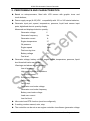
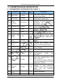
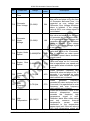
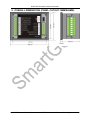
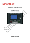
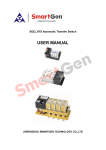
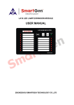
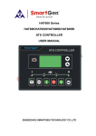
HGM1780 Automatic Genset Controller USER MANUAL Smartgen Technology Smartgen Technology Co., Ltd No. 28 Jinsuo Road Zhengzhou Henan Province P. R. China Tel: 0086-371-67988888/67981888 0086-371-67991553/67992951 0086-371-67981000(overseas) Fax: 0086-371-67992952 Web: http://www.smartgen.com.cn http://www.smartgen.cn Email: [email protected] All rights reserved. No part of this publication may be reproduced in any material form (including photocopying or storing in any medium by electronic means or other) without the written permission of the copyright holder. Applications for the copyright holder‟s written permission to reproduce any part of this publication should be addressed to Smartgen Technology at the address above. Any reference to trademarked product names used within this publication is owned by their respective companies. Smartgen Technology reserves the right to change the contents of this document without prior notice. Software Version Date Version Note 2009-11-20 1.0 Original release. 2010-05-31 1.1 Optimize details in Manual. 2010-07-21 1.2 Add alternator poles. 2010-11-05 1.3 Add function of setting parameters via front panel and over current alarm when loading. 2011-06-16 1.4 Add over-current action option. 2011-12-24 1.5 Modify Typical Application. 2012-10-30 1.6 Modify case dimension. 2013-04-03 1.7 Add the description of sensor digital input. HGM1780 Automatic Genset Controller CONTENT 1. OVERVIEW .................................................................................................... 4 2. PERFORMANCE AND CHARACTERISTICS ............................................... 5 3. SPECIFICATION ............................................................................................ 7 4. OPERATION .................................................................................................. 8 4.1. PANEL KEYS ............................................................................................. 8 4.2. LCD ICONS ................................................................................................ 8 4.3. DISPLAY DESCRIPTION ........................................................................... 9 4.4. OPERATION INSTRUCTION ..................................................................... 9 5. PROTECTION .............................................................................................. 12 6. PARAMETER RANGE AND DEFINITION ................................................... 13 6.1 PARAMETERS CONFIGURATION (TABLE 1) ........................................ 13 6.2 DEFINITION OF RELAY OUTPUTS (TABLE 2) ....................................... 17 6.3 DEFINITION OF DIGITAL INPUTS (ACTIVE WHEN CONNECT TO GND (B-)) (TABLE 3) ......................................................................................................... 17 6.4 SENSOR SELECTION (TABLE 4)............................................................ 18 6.5 CONDITIONS OF CRANK DISCONNECT (TABLE 5) .............................. 19 7. PARAMETER SETTING .............................................................................. 20 8. CONNECTIONS ........................................................................................... 22 9. OVERALL DIMENSIONS (PANEL CUTOUT 78MMX66MM) ...................... 23 10. TYPICAL APPLICATION ............................................................................. 24 HGM1780 Automatic Genset Controller ISSUE 2013-04-03 Version1.7 Page 3 of 24 HGM1780 Automatic Genset Controller 1. OVERVIEW HGM1780 is a genset automatic start module with 3 working modes that can be selected from the front panel. It can detect one-phase generator voltage and current, can be started and stopped manually or via a remote start/stop signals. In case of faults (such as low oil pressure, high water/cylinder temperature, emergency stop alarm, over speed), HGM1780 can automatically disconnect fuel relay and close ETS electromagnet to stop the generator. Graphical LCD monitor on the front panel displays fault conditions and provides effective alarm signals. HGM1780 Automatic Genset Controller ISSUE 2013-04-03 Version1.7 Page 4 of 24 HGM1780 Automatic Genset Controller 2. PERFORMANCE AND CHARACTERISTICS ◆ Based on microprocessor, fitted with LCD screen with graphic icons and touch-buttons; ◆ Power supply range (8~35)VDC,compatibility with 12V or 24V starter batteries; ◆ Generator input port; speed, temperature, pressure, liquid level sensor input ports; digitalized electric quantity display. Measured and displayed electric quantity: Generator voltage V Generator frequency Hz Generator current A Engine temperature ºC Oil pressure kPa Engine speed rpm Total running time H Battery voltage V Fuel level % ◆ Generator voltage, battery voltage, engine speed, temperature, pressure, liquid level threshold value can be set. Warnings and alarms are as following: Low oil pressure High water/cylinder temperature Over/under speed Emergency shutdown Fail to start Fail to stop Generator over/under voltage Generator over/under frequency Battery over/under voltage Load over current Low fuel level ◆ Idle control and ETS function (must be configured); ◆ 3 working modes: manual, auto, stop; ◆ The controller can be set as an engine controller via software (generator voltage HGM1780 Automatic Genset Controller ISSUE 2013-04-03 Version1.7 Page 5 of 24 HGM1780 Automatic Genset Controller input is deactivated) and used as water pump unit controller; ◆ Running status and alarm status are indicated by red LED on the panel; ◆ Compatibility with multiple temperature, pressure, fuel level sensors, which can be user-defined and used directly; temperature sensors, pressure sensors can be used in parallel with annunciator, providing digital data and increasing protection level at the same time; ◆ Multiple crank disconnect conditions to select (engine speed sensor, oil pressure, generator); ◆ 2 fixed relay outputs (fuel relay, start relay); ◆ 1 configurable output port which can be set as common alarm output, fail to stop output, preheat output or idle control output; ◆ Parameters can be set and modified by users and saved in internal FLASH storage, which means that they will not be lost in case of power off. All parameters of the controller can be modified using the front panel or through configurable LINK port via PC software (SG72 adapter, produced by our company must be used). All parameters can be set via computer using one USB port of the computer, which also allows to avoid batteries: power supply for the controller can come directly from the PC USB port. ◆ HGM1780 combines modular design, anti-flaming ABS plastic case, embedded installation, compact structure, small size, SCM control, stable performance and convenient operation. HGM1780 Automatic Genset Controller ISSUE 2013-04-03 Version1.7 Page 6 of 24 HGM1780 Automatic Genset Controller 3. SPECIFICATION Item Content Working Voltage DC8. 0V to 35. 0V, Continuous Power Supply Power Consumption Standby mode: 12V: 0.3W, 24V: 0.4W Working mode: 12V: 1W, 24V: 1.1W Alternator Input 1P2W 15V AC ~ 360 V AC (ph-N) voltage Alternator Frequency Magnetic Pickup Voltage Magnetic Pickup Frequency Max. accumulative run time 50/60Hz 1V to 24V (RMS) Max. 10kHz 99999.9 hours (After decimal point there is 1/10 of an hour, and it changes every six minutes) Start Relay Output 1Amp DC28V DC B+ power supply Fuel Relay Output 1Amp DC28V DC B+ power supply Programmable Relay 1Amp DC28V Output DC B+ power supply Digital Input Active when connected to B- Case Dimensions 90mm x 78mm x 44mm Panel Cutout 78mm x 66mm Working conditions Temperature: (-25~+70)ºC Humidity: (20~90)%RH without condensation Storage Condition Temperature: (-30~+80)ºC Protection Level Insulation Intensity Weight IP55: When waterproof rubber gasket installed between the controller and panel fascia. IP42: When waterproof rubber gasket is not installed between the controller and panel fascia. Object: among input/output/power Quote standard: IEC688-1992 Test way: AC1.5kV/1min Leakage current: 1mA 0.15kg HGM1780 Automatic Genset Controller ISSUE 2013-04-03 Version1.7 Page 7 of 24 HGM1780 Automatic Genset Controller 4. OPERATION 4.1. PANEL KEYS Key Definition Manual/Decrease Auto/Increase Stop Turn Page /Confirm Alarm Indicator Description Pressing this button will start the generator manually and place it into its manual mode; in settings menu moves cursor down and decreases the set value. Pressing this button will place the module into its auto mode; in settings menu moves cursor up and increases the set value. Pressing this button in any situation will shut down the generator and place it into its standby mode; in case of alarm, pressing this button will clear alarms. Using this button you can scroll pages of the LCD monitor; in settings menu press to move cursor and confirm. This indicator will flash when an alarm occurs. 4.2. LCD ICONS Icon Definition Icon Definition High Temp. Alarm Auto Mode Low Oil Pressure Stop Mode Over Speed Alarm Manual Mode Under Speed Alarm Gens Volts Indication Emergency Stop Battery Volts Indication Over Voltage Speed Unit (Per Minute) Under Voltage Oil Pressure Unit Fail to start Voltage Unit Fail to stop Fuel Level Unit (%) Voltage Abnormal Temperature Unit Auxiliary Alarm Frequency Unit Normal Run Hours Count Fuel Level Low HGM1780 Automatic Genset Controller A Load Current ISSUE 2013-04-03 Version1.7 Page 8 of 24 HGM1780 Automatic Genset Controller 4.3. DISPLAY DESCRIPTION Generator: phase voltage Ua, frequency F Oil pressure, water temperature Loading: current la, engine speed Liquid level %, accumulated run time Battery voltage, engine speed Parameters setting 4.4. OPERATION INSTRUCTION The module has three working modes: stop mode ( mode ( ), manual mode ( ) and auto ). ● Manual Start ( ) After pressing Manual Start button ( ) and holding it for at least one second, the indicator next to the button will be illuminated. Preheating output will be activated firstly and preheat delay begins. One second before it is finished, fuel output will be activated for one second and after that preheat output will be deactivated; starter is energized to output and engine cranks. When generator frequency reaches the pre-set value, the starter motor will be deactivated and generator will start. Then, safety delay will start, after it is finished, idle delay will start, and when it is finished idle relay will be closed and the generator will start working at normal speed. HGM1780 Automatic Genset Controller ISSUE 2013-04-03 Version1.7 Page 9 of 24 HGM1780 Automatic Genset Controller ● Auto Mode ( ) After pressing and holding button for at least one second, the indicator next to the button will be illuminated and the module will be placed into its automatic mode. If remote start signal is active (remote start input port is connected to B-), after start delay the genset will start. Preheating output will be activated firstly and preheat delay begins. One second before it is finished, fuel output will be activated for one second and after that preheat output will be deactivated; then starter is energized to output (engine will try to start according to the pre-set number of times; if one of the attempts is successful, the start process will be completed, otherwise fail to start alarm will be initiated: fail to start indicator on the panel will be illuminated and common alarm indicator will flash). After start delay and idle delay, idle relay will be deactivated and the generator will start working at normal speed. Note: During crank rest time, fuel output is deactivated; three seconds after the beginning of the delay, preheat and ETS outputs will be activated; after the end of the delay, ETS output will be deactivated and fuel relay output; preheat output will be deactivated before the beginning of crank. When remote start signal is deactivated, after stop delay, the generator enters idle state and the idle relay is deactivated. After idle delay, fuel relay deactivates, ETS relay output activates, and the genset automatically stops. After complete stop, ETS relay deactivates. ● Stop ( ) After pressing and holding for at least one second during normal operation of the genset (in manual or auto modes), the light indicator near the button will be illuminated and idle operation will begin. When idle relay deactivates and after idle delay, fuel relay is deactivated and ETS output is energized. When complete stop of the generator, ETS is deactivated. In case of fault alarm, pressing and holding the button for one second will clear alarms. Holding it for more than one second will illuminate all indicators on the panel (light test function). Pressing this button for more than one second in stop mode will lead to activation of ETS output and illumination of all the indicators on the panel (light test function). Releasing the button will immediately deactivate ETS output and light test function. HGM1780 Automatic Genset Controller ISSUE 2013-04-03 Version1.7 Page 10 of 24 HGM1780 Automatic Genset Controller When in stop mode, the module will only react to emergency stop signal. Note: Configurable output ports can be set as one of the following functions: “ETS output”, “Idle output” or “Preheat output” via PC. Therefore, all three functions can not be active at the same time; the above-mentioned is only to describe the logical course of action of the controller in case all three functions are active. HGM1780 Automatic Genset Controller ISSUE 2013-04-03 Version1.7 Page 11 of 24 HGM1780 Automatic Genset Controller 5. PROTECTION 1) Low Oil Pressure: detection begins after safety delay; if low oil pressure lasts for 2s, shutdown is initiated. 2) High Temperature: detection begins after safety delay; if high temperature lasts for 2s, shutdown is initiated. 3) Low Fuel Level: if fuel level stays below the pre-set level for 10 seconds, low fuel level warning signal is sent. Only warning and not shutdown. 4) Over Speed: detection begins after start; When speed over the preset for 2s, shutdown is initiated. 5) Under Speed: detection begins after idle delay; if under speed lasts for 15s, 6) 7) 8) 9) shutdown is initiated. Fail to Start: if after a pre-set number of crank attempts, the gen-set has not started, shutdown is initiated. Fail to Stop: if the generator has not stopped after stop delay, fail to stop warning is initiated, without latching. High Battery Voltage: if battery voltage stays above the pre-set value for 20 seconds, high battery voltage warning signal is sent. Only warning and not shutdown. Low Battery Voltage: if battery voltage stays below the pre-set value for 20 seconds, low battery voltage warning signal is sent. Only warning and not shutdown. 10) Emergency Shutdown: if emergency shutdown input is activated, ETS output is immediately energized while fuel, preheat and crank signals are deactivated and emergency shutdown alarm is initiated. 11) Generator Over Voltage: if it is detected that voltage is above the pre-set level for 5 seconds, generator over voltage signal is sent and shutdown alarm is initiated. 12) Generator Under voltage: if it is detected that voltage is below the pre-set level for 5 seconds, generator under voltage signal is sent and shutdown alarm is initiated. 13) Load Over Current: if load current stays above the pre-set value for a pre-set delay time, the controller will initiate over current alarm signal and A indicator will start flashing. 14) Common Alarm: in case of over speed, under speed, high temperature, low oil pressure, emergency shutdown, fail to start and fail to stop alarms, high battery voltage, low battery voltage, load over current or common alarm indicator flashing and common alarm output is activated HGM1780 Automatic Genset Controller ISSUE 2013-04-03 Version1.7 Page 12 of 24 HGM1780 Automatic Genset Controller 6. PARAMETER RANGE AND DEFINITION 6.1 PARAMETERS CONFIGURATION (TABLE 1) No. Parameter Range Default value P00 Start Delay (0-3600)s 1 P01 Stop Delay (0-3600)s 1 P02 Start Attempts (1-9) times 3 P03 Preheat Time (0-300)s 0 P04 P05 Cranking (3-60)s Time Crank Rest (3-60)s Time P06 Safety Delay On P07 Start Time Idle P08 8 10 Description Time from remote start signal is active to start genset. Time from remote start signal is deactivated to genset stop. The maximum number of crank attempts. If none of them is successful, the controller will initiate fail to start alarm. Time of pre-powering heat plug before starter is powered up. The time of powering up the starter for every crank attempt. The waiting time before second power up when engine start fail. Alarms for low oil pressure, high temperature, under speed, under frequency /voltage, charge fail are inactive. Idle running time of genset when starting. (1-60)s 10 (0-3600)s 0 Warming Up Time (3-3600)s 10 Warming time between genset switch on and normal running. P09 Cooling Time (3-3600)s 10 Radiating time before genset stop, after it unloads. P10 Stop Time (0-3600)s 0 Idle running time when genset stop. P11 ETS Solenoid (0-120)s Hold 20 P12 Fail to Stop (0-120)s Delay 0 P13 Flywheel Teeth P14 P15 Idle Power-on Mode Generator (10-300) (0-2) (0-20.0)s HGM1780 Automatic Genset Controller 118 0 10.0 The time of powering up the electromagnet during stop procedure. Time between ending of genset idle delay and stopped when “ETS time” is set as 0; Time between ending of ETS hold delay and stopped when “ETS Hold output time” is not 0. Tooth number of the engine, for judging of crank disconnect conditions and inspecting of engine speed. See the installation instructions. Default: Stop Mode. Alarm delay for generator over and ISSUE 2013-04-03 Version1.7 Page 13 of 24 HGM1780 Automatic Genset Controller No. Parameter Default value Range Abnormal Time Description under voltage states. P16 Generator Over Voltage (30-360)V 264 P17 Generator Under Voltage (30-360)V 196 P18 Engine Under (0-6000)RPM Speed 1200 P19 Engine Over (0-6000)RPM Speed 1710 P20 Under Frequency (0-75.0)Hz 45.0 P21 Over Frequency (0-75.0)Hz 57.0 P22 High Temperature (80-140)ºC 98 HGM1780 Automatic Genset Controller When generator voltage exceeds this value and stays so for the time of „Generator Abnormal Time‟, it is regarded as over voltage and Generator Over Voltage shutdown alarm is initiated. If the voltage value is 360V, over voltage signal is not initiated. When detected voltage falls below this value and stays so for the time of „generator abnormal state delay‟, it is regarded as under voltage and generator abnormal state shutdown alarm is initiated. If the voltage value is 30V, under voltage signal is not initiated. When engine speed falls below this value and stays so for 10 seconds, this is regarded as under speed and under speed alarm shutdown signal is sent. When engine speed exceeds this value and stays so for 2 seconds, this is regarded as over speed and over speed alarm shutdown signal is sent. When generator frequency falls below this value and stays so for 10 seconds, it is regarded as under frequency and under frequency alarm shutdown is initiated. When generator frequency exceeds this value and stays so for 2 seconds, it is regarded as an over frequency and over frequency alarm shutdown is initiated. When the temperature value of the external temperature sensor exceeds this threshold, high temperature signal is sent. Detection starts after safety delay and only concerns external temperature sensor which connected to the temperature sensor input port. If the set value is 140, high temperature signal will ISSUE 2013-04-03 Version1.7 Page 14 of 24 HGM1780 Automatic Genset Controller No. Parameter Range Default value P23 Low Oil (0-400)kPa Pressure 103 P24 Low Level (0-100)% 10 P25 Poles (2-16) 4 P26 Battery Over (12-40)V Volts 33.0 P27 Battery Under Volts 8.0 P28 P29 Liquid (4-30)V Current (5-6000)/5 Trans. Full Current (5-1900)A Rating 500 500 P30 Over Current (50-130) Percentage 120 P31 Over Current (0-3600)s Delay 1296 P32 Relay Output (0-6) 1 P33 Digital Input (0-6) 4 P34 Digital Delay (0-20.0)s Input HGM1780 Automatic Genset Controller 2.0 Description not be sent (this only concerns temperature sensor, not high temperature signal via config. input port). When the external pressure sensor value falls below this threshold, low oil pressure delay begins. Detection begins after safely on delay. If the set value is 0, low oil pressure signal is not sent (this only concerns pressure sensor and does not concern low oil pressure warning signal via configurable input port) When the liquid level of the external sensor falls below this value and stays so for 10 seconds, low liquid level signal is send and warning without shutdown is initiated. Numbers of generator pole, When battery voltage exceeds this value and stays so for 20 seconds, Battery Over Volts signal is send and warning without shutdown is initiated. When battery voltage falls below this value and stays so for 20 seconds, Battery Under Volts signal is send and warning without shutdown is initiated. The ratio of external CT. Default value: 500:5. Generator‟s rated current; used to estimate load over current. When load current exceeds full current value multiple by this value, over current delay begins. When load current exceeds this threshold and stays so for the pre-set time, the situation is regarded as over current. Default: Common Alarm Default: Auxiliary shutdown; if the set value is 0, fuel level sensor type can be selected. Active delay time for digital input ports ISSUE 2013-04-03 Version1.7 Page 15 of 24 HGM1780 Automatic Genset Controller No. P35 P36 P37 P38 Parameter Module Address Crank Disconnect Condition Disconnect Engine Speed Disconnect Generator Freq Default value Range (1-254) 1 (0-5) See table 5. 1 (0-3000) RPM 360 (10-30) Hz 14.0 Description Communication address Starter motor disconnection condition. There are 3 conditions of disconnecting starter with engine. Each condition can be used alone and simultaneously to separating the start motor and genset as soon as possible. When generator speed higher than the set value, starter will be disconnected. When generator frequency higher than the set value, starter will be disconnected. P39 Disconnect Oil Pressure (0-400) kPa 200 When generator oil pressure higher than the set value, starter will be disconnected. P40 Temperature Sensor (0-10) 06 SGD (120ºC resistor type) P41 Oil Pressure (0-10) Sensor 06 SGD (10Bar resistor type) P42 Fuel Level (0-7) Sensor 0 Not used. (If fuel level sensor is used, then the digital input port must be set as „not used‟. P43 Over Current (0-2) Action 0 0: Warn; 1: Shutdown; 2:Trip HGM1780 Automatic Genset Controller ISSUE 2013-04-03 Version1.7 Page 16 of 24 HGM1780 Automatic Genset Controller 6.2 DEFINITION OF RELAY OUTPUTS (TABLE 2) No. Items 0 Not used 1 2 3 4 5 6 Description Output is not active. Includes all shutdown alarms and warning alarms. Warning Common alarms are not self-latching, while shutdown alarms are and will Alarm not disappear until they are reset. Suitable for the genset with stop electromagnet. The Energized to electromagnet closes when stop idle is over. And opens when Stop EST delay is over. Used for machines that have idle mode. Closes during Idle control cranking, disconnects during warming up, closes during stop idle delay, disconnects after complete stop. Preheat It closes before starting and opens before starter is power on. control Closing During normal operation of the generator, closes the breaker Gens Reserved 6.3 DEFINITION OF DIGITAL INPUTS (ACTIVE WHEN CONNECT TO GND (B-)) (TABLE 3) No. 0 1 2 3 4 Digital Inputs 5 Description Notes Not Used High Temperature If these signals are activated after crank Input disconnect, shutdown alarm will be Low OP Warning immediately initiated. Input Only warning and not stops if this input is Reserved active. Shutdown alarm will be immediately Auxiliary Shutdown initiated if this input is active. When the gen-set is working normally and this signal is activated, if there is a high temperature situation, the controller will first High Temperature cool down the generator and then stop it; if Stop Input the signal is deactivated and a high temperature situation occurs, the controller will shut down the gen-set without cooling down. 6 Reserved 7 Reserved 8 Fuel Level Sensor HGM1780 Automatic Genset Controller See Table 4. ISSUE 2013-04-03 Version1.7 Page 17 of 24 HGM1780 Automatic Genset Controller 6.4 SENSOR SELECTION (TABLE 4) Items Temperature Sensor Oil pressure Sensor Fuel Level Sensor Content 0 Not used 1 Digital closed 2 Digital open 3 User defined resistor type 4 VDO 5 SGH (yellow river sensor) 6 SGD (Dongkang sensor ) 7 CURTIS 8 DATCON 9 VOLVO-EC 10 SGX 120 DEGREE 0 Not used 1 Digital closed 2 Digital open 3 User defined resistor type 4 VDO 5 SGH (yellow river sensor) 6 SGD(Dongkang sensor ) 7 CURTIS 8 DATCON 10Bar 9 VOLVO-EC 10 SGX 10Bar 0 Not used 1 Digital closed 2 Digital open 3 User defined resistor type 4 SGH (yellow river sensor) 5 SGD (Dongkang sensor ) 6 Reserved 1 7 Reserved 2 HGM1780 Automatic Genset Controller Remark Digital closed and Digital open both are digital signal; low or high electrical level can be selected to be active, connecting to earth point will mean that low electrical level is selected, hang in air means high electrical level is selected; can not be connected to power supply positive. The range of user-defined resistor type sensor is 0-999.9 Ohm, by default SGD sensor is selected. Digital closed and Digital open both are digital signal; low or high electrical level can be selected to be active, connecting to earth point will mean that low electrical level is selected, hang in air means high electrical level is selected; can not be connected to power supply positive. The range of user-defined resistor type sensor is 0-999.9 Ohm, by default SGD sensor is selected. Digital closed and Digital open both are digital signal; low or high electrical level can be selected to be active, connecting to earth point will mean that low electrical level is selected, hang in air means high electrical level is selected; can not be connected to power supply positive. The range of user-defined resistor type sensor is 0-999.9 Ohm, by default “Not used” is selected Before selecting fuel level sensor type, digital input type must be set as 0. ISSUE 2013-04-03 Version1.7 Page 18 of 24 HGM1780 Automatic Genset Controller 6.5 CONDITIONS OF CRANK DISCONNECT (TABLE 5) No 0 Content Magnetic Pickup 1 Generator Frequency 2 Magnetic Pickup + Generator Frequency 3 Magnetic Pickup + Oil pressure 4 Generator Frequency + Oil pressure 5 Generator Frequency + Magnetic Pickup+ Oil pressure 1. There are 3 conditions to make starter separate with engine, magnetic pickup, generator frequency can be used separately while oil pressure must be used together with magnetic pickup and generator frequency. The aim is to disconnect the starter motor as soon as possible. 2. Magnetic pickup is the magnetic equipment which be installed in starter for detecting flywheel teeth. 3. When set as magnetic pickup, must ensure that the number of flywheel teeth is as same as setting, otherwise, “over speed shutdown” or “under speed shutdown” may be caused. 4. If genset without magnetic pickup, please don‟t select corresponding items, otherwise, “start fail” or “loss speed signal” maybe caused. 5. If genset without oil pressure sensor, please don‟t select corresponding items. 6. If not select generator frequency in crank disconnect setting, controller will not collect and display the relative power quantity (can be used in water pump set); if not select magnetic pickup in crank disconnect setting, the rotating speed displayed in controller is calculated by generator signal. HGM1780 Automatic Genset Controller ISSUE 2013-04-03 Version1.7 Page 19 of 24 HGM1780 Automatic Genset Controller 7. PARAMETER SETTING 1) Pressing and simultaneously in generator standby mode will lead to the password interface (as shown below); when the first digit is blinking, enter the password 0318; 2) Press button to increase the value of the blinking digit and the value; when the first digit is set, press to decrease to move the cursor; 3) Repeat the same procedure to set the digits from 2nd to 4th; 4) If the password is right, enter into the parameter configuration interface (as shown below) which including the serial number of the set items and their parameters; press 5) Press to scroll up and to scroll down; to set the current item, and when the first digit starts blinking, use the same way that is used for password to enter the set value. Password: Parameter Setting: Attention: 1) Please change the controller parameters when generator is in standby mode only (e. g. Crank disconnect conditions selection, configurable input, configurable output, various delay), otherwise, shutdown and other abnormal conditions may happen. 2) The value of each parameter can be set only within a certain range. 3) Over voltage set value must be higher than under voltage set value, otherwise over voltage and under voltage condition may occur simultaneously. 4) Over speed set value must be higher than under speed set value, otherwise over speed and under speed condition may occur simultaneously. 5) Please set the generator frequency value as low as possible when cranking, in order to make the starter be separated quickly as soon as crank disconnect. 6) Consult the table 1 for serial numbers of the parameters. 7) Before selecting fuel level sensor type, it is necessary to set a configurable input port type as 0. HGM1780 Automatic Genset Controller ISSUE 2013-04-03 Version1.7 Page 20 of 24 HGM1780 Automatic Genset Controller ﹡Remark 1: Pressing button during parameter setting will immediately exit the set parameter. ﹡Remark 2: If the generator is in manual mode and crank disconnect condition is set as 2 (magnetic pickup + generator frequency) or 5 (generator frequency + magnetic pickup + oil pressure) and generator frequency and speed are NOT equal to zero, pressing and holding and for 0.5 seconds will lead to the controller automatically adjusting the flywheel teeth number according to generator frequency and generator poles number. HGM1780 Automatic Genset Controller ISSUE 2013-04-03 Version1.7 Page 21 of 24 HGM1780 Automatic Genset Controller 8. CONNECTIONS ◆ Terminal 1 (B-): Connect to the negative of the start battery. ◆ Terminal 2 (B+): Connect to the positive of the start battery. ◆ Terminal 3 (Em. stop input):Emergency stop input (active when connect to B+), external connect to emergency shutdown normally closed button. ◆ Terminal 4 (Fuel Output): Fuel output port (output B+), external connect to fuel relay, contactor capacity 1A. ◆ Terminal 5 (Start Output): Start output port (output B+), external connect to start relay, contactor capacity 1A. ◆ Terminal 6 (Remote Start Input): Remote start input, active when connected to B-. ◆ Terminal 7 (Configurable Input): Configurable input port, can be configured as digital signal or fuel level sensor signal; digital input active when connected to B-. ◆ Terminal 8 (Oil Pressure Input): Low oil pressure or sensor signal input port, active when connected to B-. ◆ Terminal 9 (Engine Temp Input): High water/cylinder temperature or sensor input port, active when connected to B-. ◆ Terminals 10 (L), 11(N): External connect to generator voltage signal to judge successful start and provide over and under speed protection. ◆ Terminal 12 (Load(I*)): Load current (inlet wire). ◆ Terminal 13 (Load(I)): Load current (outlet wire). ◆ Terminal 14 (Configurable Output): Configurable output port (output B+), can be configured via PC, contactor capacity 1A. ◆ Terminal 15 (Magnetic pickup): Magnetic pickup signal input, shielded wire is recommended. ◆ PC configurable socket (LINK): Connect to SG72 module and PC via USB port for parameter setting. HGM1780 Automatic Genset Controller ISSUE 2013-04-03 Version1.7 Page 22 of 24 HGM1780 Automatic Genset Controller 9. OVERALL DIMENSIONS (PANEL CUTOUT 78MMX66MM) HGM1780 Automatic Genset Controller ISSUE 2013-04-03 Version1.7 Page 23 of 24 HGM1780 Automatic Genset Controller 10. TYPICAL APPLICATION HGM1780 Automatic Genset Controller ISSUE 2013-04-03 Version1.7 Page 24 of 24