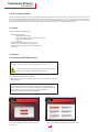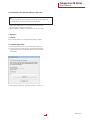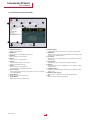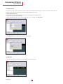
1
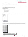
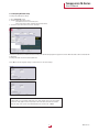
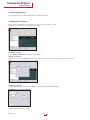
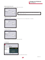
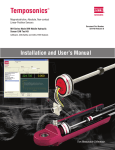
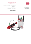
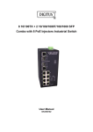
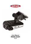
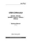
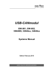
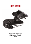
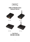
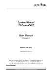
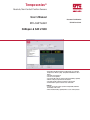
Temposonics®
Absolute, Non-Contact Position Sensors
User‘s Manual
Document Part Number
MH-CAN Testkit
551292 Revision A
CANopen & SAE J1939
• Kit includes the CAN Test Interface software with a user friendly
Graphical User Interface (GUI). Compatible with Windows® XP or
higher.
• Selectable sensor protocol
• Sensor search capability
• Sensor node ID, baud rate and cycle time programming capability
• Numerical display of position and velocity data
• Selectable graphical display of position or velocity data
• Print function to capture record of sensor verification
BENEFITS:
• Isolates sensor from vehicle system to independently determine
functionality of the sensor
• Allows troubleshooting capability with access to status byte data
Temposonics M-Series
User‘s Manual
1. M-Series CAN Test Software
The M-Series CAN Test Interface software supports CANopen, CANopen Safety and SAE J1939 sensor outputs. These different protocols can be selected
directly from the CAN Test Interface GUI. The CAN Test Kit AC/DC convertor provides power directly to the sensor, isolating it from the rest of the vehicle.
This is useful in situations where a vehicle harness is mis-wired or an error in the software makes the sensor appear to be malfunctioning. By isolating the
sensor, the operator can quickly verify if it is functioning properly. This eliminates time wasted on replacing a functional sensor.
1.1 Contents
The M-Series CAN Test Software includes:
• PCAN USB Kit, including:
- PCAN adapter with USB port
- Connection to CANbus via D-Sub, 9 pin (acc. CiA® 102)
- PCAN product CD with drivers
- USB cable
• M12 test cable with D-Sub, 9 pin connector end
• Pigtailed test cable with D-Sub, 9 pin connector end
• Multi-plug 12 Vdc power supply with power plug adapters
• Carrying case
2. Installation
2.1 Installation of USB-CANmodul Drivers
Note:
This software has to be installed on a PC using Windows XP or above.
In order to avoid errors during installation, please disconnect all USB-CAN
modules from the PC before starting the installation process.
1. Insert the PCAN Product CD into the CD drive.
2. Open the appropriate drive in the windows explorer and start the installation programme
Peak Oem Drv.exe.
Note:
1. If the installation program does not start automatically, use the Windows explore
function and browse to the appropriate drive and path of the USB-CANmodul Utility
drivers directory, then double-click ‘Intro.exe’ to start the installation.
2. Wait for the prompt to disconnect all USB-CANmoduls.
3. To install the PCAN USB drives follow the instructions.
MTS Sensors
4. Choose Drive PCAN USB, PCAN USB Hub to install the drives
2
Temposonics M-Series
User‘s Manual
2.2 Installation of Test-Software CANopen / SAE J 1939
Note:
1. In order to provide our customers with an up-to-date version, the software can
be downloaded at our website (www.mtssensor.de/login.html).
1. Start the MTS-CANtest-Interface..xx.exe-file after download and follow
the instructions for installation of the software.
2. After the installation, a desktop icon and a start menu entry are created.
3. Operation
3.1 Startup
Double-click the desktop icon to start the CAN Test Interface software.
3.2 Software Registration
1. On the first startup the needs to be unlocked by using a software key.
2. In order to obtain the software key, please provide the MTS application
support with the unique system-identifier, which appears on the display
on first startup.
3. After applying the software key, the CAN Test Software is ready for use.
3
MTS Sensors
Temposonics M-Series
User‘s Manual
3.3 Familiarizing yourself with the GUI
1
5
9
4
3
2
6
7
8
10
14
15
16
19
13
11
12
1. CAN Hardware Interface
Displays software revision
2. CAN Protocol
Allows selection of specific CAN output protocol
3. Baud Rate
Allows selection of sensor baud rate
4. Node ID
Allows selection of sensor Node ID
5. Start Test
‘Start Test’ button initializes sensor output
display on the CAN Test Interface
6. Stop Test
‘Stop Test’ button stops the display of
sensor information on the CAN Test Interface
7. Search for Sensor
‘Search’ button allows selective or auto search of the sensor connected
to the USB-CANmodul
8. Position Display
Displays sensor position output in mm
9. Velocity Display
Displays sensor velocity output in mm/s
MTS Sensors
10. Graphical Display
Displays running measurement of sensor position or velocity output
11. Setup Graph
Allows the user to change the Y-Axis Maximum, Y-Axis Mininum and
buffer size of the graphing window
12. Reset Graph
Allows the user to reset graph default Y-Axis and buffer size and clear
the data buffer
13. Graph Channel
Select either position or velocity data to display in the graph
14. Messages
Displays messages for user regarding the sensor and the software
communication
15. Communication Log
Displays the raw communication data between the CAN Test software
and the sensor
16. Modify Parameter (Sensor)
Allows the user to program the sensor node ID and baud rate
17. Print
Print the contents of the message window
4
Temposonics M-Series
User‘s Manual
3.4 Input Sensor Parameters
For sensor testing the software has to be configurated to the senor‘s CAN parameters.
3.4.1 Selecting Sensor Protocol
1. Select the down arrow on the Protocol Menu. The drop down menu will display all available CAN protocols.
Use the mouse to select the desired protocol.
2. Click the highlighted CAN protocol to choose it.
The software is able to determine the CAN protocol used by choosing the option
Determine my protocol
3.4.2 Selecting Sensor Baud Rate
1. Select the down arrow on the Baud Rate Menu. The drop down menu will display all available Baud Rates. Use the mouse to highlight the desired rate.
2. Click the highlighted Baud Rate to select it.
3.4.3 Input Sensor Node ID
1. Click the mouse cursor inside the node ID text box.
2. Enter in the desired sensor node ID.2.
3. Select ‘Start Test’ to begin the CAN sensor test.
5
MTS Sensors
Temposonics M-Series
User‘s Manual
3.5 Sensor Search
The steps in the previous section assume that the user knows both the baud rate and node ID configuration of the sensor being tested. If these values are
not known, the user can use the search function to find the current configuration of the sensor.
1. Click ‘Search for Sensor’ button.
2. Click the down arrow on the Baud Rate Menu. The drop down menu will display all available baud rates.
3. Use the mouse to select the desired baud rate.
4. Click the highlighted baud rate to select it. If the baud rate of the sensor is not known select ‘All Baud Rates’.
5. Click ‘Start Search’ button to begin searching with the selected baud rate.
3.6 Start Test
1. Select ‘Start Test’ button to initialize the sensor output display on the CAN Test Interface.
MTS Sensors
6
Temposonics M-Series
User‘s Manual
3.7 Communication Window
The communications window displays both summary and raw communications with the sensor.
3.7.1 Messages Tab
The messages tab is displayed in the communications window by default and displays the summary data of the sensor attached. If the messages tab is not
displayed, select the ‘Messages’ tab at the bottom of the communications window.
Information that is displayed includes:
• Timestamp of test
• CAN Protocol Selected
• Baud Rate
• Node ID
• Communications Verification
• Sensor Serial Number
• Sensor Firmware Revision
• Data Transfer Verification
• Transmission Type
To print a record of the displayed information, select the ‘Print’ button below the communications window. A local printer or network printer is required.
3.7.2 Communications Log Tab
The communications log tab displays the raw communications data between the CAN Test Interface and the attached sensor. To view the Communications
Log. Select the ‘Communications Log’ tab at the bottom of the communications window.
Note:
Under normal use this information will not be needed. This is made available for
advanced users and for troubleshooting with the factory.
7
MTS Sensors
Temposonics M-Series
User‘s Manual
3.8 Graphing Window
The graphing window displays a rolling display of the sensor output data.
3.8.1 Position
To view the graphical representation of the sensor position output:
1. Select the radio button to the left of ‘Position’ in the Graph Channel box under the graphing window.
3.8.2 Velocity
To view the graphical representation of the sensor velocity output:
1. Select the radio button to the left of ‘Velocity’ in the Graph Channel box under the graphing window.
MTS Sensors
8
Temposonics M-Series
User‘s Manual
3.8.3 Graphing Window Setup
To change the graph display settings:
1. Select ‘Setup Graph’ button.
2. To input a fixed scaling for the Y-axis:
a. Uncheck the box to the left of ‘Autoscale’.
b. Enter in the desired Y-Axis maximum and minimum values.
3. To return to autoscale check the box next to ‘Autoscale’.
The buffer size determines the maximum number of data points that will be displayed in the graph in the X-axis. When the buffer is full the oldest data will
be discarded.
To change the buffer size enter the desired buffer size.
Select ‘OK’ to save the new graph settings or Select ‘Cancel’ to cancel the changes.
Note:
If a large buffer size is selected the graph may not be easily viewed on the screen as the buffer
becomes full. If the graph becomes compressed in the x-axis reduce the buffer size until the
graph rolls easily on the screen. Recommended buffer size is between 10 - 100000.
9
MTS Sensors
Temposonics M-Series
User‘s Manual
3.8.4 Reset Graph Settings
Select ‘Reset Graph’ button to return the graph settings to the default configuration.
3.9 Modifying Sensor Settings
Main parameters in the CAN protocol are the baud rate, the node ID of the sensor and the cycle time.
The CAN Test Interface allows for the modification of these values.
To modify the parameters:
1. Select ‘Modify Parameters’ button to change the sensor settings.
Changing sensor node ID:
2. Click inside the text box under ‘Node ID’ and Enter in your node ID for the sensor. The value must be in hexadecimal format from 1-7F.
Changing sensor baud rate:
3. Click the down arrow on the Baud Rate menu. The drop down menu will display all available baud rates.
4. Use the mouse to select the desired rate.
5. Click the highlighted baud rate to select it.
MTS Sensors
10
Temposonics M-Series
User‘s Manual
Writing the new values to the sensor:
6. Select the ‘Write’ button and the sensor will be configured to the new values.
Note:
After rewriting the Node ID or the Baud Rate, the sensor needs to be disconnected and
reconnected to the power supply.
Changing sensor cycle time:
7. Click inside the text box under ‘Cycle Time’ and enter your cycle time for the sensor. The default value is 1 ms (decimal)
To cancel the value changes:
8. Select the ‘Close’ button to cancel changes and close the popup window.
3.10 Stop Test
Select the ‘Stop Test’ to stop the communication between the sensor and the CAN Test Software.
11
MTS Sensors
Document Part Number: 551292 Revision A (EN)
MTS and Temposonics® are registered trademarks of MTS Systems Corporation. All other trademarks are
the property of their respective owners. Printed in Germany.
Copyright © 2013 MTS Sensor Technologie GmbH & Co. KG. Alterations reserved. All rights reserved in all
media. No license of any intellectual property rights is granted. The information is subject to change without
notice and replaces all data sheets previously supplied. The availability of components on the market is subject to considerable fluctuation and to accelerated technical progress. Therefore we reserve the right to alter
certain components of our products depending on their availability. In the event that product approbations or
other circumstances related to your application do not allow a change in components, a continuous supply
with unaltered components must be agreed by specific contract.
MTS Sensor Technologie
GmbH & Co. KG
Auf dem Schüffel 9
58513 Lüdenscheid, Germany
Tel. + 49-23 51-95 87 0
Fax + 49-23 51-5 64 91
E-Mail: [email protected]
www.mtssensor.de
MTS Systems Corporation
Sensors Division
3001 Sheldon Drive
Cary, N.C. 27513, USA
Tel. + 1-919-677-0100
Fax + 1-919-677-0200
E-Mail: [email protected]
www.mtssensors.com
MTS Sensors Technology Corp.
737 Aihara-cho,
Machida-shi, Japan
Tel. + 81-42-775-3838
Fax + 81-42-775-5516
E-Mail: [email protected]
www.mtssensor.co.jp