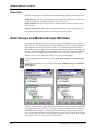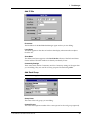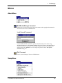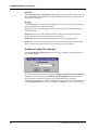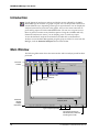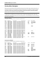
1
MultiModemManager
User Guide
MultiModemManager User Guide
P/N 82065502, Revision C
Copyright © 1997 by Multi-Tech Systems, Inc.
All rights reserved. This publication may not be reproduced, in whole or in part,
without prior expressed written permission from Multi-Tech Systems, Inc.
Multi-Tech Systems, Inc. makes no representation or warranties with respect to the
contents hereof and specifically disclaims any implied warranties of merchantability
or fitness for any particular purpose. Furthermore, Multi-Tech Systems, Inc. reserves
the right to revise this publication and to make changes from time to time in the content hereof without obligation of Multi-Tech Systems, Inc., to notify any person or organization of such revisions or changes.
Revision
Date
B
5/29/97
Reformatted; deleted compliance statements and references to Newt.
Description
C
9/15/97
Incorporated MultiModemManager 6.12 changes.
Multi-Tech, CommPlete, RASExpress, MCSI, MultiExpress, MultiExpress for DOS,
MultiModem, and the Multi-Tech logo are trademarks of Multi-Tech Systems, Inc.
MS-DOS and Windows are registered trademarks of Microsoft in the U.S. and other
countries. dBASEIII® is a trademark of Borland International. Other trademarks and
trade names mentioned in this publication belong to their respective owners.
Multi-Tech Systems, Inc.
2205 Woodale Drive
Mounds View, Minnesota 55112
(612) 785-3500 or (800) 328-9717
U.S. Fax (612) 785-9874
Technical Support (800) 972-2439
BBS (612) 785-3702 or (800) 392-2432
Fax Back (612) 717-5888
Internet Address: http://www.multitech.com
Software User License Agreement
MultiModemManager software is licensed by Multi-Tech Systems, Inc. to the original
end-user purchaser of the product, hereafter referred to as “Licensee.” The License includes the distribution diskette, other accompanying programs, and the documentation.
The MultiModemManager software, hereafter referred to as “Software,” consists of the
computer program files included on the original distribution diskette.
Licensee agrees that by purchase and/or use of the Software, he hereby accepts and
agrees to the terms of this License Agreement.
In consideration of mutual covenants contained herein, and other good and valuable considerations, the receipt and sufficiency of which is acknowledged, Multi-Tech Systems,
Inc. does hereby grant to the Licensee a non-transferable and non-exclusive license to use
the Software and accompanying documentation on the following conditions and terms:
The software is furnished to the Licensee for execution and use on a single computer system only and may be copied (with the inclusion of the Multi-Tech Systems, Inc. copyright
notice) only for use on that computer system. The Licensee hereby agrees not to provide
or otherwise make available any portion of this software in any form to any third party
without the prior express written approval of Multi-Tech Systems, Inc.
Licensee is hereby informed that this Software contains confidential proprietary and
valuable trade secrets developed by or licensed to Multi-Tech Systems, Inc. and agrees
that sole ownership shall remain with Multi-Tech Systems, Inc.
The Software is copyrighted. Except as provided herein, the Software and documentation
supplied under this agreement may not be copied, reproduced, published, licensed, sublicensed, distributed, transferred, or made available in any form, in whole or in part, to
others, without expressed written permission of Multi-Tech Systems, Inc. Copies of the
Software may be made to replace worn or deteriorated copies for archival or backup
procedures.
Licensee agrees to implement sufficient security measures to protect Multi-Tech Systems,
Inc. proprietary interests and not to allow the use, copying or transfer by any means,
other than in accordance with this agreement. Licensee agrees that any breach of this
agreement will be damaging to Multi-Tech Systems, Inc.
Licensee agrees that all warranties, implied or otherwise, with regard to this Software, including all warranties of merchantability and fitness for any particular purpose are expressly waived, and no liability shall extend to any damages, including consequential
damages, whether known to Multi-Tech Systems, Inc. It is hereby expressly agreed that
Licensee’s remedy is limited to replacement or refund of the license fee, at the option of
Multi-Tech Systems, Inc., for defective distribution media. There is no warranty for misused materials.
This package contains 3.5-inch disks. Neither this software nor the accompanying documentation may be modified or translated without the written permission of Multi-Tech
Systems, Inc.
This agreement shall be governed by the laws of the State of Minnesota. The terms and
conditions of this agreement shall prevail regardless of the terms of any other submitted
by the Licensee. This agreement supersedes any proposal or prior agreement. Licensee
further agrees that this License Agreement is the complete and exclusive statement of
Agreement, oral, written, or any other communications between Multi-Tech Systems, Inc.
and Licensee relating to the subject matter of this agreement. This agreement is not assignable without written permission of an authorized agent of Multi-Tech Systems, Inc.
CommPlete Communications Server
iii
iv
CommPlete Communications Server
Table of Contents
1 Introduction
Introduction .............................................................................................................................2
Description ...............................................................................................................................2
Typographic Conventions......................................................................................................3
2 Installation
Introduction .............................................................................................................................6
How to Install MultiModemManager ..................................................................................6
3 Configuration
Introduction .............................................................................................................................8
Viewing Local Modems..........................................................................................................8
Viewing Modems at Remote IP Sites....................................................................................9
Running MultiModemManager as a Supervisor ............................................................9
Viewing an Agent and Its Modems ..................................................................................9
Procedures for Setting Up Remote IP Sites ....................................................................10
4 Organizing and Configuring Your Modems
Organizing Your Modems....................................................................................................14
Rack Groups.......................................................................................................................14
Modem Groups..................................................................................................................14
Organization Procedures..................................................................................................14
Configuring Your Modems ..................................................................................................15
Configuration Planning ....................................................................................................16
Configuration Procedures ................................................................................................18
5 Security
Introduction ...........................................................................................................................24
Callback Security ...................................................................................................................24
Security Planning ..................................................................................................................26
Do You Need MultiModemManager Security? ............................................................26
Do You Need Pass-Through, Fixed Callback or Variable Callback Security?...........26
Do You Have Multiple Host Types that Users Need Access To? ...............................27
Do You Have Multiple Security Levels for Call-In Users? ..........................................28
Do You Require Users to Change Their Passwords?....................................................29
What Days and Times Are Users Allowed Access to the System? .............................30
What User Interface Do You Want to Present to Call-In Users? .................................30
Which Modems Should Be Dial-In, Dial-Out, or Both?................................................31
Security Procedures ..........................................................................................................32
6 Monitoring and Controlling Your System
Monitoring Your System ......................................................................................................38
Fault and Status Events Window ....................................................................................38
Call Traffic Window..........................................................................................................38
CommPlete Communications Server
v
Call Back Queue Window................................................................................................39
Rack Display Window......................................................................................................40
Modem Status Window....................................................................................................40
Controlling Your System......................................................................................................41
Configuring Modems .......................................................................................................41
Testing Modems ................................................................................................................41
Resetting Modems.............................................................................................................42
Hanging Up Modems .......................................................................................................42
Acting in Response to Faults ...........................................................................................42
Modem Control Procedures ............................................................................................42
7 The Manager
Introduction ...........................................................................................................................46
Main Window........................................................................................................................47
Menu Bar............................................................................................................................47
Toolbar................................................................................................................................48
Client Area .........................................................................................................................49
Status Bar............................................................................................................................50
Rack Groups and Modem Groups Windows ....................................................................50
Icon Colors .........................................................................................................................51
Opening and Closing an Object ......................................................................................51
Moving a Rack.................................................................................................................. .52
Moving a Modem..............................................................................................................52
Displaying Modem Information .....................................................................................53
Adding and Editing Objects ............................................................................................55
Mouse Shortcuts................................................................................................................59
Menu Commands..............................................................................................................59
Call Traffic Window .............................................................................................................60
Fault and Status Events Window........................................................................................62
Call Back Queue Window....................................................................................................63
Modem Usage Window .......................................................................................................63
Unmanaged Modems Configuration Window .................................................................64
Rack Display Window..........................................................................................................66
Modem Status Window........................................................................................................67
Menus .....................................................................................................................................71
About Menu.......................................................................................................................71
Setup Menu........................................................................................................................72
View Menu.........................................................................................................................93
Control Menu.....................................................................................................................94
Firmware Menu...............................................................................................................100
Rack Menu .......................................................................................................................101
Tools Menu ......................................................................................................................102
8 Statistical Analyzer
Introduction .........................................................................................................................106
Main Window......................................................................................................................106
File Menu..............................................................................................................................107
About Command.............................................................................................................107
Open Command ..............................................................................................................107
Print Command ...............................................................................................................107
Print Setup Command....................................................................................................107
Exit Command.................................................................................................................108
vi
CommPlete Communications Server
Edit Menu.............................................................................................................................108
Copy Command ..............................................................................................................108
View Menu ...........................................................................................................................108
Connections Command ..................................................................................................108
Disconnections Command .............................................................................................109
Faults Commands............................................................................................................109
Modem Usage Commands.............................................................................................109
Remote Modem Faults Command ................................................................................109
SNMP Information Command ......................................................................................109
General Graph Options Command...............................................................................109
Modem Usage Graph Options Command ...................................................................110
Ascii Log Command .......................................................................................................111
Search Menu.................................................................................................................... .....112
Find Command................................................................................................................112
Next Command ...............................................................................................................112
Analysis Menu .....................................................................................................................112
Analysis Process Command...........................................................................................113
Filter Modems Command ..............................................................................................116
Filter Calls Commands ...................................................................................................117
Report Menu .................................................................................................................... ....117
Connection History Command......................................................................................118
Connections by Modem Command ..............................................................................118
Connection Usage Command ........................................................................................118
Connection Statistics Command....................................................................................118
Fault Report by Modem Command..............................................................................118
Connections by Security ID Command ........................................................................118
Connections by Gateway ID Command.......................................................................118
Connections by All User IDs Command ......................................................................119
9 Configuration Manager
Introduction .........................................................................................................................122
Configuration File Format..................................................................................................122
Creating a Configuration File ............................................................................................124
Sending a Configuration File to a Remote Rack..............................................................124
Configuration File Templates ............................................................................................125
The Main Window ..............................................................................................................12 6
About Menu ..................................................................................................................... ....126
Configuration Manager Command ..............................................................................127
Exit Command .................................................................................................................12 7
File Menu...................................................................................................................... ........127
New Command ...............................................................................................................127
Open Command ..............................................................................................................127
Close Command ..............................................................................................................127
Save Command................................................................................................................128
Save As Command..........................................................................................................128
Record Menu........................................................................................................................128
Add Command ................................................................................................................128
Edit Command.................................................................................................................129
Delete Command.............................................................................................................129
Master List Command ....................................................................................................129
CommPlete Communications Server
vii
10 Security Database Editor
Introduction .........................................................................................................................132
Main Window......................................................................................................................133
File Menu..............................................................................................................................134
New Command ...............................................................................................................134
Open Command ..............................................................................................................134
Close Command ..............................................................................................................134
Save Command ...............................................................................................................135
Save As Command..........................................................................................................135
Print Command ...............................................................................................................135
Change Password Command ........................................................................................135
Import Command ...........................................................................................................135
Export Command............................................................................................................135
Exit Command.................................................................................................................136
The Edit Menu .....................................................................................................................136
Set Template Command.................................................................................................137
Cut Command .................................................................................................................137
Copy Command ..............................................................................................................138
Paste Command ..............................................................................................................138
Find Command................................................................................................................138
Find Next Command ......................................................................................................138
Find Previous Command ...............................................................................................138
Record Menu .......................................................................................................................138
Add Command................................................................................................................139
Edit Command ................................................................................................................141
Delete Command ............................................................................................................141
Help Menu ...........................................................................................................................141
Using Help Command....................................................................................................141
Security Database Command ........................................................................................141
About Security Database Command ............................................................................141
11 Solving Problems
Introduction .........................................................................................................................144
POST (Power On Self Test) ................................................................................................144
MultiModemManager Link Problems..............................................................................144
SNMP Problems ..................................................................................................................145
Fault and Status Messages .................................................................................................145
Messages and Recovery Procedures.................................................................................149
Diagnostic Tests...................................................................................................................158
12 Warranty, Service, and Technical Support
Limited Warranty................................................................................................................160
Technical Support ...............................................................................................................160
The Multi-Tech BBS ............................................................................................................160
Logging onto the Multi-Tech BBS .................................................................................160
Downloading a File.........................................................................................................161
Reading a Message..........................................................................................................162
Leaving a Message ..........................................................................................................162
Bulletins............................................................................................................................162
About CompuServe ............................................................................................................162
About the Internet...............................................................................................................162
viii
CommPlete Communications Server
About the Multi-Tech Fax-Back Service ...........................................................................164
Appendix A Reports
Introduction .........................................................................................................................168
ASCII Log Dump.................................................................................................................168
Connection Analysis ...........................................................................................................170
Connection Usage Report...................................................................................................171
Connection Statistics ...........................................................................................................171
User ID Reports ...................................................................................................................172
Fault Reports ........................................................................................................................172
Appendix B dBASEIII-Formatted Output
Introduction .........................................................................................................................174
Record Field Definitions.....................................................................................................174
Special Events (Nodeid = FF; Destid = FF) ......................................................................178
Command Events Sent from the Manager (Nodeid = FF, Destid != FF).....................179
Events Sent to the Manager (Nodeid != FF, Destid = FF) ................................................181
Index .................................................................................................................................183
CommPlete Communications Server
ix
x
CommPlete Communications Server
1 Introduction
CommPlete Communications Server
1
MultiModemManager User Guide
Introduction
MultiModemManager, model MMMSNMP, is a software suite that centralizes control and configuration of both rack-mounted modems and stand-alone or unmanaged
rack-mounted modems. It enables the administrator to change modem and rack configurations, analyze modem performance, control access to the modems for security,
and monitor all connections.
Description
MultiModemManager consists of four modules: the Manager, the Configuration
Manager, the Statistical Analyzer, and the Security Database Editor:
• The Manager provides organization of modems through rack groupings; visual
feedback on system status; control over callback security options, fault and alarm
status, and corrective actions; diagnostic tools for testing, verifying, and tracking
modem operation; and automated modem configuration.
The Manager tracks connections and faults in near-real time, giving you up-to-themoment troubleshooting and reporting information that allows you to respond to
minor problems before they cause major breakdowns.
• The Configuration Manager lets the administrator create custom configuration files
for modems, send AT commands, and set S-register values. Each modem is associated with a configuration file stored in flash memory on the rack controller card.
Because configuration files can be assigned to one or more modems, the configuration of a group of modems can be changed by editing a single file.
• The Statistical Analyzer performs statistical analyses of event data and generates
connection reports, log reports, and graphs of the analyzed event data. Reports
can include information on modem connections, system faults, and utilization.
Reports can be generated in ASCII, dBASEIII™, and ASCII-delimited formats.
• The Security Database Editor lets the administrator create and maintain a security
database of system users. The database can include user IDs, passwords, valid
dates and times of access, and security type.
2
CommPlete Communications Server
1
Introduction
Typographic Conventions
Certain typographic conventions have been adopted throughout the text of this manual to illustrate keyboard input, screen display dialogs, and special vocabulary.
• Text entered by you is shown in bold. Example: supervisor.
• Code examples and screen messages are shown in a monospace font.
• Italics are used for important new terms, for book and manual titles, and when
terminology is explained, introduced, or emphasized. Example: “The word bit is a
contraction of the words binary digit.”).
• Names of keyboard keys are shown in small caps. Example: SHIFT.
• Certain keys and key combinations may be abbreviated as follows:
<CR>
Means press the carriage return key, which can be represented on the
keyboard by a broken left-pointing arrow or the words Enter or Return.
The ENTER key, or carriage return, is often used to activate commands.
ALT+X
Means to hold down the ALT key while you press the key represented
by X.
CTRL+X
Means to hold down the CTRL (control) key while you press the key represented by X.
• Please notice the difference between the capital letter O and the number 0.
CommPlete Communications Server
3
MultiModemManager User Guide
4
CommPlete Communications Server
2 Installation
CommPlete Communications Server
5
MultiModemManager User Guide
Introduction
This chapter describes how to install MultiModemManager on a management workstation. The workstation should be attached to the same network as a MultiModemManager or CommPlete Communications Server rack. The minimum requirements
for the workstation are a 486DX/33 microprocessor, 8 MB of RAM, 50–100 MB of
hard disk space, a 3.5-inch floppy drive, an Ethernet network interface card (NIC) or
Arcnet card, a VGA monitor, a two-button mouse, and Windows 3.11, Windows 95,
or Windows NT 3.1 or higher.
MultiModemManager is provided on two 3.5" diskettes.
How to Install MultiModemManager
1.
Turn on the workstation and start Windows.
2.
Make a working copy of your MultiModemManager diskettes, label the copies,
and store the original diskettes in a safe place.
3.
Insert MMMDisk 1 into the workstation’s floppy drive.
4.
To run the Setup program, double-click on A:\SETUP.EXE using File Manager
or Windows Explorer.
Follow the instructions in the Setup program. By default, Setup copies the
MultiModemManager files to the directory C:\MRACK. If there is an existing
installation in this directory, then its executable files are updated. If not, a new
program group, called Rack Management, is added to the Program Manager or
the Start menu.
6
5.
The Rack Management program group contains icons for the Rack Manager; the
Configuration Manager; the Security Database Editor; the Statistical Analyzer;
and several Read Me files, which contain the most current information about
MultiModemManager.
6.
To start MultiModemManager, double-click on the Rack Manager icon.
CommPlete Communications Server
3 Configuration
CommPlete Communications Server
7
MultiModemManager User Guide
Introduction
This chapter is a guide to setting up MultiModemManager for use with your racks
and modems.
Viewing Local Modems
To start MultiModemManager, double-click the Rack Manager icon. The Manager
module’s main window appears.
When you first run MultiModemManager, the Rack Groups and Modem Groups
windows are open by default. (MultiModemManager saves the current desktop
when you exit.) Both windows display the same modems; however, the Rack Groups
window displays your modems by rack location, while the Modem Groups window
displays your modems by logical group. Each displays the organization of your modems as a hierarchy, with the top level being the world and the bottom level being
the modems; in between are the IP site, rack or modem group, and rack. In each window racks and modems are grouped into two boxes. The Unassigned Groups box
contains racks that have not been assigned to a defined group. The Defined Groups
box contains racks and modems in groups that have been defined by the system
administrator.
The first time you run MultiModemManager, all your racks are in the Unassigned
Groups boxes. The only IP site listed in the Unassigned Groups boxes is Local Site,
which contains racks that are connected to the management PC via an MIC link. To
display other IP sites, you must first define them by using the Add button (see page 55).
8
CommPlete Communications Server
3
Configuration
To display the Unassigned rack group, double-click Local Site in the Unassigned
Groups box. The Unassigned group should appear with a yellow icon, indicating
that there are active racks in the group. If the Unassigned group doesn’t exist or if
the group icon is gray, then MultiModemManager is having trouble communicating
with the racks attached to the group. For help on troubleshooting this kind of problem, see Chapter 11, “Solving Problems.”
If the Unassigned group is yellow, double-click it to display the active racks under it,
then double-click the racks to display the modems that are installed in them. From
this point you can display rack and modem information in several different ways.
To display
Click
A graphic view of the rack
A rack icon, then the Display button
A graphic view of the modem
A modem icon, then the Display button
A modem’s configuration file
The Display box, then Modem Configuration
A modem’s basic setup
The Display box, then Modem Inventory
Viewing Modems at Remote IP Sites
With MultiModemManager, you can view modems at remote sites, even half-way
around the world. It can act as an SNMP proxy agent for racks and modems that are
attached to it (it speaks SNMP for racks and modems that can’t on their own). A
MultiModemManager system that is running as an SNMP proxy is called an agent.
This section describes how a supervisor MultiModemManager can view modems
that are attached to agents on the same TCP/IP network.
Running MultiModemManager as a Supervisor
To run MultiModemManager as a supervisor, you must be able to ping an agent’s IP
address. If you are unable to ping the agent, see Chapter 11, “Solving Problems.”
When you can successfully ping the agent, run MultiModemManager. The title bar
shows your IP address and the mode you are running in. The default mode is
Supervisor. To change to Supervisor mode from another mode, select Setup|SNMP|
Mode|Supervisor. The title bar changes to reflect your selection.
Viewing an Agent and Its Modems
To view an agent, add it to the list of IP sites that MultiModemManager monitors. To
add an IP site, see “How to Add an IP Site” on the next page.
The IP icon of the new agent should be green. If it is not, see Chapter 11, “Solving
Problems.” To view the agent’s rack groups, double-click the icon for the IP site. You
can now perform the same actions on these remote modems as on local modems.
CommPlete Communications Server
9
MultiModemManager User Guide
Procedures for Setting Up Remote IP Sites
How to Set Up an Agent IP Site
1.
Run MultiModemManager and select Setup|SNMP|Mode|Agent.
2.
Select Setup|SNMP|Default Trap IP. In the Set Default Trap IP dialog box,
type the IP address of the MultiModemManager supervisor that will be monitoring the agent site.
How to Add an IP Site
1.
In the Rack Groups and Modem Groups windows, select a world icon, then click
Add.
2.
In the Add IP Site dialog box, type the IP address of the MultiModemManager
agent that you wish to view, and the long and short names for the site. The long
name is used in the titles of windows that display information about objects
from the site. The short name is used in the Fault and Status Events window to
identify the IP site where a fault or status occurred.
3.
Type the Get Community and Set Community settings to match the Get and Set
Community settings of the agent that you are adding. (These are used for security purposes.) The default is public.
4.
When you are finished, click OK. An IP site with the long name displayed
should appear in the Rack Groups and Modem Groups windows list boxes.
How to Edit an IP Site
1.
To edit an IP site’s information, find the IP site in either list box in the Modem
Groups or Rack Groups window.
2.
Click the IP site and then click Edit. You can change all the information for the
site except the IP address.
3.
To change a site’s IP address, delete the old site and then add a new site with the
new IP address and otherwise identical information.
Note: A CommPlete Communications Server IP site can be edited only in the Modem
Groups window.
How to Delete an IP Site
10
1.
To delete an IP site, find the IP site in either list box in the Modem Groups or
Rack Groups window.
2.
Click the IP site and then click Delete. This will close all windows and opened
hierarchies in the Rack Groups and Modem Groups windows related to the site.
CommPlete Communications Server
4 Organizing and Configuring
Your Modems
CommPlete Communications Server
11
RASExpress User Guide
Organizing Your Modems
The primary purpose of the Rack Groups and Modem Groups windows is to organize your modems so that they are easier to manage. The Rack Groups window shows
the physical organization of your modems, whereas the Modem Groups window
shows the logical organization of your modems. The basic unit of organization in
each window is the group.
To organize your groups, you can drag objects to and from them. In the Rack Groups
window you can drag only racks (modems always appear under the rack in which
they are physically installed). However, in the Modem Groups window, you can drag
both racks and modems (when you drag a rack, you are really dragging the modems
that are currently displayed under the rack).
Rack Groups
Rack groups show the physical organization of your racks and modems. Organizing
your racks into groups allows you to organize them by physical location. For example,
you might create the following rack groups: Sales Wiring Closet, Purchasing Wiring
Closet, and Administration Wiring Closet to indicate where the racks are located.
Note: CommPlete Communications Server rack groups are predefined and cannot be
changed, renamed, or moved.
Modem Groups
Modem groups allow you to organize your modems functionally or by any other
criteria you choose. An advantage of functional organization is that it allows modem
attributes to be set by group.
Click a modem group that you have created and then click Edit. In the Edit Modem
Group dialog box are options that can be set for the modems in the group, such as
when the modems get configured and whether modem events are saved to the event
file. You can also use modem groups to determine which modems users can call into
and get called back from.
See also: “Configuring Your Modems” on page 15.
Organization Procedures
How to Create a Rack or Modem Group
Note: Rack groups are predefined at a Complete Communications Server site.
12
1.
In the Defined Groups box, click the IP site to which you want to add a group.
2.
Click Add.
3.
Type the group name and, optionally, the name and phone number of the contact person for the group.
CommPlete Communications Server
4
4.
Organizing and Configuring Your Modems
Click OK.
How to Move Racks Between Rack Groups
Note: Does not apply to a Complete Communications Server site.
1.
If necessary, double-click the IP site and/or Unassigned group in the
Unassigned Groups box to display your racks.
2.
If necessary, double-click the IP site in the Defined Groups box so that the destination group is displayed.
3.
Using your mouse, drag the rack that you want to move from the source group
to the destination group.
How to Move Modems between Modem Groups
1.
Double-click the IP site and/or Unassigned group in the Unassigned Groups
box to display your racks.
2.
Double-click a rack in the Unassigned group to display the modems in the rack.
3.
Double-click the IP site and/or modem group in the Defined Groups box to
display the destination group.
4.
Select a modem and drag it from the source group to the destination group. The
rack that the modem are physically located in will appear above the modem in
the destination group. To select and move more than one modem at a time, you
must hold down the SHIFT key during the move.
Note: In the Modem Groups window, a rack can appear under more than one
modem group.
Configuring Your Modems
The MultiModemManager system is configurable and can be adapted to many different computing environments. Two types of modem parameters can be configured:
AT commands and Modem Inventory settings. Also, the condition upon which a
configuration is sent to the modems can be set by modem group..
The AT commands that are configured are the same commands that can be sent to
the modem through the modem’s serial port. The actual AT commands that are sent
depend on the intended purpose of the modem and the modem model; some newer
modem cards have different command sets than older models. AT commands can be
grouped together in a modem configuration file that can be used to configure modems used for similar purposes. E.g., the configuration file UNIX.CFG could contain
all the commands required by modems attached to a UNIX system. These files can be
created and edited by Configuration Manager. It is important to note that when these
sets of AT commands are sent to the modem, the modem is set first to the factory default settings, so the configuration files need only contain differences from the modem’s factory default setting.
CommPlete Communications Server
13
RASExpress User Guide
Modem Inventory settings include options that might be set by switches on the modem, such as whether the modem is to be a dial-up or leased-line, asynchronous or
synchronous, security or non-security modem. Modem Inventory cannot be configured at a CommPlete Communications Server site.
Configuration Planning
The following questions may be useful when configuring a MultiModemManager
system.
Are your modems connected to one type of host device or to
multiple types of host devices?
The host device is the device that is connected to the serial port of the modem. Examples of different types of host devices might be a UNIX system, an AS/400 system, a
terminal server, a remote node gateway, a fax server, etc. Different types of hosts can
require different modem configuration files and different Modem Inventory settings,
because different hosts can expect the modem to perform in different ways. It helps
to put modems that are connected to the same type of host in the same modem
group, so the Configure Options settings can be set the same for the modems.
Examples:
Host 1
A RASExpress server or a fax server needs no configuration because it reconfigures
the modem before and after every call.
Modem configuration file:
DEFAULT.CFG (not used)
Modem Inventory settings:
Asynchronous(default)
Dial-up (default)
None
Configuration Options settings for modem group Fax Server:
None (the fax server takes care of it).
Host 2
A UNIX system requires no responses from the modem unless given a command
from the UNIX system, and requires the serial port to be set to 19200 bps. Inbound
security is required.
Modem configuration file:
Q2 (for quiet answer settings)
$SB19200 (for a serial port speed of 19200 bps)
Modem Inventory settings:
Asynchronous (default)
Dial-up (default)
Inbound
Configuration Options settings for modem group UNIX:
On Disconnect (to make sure the modems are reconfigured after every call).
14
CommPlete Communications Server
4
Organizing and Configuring Your Modems
On Rack Power Up (to make sure the modems are reconfigured after the card is
installed).
See also:
• “How to Move Modems Between Modem Groups” on page 15.
• “How to Create or Edit Modem Configuration Files” on page 18.
• “How to Assign Configuration Files to Modems” on page 19.
• “How to Set Modem Inventory settings for Modems” on page 19.
• “How to Set Modem Group Configuration Settings” on page 19.
Are all the modems of the same type?
Modems are available for the MR4800 rack that meet two different standards: the
MT1432MR, a V.32bis modem with V.17 fax capabilities, and the MT2834MR/MR6, a
V.34 modem with V.17 fax capabilities. The CommPlete rack may have an
MT3334HD8, a 33.6k bps modem, and/or an MT5634HD8, a K56flex modem with a
different command set. AT commands that apply to one of these may not apply to the
other. For example, an MT2834MR/MR6 can be set with a modem baud rate of
28,800 bps by the command $MB28800, but the MT1432MR would give an error to
this command. Because different modems may require different configuration files,
you may want to put all modems of one type into one modem group and all modems
of another type into another modem group.
See also:
• “How to Move Modems between Modem Groups” on page 15.
• “How to Create or Edit Modem Configuration Files” on page 18.
• “How to Assign Configuration Files to Modems” on page 19.
Does the host system configure the modem?
Some host devices such as fax servers might initialize the modem before and after
every call, whereas other devices such as a terminal server might never configure the
modem. If the host does not configure the modem, then MultiModemManager
probably should. If the host does configure the modem, then MultiModemManager
must not. If both the host and MultiModemManager try to configure the modem at
the same time, the host will error out because the modem ignores all input from its
serial port while the MultiModemManager is configuring the modem. Host systems
that configure the modem could be put into one modem group and host systems that
don’t could be put into another.
See also:
• “How to Move Modems between Modem Groups” on page 15.
• “How to Set Modem Group Configuration Settings” on page 19.
What types of phone lines are the modems connected to?
There are two basic types of analog phone lines: leased lines (two-wire and fourwire) and dial-up lines. CommPlete Communications Servers have only digital T1 or
ISDN PRI termination.
Leased-lines are always connected directly at both ends, so the modems must be configured for leased-line operation by setting the Modem Inventory settings to 2-wire
Leased Line or 4-wire Leased Line as required. You also must set the modem to
Answer or Originate, whichever is the opposite of what the modem on the other end
is set to. Some modems can be connected to both a leased line and a dial-up line, so
CommPlete Communications Server
15
RASExpress User Guide
that if the leased line fails and the modem is set to Dial-Backup, it will call the other
modem on the dial-up line to reestablish the connection.
Note: Make sure that the modem group the leased line modem is in is set to configure the modem on reset and disconnect. This is because if the leased line drops or the
modem is reset, it will not try to reestablish the connection until it is configured
again.
Dial-up lines on host systems used for inbound calls are usually put into some sort of
call pool. That is, one phone number may be used to call a group of phone lines
(which are connected to a group of modems). When the phone number is called, the
first non-busy line is used to handle the incoming call. Modems that are connected to
such a call distribution should be set out-of-service (go off-hook) when the device
connected to its serial port is inactive. This ensures that incoming calls will not roll
over to this inactive device. One way to do this is to set up the S36 and S37 registers
in the modem configuration file so that when DTR is not high, the modem will automatically go out-of-service. See the ISP.TXT file in the MRACK directory or folder.
See also:
• “How to Move Modems between Modem Groups” on page 15.
• “How to Set Modem Group Configuration Settings” on page 19.
• “How to Set Modem Inventory settings for Modems” on page 19.
Configuration Procedures
How to Create or Edit Modem Configuration Files
Use the Configuration Manager to create and edit modem configuration files. (You
can access it by either double-clicking the Configuration Manager icon in the Rack
Management group, or by clicking the Configuration Manager button on the right
side of the Manager toolbar.) Create only one configuration file for each type of configuration that you need. The configuration type could be based on the type of modem, the type of host to which the modem is connected, the firmware level that the
modem is running, or other considerations. Do not create one configuration file per
modem.
Configuration files should include only commands that are different from the factory
default settings of the modem. Items that should be considered when creating modem configuration files are the serial speed at which the host expects to talk to the
modem, the types of error correction and data compression that are desired, and the
RS-232 signaling requirements that your host device has.
See also: “How to Assign Configuration Files to Modems” on page 19.
How to Select Modems
Modems can be selected in different ways depending on which window is active. For
the Rack Groups and Modem Groups windows, when an item is selected, everything
underneath it in the hierarchy is also selected. For instance, if you select an IP site,
then all the modems at that IP site are selected; if you select a modem group, then all
modems in the group are selected; etc. In the rack display window, a modem can be
selected by clicking the button associated with the modem (A–H). In the Modem
Status window, the modem that is shown is automatically selected.
16
CommPlete Communications Server
4
Organizing and Configuring Your Modems
How to Assign Configuration Files to Modems
1.
In the Manager module, select the modems to which you wish to assign a
configuration file.
2.
Click Control|Set Modem Config File or the Modem Configuration File button
on the toolbar.
3.
Select a previously created configuration file from the dialog box that appears.
See also: “How to Select Modems” on page 19.
How to Set Modem Inventory Settings for Modems
Note: Does not apply to CommPlete Communications Server sites.
1.
In the Manager module, select the modems whose Modem Inventory information you want to set.
2.
Click Control|Set Modem Inventory or the Set Modem Inventory button on the
toolbar.
3.
Select the options you want in the Modem Inventory dialog box.
See also: “How to Select Modems” on page 19.
How to Set Modem Group Configuration Options
1.
Make the Modem Group window active by either clicking on it or selecting
View|Modem Groups.
2.
Open the IP site containing the modem group whose settings you wish to
change.
3.
Click the modem group.
4.
Click the Edit button.
5.
In the Edit Modem Group dialog box, select the Configuration Options you
want.
6.
Click OK to close the dialog box.
CommPlete Communications Server
17
RASExpress User Guide
18
CommPlete Communications Server
5 Security
CommPlete Communications Server
19
MultiModemManager User Guide
Introduction
Note: This chapter does not apply to CommPlete Communications Server sites (HD8
modems), which use RADIUS and TACACS+ for security.
MultiModemManager can provide an additional layer of security between your users
and your system. It can prompt users for a user ID and a password when they call in.
If they pass that security check, it can either connect them directly to the system or call
them back, either at a fixed or a changeable number, and log them in. It can let users
in only at certain times of day, certain days of the week, or only between certain dates.
Also, it can require users to change their passwords after a certain interval of time.
Access to security modems attached to particular hosts can be controlled by making
users members of particular modem groups. Also, callback users can be prompted
for which host (i.e., which modem group) will call them back if the host select feature
is enabled.
Callback Security
When a modem receives a call, the modem prompts the user for the assigned user ID
and password. This login information is sent to the control PC from the rack controller. The control PC verifies the user’s login information. If the user ID or password is
invalid, the control PC instructs the system modem to prompt the user to enter the information again. If the user reaches the retry limit, the line is disconnected and a fault
is logged..
If the user ID and password are valid, and the user is in the security database as a
pass-through user, then a message is displayed to the user that the user is now connected to the host system. If the user is a fixed callback user, then the user is placed in
a queue at the control PC to be called back after the callback timer has expired and a
callback modem is free. If the user is a variable callback user, then the user is prompted
for a number to be called back at. After the user the number, the user is placed in the
same callback queue as the fixed callback users.
Each entry in the callback queue waits the number of seconds specified by the callback timer before attempting to get a free callback modem to dial with. When a free
modem is available, the modem dials the number in the security record if it is a fixed
callback, or the number entered by the user if it is a variable callback (if the variable
callback user presses ENTER instead of typing a number, the number in the user’s security record is used). If the number being called back is busy, or a connection is not
made, the entry is set to be retried after the number of seconds specified by the callback timer. If callback fails after three retries, the entry is deleted from the queue. If
the connection is made, then the user is connected directly to the host.
Callback Types
• Pass-through: Uses only user ID and password verification.
• Fixed callback: Uses a fixed, predefined callback phone number from the Callback
Security database after user ID and password verification.
20
CommPlete Communications Server
5 Security
• Variable callback: Uses either a callback phone number entered by the user, or a
fixed, predefined callback phone number from the callback security database after
user ID and password verification.
Security Types
• Pass-through: This type of security requires a user to perform a normal login procedure (that is, to provide his or her user ID and password) before access to the
host is permitted. The user is given a preset number of login attempts, which the
system administrator sets in the Security Defaults dialog box. If a user is unsuccessful, the line is disconnected and a fault event is recorded. This eliminates the
possibility of a hacker, randomly generating passwords, to have adequate time to
chance upon a valid password.
• Fixed callback: This type of security requires a user to perform a normal login
procedure (that is, to provide his or her user ID and password) before access to the
host is permitted. The user is given a preset number of login attempts, which the
system administrator sets in the Security Defaults dialog box. The system then
disconnects and calls back the user at the callback phone number listed in the security database. A hacker who has managed to obtain a legitimate password and
user ID would not be able to gain access to the system because he or she would
not be at the legitimate callback number.
• Variable callback: This is the most useful type of security for your frequent travelers or laptop users, such as sales representatives, claims agents, and repair technicians. This method works like fixed callback, except that the user is prompted
for the callback phone number at his or her present location. If your user presses
ENTER when prompted for the phone number to call back, variable callback assumes that the user is at the fixed callback location, and automatically calls the
user at the callback phone number listed in the security database.
Note: You can use the Callback Blacklist command to prevent callback to a phone
number or a range of numbers (see page 80).
Security Planning
Your answers to the following questions will help you set up your security
configuration.
Do You Need MultiModemManager Security?
Reasons why you may want to use MultiModemManager security:
You have a host that has little or no security for inbound calls
If you have a host device that doesn’t provide security, then MultiModemManager
can be your security device, providing all of the security options that were detailed in
the chapter introduction. Also, even if you have security, MultiModemManager security might provide more features than the built-in security that your host device has.
CommPlete Communications Server
21
MultiModemManager User Guide
For example, maybe your host device can’t screen users out by time of day or day of
the week.
You would like an extra layer of security
If your system already provides call-in security, MultiModemManager security can
provide an additional layer of security that is of a different type. With MultiModemManager callback security, the person calling in must have physical access to
the callback phone in order to get into the system.
You want the company to pay for long-distance calls to a host
MultiModemManager security can provide reversal of phone charges by calling back
the users after they have passed the security check. The call-in users would have to
pay for the short call-in security check, but the company would pay for the rest of the
time online.
You want to track who is connecting to a host
Using the Call Traffic window, you can tell who is connected into your system at any
time. Using the Statistical Analyzer module, you can produce reports that will tell
you who was connected to your system, for how long, and when. This information
can be used for billing or security purposes.
See also: “How To Set Up Security Modems and Modems Groups” on page 32.
Do You Need Pass-Through, Fixed Callback or Variable Callback
Security?
Pass-through, fixed callback, and variable callback are security types that are set on a
per-user basis. The following table shows characteristics for each type of security.
Characteristic
Pass-through
Fixed callback
Variable callback
Security level
Lowest
Highest
Middle1
User’s location
Anywhere
One location
Anywhere
Reverse charges
No
Yes
Yes
Convenience
Highest
Middle
Lowest2
1
If the call-in user gets someone else’s user ID and password, you can track the number that was actually
called back
2
The user must enter a phone number if he is at a different callback number than the default.
Example 1
You are using MultiModemManager security primarily to reverse charges for your long
distance callers and to track who connects to your system. High security is not an issue.
Long Distance Users: Set to variable callback with a default callback number that
doesn’t need to be entered every time the users log in.
Local Users: Set to pass-through, since there is no need to reverse charges for them.
Administrator: Set to fixed callback for the highest security level.
22
CommPlete Communications Server
5 Security
Example 2
You are using MultiModemManager security as an extra layer for an extremely
secure system.
Traveling Users: Set users at hotels that can’t accept direct incoming calls to passthrough, otherwise set them to variable callback. Set them to these security types only
while they are traveling; set them back to fixed callback when they return.
Other Users: Set to fixed callback.
See also: “How to Set Up Your User Database” on page 33.
Do You Have Multiple Host Types that Users Need Access To?
Having multiple host types is handled in MultiModemManager security by placing
modems that are attached to one type of host device, such as a UNIX system, into a
common modem group. Users who need access to that host should be made members
of that modem group. This ensures that users who connect to modems that are in a
modem group that they are not members of will have their user IDs and passwords
rejected. Also, it ensures that they will be called back only by modems that are in
modem groups that they are members of.
If you want to prompt callback users to select the host that will call them back, you
must enable the Host Select feature. When this is active, callback users who are
members of more than one modem group that has outbound modems in it are
prompted to pick the host that they want to be called back by. The names displayed
are the names of the modem groups that they are members of. This feature is not
available with pass-through security.
See also: “How to Set Up Security Modems and Modem Groups” on page 32.
Do You Have Multiple Security Levels for Call-In Users?
You may want to give some users, such as system administrators, more access to
your system than ordinary users. But the amount of access that you give may also
depend on what type of data the users are accessing. If the data is sensitive, then you
will probably want to lock out your least trusted users (LTUs) and restrict even your
most trusted users (MTUs) so that it would be difficult for anyone to hack into the
data. If the data is not sensitive, then your MTUs could be given more freedom and
your LTUs could have restricted access. The different access privileges for MTUs accessing your most sensitive data versus your least sensitive data could be accomplished by having different user accounts for each type of data for that user (e.g, have
an administrative account for doing system maintenance, and a regular account for
normal access to the system).
MultiModemManager security has many security barriers that can be adjusted to allow many different security levels. The following table shows the different barriers
and how they might be set for different types of users and data.
CommPlete Communications Server
23
MultiModemManager User Guide
Possible values
(most to least secure)
Most sensitive data
Least sensitive data
Security type
Fixed callback.
Variable callback.
Pass-through.
Allow only MTU;
require access via
fixed callback.
Allow MTU freedom
with pass-through or
variable callback, and
LTU restricted access
through fixed callback.
How often user
must change
password
Very often to not at all.
Allow only MTU;
password should
change very often.
Allow MTU long time
between password
change. Allow LTU
access to one of few
modem groups.
Number of modems
that user can
access through
modem group
memberships*
Member of some or
one modem group.
Member of all modem
groups.
Allow only MTU; give
access to all modem
groups because MTU
has to access all hosts
for maintenance.
Allow MTU access to
all modem groups.
Allow LTU access to
some or one modem
group.
Valid times
No hours for any day
of the week to all
hours for all days of
the week.
Allow MTU access at
any time for system
maintenance.
Allow MTU access at
any time. Allow LTU
access only during
business hours.
Usage dates
Restricted dates to
unrestricted dates.
Allow MTU access on
any date for system
maintenance.
Allow MTU access on
any date. Allow LTU
access only for a limited range of dates.
Number of user IDs
per user
One per user to
several per user.
Give MTU a separate
user ID for most
sensitive data.
Give MTU a separate
user ID. Give LTU only
one user ID.
Security barrier
* Some modems attached to a given host type could be put into a special modem group so that even
if all the modems are full, an administrator could get into the system on one of those modems.
Also, it might be possible for a system to restrict administrator level access only to certain physical
ports, which could be in this special modem group.
Example
You have a system that has three different types of hosts. You have one senior administrator who can administer any of the host types and three administrators that
can only administer their own host types, two support technicians that help users
with system problems, and normal users. These users are set up as follows:
Senior Administrator: Has two accounts. Administrator account: Set to fixed callback,
password change every week, member of all modem groups, access at any time, day
of the week, and date. User account: Set to pass-through, password change every three
months, member of all user-accessible modem groups, access at any time, day of the
week, and date.
Host Type Administrator: Has two accounts. Administrator account: Set to fixed callback, password change every week, member only of modem groups for the host type,
access at any time, day of the week, and date. User account: Set to variable callback,
password change every three months, member of all user-accessible modem groups,
access at any time, day of the week, and date.
24
CommPlete Communications Server
5 Security
Support Technician: Has one account only. Set to variable callback, password
change every month, member of all user-accessible modem groups, access during
business hours only, dates starting and ending as appropriate.
Normal User: Has one account only. Set to fixed callback, password change every
month, member only of user-accessible modem groups for host types that access is
needed for, access during business hours only, dates starting and ending as
appropriate.
See also:
• “How to Set Up Security Modems and Modem Groups” on page 32.
• “How to Set Up Your User Database” on page 33.
Do You Require Users to Change Their Passwords?
By requiring users to change their passwords, you can make sure that if someone
learns someone else’s password, there is a limited time during which they can get
unauthorized access to the system. Users who access the system’s most sensitive data
should be required to change their passwords often. Least-trusted users should also
be required to change their passwords fairly often.
See also:
• “How to Set Up Your User Database” on page 33.
• “How to Set Global Security Attributes” on page 34.
What Days and Times Are Users Allowed Access to the System?
You can restrict the times during the week that a user can access the system down to
the hour. Your administrators, who must be able to deal with system problems at any
time, should of course be given access at any time of the week. Normal users who
would need to access the system only during business hours should be given access
only during business hours. Users who are on the road and may be calling in during
the evening or weekend could be given access between 6:00 A.M. and 12:00 A.M. Of
course, many other possibilities exist.
See also: “How to Set Up Your User Database” on page 33.
What User Interface Do You Want to Present to Call-In Users?
MultiModemManager security allows you to fully configure the messages that are
presented to call-in users. You might want to try the default setup first and decide
later what you want to change (the welcome message is a common one to change).
See also: “How to Set Up Your Own Security User Interface” on page 33.
CommPlete Communications Server
25
MultiModemManager User Guide
Which Modems Should Be Dial-In, Dial-Out, or Both?
MultiModemManager security allows you to set your modems to allow only dial-in
calls (inbound security modems), dial-out calls (outbound security modems),or to
allow both (“both” security modems). Dial-in modems can be used for either passthrough calls or for the first part of callback calls. Dial-out modems can be used only
to call back callback users (the second part of a callback call). “Both” modems can be
used to either accept inbound security calls or to call back callback users.
Example 1
Callback only—one host type.
Modems
Security type
Connected to
Modem group
1A–1B
Inbound security
Nothing
Unassigned
1C–1H
Outbound security
The host computer
Unassigned
1A and 1B are not connected to any host on their RS-232 ports. They accept only short
inbound calls in which users call in and pass security so that they can be called back.
Example 2
Callback for normal users only, callback and pass-through for administrative users—
one host type.
Modems
Security Type
Connected to
Modem Group
1A–1D
Inbound security
Nothing
NormalInbound
1E–3H
Outbound security
The host computer
NormalOutbound
4A–4G
Outbound security
The host computer
AdminOutbound
4H
Inbound security
The host computer
AdminInbound
Normal users are members of the NormalInbound and NormalOutbound modem
groups. Administrative users are members of the NormalInbound, NormalOutbound
and AdminOutbound groups. This makes sure that even if the all of the normal inbound security modems are in use, an administrative user can still get in on the
AdminOutbound group. The senior administrator is a member of the AdminInbound
group and is a pass-through user, since that modem will only be used by him or her.
All other users are fixed callback.
Example 3
Callback only—three host types (host selection enabled).
Modems
Security Type
Connected to
Modem Group
1A–1C
Inbound security
Nothing
Inbound
1D–1G
Outbound security
UNIX host
UNIX
1H–2E
Outbound security
AS/400 host
AS/400
2F–2H
Inbound security
DEC VAX
VAX
Users are all members of the Inbound modem group. They are also members of the
modem groups that correspond to the hosts that they are to have access to. When
users who are members of more than one outbound modem group call in, they are
presented with a prompt that asks them which host they want to call them back.
26
CommPlete Communications Server
5 Security
Example 4
Pass-through and callback users—one host type.
Modems
Security Type
Connected to
Modem Group
1A–2H
Both security
The host computer
Unassigned
This site has a mix of callback and pass-through users, so the system has to have both
dial-in and dial-out security modems. However, separate modems for the passthrough users and the callback users are not desired. By setting all the modems to be
“both” security modems, the modems can be shared for both purposes.
See also:
• “How to Set Up Security Modems and Modem Groups” on page 32.
• “How to Set Up Your User Database” on page 33.
Security Procedures
Setting up MultiModemManager security requires some planning before making
changes. The following sections will help you set up security for the first time.
How to Set up Security Modems and Modem Groups
1.
First decide which modems are going to be security modems and what modem
groups they are going to be partitioned into, and create modem groups for them.
This should reflect your needs to control access to different host types and access
by users with different security levels. Also consider what type of security modem (inbound, outbound, or both) each modem is going to be.
Note: Chapter 4, “Organizing Your Modems” explains how to create modem
groups and how to put modems into them. If you need only one modem group,
then you may want to create a modem group just for your security modems instead of using the Unassigned modem group as your modem group.
2.
When the modem groups have been created, click on a modem group to select
all of the modems in it and select Control|Set Modem Inventory to open the
Modem Inventory dialog box. Set the security type for all the selected modems.
3.
Select Control|Load Configuration to update the modems to their new settings
as security modems. Repeat this procedure until all of your modem groups have
their security type set correctly.
4.
If you want your callback users to be able to select the host to call them back, be
sure to enable the Host Selection feature by selecting Setup|Security|Host
Select and enabling Allow Host Select in the dialog box.
How to Set Up Your User Database
1.
Select Tools|Security Database Editor to run the Security Database Editor. In
the Security Database Editor you can create new security databases or edit existing security databases.
2.
Before entering users into the database, separate them into different classes
based on security level and type and create a template for each class, so that
CommPlete Communications Server
27
MultiModemManager User Guide
your user profiles are set up in a consistent manner. To add one user to the database, select Record|Add. This opens a dialog box in which you can set up all
settings for your user. If you have multiple security modem groups, pay particular attention to setting up which modem groups the user belongs to.
3.
After entering a few users, save the database file by selecting File|Save and
typing a distinctive file name.
4.
Test your system and make sure it is functioning properly, then add the rest of
your users.
How to Test or Monitor Your Security System
When a user dials into a security modem, he or she should see a welcome message
followed by a user ID prompt. After entering a user ID and password, the user
should either be connected directly to the host, if the user is a pass-through user, or
get a message saying that the user will be called back, if the user is a callback user. If
the user is a variable user, then the user should be prompted for a phone number at
which to be called back. If the modem doesn’t answer, then it is either an outbound
security modem or it hasn’t had its settings loaded into it. If the modem answers but
displays no prompts then it probably hasn’t had its security settings loaded.
If the user is a pass-through user, then you should be able to look in the Call Traffic
window to see the connection and which user is connected to the modem. If the user
is a callback user, you should be able to see the user in the Callback Queue window.
Here you can watch the modem as it tries to call back the user. Once the user is called
back and the connection is made, the user disappears from the Callback Queue window and appears in the Call Traffic window.
How to Set Global Security Attributes
MultiModemManager security has several global parameters that can be modified,
such as whether users should be prompted for passwords, and how many times a
user can fail a user ID/password security check before the call is disconnected. You
can modify these settings by selecting Setup|Security|Defaults.
How to Set Up Your Own Security User Interface
MultiModemManager Security allows you to customize the messages that the user is
presented with when they call into a security modem. You can edit or replace the default security messages by selecting Setup|Security|Messages. In these messages,
carriage returns are represented by ^M, and line feeds by ^J.
How to Set Up Which Database Files Are Active
MultiModemManager security allows multiple security database files to be active at
one time, so that whole sets of users can be enabled or disabled at once. For example,
by putting an entire class of students at a university in one database file, you can disallow graduated students access to the system by deactivating the database file. You
can change which database files are currently active by selecting Setup|
Security|Database File.
28
CommPlete Communications Server
5 Security
How to Set Up a Global Variable Callback Number Blacklist
MultiModemManager security allows you to have a global blacklist of phone numbers and classes of phone numbers that will be rejected when entered as a variable
callback number. You can reject classes of phone numbers by the use of wild card
symbols. For example, 612* rejects all phone numbers with a 612 area code. You can
edit the blacklist by selecting Setup|Security|Callback Blacklist.
CommPlete Communications Server
29
MultiModemManager User Guide
30
CommPlete Communications Server
6 Monitoring and Controlling
Your System
CommPlete Communications Server
31
MultiModemManager User Guide
Monitoring Your System
The following sections describe how to monitor your system using the different
views available in MultiModemManager.
Fault and Status Events Window
To display the Fault and Status Events window, click View|Faults/Status or doubleclick the Fault and Status Events icon in the client area of the main window. This
window cannot be closed.
Use the Fault and Status Events window to see if something goes wrong in your
MultiModemManager system. Two types of events appear in this window: serious problems, or faults, which are flagged with a red flag, and status events,
which are flagged with a yellow flag. Keep a close eye on this window and either
confirm events (which turns the flag red and yellow), or delete them to make it
easier to see when something goes wrong.
If you are using the Fault and Status Events window on a supervisor node, modems
that have a fault or status event at other IP sites are identified by a three-letter site
name (the IP site’s short name), the rack number, and the modem ID. For example,
NY-5-3A identifies site NY, rack 5 and modem 3A.
See also:
• “How to Edit an IP Site” on page 10.
• “Fault and Status Events Window” on page 62.
Call Traffic Window
To display the Call Traffic window for an IP site, select an IP site in the Modem
Groups or Rack Groups window, and then click the Display button. To display the
Call Traffic window for the local site, click View|Call Traffic. To display a minimized Call Traffic window, double-click on the Call Traffic icon in the client area of
the main window.
32
CommPlete Communications Server
6
Monitoring and Controlling Your System
You can use the Call Traffic window to display a history of your system’s modem
connections up to the last 200 calls—for a longer period, use the Statistical Analyzer.
At any time during the day, some of your modems will be connected, answering a
call, originating a call, or sitting idle. Here you can see which modems are in which of
the first three states, and if the call was originated, which number was dialed, and if
the call was completed, how long it was connected.
The Call Traffic window also allows you to determine who is using what modems. If
you are using MultiModemManager security, the user ID of the user is listed along
with the modem that the user is connected to. If you are using MultiModemManager
with RASExpress, you can see who is using the modem for outbound use.
If you are using MultiModemManager with SNMP, you can display a separate Call
Traffic window for each IP site. The title bar contains the IP site’s long name.
See also:
• “How to Display the Call Traffic Window” on page 38.
• “Call Traffic Window” on page 60.
Call Back Queue Window
To display the Call Back Queue window, click View|Callback Queue or doubleclick the Callback Queue icon in the client area of the main window.
Note: This window is not used with CommPlete Communications Server HD8
modems.
This window is used with MultiModemManager security. It shows which users have
passed security and are either responding to further modem prompts, or are waiting
to be called back. This is a good debugging tool if you are trying to get your MultiModemManager security up and running.
See also: “Call Back Queue Window” on page 63.
CommPlete Communications Server
33
MultiModemManager User Guide
Rack Display Window
To display the rack display window, click on a rack icon in the Rack Groups or
Modem Groups window and then click Display.
This window shows a graphic display of a rack. It shows which modem cards are installed, which power supplies are installed and operating, and the node ID of the
rack. (Note, however, that the LED states in this display are for purposes of illustration only.) From here you can select modems to configure, reset, etc. If you click the
Toggle Full Rack Display button, the display changes to show the current status of
all installed modems.
See also: “Rack Display Window” on page 65.
Modem Status Window
You can display a modem status window by any of three methods:
• Click on a modem icon in the Rack Groups or Modem Groups window and then
click Display.
• Double-click on a modem icon in the Rack Groups or Modem Groups window.
• Double-click on a modem button in a rack display window.
34
CommPlete Communications Server
6
Monitoring and Controlling Your System
This window shows in-depth information about a single modem. It accurately shows
the state of the modem’s LEDs. When the modem is connected, the window displays
a number of online statistics, including a graphic view of the line quality and a text
view of other online information.
See also: “Modem Status Window” on page 67.
Controlling Your System
MultiModemManager allows you to perform many actions on your system’s modems. To perform an action on one or more modems, first select the modems, then
select a command.
Select a command by choosing a menu item or its corresponding toolbar button, if it
has one. When an command is selected, the current window is asked to give the
command a list of its currently selected modems so that the action can be performed
on each one.
See also: “How to Select Modems” on page 19.
Configuring Modems
See “Configuring Your Modems” on page 15 and “How to Configure Modems” on
page 42.
Testing Modems
A variety of loopback tests can be performed on the modems in answer and originate
modes and at different speeds. These tests make sure that the DSP, the processor, the
RAM, and the ROM are all working for the selected modem and speed. They test basically all the hardware except the DAA (data access arrangement), which is the circuitry that connects the modem to the phone line.
See also: “How To Test Modems” on page 43.
CommPlete Communications Server
35
MultiModemManager User Guide
Resetting Modems
You can reset a modem to clear it from a stuck state, to hang it up (though you
should try Control|Hangup Modem first), or so that it can be flash programmed
from the serial port (this should also work without resetting the modem first).
Modems can be reset directly by the system manager or indirectly by letting the
MultiModemManager reset modems in response to an abnormal event (to see how to
configure this, see “Acting in Response to Faults”).
See also: “How To Reset Modems” on page 43.
Hanging Up Modems
You may want to hang up a modem for several reasons: to kick an overtime user off
your system (this can also be done automatically by a fault alarm), to free up a modem for an expected call, etc. If the hangup action doesn’t work, then try resetting the
modem.
See also: “How To Hang Up Modems” on page 43.
Acting in Response to Faults
The MultiModemManager can detect and respond to many faults. Most faults have a
programmable threshold which sets how many times an event must occur before an
action is performed to deal with it. Depending on the fault, a modem can be reset or
re-sent the modem configuration file (in hopes of clearing up the faulty modem), set
out of service (so that the other users can’t use the modem until the system administrator can deal with the problem), or hang up (so that the modem is available to other
users). In addition to the above actions, a pager can be dialed with information identifying the fault.
See also: “How To Set Up Fault Actions” on page 43.
Modem Control Procedures
How To Configure Modems
To configure a group of modems, first select a modem group, then select either
Control|Set Modem Inventory or Control|Set Modem Config File. Select the appropriate settings in the dialog box and then click OK. With the modems still selected
these configurations can be loaded into the modems by selecting Control|Load
Configuration. Until you load the new configuration or an event causes the configuration to be loaded (such as when a modem group has Configuration On Modem
Reset selected) the modem is not configured with the new settings.
See also:
• “How to Select Modems” on page 19.
• “How to Create or Edit Modem Configuration Files” on page 18.
36
CommPlete Communications Server
6
Monitoring and Controlling Your System
How To Test Modems
You can test modems by first selecting the modems and then selecting the test to be
run from the Control|Test Modem menu. The test results are displayed on the
screen.
See also: “How to Select Modems” on page 19.
How To Reset Modems
Reset a modem by first selecting the modem and then selecting Control|Reset
Modem.
See also: “How to Select Modems” on page 19.
How To Hang Up Modems
Hang up a modem by first selecting the modem and then selecting Control|Hangup
Modem.
See also: “How to Select Modems” on page 19.
How To Set Up Fault Actions
To set up a fault action on an independent or agent node, click Setup|Fault
Alarms|Setup Fault Alarms. To set up a fault action on a supervisor node, click an
IP site in the Rack Groups or Modem Groups window before selecting the Setup
Fault Alarms command. .
To edit a fault action, double-click on the fault in the Setup Fault Alarms dialog box.
This opens a dialog box that allows you to enable or disable the fault and to select the
action associated with it.
CommPlete Communications Server
37
MultiModemManager User Guide
38
CommPlete Communications Server
7 The Manager
CommPlete Communications Server
39
MultiModemManager User Guide
Introduction
The Manager module enables you to organize, monitor, and control your modems.
You can hang up, reset, put out of service, and configure them. You can monitor the
status of individual modems through the Modem Groups window and the Rack
Groups window.
The Fault and Status Events window, the Call Traffic window, and the Call Back
Queue window give run-time analysis of system functions. These windows are always available in the client area of the main window, whether open or minimized.
Faults can be monitored, resulting in an action when a previously set threshold has
been reached. The Dial a Pager function allows a system administrator to be notified
of possible problems through a digital or text pager.
System events can be logged for later analysis of system performance by the
Statistical Analyzer (Chapter 8).
The Security Database Editor (Chapter 10) offers multilevel security. Besides user ID
and password access, you can select pass-through, fixed phone number callback, and
variable phone number callback for each user. You can further control user access by
allowing a user ID to expire, by controlling access times, and by allowing or requiring
users to change their passwords. Host access can be controlled through the Host
Select dialog box. And a user ID can be automatically disabled if too many erroneous
login attempts are made in one day.
Note: The Callback Queue window and Security Database Editor are not used with
CommPlete Communications Server HD8 modems.
40
CommPlete Communications Server
7
The Manager
Main Window
The Manager main window includes a menu bar, a toolbar, a status bar, and the
standard Windows control buttons.
Document windows, such as the Rack Groups and Modem Groups windows shown
in the illustration, are displayed in the client area of the main window. Minimized
windows, such as the Fault and Status Events, Call Traffic, and Callback Queue windows shown in the illustration, are displayed as icons in the lower left corner of the
client area.
Menu bar
Toolbar
Client area
Status bar
SNMP Request
Object selected
Number selected
Menu Bar
The menu bar contains several menus, each of which contains several commands that
control your racks, your modems, or the Manager itself. Some of the menus contain
submenus. In this manual, menu, command, option, and dialog box names are shown
in bold. When it is necessary to describe the path to a menu command, vertical bars
are used to abbreviate the description. For instance, “click Setup|Mode|Automatic”
means to click the Setup menu, then the Mode submenu, then the Automatic
command.
CommPlete Communications Server
41
MultiModemManager User Guide
Toolbar
The toolbar offers one-click access to commonly performed commands and to the
MultiModemManager support applications: the Statistical Analyzer, the Configuration
Manager, and the Security Database Editor.
About Button
Displays the version number, disk space information, and copyright information for
the software. This button has the same function as clicking About|
MultiModemManager.
Exit Button
Click to quit the Manager. This button has the same function as clicking About|Exit.
Rack Groups Button
Displays the Rack Groups window, which shows the physical arrangement of your
modems. This button has the same function as clicking View|Rack Groups.
Modem Groups Button
Displays the Modem Groups Window, which shows the logical arrangement of your
modems. This button has the same function as clicking View|Modem Groups.
Modem Inventory Button
Displays the Modem Inventory dialog box. Any action taken in this dialog box will
affect the currently selected modems. This button has the same function as clicking
Control|Set Modem Inventory.
Modem Configuration File Button
Displays the Change config file for selected modems dialog box. Any action taken
in this dialog box affects currently selected modems. This button has the same function as clicking Control|Set Modem Config File.
Load Configuration Button
Displays the Load Configuration dialog box. Any action taken in this dialog box
affects currently selected modems. This button has the same function as clicking
Control|Load Configuration.
Online with Modems Button
Displays the Online with Modems window. Clicking on this button allows you to go
online with the currently selected modems. This button has the same function as
clicking on Control|Go Online with Modems.
42
CommPlete Communications Server
7
The Manager
Select All Modems Button
Selects all of the modems in a rack when the Rack Display window is active. This
button is available only when the Rack Display window is open. It has the same
function as clicking Rack|Select All Modems.
Clear All Modems Button
Clears (deselects) all of the modems in a rack when the Rack Display window is active. This button is available only when the Rack Display window is open. It has the
same function as clicking Rack|Clear All Modems.
Toggle Full Rack Display Button
Toggles between the graphic view (the Rack Display window) and the text status
view (the Rack Status window) of the rack. This button has the same function as
clicking Rack|Toggle Full Rack Display.
Statistical Analyzer Button
Starts the Statistical Analyzer, in which you can generate reports, pie charts and bar
charts from previously-gathered data. This button has the same function as clicking
Tools|Statistical Analyzer.
Configuration Manager Button
Starts the Configuration Manager, in which you can build a configuration file for
your modems and specify the conditions under which the configuration file is to be
loaded (e.g., when a rack is powered up, or when a modem line is disconnected). This
button has the same function as clicking Tools|Configuration Manager.
Security Database Editor Button
Starts the Security Database Editor, in which you can create, modify, and maintain
databases for control of dial access. Within each database, you can create user IDs,
assign passwords, enable or disable access, assign times for access, assign dates for
access, and assign a callback type and number for each user. This button has the same
function as clicking Tools|Security Database Editor.
Client Area
The client area is the main part of the Manager window. The first time the Manager
starts, the client area contains open Racks Groups and Modems Groups windows.
Three other windows are minimized to icons: the Fault and Status Events window,
the Call Traffic window, and the Callback Queue window. None of these five
windows can be closed.
CommPlete Communications Server
43
MultiModemManager User Guide
Status Bar
The status bar gives on-going information about Manager actions. It has three parts:
SNMP Request. This part of the status bar has an indicator that turns red whenever
an agent is polled by an SNMP manager or Supervisor node.
Object Selected. This part of the status bar indicates which object is selected in the
active window.
Number Selected. This part of the status bar indicates how many of each type of object is selected in the active window, in the format IPs/racks/modems.
Rack Groups and Modem Groups Windows
By default, the Manager starts with the Rack Groups and Modem Groups windows
open. The Rack Groups and Modem Groups windows are used to organize and view
your modems. They work in much the same way. The difference between them is
that the Rack Groups window lets you group modems by the racks in which they are
installed, whereas the Modem Groups window lets you group modems individually
by criteria you set. It might help to think of the Rack Groups and Modem Groups
windows as two views—physical and logical—of the same modems.
To display the Rack Groups window, click View|Rack Groups or the Rack Groups
button.
To display the Modem Groups window, click View|Modem Groups or the Modem
Groups button.
The Rack Groups window maps the physical organization of your modems. Modems
are organized by racks, racks by rack groups, and rack groups by IP sites. An IP site
is defined by its IP address. A rack group is an arbitrary grouping of racks at an IP
site. A rack with its modems can be assigned to any rack group at the IP site at which
it is located, but not to a rack group at another IP site.
44
CommPlete Communications Server
7
The Manager
The Modem Groups window maps the logical organization of your modems. A modem group is an arbitrary grouping of modems at an IP site. You can group modems
by how they are configured, by the hosts they connect to, by security type, by type of
modem card, or by any other criteria that are useful to you. A modem or a rack of
modems can be assigned to any modem group at the IP site at which it is located, but
not to a modem group at another IP site. When an individual modem is assigned to a
modem group, the rack in which the modem is installed appears as an identifier;
therefore, the same rack can appear in several different modem groups.
Each level of organization has its characteristic icon:
Icon
Rack Groups window
Modem Groups window
World root
Top level with SNMP
World root
Top level with SNMP
IP site
IP address
IP site
IP address
Local root
Top level without SNMP
Local root
Top level without SNMP
Rack group
Logical group
Modem group
Logical group
Rack
Assign to rack group
Rack
Moves with modem
Modem
Moves with rack
Modem
Assign to modem group
The Rack Groups and Modem Groups windows each have two list boxes in which
modems, racks, rack groups, and IP sites are listed in a hierarchical structure. The top
list box shows only unassigned racks or modems, i.e., racks or modems that have not
been put into any group. Each IP site in the top list box has an Unassigned rack or
modem group under it. If the rack or modem group icon is gray, there are no unassigned racks or modems at the IP site. The bottom list box shows all defined rack or
modem groups at each IP site, and the racks and modems assigned to them.
Icon Colors
Each list box shows which IP sites, racks, and modems in your system are active by
displaying active objects in color and inactive objects in gray.
Icon
Object type
Meaning when colored
IP site
MultiModemManager agent is running at that IP address and the
site is accessible.
Group
There are one or more active racks in the group.
Rack
The rack is active.
Modem
The modem is installed.
Opening and Closing an Object
Double-click an object to open or close it. An object is open when it has a plus character next to it and the objects contained in it (e.g., the racks in a rack group) are
listed below it. An object is closed when it has a minus character next to it. Modems
cannot be opened or closed, since they are at the bottom of the hierarchy. Doubleclicking a modem opens the modem status window.
CommPlete Communications Server
45
MultiModemManager User Guide
Moving a Rack
In the Rack Groups window, you can move a rack from one rack group to another by
dragging it. For example, to move Rack 1 into rack group RGroup1, perform the following steps.
Note: You cannot move a rack between IP sites, nor can you move a CommPlete
Communications Server rack from its defined rack group.
With SNMP
1.
In the Unassigned Rack Groups box, double-click Rack Groups to open it.
2.
Open the IP site that contains the rack you want to move.
3.
Open the Unassigned rack group.
4.
In the Defined Rack Groups box, open the destination IP site.
5.
Drag Rack 1 from the Unassigned Rack Groups box to RGroup 1 in the
Defined Rack Groups box.
Without SNMP
1.
Open Rack Groups in the Unassigned Rack Groups box.
2.
Open the Unassigned rack group in the Unassigned Rack Groups box.
3.
Open the destination group in the Defined Rack Groups box.
4.
Drag Rack 1 from the Unassigned Rack Groups box to RGroup 1 in the
Defined Rack Groups box.
If the group that you are dragging to is not currently displayed in the list box (i.e., the
list box would have to be scrolled to view it), move the mouse to just below the bottom line of the list box to scroll the list up, or just above the top line of the list box to
scroll the list down.
Moving a Modem
In the Modem Groups window, you can move a modem from modem group to modem group by dragging it. For example, to move modem 002-01B from Rack 1 of
modem group Sales into modem group Marketing, perform the following steps:
With SNMP
46
1.
In the Defined Modem Groups box, open Modem Groups.
2.
Open the IP site that contains the modem you want to move.
3.
Open the Marketing modem group.
4.
Open the Sales modem group.
5.
Open Rack 1 in the Sales modem group.
6.
Drag modem 002-01B from Rack 1 in the Sales modem group to the Marketing
modem group. Rack 1 appears under the Marketing modem group with modem 002-01B under it.
CommPlete Communications Server
7
The Manager
Without SNMP
1.
In the Defined Modem Groups box, open Modem Groups.
2.
Open the Marketing modem group.
3.
Open the Sales modem group.
4.
Open Rack 1 in the Sales modem group.
5.
Drag modem 002-01B from Rack 1 in the Sales modem group to the Marketing
modem group. Rack 1 appears under the Marketing modem group with modem 002-01B under it.
If the group that you are dragging to is not currently displayed in the list box (i.e., the
list box would have to be scrolled to view it), move the mouse to just below the bottom line of the list box to scroll the list up or just above the top line of the list box to
scroll the list down.
Note: You cannot move a modem between IP sites.
Displaying Modem Information
You can display a summary of information about each modem by selecting a display
type from the Display box, or you can display detailed information about a modem
by double-clicking it.
Display Box
Each modem that is displayed in the Rack Groups and Modem Groups windows has
an information line. You can change the type of information that is displayed by selecting a new type from the Display box at the top of either window. The following
table describes what is displayed for each display option.
Display option
Displays
Current State
The current state of the modem (Not Present, Free, Dialing,
Ringing, Connect, OOS, or OOS/Switch).
Modem Configuration
The name of the configuration file attached to the modem.
Modem Inventory
Modem inventory information for the modem.
Modem Connect Time
How long the modem has been connected. If the modem is not
connected, the current state of the modem is displayed.
Modem User ID
The user ID of the person connected to the modem. If the modem is not connected, the current state of the modem is
displayed.
CommPlete Communications Server
47
MultiModemManager User Guide
Double-Clicking a Modem
When you double-click a modem, the information that is displayed depends on the
display type that is selected.
Display option
Displays on double-click
Current State
The modem status window.
Modem Configuration
The Change config file for selected modem dialog box.
Modem Inventory
The Modem Inventory dialog box.
Modem Connect Time
The modem status window.
Modem User ID
The modem status window.
Adding and Editing Objects
You can add, edit, and delete objects in the Rack Groups and Modem Groups
windows.
Note: At CommPlete Communications Server sites, you can add or delete only IP
sites in the Rack Groups window, since rack groups and racks are predefined.
Add Button
Use the Add button to add new objects to the Rack Groups and Modem Groups windows. The type of object that is added depends on the type of object that is currently
selected, as shown in the following table.
With SNMP
Selected item
What is added
World root
An IP site
IP site
A group
Group
A rack and all its modems
Rack
All modems not currently associated with any group
Without SNMP
Selected item
What is added
Local root
A group
Group
A rack and all its modems
Rack
All modems not currently associated with any group
When you add an object, one of the following dialog boxes appears.
48
CommPlete Communications Server
7
The Manager
Add IP Site
IP Address
The IP address of the MultiModemManager agent site that you are adding.
Long Name
This name appears in the titles of windows that display information about objects
from the site.
Short Name
This abbreviated name appears in the Rack-Modem column of the Fault and Status
Events and the Call Traffic windows to identify a modem by IP site.
Community Settings
These must match the Set Community and Get Community settings of the agent that
you are adding. They are used for security purposes. The default is public.
Add Rack Group
Note: Does not apply to CommPlete Communications Server sites.
Group Name
The name of the rack group you are adding.
Contact Person
The name and telephone number of the contact person for the rack group (optional).
CommPlete Communications Server
49
MultiModemManager User Guide
Add Modem Group
Group Name
The name of the modem group you are adding.
Contact Person
The name and telephone number of the contact person for the modem group
(optional).
Configuration Options
Select one or more options to automatically configure the modems in the group when
the rack powers up, when the modem resets, or when the modem disconnects. You
can set these options independently for each modem group.
Other Options
Select Event Logging to keep a log of events for the modem group.
Add Rack
Rack Number
Enter a number for the rack you are adding. The rack number must be unique at the
IP site.
50
CommPlete Communications Server
7
The Manager
Add Modems
Adds to the rack all modems not currently associated with any group, including modems not currently installed. Use this feature to assign modems to modem groups
and to otherwise configure your system before the modems are actually inserted into
the rack.
To delete modems added in this way, in the Modem Groups window, select the modems you do not want, or the rack containing them, and click Delete. In the Rack
Groups window, select the rack containing the modems and click Delete, or drag it
from the Unassigned list to the Defined list or vice versa.
Edit Button
Use the Edit button to edit information for the selected IP site, rack group, or modem
group. When you edit an object, a dialog box appears that is identical to the object’s
Add dialog box. However, you can edit only the name boxes in the Edit IP Site dialog box. If you want to change an IP site’s IP address, you must delete the site and readd it with the new IP address.
Delete Button
Use the Delete button to delete a selected object from the Rack Groups or Modem
Groups window. Any active rack or modem that is deleted from the Defined list is
moved to the Unassigned group in the Unassigned list.
Display Button
When you click the Display button, the information that is displayed depends on the
type of object that is selected.
Selected item
What is displayed
IP site
A Call Traffic window
Rack
A rack display window
Modem
A modem status window
CommPlete Communications Server
51
MultiModemManager User Guide
Mouse Shortcuts
Action
Result
Left click
Select or deselect an IP site, group, rack, or modem.
SHIFT + Left click
Select all items from the currently selected one to the mouse pointer.
CTRL + Left click
Add or remove items from the selection list.
Right click
Select or deselect all modems in an IP site, group, or rack.
Double-click
Open or close an item.
Double-click
modem
Open a modem status window, set the configuration file, or set the
modem inventory depending on the display mode.
Drag
Move a selection of groups, racks, or modems to a defined group, or
to the Unassigned group.
Menu Commands
The commands in the Control and Firmware menus, and some commands in the
Setup menu, operate on selected items in the active Rack Groups or Modem Groups
window.
The first item in a selection is identified in the status bar by IP site name, rack number, and modem number. The box on the far right of the status bar shows the number
of IP sites selected (if SNMP is installed), followed by the number of racks selected
and the number of modems selected.
When you click on an item in the Rack Group or Modem Group window, you select
it and all items subordinate to it, as reflected in the status bar. Thus, you can reset all
modems in a group simply by clicking the group’s icon and then clicking
Control|Reset Modem.
Other windows contain items that can be affected by menu commands. A modem
status window, for example, has a selection of one modem. If you click
Control|Reset Modem when a modem status window is active, the displayed
modem is reset. If you click Control|Reset Controller when a rack display window
is active, the rack’s controller is reset.
The following table shows the items in each window that can be affected by menu
commands.
52
Window
Items affected by menu commands
Rack Groups
Selected IP sites, racks, and modems
Modem Groups
Selected IP sites, racks, and modems
Rack display
Selected rack and modems
Modem status
Selected modem
Call Traffic
None
Faults/Status
None
Callback Queue
None
CommPlete Communications Server
7
The Manager
The following table lists the menu commands that apply to selections in the Rack
Groups, Modem Groups, rack display, and modem status windows.
Command
Applies to
Setup | System Defaults
Selected IP site
1
Setup | Security | *
Selected IP site
1
Setup | Fault Alarms | *
Selected IP site
1
Control | Test Modem
Selected modems
Control | OOS | *
Selected modems
Control | Hangup Modem
Selected modems
Control | Reset Modem
Selected modems
Control | Reset Controller
Selected rack
Control | Load Configuration
Selected modems
Control | Set Modem Inventory
Selected modems
Control | Set Modem Config File
Selected modems
Firmware | Version | Controller
Selected rack
Firmware | Version | Modem
Selected modems
2
2
* Includes all sub-menus
1
Applies only when SNMP is installed and you are running under Supervisor mode.
2
Applies also to unmanaged modems in the Unmanaged Modems window.
Call Traffic Window
To display the Call Traffic window for an IP site, select an IP site in the Modem
Groups or Rack Groups window, and then click the Display button. To display the
Call Traffic window for the local site, click View|Call Traffic. To display a minimized Call Traffic window, double-click on the Call Traffic icon in the client area of
the main window. You can have several Call Traffic windows open at once.
CommPlete Communications Server
53
MultiModemManager User Guide
Description
The Call Traffic window displays a record of the last 200 connections at the selected IP
site. Information for a connection is filled in as it is received by MultiModemManager.
The information includes the date and time the call began; the IP site, rack, and modem IDs; the connection type; the user ID; the connection duration; and the telephone
number and dialing type.
The status of the connection is indicated by an icon at the beginning of the line, as
shown in the following table.
Icon
Call status
Dialing
Ringing
Connected
Completed
When a remote IP site is selected, the Rack-Modem column displays the IP site short
name along with the rack and modem IDs. For example, “NY-2-3A” would indicate
IP site NY, rack 2, modem 3A.
The Number column entries include the letters dt for a tone-dialed connection or dp
for a pulse-dialed connection.
Deleting an Entry
To delete an entry from the Call Traffic window, click on the entry and then click
Delete. To delete all entries, click Delete All. Deleting an entry does not affect a call
in progress in any way.
Fault and Status Events Window
To display the Fault and Status Events window, click View|Faults/Status or doubleclick the Fault and Status Events icon in the client area of the main window.
54
CommPlete Communications Server
7
The Manager
Description
The Fault and Status Events window displays the last 200 fault and status events. Information for each event includes the date and time of the fault or status message; the
IP site, rack, and modem IDs; and the fault or status message.
The type of event is indicated by an icon at the beginning of the line, as shown in the
following table. To mark an event—for instance, to note that you have read it or
taken some other action regarding it—click on the event line and then click Confirm.
The icon then changes to a red and yellow flag.
Icon
Event
A status event has occurred.
A fault event has occurred.
The event has been confirmed.
For remote sites, the Rack-Modem column displays the IP site short name with the
rack and modem IDs. For example, “NY-2-3A” would indicate IP site NY, rack 2,
modem 3A.
Deleting an Entry
To delete an entry from the Fault and Status Events window, click on the entry and
then click Delete. To delete all entries, click Delete All.
Call Back Queue Window
To display the Call Back Queue window, click View|Callback Queue or doubleclick the Callback Queue icon in the client area of the main window.
Note: Does not apply to CommPlete Communications Server sites.
The Call Back Queue window displays the names and phone numbers of users who
have called your system and are waiting to be called back. A callback timer with a
default of 30 seconds determines the minimum time to wait before the software will
attempt a callback (see page 80). The actual length of time before a user is called back
varies, depending on how busy the modems are.
To delete a user from the callback queue, click on the user and then click Delete.
CommPlete Communications Server
55
MultiModemManager User Guide
Modem Usage Window
To display the Modem Usage window, click View|Modem Usage.
The Modem Usage window displays a graph of local modem usage for the previous
twelve hours. It does not apply to remote IP sites. The graph shows what percentage
of modems are in each of the following states for any given time: answering a call,
originating a call, out of service (OOS), a fault reported by the controller, and idle.
Unmanaged Modems Configuration Window
To display the Unmanaged Modems Configuration window, click
View|Unmanaged Modems.
Description
The Unmanaged Modems Configuration window displays a list of unmanaged modems. An unmanaged modem is a stand-alone modem (not in a rack) that can be configured remotely only by dialing it. To configure any of the modems in the list, select
56
CommPlete Communications Server
7
The Manager
the modems and click Control|Load Configuration. MultiModemManager then dials the unmanaged modems and configures them.
Stopping Modem Configuration
To stop the configuration of one or more modems in the configuration queue, select
the modems and then click Stop. To stop the configuration of all modems in the
queue, click Stop All.
Adding or Editing an Unmanaged Modem
To add an unmanaged modem to the list, click Add. To edit an unmanaged modem,
select the modem and click Edit. In the Add/Edit Managed Modems dialog box, type
the modem ID, password, phone number and register S13 setting. The password
must be the same as the remote configuration password of the modem, which is set
by the #S command. The S13 setting must be set the same as the S13 register on the
modem that you are calling to.
Also select the configuration file that you want to use to configure the unmanaged
modem.
Click the Default button to set the Password field to MODEMSETUP (the default
remote configuration password in all stand-alone modems); the S13 Register field to
% (the default escape to remote configuration character in all stand-alone modems),
and the Config File field to default.cfg.
Deleting an Unmanaged Modem
To delete one or more unmanaged modems from the list, select the modems and click
Delete. You will be asked to confirm the deletion.
CommPlete Communications Server
57
MultiModemManager User Guide
Rack Display Window
To display the rack display window, click on a rack icon in the Rack Groups or
Modem Groups window and then click Display.
The rack display window is a pictorial display of the selected rack that you can use to
quickly determine the status of the rack’s hardware. The title bar identifies the rack’s
IP site and rack number. A red number in the upper left corner of the window also
identifies the rack. Each installed modem card is represented by a front panel. The
model number of an installed modem card appears at the top of the front panel; if the
modem card version is not known, then a question mark appears instead. Empty
slots appear blank. The installed power supplies and the controller are represented as
well. The power status light on each power supply is green when the power supply is
turned on. The modem LEDs, however, are not functional.
Each modem card panel has a button for each modem on the card, labeled A–H. To
select a modem, click its button. The button turns green, and the status bar in the
main window changes to reflect the selection.
To select all modems in the rack, click the Select All Modems button in the toolbar.
All of the buttons turn green, and the status bar displays the number of modems selected. For example, if you had a fully loaded Rack 1 and you clicked the Select All
Modems button, the status bar would read # Selected: 0/1/96.
To clear all selected modems in the rack, click the Clear All Modems button in the
toolbar. All modem buttons turn gray, and the status bar shows that 0 modems are
selected: # Selected: 0/1/0.
To toggle between the graphic view (the rack display window) and the text view of
the rack (the rack status window, shown below), click the Toggle Full Rack Display
button:
58
CommPlete Communications Server
7
The Manager
To display a modem status window for any modem in the rack display window,
double-click its button.
Modem Status Window
The modem status window gives detailed information about the current state of the
selected modem. You can display a modem status window by any of three methods:
• Click on a modem icon in the Rack Groups or Modem Groups window and then
click Display.
• Double-click on a modem icon in the Rack Groups or Modem Groups window.
• Double-click on a modem button in a rack display window.
The modem status window displays modem information in two formats. When it
first appears, the window displays basic information about the modem, as shown in
CommPlete Communications Server
59
MultiModemManager User Guide
the illustration on the left. This basic format is useful for a quick check of the modem’s operation. After a few seconds, the window changes to the detailed display
shown on the right.
LED Indicators
The “LED” indicators at the top of the display show the status of the modem’s communications circuits including the data rate of the current connection.
Transmission Information
The second block of information shows information about the current connection.
Transmit Level
The modem’s transmit mode signal level (0 to -15 dBm). The normal transmit level
for a modem is -10dBm. The normal loss for a telephone line is -16dBm.
Receive Level
The modem’s receive mode signal level (0 to -43 dBm). The normal receive level is
approximately -26dBm. Modems can receive signals in the range of -10 to -43dBm.
Retransmits
The number of blocks that were retransmitted because of an error due to line noise or
other conditions. Reported only for V.42 or MNP error correction connections.
Retrains
The number of times the modem has renegotiated with the remote modem during the
current connection because of line noise. The number of retrains is limited to four retrains within a two-minute period, after which the modem should hang up.
Blocks Transmitted and Received
The number of blocks transmitted and received during a connection. Reported only
for V.42 or MNP error correction connections.
Near and Far Echo Levels
Reports the modem’s receive circuit’s current near-echo level and far-echo level in
dBm. An echo canceler feature is used in V.34 mode. An echo correlation feature is
used in V.32 and V.32bis modes.
Speed Shifts
The number of times the connection speed has changed during a connection due to
line noise.
Symbol Rate
The number of modulation states being transmitted and received per second (2400,
2743, 2800, 3000, 3200, or 3429). There are several different modulation states, each of
which symbolizes a unique pattern of bits, hence “symbol rate.”
The symbol rate is selected during handshaking. Modems with newer technologies
(e.g., V.34 modems) can send more bits per symbol than older modems. A V.32 modem sends 4 bits per symbol and 2400 symbols per second (9600 bps). A V.34 modem
sends up to 9 bits per symbol and 3200 symbols per second (28,800 bps). The symbol
rate parameter applies to V.34 operation only.
60
CommPlete Communications Server
7
The Manager
Serial Speed
The current serial port speed (115200, 57600, 38400, 19200, 12000, 9600, 4800, 2400,
1200, 600, or 300 bps).
Carrier Frequency
The current transmit and receive carrier frequencies in Hz (1600, 1646, 1680, 1800,
1829, 1867, 1920, 1959, or 2000). During the handshake, V.34 modems select the best
carrier frequencies for the line conditions; lower speed protocols such as V.32bis and
V.32 have fixed carrier frequencies.
Precoding
Precoding applies only to V.34 operation. It helps the modem’s adaptive equalizer by
effectively whitening noise on the channel to minimize high frequency noise.
Whether or not this feature is used is determined on a call by call basis as the digital
signal processor (DSP) analyzes the connection to determine optimal settings. If this
item says Off/Off, it means that neither side is using the feature.
Trellis Encoder
The type of trellis encoding currently in use. Values: OFF (V.22bis and older modems), 2D, 4D16, 4D32, and 4D64 (reported for both the send and the receive circuits).
Trellis encoding allows a receiving modem to semi-predict the next data symbol
transmission, so it can correctly interpret a “near miss”. V.32 and V.32bis modems
use 2D (two-dimensional) trellis encoding. V.34 modems can use 4D trellis encoding.
More dimensions in the encoding process give greater noise immunity; therefore a
4D modem supports faster error-free operation than a 2D modem.
Round Trip Delay
The overall time for the echo to travel to the far end and back, in the range of 000 ms
to 999 ms. Round trip delay information applies only when the modem is in V.34,
V.32bis, or V.32 mode.
Fall Back/Forward
The modem’s current setting for how it will respond to worsening/improving line
conditions.
Locally Enabled: Fallback and fall forward enabled.
Fallback Only: Fallback only—no fall forward.
Locally Disabled: No fallback.
Link Type
The current connection protocol (V.34, V.32bis, V.32, V.22bis, V.22, V.21, Bell 103).
Line Type
The modem’s current line type (Dial Up Line or Lease Line).
Data Format
The modem’s current data format (Asynch or Synch).
CommPlete Communications Server
61
MultiModemManager User Guide
Disconnect Reason
Explains why the modem disconnected:
DTR Dropped. The DTR (Data Terminal Ready) signal was lost, indicating that the
terminal or PC is no longer connected to or ready to communicate with the modem.
Lost Carrier. The carrier signal was lost, indicating that the data link between the two
modems was lost.
Inactivity. No activity occurred for the period of time set by the modem’s inactivity
timer. You may want to adjust the inactivity timer if this happens frequently.
Link Discon Requested. A Link Discon Requested packet was received from the remote modem, which caused the local modem to perform a disconnect.
Failure To Retrain. The modem was unable to perform a retrain or four retrains were
performed by the modem within two minutes, causing the modem to drop the carrier
and hang up. Try to re-establish the connection at a lower speed.
Line Quality
Line quality is reported by the data pump as an Eye Quality Monitor (EQM) rating.
The EQM rating is used by the modem to decide when to drop to a lower speed in an
attempt to improve the quality of a connection. The modem firmware reports line
quality by converting the EQM rating into a ratio from 1 through 10 that is consistent
with the EQM values reported for the various modem connect speeds. This 1 through
10 ratio is used to paint the line quality bar graph.
EIA Signals
These “LED” indicators show the current state of the EIA (Electronics Industries
Association) RS-232 signals DTR, DCD, DSR, CTS, and RTS. For more information on
the RS-232 signals, see the user guide for your modem card.
Connect Status
The bottom of this window displays the modem’s connect speed and status
(CONNECT NORMAL, CONNECT RELIABLE, COMPRESSED, LAPM, LAPM
COMPRESSED, or NOT CONNECTED).
62
CommPlete Communications Server
7
The Manager
Menus
About Menu
MultiModemManager Command
Displays the version number, disk space information, and copyright information for
the software. Shortcut: the About button.
Lock Console Command
Use the Lock Console command to prevent unauthorized persons from using
MultiModemManager. The Console Security dialog box appears, indicating that the
console is locked. To unlock the console, type the password and click Unlock. The
default password is PUBLIC. You can change the password in the Set System
Password dialog box.
Exit Command
Click to quit the Manager. Shortcut: the Exit button.
Setup Menu
CommPlete Communications Server
63
MultiModemManager User Guide
Mode Command
Use this command to select either Automatic or Operator mode.
Select Automatic when you want the software to automatically log all events without
soliciting a response from the operator when a fault or alarm is recorded.
Select Operator when you want to respond to faults. In this mode the software displays faults in a dialog box, and waits for your response.
SNMP Commands
Select SNMP to produce a submenu with the Mode, SNMP Polling Interval, and
Default Trap IP commands. The SNMP Polling Interval command is available only
if Supervisor is selected under the Mode command.
SNMP Mode Command
There are three types of SNMP nodes. An Independent node can control only local
racks. However, its racks can be controlled only by a third party SNMP manager and
not by a Supervisor node. A Supervisor node can control MultiModemManager
agent nodes and their racks. It communicates with them using SNMP over a TCP/IP
network. It can also control local racks. An agent node can control only local racks; its
racks, however, can also be controlled by a Supervisor node.
SNMP Polling Interval Command
The SNMP Polling Interval command is available only if Supervisor is selected under the Mode command.
In the SNMP Polling Interval dialog box you can select how frequently you want the
Supervisor node to poll the agent nodes.
Polling is initially disabled. You should immediately set up a polling interval upon
setting up MultiModemManager as a Supervisor. Without polling, the Supervisor is
unable to detect abnormal termination of agents or the appearance of new agents on
64
CommPlete Communications Server
7
The Manager
the network. Deciding on the proper interval is a matter of experimentation. The
shorter the polling interval, the more likely you are to time out Supervisor-agent connections when the network load becomes great. The longer the polling interval, the
longer it takes to recognize new agents appearing on the network and the longer it
takes to determine that an agent is no longer responding to Supervisor requests.
SNMP Default Trap IP Command
Use the SNMP Default Trap IP command to specify the destination address for traps
generated by MultiModemManager.
Broadcast Local Racks Command
Use this command to turn on or off broadcasts to local racks. A check mark appears
next to the command when broadcasts are selected. Select this command if you have
a rack directly attached to your dedicated management console using a Management
Interface Card (MIC). Deselect this command if you are running under Supervisor
mode and are not connected by a network link to a rack controller.
System Defaults Command
Select the System Defaults command to customize settings for your MultiModemManager system.
If you are running under Supervisor mode, the active window must have an IP site
selected to use the System Defaults dialog box. When you select an IP site, you are
selecting the host for which you want to make system default changes.
CommPlete Communications Server
65
MultiModemManager User Guide
When you have made your selections, click OK to save your changes, Cancel to
ignore them, or Defaults to revert back to the default settings.
Operation Mode
Click Automatic to have the software automatically log all events without soliciting a
response from the operator when a fault or alarm is recorded.
Click Operator if you wish to respond to faults. In this mode the software logs faults
in the Fault and Status Events window, displays a message box, and waits for your
response.
Event Logging
Select the Enable check box to enable event logging. In the Directory box, type the
path where you want event files to be stored, the default path is
C:\MRACK\MR.LOG.
On-Line Function Keys
In this box you can edit the AT commands for function keys F5–F8. You can use these
function keys to send commands to a rack modem when you are online with it. To go
online with a modem, select it and click the Online with Modems button.
F5. The default command, ATL5, lists the basic operating parameters of an
MT3334HD8 modem.
F6. The default command, ATL6, lists the current S-register values of an MT3334HD8
modem.
F7. The default command, ATL7, lists the additional operating parameters of an
MT3334HD8 modem.
F8. The default command, ATI1I2I3I4, identifies an MT3334HD8 modem and its
firmware version and date. I1 lists the firmware version; I2 lists the product name
(such as MT3334HD8), I3 is used for Multi-Tech testing, and I4 lists the time and date
of the firmware version.
Low Free Space Warning
In this box, type the amount of free space on the management console’s hard disk that
will trigger a low free space warning. The value is a percentage of the total disk space.
Stop Event Logging At
In this box, type the maximum percentage of space that you want event log files to
take up on your hard disk. When this value is exceeded, event logging automatically
stops.
66
CommPlete Communications Server
7
The Manager
Security Commands
Note: Security commands do not apply to CommPlete Communications Server sites.
If you are running under Supervisor mode, the active window must have an IP site
selected to use the security commands. When you select an IP site, you are selecting
the host for which you want to make security changes.
Security Messages Command
Note: Does not apply to CommPlete Communications Server sites.
Use the Security Messages command to customize your installation’s default connection and disconnection prompts and messages.
In the Security Messages dialog box, the ^m and ^j characters in each default message create a carriage return and line feed, respectively. When ^m^j occurs before a
CommPlete Communications Server
67
MultiModemManager User Guide
message, the message starts on a new line. When ^m^j occurs after a message, the
following message starts on a new line. If you customize the prompts and messages,
be sure to include ^m^j for readability.
The following examples show how the messages in this dialog box are used. Note
that because none of the prompts are followed by ^m^j, the user’s response remains
on the same line as the prompt.
Sample Pass-Through Session
Welcome Message
UserID Prompt
Password Prompt
Pass Through Message
Connected to MultiModemManager System:
Userid:XXXXX
Password:XXXXX
Connecting you to host system.
Sample Fixed Callback Session
Connected to MultiModemManager System:
Userid:XXXXX
Password:XXXXX
You will be called back at fixed number in
security record.
NO CARRIER
Welcome Message
UserID Prompt
Password Prompt
Fixed Callback Message
Sample Variable Callback Session
Connected to MultiModemManager System:
Userid:XXXXX
Password:XXXXX
Enter phone number or press enter for fixed
number.
Number:XXXXXXX
NO CARRIER
Welcome Message
UserID Prompt
Password Prompt
Variable CB Message
Sample Host Select Callback Session
Connected to MultiModemManager System:
Userid:XXXXX
Password:XXXXX
Select a Host
1-Unix 2-AS400
Host:2
You will be called back at fixed number in
security record.
NO CARRIER
Welcome Message
UserID Prompt
Password Prompt
Fixed Callback Message
Sample Unsuccessful UserID-Password Login
Connected to MultiModemManager System:
Userid:XXXXX
Password:XXXXX
Invalid Userid/Password, access denied.
Userid:XXXXX
Password:XXXXX
Invalid Userid/Password, access denied.
Userid:XXXXX
Password:XXXXX
Invalid Userid/Password, access denied.
68
Welcome Message
USERID Prompt
Password Prompt
Invalid Security Message
USERID Prompt
Password Prompt
Invalid Security Message
USERID Prompt
Password Prompt
Invalid Security Message
CommPlete Communications Server
7
Disconnecting from MultiModemManager System
NO CARRIER
The Manager
Disconnecting Message
Sample Successful Password Change Pass-Through Session
Connected to MultiModemManager System:
Userid:XXXXX
Password:XXXXX
Password has expired. Enter a new Password.
New Password:XXXXX
Confirm Password:XXXXX
Connecting you to host system.
Welcome Message
UserID Prompt
Password Prompt
Password Expiration Message
New Password Prompt
Confirm Password Prompt
Pass Through Message
Sample Unsuccessful Password Change Pass-Through Session
Connected to MultiModemManager System:
Userid:
Password:
Password has expired. Enter a new Password.
New Password:
Confirm Password:
Password change failed because the database
is locked.
The current password remains in effect.
Connecting you to host system.
Welcome Message
UserID Prompt
Password Prompt
Password Expiration Message
New Password Prompt
Confirm Password Prompt
Pass Through Message
Default Messages and Prompts
Following are the default messages and prompts and the maximum number of characters allowed for each.
UserID Prompt
Default prompt: Userid:
Maximum number of characters: 39
Password Prompt
Default Prompt: Password:
Maximum number of characters: 39
Welcome Message
Default Message: Connected to the MultiModemManager System:
Maximum number of characters: 159
Disconnecting Message
Default Message: Disconnecting from the MultiModemManager System
Maximum number of characters: 79
Invalid Security Message
Default Message: Invalid Userid/Password, access denied.
Maximum number of characters: 79
Pass Through Message
Default Message: Connecting you to host system.
Maximum number of characters: 79
Fixed Callback Message
Default Message: You will be called back at fixed number in security record.
Maximum number of characters: 79
CommPlete Communications Server
69
MultiModemManager User Guide
Variable CB Message
Default Message: Enter phone number or press enter for fixed number.
Maximum number of characters: 79
Password Expiration Message
Default Message: Password has expired. Enter a new Password.
Maximum number of characters: 79
New Password Prompt
Default Message: New Password:
Maximum number of characters: 39
Confirm Password Prompt
Default Message: Confirm Password:
Maximum number of characters: 39
Security Defaults Command
Note: Does not apply to CommPlete Communications Server sites.
Use the Security Defaults command to create global security default settings, including password changes, the number of login attempts allowed, and callback
settings.
Login Attempts per Call
Type the number of login attempts that a user can make per call.
Allow Password Change
Select if you want users to be able to change their passwords at any time.
Allow One Login per User
Select to limit users to one login at a time. If you do not select this check box, then
users can log in multiple times using the same user ID and password on different
modems.
Case Sensitive UserID/Password
Select if you want users to enter their user IDs and passwords using the same case as
entered in the Security Database Editor. For example, if a user’s user ID is entered in
70
CommPlete Communications Server
7
The Manager
the Security Database Editor as: JOHN smith, then he must always enter his user ID
the same way, recalling which letters are lowercase and which letters are uppercase.
Callback Timer in Seconds
Type the number of seconds you want MultiModemManager to wait before calling
back the user. The default is 30 seconds.
Call Back Same Modem Settings
Select to have MultiModemManager make a security callback with the modem settings used by the call-in modem. These settings include error correction, compression, and the data rate.
Dialing Prefix
Select the Blind Dial Prefix check box if you want the prefix to be dialed without
first checking for a dial tone.
In the Prefix box, type any prefix that must be added to the user’s callback phone
number. This allows for automatic insertion of required phone access codes, such as 9
for an external call, during the security callback operation.
Dialing
Click Pulse to make callback modems use pulse dialing, or Tone to make them use
tone dialing.
Defaults Button
Restores the factory default settings.
Security Callback Blacklist Command
Use the Security Callback Blacklist command to restrict phone numbers that can be
dialed during a callback.
Note: This command cannot be used for remote IP sites or for CommPlete
Communications Server sites.
CommPlete Communications Server
71
MultiModemManager User Guide
This command adds an additional level of security to variable callback security by
limiting the phone numbers the caller can enter to be called back at. Callback blacklisting makes it an error to dial out to a specific phone number, or to a class of phone
numbers.
Enter blacklisted phone numbers in the Phone Number Blacklist dialog box. You can
use an asterisk (*) as a wild character. To blacklist an entire area code, enter an asterisk after it, as shown in the illustration. All variable callback numbers are blacklisted
if the asterisk is the first character of the phone number string.
To add a phone number to the list, click Add. To edit a phone number, select it and
click Edit. To delete a phone number, select it and click Remove. To delete all phone
numbers in the list, click Remove All. To save your changes, click Done. To discard
your changes and exit the dialog box, click Cancel.
Security Database File Command
Use the Security Database File command to select which security database files
MultiModemManager searches when users call into the system.
Note: Does not apply to CommPlete Communications Server sites.
The Database File dialog box lists available security database files in the Available
Database Files box. These files are stored in the MultiModemManager directory
(e.g., C:\MRACK). Active database files are listed in the Active Database Files box.
These are the files that MultiModemManager searches for users when they call into
the system.
To make a database file active, first select it in the Available Database Files box, then
click Add to move it to the Active Database Files box. To move all the database files
in the Available Database Files box to the Active Database Files box, click Add All.
To move files from the Active Database Files box to the Available Database Files
box, first select them, then click Remove. To move all the database files in the Active
Database Files box to the Available Database Files box, click Remove All.
72
CommPlete Communications Server
7
The Manager
Security Host Select Command
Use the Security Host Select command to determine whether a user can select the
host that calls the user back.
Note: Does not apply to CommPlete Communications Server sites.
Allow Host Select
Select this check box to enable users to choose the hosts that call them back. A user
who successfully logs in is asked to select the host from a list.
Host Select Message
Type a message that will tell the user to select a host. The default message is Select a
Host.
Prompt
Type a word or words that will prompt the user to type the number of the host the
user wants. The default prompt is Host.
Buttons
Click OK to save your changes and exit from the dialog box. Click Defaults to revert
to the default settings, which do not allow host selection. Click Cancel to abandon
any changes.
Example
Assume that the following modem groups have been defined: Inbound, containing a
pool of inbound security modems used to answer security calls; UNIX, containing a
pool of outbound security modems connected to a UNIX host; IBM, containing a pool
of outbound security modems connected to an IBM mainframe; DEC, containing a
pool of outbound security modems connected to a DEC mainframe.
User1 is a member of the Inbound, UNIX, and IBM groups.
Super is a member of all groups.
When User1 dials in, the following text is displayed:
>Select a Host:
>1-UNIX 2-IBM
>Host:
When Super dials in, the following text is displayed:
>Select a Host:
>1-UNIX 2-IBM 3-DEC
>Host:
CommPlete Communications Server
73
MultiModemManager User Guide
Fault Alarms Commands
If you are running in Supervisor mode, you must select an IP site to use the Fault
Alarms commands, which are Setup Fault Alarms and Setup Pager. When you select an IP site, you select the host for which you want to make fault alarm changes.
Setup Fault Alarms Command
Use the Setup Fault Alarms command to set up faults and fault alarms for the selected IP site.
The Setup Fault Alarms dialog box contains two lists of faults: faults with alarms
and faults without alarms. The second list includes status events as well as faults.
When a fault is enabled and the fault condition occurs, a message appears in the
Fault and Status Events window and a trap is sent to listening supervisors. When a
fault is disabled, no message appears and no trap is sent.
Faults with Alarms List
To set up a fault alarm, double-click it or select it and click Edit. A dialog box appears
with the name of the fault alarm in the title bar. The No Dialtone dialog box is shown
as an example.
74
CommPlete Communications Server
7
The Manager
Enable Fault
Select or clear the check box to enable or disable the fault. When the fault is disabled,
the fault in not displayed in the Fault and Status Events window, and no traps are
sent to supervisors.
Message
This message appears in the Fault and Status Events window when a fault occurs.
Enable Alarm
Select the check box to make the fault alarm active.
Threshold
Type the number of errors that you want to trigger an action. The error count increments until a successful connection is made or until there is a normal or loss of DTR
disconnection. The counter then resets
Action
Click on the action you want the Manager to take in the event of a fault alarm. Fault
alarm actions are described in the following table. Not all actions are available for all
fault alarms.
Action
Description
None
No action is taken other than flashing the screen and sounding a beep.
Set OOS
When the threshold is exceeded, the modem is set out of service. The modem
cannot be used until it is set back in service by an operator.
Reset
When the threshold is exceeded, the modem is automatically reset.
Hang up
When the overtime call threshold is reached, the Manager breaks the connection.
Config
When the threshold is exceeded, the Manager configures the modem using its
associated configuration file.
CommPlete Communications Server
75
MultiModemManager User Guide
Pager Active
Select the Pager Active checkbox to send a message to a beeper in the event of a fault.
To set up the pager, use the Setup Pager dialog box (page 89).
Digital Message Fault Number
The fault number is a code that is sent to the pager to indicate the type of fault. By
clicking Default you can select the default number for the fault (shown in the following table), or you can assign a custom number to the fault. The Digital Message
Fault Number box is unavailable if you select Text Page Support in the AlphaPage
Support or WinBEEP Support dialog box.
Fault No.
Fault
Fault No.
Fault
1
Bad User ID
33
M.I.C. Broadcast Error
2
Bad Password
34
Ring No Answer
3
User ID Disabled
35
Disconnect: Loss of Carrier
4
No Dialtone
36
Disconnect: Loss of DTR
5
Answer No Connect
37
Disconnect: Power On or WatchDog
11
Congested Rack
38
Disconnect: Retransmit
12
Overtime Call
39
Disconnect: Retrain Failure
16
Power Supply Failure
40
Disconnect: Inactivity Timer Expired
25
Card Installed
41
No Free Disk Space
26
Card Removed
43
No Outbound Modems
31
Server Error
51
Loss of DTR Off Line
32
M.I.C. Error
63
Undertime Call
Fault Alarms
The following table describes the fault alarms. Except where noted, the default
threshold is three errors.
76
Fault Alarm
Description
No Dialtone
Alerts when the number of no-dialtone conditions has exceeded the
threshold.
Answer-No-Connect
Alerts when a call is answered (the modem goes off-hook), but no
connection is established.
Congested Rack
Alerts when the number of active modems has exceeded the
threshold percentage. Default threshold: 80 percent.
Overtime Call
Alerts when a modem has been connected for more than the
threshold value in minutes. Default threshold: 60 minutes.
Ring-No-Answer
Alerts when a modem receives a ring but does not go off-hook to
attempt to make a connection.
Disconnect:
Loss of Carrier
Alerts when the threshold is exceeded for a disconnect type of carrier loss. Note that a disconnect type of carrier loss can sometimes
be considered a normal disconnect.
CommPlete Communications Server
7
The Manager
Fault Alarm
Description
Disconnect:
Loss of DTR
Alerts when the threshold is exceeded for a disconnect type of DTR
loss. Note that a disconnect type of DTR loss can sometimes be
considered a normal disconnect.
Disconnect:
PowerOn/Watchdog
Alerts when a connection is interrupted by the modem resetting.
Disconnect:
Retransmit
Alerts when a connection is broken by the modem because the
number of retransmits threshold has been exceeded.
Disconnect:
Retrain Failure
Alerts when a connection is broken by the modem because the
threshold of retrain attempts has been exceeded.
Disconnect: Inactivity
Timer Expired
Alerts when a connection is broken by the modem because the inactivity timer expired.
Bad User ID
Alerts when the threshold is exceeded for invalid user ID attempts
on a system. This alarm could indicate a that a user is not typing the
user ID correctly.
Bad Password
Alerts when the threshold is exceeded for invalid attempts by a specific user. The count is cleared when a user successfully logs in.
User ID Disabled
Alerts when the threshold is exceeded for attempts to dial in by a
user whose user ID has been disabled by the system administrator.
Power Supply Failure
Alerts when the threshold is exceeded for an upper or lower power
supply failure.
Card Installed
Alerts when the threshold is exceeded for a modem card seated in
the rack cage.
Card Removed
Alerts when the threshold is exceeded for a modem card unseated
from the rack cage.
Server Error
Alerts when the threshold is exceeded for server errors. Server errors are usually catastrophic errors, possibly indicating the computer
is out of memory, or the management interface card is in a state that
requires a hard reboot.
M.I.C. Error
Alerts when the threshold is exceeded for MIC send errors. This
indicates that the MIC (Management Information Card) was unable
to send a request to a rack. This could indicate a rack that was
powered off or has lost its connection to the console.
M.I.C. Broadcast
Error
Alerts when the threshold is exceeded for broadcast errors. No response was received from any of the racks during an attempt to
send a message to all racks on the system.
No Free Disk Space
Alerts when available disk space falls below the defined percentage
in the System Defaults dialog box.
No Outbound
Modems
Alerts when the threshold is exceeded for an attempt to find a modem in a group for a callback that failed because no outbound modems were available for the group. This could indicate a need to
assign more outbound security modems to the group.
Loss Of DTR Off Line
Alerts when the threshold is exceeded for a loss of DTR when a
modem is off-line.
Undertime Call
Alerts when a calls is shorter than the threshold time in seconds.
Default threshold: 60 seconds.
CommPlete Communications Server
77
MultiModemManager User Guide
Faults List
To set up a fault or status event, double-click it or select it and click Edit. A dialog box
appears with the name of the fault or status event in the title bar. Faults and status
events dialog boxes resemble the Timeout UserID Prompt dialog box shown in the
following example. To enable or disable reporting of a fault or status event, select or
clear the Enable Fault check box. All faults and status events are enabled by default.
If you should disable a fault or status event, you can restore it by clicking Default.
The following table describes the faults and status events in the Faults list.
78
Fault or Event
Description
No Connection
Reports when the modem fails to establish a connection, possibly
because of a wrong number.
Timeout User ID
Prompt
Reports when the caller fails to enter a valid user ID within the user
ID timeout period.
Timeout Password
Prompt
Reports when the caller fails to enter a valid password within the
password timeout period.
Inactive Line
Reports when there is no activity on the line.
Ring on Security
Modem
Reports a ring on a callback modem.
Test 0
Reports a local analog loop test of the modem at 14,400 bps.
Test 1
Reports a local analog loop test of the modem at 12000 bps.
Test 2
Reports a local analog loop test of the modem at 9600 bps.
Test 3
Reports a local analog loop test of the modem at 2400 bps in
answer mode.
Test 4
Reports a local analog loop test of the modem at 2400 bps in
originate mode.
Test 5
Reports a local analog loop test of the modem at 1200 bps in
answer mode.
Test 6
Reports a local analog loop test of the modem at 1200 bps in
originate mode.
Dial Tone Present
Reports a dial tone test of the modem.
Modem Reset
Reports when the modem is reset by the rack controller.
Rack Online
Reports when the rack is online.
Call Back Retry
Reports when the system exceeds the maximum number of callback
attempts to the user.
CommPlete Communications Server
7
The Manager
Fault or Event
Description
Black Listed Phone
Number
Reports when a user attempts to use a blacklisted phone number.
User Not in Group
Reports when a user is not a member of a modem group.
SNMP Management
Login
Reports the initiation of a remote management session.
SNMP Management
Logout
Reports the termination of a remote management session.
SNMP Management
Bad Password
Reports the use of a bad password when a remote management
session is initiated.
SNMP Management
Max Logins
Reports when the maximum number of remote management
sessions is reached.
SNMP Management
Password Changed
Reports when a remote management session password changes.
SNMP Agent
terminated
Reports when a remote MultiModemManager agent has terminated.
SNMP Host mode
changed
Reports when the SNMP mode of the host changes.
Remote modem busy
Reports a busy signal when trying to call a remote modem.
Remote modem No
dialtone
Reports the absence of a dial tone when trying to call a remote
modem.
Remote modem bad
S13
Reports that MultiModemManager is unable to configure a remote
modem because register S13 contains the wrong value for the remote configuration escape character.
Remote modem bad
Password
Reports that MultiModemManager is unable to configure a remote
modem because the password does not match the remote
configuration password stored in the modem.
Remote modem bad
Config file
Reports that MultiModemManager is unable to configure a remote
modem because of a bad configuration file.
Remote modem
version
Reports the firmware version of a remote modem.
SNMP Agent Init
Reports when the local or remote site is unable to register as an
SNMP agent.
SNMP Manager Init
Reports when the local site is unable to register as an SNMP
manager.
Power Supply
Installed
Reports when a power supply is installed.
Power Supply
Removed
Reports when a power supply is removed.
Invalid Version
Reports when an IP software version is incompatible.
T1 Alarm
Reports an alarm on the T1 line.
T1 No Answer
Reports no answer on a T1 channel.
CommPlete Communications Server
79
MultiModemManager User Guide
Setup Pager Command
Use the Setup Pager command to configure the Manager to send a digital message to
a pager when certain fault alarms occur.
Allow Pager Call
Select if you want a pager to receive fault alarm messages. Fault alarms must be individually set up for pager use in the Setup Fault Alarms dialog box (page 85).
Pager Protocol
In the Protocol List box, select the pager protocol you want to use: Simple Digital
Page, Alpha Pager Support, or WinBEEP Support, then click Setup to set up the
protocol in one of the following dialog boxes.
Simple Digital Page Dialog Box
In the COM Port box, select the COM port on which you want to dial the pager. Your
choices are COM1–COM8. In the Pager Number box, type the number of the pager
that is to receive the fault alarm messages. In the Timer box, set the number of seconds between dialing and the sending of the pager message. To test the timer interval, click Test to send the numbers 1 through 9 to the pager.
AlphaPage Support Dialog Box
In the User/Group Name box, type the existing AlphaPage user or group name. If the
beeper has text page support, select Text Page Support and type the maximum text
length in characters in the Maximum Text Length box. In most cases the maximum
text length can be from 80 to 240 characters. To make the text page message, the
pager utility fits the following items into the maximum text length in order of priority: fault message, rack/slot/modem, and time of fault.
Note: To use AlphaPage, you must install and set it up according to the user manual,
and set up the correct path in the AUTOEXEC.BAT file (e.g., PATH C:\INFORAD);
otherwise you will get the system error message Cannot connect with WINPAGE.EXE.
You must also choose Remote Client can initiate send in the Options/Server menu
of AlphaPage.
WinBEEP Support Dialog Box
In the User/Group Name box, type the existing WinBEEP user or group name. If the
beeper has text page support, select Text Page Support and type the maximum text
length in characters in the Maximum Text Length box. In most cases the maximum
80
CommPlete Communications Server
7
The Manager
text length can be from 80 to 240 characters. The text page message format is monthday hour:minute:second rack-slot modem fault message. Example: “08-18 10:08:48 1-1A No
Dialtone-Probable Faulty Line.”
Note: To use WinBEEP, you must install and set it up according to the user manual,
and set the correct path in the AUTOEXEC.BAT file (e.g., PATH C:\WINBEEP\BIN);
otherwise you will get the system error message Cannot connect with WBSPOOL.EXE.
Digital Message Format
Digital messages consist of four groups of digits, as follows:
Rack No.
Slot No.
Modem No.
Fault No.
123
45
67
8 9 10
Rack No.: the number of the rack in which the modem had the fault (1–254).
Slot No.: the number of the slot in which the modem had the fault (1–16).
Modem No.: the number of the modem had the fault (1–8; 1 = A, 2 = B, 3 = C, etc.).
Fault No.: The code number for the fault type.
Note: If there are too many page calls (over 15) to the pager, the Pager Utility will
clean up all appended calls and send a page call with the text message Too many pager
calls or the digital message 0000000911.
System Password Command
Use the System Password command to change the system password. This password
is required to unlock the console and to gain write access to the SNMP MIB by other
MultiModemManager SNMP Supervisors. Passwords are case-sensitive. The default
password is PUBLIC.
In the Set System Password dialog box, to change the password, type the current
password, the new password, and then the new password again to confirm it.
CommPlete Communications Server
81
MultiModemManager User Guide
Unmanaged Modems Command
The Manager can configure unmanaged stand-alone modems from the management
console by using the configuration files defined in Configuration Manager. This feature requires a modem on one of the management console’s COM ports. To enable
the Manager to configure unmanaged modems, select Setup|Unmanaged Modems.
In the Setup Unmanaged Modems dialog box, select Activate Unmanaged Modem
and then select the COM port to which the modem is attached.
Management Interface Card Command
Select Setup|Management Interface Card to configure settings for the AN301TP8
Management Interface Card, if one is installed in your management console.
Note: The Management Interface Card Node ID must be set via the on-card DIP
switch, S1, which should be set to 255.
Card Installed
Select if a Management Interface Card (MIC) is installed in your dedicated management console. If this box is checked, the Port Base Address, IRQ Level, and Buffer
Address boxes are enabled.
Port Base Address
Type the base I/O address of the dedicated management console. The default is 2e0
hex.
82
CommPlete Communications Server
7
The Manager
IRQ Level
Type the IRQ (Interrupt Request) level of the dedicated management console. The
default is IRQ 2.
Buffer Address
Type the RAM buffer address where the Management Interface Card memory is
stored. The default is d000:0.
If you change these settings and click OK, you will see the following warning: You
have changed the Arcnet parameters. You must restart Windows to fully reinitialize the
Manager.
View Menu
Call Traffic Command
This command opens the Call Traffic window. See page 60 for details.
Faults/Status Command
This command opens the Faults and Status Events window. See page 62 for details.
Callback Queue Command
This command opens the Call Back Queue window. See page 62 for details.
Rack Groups Command
This command opens the Rack Groups window. See page 50 for details.
Modem Groups Command
This command opens the Modem Groups window. See page 50 for details.
Modem Usage Command
This command opens the Modem Usage window. See page 63 .
CommPlete Communications Server
83
MultiModemManager User Guide
Print Modem Usage Command
Click the Print Modem Usage command to send a copy of the Modem Usage graph
to your printer. This command is available only when the Modem Usage window is
open.
Unmanaged Modems
This command opens the Unmanaged Modems Configuration window. See page 64
for details.
Control Menu
Use the Control menu to perform the following actions on the active window’s
selection list.
Test Modem Commands
Use the Test Modem commands to make diagnostic tests on the selected modems.
When you click on a test command, you are asked to confirm your choice. Click OK
to perform the test.
During a test the modem’s CD LED lights up. After a short delay, a message box appears, telling you if the modem passed or failed the test. When testing is done, your
LEDs return to their prior settings.
84
CommPlete Communications Server
7
The Manager
Test0:ANLB@14400
Select to perform a local analog loopback test at 14.4K bps. This test checks the modem’s data pump, its SIO and CPU circuitry, and its other data access arrangement
(DAA) circuitry, which isolates a network from phone line equipment.
Test1:ANLB@9600
Click to perform a local analog loopback test at 9.6K bps. This test checks the modem’s data pump, its SIO and CPU circuitry, and its other data access arrangement
(DAA) circuitry, which isolates a network from phone line equipment.
Test2:ANLB@2400 Answer
Click to perform a local analog loopback test at 2400 bps in answer mode. This test
checks the modem’s data pump, its SIO and CPU circuitry, and its other data access
arrangement (DAA) circuitry, which isolates a network from phone line equipment.
Test3:ANLB@2400 Originate
Click to perform a local analog loopback test at 2400 bps in originate mode. This test
checks the modem’s data pump, its SIO and CPU circuitry, and its other data access
arrangement (DAA) circuitry, which isolates a network from phone line equipment.
Test4:ANLB@1200 Answer
Click to perform a local analog loopback test at 1200 bps in answer mode. This test
checks the modem’s data pump, its SIO and CPU circuitry, and its other data access
arrangement (DAA) circuitry, which isolates a network from phone line equipment.
Test5:ANLB@1200 Originate
Click to perform a local analog loopback test at 1200 bps in originate mode. This test
checks the modem’s data pump, its SIO and CPU circuitry, and its other data access
arrangement (DAA) circuitry, which isolates a network from phone line equipment.
Test6:Dial Tone Present
Click to test for a dial tone on the selected modems.
OOS Command
Use this command to set selected modems out of service (OOS) or to restore them to
service. To set selected modems out of service, click Control|OOS|Set, then click
OK to proceed. When they are out of service, the modems in the Rack Groups and
Modem Groups windows are marked “OOS.”
To set selected modems back in service, click Control|OOS|Clear.
Hangup Modem Command
Use this command to disconnect selected modems. To disconnect one or more modems, first select them in the Rack Groups or Modem Groups window, then click
Control|Hangup Modem and click Yes to proceed.
Reset Modem Command
Use this command to reset selected modems. To reset one or more modems, first select them in the Rack Groups or Modem Groups window, then click Control|Reset
Modem and click Yes to proceed.
CommPlete Communications Server
85
MultiModemManager User Guide
Reset Controller Command
Use this command to reset a selected rack controller. To reset a controller, first select
the rack in the Rack Groups or Modem Groups window, then click Control|Reset
Controller and click Yes to proceed.
Load Configuration Command
Use this command to load a set of configuration commands into to a selected modem
or set of modems. The configuration commands are stored in a configuration file,
which is selected by the Control|Set Modem Config File command (see page 98). The
configuration file is created in Configuration Manager.
Now
Select to hang up and immediately reconfigure any modems that are connected.
As Soon as Possible
Select to reconfigure any modems that are connected as soon as they are idle.
Store in Memory
Select to save the configuration settings in the modem’s memory, so that the configuration settings will be loaded whenever the modem is reset.
86
CommPlete Communications Server
7
The Manager
Set Modem Inventory Command
Note: Does not apply to CommPlete Communications Server sites.
Click Control|Set Modem Inventory, or click the Modem Inventory button, to set
up the following options for the selected modems. Options that do not apply to the
selected modems are unavailable.
The selections in the Modem Inventory dialog box override the modem’s DIP
switches, if any. For the MT1432MR or MT2834MR, DIP switch 10, the Dial or
Leased-Line switch, must be in its default up (OPEN) position to use softwarecontrolled switches. If DIP switch 10 is in the down position, you cannot configure
the modem using MultiModemManager.
Type
Click Dial-up, 2-wire Leased Line, or 4-wire Leased Line to select the type of phone
line connection used by MT1432MR or MT2834MR modems. Click Dial-up for
MT2834MR6, MT3334HD8, and MT5634HD8 modem cards. If you select Dial-up,
you can select a security option for the selected modems.
Leased Line
Leased Line options are available only if 2-wire Leased Line or 4-wire Leased Line
is selected in the Type box. Select Answer to make the selected modems answer-only,
or Originate to make the selected modems originate-only.
Select Dialback-up to permit the originating modem to redial a call if there is a
leased line failure. In the Dialback-up box, type the number the modem should call
to reconnect with the remote modem. For a full discussion of dial backup, manual
dial, and automatic answer, see the MT1432MR or MT2834MR Owner’s Manual.
CommPlete Communications Server
87
MultiModemManager User Guide
Operation
Select Asynchronous or Synchronous, depending on the type of operation you want.
The MT2834MR6, MT3334HD8, and MT5634HD8 modem cards are capable only of
asynchronous operation.
Security
If the Dial-up option is selected in the Type box, you can select one of the following
security options for the selected modems.
None. Select to have the Manager perform no dial-up security operations for the
selected modems.
Inbound. Select to have the selected modems accept only incoming calls and to
prompt the user for user ID and password information.
Outbound. Select to have the selected modems accept only outgoing calls.
Both. Select to have the selected modems accept both inbound and outbound calls,
and to prompt the inbound user for user ID and password information.
Set Modem Config File Command
Use the Set Modem Config File command to assign a modem configuration file to
the selected modems.
The configuration file that you select in the Change config file for selected modems
dialog box is the one used by the Control|Load Configuration command to reconfigure selected modems (see page 96). The configuration file is created in
Configuration Manager. To select a configuration file, click on one of the files listed
in the Configuration File box, then click OK. Click Cancel to exit without changes.
88
CommPlete Communications Server
7
The Manager
Go Online with Modems Command
Use this command to perform diagnostics and check the settings of the selected local
modem by sending AT commands to it. (This command is not available for remote
modems.) The title bar of the dialog box identifies the modem by rack, card slot, and
modem letter.
Type the AT commands in the Go Online with Modems dialog box. In this mode
you can send almost any AT command to the modem. However, you cannot dial out,
nor can you go online with the modem while it is connecting or the carrier is high.
Function Keys
You can use the following function keys with the Go Online with Modems dialog box:
Key
Function
F3
Switch to the previous modem in the selection list.
F4
Switch to the next modem in the selection list.
F5–
F8
Send a command string to the modem as defined in the System Defaults dialog
box (see page 73).
CommPlete Communications Server
89
MultiModemManager User Guide
Firmware Menu
Version
Use the Version commands to display the firmware version number of the controller
in a selected rack, or to display the modem type and firmware version number of a
selected modem.
Update
Use the Update commands to update the controller firmware of a selected rack, or to
update the firmware of a selected modem.
To update a rack
1.
Select a rack in the Rack Groups or Modem Groups window.
2.
In the Firmware menu, click Update, then Controller.
3.
In the Open Hcx File dialog box, double-click the .HCX file with which you want
to update the rack controller. If you have not added any .HCX files to the
MRACK directory, select the MR4800.HCX file.
4.
The Update Controller Firmware dialog box displays the progress of the firmware update.
5.
When the update is finished, click the Close button.
To update a modem
90
1.
Select a modem in the Rack Groups or Modem Groups window.
2.
In the Firmware menu, click Update, then Modem.
3.
In the Open Hex File dialog box, double-click the .HEX file with which you want
to update the modem.
4.
The Update Modem Firmware dialog box displays the progress of the firmware
update.
5.
When the update is finished, click the Close button.
CommPlete Communications Server
7
The Manager
Rack Menu
The Rack menu is available only when a Rack Display window is active. Use it to select modems in the Rack Display window and to toggle the Rack Display view. Some
Rack menu items can be accessed by buttons on the toolbar.
Select All Modems Command
Selects all the modems in a rack when the Rack Display window is active.
Clear All Modems Command
Clears (deselects) all the modems in a rack when the Rack Display window is active.
Toggle Full Rack Display Command
Toggles between the graphic view (the Rack Display window) and the text status
view (the Rack Status window) of the rack.
Rack Grid Options
The Rack Grid Options commands are available only when a Rack Status window is
active.
Modem Configuration Command
Select this command to display the modem configuration file assigned to each modem in the selected rack.
Modem Group Name Command
Select this command to display the name of the group to which each modem in the
selected rack is assigned. Group names are assigned in the Rack Groups and Modem
Groups windows (see page 56).
CommPlete Communications Server
91
MultiModemManager User Guide
Modem Status Command
Select this command to display the connection status (e.g., Free, OOS, Busy) of each
modem in the selected rack.
User ID Command
Select this command to display the user IDs of the individuals currently using the
modems in the selected rack. If a modem is not in use, the modem status is displayed
instead.
Connect Time Command
Select this command to display the connect time for each modem currently in use in
the selected rack. If a modem is not in use, the modem status is displayed instead.
Tools Menu
Use this menu to access the Statistical Analyzer, the Configuration Manager, and the
Security Database Editor modules. You can also access any of these modules by
clicking its button in the toolbar.
Statistical Analyzer Command
Use the Statistical Analyzer to generate reports, pie charts and bar charts from previously-gathered data. You can edit the log so that you can view the individual events
that occurred during the analysis period. You can also export the event data in DBIII
or ASCII format.
Configuration Manager Command
Use the Configuration Manager to build custom configuration files for your modems
and to specify the conditions under which the configuration files are to be loaded
(e.g., when a rack is powered up, or when a modem line is disconnected).
Note: Use RASExpress instead of Configuration Manager to configure CommPlete
Communications Server modems.
92
CommPlete Communications Server
7
The Manager
Security Database Editor Command
Use the Security Database Editor to create, modify, and maintain databases for control of dial access. Within each database, you can create user IDs, assign passwords,
enable or disable access, assign times for access, assign dates for access, and assign a
callback type and number for each user.
Note: Does not apply to CommPlete Communications Server systems that use other
security methods, such as RADIUS or TACACS+.
CommPlete Communications Server
93
MultiModemManager User Guide
94
CommPlete Communications Server
8 Statistical Analyzer
CommPlete Communications Server
95
MultiModemManager User Guide
Introduction
Use the Statistical Analyzer to analyze and display events collected by the MultiModemManager in the form of a graph or report. You can analyze the event data in
several different ways, depending on the type of report desired. You can display the
analyzed event data as pie charts or bar graphs, and you can create connection reports and log reports in ASCII or dBASEIII format. You can view a report in a text
editor or print its contents to any Windows printer. Using the scrollable read-only
Statistical Analyzer text viewer, you can display, print, or search any report.
To run the Statistical Analyzer from Windows, double-click on the Statistical
Analyzer icon in the Rack Management program group or folder. To run it from the
Manager, click the Statistical Analyzer button on the toolbar.
Main Window
The following illustration shows the main window after an analysis period has been
processed.
Menu bar
Toolbar
Both Calls
Outbound Calls
Inbound Calls
Filtering Modems
Analysis Period
Exit
About
Status bar
displays
analysis
information
Number of events during
analysis period
Type of report requested
The analysis period can
include inbound, outbound,
or both types of calls
96
CommPlete Communications Server
8
Statistical Analyzer
Statistical Analyzer analyzes data collected during a finite period, which must be
specified before analysis can begin. This period is called the analysis period. Graphic
display of the analysis is selected by default. The initial analysis can be refined by
using modem filtering to select which modems should be used in the analysis. Call
direction (inbound, outbound, or both) can be used to further refine the graphical
analysis.
File Menu
The File menu has a variable number of commands. Initially there are three: About,
Open and Exit. When there is an active graph, there are five commands: About,
Open, Print, Print Setup and Exit. When there is an active report, there are four
commands: About, Open, Print, and Exit.
About Command
Click the About command, or its button, to display the current software version
number and copyright information for the Statistical Analyzer.
Open Command
Click the Open command to open a previously generated report in the ASCII viewer.
Print Command
Click the Print command to print the selected graph or report. This command is
available only when a graph or report is open.
Print Setup Command
Click the Print Setup command to customize your print parameters when printing
graphs. You may need to refer to your Windows manual or to your user’s manual for
options that your printer hardware and its driver allow. When printing a report, you
can access the Print Setup dialog box from the Print dialog box. This command is
available only when a graph is open.
CommPlete Communications Server
97
MultiModemManager User Guide
Exit Command
Click the Exit command or its button to exit the Statistical Analyzer. Be sure that you
are ready to exit the Statistical Analyzer, because the Exit command closes the application and all active graphs without asking for a confirmation.
Edit Menu
The Edit menu has only one command: Copy.
Copy Command
Click the Copy command or press CTRL+C to copy the currently selected graph to the
clipboard. The graph can then be pasted into a document in another application, such
as a word processing program.
View Menu
Use the View menu to select and display different types of analyses. By default,
results are displayed graphically as bar charts; however, you can also choose to output the results as ASCII or dBase III log dumps. See the Analysis Period dialog box
(page 113).
Connections Command
Select the Connections command to create and display a connection analysis graph.
Select the type of connection analysis, Connect Type, Connect Class, or Connect
Speed from a submenu.
98
CommPlete Communications Server
8
Statistical Analyzer
Disconnections Command
Select the Disconnections command to create and display a graph that shows disconnections by type.
Faults Commands
Select the Faults command to create and display a faults analysis graph. Select the
type of faults analysis, Security Faults, Modem Test Faults, Manager Faults, or
Modem General Faults, from a submenu.
Modem Usage Commands
Use the Modem Usage commands to display by percentage the types of modem activity (answer, originate, OOS, faulty, and idle) that occurred during the analysis period. The Modem Usage commands are available only if you select Modem Usage
Reports in the Analysis Period dialog box (page 113), and only if the selected analysis
period is longer than two minutes and there are modem usage events during it.
Select View|Modem Usage|Graphic Report to show the analysis as a graphic report in the form of a line chart. This is the counterpart to the real-time graph in the
Manager’s Modem Usage window.
Select View|Modem Usage|Text Report to show the analysis as a text report of modem usage in even time increments with a summary report of peak, average, and low
modem usage. The text summary is saved in the file MRACK.USG, which you can
print out or save to another directory for later analysis.
Remote Modem Faults Command
Use the Remote Modem Faults command to graph the types of faults that prevented
configuration of remote unmanaged modems during the analysis period. See also
“Unmanaged Modems Configuration Window” on page 64.
SNMP Information Command
Use the SNMP Information command to graph the types of SNMP faults that occurred during the analysis period.
General Graph Options Command
Use the General Graph Options command to select how you want data to be displayed in all graphs except the Modem Usage window. The command opens the
General Graph Options dialog box.
CommPlete Communications Server
99
MultiModemManager User Guide
Style
Select the style of chart by clicking an option button. You can choose a two- or threedimensional pie chart or bar chart.
Background Color
Select the background color for your chart. A white background is best if you are
going to print the chart.
Draw Horizontal Bar Charts
Select this option to display horizontal bar charts. Clear it to display vertical bar
charts.
No Labels on Bar Charts
Select this option if you do not want labels on bar charts. Clear it to label each bar on
a bar chart. Labels are most legible on horizontal bar charts.
The following example shows a default three-dimensional vertical bar chart without
labels.
100
CommPlete Communications Server
8
Statistical Analyzer
Modem Usage Graph Options Command
Use the Modem Usage Graph Options command to select how you want data to be
graphed in the Modem Usage window. The command opens the Modem Usage
Graph Options dialog box.
Style
Select the style of graph by clicking an option button.
Background Color
Select the background color for your chart. A white background is best if you are
going to print the chart.
Data To Include
Select the kinds of data that you want to include in your Modem Usage graph. By default all four check boxes are selected. Select Connections to include modem connection types in the graphs. In the associated list box, select which types of connections
you want displayed: answer, originate, answer and originate combined, or answer
and originate displayed separately. Select OOS to include information about out-ofservice modems. Select Faulty to include information about faulty modems. Select
Idle to include information about idle modems.
Defaults Button
Select to return to the default settings of the dialog box.
Ascii Log Command
Use the Ascii Log command to display in ASCII format a dump of all event data for
the analysis period. The dump is saved in the file MRACK.DMP. It can be printed out
or searched from within the Statistical Analyzer, or imported into a word processor
for further processing.
CommPlete Communications Server
101
MultiModemManager User Guide
Search Menu
The Search menu is available only when a report is open. Use it to search a report for
specified text. To start a search from a specific line, double-click the line before starting the search.
Find Command
Select the Find command or press CTRL+F to search for text in a report. In the Find
dialog box, type the text you want to search for.
Next Command
Select the Next command or press CTRL+N to repeat the previous search.
Analysis Menu
The Analysis menu has three commands: Analysis Process, Filter Modems and
Filter Calls.
102
CommPlete Communications Server
8
Statistical Analyzer
Analysis Process Command
Click the Analysis Process command or its button to open the Analysis Period dialog box. In the Analysis Period dialog box you can select a period to analyze, select
output options, and begin processing of the data.
Event File Directory
Type the path where the events files are stored, if the path is different from the default directory (C:\MRACK\).
File Type
MultiModemManager agent nodes and MR4800E/MR9600 controllers generate different file types. Select .EVT to analyze events from an agent, or .HR to analyze
events from a controller or local site.
Starting and Ending
Select the start date and time and the end date and time for the period for which you
want the Statistical Analyzer to analyze data. This is the analysis period.
ASCII Log Dump
Select to output the events of the analysis period in an ASCII-formatted file. This file
may be read and edited in any text editor. For more information, see Appendix A,
“Reports.”
DBase III Log Dump
Select to output the events of the analysis period in a dBASEIII-formatted file that can
be imported into a database program. For more information, see Appendix B,
“dBASEIII-Formatted Output.”
ASCII Delimited Dump
Select to output the events of the analysis period in a file in an ASCII delimited format. The file can be used in any database program that can import a delimited file.
CommPlete Communications Server
103
MultiModemManager User Guide
Setup button
This button is available only when ASCII Delimited Dump is selected. Click it to
select a comma, a semi-colon, or a tab as the field delimiter. Select Field Titles to display a line of field titles as the first record. The default settings are a comma for the
field delimiter and Field Titles deselected.
Connection Reports
Select to generate connection reports after the events data have been analyzed. For
more information, see “Report Menu” on page 117 and Appendix A, “Reports,” on
page 168.
Modem Usage Reports
Select to generate the Modem Usage graph and text report. The text report is output
to the file MRACK.USG. You can access both reports via the View menu. For more
information see “View Menu” on page 109, and Appendix A, “Reports,” on page 168.
Process Button
Click to begin analyzing the events in the selected analysis period. The Analyzing
Event Data dialog box displays the number of events found in the period, the current
time being processed, and an indicator showing the progress of the analysis. If you
click Abort, only the information analyzed to that point is included in the output. The
ending time and date of the analysis period is then adjusted to the time and date of
the last event processed.
Analyzing Controller Data
You can use Statistical Analyzer to analyze data from .HR files stored in an
MR4800E (MultiModemManager) or MR9600 (CommPlete Communications
Server) rack controller. However, you must first copy the .HR files to the
supervisor hard disk.
104
1.
FTP to the controller that you want to analyze, and go to the
B:\MMM\MR.LOG directory, where the controller’s .HR files are stored.
2.
FTP the .HR files that you want to process to the hard disk of the
MultiModemManager supervisor console.
3.
Run Statistical Analyzer.
4.
Select the Analysis Process command.
5.
Select .HR, set the starting and ending times, and enter the path to where you
stored the .HR files.
6.
Select your other options, then click Process to analyze the data.
CommPlete Communications Server
8
Statistical Analyzer
Filter Modems Command
Click the Filter Modems command or its button to open the Statistical Filtering
dialog box. In the Statistical Filtering dialog box you can select which racks and modems from the current analysis period are to be included in your graphs and reports.
Available Racks and Modems
This box contains a list of racks and modems that can be included in your graphs and
reports. Click a rack and modem to select it for inclusion in the Selected Racks and
Modems list; click it again to deselect it. You can select as many as you want.
Selected Racks and Modems
This box contains the list of racks and modems that will be included in your graphs
and reports. There must be at least one rack and modem in the list in order for a statistical analysis to take place.
Add Button
Click to move selected racks and modems from the Available Racks and Modems
list to the Selected Racks and Modems list.
Add All Button
Click to move all of the racks and modems from the Available Racks and Modems
list to the Selected Racks and Modems list.
Remove All Button
Click to remove all of the racks and modems from the Selected Racks and Modems
list and place them in the Available Racks and Modems list.
Remove Button
Click to remove selected racks and modems from the Selected Racks and Modems
list and place them in the Available Racks and Modems list.
Done Button
Click to confirm your selections and exit from the dialog box.
Cancel Button
Click at any time to exit from the dialog box without saving changes.
CommPlete Communications Server
105
MultiModemManager User Guide
Filter Calls Commands
Use these commands to further refine the list of selected modems by specifying the
call direction (inbound, outbound, or both) to be included in the graphs.
Click Inbound Calls or its toolbar button to generate graphs for inbound calls only.
Click Outbound Calls or its toolbar button to generate graphs for outbound calls
only.
Click Both or its toolbar button to generate graphs for both inbound and outbound
calls.
Report Menu
Use the commands in the Report menu to generate text reports of connection and
fault statistics. See Appendix A, “Reports,” on page 168 for sample reports. The
Report menu is available only if Connection Report is selected in the Analysis
Period dialog box (see page 113).
When you select a report, you are prompted for the name of a file to save the report
to. To view the report, click the File menu, click Open, and then double-click the file
name of the report.
Connection History Command
Select the Connection History command to generate a connection history, which lists
the connection type, phone number, and user ID in chronological order.
106
CommPlete Communications Server
8
Statistical Analyzer
Connections by Modem Command
Select the Connections by Modem command to generate a connection report sorted
by modem.
Connection Usage Command
Select the Connection Usage command to generate a usage report, which lists the
number of inbound and outbound connections and the total duration of each connection in minutes for the selected time period.
Connection Statistics Command
Select the Connection Statistics command to generate a report that includes line
quality, blocks transmitted, blocks received, and statistics.
Fault Report by Modem Command
Select the Fault Report by Modem command to generate a report that lists the numbers and types of faults by modem.
Connections by Security ID Command
Select the Connections by Security ID command to generate a report that lists calls
and their durations sorted alphabetically by callback security ID.
Connections by Gateway ID Command
Select the Connections by Gateway ID command to generate a report that lists calls
and their durations sorted alphabetically by gateway ID.
Connections by All User IDs Command
Select the Connections by All User IDs command to generate a report that lists calls
and their durations sorted alphabetically by user ID.
CommPlete Communications Server
107
MultiModemManager User Guide
108
CommPlete Communications Server
9 Configuration Manager
CommPlete Communications Server
109
MultiModemManager User Guide
Introduction
Use Configuration Manager to build custom configuration files for the modems in
your system. You can use it to create as many configuration files as you like, to be
applied to individual modems or groups of modems as you require. You can also use
it to edit the default configuration file, DEFAULT.CFG.
Note: We recommend that you use Configuration Manager only for MultiModemManager rack modems (MR4800 or MR4800E controller). To configure CommPlete
Communications Server modems (MR9600 controller), use the RASExpress application.
To run Configuration Manager from Windows, double-click the Configuration Manager icon in the Rack Management program group or folder. To run it from the
Manager, click the Configuration Manager button on the toolbar.
A configuration file is an ASCII text file with a CFG extension that contains one or
more modem command strings. A command string consists of AT commands and Sregister settings that together determine how a modem operates.
Each modem has a complete factory default configuration that is used to initialize the
modem. The easiest way to create a custom configuration file is to use only those
commands that differ between the factory default configuration and your custom
configuration. Commands that do not change can be ignored.
There are two kinds of commands: Master List and user-defined. Master List commands are predefined commands taken from the Master Command List dialog box.
User-defined commands are created by the user in the User Defined Command
dialog box. User-defined commands may be required if you want to use commands
that are not included in the Master Command List, if you want to add a comment to
a command, or if command order is important.
When you create a configuration file using Configuration Manager, the Master List
commands that you select are automatically compiled into one or more AT command
strings. Your user-defined commands are inserted into the file on separate lines.
Configuration File Format
If you create a configuration file in a text editor, each line within the file that contains
Master List commands must start with the characters AT and then continue with a
string of commands. For example:
ATE0V1Q0&E1&E15
You can have more than one line of commands in a configuration file.
The Master List commands must be separated from the user-defined commands by a
single line that begins with the string // User Defined. There must be a tab or a space
before and after the double slashes, //, which denote the beginning of a description or
comment. An example of a user-defined command is:
AT$MB9600 // Set the baud rate to 9600
An example of a complete configuration file is:
110
CommPlete Communications Server
9
Configuration Manager
ATE0V1Q1$SB19200$MB9600&E1&E4&E15
AT#A0$E0$F0
// User Defined
AT+FAA=1 // Turn on fax/data auto-detect
AT&D3
// Reset on DTR drop
Creating a Configuration File
MultiModemManager resets a modem to the factory default configuration before it
sends a new configuration to it. In the configuration file, list only those commands that
differ from the factory default configuration. For example, if the factory default configuration has compression enabled (&E15) and the only change is to disable it (&E14),
include only the &E14 command in the configuration file.
To create or edit a configuration file
1.
Start Configuration Manager.
2.
Click File|New to create a new configuration file or click File|Open to edit an
existing configuration file.
3.
Click Record|Master List to open the Master Command List dialog box.
4.
In the Master Command List dialog box, double-click the commands you want
to add to the configuration file, and select the parameter you want for each.
5.
To add a command that is not in the Master Command List dialog box, click
Record|Add and type the command and description in the User Defined
Command dialog box. If the order of the commands is important, add them in
the order in which you want them to be processed.
6.
To change the parameter of an existing command, double-click it.
7.
To delete a command, select it and click Record|Delete.
8.
When you are done, click File|Close or File|Save As to save the file and close it.
Sending a Configuration File to a Remote Rack
Use the following procedure only for MultiModemManager rack modems (MR4800E
controller). To configure CommPlete Communications Server modems (MR9600
controller), use the RASExpress application.
1.
Create the configuration file in Configuration Manager.
2.
FTP to the controller of the remote rack.
3.
FTP the .CFG file from the MultiModemManager supervisor console to the
A:\MMM\ directory of the remote controller.
CommPlete Communications Server
111
MultiModemManager User Guide
Configuration File Templates
Several configuration file templates are included with MultiModemManager. If you
wish, you can edit these files to create your own configuration files. If you are using
MultiModemManager with Multi-Tech RASExpress or Multi-Tech Fax Server, we
recommend that you let those products configure the modems instead of
MultiModemManager.
DEFAULT.CFG This file is sent to the modem if no other file is assigned to the
modem. To assign a configuration file to a modem, see “Set Modem
Config File Command” on page 98.
112
1432MR.CFG
This is the default configuration file for MT1432MR modems.
ISP.CFG
This configuration file includes example settings that can be used
for a dial-in service such as an Internet service provider.
CommPlete Communications Server
9
Configuration Manager
The Main Window
The main window is blank when you start Configuration Manager. Click the File
menu and then click New to create a new configuration (.CFG) file, or click Open to
open an existing configuration file. Many of the buttons on the toolbar are available
only when a configuration file is open. The following illustration shows the main
window with a configuration file and the Master Command List dialog box open.
About Exit
New Open Close Save Save As
Configuration file name
Add Edit Delete
Number of commands in file
Master List
Edit status
About Menu
Configuration Manager Command
Click the Configuration Manager command or its toolbar button to display the software version and copyright information.
CommPlete Communications Server
113
MultiModemManager User Guide
Exit Command
Click the Exit command or its toolbar button to exit Configuration Manager. If you
try to exit Configuration Manager without saving changes to an open configuration
file, a dialog box asks if you want to accept or cancel the changes.
File Menu
Use the File menu to create, open, close, and save configuration files. Configuration
files have the extension .CFG. The Close, Save, and Save As commands are available
only when a file is open.
New Command
Click the New command or its toolbar button to create a new configuration file. When
the file is open, the Save, Save As, and Close commands in the File menu, and the
Add, Edit, Delete, and Master List commands in the Record menu become available.
Open Command
Click the Open command or its button to open an existing configuration file. When
the file is open, the Save, Save As, and Close commands in the File menu, and the
Add, Edit, Delete, and Master List commands in the Record menu become available.
Close Command
Click the Close command or its toolbar button to close a configuration file.
Save Command
Click the Save command or its toolbar button to save changes to a configuration file.
Save As Command
Click the Save As command or its toolbar button to name and save a new configuration file, or to save a copy of the current file under a new name or in a new location.
114
CommPlete Communications Server
9
Configuration Manager
Record Menu
Use the Record menu to edit a configuration file. The menu commands and their
toolbar buttons are available only when a configuration file is open.
Add Command
Click the Add command or its toolbar button to add a user-defined command to the
configuration file. Use the Add command for commands that are not in the Master
Command List, or when command order is important. User-defined commands are
executed in order after the Master List commands. You can create up to 20 userdefined commands.
The Add command opens the User Defined Command dialog box. Type the command in the Command box (do not prefix it with AT) and an optional description in
the Description box. Then click OK to add the new command to the configuration
file.
You can create up to 20 user-defined commands. For an example of a user-defined
command, see page 122.
Edit Command
Click the Edit command or its toolbar button to edit a selected command in a configuration file. If it is a Master List command, a dialog box appears in which you can
select a new parameter for the command. The factory default parameter is tagged
with three asterisks. If it is a user-defined command, the User Defined Command
dialog box appears.
You can also edit a command by double-clicking on it.
CommPlete Communications Server
115
MultiModemManager User Guide
Delete Command
Click the Delete command or its toolbar button to delete a selected command from a
configuration file.
Master List Command
Click the Master List command or its toolbar button to open the Master Command
List dialog box. The dialog box contains a menu of modem commands organized into
the following types: Configure, Data Compression, Dialing, Error Correction, Flow
Control, Interface, Line Conditioning, Response, S-Register, and Speed Conversion.
To add a command to the configuration file, select the command from the Master
Command List and click Add. You can also add the command by double-clicking it.
A dialog box appears in which you can select the parameter for the command. (The
factory default setting is typically marked with three asterisks.) When you click OK,
the command is added to the end of the configuration file. The following example
shows a typical S-register dialog box.
Note: For complete descriptions of the modem commands, see the modem user guide.
116
CommPlete Communications Server
10 Security Database Editor
CommPlete Communications Server
117
MultiModemManager User Guide
Introduction
Use the Security Database Editor to maintain your system’s callback security database. The Security Database Editor provides security and flexibility for your organization’s modem system, with simple operation for both the system manager and the
dial-in user.
Note: This chapter does not apply to CommPlete Communications Server sites.
To run the Security Database Editor from Windows, double-click the Security
Database icon in the Rack Management program group or folder. To run it from the
Manager, click the Security Database Editor button on the toolbar.
Callback security uses a security database (MR4800.DB), in which you can create and
modify security entries for your system’s users. The database contains multiple records of user IDs with (typically) the user’s full name, the security status of the user
(enabled or disabled), the valid access dates and times for the user, and the type of
callback security established for the user (pass-through, fixed callback, or variable
callback). You can create as many databases as your system allows.
In addition to setting up your security database, you must select which modems in
your rack system are to accept inbound security calls, and which modems are to be
used to call back, if callback is necessary.
118
CommPlete Communications Server
10
Security Database Editor
Main Window
The main window is blank when you start Security Database Editor. Click the File
menu and then click New to create a new database (.DB) file, or click Open to open
an existing database file. Most of the buttons on the toolbar are available only when a
database file is open, as shown in the following illustration.
About Exit
New Open Close Save
Database file name
CommPlete Communications Server
Save Change
Find
Find
As Password Add Edit Delete Edit Previous Next
Number of entries in file
Edit status
119
MultiModemManager User Guide
File Menu
Use the File menu to create, open, close, save, print, and perform other actions on
database files. Database files have the extension .DB. Most of the commands are
available only when a file is open.
New Command
Click the New command or its toolbar button to create a new database file.
Open Command
Click the Open command or its toolbar button to open an existing database file. When
you select a database file, the Enter Password dialog box appears. Type the correct
password and press ENTER to open the file.
When the database file is open, its records appear in the main window. The records
are in alphabetical order by user ID. Associated fields include the user’s complete
name, security status, valid access dates, and callback type. The status bar displays
the file’s path, the number of records in the file, and whether it has been modified.
Also, the Change Password button is now available, so you can change the password
for the file.
Close Command
Click the Close command or its toolbar button to close a database file.
Save Command
Click the Save command or its toolbar button to save changes to a database file.
120
CommPlete Communications Server
10
Security Database Editor
Save As Command
Click the Save As command or its toolbar button to name and save a new database
file, or to save a copy of the current database file under a new name or in a new
location.
Print Command
Click the Print command to print a copy of an open security database using the standard Windows Print dialog box.
Change Password Command
To change the password for a database file, click the Change Password command or
button. In the Change Password dialog box, type the old password and then type a
new, unique, alphanumeric password. It must start with a letter, and it can be up to 9
characters long. The password you enter is not displayed, but each character is represented by an asterisk. Type the new password again to confirm it. This command and
its button are unavailable unless a database file is open.
Import Command
Click the Import command to import a database from another application into the
open file. The Import dialog box is similar to the Open dialog box except that it includes a Header Included check box. Select Header Included if you want the imported database file to include a header that describes the fields in the file and their
order. If the header is not in the import file, the fields and their order are requested
after the import file name is selected.
Export Command
Click the Export command if you want to export the open security database to another application. The Import/Export Fields dialog box appears.
CommPlete Communications Server
121
MultiModemManager User Guide
In the Available Fields list, select the fields that you want to export. For example, if
you want to export all user names, user IDs, and user passwords in the security database, select User Name, UserID, and User Password in the Available Fields list. (To
select a range of fields, click the first field in the range and then shift-click the last
field in the range.) When the fields are selected, click >> to move the selected fields to
the Active Fields list.
Note: You must select the UserID field if you want to be able to import this file at a
later time. The UserID field is used by the Manager to find database records.
When all the fields that you want to export are in the Active Fields list, click OK. The
Export dialog box appears. Select the database file you want to export the fields to
and click OK.
Exit Command
Click the Exit command or its toolbar button to exit the Security Database Editor . If
you try to exit without saving changes to an open file, a dialog box asks if you want
to accept or cancel your changes.
The Edit Menu
Set Template Command
Use the Set Template command to create, edit, or delete a record template. A record
template is a database record with some of the fields filled in, which you can use to
speed the addition of user records with similar attributes. You can use different templates in the same database. Existing templates are listed when you select
Record|Add. To use a template, simply select it from the Record|Add menu and fill
in the blanks in the Edit/Add Database Entry dialog box that appears (see page 139).
When you select Set Template, the Set Template dialog box appears.
122
CommPlete Communications Server
10
Security Database Editor
Select Template
This box lists all templates. If it is blank, no templates have been created. To select a
template for editing or deletion, click it once. You can also select a template for editing by double-clicking it.
Add Button
To create a template, click Add. In the Enter Name dialog box, type the name of the
new template and click OK. The Template dialog box that appears is identical to the
Edit/Add Database Entry dialog box, except that the user name, ID, and password
boxes are unavailable. Enter information that will be common for more than one user,
and then click OK. The template is then added to the Select Template box and the
Record|Add menu.
Edit Button
To edit a template, double-click it or select it and click Edit. Make your changes in the
Template dialog box and then click OK.
Delete Button
To delete a template, select it and click Delete.
Done Button
Click to exit the dialog box.
Cut Command
Select the Cut command to delete a selected record from the database and place it in
the Windows Clipboard.
Copy Command
Select the Copy command to copy a selected record from the database to the
Windows Clipboard.
Paste Command
Select the Paste command to copy the contents of the Windows Clipboard into the
database.
CommPlete Communications Server
123
MultiModemManager User Guide
Find Command
Click the Find command or its toolbar button to search the database for a character
string. In the Find dialog box, type the character string you want to search for, then
click Next to search forward or Previous to search backward. If the string is case-sensitive, select Match upper/Lower case.
Find Next Command
Click the Find Next command or its toolbar button to find the next occurrence of the
search text.
Find Previous Command
Click the Find Previous command or its toolbar button to find the previous occurrence of the search text.
Record Menu
Use the Record menu to add a new record, edit an existing record, or delete an existing record from the database. The Record menu commands and buttons are available only when a database file is open. The Edit and Delete commands and buttons
are available only if there are entries to edit or delete.
Add Command
Click the Add command or its toolbar button to create a new record. The Add command opens the Edit/Add Database Entry dialog box, in which you create the record. When you click OK, the record is placed in the database in alphabetic order
based on the user ID.
124
CommPlete Communications Server
10
Security Database Editor
Enable Security Record
Select to enable the user to log in. Clear to suspend the user’s privileges.
Name
Type the name of the user.
User ID
Type the login name of the user. A user ID can be up to 11 characters long and must
begin with an alphabetic character.
Password
Type the user’s password.
Callback Type
Select Pass Through if no callback is required, Fixed if the user is to be called back at
the same number every time, or Variable if the user is mobile and must be prompted
for a current phone number.
Callback Phone Number
Type the callback phone number for fixed and variable callback users. For a variable
callback user, this is the default number that is dialed when the user presses ENTER.
Group Membership
Select All Groups to give the user access to all modem groups.
Select Selected Groups to give the user access only to selected modem groups. To
edit the list of groups that the user can access, click Edit. In the Group Membership
CommPlete Communications Server
125
MultiModemManager User Guide
dialog box, all available groups are listed in the Available Groups list. To make a
group accessible to the user, move it to the Active Groups list by selecting it and
clicking the >> button. To remove a group from the Active Groups list, select it and
click the << button. Click OK when finished.
Start Date
Type the start date for the user’s access to the system.
Expire Date
Type the expiration date for the user’s access to the system.
Valid Times Button
Click this button to select the times that the user can log in.
In the Valid Times dialog box, the week is divided into one-hour blocks. By default
every block is green, signifying that the user is allowed access to your system at all
times. If you wish to disallow certain times, say for system maintenance, then click
the blocks that you wish to disallow, and they will turn red. If you make a mistake, or
change your mind, click them again. To start over, click Default.
Password Expiration
Select Enable Password Expiration as a security precaution to require the user to periodically change his or her password. In the Expiration Interval box, type the period
of change in days. In the Current Password Expiration Date box, type the date on
which you want the user to first change his or her password.
Edit Command
Click the Edit command or its toolbar button to edit a selected record. The Edit
command opens the Edit/Add Database Entry dialog box (page 139). You can also
edit a record by double-clicking on it.
Delete Command
Click the Delete command or its toolbar button to delete a selected record from the
database. A dialog box asks you to confirm your decision before the record is removed.
126
CommPlete Communications Server
10
Security Database Editor
Help Menu
Using Help Command
Click Using Help for instructions on how to use Windows Help.
Security Database Command
Click Security Database for instructions on how to use the Security Database Editor.
About Security Database Command
Click the About Security Database command or its toolbar button to display the
software version number and copyright information.
CommPlete Communications Server
127
MultiModemManager User Guide
128
CommPlete Communications Server
11 Solving Problems
CommPlete Communications Server
129
MultiModemManager User Guide
Introduction
This chapter provides information that can be used to identify and fix problems with
the MultiModemManager system. Problems can be observed at the rack front panel
(LEDs, seven-segment display), the management PC’s screen, or via audio alarm or
alarm report. In addition, problems can be found when performing the diagnostic
tests documented in this chapter.
For specific MultiModem troubleshooting information, refer to the modem card user
guide. For basic Windows messages, refer to your Windows manuals or Help
screens.
POST (Power On Self Test)
When rack power is applied, a self-test is performed to exercise front panel elements.
Refer to the rack user guide for further information.
MultiModemManager Link Problems
I can’t see my local racks
Check the settings on your MultiModemManager MIC (link) card.
130
1.
Make sure that the IRQ, shared memory address, and I/O addresses are available for the MultiModemManager link card. A good way to do this is to remove
the card from your PC and in Windows 3.x run MSD (the Microsoft diagnostics
tool). In Windows 95 select My Computer|Control Panel|System|Device
Manager|Computer|Properties. This will tell you which of these resources are
available for use. Even after checking, you may have to try different combinations of the above settings.
2.
Make sure that the Node ID switch, which is accessible through the back of the
computer, is set to all switches closed (Node ID 255). If your computer is a PS/2,
make sure that the Node ID is set to 255 on the Reference Diskette.
3.
Make sure that Setup|Broadcast Local Racks is selected.
4.
Make sure there is an MultiModemManager link terminator in the last rack of
the daisy chain.
5.
If you have more than 4 racks, then you must have a MultiModemManager link
hub.
CommPlete Communications Server
11
Solving Problems
SNMP Problems
I can’t see my remote MultiModemManager agent sites
Make sure you defined your managed agents in either the Rack Groups or Modem
Groups window.
I can see my remote MultiModemManager agent sites, but they
are grayed
1.
Ping the grayed agent site to make sure that it is up and operational.
2.
If the IP site is a CommPlete rack, make sure that the MR9600 controller does not
have a shorted test jumper.
3.
Make sure that the GET and SET Community strings you specified when defining
the agent site in MultiModemManager match those set on the agent site.
4.
Make sure that the SNMP mode on the MultiModemManager agent site is set to
Agent. The MultiModemManager supervisor cannot recognize remote sites
whose SNMP mode is Independent.
I never see remote MultiModemManager agent fault/status
information
If the MultiModemManager agent site is grayed on the supervisor, follow the preceding troubleshooting steps.
The Call Traffic window or a Modem Status window for a
MultiModemManager agent site receives no information
If the MultiModemManager agent site is grayed on the supervisor, follow the preceding troubleshooting steps.
Fault and Status Messages
The following messages can be displayed in the Fault-Status window, in fault reports,
or in the log report. A subset of these messages can be found in fault alarm message
boxes.
The Fault Analysis Report (Appendix A) provides a set of possible fault reasons.
Listed below are the descriptions and remedies for each fault reason.
Arcnet Error Controller may be down
Meaning: The Manager is unable to communicate with the controller.
Recovery: Make sure that the controller is not powered down, and that the connection between the manager and the controller has not been broken. If neither is the case, restart Windows and the Manager.
CommPlete Communications Server
131
MultiModemManager User Guide
Arcnet Send Error During Broadcast
Meaning: The Manager was unable to communicate with one or more controllers
during a broadcast message.
Recovery: Make sure that the controller is not powered down, and that the connection between the manager and the controller has not been broken. If neither is the case, restart Windows and the Manager.
Attempt to use Black Listed Phone Number
Meaning: An attempt was made to enter a phone number in the list of illegal phone
numbers. The number falls into a range of blacklisted phone numbers.
Recovery: Remove the number from the black list. Change the wild card list.
Bad Password by user
Meaning: The password entered for the user was invalid.
Recovery: Verify or reset the user password.
Bad UserID
Meaning: An invalid user ID was entered at the user ID prompt.
Recovery: Verify that the user ID is in the data base (case sensitive).
Callback attempt failed
Meaning: This fault is usually associated with another fault that detects why the
callback attempt failed.
Recovery: Attempts will be made again until the retry limit is reached.
Congested Rack
Meaning: A predefined percentage of the modems are online.
Recovery: Raise the threshold; add more modems.
Entry Disabled for user
Meaning: The user ID exists, but has not been enabled, or the user ID is not valid at
the time the time the request is made.
Recovery: Verify that the user ID is in the database, enabled, and valid for the requested time (case sensitive).
Exceeded Maximum Number of Callback Attempts
Meaning: The callback was attempted the defined number of times, but failed.
Recovery: The modem to call back may have been busy. (Each previous callback
attempt ended with a fault report.)
132
CommPlete Communications Server
11
Solving Problems
Modem card Installed
Meaning: The controller has been rebooted or powered up; the rack card has been
seated or reseated.
Recovery: The controller can be rebooted from the Manager. The modem card screw
should be tightened to prevent the modem card from momentarily loosing contact with the backplane.
Modem card Removed
Meaning: The controller was powered down; the modem card was unseated from
the rack.
Recovery: The controller can be rebooted from the Manager. The modem card screw
should be tightened to prevent the modem card from momentarily losing
contact with the backplane.
Modem reset by rack controller card
Meaning: The modem was reset from the Manager.
Recovery: None. This is a status report for an intervention by the operator.
No activity on the Line
Meaning: The modem is connected, but no actual data transfer is taking place. The
modem inactivity timer has expired.
Recovery: The inactivity timer is controlled via a modem register.
No Connect - No Carrier/Unable to train
Meaning: No connect.
Recovery: Make sure the carrier is present and line quality is adequate.
No Connect - Probable Wrong Number/Busy
Meaning: The answering phone did not go off hook.
Recovery: Call again later.
No Dialtone - Probable faulty line
Meaning: The outbound call did not receive a dial tone.
Recovery: Verify that the phone line is plugged in and functioning properly.
No Free modem for Callback
Meaning: There were no outbound modems available to use for callback.
Recovery: Change some inbound modems to outbound modems; add more modem
cards.
CommPlete Communications Server
133
MultiModemManager User Guide
Overtime Call
Meaning: A connection exceeded or continues to exceed the defined threshold for
the maximum number of minutes to be online.
Recovery: Reset the overtime call threshold, or break the connection and call again.
Power Supply failure
Meaning: A power supply has failed or has been switched off.
Recovery: No immediate action required if there is a redundant power supply
installed.
Rack Online
Meaning: The controller informed the Manager that it has come on line.
Recovery: None.
Ring Detected during Outbound
Meaning: The call was not attempted because a ring was detected by a modem allocated for callback.
Recovery: Retry.
Server Error
Meaning: A command sent from the Manager was not acknowledged.
Recovery: If the problem persists, try exit Windows and restart MultiModemManager.
Test 0:
Test 1:
Test 2:
Test 3:
Test 4:
Test 5:
ANLB @14400
ANLB @9600
ANLB @2400 Answer
ANLB @2400 Originate
ANLB @1200 Answer
ANLB @1200 Originate
FAILED
FAILED
FAILED
FAILED
FAILED
FAILED
Meaning: May indicate a problem with the modem.
Recovery: If the test consistently fails, replace or repair the modem.
Timeout at Password prompt
Meaning: The modem failed to receive a password response within the timeout
period (30 seconds).
Recovery: None.
134
CommPlete Communications Server
11
Solving Problems
Timeout at UserID prompt
Meaning: The modem failed to receive a user ID within the timeout period (30
seconds).
Recovery: None.
Messages and Recovery Procedures
MultiModemManager displays a dialog box if it can not complete your command or
if there are possible dangers in the command that you should address. The dialog box
includes a description of the problem and, if appropriate, a recovery procedure.
A System Warning dialog box typically contains an OK button and a Cancel button.
Click OK or press ENTER to proceed with the command. Click Cancel or press the
ESC key to cancel the command.
Some dialog boxes contain a Retry button. Click Retry to try the command over
again. From a keyboard, press ALT+R or the TAB key to select the Retry button, then
press ENTER.
The MultiModemManager reports three types of messages: System Messages
(informational), System Warnings (operator action required) and System Errors. The
following text provides a description and remedy for each message.
Active printer changed from ‘<old printer>‘ to ‘<new printer>‘
Type:
System Message
Meaning: The active printer has changed.
Recovery: Check to make sure that this is the correct printer for printing reports.
All Numbers will be Blacklisted!
Type:
System Warning
Meaning: All variable callback numbers will be blacklisted because the phone number wildcard (*) was found in column one of the Phone Number Blacklist
dialog box.
Recovery: Edit the Phone Number Blacklist entry to remove the wildcard (*).
CommPlete Communications Server
135
MultiModemManager User Guide
Already Online with modem <modem letter> in slot <slot number>
on Rack <node id>
Type:
System Error
Meaning: You are already online with the selected modem.
Recovery: The online window can be covered by other child windows. Use the right
button of the mouse to cycle through all the existing child windows to see
if an online window exists.
Any Number beginning with #* will be Blacklisted. Digits after the
* are ignored.
Type:
System Warning
Meaning: This message confirms the pending operation.
Recovery: Click Cancel and edit the Phone Number Blacklist entry.
Arcnet Send Error
Type:
System Error
Meaning: The Arcnet communications have been interrupted.
Recovery: Check to see if the Arcnet connections are complete. This error can occur if
the wire linking the racks with the manager PC have been disconnected or
if the terminators are not in place to complete the Arcnet circuit.
Are you sure you wish to delete this group?
Type:
System Message
Meaning: This message seeks a confirmation of the pending operation.
Recovery: Click Cancel to abort the request. Any active racks that are in the group
will be placed in an unassigned group.
Are you sure you wish to delete this rack from the system?
Type:
System Message
Meaning: This message seeks a confirmation of the pending operation.
Recovery: Click Cancel to abort the request. Deleting an active rack does not prevent
the Manager from communicating with it. However a rack that has been
removed or is no longer communicating with the manager should be removed to prevent the Manager from locking up during an attempt to
communicate with the removed rack.
Are you sure you wish to exit the Callback entry?
Type:
System Message
Meaning: This message seeks a confirmation of the pending operation.
Recovery: Click Cancel to abort the request.
136
CommPlete Communications Server
11
Solving Problems
Are you sure you wish to exit the MultiModemManager?
Type:
System Message
Meaning: This message seeks a confirmation of the pending operation.
Recovery: Click Cancel to abort the request
Are you sure you wish to Hangup the Selected Modems?
Type:
System Message
Meaning: This message seeks a confirmation of the pending operation.
Recovery: None required.
Are you sure you wish to Reset the Selected Modems?
Type:
System Message
Meaning: This message seeks a confirmation of the pending operation.
Recovery: None required.
Are you sure you wish to Reset The Selected Rack Controller?
Type:
System Message
Meaning: This message seeks a confirmation of the pending operation.
Recovery: None required.
Bad configuration file - <filename>
Type:
System Error
Meaning: The format of the configuration file was incorrect.
Recovery: Check to see that the indicated file is a valid configuration file.
Bad security database
Type:
System Error
Meaning: The security database file header has been corrupted, or the file length is 0.
Recovery: Recreate the file.
Cannot print … Report
Type:
System Error
Meaning: An error occurred when trying to print the report.
Recovery: See if the selected printer is operational. Retry the operation, and if the
problem still persists, call Multi-Tech Technical Support.
CommPlete Communications Server
137
MultiModemManager User Guide
Congested Rack
Type:
System Error
Meaning: A rack is congested (i.e., the percentage of modems in use exceeds the
threshold value specified).
Recovery: Examine modem usage, and/or add modem cards
Could not create the Call Traffic window
Could not create the Fault Events window
Could not create Online window
Could not create About window handle
Could not create the Modem Status window
Type:
System Error
Meaning: An error occurred while trying to open the child window. This error could
be caused by having too many child windows open.
Recovery: Close some of the existing windows and then attempt to open the window
again.
‘<group name>‘ does not have any racks on the system
Type:
System Message
Meaning: The group can only be opened if at least one rack from the group is currently active on the system.
Recovery: Add one of the racks to the system to activate the group.
Error creating Events Log File
Error creating Test data Log File
Error opening output file
Type:
System Error
Meaning: An error occurred while trying to create a file.
Recovery: Check to see if space exists on the disk to create new files. If the problem
persists, call Multi-Tech Technical Support.
ERROR: Node doesn’t exist or dataLen<20 in cbSecurityCheck
routine
Type:
System Error
Meaning: An internal global passed into the callback security routine is not the correct length. This can be caused if the Manager software starts while callback security calls are in progress.
Recovery: No action. Callback security that begins after the Manager software is
running should behave normally.
138
CommPlete Communications Server
11
Solving Problems
Error opening "" database
Type:
System Error
Meaning: The open attempt on the security database file failed, possibly because of
a sharing violation.
Recovery: Only one application can write to the file at a time.
Freeing a NULL pointer
Type:
System Error
Meaning: The local memory free routine attempted to free a storage area pointed to
by an invalid pointer. This could mean that the internal memory management is in error and the system may be unstable.
Recovery: Restart the operation; if the problem persists, call Technical Support.
Help not available for selected item
Type:
System Message
Meaning: Help does not contain information on the topic you are requesting.
Recovery: None required.
Lower Power Supply is not installed in Rack <node id>
Type:
System Message
Meaning: The power supply is not installed in the indicated rack. This could mean
that a redundant power supply is improperly installed or not installed at
all. This message is meant to be informational and not trigger a response
from the operator.
Recovery: None required.
More than 10 unanswered messages!
Type:
System Error
Meaning: In operator mode, the Manager expects a response for displayed messages. This message is displayed after ten messages are ignored.
Recovery: Click OK to acknowledge the messages. Set the mode to automatic if the
manager is to be left unattended. In automatic mode, most messages and
all of the faults appear in the Fault and Status Events window or fault
reports.
No Connect - Probable faulty modem
Type:
System Error
Meaning: A modem can detect a ring, but is not able to connect.
Recovery: None required, but the operator may choose to set the modem OOS.
CommPlete Communications Server
139
MultiModemManager User Guide
No Dialtone - Probable faulty modem
Type:
System Error
Meaning: No dial tone is detected on a modem.
Recovery: None required, but the operator may choose to set the modem OOS.
No local memory
Type:
System Error
Meaning: Not enough local memory available to satisfy the request after
compacting.
Recovery: Internal fatal error; restart the application, then call Technical Support.
No Printers Installed
Type:
System Message
Meaning: MultiModemManager cannot detect any printers configured for use.
Recovery: If you wish to print from MultiModemManager, set up an active printer to
be used by Windows.
Program aborts and no mouse pointer displayed.
Type:
System Warning—Operator Action Required.
Meaning: The mouse was turned off when you exited the program.
Recovery: Use keyboard commands to exit Windows, then restart the Windows program. Make sure the mouse is powered on the next time you exit the
program.
Overtime Call
Type:
System Error
Meaning: A call’s connection time exceeds the threshold value.
Recovery: None required.
Power Supply failure
Type:
System Error
Meaning: One of the power supplies for the indicated rack has failed.
Recovery: The power supply should be serviced.
Proceed with performing Test -<test number>: <test name>
Type:
System Message
Meaning: This message seeks a confirmation of the pending operation.
Recovery: None required.
140
CommPlete Communications Server
11
Solving Problems
Proceed with setting OOS for selected modems
Proceed with clearing OOS for selected modems
Type:
System Message
Meaning: This message seeks a confirmation of the pending operation.
Recovery: None required.
Rack <node id> Controller card is DOWN!!
Type:
System Error
Meaning: No response was detected from the indicated rack.
Recovery: Check to see if the rack had inadvertently been powered down or if the
rack had been removed from the system.
Rack <Node Id> not on network
Type:
System Error
Meaning: The rack you selected is currently not on the network.
Recovery: See that the node ID is correct and that the rack is operational.
Ring Detected while trying Outbound Call
Type:
System Error
Meaning: While attempting an outbound call with the modem an inbound call was
detected.
Recovery: None required.
Save the changes to File
Type:
System Message
Meaning: Information relating to the default operation of the MultiModemManager
has been updated.
Recovery: If this information is to be permanently used, it must be saved to disk.
Skipped Line
Type:
System Error
Meaning: A particular line has not gotten a connection over a period of time, while
all the other modems, except those which are bad or set OOS, have.
Recovery: None required.
CommPlete Communications Server
141
MultiModemManager User Guide
Sorry! Not enough data to draw Histogram
Sorry! Not enough data to draw Pie Chart
Type:
System Message
Meaning: The analysis period is too short. Each histogram or pie chart requires one
hour of data to draw an accurate chart.
Recovery: Try drawing the chart when more data has been collected.
Status Window exists for Modem <modem letter> in Slot <slot
number> on Rack <node id>
Type:
System Error
Meaning: A status window has already been opened for the modem.
Recovery: The status window may be covered up by other child windows. Use the
right button of the mouse to cycle through all the existing child windows
to see if the status window exists.
Test -<test number>: <test name> <PASSED|FAILED> on Modem
<modem letter> Slot <slot number> Node <node id>
Type:
System Message
Meaning: This message indicates the result of the test that was run on the selected
modems.
Recovery: None required.
Unable to execute ‘<tool name>’
Type:
System Error
Meaning: An error was received when trying to run the tool that you requested.
Recovery: Call Multi-Tech Technical Support. The Install file may have been corrupted, the .EXE file deleted, or the MANAGE.EXE was moved from the
Install directory.
Unable to start print job
Type:
System Error
Meaning: An error was received when trying to print the report.
Recovery: See if the selected printer is operational. Retry the operation, and if the
problem still persists, call Multi-Tech Technical Support.
Unknown configuration file - <filename>
Type:
System Error
Meaning: An error was received when trying to open the indicated configuration file.
Recovery: Check to see that the configuration file exists or if the filename was misspelled.
142
CommPlete Communications Server
11
Solving Problems
Upper Power Supply is not installed in Rack <node id>
Type:
System Message
Meaning: The power supply is not installed in the indicated rack. A redundant
power supply could be improperly installed or not installed at all. This
message is meant to be informational and not trigger a response from the
operator.
Recovery: None required.
You have changed the Arcnet parameters. Restart Windows to
reinitialize MultiModemManager.
Type:
System Warning
Meaning: You have changed the address, segment or IRQ for Arcnet communication. As this information is needed early on in the initialization of the
MultiModemManager to ensure proper communication, it is necessary to
restart Windows to ensure that all components of the MultiModemManager system are properly initialized to communicate with the Arcnet
card.
Recovery: Restart Windows and MultiModemManager.
You must close the Full Rack display in order to close this
Window
Type:
System Message
Meaning: The window displaying the racks in a group can only be closed if the full
rack display associated with the group is also closed.
Recovery: Close the full rack display window and then close the window showing
the racks in a group.
You need to select a modem to configure.
Type:
System Warning
Meaning: You have not selected a modem for this operation.
Recovery: Select a modem or modems and retry the operation.
You need to select a modem to perform this function
Type:
System Warning
Meaning: At least one modem needs to be selected for this operation to be performed.
Recovery: Select a modem or modems and retry the operation.
You need to select a Rack
Type:
System Warning
Meaning: You have not selected a rack for this operation.
Recovery: Select a rack and retry the operation.
CommPlete Communications Server
143
MultiModemManager User Guide
You need to select a Rack to Print Reports
Type:
System Message
Meaning: You have not selected a rack.
Recovery: Select a rack and retry printing the report.
Diagnostic Tests
The resident tests in the MultiModemManager system provide analog loopback
(ANLB) tests at the various modem speeds. When you select a test and specify the
modems to be tested, the test runs automatically. The system software sends the
specified test command to the selected modems and displays a message that indicates
whether the test passed or failed for a particular modem.
144
CommPlete Communications Server
12 Warranty, Service, and
Technical Support
CommPlete Communications Server
145
RASExpress User Guide
Limited Warranty
Multi-Tech Systems, Inc. (“MTS”) warrants that this product will be free from defects
in material or workmanship for a period of two years from the date of purchase, or, if
proof of purchase is not provided, two years from date of shipment.
MTS MAKES NO OTHER WARRANTY, EXPRESSED OR IMPLIED, AND ALL
IMPLIED WARRANTIES OF MERCHANTABILITY AND FITNESS FOR A PARTICULAR
PURPOSE ARE HEREBY DISCLAIMED.
This warranty does not apply to any products which have been damaged by lightning storms, water, or power surges or which have been neglected, altered, abused,
used for a purpose other than the one for which they were manufactured, repaired by
the customer or any party without MTS’s written authorization, or used in any manner inconsistent with MTS’s instructions.
MTS’s entire obligation under this warranty shall be limited (at MTS’s option) to repair or replacement of any products which prove to be defective within the warranty
period, or, at MTS’s option, issuance of a refund of the purchase price. Defective
products must be returned by Customer to MTS’s factory, transportation prepaid.
MTS WILL NOT BE LIABLE FOR CONSEQUENTIAL DAMAGES AND UNDER NO
CIRCUMSTANCES WILL ITS LIABILITY EXCEED THE PURCHASE PRICE FOR
DEFECTIVE PRODUCTS.
Technical Support
Multi-Tech has an excellent staff of technical support personnel available to help you
get the most out of your Multi-Tech product. If you have any questions about the operation of this product, please call (800) 972-2439 (USA and Canada) or (612) 7853500 (local and international).
The Multi-Tech BBS
Multi-Tech maintains a bulletin board system (BBS) for its customers. Information
available from the BBS includes new product information, product upgrade data, and
problem-solving tips. There is also a message service that lets you request additional
information. The phone number for the Multi-Tech BBS is (800) 392-2432 (USA and
Canada) or (612) 785-3702 (local and international).
The BBS can be accessed by any asynchronous modem operating at 1200 bps to
33,600 bps at a setting of 8 bits, no parity, and 1 stop bit (8-N-1).
Logging onto the Multi-Tech BBS
To log on to the Multi-Tech BBS, perform the following steps:
146
1.
Set your communications program to 8-N-1.
2.
Dial our BBS at (800) 392-2432 (USA and Canada) or (612) 785-3702
(international and local).
CommPlete Communications Server
12
Warranty, Service, and Technical Support
3.
At the prompts, type your first name, last name, and password; then press
ENTER. If you are a first time caller, the BBS will ask if your name is spelled correctly. If you answer yes, a questionnaire will appear. You must complete the
questionnaire to use the BBS on your first call.
4.
Press ENTER until the Main Menu appears. From the Main Menu you have access to three main areas: the Files Menu, the Message Menu, and Bulletins. For
help on menu commands, type ?.
Downloading a File
If you know the file name
1.
From the Main Menu, type F to access the Files Menu, then type D.
2.
Enter the name of the file you wish to download from the BBS.
3.
If a password is required, enter the password.
4.
Answer Y or N to the automatic logoff question.
5.
Select a file transfer protocol by typing the indicated letter, such as Z for
Zmodem (the recommended protocol).
6.
If you select Zmodem, the transfer will begin automatically. If you select another
protocol, you may have to initiate the transfer yourself. (In most datacomm programs, the PAGE DOWN key initiates the download.)
If you don’t know the file name
1.
From the Main Menu, type F to access the Files Menu. For a list of file areas, type
L twice. (If you do not type the second L, you will list all of the files on the BBS.)
2.
Mark the file areas you would like to examine by typing each file area’s list
number and pressing ENTER.
3.
Enter L to list all the files in the selected file areas. Enter C to go forward in the
file list and P to go back.
4.
Mark one or more files for download by entering M, the list numbers of the files,
and pressing ENTER.
5.
Enter D. You will see a list of the files you have marked. Enter E if you would
like to edit the list; otherwise enter D again to start the download process.
6.
Select a file transfer protocol by typing the indicated letter, such as Z for
Zmodem (the recommended protocol).
7.
If you select Zmodem, the file will transfer automatically. If you select another
protocol, you may have to initiate the transfer yourself. (In most communications programs, the PAGE DOWN key initiates the download.)
8.
When the download is complete, enter S to return to the File Menu.
Reading a Message
When you log on, the BBS will tell you if you have a personal message (mail). At the
prompt Would you like to read it now?, type R to read the message. This is
CommPlete Communications Server
147
RASExpress User Guide
the only point at which you can read your mail, since you cannot read any messages
from the Message Menu.
Leaving a Message
The Multi-Tech BBS has no public discussion area. To leave a personal message, select the Message Menu by typing M at the Main Menu. Type E, then press ENTER to
select the Sysop conference. Enter the name of the recipient (or “Sysop”), the subject,
and the message text. Press ESC to finish, then type S to save the message and exit. To
abort the message at any point, leave any of the fields blank and press ENTER.
Bulletins
When you log on, the BBS will ask if you would like to view the bulletin menu. The
bulletins are menu-driven; to read a bulletin, enter its number. You can also access
the bulletins by typing B at the Main Menu.
About CompuServe
In addition to the BBS, Multi-Tech provides support through CompuServe’s Modem
Vendor Forum (GO MODEMVEN) under GO MULTITECH. You can also download
manuals, Help files, drivers, Microsoft Mail scripts, and product tips and descriptions
from the forum’s Multi-Tech library. Refer to your CompuServe documentation for
special operating procedures.
About the Internet
Multi-Tech is a commercial provider on the Internet, and we retrieve e-mail messages
from the following mailboxes on a periodic basis:
[email protected]
[email protected]
[email protected]
[email protected]
[email protected]
Technical Support
Marketing Dept.
Sales Dept.
International Marketing & Sales
Publications Dept.
Multi-Tech’s presence includes a Web site at:
http://www.multitech.com
and an ftp site at:
ftp://ftp.multitech.com
The ftp server mirrors the Multi-Tech BBS.
148
CommPlete Communications Server
12
Warranty, Service, and Technical Support
About the Multi-Tech Fax-Back Service
Multi-Tech’s fax-back service provides 24-hour access to sales, marketing, and technical literature for customers in the USA. Dial (612) 717-5888, follow the voice prompts,
and enter the document number for either the Sales and Marketing catalog or the
Technical Support catalog of documents. For convenience, write your fax number in
the following space: ___________________________________________.
From the Sales and Marketing catalog, you can request to have newsletters, white
papers, press releases, brochures, and other marketing literature faxed to you. From
the Technical Support catalog, you can request basic modem operation information
and troubleshooting guides. With either catalog, simply enter the FB Doc. number of
the literature you wish to receive.
CommPlete Communications Server
149
RASExpress User Guide
150
CommPlete Communications Server
Appendixes
CommPlete Communications Server
151
MultiModemManager User Guide
Appendix A Reports
Introduction
There are several types of reports that can be generated using the event data captured by the Statistical
Analyzer. There are several ways to manipulate the event data into the type of report desired. The events
used to generate a report can be filtered by selecting the analysis period, the modems to generate a report
for (modem filtering), or the type of report requested (ASCII dump, connection analysis, modem usage,
user usage, and fault reporting). This appendix contains examples of the types of reports you can generate
with the Statistical Analyzer.
ASCII Log Dump
This report contains the event data for the analysis period placed in the file MRACK.DMP. The events are
read in order from the event files covered by the analysis period and formatted in a readable and editable
ASCII text file.
ASCII-Formatted Dump of Event Data
From Mon Nov 15 08:10:00 1993 to Wed Dec 01 08:10:00 1993
21.
Broadcast to system (Manager on-line (polling))
Date = 93/11/30, Time = 00:03:59.0000
.
.
58.
Broadcast to system (Set rack controller time and date)
Date = 93/11/30, Time = 00:10:59.0000
59.
From Node = 1 (Rack sent status report)
Date = 93/11/30, Time = 00:10:59.1250
Number of cages and modems Slots: 1, 2,, 4, 5, 6,, 8, 9,, 11,,, 14,,
60.
From Node = 1 (Rack sent status report)
Date = 93/11/30, Time = 00:10:59.5000
Modems that are faulty ** None **
61.
From Node = 1 (Rack sent status report)
Date = 93/11/30, Time = 00:10:59.5000
Modems idle (free) 1A, 1B, 1C, 2A, 2B, 2C, 4A, 4B, 4C, 5A, 5B, 5C,
6A, 6B, 6C, 8A, 8C, 9A, 9B, 9C, 11A, 11B, 11C,
14A, 14B, 14C,
62.
From Node = 1 (Rack sent status report)
Date = 93/11/30, Time = 00:10:59.5000
Modems with OOS set ** None **
63.
From Node = 1 (Rack sent status report)
Date = 93/11/30, Time = 00:10:59.5000
Modems idle (free) 1A, 1B, 1C, 2A, 2B, 2C, 4A, 4B, 4C, 5A, 5B, 5C,
6A, 6B, 6C, 8A, 8C, 9A, 9B, 9C, 11A, 11B, 11C,
14A, 14B, 14C,
.
.
396. From Node = 1 (Rack sent status report)
Date = 93/11/30, Time = 10:51:34.3750
Power supply status FFFF
397. To Node = 1, Slot = 1, Modem = B (Disable/Enable modem)
Date = 93/11/30, Time = 10:51:35.0000
Disable modem
152
CommPlete Communications Server
A
Reports
398. To Node = 1, Slot = 1, Modem = B (Data for modem)
Date = 93/11/30, Time = 10:51:35.0000
00 41 54 26 57 31 5A
== Start Data ==
AT&W1Z
== End Data ==
399. To Node = 1, Slot = 1, Modem = B (Data for modem)
Date = 93/11/30, Time = 10:51:35.0000
00 41 54
== Start Data ==
AT
== End Data ==
400. To Node = 1, Slot = 1, Modem = B (Data for modem)
Date = 93/11/30, Time = 10:51:35.0000
00 41 54 53 32 30 3D 31 35
== Start Data ==
ATS20=15
== End Data ==
401. To Node = 1, Slot = 1, Modem = B (Data for modem)
Date = 93/11/30, Time = 10:51:35.0000
00 41 54 53 33 36 3D 31 30
== Start Data ==
ATS36=10
== End Data ==
402. To Node = 1, Slot = 1, Modem = B (Set security mode)
Date = 93/11/30, Time = 10:51:35.0000
No security checking
403. To Node = 1, Slot = 1, Modem = B (Data for modem)
Date = 93/11/30, Time = 10:51:35.0000
00 41 54 26 4C 30 26 4D 30
== Start Data ==
AT&L0&M0
== End Data ==
404. To Node = 1, Slot = 1, Modem = B (Disable/Enable modem)
Date = 93/11/30, Time = 10:51:35.0000
Enable modem
.
.
1235. From Node = 1, Slot = 14, Modem = A (Rack sent status report)
Date = 93/11/30, Time = 12:39:08.6250
Set Modem User ID WILL
1236. From Node = 1, Slot = 14, Modem = A (Event for modem)
Date = 93/11/30, Time = 12:39:22.3750
Outbound call - Dialing
1237. From Node = 1, Slot = 14, Modem = A (Rack sent status report)
Date = 93/11/30, Time = 12:39:23.5000
Phone number just dialed DT918007854080
1238. To Node = 1 (Set rack controller time and date)
Date = 93/11/30, Time = 12:39:24.0000
1239. Broadcast to system (Manager on-line (polling))
Date = 93/11/30, Time = 12:39:37.0000
1240. From Node = 1, Slot = 14, Modem = A (Event for modem)
Date = 93/11/30, Time = 12:39:51.2500
Outbound call - Connect (Type = V.32bis, Class = V.42bis, Speed = 14400)
1241. To Node = 1 (Set rack controller time and date)
Date = 93/11/30, Time = 12:40:06.0000
1242. Broadcast to system (Manager on-line (polling))
Date = 93/11/30, Time = 12:40:37.0000
1243. To Node = 1 (Set rack controller time and date)
Date = 93/11/30, Time = 12:40:48.0000
1244. From Node = 1, Slot = 14, Modem = A (Rack sent status report)
Date = 93/11/30, Time = 12:41:21.5000
Modem status EIA Signals: RTS(ON) CTS(ON) DSR(ON) DCD(ON) DTR(ON)
LED Signals: CD(ON) OH(ON) DTR(ON) TST(OFF) OOS(OFF)
Line Quality: Current Level:10 Low Level:10 High Level:10
Transmit Level:-15 Receive Level:-18
Retransmits:0 Retrains:0 Speed Shifts:0
Blocks Transmitted:56 Blocks Received:561
Characters Transmitted:0 Characters Received:0
Current State: CONNECT 14400 LAPM COMPRESSED
1245. From Node = 1, Slot = 14, Modem = A (Event for modem)
Date = 93/11/30, Time = 12:41:22.6250
Outbound call - Disconnect (Type = Normal)
1246. From Node = 1, Slot = 14, Modem = A (Rack sent status report)
Date = 93/11/30, Time = 12:41:29.6250
Clear Modem User ID WILL
CommPlete Communications Server
153
MultiModemManager User Guide
Connection Analysis
These reports list information about individual connections. The modem used, connection start time, connection type, duration, user ID, and phone number are listed if they are available. Incomplete calls (dial
no answer, dial abort, ring no answer) are not reported. The Connection History report lists completed
connections for the analysis period and modem filtering sorted by date and time. The Connections by
Modem report lists connections sorted by modem identifier.
Note: A completed call has a connect event and a disconnect event. A duration of “— None —“ indicates
a call that was not completed (i.e. no disconnect event was found in the analyzed events). This could
mean that the connection extended beyond the analysis period, or that the Manager was closed while the
connection was in progress.
Connection History
From Mon Nov 15 08:10:00 1993 to Wed Dec 01 08:10:00 1993
Modem
1-8B
1-14A
1-14A
1-14A
1-14B
1-14A
1-1A
1-14A
1-14B
1-8C
1-8C
1-14B
1-14C
1-14A
1-14A
1-14A
1-14A
1-14A
1-8C
1-14A
1-14B
1-8C
1-8B
1-8B
1-8B
1-14A
1-14A
1-14A
1-14B
1-14B
1-8B
1-14A
1-8B
Connection
A-14400-V.42bis
O-14400-V.42bis
O-14400-V.42bis
O-14400-V.42bis
A-14400-V.42bis
O-14400-V.42bis
A-9600-V.42bis
A-14400-V.42bis
A-14400-V.42bis
O-14400-V.42bis
O-14400-V.42bis
A-14400-V.42bis
A-14400-V.42bis
A-14400-V.42bis
A-14400-V.42bis
A-14400-V.42bis
A-14400-V.42bis
A-14400-V.42bis
O-14400-V.42bis
A-14400-V.42bis
A-14400-V.42bis
O-14400-V.42bis
O-14400-V.42bis
O-14400-V.42bis
O-2400-MNP-4
O-<300-Normal
O-<300-Normal
O-<300-Normal
O-<300-Normal
O-<300-Normal
O-14400-V.42bis
O-<300-Normal
A-14400-V.42bis
Start Time
Tue Nov 30
Tue Nov 30
Tue Nov 30
Tue Nov 30
Tue Nov 30
Tue Nov 30
Tue Nov 30
Tue Nov 30
Tue Nov 30
Tue Nov 30
Tue Nov 30
Tue Nov 30
Tue Nov 30
Tue Nov 30
Tue Nov 30
Tue Nov 30
Tue Nov 30
Tue Nov 30
Tue Nov 30
Tue Nov 30
Tue Nov 30
Tue Nov 30
Tue Nov 30
Tue Nov 30
Tue Nov 30
Tue Nov 30
Tue Nov 30
Tue Nov 30
Tue Nov 30
Tue Nov 30
Tue Nov 30
Tue Nov 30
Tue Nov 30
10:57:24
11:37:24
11:38:15
12:39:51
13:03:45
13:03:45
13:17:57
13:18:39
13:24:34
13:24:34
13:29:54
13:29:55
13:33:54
13:35:55
13:43:20
13:52:05
14:08:00
14:55:08
14:55:10
14:57:28
15:01:54
15:01:56
15:46:07
16:06:13
16:48:55
17:06:43
17:09:29
17:14:32
17:18:00
17:33:42
17:49:47
18:02:20
18:43:34
1993
1993
1993
1993
1993
1993
1993
1993
1993
1993
1993
1993
1993
1993
1993
1993
1993
1993
1993
1993
1993
1993
1993
1993
1993
1993
1993
1993
1993
1993
1993
1993
1993
Call Duration
000-01:11:22
000-00:00:15
000-00:06:56
000-00:01:31
000-00:12:43
000-00:12:43
000-00:01:51
000-00:15:18
000-00:04:32
000-00:04:32
000-01:24:31
000-01:24:28
000-00:00:53
000-00:02:18
000-00:04:26
000-00:02:18
000-00:05:34
000-00:00:26
000-00:00:26
— None —
000-00:02:18
000-00:02:17
000-00:05:03
000-00:02:26
000-00:01:35
— None —
— None —
— None —
— None —
— None —
000-00:02:55
— None —
— None —
User ID
Phone Number
WILL
WILL
WILL
DT918007854080
DT918007854080
DT918007854080
USER1
DT7302
DT7302
DT7302
DT7302
USER4
USER4
USER7
DT7302
DT97854811
DT97854811
DT95678951
WILL
DT97854811
User ID
Phone Number
USER4
USER4
USER7
WILL
DT97854811
DT97854811
DT95678951
DT97854811
WILL
WILL
WILL
USER1
DT7302
DT7302
DT7302
DT7302
DT918007854080
DT918007854080
DT918007854080
DT7302
Connections by Modem
From Mon Nov 15 08:10:00 1993 to Wed Dec 01 08:10:00 1993
Modem
1-1A
1-8B
1-8B
1-8B
1-8B
1-8B
1-8B
1-8C
1-8C
1-8C
1-8C
1-14A
1-14A
1-14A
1-14A
1-14A
1-14A
1-14A
1-14A
1-14A
154
Connection
A-9600-V.42bis
A-14400-V.42bis
O-14400-V.42bis
O-14400-V.42bis
O-2400-MNP-4
O-14400-V.42bis
A-14400-V.42bis
O-14400-V.42bis
O-14400-V.42bis
O-14400-V.42bis
O-14400-V.42bis
O-14400-V.42bis
O-14400-V.42bis
O-14400-V.42bis
O-14400-V.42bis
A-14400-V.42bis
A-14400-V.42bis
A-14400-V.42bis
A-14400-V.42bis
A-14400-V.42bis
Start Time
Tue Nov 30
Tue Nov 30
Tue Nov 30
Tue Nov 30
Tue Nov 30
Tue Nov 30
Tue Nov 30
Tue Nov 30
Tue Nov 30
Tue Nov 30
Tue Nov 30
Tue Nov 30
Tue Nov 30
Tue Nov 30
Tue Nov 30
Tue Nov 30
Tue Nov 30
Tue Nov 30
Tue Nov 30
Tue Nov 30
13:17:57
10:57:24
15:46:07
16:06:13
16:48:55
17:49:47
18:43:34
13:24:34
13:29:54
14:55:10
15:01:56
11:37:24
11:38:15
12:39:51
13:03:45
13:18:39
13:35:55
13:43:20
13:52:05
14:08:00
1993
1993
1993
1993
1993
1993
1993
1993
1993
1993
1993
1993
1993
1993
1993
1993
1993
1993
1993
1993
Call Duration
000-00:01:51
000-01:11:22
000-00:05:03
000-00:02:26
000-00:01:35
000-00:02:55
— None —
000-00:04:32
000-01:24:31
000-00:00:26
000-00:02:17
000-00:00:15
000-00:06:56
000-00:01:31
000-00:12:43
000-00:15:18
000-00:02:18
000-00:04:26
000-00:02:18
000-00:05:34
CommPlete Communications Server
A
1-14A
1-14A
1-14A
1-14A
1-14A
1-14A
1-14B
1-14B
1-14B
1-14B
1-14B
1-14B
1-14C
A-14400-V.42bis
A-14400-V.42bis
O-<300-Normal
O-<300-Normal
O-<300-Normal
O-<300-Normal
A-14400-V.42bis
A-14400-V.42bis
A-14400-V.42bis
A-14400-V.42bis
O-<300-Normal
O-<300-Normal
A-14400-V.42bis
Tue
Tue
Tue
Tue
Tue
Tue
Tue
Tue
Tue
Tue
Tue
Tue
Tue
Nov
Nov
Nov
Nov
Nov
Nov
Nov
Nov
Nov
Nov
Nov
Nov
Nov
30
30
30
30
30
30
30
30
30
30
30
30
30
14:55:08
14:57:28
17:06:43
17:09:29
17:14:32
18:02:20
13:03:45
13:24:34
13:29:55
15:01:54
17:18:00
17:33:42
13:33:54
1993
1993
1993
1993
1993
1993
1993
1993
1993
1993
1993
1993
1993
Reports
000-00:00:26
— None —
— None —
— None —
— None —
— None —
000-00:12:43
000-00:04:32
000-01:24:28
000-00:02:18
— None —
— None —
000-00:00:53
Connection Usage Report
This report lists the number of inbound and outbound calls that were started in a selectable time slice of
the analysis period. The time period, number of calls, and duration are all listed.
Connection Usage Report
From Mon Nov 15 08:10:00 1993 to Wed Dec 01 08:10:00 1993
1 Hour Period
Start Time
Tue Nov 30 10:00:00
Tue Nov 30 11:00:00
Tue Nov 30 12:00:00
Tue Nov 30 13:00:00
Tue Nov 30 14:00:00
Tue Nov 30 15:00:00
Tue Nov 30 16:00:00
Tue Nov 30 17:00:00
Tue Nov 30 18:00:00
1993
1993
1993
1993
1993
1993
1993
1993
1993
Inbound
Calls
1
0
0
9
3
1
0
0
1
Duration
000-01:11:22
— None —
— None —
000-02:08:47
000-00:06:00
000-00:02:18
— None —
— None —
— None —
Outbound
Calls
0
2
1
3
1
2
2
6
1
Duration
— None —
000-00:07:11
000-00:01:31
000-01:41:46
000-00:00:26
000-00:07:20
000-00:04:01
000-00:02:55
— None —
Total
Calls
1
2
1
12
4
3
2
6
2
Total
Duration
000-01:11:22
000-00:07:11
000-00:01:31
000-03:50:33
000-00:06:26
000-00:09:38
000-00:04:01
000-00:02:55
— None —
Connection Statistics
This report lists statistics for connections in start time order. Information such as the connection type, line
quality, retransmits, and blocks received is listed.
Connection Statistics Report (Revision x.07 Modems only)
From Mon Nov 15 08:10:00 1993 to Wed Dec 01 08:10:00 1993
Modem
1-14A
1-14A
1-14A
1-14B
1-14A
1-1A
1-14A
1-14B
1-8C
1-8C
1-14B
1-14C
1-14A
1-14A
1-14A
1-14A
1-14A
1-8C
1-14B
1-8C
1-8B
1-8B
1-8B
1-8B
Start Time
Tue Nov 30
Tue Nov 30
Tue Nov 30
Tue Nov 30
Tue Nov 30
Tue Nov 30
Tue Nov 30
Tue Nov 30
Tue Nov 30
Tue Nov 30
Tue Nov 30
Tue Nov 30
Tue Nov 30
Tue Nov 30
Tue Nov 30
Tue Nov 30
Tue Nov 30
Tue Nov 30
Tue Nov 30
Tue Nov 30
Tue Nov 30
Tue Nov 30
Tue Nov 30
Tue Nov 30
11:37:24
11:38:15
12:39:51
13:03:45
13:03:45
13:17:57
13:18:39
13:24:34
13:24:34
13:29:54
13:29:55
13:33:54
13:35:55
13:43:20
13:52:05
14:08:00
14:55:08
14:55:10
15:01:54
15:01:56
15:46:07
16:06:13
16:48:55
17:49:47
1993
1993
1993
1993
1993
1993
1993
1993
1993
1993
1993
1993
1993
1993
1993
1993
1993
1993
1993
1993
1993
1993
1993
1993
Line
Quality
Connection
O-14400-V.42bis
O-14400-V.42bis
O-14400-V.42bis
A-14400-V.42bis
O-14400-V.42bis
A-9600-V.42bis
A-14400-V.42bis
A-14400-V.42bis
O-14400-V.42bis
O-14400-V.42bis
A-14400-V.42bis
A-14400-V.42bis
A-14400-V.42bis
A-14400-V.42bis
A-14400-V.42bis
A-14400-V.42bis
A-14400-V.42bis
O-14400-V.42bis
A-14400-V.42bis
O-14400-V.42bis
O-14400-V.42bis
O-14400-V.42bis
O-2400-MNP-4
O-14400-V.42bis
CommPlete Communications Server
Low
10
10
10
10
10
10
08
10
10
10
10
01
10
03
10
10
10
10
10
10
10
10
10
10
High
10
10
10
10
10
10
10
10
10
10
10
10
10
10
10
10
10
10
10
10
10
10
10
10
ReTrains
00000
00000
00000
00000
00000
00000
00000
00000
00000
00000
00000
00000
00000
00000
00000
00000
00000
00000
00000
00000
00000
00000
00000
00000
ReXmits
00000
00000
00000
00001
00050
00000
00010
00001
00006
00339
00001
00001
00001
00005
00004
00007
00000
00001
00005
00010
00000
00000
00001
00000
Speed
Shifts
00000
00000
00000
00000
00000
00000
00000
00000
00000
00000
00000
00000
00000
00000
00000
00000
00000
00000
00000
00000
00000
00000
00000
00000
Blocks
Xmitted
0000000010
0000000178
0000000056
0000000169
0000000270
0000000139
0000000329
0000001247
0000000909
0000001861
0000001204
0000000007
0000000021
0000000679
0000000155
0000000385
0000000019
0000000023
0000000149
0000000138
0000000001
0000000059
0000000067
0000000177
Blocks
Received
0000000021
0000000668
0000000561
0000000220
0000000168
0000000192
0000000343
0000000903
0000001246
0000001203
0000001522
0000000006
0000000013
0000000532
0000000123
0000000396
0000000022
0000000019
0000000128
0000000144
0000000033
0000000805
0000000418
0000000344
155
MultiModemManager User Guide
User ID Reports
These reports list connections sorted by user ID. The connection type, phone number, call duration, and a
running duration total for each user ID is listed. Reports can be generated for Security User ID (IDs in the
managers security database), Gateway User ID (IDs maintained by the Async Gateway), or all user IDs.
Gateway User ID Report
From Mon Nov 15 08:10:00 1993 to Wed Dec 01 08:10:00 1993
User ID
USER1
USER4
USER4
USER7
WILL
WILL
WILL
WILL
Modem
1-14A
1-8B
1-8B
1-8B
1-14A
1-14A
1-14A
1-8B
Type
O-14400-V.42bis
O-14400-V.42bis
O-14400-V.42bis
O-2400-MNP-4
O-14400-V.42bis
O-14400-V.42bis
O-14400-V.42bis
O-14400-V.42bis
Start Time
Tue Nov 30
Tue Nov 30
Tue Nov 30
Tue Nov 30
Tue Nov 30
Tue Nov 30
Tue Nov 30
Tue Nov 30
13:03:45
15:46:07
16:06:13
16:48:55
11:37:24
11:38:15
12:39:51
17:49:47
1993
1993
1993
1993
1993
1993
1993
1993
Call Duration
000-00:12:43
000-00:05:03
000-00:02:26
000-00:01:35
000-00:00:15
000-00:06:56
000-00:01:31
000-00:02:55
Total Duration
000-00:12:43
000-00:05:03
000-00:07:29
000-00:01:35
000-00:00:15
000-00:07:11
000-00:08:42
000-00:11:37
Phone Number
DT7302
DT97854811
DT97854811
DT95678951
DT918007854080
DT918007854080
DT918007854080
DT97854811
Total Duration
000-00:12:43
000-00:05:03
000-00:07:29
000-00:01:35
000-00:00:15
000-00:07:11
000-00:08:42
000-00:11:37
Phone Number
DT7302
DT97854811
DT97854811
DT95678951
DT918007854080
DT918007854080
DT918007854080
DT97854811
User ID Report
From Mon Nov 15 08:10:00 1993 to Wed Dec 01 08:10:00 1993
User ID
USER1
USER4
USER4
USER7
WILL
WILL
WILL
WILL
Modem
1-14A
1-8B
1-8B
1-8B
1-14A
1-14A
1-14A
1-8B
Type
O-14400-V.42bis
O-14400-V.42bis
O-14400-V.42bis
O-2400-MNP-4
O-14400-V.42bis
O-14400-V.42bis
O-14400-V.42bis
O-14400-V.42bis
Start Time
Tue Nov 30
Tue Nov 30
Tue Nov 30
Tue Nov 30
Tue Nov 30
Tue Nov 30
Tue Nov 30
Tue Nov 30
13:03:45
15:46:07
16:06:13
16:48:55
11:37:24
11:38:15
12:39:51
17:49:47
1993
1993
1993
1993
1993
1993
1993
1993
Call Duration
000-00:12:43
000-00:05:03
000-00:02:26
000-00:01:35
000-00:00:15
000-00:06:56
000-00:01:31
000-00:02:55
Fault Reports
This report lists fault totals sorted by modem identifier. The modem identifier, fault description, and
number of each fault are listed.
Fault Report by Modem
From Mon Nov 15 08:10:00 1993 to Wed Dec 01 08:10:00 1993
Modem
1-1A
1-1C
1-2A
1-2B
1-8B
1-8B
1-14A
1-14A
1-14B
Number
1
1
1
1
14
1
3
1
2
Fault Description
No Connect - No Carrier/Unable to train
No Connect - No Carrier/Unable to train
No Connect - No Carrier/Unable to train
No Connect - No Carrier/Unable to train
Overtime Call
Modem reset by rack controller card
No Connect - Probable Wrong Number/Busy
Modem reset by rack controller card
No Connect - Probable Wrong Number/Busy
Modem Usage Report Data Collected
From Thu Feb 16 17:05:00 1995 to Thu Feb 16 23:00:34 1995
Time
95/02/16/17:05:37
95/02/16/17:11:38
95/02/16/17:19:38
95/02/16/17:27:38
95/02/16/17:35:38
95/02/16/17:43:39
95/02/16/17:51:01
95/02/16/17:59:01
95/02/16/18:07:02
95/02/16/18:15:02
95/02/16/18:23:02
95/02/16/18:31:02
156
Answer
1(1%)
0(0%)
3(5%)
1(1%)
1(1%)
1(1%)
1(1%)
1(1%)
1(1%)
2(3%)
1(1%)
1(1%)
Originate
1(1%)
1(1%)
2(3%)
1(1%)
1(1%)
1(1%)
1(1%)
1(1%)
0(0%)
1(1%)
1(1%)
1(1%)
OOS
0(0%)
0(0%)
0(0%)
0(0%)
0(0%)
0(0%)
0(0%)
0(0%)
0(0%)
0(0%)
0(0%)
0(0%)
Faulty
0(0%)
0(0%)
0(0%)
0(0%)
0(0%)
0(0%)
0(0%)
0(0%)
0(0%)
0(0%)
0(0%)
0(0%)
Idle
57(100%)
57(100%)
53(92%)
56(98%)
55(96%)
57(100%)
56(98%)
56(98%)
57(100%)
55(96%)
56(98%)
56(98%)
Total
57
57
57
57
57
57
57
57
57
57
57
57
CommPlete Communications Server
A
95/02/16/18:39:03
95/02/16/18:47:03
95/02/16/18:55:03
95/02/16/19:03:03
95/02/16/19:11:04
95/02/16/19:19:04
95/02/16/19:27:04
95/02/16/19:35:05
95/02/16/19:43:05
95/02/16/19:51:05
95/02/16/19:59:05
95/02/16/20:07:06
95/02/16/20:14:23
95/02/16/20:22:06
95/02/16/20:30:07
95/02/16/20:38:07
95/02/16/20:46:07
95/02/16/20:54:07
95/02/16/21:02:08
95/02/16/21:10:08
95/02/16/21:18:08
95/02/16/21:26:08
95/02/16/21:34:09
95/02/16/21:42:09
95/02/16/21:50:09
95/02/16/21:58:10
95/02/16/22:06:10
95/02/16/22:14:10
95/02/16/22:22:10
95/02/16/22:30:11
95/02/16/22:38:11
95/02/16/22:46:11
95/02/16/22:54:11
2(3%)
1(1%)
2(3%)
1(1%)
1(1%)
1(1%)
1(1%)
1(1%)
1(1%)
1(1%)
2(3%)
1(1%)
1(1%)
1(1%)
1(1%)
2(3%)
1(1%)
1(1%)
1(1%)
1(1%)
1(1%)
2(3%)
1(1%)
1(1%)
1(1%)
1(1%)
2(3%)
1(1%)
1(1%)
1(1%)
1(1%)
1(1%)
1(1%)
1(1%)
0(0%)
1(1%)
1(1%)
1(1%)
1(1%)
1(1%)
1(1%)
1(1%)
0(0%)
1(1%)
1(1%)
1(1%)
1(1%)
0(0%)
2(3%)
1(1%)
1(1%)
1(1%)
1(1%)
1(1%)
1(1%)
1(1%)
1(1%)
1(1%)
1(1%)
2(3%)
1(1%)
1(1%)
0(0%)
1(1%)
1(1%)
0(0%)
0(0%)
0(0%)
0(0%)
0(0%)
0(0%)
0(0%)
0(0%)
0(0%)
0(0%)
0(0%)
0(0%)
0(0%)
0(0%)
0(0%)
0(0%)
0(0%)
0(0%)
0(0%)
0(0%)
0(0%)
0(0%)
0(0%)
0(0%)
0(0%)
0(0%)
0(0%)
0(0%)
0(0%)
0(0%)
0(0%)
0(0%)
0(0%)
0(0%)
0(0%)
0(0%)
0(0%)
0(0%)
0(0%)
0(0%)
0(0%)
0(0%)
0(0%)
0(0%)
0(0%)
0(0%)
0(0%)
0(0%)
0(0%)
0(0%)
0(0%)
0(0%)
0(0%)
0(0%)
0(0%)
0(0%)
0(0%)
0(0%)
0(0%)
0(0%)
0(0%)
0(0%)
0(0%)
0(0%)
0(0%)
0(0%)
0(0%)
55(96%)
57(100%)
55(96%)
55(96%)
57(100%)
56(98%)
56(98%)
56(98%)
55(96%)
57(100%)
55(96%)
56(98%)
55(96%)
57(100%)
57(100%)
55(96%)
56(98%)
56(98%)
55(96%)
56(98%)
57(100%)
55(96%)
57(100%)
55(96%)
56(98%)
57(100%)
55(96%)
56(98%)
55(96%)
57(100%)
56(98%)
55(96%)
56(98%)
Reports
57
57
57
57
57
57
57
57
57
57
57
57
57
57
57
57
57
57
57
57
57
57
57
57
57
57
57
57
57
57
57
57
57
Modem Usage Summary
From Thu Feb 16 17:05:00 1995 to Thu Feb 16 23:00:34 1995
Answer
Originate
OOS
Faulty
Idle
Peak Utilization
Time
95/02/16/17:23:38
95/02/16/17:23:38
95/02/16/17:07:37
No. of Modems
3(5%)
3(5%)
0(0%)
0(0%)
57(100%)
CommPlete Communications Server
Average
No. of Modems
2(3%)
1(1%)
0(0%)
0(0%)
56(98%)
Low Utilization
Time
95/02/16/17:07:37
95/02/16/17:07:37
95/02/16/17:05:37
95/02/16/17:05:37
95/02/16/17:23:38
No. of Modems
0(0%)
0(0%)
0(0%)
0(0%)
51(89%)
157
MultiModemManager User Guide
Appendix B dBASEIII-Formatted Output
Introduction
The dBASEIII records generated by the Statistical Analyzer contain the following
fields.
Field
Description
Nodeid
The node ID of the rack on which the event occurred (numeric, 1-254;
255 = manager).
Destid
The node ID of the destination of the event (numeric, 1-254; 255 =
manager).
Cmndnum
The command number of the event (numeric).
Subcmndnum
The subcommand number of the event (numeric).
Cagenum
Always 0.
Slotnum
The number of the slot on which the event occurred (numeric, 1-16).
Modemnum
The number of the modem (character, A, B or C).
Eventdate
The date the event occurred (date).
Eventtime
The time the event occurred (character(14), HH:MM:SS.sfsf where
HH=hour, MM=minute, SS=second, sfsf=faction of a second).
Three types of events are determined by the values of Nodeid and Destid:
• Special events (Nodeid = FF; Destid = FF)
• Command events sent from the manager (Nodeid = FF, Destid != FF)
• Events sent to the manager (Nodeid != FF, Destid = FF)
Record Field Definitions
The remaining fields of the record are optionally filled in according to the event type,
Cmndnum, and Subcomndnum. The fields are listed in field order.
A single number indicates the command number. Two numbers separated by a hyphen indicates a command and a subcommand.
158
Field
Description
Numcages
Number of cages (numeric, commands: 0, 6-2).
Faulttype
The specific fault number (numeric, Special Event Command: 0xFD)
Value1
Value associated with a command (numeric, commands: 4-2, 13, 14, 17)
Testnum
The number of the test that was run (numeric, command: 3).
Testres
The result of the test that was run (logical, command: 3).
CommPlete Communications Server
B
Field
Description
Eventtype
Event Type (numeric, command: 4):
0
1
2
3
Eventstat
dBASEIII-Formatted Output
Error Report
Inbound Event
Outbound Event
Status Report
Event Status (numeric, command: 4):
4
5
6
7
9
11
12
13
14
15
16
17
18
19
20
21
22
23
24
25
26
27
28
29
30
31
Disconnect (inbound and outbound).
Inbound ring detected by an outbound only modem.
Time-out at password prompt (NYI—not yet implemented).
Time-out at user ID prompt (NYI).
Power on/reset/watchdog of modem.
No dial-tone on modem.
No carrier on modem.
Ring detected on modem.
Connect on modem.
Inactivity timer expired (NYI).
Modem reset by controller/manager.
Speed shift (up or down) on modem.
Retrain—retransmit count exceeded on modem.
Retrain—line quality degraded on modem.
Loss of lease line (NYI).
Auto switch from dial up to lease line (NYI).
Loss of carrier on modem (NYI).
Carrier restored on modem (NYI).
Entered remote configuration (NYI).
Exited remote configuration (NYI).
Dial-tone detected on modem (NYI).
Dialing on modem (NYI).
Busy detected with modem.
Dialing aborted.
The modem set OOS by DTR dropping for (S37) number of seconds.
The modem cleared OOS because DTR was present for (S37)
number of seconds.
32 Ring timer expired (ring no answer).
Condiscon
Connect/Disconnect Type (numeric, command: 4):
Connect Types
0
1
2
3
4
5
6
7
8
9
10
11
12
13
14
CommPlete Communications Server
Unknown type
Bell 103
Bell 201
Bell 208
Bell 212A
V.21
V.22
V.22bis
V.23
V.26
V.27
V.29
V.32
V.32bis
Fax
159
MultiModemManager User Guide
Field
Description
Condiscon
(continued)
Disconnect Types
128 Normal
129 Loss of carrier
130 Loss of DTR
131 Power on/watchdog
132 Retrain failure
133
Conclass
Connection Class (numeric, command: 4):
0
2
3
4
5
16
17
Conspeed
Asynchronous
Synchronous
Dial-up/Leased Line Type (numeric, command: 4):
0
1
2
160
300
600
1200
2400
4800
9600
19200
38400
57600
Asynchronous/Synchronous (logical, command: 4):
F
T
Diallease
0–300
600
1200
2400
4800
7200
9600
12000
14400
Serial Port Speed (numeric, command: 4):
0
1
2
3
4
5
6
7
8
Asynccon
Normal
MNP Class 2
MNP Class 3
MNP Class 4
MNP Class 5
V.42
V.42bis
Connection Speed (numeric, command: 4):•
0
1
2
3
4
5
6
7
8
Serspeed
Inactivity timer expired
Dial-up
2-wire leased line
4-wire leased line
Nummodems
An array of the digits representing the number of modems in each slot
(character [16], command: 6-0).
Modemstat
An array of Boolean values (T or F) indicating that the modem is free,
online, OOS, or faulty (character [48], command: 6-1, 6-2, 6-3, 6-4).
Ctlver
The controller firmware version number (character [5], command: 6-5).
Modemver
The modem firmware version number (character [5], command: 6-7).
CommPlete Communications Server
B
dBASEIII-Formatted Output
Field
Description
Modemmdl
The modem model (character [8], command: 6-7).
Ps1inst
Indicates if the upper power supply is installed (logical, command: 6-9).
Ps1aog
Indicates if the upper power supplies outputs are good (logical,
command: 6-9).
Ps2inst
Indicates if the lower power supply is installed (logical, command: 6-9).
Ps2aog
Indicates if the lower power supply outputs are good (logical, command:
6-9).
Phonenum
The phone number dialed by the modem (character [80], command: 6-10).
Userid
The User ID field (character [16], commands: 6-11, 6-12).
Lineqend
The line quality is a value 1 to 10 based on the EQM value return from
the data pump (1 being good, 10 bad) (numeric, command: 6-11).
Lineqlow
The worst value the line quality attained during the connection (numeric,
command: 6-11).
Lineqhigh
The best value the line quality attained during the connection (numeric,
command: 6-11).
Xmitlevel
The transmit level (in dBs) as reported by the data pump. This value is
assumed to be negative (numeric, command: 6-11).
Recvlevel
The receive level (in dBs) as reported by the data pump. This value is
assumed to be negative (numeric, command: 6-11).
Rexmits
The number of retransmits during the connection (numeric, command: 611).
Retrains
The number of retrains during the connection (numeric, command: 6-11).
Spdshifts
The number of speed shifts during the connection (numeric, command: 611).
Blksxmit
The number of blocks transmitted (numeric, command: 6-11).
Blksrecv
The number of blocks received (numeric, command: 6-11).
Chrsxmit
The number of characters transmitted (numeric, command: 6-11).
Chrsrecv
The number of characters received (numeric, command: 6-11).
CommPlete Communications Server
161
MultiModemManager User Guide
Special Events (Nodeid = FF; Destid = FF)
Field
Description
Cmndnum
The command number indicates the type of special event.
0xFF
0xFE
0xFD
FaultType
The number of the manager fault (Cmndnum = 0xFD).
00
01
02
03
04
05
06
07
08
09
10
11
12
13
14
15
16
18
19
20
21
22
23
24
25
26
27
28
29
30
31
32
162
Manager offline
Manager online
Manager fault
Bad user ID
Bad password entered
Entry disabled for user
No dialtone - probable faulty line
No connect - unable to train
Callback attempt failed
No free modem for callback
No connect - probable wrong number/busy
Timeout at user ID prompt
Timeout at password prompt
Congested rack
Overtime call
Skipped line
No activity on the Line
Ring detected during outbound
Power supply failure
Test 0: ANLB @ 14400 - FAILED
Test 2: ANLB @ 9600 - FAILED
Test 3: ANLB @ 2400 Answer - FAILED
Test 4: ANLB @ 2400 Originate - FAILED
Test 5: ANLB @ 1200 Answer - FAILED
Test 6: ANLB @ 1200 Originate - FAILED
Modem reset by rack controller card
Modem card installed
Modem card removed
Rack online
Exceeded max. number of callback attempts
Blacklisted phone number
Outbound modem stuck in callback state
Server error
Arcnet send error to CSN
Arcnet broadcast error
CommPlete Communications Server
B
dBASEIII-Formatted Output
Command Events Sent from the Manager
(Nodeid = FF, Destid != FF)
Command
Subcommand
Description
0x00
---
Report controller firmware version.
0x01
---
Reset rack controller (warm start).
0x02
00
Report on the number of cages the controller is
connected to.
Report which modems are free.
Report which modems are online.
Report which modems are OOS.
Report which modems are faulty.
Report on the power supply status.
01
02
03
04
05
0x03
--00
01
02
03
Security check result.
Failed—try again if < programmed number of attempts,
else hang up (see commands 0xD and 0xE).
Passed—allow passthrough.
Passed—call back at fixed number.
Passed—allow caller to enter number for callback.
0x04
00
01
02
Value1
00
01
02
03
04
Send a command for the modem to execute.
Data to send across line.
Data to send out the serial port.
Sub-subcommand
Now.
Next connect.
Next disconnect.
Next idle period.
Connect greeting.
0x05
---
Hang up modem.
0x06
---
Busy-out modem (OOS).
Value1
255
254
Sub-subcommand.
Turn off OOS.
Turn on OOS.
0x07
---
Reset modem.
0x08
--00
02
03
04
05
06
Test modem.
ANLB 14400.
ANLB 9600.
ANLB 2400 Answer.
ANLB 2400 Originate.
ANLB 1200 Answer.
ANLB 1200 Originate.
0x09
---
Set rack controller time and date.
0x0A
---
Security: Welcome message.
0x0B
---
Security: User ID prompt.
0x0C
---
Security: Password prompt.
CommPlete Communications Server
163
MultiModemManager User Guide
164
Command
Subcommand
Description
0x0D
--Value1
Security: Total tries.
Total number of tries.
0x0E
--Value1
Security: Legal tries.
Total number of tries.
0x0F
---
Security: Invalid message.
0x10
---
Security: Disconnect message.
0x11
--Value1
Set inactivity timer.
Timer value in seconds.
0x12
---
Report modem firmware version.
0x13
--00
01
Modem status report.
Stop sending
Start sending
0x14
---
Security: Good passthrough message.
0x15
---
Security: Good fixed callback message.
0x16
---
Security: Good variable callback message.
0x17
--00
01
02
03
Set security mode.
None.
Inbound.
Outbound.
Outbound with user ID and password checking.
0x18
--00
01
Disable/enable modem.
Disable modem.
Enable modem.
0x19
---
Set modem parity.
0x1A
---
Callback records for controller.
0x1B
---
Manager online (polling).
0x1C
---
Rack controller backplane processing control.
0x1D
---
Command: 1D.
0x1E
---
Command: 1E.
0x1F
---
Command: 1F.
0x20
---
Flash program rack controller.
CommPlete Communications Server
B
dBASEIII-Formatted Output
Events Sent to the Manager
(Nodeid != FF, Destid = FF)
Command
Subcommand
Description
0x00
--Numcages
Controller online.
Number of cages installed.
0x01
---
Check user ID and password for modem CSN.
0x02
--00
01
02
Data from modem CSN
Command response.
From line.
From serial port.
0x03
--Testnum
Testres
Result of a test on modem CSN.
The number of the test that was run (logical).
The result of the test that was run (logical).
0x04
--Eventtype
Eventstat
Condiscon
Conclass
Conspeed
Serspeed
Asynccon
Diallease
An event from modem CSN.
Event type (numeric).
Event status (numeric).
Connect/disconnect type (numeric).
Connection class (numeric).
Connection speed (numeric).
Serial port speed (numeric).
Asynchronous/synchronous (logical).
Dial-up/leased Line type (numeric).
0x05
---
What is the time and date.
0x06
--00
Nummodems
Controller sent report.
Number of cages and modems in each slot.
An array of digits representing the number of modems
in each slot (character [16]).
Number of free modems.
An array of Boolean values (T or F) indicating whether
the modem is free (character [48])
Modems online.
Number of cages installed.
An array of Boolean values (T or F) indicating whether
the modem is free (character [48]).
Modems with OOS set by the controller.
An array of Boolean values (T or F) indicating whether
the modem is free (character [48]).
Modems that are faulty.
An array of Boolean values (T or F) indicating whether
the modem is free (character [48]).
The controller firmware version.
The controller firmware version number (character [5]).
The phone number to call back.
The firmware version and name for modem CSN
The modem firmware version number (character [5]).
The modem model (character [5]).
01
Modemstat
02
Numcages
Modemstat
03
Modemstat
04
Modemstat
05
Ctlver
06
07
Modemver
Modemmdl
CommPlete Communications Server
165
MultiModemManager User Guide
166
Command
Subcommand
Description
0x06
(continued)
08
09
Ps1inst
Ps1aog
Ps2inst
Ps2aog
10
Phonenum
11
Userid
12
Userid
13
14
Lineqend
Lineqlow
Lineqhigh
Xmitlevel
Recvlevel
Rexmits
Retrains
Spdshifts
Blksxmit
Blksrecv
Chrsxmit
Chrsrecv
Online status report.
Power supply status report.
True, upper power supply is installed (logical).
True, upper power supply output is good (logical).
True, upper power supply is installed (logical).
True, upper power supply output is good (logical).
Phone number just dialed by modem CSN.
Phone number (character [80]).
Gateway user started use of modem CSN.
User ID (character [16]).
Gateway user ended use of modem CSN.
User ID (character [16]).
Out of Service switch state change.
Disconnect status packet connection information.
Line quality (1–10; 1 is good) (numeric).
Worst line quality value (numeric).
Best line quality value (numeric).
Transmit level in dBs, negative (numeric).
Receive level in dBs, negative (numeric).
Number of retransmits (numeric).
Number of retrains (numeric).
Number of speed shifts (numeric).
Number of blocks transmitted (numeric).
Number of blocks received (numeric).
Number of characters transmitted (numeric).
Number of characters received (numeric).
CommPlete Communications Server
Index
CommPlete Communications Server
167
MultiModemManager User Guide
A
C
About command, 97
About menu
Configuration Manager, 113
Manager module, 63
About Security Database command, 127
access times, user, 25, 126
Add command
Configuration Manager, 115
Security Database Editor, 124
Add IP Site dialog box, 49
Add Modem Group dialog box, 50
Add Modems dialog box, 51
Add Rack dialog box, 50
Add Rack Group dialog box, 49
adding
an IP site, 10
an object, 48
Agent mode, 9, 64
agent site, creating, 10
AlphaPage, 80
Analysis menu, 102
analysis period, 97, 103
Analysis Period dialog box, 103
Analysis Process command, 103
analyzing
connections, 98
controller data, 104
data, 96–107
data dump, 101
disconnections, 99
faults, 99
modem usage, 99
remote configuration faults, 99
SNMP faults, 99
Arcnet, 83, 130
ASCII delimited dump, 103
Ascii Log command, 101
ASCII log dump, 101, 103, 152
AT commands, 13, 66, 110, 115
Automatic mode, 64
Call Back Queue window, 33, 55
call direction, 106
call pool, 16
Call Traffic window, 22, 28, 32, 53
callback
blacklist, 71
modem settings, 71
phone number, 125
timer, 20, 71
type, 125
Callback Queue window, 28
callback security, 20
databases, 118
description, 20
types, 20
Change Password command, 121
Clear All Modems command, 91
client area, 43
Close command
Configuration Manager, 114
Security Database Editor, 120
colors of icons, 45
command events sent from the Manager, 164
community settings, 10
CompuServe, 148
computer requirements, 6
configuration
conditions, 16
planning, 14–16
procedures, 16–17
configuration files, 110–16
adding AT commands, 115
assigning to modem, 17
creating, 16, 111
default, 110
editing, 115–16
format, 110
sending to remote rack, 111
templates, 112
Configuration Manager, 16, 92, 110–16
Configuration Manager command, 113
configuring
for UNIX system, 14
modem groups, 17
modems, 13–17, 36, 86
MultiModemManager, 8–10
remote IP sites, 10
connect status, 62
Connect Time command, 92
connection analysis report, 154
connection history, 33, 106, 154
B
base I/O address, 82
BBS, Multi-Tech, 146–48
blacklist, 29, 71
Broadcast Local Racks command, 65
buffer address, 83
168
CommPlete Communications Server
Index
Connection History command, 106
Connection Statistics command, 107
connection statistics report, 156
Connection Usage command, 107
connection usage report, 155
Connections by All User IDs command, 107
Connections by Gateway ID command, 107
Connections by Modem command, 107
Connections by Security ID command, 107
Connections command, 98
Console Security dialog box, 63
Control menu, 84–89
controllers, rack. See rack controllers
Copy command
Security Database Editor, 123
Statistical Analyzer, 98
creating
a group, 12
an agent site, 10
modem configuration files, 16
Cut command, 123
D
data analysis, 96–107
data dump, 101
Database File dialog box, 72
database files
exporting, 121
importing, 121
selecting, 72
dBASEIII-formatted output, 103, 159–67
default
configuration file, 110
modem settings, 13
Defined Groups box, 8
Defined Rack Groups box, 46
Delete command
Configuration Manager, 116
Security Database Editor, 126
deleting
an IP site, 10
an object, 51
dial backup, 16
dialing, 71
dialing prefix, 71
dial-up lines, 15
DIP switches, 87
Disconnections command, 99
Display button, 51
display options, 47
displaying
modem status, 59
CommPlete Communications Server
objects, 9
remote IP sites, 9
dragging objects, 12
E
Edit command
Configuration Manager, 115
Security Database Editor, 126
Edit menu
Security Database Editor, 122
Statistical Analyzer, 98
editing
a command, 115
an IP site, 10
an object, 51
EIA signals, 62
error
conditions, 32
messages, 131–35
recovery procedures, 135–44
event logging, 66
events sent to the Manager, 166
Exit command
Configuration Manager, 114
Manager, 63
Security Database Editor, 122
Statistical Analyzer, 98
Export command, 121
exporting reports, 103
F
F3 key, 89
F4 key, 89
fault alarms, 74
description, 76
pager notification, 80
Fault and Status Events window, 32, 54
fault management, 36, 74–81
alarm actions, 75
alarms, 74
faults list, 78
messages, 131–35
pager codes, 76
pager notification, 80
recovery procedures, 135–44
reports, 157
setup, 37
Fault Report by Modem command, 107
faults and status events
description, 78
viewing, 32
169
MultiModemManager User Guide
Faults commands, 99
fax server, 14, 15
fax-back service, 149
File menu
Configuration Manager, 114
Security Database Editor, 120
Statistical Analyzer, 97
file types, 103, 120
Filter Calls commands, 106
Filter Modems command, 105
Find command, 102, 124
Find Next command, 124
Find Previous command, 124
Firmware menu, 90
fixed callback security, 20, 21, 22
free space warning, 66
function keys, 66, 89
G
General Graph Options command, 99
Go Online with Modems command, 89
graph options, 101
H
hanging up a modem, 36, 37, 85
Hangup Modem command, 85
Help menu, 127
history, connection, 154
history, connection, 33, 106
host device, 14
Host Select dialog box, 73
host types, multiple, 23
I
I/O address, 82
icon colors, 45
Import command, 121
Import/Export Fields dialog box, 121
inactivity timer, 77
inbound calls, 106
inbound modems, 26, 88
independent mode, 64
installation of MultiModemManager, 6
Internet, 2, 148
IP address, 9
IP sites
adding, 10
configuring, 10
deleting, 10
editing, 10
170
IRQ number, 83
K
K56flex, 15
L
leased lines, 15, 87
license agreement, iii
line quality, 62
link card, 130
Load Configuration command, 86
local site, 8
Lock Console command, 63
login attempts, limiting, 70
logs, setting maximum space for, 66
long name, 10
M
Management Interface Card (MIC), 65, 82, 130
Management Interface Card command, 82
management workstation requirements, 6
Manager module, 40–93
main window, 41
menu bar, 41
menus, 63–93
status bar, 44
toolbar, 42–43
Master Command List dialog box, 116
Master List command, 116
Master List configuration commands, 110, 115,
116
messages
configurable, 25, 28
default, 69
error, 131–35
security, 68
MIC. See Management Interface Card (MIC)
Mode command, 64
Modem Configuration command, 91
Modem Group Name command, 91
modem groups, 12
configuring, 17
selecting membership in, 125
Modem Groups window, 8, 12, 44–53
Modem Inventory dialog box, 13, 14, 17, 87
Modem Status command, 92
Modem Status window, 17, 34, 59
Modem Usage commands, 99
Modem Usage Graph Options command, 101
Modem Usage window, 56
CommPlete Communications Server
Index
modems
clearing a selection, 58
configuration, 13–17, 36
configuration files, 91, 110–16
connect time, 92
connection status, 92
control procedures, 36
default settings, 13
displaying current status, 59
displaying version and type, 90
group names, 91
hanging up, 36, 37, 85
loading a configuration file, 86
moving, 46
organizing, 12–13
resetting, 36, 37, 85
selecting, 16, 58
setting OOS, 85
setup, 87
stand-alone, 82
testing, 35, 37, 84, 89, 144
types, 15
updating firmware, 90
user IDs, 92
monitoring your system, 32–35
mouse actions, 48, 52
moving
modems, 13, 46
objects, 46
racks, 13, 46
MR4800.DB, 118
MT1432MR modem card, 15
MT2834MR/MR6 modem card, 15
MT3334HD8 modem card, 15
MT5634HD8 modem card, 15
MultiModemManager command, 63
multiple host types, 23
Multi-Tech BBS, 146–48
menu commands for, 52
moving, 46
opening and closing, 45
OOS (out of service), setting, 16, 85
OOS command, 85
Open command, 97
Configuration Manager, 114
Security Database Editor, 120
Operator mode, 64
organizing modems, 12–13
outbound calls, 106
outbound modems, 26, 88
output options, 103
overview of MultiModemManager, 2
N
R
New command
Configuration Manager, 114
Security Database Editor, 120
Next command, 102
nodes, SNMP, 64
rack controllers, 20
analyzing data, 104
displaying version and type, 90
resetting, 86
updating firmware, 90
rack display window, 16, 34, 58, 91
Rack Groups window, 8, 12, 44–53
rack groups, definition of, 12
Rack menu, 91
Rack Status window, 91
racks, moving, 46
record field definitions, 159
O
objects
adding, 48
deleting, 51
editing, 51
CommPlete Communications Server
P
pager support
AlphaPage, 80
default fault numbers, 76
setup, 80
WinBEEP, 80
pass-through callback security, 20, 21, 22
passwords, 20, 21, 70, 125
changing, 25, 70, 121
expiration, 126
system, 81
Paste command, 123
Phone Number Blacklist dialog box, 72
pinging an IP site, 9
POST (Power On Self Test), 130
Print command
Security Database Editor, 121
Statistical Analyzer, 97
Print Modem Usage command, 84
Print Setup command, 97
printing a report, 97
problem-solving, 130–44
171
MultiModemManager User Guide
Record menu
Configuration Manager, 115–16
Security Database Editor, 124
Remote Modem Faults command, 99
Report menu, 106–7, 106
reports, 106–7
ASCII log dump, 152
connection analysis, 154
connection statistics, 156
connection usage, 155
examples, 152–58
faults, 157
printing, 97
user ID, 156
Reset Controller command, 86
Reset Modem command, 85
resetting a modem, 36, 37, 85
S
Save As command, 114, 121
Save command
Configuration Manager, 114
Security Database Editor, 120
Search menu, 102
security, 20–29
barriers, 24
blacklist, 29
callback, 20, 22
callback blacklist, 71
commands, 67–73
console, 63
databases, 20, 27, 28
dial-up options, 88
fixed callback, 20, 21, 22
global attributes, 28
login, 70
messages, 28, 67, 68
multiple levels, 23
pass-through, 20, 21, 22
planning, 21–27
procedures, 27
selecting a database, 72
selecting a host, 73
testing and monitoring, 28
variable callback, 21, 22
Security Callback Blacklist command, 71
Security Database Editor, 93, 118–27, 119
Security Database File command, 72
Security Database help command, 127
Security Defaults dialog box, 70
Security Host Select command, 73
Security Messages dialog box, 67
172
security modems, 26, 27
Select All Modems command, 91
selecting modems, 16, 91
Set Modem Config File command, 88
Set Modem Inventory command, 87
Set Template command, 122
Setup Fault Alarms dialog box, 74
Setup menu, 63
Setup Pager dialog box, 80
setup, modem, 87
short name, 10
SNMP
nodes, 64
troubleshooting, 131
SNMP commands, 64
SNMP Default Trap IP command, 65
SNMP Information command, 99
SNMP Mode command, 64
SNMP Polling Interval command, 64
solving problems, 130–44
special events, 163
S-registers, 110
stand-alone modems, 82
starting MultiModemManager, 8
Statistical Analyzer, 92, 96–107
Statistical Filtering dialog box, 105
status bar, 44
status events and faults, 32, 78
Supervisor mode, 9, 64
synchronous operation, 88
System Defaults command, 65
System Password dialog box, 81
T
technical support, 146, 148
templates, using in database, 122
terminal server, 15
Test Modem commands, 84
tests, 35, 37, 84, 130, 144
times of access, 25, 126
Toggle Full Rack Display command, 91
Tools menu, 92
traps, 65
troubleshooting, 130–44
typographic conventions, 3
U
Unassigned Groups box, 8
Unassigned Modem Groups box, 46, 47
Unassigned Rack Groups box, 46
UNIX system, configuring for, 14
CommPlete Communications Server
Index
Unmanaged Modems command, 82
Unmanaged Modems Configuration window, 56
Update commands, 90
user access times, 25, 126
User Defined Command dialog box, 115
user ID, 20, 21, 70, 107, 125
reports, 156
User ID command, 92
user-defined configuration commands, 110
Using Help command, 127
V
Version commands, 90
View menu, 83, 98
viewing
an agent, 9
objects, 9
remote IP sites, 9
W
warranty, 146
WinBEEP, 81
workstation requirements, 6
World Wide Web, 148
Valid Times dialog box, 126
variable callback security, 20, 21, 22
CommPlete Communications Server
173
MultiModemManager User Guide
174
CommPlete Communications Server
P/N 82065502