1
IEC Standard
IEC 60870-5-101
Driver
1.
2.
3.
4.
5.
6.
7.
8.
System Configuration ............................................................................................. 3
Selection of External Device .................................................................................. 7
Example of Communication Setting ....................................................................... 8
Setup Items............................................................................................................ 14
Cable Diagrams ..................................................................................................... 23
Supported Device Address.................................................................................... 26
Error Messages...................................................................................................... 28
Interoperability list ................................................................................................ 29
1
IEC 60870-5-101 Driver
Introduction
This manual describes how to connect display and the External Device (target
PLC).
In this manual, the connection procedure will be described by the following
sections:
1
2
3
System Configuration
This section shows the types of
external devices which can be
connected
”1 System
Selection of External Device
Select a model (series) of external
to be connected and connection
method
”2 Selection of External
Setup Items
This section describes
communication setup items on the
Display.
Set communication settings of the
Display with GP-Pro Ex or in offline mode.
”3 Setup Items”
Configuration”
Device”
Operation
GP-Pro EX Device/PLC Connection Manual
2
IEC 60870-5-101 Driver
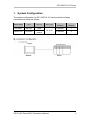
1. System Configuration
The system configuration for IEC 60870-5-101 devices and the display
connected are shown as follows.
Series Name
CPU
Link I/F
TELVENT
SM-CPU
COM
Selta STCE
CPU2000
COM A
COM B
SIO Type
RS-232C
Configuration
Example
Cable
Diagram
Example 1
1
Example 2
2
Display
Master
GP-Pro EX Device/PLC Connection Manual
Slave
3
IEC 60870-5-101 Driver
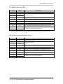
■ IPC COM Port
When connecting IPC with an External Device, the COM port used depends on the
series and SIO type. Please refer to the IPC manual for details.
Usable port
Series
Usable Port
RS-232C
RS-422/485(4 wire) RS-422/485(2 wire)
PS-2000B
COM1*1, COM2,
COM3*1, COM4
-
-
PS-3450A, PS-3451A,
PS3000-BA, PS3001-BD
COM1, COM2*1*2
COM2*1*2
COM2*1*2
PS-3650A (T41 model),
PS-3651A (T41 model)
COM1*1
-
-
PS-3650A (T42 model),
PS-3651A (T42 model)
COM1*1*2, COM2
COM1*1*2
COM1*1*2
PS-3700A (PentiumR4-M) COM1*1, COM2*1,
PS-3710A
COM3*2, COM4
COM3*2
COM3*2
PS-3711A
COM1*1, COM2*2
COM2*2
COM2*2
PS4000*3
COM1, COM2
-
COM1*1*2
*1*2
*1
PL3000
COM1 , COM2 ,
COM3, COM4
COM1*1*2
PE-4000B Atom N270
COM1, COM2
-
*4
PE-4000B Atom N2600
COM1, COM2
*4
COM3 , COM4 ,
COM5*4, COM6*4
COM3*4, COM4*4,
COM5*4, COM6*4
*1 The RI/5V can be switched. Use the IPC’s switch to change if necessary.
*2 Set up the SIO type with the DIP Switch. Please set up as follows according to SIO type to be
used.
*3 When making communication between an External Device and COM port on the Expansion
slot, only RS-232C is supported. However, ER (DTR/CTS) control cannot be executed because
of the specification of COM port.
For connection with External Device, use user-created cables and disable Pin Nos. 1, 4, 6 and 9.
Please refer to the IPC manual for details of pin layout.
*4 Set up the SIO type with the BIOS. Please refer to the IPC manual for details of BIOS.
GP-Pro EX Device/PLC Connection Manual
4
IEC 60870-5-101 Driver
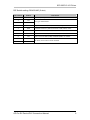
DIP Switch setting: RS-232C
DIP Switch
1
Setting
OFF
*1
Description
Reserved (always OFF)
2
OFF
3
OFF
4
OFF
Output mode of SD (TXD) data: Always output
5
OFF
Terminal resistance (220) insertion to SD (TXD): None
6
OFF
Terminal resistance (220) insertion to RD (RXD): None
7
OFF
Short-circuit of SDA (TXA) and RDA (RXA): Not available
8
OFF
Short-circuit of SDB (TXB) and RDB (RXB): Not available
9
OFF
10
OFF
SIO type: RS-232C
RS (RTS) Auto control mode: Disabled
*1 When using PS-3450A, PS-3451A, PS3000-BA and PS3001-BD, turn ON the set value.
DIP Switch setting: RS-422/485 (4 wire)
DIP Switch
Setting
Description
1
OFF
2
ON
3
ON
4
OFF
Output mode of SD (TXD) data: Always output
5
OFF
Terminal resistance (220) insertion to SD (TXD): None
6
OFF
Terminal resistance (220) insertion to RD (RXD): None
7
OFF
Short-circuit of SDA (TXA) and RDA (RXA): Not available
8
OFF
Short-circuit of SDB (TXB) and RDB (RXB): Not available
9
OFF
10
OFF
Reserved (always OFF)
SIO type: RS-422/485
RS (RTS) Auto control mode: Disabled
GP-Pro EX Device/PLC Connection Manual
5
IEC 60870-5-101 Driver
DIP Switch setting: RS-422/485 (2 wire)
DIP Switch
Setting
Description
1
OFF
2
ON
3
ON
4
OFF
Output mode of SD (TXD) data: Always output
5
OFF
Terminal resistance (220) insertion to SD (TXD): None
6
OFF
Terminal resistance (220) insertion to RD (RXD): None
7
ON
Short-circuit of SDA (TXA) and RDA (RXA): Available
8
ON
Short-circuit of SDB (TXB) and RDB (RXB): Available
9
ON
10
ON
Reserved (always OFF)
SIO type: RS-422/485
RS (RTS) Auto control mode: Enabled
GP-Pro EX Device/PLC Connection Manual
6
IEC 60870-5-101 Driver
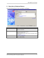
2. Selection of External Device
Select the External Device to be connected to the Display.
Setup Items
Manufacturer
Setup Description
Select the maker of the External Device to be connected.
Select "IEC Standard"
Series
Select a model (series) of the External Device to be
connected and connection method.
Select "IEC 60870-5-101".
Check the External Device which can be connected in system
configuration.
“System Configuration”
Select the Display port to be connected to the External
Device. (Select COM1)
Port
GP-Pro EX Device/PLC Connection Manual
7
IEC 60870-5-101 Driver
3. Example of Communication Setting
Examples of communication settings of the display and the external device
recommended by Pro-face are shown.
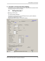
3.1.
Setting Example 1
■ Setting of GP-Pro EX
♦ Communication Settings
To display the setup screen, from the [Project] menu, point to [System
Settings] and select [Device/PLC].
Please select REE Profile for TELVENT devices.
GP-Pro EX Device/PLC Connection Manual
8
IEC 60870-5-101 Driver
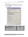
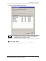
♦ Device Settings
To display the [Individual Device Settings] dialog box, from [DeviceSpecific Settings] in the [Device/PLC] window, select the external device
and click [Settings]
.
• Station Configuration
Please set the following configuration items as shown below.
Configuration items
Setting
Synchronize Display Unit Clock
ON
Synchronize After Initialization
ON
Command Transmission Method
Use Execute Termination
GP-Pro EX Device/PLC Connection Manual
Select /Execute
ON
9
IEC 60870-5-101 Driver
• Information Object Address Configuration
Please select REE profile for TELVENT devices.
■ External Device Settings
External Device settings vary depending on the device. Refer to your
External Device manual for details.
GP-Pro EX Device/PLC Connection Manual
10
IEC 60870-5-101 Driver
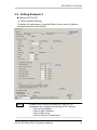
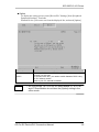
3.2. Setting Example 2
■ Setting of GP-Pro EX
♦ Communication Settings
To display the setup screen, from the [Project] menu, point to [System
Settings] and select [Device/PLC].
NOTE
• Please confirm that the following IEC 60870-5-101
parameters are configured according to PLC settings.
• Size of Link Address
• Size of ASDU Address
• Size of Object Info.
• Size of Cause of Transmission
GP-Pro EX Device/PLC Connection Manual
11
IEC 60870-5-101 Driver
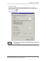
♦ Device Settings
To display the [Individual Device Settings] dialog box, from [DeviceSpecific Settings] in the [Device/PLC] window, select the external device
and click [Settings]
.
• Station Configuration
NOTE
• Please specify Command Transmission Method according to
PLC settings.
GP-Pro EX Device/PLC Connection Manual
12
IEC 60870-5-101 Driver
• Information Object Address Configuration
NOTE
• Please specify correct ranges of objects according to PLC
settings by selecting “Generic” profile.
■ External Device Settings
External Device settings vary depending on the device. Refer to your
External Device manual for details.
GP-Pro EX Device/PLC Connection Manual
13
IEC 60870-5-101 Driver
4. Setup Items
Setup the Display’s communication settings in GP-Pro EX or in Display’s
offline mode. The setting of each parameter must match that of the
External Device.
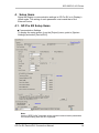
4.1. GP-Pro EX Setup Items
■ Communication Settings
To display the setup screen, from the [Project] menu, point to [System
Settings] and select [Device/PLC].
Note:
Use the “REE Profile” link to set all the required communication parameters
for communicating with SAITEL equipment.
GP-Pro EX Device/PLC Connection Manual
14
IEC 60870-5-101 Driver
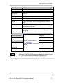
Setup Items
Description
SIO Type
Select “RS232”
Speed
Select the communication speed. (Set 19200 Kbps)
Data Length
Select “8”
Parity
Select “NONE”
Stop Bit
Select “1”
Flow Control
Select “NONE”
Timeout
Use an integer value from 1 to 127 to enter the time (second)
for which the Display waits for the response from External
Device.
Retry
In case of no response from the External Device, use an
integer from 0 to 255 to enter how many times the Display
retransmits the command.
Wait to Send
Use an integer from 0 to 255 to enter standby time (ms) for
the Display from receiving packets to transmitting next
commands.
IEC101 Related Parameters
Only “Unbalanced Mode” is
supported
Transmission Mode
Common Address of
ASDU
Frame Length
Size of Link Address
Size of ASDU Address
Please select according to
Fixed to 255.
REE Profile.
to set all the
[Click
values]
Size of Object
Information
Size of Cause of
Transmission
NOTE
• Refer to the GP-Pro EX Reference Manual for Indirect Device.
Cf. GP-Pro EX Reference Manual "Changing the
Device/PLC at Runtime (Indirect Device)"
GP-Pro EX Device/PLC Connection Manual
15
IEC 60870-5-101 Driver
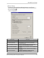
■ Device Settings
To display the [Individual Device Settings] dialog box, from [DeviceSpecific Settings] in the [Device/PLC] window, select the external device
and click [Settings]
.
• Station Configuration
Setup Items
Description
Link Address
Set the Slave station Link Address here.
Common Address of ASDU
Set the slave station Common Address of ASDU
Time Interval (in Minutes)
Set the frequency to send “Clock Synchronization
Command [CON 103]”
Synchronize Display Unit Clock
Check this to adjust the Display unit clock when PLC
sends time for Clock Synchronize command
Synchronize After Initialization
Set whether clock synchronization must be followed after
initialization
Command Transmission Method
Select Select / Execute or Direct Execute according to
PLC settings
Use Execute Termination
Set whether the target PLC transmits “Activation
Termination” after executing a command.
GP-Pro EX Device/PLC Connection Manual
16
IEC 60870-5-101 Driver
NOTE
• Please confirm that Link Address and Common Address of
ASDU are within range of the values.
• Information Object Address Configuration:
NOTE
• Please refer to External Device user manual for more details
about how to setup Link Address and other settings.
• When "REE" profile is selected, Address of object information
is fixed.
• When "Generic" profile is selected, address of object
information can be configured.
GP-Pro EX Device/PLC Connection Manual
17
IEC 60870-5-101 Driver
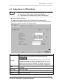
4.2. Setup Items in Offline Mode
NOTE
• Refer to the Maintenance/Troubleshooting guide for information
on how to enter offline mode or about the operation.
Cf. Maintenance/Troubleshooting Guide "Offline Mode"
■ Communication Settings
To display the setting screen, touch [Device/PLC Settings] from
[Peripheral Equipment Settings] in the off-line mode. Touch the External
Device you want to set from the displayed list.
Setup Items
Setup Descriptions
Select the SIO Type to communicate with External Device
SIO Type
To make the communication settings correctly, confirm the serial
interface specifications of Display unit for [SIO Type]. We cannot
guarantee the operation if a communication type that the serial
interface does not support is specified. For details concerning the
serial interface specifications, refer to the manual for Display unit.
Speed
Select the communication speed between the External Device and
the Display.
Data Length
Select data length.
Parity
Select how to check parity.
Stop Bit
Select a Stop bit length
GP-Pro EX Device/PLC Connection Manual
18
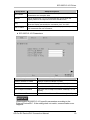
IEC 60870-5-101 Driver
Setup Items
Setup Descriptions
Flow Control
Select the communication control method to prevent overflow of
transmission and reception data.
Timeout
Use an integer from 1 to 127 to enter the time (s) for which the
Display waits for the response from the External Device.
Retry
In case of no response from the External Device, enter how many
times the Display retransmits the command, from "0 to 255".
Wait To Send
Enter the standby time (ms) from when the Display receives packets
until it transmits the next command,
♦ IEC 60870-5-101 Parameters:
Setup Items
Setup Descriptions
Common Address of ASDU
Displays Common Address of ASDU.
Size of Link Address
Select the Link Address Size. [1 or 2 Bytes]
Size of ASDU Address
Select the size of ASDU Address [1 or 2 Bytes]
Size of Object Information
Select the Size of Object Information address[1 or 2 or
3 Bytes]
Size of Cause of Transmission
Select the Size of Cause of Transmission [1 or 2 Bytes]
Please select IEC60870-5-101 specific parameters according to the
External Device/PLC. If the setting does not match, communication error
happens.
GP-Pro EX Device/PLC Connection Manual
19
IEC 60870-5-101 Driver
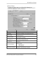
■ Device Settings
To display the setting screen, touch [Device/PLC Settings] from
[Peripheral Equipment Settings]. Touch the External Device you want to
set from the displayed list, and touch [Device].
Setup Items
Setup Descriptions
Profile
Displays selected profile.
Link Address
Select the Link Address of the External Device/PLC
Common ASDU
Address Select the Common ASDU Address of the
External Device/PLC
Clock Sync.Interval
Select the Time Interval (in minutes) to send Clock
Synchronization command.
Sync. Display unit
Clock Select to adjust Display unit clock when Time data
received from External Device/PLC.
Sync. After Init.
Set whether clock synchronization must be followed after
initialization
Transmission Method
Set the command transmission sequence to use from the
following options.
• Select /Execute
• Direct Execute
Use Execute Termination
Set whether the target PLC transmits “Activation
Termination” after executing a command.
GP-Pro EX Device/PLC Connection Manual
20
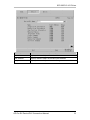
IEC 60870-5-101 Driver
Setup Items
Setup Descriptions
Name
Displays Address Object Information Name
Start Address
Displays Address Object Information Start Address
Range
Displays Address Object Information Range.
GP-Pro EX Device/PLC Connection Manual
21
IEC 60870-5-101 Driver
■ Option
To display the setting screen, touch [Device/PLC Settings] from [Peripheral
Equipment Settings]. Touch the
External Device you want to set from the displayed list, and touch [Option].
Setup Items
RI/VCC
NOTE
Setup Descriptions
You can switch between RI/VCC on the 9th pin when you select
RS-232C for SIO type.
To connect to the IPC, you need to switch between RI/5V using
the IPC selector switch.
Refer to your IPC manual for details.
• GP-4100 series, GP-4*01TM, GP-Rear Module, LT-4*01TM
and LT-Rear Module do not have the [Option] setting in the
offline mode.
GP-Pro EX Device/PLC Connection Manual
22
IEC 60870-5-101 Driver
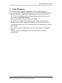
5. Cable Diagrams
The following cable diagrams may be different from cable diagrams
recommended by External Device Manufacturer. Please be assured there is no
operational problem in applying the cable diagrams shown in this manual.
• The FG pin of the External Device body must be grounded according to
your country’s applicable standard.
Refer to your External Device manual for details.
• SG and FG are connected inside the Display. When connecting the
External Device to SG, design your system to avoid short-circuit loops.
• Connect an isolation unit if the communication is not stable due to noise or
other factors.
• The connector type or signal name may vary depending on the External
Device.
Connect correctly corresponding to the External Device interface
specifications.
GP-Pro EX Device/PLC Connection Manual
23
IEC 60870-5-101 Driver
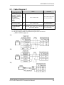
5.1. Cable Diagram 1
Display
(Connection Port)
GP3000 (COM1)
GP4000*1 (COM1)
SP5000 (COM1/2)
ST (COM1)
LT3000 (COM1)
IPC*2
PC/AT
Cable
Remarks
1A
User created cable
The cable length must
be 15m maximum.
GP-4105 (COM1)
1B
User created cable
The cable length must
be 15m maximum.
LT-4*01TM (COM1)
LT-Rear Module
(COM1)
1C
RJ45 RS-232C Cable (5m) by Pro-face The cable length must
PFXZLMCBRJR21
be 5m maximum.
*1 All GP4000 models except GP-4100 series and GP-4203T
*2 Only the COM port which can communicate by RS-232C can be used.
■IPC COM Port (page 4)
1A)
1B)
1C)
GP-Pro EX Device/PLC Connection Manual
24
IEC 60870-5-101 Driver
5.2. Cable Diagram 2
Display
(Connection Port)
GP3000 (COM1)
GP4000*1 (COM1)
SP5000 (COM1/2)
ST (COM1)
LT3000 (COM1)
IPC*2
PC/AT
Cable
Remarks
2A
User created cable
The cable length must
be 15m maximum.
GP-4105 (COM1)
2B
User created cable
The cable length must
be 15m maximum.
LT-4*01TM (COM1)
LT-Rear Module
(COM1)
2C
RJ45 RS-232C Cable (5m) by Pro-face The cable length must
PFXZLMCBRJR21
be 5m maximum.
*1 All GP4000 models except GP-4100 series and GP-4203T
*2 Only the COM port which can communicate by RS-232C can be used.
■IPC COM Port (page 4)
2A)
2B)
2C)
GP-Pro EX Device/PLC Connection Manual
25
IEC 60870-5-101 Driver
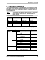
6. Supported Device Address
The following table shows the range of supported device addresses. Please
note that the actual supported range of the devices varies depending on the
External Device to be used. Please check the actual range in the manual of
your External Device.
NOTE
• When use any address range, set the [Generic] in [Information
Object Address Configuration] tab - [profile] of [Individual
Device Settings].
Device
Name
SP
DP
ME
SC
IT
ST
SE
DC
RC
Description
Range
Single Point Information
Double-Point Information
Measured Value
Single Command
Integrated Totals
Step Position Information
Set Point Command
Double Command
Regulating Step Command
1000 ~ 10999
11000 ~ 12999
13000 ~ 14999
15000 ~ 16999
17000 ~ 18999
19000 ~ 20999
21000 ~ 22999
23000 ~ 24999
25000 ~ 26999
Note
Read only
Read only
Read only
Write only
Read only
Read only
Write only
Write only
Write only
Each device consists of several sub category and elements. The following
table lists the sub category and elements for each Device group
Device
Name
Sub Category / Element
Category
Element
SPI
BL
SIQ
SB
NT
SP
IV
TIME
DP
DIQ
IV
SU
MSEC
MIN
HOUR
DAY
MONTH
YEAR
BL
SB
NT
IV
DPI
Description
Single Point Information
0: OFF
1: ON
0: Not Blocked
1: Blocked
0: Not Substituted
1: Substituted
0: Topical
1: Not Topical
0: Valid
1: Invalid
Valid
Summer Time
Milliseconds
Minute
Hour
Day
Month
Year
Blocked / Not Blocked
Substituted / Not Substituted
Topical / Not Topical
Valid / Invalid
Double Point Information
GP-Pro EX Device/PLC Connection Manual
Note
*1
*1
*1
*1
*1
*1
*1
*2
*2
*2
*2
*2
*2
*1
*1
*1
*1
*2
26
IEC 60870-5-101 Driver
Device
Name
DP
ST
ME
Sub Category / Element
Category
Element
IV
SU
MSEC
MIN
TIME
HOUR
DAY
MONTH
YEAR
T
VTI
VAL
OV
BL
QDS
SB
NT
IV
IV
SU
MSEC
MIN
TIME
HOUR
DAY
MONTH
YEAR
OV
BL
SB
QDS
NT
IV
VA
VAL
IV
SU
MSEC
MIN
TIME
HOUR
DAY
MONTH
YEAR
VAL
SQ
BCR
CY
CA
SC
DC
SCO
DCO
IV
IV
SU
MSEC
MIN
HOUR
DAY
MONTH
YEAR
SCS
DCS
RC
RCO
RCS
SE
VA
VAL
IT
TIME
Description
Valid
Summer Time
Milliseconds
Minute
Hour
Day
Month
Year
Transient
Value
Overflow / No Overflow
Blocked / Not Blocked
Substituted / Not Substituted
Topical / Not Topical
Valid / Invalid
Valid
Summer Time
Milliseconds
Minute
Hour
Day
Month
Year
Overflow / No Overflow
Blocked / Not Blocked
Substituted / Not Substituted
Topical / Not Topical
Valid / Invalid
Measured Value
Valid
Summer Time
Milliseconds
Minute
Hour
Day
Month
Year
Counter value
Sequence
(Carry) Counter Overflow / No
Overflow
Counter Adjusted / Not
Adjusted
Counter value Valid / Invalid
Valid
Summer Time
Milliseconds
Minute
Hour
Day
Month
Year
Single command state
Double command state
Regulating step command
state
Value (Normalized / Scaled /
short floating point)
Note
*1
*1
*2
*2
*2
*2
*2
*2
*1
*2
*1
*1
*1
*1
*1
*1
*1
*2
*2
*2
*2
*2
*2
*1
*1
*1
*1
*1
*2
*1
*1
*2
*2
*2
*2
*2
*2
*2
*2
*1
*1
*1
*1
*1
*2
*2
*2
*2
*2
*2
*1
*2
*2
*2
*1 Bit Address Only
*2 Word Address Only
GP-Pro EX Device/PLC Connection Manual
27
IEC 60870-5-101 Driver
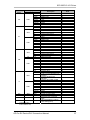
7. Error Messages
Error messages are displayed on the screen of the Display as follows: “No. :
Device Name: Error Message (Error Occurrence Area).
Each description is shown below.
Item
No.
Device Name
Error Message
Error occurrence
Area
Description
Error number
Name of the external device where an error has occurred.
Device /PLC name is the title of the External Device set
with GP-Pro EX (Initial value [PLC1])
Displays messages related to an error that has occurred
Displays the device address of the External device where
an error has occurred or error codes received from the
External Device.
Error Messages specific to the External Device
Error No
Error Message
Description
RHxx128
(Node Name): NACK: message
not accepted. Link busy
PLC sends NACK for Displays request.
RHxx129
(Node Name): Link service not
functioning
PLC replied this for Display request in
Control byte [Function Code]
RHxx130
(Node Name): Link service not
implemented
PLC replied this for Display request in
Control byte [Function Code]
RHxx131
Configured object information
range is too large. Please reduce
the range
Insufficient memory to allocate the specified
device address ranges.
RHxx132
(Node Name): Command
confirmation timed out.
PLC does not reply to commands.
Please check communication settings.
RHxx133
(Node Name):Initialization
procedure timed out.
PLC does not respond to interrogation
command.
Please check communication settings.
GP-Pro EX Device/PLC Connection Manual
28
IEC 60870-5-101 Driver
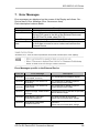
8. Interoperability list
8.1. Network configuration
□ Point-to-point
□ Multiple point to point
□ Redundant lines
■ Multi-point-party line
□ Multi point star
8.2. Physical layer
Transmission speed (control direction)
Unbalanced
Unbalanced interface
interchange circuit
circuit V.24/V.28
V.24/V.28
Recommended if >
standard
1200 bit/s
□ 100 bit/s
□ 200 bit/s
□ 300 bit/s
□ 600 bit/s
□ 1200 bit/s
■ 2400 bit/s
■ 4800 bit/s
■ 9600 bit/s
■ 19200 bit/s*
Balanced interchange circuit X.24/X.27
□ 2400 bit/s
□ 4800 bit/s
□ 9600 bit/s
□ 19200 bit/s
□ 38400 bit/s
□ 56000 bit/s
□ 4000 bit/s
* not defined in 870-5-101
Transmission speed (monitor direction)
Unbalanced
Unbalanced interface
interchange circuit
circuit V.24/V.28
V.24/V.28
Recommended if >
standard
1200 bit/s
□ 100 bit/s
□ 200 bit/s
□ 300 bit/s
□ 600 bit/s
□ 1200 bit/s
■ 2400 bit/s
■ 4800 bit/s
■ 9600 bit/s
■ 19200 bit/s*
Balanced interchange circuit X.24/X.27
□ 2400 bit/s
□ 4800 bit/s
□ 9600 bit/s
□ 19200 bit/s
□ 38400 bit/s
□ 56000 bit/s
□ 4000 bit/s
* not defined in 870-5-101
GP-Pro EX Device/PLC Connection Manual
29
IEC 60870-5-101 Driver
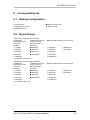
8.3. Link layer
Frame format FT1.2, single character 1 and the fixed timeout interval are used exclusively in
this companion standard.
Link transmission
Address field of the link
□ Balanced transmission
■ Unbalanced transmission
□ Not present (balanced only)
■ One octet
■ Two octets
□ Structured
■ Unstructured
Frame length
255 Maximum length L (number of octets)
8.4. Application layer
Common address of ASDU
■ One octet
■ Two octets
Information object address
■ One octet
■ Two octets
■ Three octets
■ Structured
□ Unstructured
Cause of transmission
■ One octet
■ Two octets (with originator address)
GP-Pro EX Device/PLC Connection Manual
30
IEC 60870-5-101 Driver
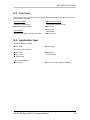
8.5. ASDUs
Process information in monitor direction
Short name
■ <1> := Single-point information
□ <2> := Single-point information with time tag
■ <3> := Double-point information
□ <4> := Double-point information with time tag
■ <5> := Step position information
□ <6> := Step position information with time tag
□ <7> := Bitstring of 32 bit
□ <8> := Bitstring of 32 bit with time tag
□ <9> := Measured value, normalized value
□ <10> := Measured value, normalized value with time tag
■ <11> := Measured value, scaled value
□ <12> := Measured value, scaled value with time tag
□ <13> := Measured value, short floating point value
□ <14> := Measured value, short floating point value with time tag
■ <15> := Integrated totals
□ <16> := Integrated totals with time tag
□ <17> := Event of protection equipment with time tag
□ <18> := Packed start events of protection equipment with time tag
□ <19> := Packed output circuit information of protection equipment with time
M_SP_NA_1
M_SP_TA_1
M_DP_NA_1
M_DP_TA_1
M_ST_NA_1
M_ST_TA_1
M_BO_NA_1
M_BO_TA_1
M_ME_NA_1
M_ME_TA_1
M_ME_NB_1
M_ME_TB_1
M_ME_NC_1
M_ME_TC_1
M_IT_NA_1
M_IT_TA_1
M_EP_TA_1
M_EP_TB_1
M_EP_TC_1
tag
□ <20> := Packed single-point information with status change detection
□ <21> := Measured value, normalized value without quality descriptor
■ <30> := Single-point information with time tag CP56Time2a
■ <31> := Double-point information with time tag CP56Time2a
■ <32> := Step position information with time tag CP56Time2a
□ <33> := Bitstring of 32 bit with time tag CP56Time2a
□ <34> := Measured value, normalized value with time tag CP56Time2a
□ <35> := Measured value, scaled value with time tag CP56Time2a
□ <36> := Measured value, short floating point value with time tag
M_PS_NA_1
M_ME_ND_1
M_SP_TB_1
M_DP_TB_1
M_ST_TB_1
M_BO_TB_1
M_ME_TD_1
M_ME_TE_1
M_ME_TF_1
CP56Time2a
□ <37> := Integrated totals with time tag CP56Time2a
□ <38> := Event of protection equipment with time tag CP56Time2a
□ <39> := Packed start events of protection equipment with time tag
M_IT_TB_1
M_EP_TD_1
M_EP_TE_1
CP56Time2a
□ <40> := Packed output circuit information of protection equipment with time
M_EP_TF_1
tag CP56Time2a
GP-Pro EX Device/PLC Connection Manual
31
IEC 60870-5-101 Driver
Process information in control direction
■ <45> := Single command
■ <46> := Double command
■ <47> := Regulating step command
■ <48> := Set point command, normalized value
□ <49> := Set point command, scaled value
□ <50> := Set point command, short floating point value
□ <51> := Bitstring of 32 bit
C_SC_NA_1
C_DC_NA_1
C_RC_NA_1
C_SE_NA_1
C_SE_NB_1
C_SE_NC_1
C_BO_NA_1
System information in monitor direction
□ <70> := End of initialization
M_EI_NA_1
System information in control direction
□ <100>:= Interrogation command
□ <101>:= Counter interrogation command
□ <102>:= Read command
□ <103>:= Clock synchronization command
□ <104>:= Test command
□ <105>:= Reset process command
□ <106>:= Delay acquisition command
□ <107>:= Test command with time tag CP56Time2a
C_IC_NA_1
C_CI_NA_1
C_RD_NA_1
C_CS_NA_1
C_TS_NA_1
C_RP_NA_1
C_CD_NA_1
C_TS_TA_1
Parameter in control direction
□ <110>:= Parameter of measured value, normalized value
□ <111>:= Parameter of measured value, scaled value
□ <112>:= Parameter of measured value, short floating point value
□ <113>:= Parameter activation
P_ME_NA_1
P_ME_NB_1
P_ME_NC_1
P_AC_NA_1
File transfer
□ <120>:= File ready
□ <121>:= Section ready
□ <122>:= Call directory, select file, call file, call section
□ <123>:= Last section, last segment
□ <124>:= Ack file, ack section
□ <125>:= Segment
□ <126>:= Directory {blank or X, only available in monitor (standard)
F_FR_NA_1
F_SR_NA_1
F_SC_NA_1
F_LS_NA_1
F_AF_NA_1
F_SG_NA_1
F_DR_TA_1
direction}
GP-Pro EX Device/PLC Connection Manual
32
IEC 60870-5-101 Driver
8.6. Basic application functions
Station initialization
■ Remote initialization
Cyclic data transmission
□ Cyclic data transmission
Read procedure
□ Read procedure
General interrogation
■ Global
Clock synchronization
□ Global
Command transmission
□ Direct command transmission
□ Direct set point transmission
■ Select and execute command
■ Select and execute set point
□ C_SE ACTTERM used
■ No additional definition
□ Short pulse duration (duration determined by a system parameter)
□ Long pulse duration (duration determined by a system parameter)
□ Persistent output
Transmission of integrated totals
□ Counter request
□ Counter freeze without reset
□ Counter freeze with reset
□ General request counter
Parameter loading
□ Threshold value
□ Smoothing factor
□ Low limit for transmission of measured value
□ High limit for transmission of measured
Parameter activation
□ Act/deact of persistent cyclic or periodic transmission of the addressed object
Test procedure
□ Test procedure
GP-Pro EX Device/PLC Connection Manual
33
IEC 60870-5-101 Driver
File transfer
File transfer in monitor direction
□ Transparent file
□ Transmission of disturbance data of protection equipment
□ Transmission of sequences of events
□ Transmission of sequences of recorded analogue values
File transfer in control direction
□ Transparent file
Background scan
□ Background scan
Acquisition of transmission delay
□ Acquisition of transmission delay
GP-Pro EX Device/PLC Connection Manual
34