1
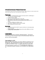
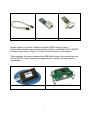
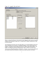
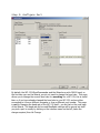
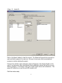
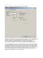
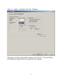
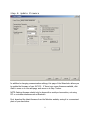
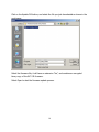
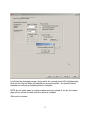
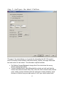
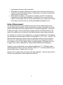
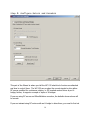
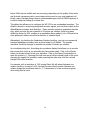
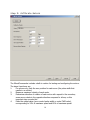
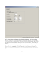
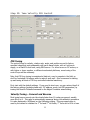
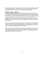
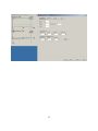
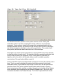
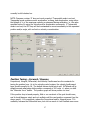
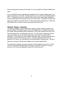
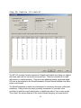
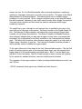
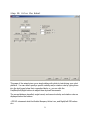
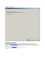
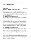
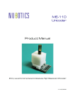
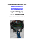
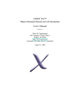
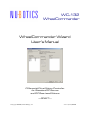
WC-132 WheelCommander WheelCommander Wizard User’s Manual Differential Drive Motion Controller for Standard RC Servos and DC Gearhead Motors ---DRAFT--Copyright 2009, Noetic Design, Inc. 1.01 3/10/2009 WheelCommander Wizard Overview This program helps owners of the Nubotics WC-132 WheelCommander differential drive controller set it up for use with their mobile robot. Features Connects to a WheelCommander using any serial port (built-in or USB dongle) or I2C dongles from TotalPhase or Diolan Provides a firmware updater Helps you enter physical dimensions of your robot Offers display of current status of unit, including supply voltages Helps you enter encoder and motor parameters, for either RC servos or DC motors Coordinates calibration and displays results Gives access to EEPROM constants directly if needed Offers interactive PID loop tuning tools Benefits Eliminates the need for the WC-132 owner to write their own throw-away setup code for the board Provides method for tuning PID parameters that would be difficult to do via an embedded master robot controller Description Thank you for purchasing a Nubotics WheelCommander. This manual should help you find your way through the WheelCommander Wizard and get your robot running quickly. Connecting to a PC Before you can use the Wizard, you need a method to connect it to your Windows PC. We recommend the Acroname 4 pin extension cable, p/n C10-SER-INT-CONN-EXT (figure 1), together with either the Acroname USB Serial Interface Connector, p/n S22-USB-SERIAL-INT-CONN (figure 2), or the Serial Interface Connector, p/n S13-SERIAL-INT-CONN (figure 3). 2 Figure 1: Extension Cable Figure 2: USB Connector Figure 3: Serial Connector Another option is to use the TotalPhase Aardvark USB/I2C dongle, figure 4 (http://www.totalphase.com/products/aardvark_i2cspi/), or the Diolan U2C-12 USB/I2C interface board, shown in figure 5. Drivers for both are built in to the Wizard. These products, while more expensive than USB/Serial dongles, also provide their own I2C and SPI GUI control programs and signal monitors, and can be quite useful for robot builders. Figure 4: TotalPhase Aardvark Figure 5: Diolan U2C-12 3 Step 1: Launch the Wizard When you launch the Wizard, it will quickly find and display all valid serial ports and I2C dongles in the Connections Found: box – be they your PC’s built-in serial ports or USB to serial interfaces. The checkboxes to the left of the port names allow you to control whether a given port will be searched for the presence of a WheelCommander or other Noetic Design, Inc. product. A greyed-out check means skip this port; a black check means search it. By default, the Wizard will search all detected ports, which is useful if you don’t know which port your WheelCommander is attached to. However, once you know which port, you should uncheck the other ports to speed up the search process in the future. 4 Step 2: Configure Port By default, the WC-132 WheelCommander and the Wizard are set to 38400 baud, so the first time you run the Wizard, you do not need to change the baud rate. This page allows you to change the current baud rate for searching for a WC-132; this is useful later on if you have already changed the baud rate in your WC-132, and are either connecting to it from a different computer or from a different port number. This page is not for changing the baud rate of the WC-132 itself – you do that on the next page of the Wizard. The baud rate list box and BlueRadio settings will be greyed out until you pick a port to modify by clicking on the interface name on the left; make the change required, then hit Change. 5 Step 3: Search Click on the Search button to start the search. The Wizard will spend a few seconds on each port before going to the next one. Be sure to have your robot connected and powered on before starting the search. If found, the interface name and device name will appear in the Search Results on the right; if you have more than one Nubotics device attached, uncheck all but the one you wish to configure. If not found, check your robot’s power source and connections. The green LED should be on and the red LED should be off. Click Next when ready. 6 Step 4: Change Communications Settings This page of the wizard lets you modify the Wizard’s and the WC-132’s communications settings, if required. You can change the I2C slave address, the serial baud rate, enable or disable use of a BlueRadio Bluetooth interface, or select special communications settings to make the WC-132 compatible with certain controllers. If using a BasicStamp to control the WheelCommander, check on the Inter-char delay; this makes the WheelCommander slow down the character-to-character timing so the BasicStamp can keep up. If using a Savage Innovation’s OOPIC in I2C mode, check on Short Cmd Mode; this reduces the amount of data returned by each command. The Notify Motion Complete checkbox enables (in serial port mode only) asynchronous reporting of the completion of a motion command. 7 Step 5: Apply Communications Changes Click Apply to send the communications changes to the WC-132. The Current Status should change to indicate that the connection has been updated. 8 Step 6: Update Firmware In addition to changing communication settings, this page of the Wizard also allows you to update the firmware of your WC-132. If there is no newer firmware available, click Next to move on to the next page, and move on to Step 7 below. NOTE: flashing firmware should only be done with a serial port connection, not using I2C or a wireless interface such as Bluetooth. First, download the latest firmware from the Nubotics website, saving it in a convenient place of your hard drive. 9 Click on the Update FW button; and select the file you just downloaded as shown in the next image. Select the firmware file; it will have an extension “bin”, and contains an encrypted binary copy of the WC-132 firmware. Select Open to start the firmware update process. 10 It will start the download process, during which the red and green LEDs will alternately blink and the Current Status will indicate the percent complete. An Upload Finished message box will pop up indicating that it is complete. NOTE: do not switch away to another window during an upload; if you do, the wizard page will not refresh correctly until the upload is complete. Click next to continue. 11 Step 7: Configure the Robot Platform This page of the wizard allows you to specify the information the WC-132 needs to know to correctly convert between real-world velocity, position, and angle values and low level control of each wheel. The information required includes: Flip Platform Forward/Backward; change this if the robot drives the wrong direction during later testing Counter-Rotating Shafts; most differential drive robots are built such that the motors face away from each other; thus, when the robot moves forward, the left motor rotates counter-clockwise while the right motor rotates clockwise; check this box on if this is how your robot works, or off if your robot’s motors both 12 point towards the same side of the robot Wheel Base; the distance between the contact points of the two wheels; this is needed to convert the desired angle or rotation rate of the base to forward and reverse motion of each wheel Wheel Radius, Diameter, or Circumference; likewise, the WC-132 needs this information to convert desired distance or velocity into the correct amount of rotation of each wheel; this part of the wizard allows you to change any of these three values, and the other two will be automatically calculated for you Units of Measurement The WheelCommander does not need to know what units of measurement you are using to specify the wheel base, wheel circumference, velocity, and position; they just need to be consistent and use numerical values of reasonable magnitude – they must fit within two bytes, but also should offer enough precision that determination of the angle of the platform can be done with the desired precision using integer arithmetic. For example, for a wheel 8" in circumference, you could use multiples of 0.01" because the circumference would need two bytes to be specified (8 / 0.01 = 800 = 0x0320). On the other hand, using whole inches is also not desirable, as there can be as much as 0.5" in error on each measurement, which would result in very inaccurate odometry (0.5" distance error for every wheel rotation, or approximately a 14 degree error on a 90 degree turn, which is equivalent to only about 26 positions per 360 degrees). Instead, for many small robots, we recommend multiples of 0.1". With that, typical robot dimensions fit well in one byte, and also result in 0.1" or better position error per wheel rotation and a 1.4 degree error on turns. Another unit of measurement that works well is the millimeter. A typical robot wheel is 209 mm in circumference, with a wheel base of 89 mm. 13 Step 8: Configure Motors and Encoders This part of the Wizard is where you tell the WC-132 what kind of motors are attached and how to control them. The WC-132 can produce the correct signals to drive either RC servos modified for continuous rotation, or DC brushed motors driven by an Hbridge; further, it supports a couple of styles of H-bridges. If you are using RC servos and WheelWatcher encoders, the defaults shown above will be correct. If you are instead using DC motors with an H-bridge to drive them, you need to find out 14 a couple of things first: 1. what control signals do the H-bridges offer to control speed and direction of rotation? 2. what control signals can the WC-132 generate? 3. what additional circuitry, if any, are needed to connect the two together? 4. what is the best PWM frequency for my application? The WC-132 was designed to support the control signals for many common commercially available H-bridges, such as the Texas Instruments SN754410 dual motor H-bridge chip or its predecessor, the L293; the L298; or the ST VNH2SP30 or VNH3SP30 (used in Pololu’s various high current motor drivers). Note that these specific H-bridges require mode 2 below – two direction control signals. And, this list is not complete – many others should work too, when properly connected. The WC-132 can generate these combinations of signals for each motor: 1. sign/magnitude 1: a single unsigned magnitude PWM signal and a single direction control signal 2. sign/magnitude 2: a single unsigned magnitude PWM signal and two direction control signals (one the inverse of the other) 3. locked antiphase 1: a single signed magnitude PWM signal and an active high enable line 4. locked antiphase 2: a single signed magnitude PWM signal and an active low enable line An unsigned magnitude PWM signal means that a 0% duty cycle corresponds to 0 speed, or no output, and 100% duty cycle corresponds to full speed; intermediate values result in intermediate speeds. A signed magnitude PWM signal, generated for cases 3 and 4 above, is used for lockedantiphase motor control rather than sign-magnitude control. In locked-antiphase, the PWM signal is at 50% duty cycle for 0 speed; values between 0% and 50% for speed in one direction; and values from 50% to 100% for speeds in the other direction, with 0% and 100% being maximum speeds in the opposite directions. Locked anti-phase can work well for certain kinds of motors, but not all motors; motors with very low impedance are more efficiently driven using sign/magnitude mode; this includes many low cost hobbyist quality DC motors. The choice of PWM frequency depends on a lot of variables. Often, experimentation is the best way to find the right frequency. A good starting point is around 1KHz. Lower frequencies may result in large current spikes, shortening the life of the motor brushes, which is not desired; higher frequencies can result in lower efficiency. Frequencies 15 below 16KHz can be audible and very annoying, depending on the quality of the motor and its audio resonance points; some cheap motors work as very good speakers too! Finally, many H-bridge designs have a recommended upper limit on PWM frequency; it is wise to keep the setting at or below this. This dialog also allows you to configure the WC-132 to use nonstandard encoders. The default is meant to accept sign/magnitude encoder signals, such as those output by the WheelWatcher encoders from Nubotics. These encoders include a quadrature decoder chip, which converts the two channels of 32 stripes per rotation (which are phase shifted by design by 90% resulting in a quadrature timing pattern), into 128 active low clock pulses per rotation as well as a direction of rotation signal. Alternatively, by checking the Quadrature Signals check box, you can use commercial industrial quadrature encoders such as those made by US Digital. The encoder resolution should be changed to indicate the number of stripes per rotation. As a troubleshooting tool, this dialog also provides a display that allows you to monitor the encoder tick count as you manually spin the encoder shaft. Click on the Monitor button (as shown below) to test your encoders. Click on the Reset Counts button to reset the counts to 0. Spinning the shaft one way a full turn should result in the count changing by roughly the resolution value; spinning the other way a full turn should change it the other direction. For example, with a resolution of 128, turning Robot A’s left wheel clockwise one rotation results in a count of +129; turning the same wheel counter clockwise one rotation brings the count back down to -1. Inaccuracies of a few counts are typical when doing this by hand. 16 17 Step 9: Calibrate Motors The WheelCommander includes a built-in routine for testing and configuring the motors. The steps it performs are: 1. For servos only, finds the zero position for each servo (the pulse width that results in no motion) 2. Measures maximum velocity of each motor 3. Determines direction of rotation of each motor with respect to the encoders; some servos rotate in the opposite direction compared to others, so this important step corrects this 4. Finds the output value (servo control pulse width or motor PWM value) corresponding to 10% of maximum speed and 80% of maximum speed 18 5. 6. Calculates the coefficients of a linear equation for each wheel (the m and b terms of y = mx + b, where y is speed measured by the encoders, and x is servo pulse width or PWM value) used to enable the WheelCommander to smoothly control velocity over a large useful range; b ensures that starting friction and the servo’s deadband is overcome even at low velocities, and m essentially sets the largest minimum output value needed to attain full speed Stores the measurements in EEPROM for use in the future If your robot uses DC motors with an external H-bridge instead of servos, we still recommend running calibration to determine motor rotation direction, maximum speed, and m and b values. In this case, step 1 is automatically skipped. While the factory default values for the servo zero positions, maximum speed, and m and b may function as is out of the box, it is highly recommended that you run the calibration procedure prior to tuning the PID loop parameters. TIP: Place the robot on a small box or stand, and run the calibration with the wheels off the ground. To calibrate, hit the Start button, then wait while the calibration routine runs. 19 NOTE: Do not change the Reverse Motor Direction checkboxes. The Reverse Motor Direction checkboxes are set automatically as result of the calibration procedure; there is no need normally to change them. The same is true for the other fields. We provide the ability to hand-modify these values just in case you ever need to, but normally you do not. When calibration is complete, hit Next. The values found during calibration will be stored in on board EEPROM, so your WC-132 will remember them even with the power off. 20 Step 10: Make Custom Settings Changes This dialog is provided just in case you ever need to modify the WheelCommander’s EEPROM constants directly. Normally, you should rely on the various pages of this configuration wizard to set the constants for you in a more controlled manner. 21 Step 11: Tune Velocity PID Control PID Tuning The control loops for velocity, rotation rate, angle, and position are set to factory specified values that work adequately with servo-based robots, with a 6 volt servo supply, on a MarkIII robot base, using GWS servos. For other servos or DC motors, or with higher or lower supplies, or different mechanical platforms, some tuning of the control loops will be necessary. Note, that PID loop tuning is considered a black art, even by experts in the field, so don’t be frustrated if it takes a while to make it work well – this is common for setting up and tuning all kinds of PID loop controlled industrial machinery. First, start with the default settings. If you need to start over, you can restore the all of the factory settings (including baud rate, I2C address, mode, and PID parameters) by issuing the Reset to Defaults command on the Adjust Constants wizard dialog. Velocity Tuning – Forward and Reverse Most typical servos cannot spin the wheels faster than 10 inches per second; usually more like 6 to 8. This value is automatically measured during the calibration procedure. It is also displayed in WCWizard on the Calibration dialog. This max speed value is used by the wizard to initialize the 1st Vel and 2nd Vel fields; 1st Vel is set to 80% of max 22 speed and 2nd Vel is set to 20% of max speed, as recommended values to use for tuning. Set your robot up on a small box (like a car up on jacks) so that the wheels can turn but the robot does not move. Click on the 1st Vel/Rot button and watch the graphs (you may need to move the main window to the right to fully uncover the graphs). First, we need to adjust the Feed Forward term to get the overall velocity to roughly match the requested velocity. The calibration procedure should have already set the slope and intercept values (m and b) to ensure that a Feed Forward value of 16 results in an accurate velocity value. But, if the velocity is too low, you need to increase Feed Forward; if it is too high, decrease it. If the velocity is very unstable, then reduce the two integral gains until it is stable. Reduce the proportional gains too if the integral gains are zero and it is still not stable. Now, try running it at the lower velocity by clicking on the 2nd Vel/Rot button. This will most likely be unstable – the velocity will rise and fall quickly, and not appear to be under control. This can be a result of a number of factors, usually that one or more of the constants is too large. You can try reducing each of these values until it is stable. If all else fails, you can start from scratch rather than work from the default values. First, set all constants to zero, and Feed Forward to 16. Tune just the Velocity Parameters and leave the Differential Drive (Steering) parameters at zero. Adjust Feed Forward until a smooth wheel velocity at or below the desired velocity is produced. The point of Feed Forward is to set a starting point for the control loops that is in the ballpark of the goal velocity under normal loads; it effectively bypasses the PID controller and feeds a speed request straight to the motors. This frees the PID loop to only control for error in velocity due to voltage drop, friction, or variable loads, without also having to provide all the output required to just move at all. Continuing with the tuning, increase the Proportional term slowly, until velocity control becomes unstable. Drop it back to be just on the edge. Next, increase the Integral term. This will usually take any sag out of the velocity to be at or very close to the goal velocity. Increase this until unstable, then drop it a back to the edge. Do the same with the Differential term. You should now have good control at low speeds. Verify the scalability by increasing the goal velocity by small steps – e.g., increments of 10. If the tuning is good, and the scale is good, it should continue to match the goal velocity up to Vmax. 23 As a final test, click on the Alternate button. Every Step Cycle Time number of seconds, it will switch between the 1st and 2nd velocity and rotation rate settings. Watch the graphs and fine tune the control loops to get nice looking, stable graphs. Velocity Tuning – Steering The steering velocity Proportional constant, steering velocity Integral constant, and steering velocity Differential constant are used to tune the ability of your robot to drive in a straight line. Often, the Proportional constant can be zero. The Integral constant should be nonzero but not too large, or the platform will overcompensate and not drive straight, and/or become unstable. With these settings, the steering velocity loop essentially uses a difference in position of each wheel as the error term – if one wheel gets ahead of the other, it’s velocity controller is told to slow down while the other is told to speed up. To tune the steering, watch the rotation rate and/or current angle in the bottom graph. These should remain near zero during a long move. If the angle grows continuously during a move, try increasing the Proportional and/or the Integral terms – but not too much, or it will become unstable and not track straight. NOTE: running the robot at top speed can result in poor tracking (straightness), as the control systems can become saturated. Try running 5-10% below Vmax. The image below shows typical graphs for a small robot using RC servos, with the steering not properly tuned, resulting in an angular drift. 24 25 Step 12: Tune Position PID Control The WheelCommander’s position control system uses the current velocity and acceleration values to produce a trapezoidal velocity profile over a commanded movement. During a move, velocity will increase at a constant acceleration to the specified maximum velocity; will continue at that velocity until it is time to decelerate; and will then decelerate smoothly to a stop at the goal position. The position itself, when plotted, will describe what’s referred to as an S-curve shape. This trajectory is used to set the goal position, to which the PID control loop attempts to slew the position of each wheel. It is important that the requested acceleration and velocity limits are within the capabilities of your robot platform; otherwise, the trajectory will not be able to be followed, and can result in unstable operation – overshooting of the goal and oscillation around it. Tuning of the PID control loop follows similar concepts as for tuning the velocity control loops. First, you need to stimulate the system by setting maximum velocity and acceleration values, a goal distance and/or angle to move over, and an optional loop time (Step Cycle Time) and an optional second position and/or angle to move to. These moves can be either absolute or relative, depending on the state of the Relative Moves checkbox (this corresponds to the difference between the D, W, and X, and Z commands described in the Product Manual). The Follow Trapezoidal Profile should 26 normally be left checked on. NOTE: Firmware revision 37 does not work properly if Trapezoidal mode is not set. Trapezoidal mode enables smooth acceleration, cruising, and deceleration, using either the default of ½ of the maximum velocity as measured during calibration, or, the value specified before Go using the Velocity and/or Acceleration commands. If Trapezoidal mode is not set, the PID loop will be commanded to move immediately to the requested position and/or angle, with no limit on velocity or acceleration. Position Tuning – Forward / Reverse Proportional, Integral, Differential, and Velocity Feedforward are the constants for tuning the position loop. As in the velocity control system, the velocity feedforward term should normally be 16. The default values should work well. WCWizard will by default execute alternating delta position commands of 100 units +/- when you click the “Alternate Incrs” button. The position graph will show position vs. time. If the position loop is tuned properly, little or no overshoot of the goal should occur, and it should dampen nicely and not oscillate until the next position command (see the above graph). If it overshoots, reduce the Proportional and/or Integral terms. If it oscillates, increase the Differential term, but not too much or it will oscillate even more. 27 If the cruising speed is incorrect (too high or too low), adjust the Velocity Feedforward value. As in velocity PID tuning, if adjusting the defaults does not result in stable motion, you might try starting from scratch. Set all constants to zero, with Velocity Feedforward set to 16. Command a move, and watch the Vel number in the upper graph; adjust the Velocity Feedforward until you get close to the correct value. Increase the Proportional term until unstable, then back it down. Do the same with the Integral term. Add some Differential term to reduce overshoot and ringing around the goal. Position Tuning – Steering The steering position Proportional constant, steering position Integral constant, and steering position Differential constant set the PID parameters for maintaining straight line motion when executing position commands. Often, the Integral term is zero, and the Proportional term is a small value near one. You will need to monitor the current angle and rotation rate in the bottom graph while executing a long Set Position command. If well tuned, the current angle should stay near 0, though it may deviate a few degrees back and forth during a move. If it gets progressively off track one direction or the other, try increasing the Proportional and/or Integral terms – though if these are too large, it will become unstable and not track straight either. The same issue regarding running at maximum velocity applies here as well – set the velocity 5-10% below maximum before issuing your position command, in order to insure the PID loops have adequate headroom to control steering. 28 Step 13: Explore I/O Control The WC-132 provides 4 analog inputs and 4 digital input/output lines along one edge of the board, each with its own power and ground pin. These are intended to be used with sensors or simple actuators. There are some additional analog inputs and digital I/O lines as documented in the WheelCommander Product Manual available from other points on the board. The WheelCommander provides two mechanisms for monitoring its inputs: polling and monitoring. Polling is done by simply providing commands for your main robot controller to read the current analog value or digital logic state of one or more inputs. This is fine if the sensor attached to the input is slowly changing, but some kinds of 29 sensors are not. So, the WheelCommander offers a second mechanism: monitoring, resulting in a hardware interrupt to your main robot controller. This page of the Wizard demonstrates the Monitoring feature. This feature allows you to configure trigger conditions for each input line. When a trigger condition is met, a user-specified output line will be asserted, indicating to your main robot controller that a trigger has occurred. Your main robot controller can then check the status to determine which trigger condition(s) caused it. The output line to use, referred to as an Interrupt line, is specified by the user in the upper left part of this page of the wizard. Set the pin number in the Digital Output Pin box. The Interrupt Is Active checkbox will reflect the current interrupt trigger state; normally, do not change this checkbox. The Motion Complete Int Enabled checkbox, when checked, indicates that you also want a trigger to occur when a movement has completed; this is alternative to the Notify checkbox on the Communications Settings page. The Active High checkbox, when checked, causes the output to go high when a trigger occurs; otherwise, it goes low. The Interrupt Is Enabled checkbox provides a way to globally enable or disable the trigger system. To the right of this part of the wizard is the User Interrupt Status section. Click the Poll button to read the current value of the interrupt status word; each bit represents the trigger state of all 16 possible analog and digital inputs. Bits 0-7 are the digital pins, and bits 8-15 are the analog. Not all of these pins can be used, as some are required by the system for standard functions, such as controlling motor direction. The remainder of this page consists of a table providing detailed status and control over each I/O line. <TO DO: document which regions are clickable and what they do> 30 Step 14: Drive the Robot This page of the wizard gives you a simple dialog with which to test driving your robot platform. You can either specify a specific velocity and/or rotation rate by typing them into the text boxes below their respective labels, or, you can click the Fwd/Bwd/Left/Right buttons to adjust them by small increments. The current distance travelled, angle turned, and current velocity and rotation rate are displayed below the buttons. <TO DO: document what the Enable Bumpers, Active Low, and Right/Left DIO values do> 31 Step 15: Done! Interfacing Examples Please check www.nubotics.com for Parallax Basic Stamp asynchronous serial, RidgeSoft RoboJDE java I2C, and Microsoft Visual Basic asynchronous serial examples. For more information visit: www.nubotics.com Produced by Noetic Design, Inc., 25 NW 23rd PL, STE 6 PMB 181, Portland OR 97210 Copyright ©2004-2009 Noetic Design, Inc. All rights reserved. March 1, 2009 32