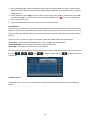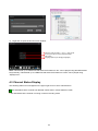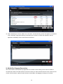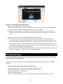
1
SEC-DVR504
SEC-SETDVR20
SEC-SETDVR30
SEC-SETDVR40
MANUAL (p. 2)
Full Manual
2012-09-20
Full Manual
CAUTION!
TO REDUCE THE RISK OF ELECTRIC SHOCK, DO NOT REMOVE COVER WHILE THE
DEVICE IS CONNECTED TO A POWER SOURCE. THE DEVICE’S INTERNAL PARTS
CANNOT BE SAFELY REPAIRED BY USERS. REFER SERVICING TO QUALIFIED SERVICE
PERSONNEL.
WARNING!
TO PREVENT FIRE OR ELECTRIC SHOCK HAZARD, DO NOT EXPOSE THIS APPLIANCE
TO RAIN OR MOISTURE.
NOTE: This device has been tested and found to comply with the limits (what limits? You
need to tell me) for Class A digital devices, pursuant to Part 15 of the FCC Rules. These
limits are designed to provide reasonable protection against harmful interference when
the device is operated in a commercial environment. This device generates, uses, and
can transmit radio frequency energy, and, if not installed and used in accordance with the
instructions in the user manual, may cause harmful interference with radio
communications.
FCC Caution: To ensure continued compliance, use only shielded interface cables when
connecting this device to computers or peripheral devices. Any changes or
modifications (COMMENT: changes or modifications to what? not expressly approved by
LB Tech could void the user’s authority to operate this device.
This Class A digital device meets all the requirements of the FCC Regulations.
2
LIMITATION OF LIABILITY
■
This user manual is supplied “as is”, with no warranties, be it expressed or implied, including, but not
limited to the implied warranties of merchantability, suitability for any exact purpose, or non-infringement
on any third party’s rights.
■
This publication may include technical inaccuracies or typographical errors. The manufacturer holds the
right to introduce any changes to the information contained herein for any purpose, including, but not
limited to improvements of the product and publications related to it, at any time, without prior notice.
DISCLAIMER OF WARRANTY
The supplier shall not be liable to any party or any person, except for replacement or reasonable maintenance
of this product, for the cases including, but not limited to the following:
■
Any damage or loss, including, but not limited to: direct/indirect, consequential, special, exemplary use
arising out of or related to the product;
■
Inappropriate use or negligence of the user during operation of the product, resulting in personal injury or
any damage;
■
Unauthorized disassembly, repair, or modification of the product by the user;
■
Any problems or consequential inconvenience, loss, or damage caused by connecting this product to
devices of the third parties;
■
Any claim or action for damages brought by any photogenic subject, be it a person or an organization,
due to invasion of privacy whereby the surveillance picture and/or saved data becomes public or is used
for purposes other than surveillance.
SAFETY INSTRUCTIONS
Read these instructions and keep them in a safe place for future reference.
■
Please refer all servicing related to the installation of this product to qualified service personnel or system
installers.
■
Do not operate the device under conditions outside its recommended temperature, humidity or power
source ratings.
■
Place the unit on a flat surface not prone to vibration or impact.
■
Use the appliance at temperatures between 0oC- 45oC (32oF -113oF) and humidity below 85%.
■
The input power source for this appliance should be between 90-230V AC, 47-63 Hz.
■
Install the unit away from heat sources such as radiators, heat registers, and stoves. Installation of the
unit near consumer electronics, such as stereo receivers/amplifiers and televisions, is permitted as long
as the air surrounding the terminal does not exceed the aforementioned temperature range.
■
Handle hard disk drives with care.
3
It is possible to damage hard drives if they are moved while their motors are still running. To allow the
hard drive to spin down and park its heads, wait at least 10 seconds after disconnecting it from a power
source before moving the unit.
To avoid shock and vibration damage to the internal hard drive, do not move the unit while it is plugged in.
Protect hard disk drives from static electricity.
Do not stack hard disk drives or keep them upright.
Do not use an electric or magnetic screwdriver to repair hard disk drives.
■
Do not impede the flow of air through the vents or place the unit in an enclosed area where the cooling
vents are blocked.
■
Protect the power cord from being stepped on or pinched, particularly at plugs and the points where they
connect to the device.
■
Do not drop metallic parts through slots, as this could permanently damage the device. If a metallic object
falls through the slots, turn the power off immediately and contact qualified service personnel for service.
■
Handle the device with care. Do not drop or shake it, as this may damage the device.
■
Do not expose the device to moisture or try to operate it in wet areas. Do not install the unit in an area
where condensation occurs. Do not operate with wet hands. Take immediate action if the appliance
becomes wet. Turn the power off and refer servicing to qualified service personnel, as moisture may
damage the appliance and cause electric shock.
■
Do not use strong or abrasive detergents when cleaning the body of the device. If dirt is difficult to remove,
use a mild detergent and wipe gently.
■
Do not overload outlets and extension cords, as this increases the risk of fire and electric shock.
■
Make a note of your settings and save them in a place where you can easily find them. This will help if it
becomes necessary to change the system configuration, or if an unexpected failure or problem occurs.
■
Distributing, copying, disassembling, reverse compiling, reverse engineering, and exporting the software
provided with this product in violation of export laws, is expressly prohibited.
CARING FOR THE ENVIRONMENT BY RECYCLING
When this symbol appears on a product, do not dispose of it with residential or
commercial waste.
Recycling Electrical Equipment
Do not dispose of this product with residential or commercial waste. Some countries
and regions, such as the European Union, have established systems for collecting and
recycling electrical and electronic waste items. Contact your local authorities for
information about practices established for your region
4
COPYRIGHT STATEMENT
All rights reserved. No part of this publication may be reproduced in any form or by any means, transcribed,
translated into any language or computer language, transformed in any other way, stored in a retrieval system,
or transmitted in any form or by any means, electronic, mechanical, recording, photocopying or otherwise,
without the prior written permission from the owner.
5
Table of Contents
LIMITATION OF LIABILITY ............................................................................................................................. 3
DISCLAIMER OF WARRANTY ....................................................................................................................... 3
SAFETY INSTRUCTIONS ............................................................................................................................... 3
COPYRIGHT STATEMENT.............................................................................................................................. 5
1.YOUR DVR AT A GLANCE........................................................................................................................ 9
2.Contents of the Package ........................................................................................................................ 10
2.1 Getting Started Checklist ............................................................................................................................................................... 10
3. Hardware ................................................................................................................................................... 10
3.1 Front Panel (Please take actual machine model as quasi) ........................................................................................................... 10
3.2 Back Panel (Please take actual machine model as quasi)............................................................................................................ 11
3.3 Remote Control (Please take actual machine model as quasi)..................................................................................................... 12
3.4 Mouse Control ............................................................................................................................................................................... 13
3.5 Hardware Installation ..................................................................................................................................................................... 13
3.5.1 Basic Connections............................................................................................................................................................... 13
3.5.2 Installing Hard Disk Drives (HDDs) ..................................................................................................................................... 14
4. Getting Started and the Main Screen...................................................................................................... 15
4.1 The Main Screen ........................................................................................................................................................................... 15
4.1.1 Displaying a Single Channel ............................................................................................................................................... 16
4.1.2 Status Bar ............................................................................................................................................................................ 16
4.1.3 Login DVR ........................................................................................................................................................................... 16
4.1.4 Tool Bar ............................................................................................................................................................................... 17
4.2 Tool Bar Menu Options .................................................................................................................................................................. 18
4.2.1 System Configuration .......................................................................................................................................................... 18
4.2.2 Manual Recording ............................................................................................................................................................... 18
4.2.3 Video Playback.................................................................................................................................................................... 18
4.2.4 Video Backup ...................................................................................................................................................................... 21
4.2.5 Playing Backed Up Videos on Home Computers ................................................................................................................ 23
4.3 Channel Status Display.................................................................................................................................................................. 24
5. DVR............................................................................................................................................................ 25
5.1 Menu Tree...................................................................................................................................................................................... 25
5.1.1 Menu Options ...................................................................................................................................................................... 25
5.2 System........................................................................................................................................................................................... 26
5.2.1 Language ............................................................................................................................................................................ 26
5.2.2 Video System ...................................................................................................................................................................... 26
5.2.3 Time Setup .......................................................................................................................................................................... 26
5.2.4 User Management ............................................................................................................................................................... 27
5.2.5 HDD (Hard Disk Drive) ........................................................................................................................................................ 29
5.2.6 Maintenance ........................................................................................................................................................................ 30
5.2.8 Information........................................................................................................................................................................... 30
5.3 Record ........................................................................................................................................................................................... 31
5.3.1 Record Channel .................................................................................................................................................................. 31
5.3.2 Record ................................................................................................................................................................................. 31
5.3.3 Recording Bit-rate ............................................................................................................................................................... 31
5.3.4 Record Resolution ............................................................................................................................................................... 31
6
5.3.5 Recording Frame Rate ........................................................................................................................................................ 31
5.3.6 Recording Pack Time .......................................................................................................................................................... 32
5.3.7 Recording Modes ................................................................................................................................................................ 32
5.4 Video.............................................................................................................................................................................................. 34
5.4.1 Channel ............................................................................................................................................................................... 34
5.4.2 Name ................................................................................................................................................................................... 34
5.4.3 Position................................................................................................................................................................................ 34
5.4.4 Live ...................................................................................................................................................................................... 34
5.4.5 Color .................................................................................................................................................................................... 34
5.4.6 Record Time ........................................................................................................................................................................ 34
5.4.7 Video Margin ....................................................................................................................................................................... 35
5.4.8 Video Setup ......................................................................................................................................................................... 35
5.5 Network.......................................................................................................................................................................................... 35
5.5.1 Network ............................................................................................................................................................................... 35
5.5.2 SUB-STREAM ..................................................................................................................................................................... 36
5.5.3 DDNS Setup ........................................................................................................................................................................ 37
5.5.4 Email Setup ......................................................................................................................................................................... 37
5.5.5 Mobile Setup ....................................................................................................................................................................... 38
5.5.6 IP Access Setup .................................................................................................................................................................. 39
5.5.7 ESMS Settings .................................................................................................................................................................... 39
5.5.8 FTP Settings........................................................................................................................................................................ 40
5.5.9 Other Settings ..................................................................................................................................................................... 40
5.6 Alarm.............................................................................................................................................................................................. 40
5.6.1 DURATION .......................................................................................................................................................................... 40
5.6.2 BUZZER .............................................................................................................................................................................. 40
5.6.3 PRERECORD...................................................................................................................................................................... 40
5.6.4 EXCEPTION ALARM .......................................................................................................................................................... 41
5.6.5 Motion Detection ................................................................................................................................................................. 41
6. Web Browser Operation .......................................................................................................................... 42
6.1 Feature .......................................................................................................................................................................................... 42
6.2 Network Security Setting ............................................................................................................................................................... 42
6.3 Connection Settings ...................................................................................................................................................................... 44
6.4 Control Download and Installation ................................................................................................................................................. 45
6.5 Operation Interface ........................................................................................................................................................................ 46
6.5.1 Live ...................................................................................................................................................................................... 46
6.5.2 Controls ............................................................................................................................................................................... 47
6.5.3 Other Operations ................................................................................................................................................................. 47
6.5.4 Replay ................................................................................................................................................................................. 48
6.5.6 Remote Settings .................................................................................................................................................................. 49
6.5.7 Local Settings ...................................................................................................................................................................... 58
6.5.8 Logout.................................................................................................................................................................................. 58
7. Wap Connection ....................................................................................................................................... 59
8. Mobile Phone Support ............................................................................................................................. 60
8.1 Windows CE Mobile Phone ........................................................................................................................................................... 60
8.2 Symbian S60 3rd and 5th Edition Phones ..................................................................................................................................... 61
8.3 Apple iPhone.................................................................................................................................................................................. 65
7
8.4 Android Mobile ............................................................................................................................................................................... 67
8.5 BlackBerry Mobile.......................................................................................................................................................................... 69
Troubleshooting ........................................................................................................................................... 77
Appendix 1. Setting up Internet Connections for Remote Access .......................................................... 79
Appendix 2. DVR-Compatible Hard Disk Drives ........................................................................................ 80
Appendix 3. DVR- Compatible Portable Wireless Mouse ......................................................................... 80
Appendix 4. Accessing the DVR via Mozilla Firefox ................................................................................. 80
Appendix 5. Accessing the DVR via Google Chrome ............................................................................... 81
Appendix 6 How to Use Auto ID – “Plug n play” Quick Guide ................................................................. 83
8
1.YOUR DVR AT A GLANCE
Product Overview
Model
4 CH
Video Format
PAL/NSTC
Video Compression
H.264 Baseline Compression
Video Input / Output
BNC 4CH Input / 1CH Output
Alarm Type
Motion detection, Video Loss, HDD loss
Display Frame Rate
Each Channel PAL:25 FPS, NTSC:30 FPS
Playback Resolution
CIF/HD1/D1 @ Recorded frame rate
Recording Speed –
frames per second
(FPS)
Recording Modes
PAL: 100 FPS@CIF, 100 FPS @ HD1, 50 FPS @ D1.
NTSC: 120 FPS @ CIF, 120 FPS @ HD1, 60 FPS @ D1.
Power-on Auto Record, Scheduled Record (Normal Recording, Motion Detection),
Manual Recording
HDD Interface
SATA Interface support 2TB, HDD*1
Network Protocol
TCP-IP/ DHCP/DDNS/PPPOE/E-Mail
Network Functions
Live Monitoring, Playback, Configuration, Backup, Mobile Phone Surveillance
USB 2.0 Interface
Mouse / Portable Mobile HDD/ Flash Drive/ Firmware Upgrade
Playback Options
Normal, Fast Forward, Slow Forward, Rewind, Single Step
Network Interface
RJ45 10M/ 100M Ethernet Auto-Detect
Area Covered
Each channel supports coverage of four different areas
Video Backup
h.264 or .avi
Power Adapter
DC 12V
Power Consumption
10-15W
Operating
-10°C-+40°C
Temperature
Operating Humidity
10%-90%
Dimensions
250(W) *218 (D) * 42 (H) mm
Congratulations on purchasing a state-of-the-art Digital Video Recorder (DVR). This DVR offers the industry’s
best triplex functionality with video/audio recording, playback, and network capability, which can all be run
simultaneously, streamlining the use of CCTV systems and boosting the security level of the home, business,
or social venue where it is installed. Users can access live or recorded feed from standard cameras directly at
the location of the DVR installation, or anywhere in the world using web-browsers or a mobile phone. The
video may be stored at a remote location for safety.
9
(Some limitations apply to Web- and phone-based features; please see the related sections for more detailed
information.)
Users are advised to become familiar with the DVR’s parts and accessories, as well as how to use the device
as described in this instruction manual. For any questions that this guide does not answer, please contact a
local vendor or a certified specialist.
In this manual, “-ch” and “CH” are used as abbreviations for “channel”, so, for example, “4-ch” means
“4-channel” (i.e. a 4-channel DVR model).
2.Contents of the Package
•
Digital Video Record (DVR)
•
User manual
•
Installation CD
•
Remote control
•
Power cord
•
Mouse (varies by model)
•
Hard disk drive (varies by model) (if you would like to use your own hard disk drive(HDD), please see
Appendix 2. DVR-Compatible Hard Disk Drives for a list of compatible HDDs)
2.1 Getting Started Checklist
Before setting up this DVR, check to make sure the answer to all of the following questions is “yes”:
a) Are the power and video in/out cables plugged in? Please see Section 3.5.1 Basic Connections for more
information.
b) Has the HDD been properly installed and formatted? Please see Sections 3.5.2 Installing Hard Disk
Drives (HDDs) and 5.2.5 HDD (Hard Disk Drive) for more information.
3. Hardware
3.1 Front Panel (Please take actual machine model as quasi)
The appearance of the front panel varies slightly with each different DVR model.
This subsection will explain the functions of each of the buttons and other components on the front panel of
the DVR.
buttons
•
Using these buttons, you can choose to display video on your monitor either as a full-screen view of each
of the cameras individually (
•
,
,
,
,
), or all channels simultaneously (
).
buttons
Use the arrow buttons to select menu items. Press the “Enter (
10
)” key to confirm your choice.
•
Power LED, Record LED
LED lights indicate the DVR’s connection to the power supply, recording status
•
): Press this button to access the toolbar, hide the toolbar, enter or exit from the menu, and
Menu (
enter or exit sub-menus.
•
Rewind (◄◄): Press this button to rewind the video during playback.
•
Play/Pause (
): Pres this button to open the video search function and the playback menu. When the
playback mode is activated, press this button to play/pause playback.
•
Stop (■): Press this button to stop playback.
•
Fast Forward (►►): Press this button to fast forward the video during playback.
•
REC (●): Press this button to start or stop manual recording.
•
IR Window (
•
USB Connector: Use these USB ports to connect backup devices (i.e. flash drives, USB DVD recorders,
): Infrared sensor for remote control.
etc.) or a mouse to the DVR. —— (Optional)
NOTE: On live view, press the
button 10 times when there is no toolbar, and this will switch the main
menu between CVBS video output and VGA video output.
3.2 Back Panel (Please take actual machine model as quasi)
1
4
3
2
5
7
6
1. USB connectors
Use these USB ports to connect the mouse and backup devices (flash drives, portable mobile HDD) to the
DVR.
2. VGA Connector
For connecting the DVR to a VGA/LCD monitor
3. Video Input Connectors (Video IN 1-4)
4 channels video input connectors for connecting to analog video signal input (BNC, 1Vp-p, 75Ω)
11
4. Power Input Socket (12V DC)
5. Ethernet Connector
RJ-45 10/100 Base-T Ethernet network
6. Video Output Connector
Video output for connecting the DVR to a monitor or TV, (BNC, 1Vp-p, 75Ω)
7. Ground
3.3 Remote Control (Please take actual machine model as quasi)
Pressing the “enter” key on the remote control or the front panel of the DVR has the same function as
left-clicking a mouse. The functions of the buttons on the remote control are identical to the functions the
buttons with the same markings on the front panel of the DVR.
Stop (■): Press this button to stop playback.
Play/Pause (
): Press this button to open the video search function and the playback menu. When the
playback mode is activated, press this button to play/pause playback.
(
): Move selected item in menu.
Menu (MENU/ESC): Press this button to access the toolbar, hide the toolbar, enter or exit from the menu, and
enter or exit sub-menus.
Lock (
): the password is enabled, press this button to log out of the system.
Numerical Buttons: Using these buttons, you can choose to display video on your monitor either as a
full-screen view of each of the cameras individually (Channels 1 through 4).
Rewind (◄◄): Press this button to rewind the video during playback.
Fast Forward (►►): Press this button to fast forward the video during playback.
ENTER: This button is used as the “enter” key in most circumstances (i.e. for selecting items from a menu).
Spot View (
): Press this button to enable auto sequencing.
Mute ON/Mute Off (
Quad (
): Press this button to turn the sound on or off.
): Press this button to switch display modes to all channels simultaneously.
REC (●): Press this button to start or stop manual recording.
12
3.4 Mouse Control
As well as the remote control and the buttons on the DVR itself, you can use a mouse to operate the DVR.
The mouse operates just like a mouse on a typical computer. To start, connect the mouse to the USB port in
the back panel of the DVR; note that you can hot-plug the mouse.
Right-clicking
In live view, right-clicking will either display or hide the toolbar.
From the main menu or a sub-menu, right-clicking will exit the current menu. Note that
any changes to settings will not be saved after right-clicking.
Left-clicking
In menu unlock mode, left-clicking on the SYSTEM SETTINGS icon in the tool bar will
open the main menu.
After entering the main menu, left-clicking will open sub-menus.
In the “detail files” menu mode, left-clicking will play back one recording file.
By left-clicking, you can select values in edit boxes or pull down menus The system
supports the input of Chinese characters, and other special symbols, numbers, and
letters.
On the playback interface, left-clicking can control the fast-forward function, the
rewind function, the slow-motion function, frame-by-frame playback function, the
normal play function, and can stop any of these processes or be used to exit from a
mode or menu.
Left-clicking can be used to access the color control bar, the volume control bar, and
the screen control bar.
From the main menu, sub-menus, or playback view, left-clicking “x” will exit the current
menu.
Left-clicking can also be used to select menu items.
Double-clicking
left mouse key
Mouse drag
In live view or video playback, double-clicking will maximize the screen.
In the motion detection setting interface, you can left-click and then drag the frame to
set the motion detection area.
3.5 Hardware Installation
It is recommended that the installations described below be carried out by qualified personnel.
3.5.1 Basic Connections
■
Cameras
Connect each of the cameras’ outputs to the video input sockets in the rear panel of the DVR using the
appropriate cables. The video input interface is a standard BNC connector, 1Vp-p, 75 Ω. Keep the video
signal cable away from strong electromagnetic and electric interference.
■
Monitor
Connect the main output connector to a monitor or a TV screen. Use a BNC-to-RCA converter, if needed,
to work with the Audio/Video RCA cable.
13
■
Power
Use the 12V DC adapter supplied for connecting your DVR device to the power source.
■
Ethernet
For remote access to the video images from your cameras via LAN or Internet, connect a standard RJ-45
twisted-pair Ethernet cable to the Ethernet port.
■
USB
Use this port for connecting the mouse or USB flash drives. The USB mouse can be hot plugged.
NOTE: The device only supports the FAT32 file system on USB devices.
3.5.2 Installing Hard Disk Drives (HDDs)
Before you can record onto your HDD, it must be formatted by the DVR system because
standard PC formatting is not compatible with the DVR. It can be done through the
“Maintenance” tab of the main menu in the toolbar. Refer to Section 5.2.5 HDD (Hard Disk
Drive) for a detailed description of this process. Depending on the size of your HDD, the
formatting process can take up to several minutes.
Power connector
Data connector
The HDD should be installed inside the DVR. Connect the HDD
in according to the instructions, screwing the HDD into the HDD
brackets or DVR base. All necessary cables are included with
the DVR. If using a hard drive from another manufacturer, use
instructions that came with the hard drive for specific details on
proper wiring and installation. Connect the power cable to the
appropriate socket, and connect the data cables to their
corresponding ports.
14
For a list of HDDs tested and approved for compatibility with
DVRs, see Appendix 2. DVR-Compatible Hard Disk Drives.
4. Getting Started and the Main Screen
1) Turn on the DVR and wait for the system program to load. If any of the following conditions are true.
•
You have not yet installed a hard disk drive into the device.
•
The DVR cannot read the HDD.
•
If a new HDD has been installed in the DVR but has not yet been formatted.
•
There is not enough space on the HDD to record, it will display a red “X” icon (
) in the video preview
interface. The HDD must be formatted in the DVR before use.
To format the HDD, first, from the main menu, select “System settings.” Click “SYSTEM”, then select “HDD
management”, and lastly, select “format.” If the HDD is already installed, the default setting is for the DVR to
start recording and a red dot icon (
) on the screen will indicate that it is functioning normally.
4.1 The Main Screen
The standard layout is four windows evenly distributed over the screen. From the main screen, you can
access menu options and switch among channel views, displaying either all channel feeds simultaneously or
displaying a full-screen view of a single selected channel.
15
4.1.1 Displaying a Single Channel
In the multiple-screen view, you can make a particular window active by left-clicking on it once with a mouse,
or navigating to it using directional buttons (
,
,
,
).
To display a full-screen view of a single channel, press the corresponding numerical or positional buttons (
) on the front panel; alternatively, you can do so by left double-clicking on the desired window.
In order to return to the multi-screen view, either double-click on the screen again or press the
single-/multiple-view button either on the remote control or the front panel of the DVR.
You can choose to display the status bar and or toolbar, or to hide them by right-clicking on the screen. These
three options alternate in sequence.
4.1.2 Status Bar
Located at the bottom of the screen, the Status Bar can be displayed by pressing the “Menu” button or
right-clicking anywhere on the screen.
System time
Approximate Remaining Hours of HDD recording
4.1.3 Login DVR
In live view, press the “
” button twice or double-click the right
key of the mouse in live view to display the tool bar. The login window
will appear if the password is enabled.
You can log in from the “LOGIN” window as shown in the adjacent
figure. Select a user name and password via numeric keyboard. You can access the main menu by pressing
“
” if the password is enabled.
1. The default password for Admin is “888888” and the default password for user1 is “666666”. For your
convenience and system safety, you can change password of Admin and add another username.
2. The Device ID is used for connecting the Internet Explorer interface. For detailed instructions please refer
to Appendix 6.
16
4.1.4 Tool Bar
After logging in system, double-click the right-hand mouse button, and it will display the following toolbar.
PLAY
SYSTEM SETTINGS
KEYLOCK
SEQ
MANUAL REC / STOP MANUAL REC
EZOOM
PIP1*1
PIP1*2
VGA/BNC SWITCH
The functions of the buttons in the toolbar are as follows:
System configuration
Search, playback, and backup of recorded files
●/
MANUAL REC/STOP MANUAL REC: Click the? “MANUAL REC” button to start manual recording.
Click “STOP MANUAL REC” or press the “stop” (“■”) button to stop manual recording.
KEYLOCK: If the password is enabled, clicking “KEYLOCK” will log the user out of the system and lock
the DVR such that pressing keys or icons will have no effect on DVR activity until a user enters the password
to disable the keylock.
AUTO SEQUENCE: Click “AUTO SEQUENCE” on the toolbar to enable auto- sequencing; this will
display the channels with images in sequence: channel 1-channel 2-channel 3-channel 4-channel
1……Channels without images will not be displayed. To interrupt auto- sequencing, press any button or click
the mouse while in auto-sequence mode.
EZOOM: Click “EZOOM” to enter zoom mode, and then left-click and drag the cursor to select the area to
be magnified. Right-click to exit zoom mode.
PIP 1*1: This feature displays the video from one channel in a small inset window, while another channel
is displayed in full-screen view.
PIP 1*2: This feature displays two channels in small, inset windows, while another channel is displayed in
full-screen view.
VGA/BNC SWITCH (video output switch): Press the “
” ten times when the toolbar is not visible or
click “VGA/BNC SWITCH” on the toolbar, and this will switch the main menu between CVBS video output and
VGA video output.
See the following subsections for a detailed description of each of these functionalities.
17
4.2 Tool Bar Menu Options
4.2.1 System Configuration
After pressing this button, a screen for configuring all system settings will appear. From this screen,
system and network settings, and settings for recording, video playback, alarmscan be adjusted. Refer to
Section 5. DVR for a detailed description of these settings.
Note: In order to for changes to sub-menu settings to take effect, it is necessary to press “
to the sub-menu settings will not be saved if you do not press “
”. Changes
” and exit the sub-menu immediately
afterward. A special feature of this DVR is that an explanation of each menu item will be displayed
automatically when the cursor is moved over it.
4.2.2 Manual Recording
There are three ways of recording live video/audio feed from your cameras: manual recording,
scheduled recording, and continuous recording.
If scheduled recording is in conflict with manual recording, the manual recording will be processed first until
stopped.
For a detailed description of scheduled recording, see Section 5.3.7 Recording Modes.
In order to manually record a video/audio feed, select the “Manual Record” button from the “Tools” menu.
Alternatively, you can press the “REC” button on the remote control or the front panel of the DVR. Pressing
“Manual Record” or “REC” again will stop the recording process.
4.2.3 Video Playback
To start video playback, first move the cursor to “►” (the icon will be highlighted when selected) and left-click it
to enter the settings menu; alternatively, press the “►ll” button to enter the settings menu.
There are two methods of searching for recordings:
Method 1: Playback by Date
Date input: Adjust the date and time to match the recording you are searching for: first, select “TIME” and
press “Enter” to input numbers directly to set the year, month, and date; next, input the time in the next field,
and click “►”. A window that reads “CHOOSE PLAYBACK CHN” (see the following figure on the right) will
automatically appear; in this window, choose channel of the video to be played, and click “►”. If only one
channel is selected, the video from that channel will be displayed in full-screen mode. If two or more channels
are selected, the videos from the selected channels will be displayed simultaneously over four frames.
18
Instructions:
CHN: CH1, CH2, CH3, CH4 and ALL
MONTH: This option will show all the recordings in a given month. A green background on the calendar
indicates normal recording; an orange indicates this file is a motion-detection recording, and a gray
background indicates that there was no recording. Click any date in this frame to search by the recording
status of that day, and the search results will be shown in the date frame.
DATE: This option will show all the recordings and their statuses on the selected day, and the recorded files in
any period can be displayed by clicking on their corresponding period.
Method 2: playback by recording status:
Input the date, click “search” and the recording status on that date will be displayed.
Instructions:
1. “FILE LIST”: “CHN” shows which channel the file was recorded under, “TIME” shows the recording time,
and “SIZE” is the size of this file (listed in MB). An orange indicates this file is a motion-detection recording
file list, and a black list indicates this file is a normal recording file. Pressing the “SELECT” button will
export the selected files to a USB storage device.
2. After moving the cursor up or down and selecting the files, left-click to enter the playback menu. It will play
the video from a single channel in full-screen view.
19
3. If the “RECORD TIME” section is marked as “ON” under the “VIDEO DISPLAY” section, it will show the
date/time that the video was recorded when playing back recorded file; if it is marked as “OFF”, it will not
display the time.
4. During playback, press “►►▌”to play the video in slow-motion; press “►►” to fast forward; press “◄◄”
to rewind; press” ▌►” to pause and run frame-by-frame playback; press “
” to exit from playback and
return to the former menu.
5. When the selected files finish, the screen will return to the file list menu.
LOG SEARCH
Move the cursor over the “►” icon(the icon will be highlighted when selected) and left-click to enter the “REC.
SEARCH” setting menu, or press the “►/║” button to enter the settings menu, move the cursor over the “LOG”
option and press the “ENTER” button or left-click to access the Log Search option(as shown in the following
figures).
At the top of the “Log Search” page are the following filters to facilitate locating the desired file(s):
“LOG TYPE”: Choose from the following options: “All”, “ALARM”, and “OPERATION.”
“STARTING TIME”: Set the starting time of the log being searched for.
“END TIME”: Set ending time of the log being searched for.
Click the “Search” button after setting the log time and type, and the system will display the selected log in the
list. Click “
”, “
”, “
” and “
” to navigate pages, and click “
” to save the log list to
a USB drive.
Playback Control
In playback mode, users can view the playback control panel as well as the date and time of the file being
played.
20
The following are the functions of and options for the items in the playback control panel:
Fast rewind: the available speeds are 2x, 4x, 8x, 16x, 32x, and 64x.
Slow forward: the available speeds are 1/2x, 1/4x and 1/8x.
Play
Pause/Frame-by-frame view
Fast forward: the available speeds are 2x, 4x, 8x, 16x, 32x, and 64x.
EZOOM: While the video is playing normally, click this icon to enter zoom mode, and then left-click and
drag the cursor to select the area to be magnified. Right-click to exit.
Close.
4.2.4 Video Backup
Backup of videos can be initiated from the same dialog window as the playback function.
You can use USB devices for backup by inserting a USB device into the USB 2.0 port before backing up files.
The DVR also supports USB OTG (USB On-the-Go).
From the “FILE LISTING” menu, recording files can be selected using the direction keys. Press “Enter” to
confirm a selection. A checkmark (√) will appear at the end of the filename after the selection has been made
(pressing “Enter” again will cancel the selection, and the “√” will disappear). Once the files have been selected,
they can be exported by selecting “Backup.”
21
U-DISK Backup by Time
Note: In standard English, a “U-DISK” would be called a “USB storage device.” (the term “U-DISK” referred to
in this manual and the software for this DVR is a direct translation of the Chinese word for “USB drive”).
Move the cursor to “►” (the icon will be highlighted when selected) and left-click it to enter the “REC.
SEARCH” settings menu or press the “►/║” button to enter the settings menu; select “U-DISK backup by
time”, and press the “ENTER” button or left-click to access the “U-DISK backup by time” search option(as
shown in the following figure).
Note:
1. If the backup device being used does not have enough free space to save the file, a “not enough space”
warning will appear.
2. The USB device can be removed immediately after the backup is complete.
3. If the system cannot recognize the connected devices, or if none are connected, a “No USB DISK!”
warning message will appear.
4. If a USB drive is used to back up file, and the file format is AVI, the file can be played using Windows
Media Player. If the file format is H.264, it can be played on home computers using “Hsplayer.exe.”
With the current models, external media as USB flash drives, portable USB HDDs can be connected to DVRs.
The system only supports the FAT32 file system for USB flash drives and HDDs.
22
4.2.5 Playing Backed Up Videos on Home Computers
1) Copy the program “Hsplayer.exe” from the installation CD to the computer to be used. Double-click the
“
” icon to run the program.
Maximize the window
Close the Window
Maximize the window
Open
Capture
Setting
2) Click “
Play
Slow Fast
Mute Volume Slide
Next Frame
” to open the video recorder in “*.avi” or “*.264” format. Select a file and click”Open”to play the
file.
3) Click “
” to capture a still picture. Then, click “
” to enter the “Settings” menu to set up the path for
saving captured images. Click “Browser” to change the path for captured images. For example, select the
folder “Desktop” and click “OK” to save the path.
23
4)
Right-click to open the shortcut menu window.
Open the video recorder in “*.avi” or “*.264” format
To set up the path for saving captured images
Full Screen
Language options (for changing languages)
Note: Files backed up on USB drives that those file formats are “AVI” can be played using Windows Media
Player directly. Files backed up on USB drives that those file formats are “H.264” can be played using
“Hsplayer.exe”.
4.3 Channel Status Display
The following status icons will appear in the upper right corner of each channel frame.
This indicates that the channel has detected motion while in motion-detection mode.
● This indicates that the channel is running in normal recording mode.
24
5. DVR
5.1 Menu Tree
5.1.1 Menu Options
In order to modify/adjust the system configuration, it is necessary to enter the “System” menu; to do this, click
the “Settings” icon (
) in the “Tools” menu.
After clicking the “Settings” icon, a dialog box with settings for all of the systems and options available for the
DVR will appear. The settings are divided into five subsections, each with its own tab in the sidebar on the
left-hand side of the screen: “Record”, “Video”, “System”, “Network”, “Alarm”. The following are detailed
descriptions of these settings.
The “System” tab provides access to the general system settings for the DVR. The titles of the menu items
are located on the left, and the corresponding adjustable or non-adjustable values for these items can be
found in the fields to the right.
Users can:
(a) Select the values from a list (by toggling through the preset data by clicking the arrows on each side of the
field);
(b) Input the required data after entering a window where custom data can be entered by pressing the “>>”
button in some of the fields;
25
(c) Use the menu to become familiar with the existing non-adjustable settings.
When making selections from the fields or entering information into them using the remote control directional
keys or the DVR front panel, as well as when positioning the cursor over them, a short description of the
settings in question will appear at the bottom of the window.
Several tabs have options that are located in more than one window, and they can be found by navigating
among the windows by clicking “
”.
5.2 System
Move the cursor to select “SYSTEM” (the tab will be highlighted when selected) and press “Enter”to enter the
“System” menu.
5.2.1 Language
Use this field to change the language of the DVR menu text and the on-screen display.
5.2.2 Video System
From this field, select the system output type that is consistent with camera input, i.e. PAL or NTSC.
Note: The device will restart if the camera output type is changed.
5.2.3 Time Setup
Click “System settings”, then “System”, and then select “Time” to enter the “Time Setup” menu.
26
DATE: Set the date using the numerical keypad.
DATE FORMAT: Press “Enter” to switch the date format, include YY-MM-DD, MM/DD/YY and DD-MM-YY.
TIME FORMAT: Press “Enter” to switch the time format from a 12-hour clock to a 24-hour clock and vice
versa.
TIME: Set the system time using the numerical keypad.
DST: Daylight Savings Time. When “On” is selected in this field, DST is enabled. Users can set the starting
time and ending time of DST.
Note: It is necessary to click “
” to save the changes after modifying the time and date; the changes will
not be saved if you exit “Time setup” without clicking “
”.
5.2.4 User Management
To enter the “User Management” menu, first click “System settings.” Next, click “System”, and then select
“User Management.”
From this window, users can identify the device ID for the DVR and to change the password for the system. In
the “Password” field, select “On” and click “
” to save the setting.
DEVICE ID: In this field, to identify the device.
PASSWORD: In this field, a password for accessing the DVR system can be set or changed.
The following settings can only be set by the system administrator (who will be referred to throughout this
manual as “the Administrator”; the username for the system administrator is “Admin”):
27
ADD USERS: Add new users. In this window, enter the new
user’s name and password in the corresponding fields, and
then to confirm the password, enter it a second time in the
“Confirm Password” field. The length of the password must not
exceed 6 digits.
CHANGE PASSWORD: From this window, the Administrator
can change the system’s password. For security reasons,
before a new password can be set, it is necessary to enter the
original password.
DELETE USER: From this window (see the following figure to the left), the Administrator can delete users by
selecting the username of the user account to be deleted and clicking “
” to save the change.
SET PERMISSION: This allows the Administrator to give each user permission to access a unique set of DVR
functions. That is, the Administrator can give a user access to one, some, or all of the following functions:
Manual Recording, Playback/Backup, System Settings, Ezoom, PIP, Auto-sequencing, and
Update/Reboot/Maintenance/Format/Default, and the set of functions that one user is allowed to access may
include functions that are different from the set of functions that another user is allowed to access (see the
following figure to the right).
REMOTE PERMISSION: This is a very important function for remote operation of the DVR. The Administrator
can use this function to set each user’s remote access permissions, such as access to Record/Capture,
Playback/Download, Setting from a computer that is not on the local network (see the following figure to the
left).
28
VIEW PERMISSION: Another very important function for the Administrator is “View Permission”, which allows
the Administrator to set different viewing permissions for different users (see the preceding figure on the right).
The Administrator can decide which channel(s) each user is allowed to view. The Administrator has
permission to view all channels, and this permission cannot be modified.
After the password verification is set up (marked “ON”) the Administrator can set up to seven user passwords,
as well as an Administrator password. If the password function is enabled, it will be necessary to enter the
password before logging in.
Note: Once the password has been enabled, it is necessary to log in to the system as “Admin” in order to
manage users; The Administrator’s username (“Admin”) cannot be modified.
The default password for Admin is “888888” and the default password for User1 is “666666”.
5.2.5 HDD (Hard Disk Drive)
First, click “System Settings”, then click “System”, and then select “HDD” to enter the “HDD Management”
menu (see adjacent figure).
STATE: There are three available statuses: “OK”,
“un-format”, and “No Disk.” If the HDD cannot operate
normally (including when the status is “unformatted” or
“no HDD”), there will be a “
” icon displayed on video
live view. If a new HDD is used with the DVR for the first
time, please format the HDD.
TOTAL/FREE: This field indicates amount of space
available and the amount of unused space available on
the hard disk drive.
FREE TIME: Indicates remaining recording time on the HDD.
OVERWRITE: Includes “CLOSE, AUTO, 1 HOUR, 3 HOURS, 1 DAY, 2 DAYS, 7 DAYS, 30 DAYS, and 90
DAYS”. If a user chooses “CLOSE”, the recording stops when the hard disk drive is full. Once the hard disk
drive is full, it will not record again until “overwrite” is enabled. If a user chooses “AUTO”, recording continues
and overwrites previous recording when the hard disk drive is full. If a user chooses “2 DAYS”, recording on
the hard disk will continue for no more than two days. After two days, the recording will be automatically
29
overwritten. The “7 DAYS”, “30 DAYS”, and “90 DAYS” options are similar to the “2 DAYS” option, except that
instead of recording for two days before the automatic overwrite takes place, recording will continue for 7 days,
30 days, and 90 days, respectively before being overwritten.
FORMAT HDD: Move the cursor to select the device to be formatted, and click “HDD” to begin formatting.
FORMAT USB: This enables users to format the USB device connected to the DVR.
5.2.6 Maintenance
To enter the “Maintenance” menu, click “System Settings”,
then click “System”, and select “Maintenance.”
SYSTEM UPDATE: Create a new root directory called
“dvrupgrade” on a USB flash drive, copy the update file to it,
and then insert it into USB port of the DVR. Press “Enter” to
upgrade the firmware and it will display the process of the
system upgrade.
The system upgrade will require at least two minutes;
during this time, do not remove the USB drive or turn the DVR off. After completing the upgrade, the DVR will
restart.
LOAD DEFAULT: Selecting this option restores all the settings to the original factory settings.
REBOOT: Use this function to restart the device.
POWER OFF: Use this function to turn off the device.
AUTO MAINTAIN: When “AUTO MAINTAIN” is on, users can set a specific time for the DVR to restart. The
system will restart automatically according to the parameter(s) chosen.
5.2.8 Information
Click “System Settings”, then click “System”, and select
“Information” to enter the “System Info” menu. The
information included accessible through this interface
includes: the device type, the software version, the release
date, import parameters, and export parameters. It is
necessary to export parameter to a USB drive before
importing any parameter from the USB drive; otherwise, it
will not be possible to successfully import the parameter.
30
5.3 Record
Move the cursor over the “RECORD” tab (the icon will be
highlighted when selected). Press “Enter” to enter the
“Record” settings interface. The direction keys and cursor
can be used to change the settings.
5.3.1 Record Channel
After clicking the “Channel” tab, users can modify the
settings of the camera connected to the selected channel.
Alternatively, users can make the same change (or set of
changes) to the settings of all of the cameras at once. To apply the change(s) to all available channels, first
select “All” from the “Channel” field by pressing the arrow buttons; the options include CH1, CH2, CH3, CH4
and ALL. Then make the desired changes and save them before exiting the menu.
5.3.2 Record
“ENABLE” indicates that the channel is enabled for recording.
5.3.3 Recording Bit-rate
There are three options: “GOOD”, “NORMAL”, and “LOW”, corresponding to “HIGHEST”, “HIGH”, and
“NORMAL” data stream standards, respectively. The recording bit rate of each channel can be adjusted
independently.
5.3.4 Record Resolution
This indicates the setup resolution and code rate for recording. There are three options: D1, HD1, and CIF
resolutions. The recording resolution of each channel can be adjusted independently.
5.3.5 Recording Frame Rate
In this window, users can choose the recording frame rate (frames per second) for the current channel. The
higher the recording frame rate, the more natural the movement seen in playback mode will seem. Select a
recording frame rate depending on the how carefully the activity in the video needs to be monitored. It is
possible to adjust each channel frame rate independently.
For the PAL video output format, the system’s default resolution is CIF, and the system’s default frame rate is
25 frames per second with each channel; this means the system will record 100 frames per second with all
channels running (if there are four channels that are all recording). Users can set the frame rate from 1 to 25
frames per second for each channel. The maximum value of total frames recorded per second with all
channels is 200 frames with CIF resolution.
For the NTSC video output format, the system’s default resolution is CIF and the system’s default frame rate
is 30 frames per second for each channel, which means the system will record 120 frames per second with all
channels running (if there are four channels that are all recording). Users can set the frame rate from 1 to 30
frames per second for each channel. The maximum value of total frames recorded per second with all
channels is 240 frames with CIF resolution.
31
5.3.6 Recording Pack Time
There are four options: 15 minutes, 30 minutes, 45 minutes, and 60 minutes. It will pack as the mode selected
when alarm recording is disabled.
5.3.7 Recording Modes
There are two recording modes: “ALWAYS” and “SCHEDULE”.
ALWAYS: In this mode, the DVR will automatically begin recording when it is turned on.
SCHEDULE: This setup function allows users to
create a schedule for recording tasks throughout the
week, so that only certain selected events are
actually recorded on the HDD. For example, users
can set up the system to record non-stop only during
the business hours, and to run motion-detection
alarm-triggered recording with certain hours (which
means no recording will take place unless a
motion-detection event happens) Additionally, the
recording schedule can include specific no-record
time slots for when users are usually in the office (or
other location where the camera is installed) alone at very early hours of weekday mornings. The schedule
can be easily customized to the user’s needs.
Note: manual recording overrides all other recording settings and will take place until a user stops the
recording or changes the recording mode.
CHANNEL: Users can select all channels or a single channel.
There are three modes for recording: “MD”, “NORMAL”, “NO RECORD”, Different colors are used to identify
the different recording modes: Orange refers to “MD record”, green refers to “normal record”, gray refers to
“no record”.
To set up weekly schedules, click on the box of the recording status to be used (MD, Normal, or No record)
and then click on each box in the schedule timeline that this recording status is to be applied to. See the
“Record Schedule Setup” screenshot in the preceding figure. Each gray block represents one hour on a
24-hour clock, i.e. the first block(next to each day of the week) represents the hour from midnight-01:00 AM
and the last block (below the “23” on the right hand side of the screen) represents the hour from 11:00
” button at the bottom of the screen to save it.
PM-midnight. After setting the schedule, click the “
Alternatively, left-click to drag the frames of the boxes in the schedule timeline where you want to.
Another way to set up schedules is to create a schedule for one day of the week, and then use the “FROM”
and “TO” dropdown menus and COPY button settings to apply the setting from one day to another day or a
series of up to all seven days of the week. To do this, first create a schedule for one day. Then, from the
“FROM” dropdown menu, select the first day of the week that the schedule should apply to. Next, from the
“TO” dropdown menu, select the last day of the week that the schedule should apply to, and click “COPY”. For
32
example, to set a schedule where the DVR uses MD recording from 2:00 AM until 1:00 PM, and normal
recording from 1:00 PM until 10:00 PM on Tuesdays, Wednesdays, Thursdays, and Fridays, the process
would be as follows:
1. Click the orange box at the bottom of the screen to select “MD record”. Then, in the row of gray boxes
next to the “TUE”. box, click all of boxes from the third box from the left to the box under the “12” at the top
of the timeline(the box directly under the “12” should be selected) in order to select the hours between
2:00 AM and 1:00 PM.
2. Click the green box at the bottom of the screen to select “normal record.” Then click all of the boxes in the
same row from the box immediately to the right of the box under the “12” at the top of the timeline to the
third box from the right to select the hours from 1:00 PM-10:00 PM.
3. The preceding steps set a schedule for Tuesday, which can now be copied to Wednesday, Thursday, and
Friday. To copy it, from the “FROM” field, first select “Tues”.
4. In the “TO” field, select “Fri.” and then click “COPY.”
5. To save this schedule, click the “
” button at the bottom of the screen.
Regardless of whether the schedule is set for each day individually or by copying one schedule to multiple
days of the week, it is necessary activate it by clicking the “
” button. Without clicking the “
”
the schedule will not take effect.
When the alarm recording mode is selected, in order for the actual recording to take
place, it is necessary to set the motion detection sensitivity and area. Refer to Section
5.6.5 Motion Detection for detailed instructions. When alarm recording is selected, make
sure to set the alarm trigger settings beforehand.
Scroll to
and press “Enter” to restore default settings.
Scroll to
and press “Enter” to save new settings.
33
5.4 Video
Move the cursor over the “VIDEO” tab (the tab will be
highlighted when selected). Press “Enter” to enter the
video settings menu. The direction keys and cursor
can be used to change the settings.
5.4.1 Channel
Use this field to select a channel to set up, or to
modify its settings.
5.4.2 Name
Users can modify the name of the camera for each channel. Note that the name of the camera for each
channel must not exceed nine Romanized letters or four Chinese characters.
5.4.3 Position
Naming the location is optional. By pressing “Enter”, users can switch between “U-L”, “D-L”, “U-R”, “D-R”, and
“OFF”.
5.4.4 Live
When this field is set to “ON”, the selected channel can be viewed in live view mode; when “OFF” has been
selected, it cannot.
5.4.5 Color
To enter the “Color Setup” menu, click “System Settings”, then click
“Video” and select “Color.” From this menu, the video color
attributes can be adjusted for the best image quality. By default, the
values are set at 31, as this is the median value. Make adjustments
to the hue, brightness, contrast, and/or saturation as appropriate
depending on the actual conditions at the location where the
camera is installed.
Press “►” or “◄” or click the vertical bar on the slide bar and drag the cursor to the left or right along the slide
bar to set color attributes. Clicking the “DEFAULT” button will reset the color attributes to their original values.
” to save the settings.
Once the color attributes have been set, press “
5.4.6 Record Time
From this field, users can decide which information will be recorded onto the video as the OSD (On-Screen
Display) string.
34
5.4.7 Video Margin
To enter the “Video Margin” menu, click “System Settings”, then
click “Video”, and select “Margin”. The entire video screen can be
moved up, down, to the left, and to the right using this option.
5.4.8 Video Setup
To enter the “Video Setup” menu, click “System Settings”, then
click “Video”, and select “Video Setup.”
VGA resolution: The options are 1024x768(VGA) and 1280x1024 (VGA)
Sequential Time (SEC): This refers to the sequencing time when auto-sequence is enabled. Values can be
set from 1-300 seconds.
Channel: From this field, select one channel whose area coverage will be set up in the following field (Area
Covered).
Area Covered: From this field, users can define areas for privacy masking. This device can provide up to four
privacy masking areas for each channel.
Note: The device will automatically restart when the VGA resolution is modified.
5.5 Network
To access the “Network” menu, move the cursor over
the “NETWORK” tab (the tab will be highlighted when
selected), and press “Enter.” Users can use this menu
to set up the network, DDNS, email and mobile phone
access to video recorded by the DVR, and an IP
address.
5.5.1 Network
After selecting an Internet connection setting - such as
static, DHCP, or PPPOE, users can access the DVR
remotely via the Internet.
35
1) If static allocation has been selected, it is necessary to set up an IP address, a subnet mask, a gateway,
and a Web port.
MEDIA PORT: Transfers video data between the client and the device.
The default number is “9000”
WEB PORT: Sets up a Web browser port via HTTP.
The default number for the Web port is “8090”, but the specific number is model-dependent.
SETUP PORT: The default number is “8000”.
DNS: After pressing “Enter”, input numbers for the subnet mask in this field.
IP ADDRESS: After pressing “Enter”, enter the IP address in this field.
SUBNET MASK: After pressing “Enter”, input numbers for the subnet mask.
GATEWAY: After pressing “Enter”, enter numbers for the default gateway.
2) If PPPOE has been selected, it is necessary to enter the PPPOE username and password provided by
the ISP.
Click “
” and the system will automatically reboot. After rebooting, the device will save the username
and password, and the IP address will be automatically configured as a dynamic IP address in the Wide
Area Network (WAN).
3) If DHCP is selected, and save it, the server will allocate a DVR IP address automatically.
The DVR will automatically connect with the server. It will allocate an IP address when the connection is
stable, and this address will be displayed on the interface.
5.5.2 SUB-STREAM
Click “Sub-stream” to enter the “Sub-stream Setup” menu.
Frame: There are 21 options: 5-25 frames
36
Bit rate: There are 6 options: 64K, 128K, 192K, 256K, 384K, and 512K.
Stream control: There are two options: VBR and CBR.
5.5.3 DDNS Setup
Move the cursor to “DDNS SETUP” and press “Enter” to enter the DDNS setup menu.
DDNS: The two options are “ON” and “OFF.” If there is a DDNS server, select “ON”.
SERVER: There are two options: “3322” and “dyndns”.
HOST NAME: In this field, enter the name of the host server.
USER NAME: In this field, enter the username.
PASSWORD: In this field, enter the password.
5.5.4 Email Setup
Click “Email Setup” to enter into its sub-menu.
In the “Email setup” mode, refer to its parameter setup shown in the adjacent figure when setting
email alarm to “on”.
37
SSL: SSL is a security link transport protocol that can be used to encrypt information communicated over the
Internet (including email) to prevent hackers from accessing the email communication or other information of
users on a network, such as passwords.
Interval: This indicates the interval for sending email include; the options are: 5s, 10s, 30s, 1 minute and
3 minutes.
SMTP Port: This refers to the port of the SMTP server. Generally, the SMTP port number is “25”, but there are
exceptions; for example, the SMTP port number of Gmail’s server is “465”.
SMTP: This indicates server address used by the DVR user.
Sender: In this field, enter the sender’s email address. The email address should be consistent with the
server being used. That is, if the sender’s email address is [email protected], the corresponding server should
be “smtp.gmail.com”.
Receiver: In this field, enter the receiver’s email address (the email address being used to receive images
transmitted from the DVR’s motion-detection alarm). Clear the images received as soon as possible to avoid
exceeding the email account’s storage capacity.
For detailed SMTP protocols settings, refer to the preceding figure.
5.5.5 Mobile Setup
Move the cursor over “MOBLE SETUP” (the tab will be highlighted when selected), and press “Enter” to enter
the mobile settings menu.
38
SERVER PORT: Mobile monitoring port. In this field, enter the relevant mobile port and press “
” to
confirm. The range for server ports is between “1024” and “65535”; The default is “10510”.
NETWORK TYPE: From this field, select from different mobile networks, including 3G, 2.5G, 2.75G and WiFi;
press “
” to save a new network.
Explanation: Make sure to connect the DVR to the Internet before setting the DVR port number, and make
sure the server port is not equal to network menus.
Note: It is only possible to view one channel at one time when viewing DVR videos from some mobile
phone. The speed of the display depends on the speed of the Internet connection.
5.5.6 IP Access Setup
Move the cursor over “IP access setup” (the icon will be highlighted when selected), and press “Enter” to enter
the IP access setup menu.
IP access: The options for IP access settings are: “disable”, “forbidden”, and “allow access.” Press “
to confirm a setting.
5.5.7 ESMS Settings
Move the cursor to “SMS Setting” (the icon will be
highlighted when selected) and press “Enter” to
access the SMS settings menu.
Interval: From this field, choose the interval of
time for sending alarm ESMS messages.
User Name, Sensor PWD: Open an Internet
browser, and in the address field, enter
http://www.textmagic.com; follow the instructions
on the website to register the DVR and the phone
number being used for SMS services. Remember the username and sensor password (“sensor PWD”)
chosen. The username and sensor password used here will be the same as in the ones registered on the
website.
Phone: Enter a phone number in this field in order to receive SMS messages when an alarm is triggered.
39
”
5.5.8 FTP Settings
Move the cursor to “FTP Setting” (the tab will be
highlighted when selected) and press “Enter” to access
the FTP settings menu.
Port, User name, Password: Install the FTP server first,
then register, and remember the port, username, and
password. Entered the port, username, and password
used here will be the same as the ones entered on the
server.
Host name: The IP address of the computer on which the server is installed.
5.5.9 Other Settings
Move the cursor to “Other Settings” (the icon will be
highlighted when selected) and press “Enter” to access
the “Other Settings” menu.
Note: The Auto ID is used for connecting the DVR to an
Internet browser interface. For detailed instructions,
refer to Appendix 6.
5.6 Alarm
Move the cursor to “ALARM”(the icon will be highlighted when selected) and press “Enter” to access the alarm
settings menu.
5.6.1 DURATION
This function sets the duration of the recording time
after alarm recording is activated.
The options are: “30s”, “1 min”, “2 min”, and 5 min”.
5.6.2 BUZZER
This function sets the length of time that the buzzer
will sound when the alarm is triggered. Options
include: “OFF”, “5 seconds”, “10 seconds”, “30
seconds”, and “60 seconds.” If the “OFF” setting is
selected, the buzzer will not be triggered by any
activity.
5.6.3 PRERECORD
This sets the duration of the recording time before the alarm is activated. The options for prerecording time
are: “OFF” and “5 seconds.”
40
5.6.4 EXCEPTION ALARM
To access the “Exception Alarm” page, in the toolbar, first click “System Settings”, and then click “Alarm.” Next
select “Exception Alarm” and click “>>” and a dialog window where the buzzer for HDD Full, HDD Loss and
Video Loss can be set will appear.
HDD FULL: The buzzer alarm can be set when there is little
space left on the HDD for new recordings. Options include:
“OFF”, “1G”, “5G”, “10G”, “1 hour”, “5 hours”, “10 hours”, and
“20 hours.”
HDD LOSS: When the “ON” setting has been selected for
HDD Loss, the relevant alarm will be triggered if there is no
HDD connected to the DVR and a “
” icon will be displayed
in the lower left corner of channel 1 while in live view mode.
VIDEO LOSS: When “ON” setting has been selected for Video Loss, the relevant alarm will be triggered when
one or more channels lose video input.
Note: If the BUZZER mentioned in Section 5.6.2 is in the “OFF” setting, they will not be triggered by any kind
of activity.
5.6.5 Motion Detection
To access the “Motion Detection” menu, in the toolbar, first
click “System Settings”, then click Alarm.” Next, select
“Motion” and click “>>”, and the dialog window where
Sensitivity, MD Detection, Output, Record, Buzzer, Prerecord,
and email settings can be set will appear.
CHANNEL: In this field, select the channel to be set up.
SWITCH: Each channel has a corresponding channel switch;
press “Enter” to turn the motion detection for each channel on
or off.
SENSITIVITY: Each channel has a specific sensitivity setting; there are eight levels, with “1” being the highest
level of sensitivity; press “Enter” to adjust the level.
MD AREA: Sometimes, it is necessary to have some regions in the camera’s coverage area enabled with the
motion detection feature, while other regions in the same coverage area do not require this functionality. This
may be handy when, for example, the camera covers the road and an adjoining area. While it would be useful
to have the motion detection enabled on the area near the entrance to a building, it would most likely not be
helpful to see it triggered every time a car or truck passes by on the nearby road. Each channel has a specific
regional motion detecting setting.
41
To enter the “Regional Setting” menu, move the cursor to “setting”
and then press “Enter.” When viewing the selected channel’s
coverage area using the MD Area option, the blue area is where
motion detection is activated, and transparent block is the area
where motion detection is not activated.
Press the direction keys on the remote control to move the cursor
along the small pane: the position of cursor is indicated by a green
frame. Press “Enter” to select or cancel motion detection in this
small pane. When the setup is finished, press “
“
” or right click to return to the MD setup menu and click
” to save the settings.
Note:
Mouse operation: Left-click and drag the frame to set up the region for motion detection.
RECORD: “√” indicates that the selected channel will record if it has been triggered by motion.
BUZZER: “√” indicates that the buzzer will sound if it has been triggered by motion.
Prerecord: “√” indicates that the relevant channel will prerecord for 5 seconds if it has been triggered by
motion.
Email/FTP: “√” indicates that a picture of selected channel will be sent to the pre-registered email address
and FTP if an alarm has been triggered by motion.
ESMS: “√”indicates that an SMS message will be sent to the pre-registered phone number when a
motion-detection alarm has been triggered.
6. Web Browser Operation
6.1 Feature
Install the software through the Internet browser of OS to conveniently operate the network from a remote
location. This DVR supports C/S, B/S, and access in LAN and WAN. It also supports IP and domain name
visiting.
IMPORTANT! SOFTWARE RECOMMENDATIONS:
To ensure reliable remote viewing of DVR footage, it is highly recommended that users have either Windows
XP or Windows Vista installed on their computers, and that they use either Internet Explorer 6.0, Internet
Explorer 7.0, Mozilla Firefox, or Google Chrome as their Internet browser.(In the appendix, there is an
explanation of how to access the DVR using Firefox or Google Chrome.)
6.2 Network Security Setting
Prior to setting up remote access, set the network security level by following the following instructions:
42
(1) Open the Internet Explorer browser and click the “Tools” tab located in the bar at the top of the browser;
from the dropdown menu, select “Internet Options”.
(2) Click the “Security” tab in the dialogue box.
(3) Click “Custom level” (at the bottom of the dialogue box) to set the security level.
Set the appropriate settings for the ActiveX controls and plug-ins. Find the following controls in the
“Security Settings” box and select the “Enable” option for each of them. This is an extremely
important step.
√ Automatic prompting for ActiveX controls
√ Binary and script behaviors
√ Initialize and script ActiveX controls not marked as safe for scripting.
√ Download signed ActiveX controls
√ Download unsigned ActiveX controls
√ Run ActiveX controls and plug-ins
√ Script ActiveX controls safe for scripting.
Prompt: Before setting up remote access, turn off the firewall and any anti-virus software currently
running on the computer.
43
6.3 Connection Settings
Remote access to the hard disk drive is carried out over the Internet. In the local area network, the IP address
of the client-side computer must be in the same network segment that the IP address of the hard disk drive. In
the wide area network, the only requirement is that the two sides can visit the public network and connect to
the Internet through the IP address or the dynamic domain name. The following will mainly focus on
connecting and setting up the local area network.
Step 1: Right-click on “Network Neighborhood” and click “Properties” in the menu to open the “Network
Connections” menu. Alternatively, if the operating system being used does not have a “Network
Neighborhood” icon, enter the Control Panel found in the “Start” menu; then, click “Network and Internet”, and
select “Network and Sharing Center.” On the “Network and Sharing Center” page, there should be a “Network”
section; in that section, there should be a “View Status” link next to a listing that reads “Connection: Local
Area Connection.” Click the “View Status” link. A small “Local Area Connection Status” window will appear; at
the bottom of this screen, click “Properties”, and if prompted to give permission to continue, click “Yes.”
Step 2: Double-click to open “Local Area Connection” from the “Network Connections” menu.
Step 3: Click “Properties” in the lower-left corner of the window (see preceding figure).
44
Step 4: Double-click “Internet protocol (TCP/IP)” from the “This connection uses the following items” list in the
center of the window(see preceding figure).
Step 5: Examine the IP address, subnet mask, and default gateway on the PC.
Step 6: Set the corresponding IP address, subnet mask, and default gateway on the DVR (for detailed
instructions, refer to Section 5.5.5 Network Setup). If the subnet mask and default gateway on DVR are the
same as those of the computer, then the IP address is most likely in the same network segment. However,
they must not be exactly the same as the ones on the DVR, as this will cause IP address conflicts. Taking the
preceding figure as an example, the IP address should be: 192.168.0.X, where X cannot be 40 or 1 (including
other IP addresses currently being used), and cannot exceed 255, as the subnet mask is 255.255.255.0, and
the gateway is 192.168.0.1.
6.4 Control Download and Installation
After the aforementioned settings have been adjusted and saved, open the Internet browser, enter
http://192.168.1.X:P (192.168.1.X is the set IP address of the DVR, P is the WEB port) and confirm. And the
network will download and install the control automatically.
45
After connecting to the internet, Internet Explorer (or other Internet browser being used) will automatically
download the file to the computer as follows.
The system will automatically enter the GUI as follows.
Select the English interface from the upper left side. Enter the correct password if a password has been
enabled. The password is the same as the one set in DVR.
USER ID: In this field, enter a username. The Administrator has all permissions, but other users have limited
permissions. The Administrator can change each user’s remote permissions from the User Management
menu.
PASSWORD: The password is as the same as the password for the DVR.
NETWORK: LAN/WAN
Note: If the device is connected to the WAN, the IP address should be a public IP address.
6.5 Operation Interface
Options in the main interface include “LIVE”, “REPLAY”, “REMOTE SETTING”, “LOCAL SETTING”, and
“LOGOUT.” Click any option to access it.
6.5.1 Live
After login successfully, automatically enter the live interface as follows. Click to close the live monitor.
46
6.5.2 Controls
To use the controls, move the cursor over the icons, which will become highlighted when selected.
/
Connect all windows or disconnect all windows.
Capture images which can be saved in a local disk, (the default system save path is
“c:\DVR\BACKUP\”.)
Quick-start to record video on all channels. The upper-left corner of each channel has a normal
recording video symbol
.
Click these icons to switch between the single-screen (
(
), quad-(
), nine-(
), 16-split (
) and full-screen
) options.
6.5.3 Other Operations
1. Select one channel from the preview screen (the color of the selected channel’s frame will change to blue),
and double-click it for a full-screen display of the selected channel.
2. Click one channel from the preview screen, and then right-click it to open the shortcut menu.
Users can play, start, and stop this channel’s recording using the shortcut menu.
3. Right-click the screen while in live view mode, and click “connect all” or “disconnect all” to quickly open or
close all windows.
47
6.5.4 Replay
Click “REPLAY” to enter the playback interface.
To search for a recording by date, click calendar in the upper-right corner, and use “
” and “
” to set the
month of the video being searched for; click “REFRESH” (located just below the calendar) to display the
recording information of current month.
The highlighted date indicates the recording date of the video being played. Click on a date to view the
recording file list for that day. For example, the preceding figure shows that there are videos on file that were
recorded on June 12th and 13th (indicated by the numbers being in bold print), and is the recording file list
th
that is currently open is the list of videos recorded on June 12 (indicated by the darker background and the
“12” in white text).
Another way to find a video is to select the channel and type of the file in question from the file list below the
calendar. After selecting the channel and type from their respective dropdown menus at the top of the file list,
click “SEARCH” and the results will be displayed in a list like the one in the following figure.
48
Double-click one of the listed recorded videos or select one of the listed recorded videos and then click
.
“PLAY” to begin playback. The file icon will change to
Using this button, users can download files to their computers and save them to a HDD for backup
or later viewing. The downloaded file format is AVI.
6.5.5 Toolbar Guide
Fast play
Play Stop
Pause
Single Frame
Slow Play
Download status bar
6.5.6 Remote Settings
Click “Remote Setting” to enter the “Remote Settings” setup menu. This interface includes settings for
recording, alarm, networking, advanced settings, and system information, which can all be modified remotely
through an Internet browser once users have been provided the necessary accounts, passwords, and
permission to access the setting(s) in question.
A. Encoding Settings
In the sidebar on the left, click “Encode Setting”, then select “Video Parameter” to enter the video parameter
interface. From this page, users can adjust recording parameters (resolution, quality, and frame rate) for each
channel.
49
B. Recording Settings
Click “Record Setting” to enter the recording settings menu. From this page, users can enable or disable
recording for each channel, set recording schedules, and adjust specific recording parameters, i.e. setting the
pack time, and setting recording modes.
C. Alarm Settings
Device Alarm Settings: From the sidebar on the left, click “Alarm Setting”, then select ”Device Alarm” to
enter the “Device Alarm” setup interface. From this interface, users can set alarm event types; that is, they
can decide which types of events will trigger an alarm by selecting event types from the “Event Type”
dropdown menu. They can also turn the buzzer on or off from this page.
50
Channel alarm settings: From the sidebar on the left, click “Alarm Setting”, then select “Channel Alarm” to
enter the “Channel Alarm” setup interface. From this interface, users can set motion-detection alarms, define
motion-detection privacy masking areas, motion sensitivity, buzzer time, prerecording time, and
post-recording time.
D. Network Settings
From the sidebar on the left, click “Network Setting”, and then select “Network” to enter the network settings
interface. The menu allows users to set a lower bandwidth for Internet video transmission.
51
E. Mobile Settings
From the sidebar on the left, click “Network Setting”, and then select “Mobile” to enter the “Mobile Settings”
interface. From this page, users can set ports and select a network type.
F.
Email Settings
From the sidebar on the left, click “Network Setting”, and then select “Email” to enter the email settings
interface. From this menu, users can enable or disable email notifications, set the time interval for sending
52
email notifications, enable or disable SSL, and modify SMPT settings (i.e. setting the SMTP server, port,
sender, password, and addresses).
G. IP Firewall Settings
From the sidebar on the left, click “Network Setting”, and then select ”IP Firewall” to enter the firewall settings
interface. From this page, users can turn the firewall on or off for specific IP addresses.
53
H. ESMS Settings
From the sidebar on the left, click “Network Setting”, and then select “ESMS Settings” to enter the ESMS
settings interface. From this interface, users can select the interval for receiving ESMS alerts, and add phone
numbers that should receive ESMS alerts if alarms are triggered.
I.
FTP Settings
From the sidebar on the left, click “Network Setting”, and then select “FTP Settings” to enter the file transfer
protocol (FTP) settings interface. From this page, users can set the port, username, password, and host name
for FTP.
54
J. System Settings
From the sidebar on the left, click “Advanced Setting”, then select “System Setting” to enter the system
settings menu. From this menu users can set the language and TV mode for the DVR, and set starting and
ending times and dates for Daylight Savings Time (or turn the setting off altogether).
K. System Information
Device/Software Version Information: From the sidebar on the left, click “System INFO”, and then select
“Version INFO” to enter the system information interface. Here, users can find out the device name and
software version, and the release date.
55
HDD Information: Clicking “HDD INFO” under the “System INFO” tab will open the hard disk drive
information interface. From this page, users can check the hard disk drive status, the total storage capacity of
hard disk drive, and of the amount of free space left on the hard disk drive.
L. REMOTE UPGRADE
From the sidebar on the left, click “REMOTE UPGRADE” to enter the remote upgrade interface. Clicking
“
” will select file for upgrading. Then click the “Remote Upgrade” button in the center of the screen.
56
M. User Management
Add/Delete Users: From the sidebar on the left, click “User Manager”, and then select “ADD OR DEL” to
enter the user management interface. Once a password has been enabled, this interface can only be
accessed by the Administrator. The Administrator can add new users or delete any users at his or her
discretion.
Privacy Settings: From the sidebar on the left, click “User Manager”, and then select “MODIFY PASSWORD
OR PRI” to enter the privacy settings interface. Once a password has been enabled, this interface can only be
accessed by the Administrator. The Administrator can use this page to set and or modify the system password,
local permissions, and remote permissions.
57
6.5.7 Local Settings
From the sidebar on the top, click “Local Setting” to enter the local settings interface. From this page, users
can set up the save path for local settings; in the “Record Save Path” field, they can create a save path for
recordings, in the “Frame Save Path” field, they can create a save path for video/still images, and in the “File
Save Path” they can create a save path for downloads. Clicking “
6.5.8 Logout
Click “Logout” to log out of the system.
58
” will set up the respective save path.
7. Wap Connection
The digital video recorder can also be remotely accessed by using a Web browser installed on a mobile
phone that supports xHTML and MJPEG file formats, and has a screen resolution of 320x240 or higher. To
access the digital video recorder, follow these instructions:
1. Make sure the digital video recorder is connected to the Internet.
2. Open the Internet browser on the mobile phone and enter the IP address of the DVR. For example, if the
IP address of the DVR is 192.168.1.157 and its web port is 86, enter http://192.168.1.157:86/wap.html in
the address field, and then click “ENTER”.
3. A login interface will automatically appear; enter the username and password in their respective fields,
and then click “login.” The “username” and “password” fields should be left blank if the password for the
DVR has not been set; if a password for the DVR system has been enabled, the username and password
entered on the mobile phone Internet browser should be the same as those used to enter the DVR
system from a local computer.
4. After logging in to the system successfully, a settings page will appear. From this page, users can choose
the channel to monitor, the image size, and the refresh rate. Click “OK” for the settings to take effect.
5. At this point, the mobile phone should be displaying the video from the selected channel. The image will
automatically refresh in several seconds if a refresh rate was selected on the settings page. If the manual
refresh mode was selected, the video will not refresh until the user clicks “refresh.” The channel being
monitored, the image size, and the refresh rate are can only be set or modified on the settings page. To
adjust them, click “Return” to reconfigure the parameters.
59
Choose the
channel you want
to monitor
Choose picture size
for monitor
Choose refresh time
Note: It is only possible to monitor one channel at a time. To view another channel, press “return” and choose
another channel number in the settings page.
8. Mobile Phone Support
This DVR device can transmit live feed from the CCTV cameras to your mobile phone, so that you can have
‘on the go’ access to your surveillance system from virtually anywhere. To view, you must install a mobile
operating system specific program into your mobile. The mobile programs are located on the included CD, or
downloaded via iTunes for the Iphone mobile. In iTunes, please search for or “MobileEye”. Please see the
instruction manual for your mobile to install the program. Currently, there are a limited number of phones that
are supported: Windows CE Mobile, Symbian S60 3rd and 5th Edition OS, Google Android, BlackBerry OS
4.x+ and Apple Iphone.
Note:
1. Prior to using this feature, you should apply for an Internet connection service for your mobile
phone, such as 3G or 2.5G. Please contact your mobile service provider for details.
2. You can watch one live feed channel at a time with your mobile phone through “MobileEye”.
Split mode and playback of recorded files is not available at the moment.
8.1 Windows CE Mobile Phone
From the installation CD, install file “MobileEye.cab” onto the Windows Mobile phone. See the user manual
included with the phone for more details on installing this application.
Find and run the program “MobileEye”. Click the “Settings” button and enter the IP address of the DVR.
60
A screen that looks like the adjacent screenshot will appear; enter the username, password, server (the IP
address of the DVR) and Port (the default is “10510”) in their respective fields. Next, choose the Channel
Count for streaming data from the dropdown menu and choose a Default Channel for remote access viewing.
Choose a Record Name for the files that will be viewed the most frequently.
Click “OK” to save the settings.
The main window of the “MobileEye” application offers a choice of channels, connection, and settings buttons.
To connect to the system and begin watching the live feed from the CCTV cameras connected to this DVR,
press the “Connect” button near the top of the screen.
To choose the camera, use the “Channel” dropdown menu.
To modify settings, press the “Setting” button.
The frame rate (fps), resolution (size), and bit rate (Kbps) of the current channel will be displayed at the
bottom of the screen.
The toolbar contains the following controls:
Directional buttons for controlling the direction of the PTZ camera view
Zoom in / out
Iris
Focus
Snapshot
8.2 Symbian S60 3rd and 5th Edition Phones
From the installation CD, install the file “MobileEye.sisx” onto the Symbian S60 mobile phone (for the list of
mobile phones tested and approved for compatibility, see “List of Symbian Supported Mobile Phones”). For
instructions on installing software onto the mobile phone, refer to the user manual that was included with the
phone.
The following is an illustration of the “MobileEye.sisx” installation process on Symbian S60 phones:
61
After the installation is complete, locate the Mobile Eye icon “
” in the
list of applications on the mobile phone.
In order to start working with the CCTV feed on the Symbian mobile phone,
it will be necessary to configure the program by entering the preferred
network access point, the IP address of the DVR, the mobile phone port,
the username, and the password.
Click the “
” to enter the setup page.
In the “Settings” screen, enter the following data:
Select Default Point: Choose the network that will be used to connect to
the Internet. The options are: “None”, “WAP over GPRS”, and local mobile
service providers. If the “None” option is selected, after pressing the “ ”
button, a list of available networks to choose from will appear.
Server Address: Enter the DVR’s IP address in this field.
Server Port: Enter “10510”(the default port number) in this field.
Username: Enter the user name of the DVR in this field.
Password: The password field should be left blank if the password for the DVR is disabled; if a password has
been enabled for the DVR, it will be the same as the one used to access the DVR from a local computer.
62
Save the preceding settings and return to the main window by pressing “Done”, or press “Cancel” to discard
the changes.
Press the “ ” button to connect to the DVR. After successfully logging in to the DVR system, it will be
possible to watch the remote video feed on the Symbian S60 mobile phone.
Run the Mobile Eye program, and the following screen will appear.
IP address line
Camera view
Status information line tons
Play
Connecting
Control buttons
Functional buttons
Setting Exit
Play/Stop Favorite
Full screen
Snap Next Group
To navigate between the buttons, use the directional keys on the mobile phone.
Explanation of the menu buttons and program interface:
Play
Connecting
Status information line. The first status tag indicates the name for the
selected control button in the control bar (in the adjacent illustration, it is
“Play”). The second tag word indicates the current status of the program
(in the adjacent illustration, it is “Connecting”).
Control buttons:
Use these buttons to select channels. If the DVR supports 8 channels, use the
button to
switch between channel buttons 1-4 and 5-8.
Use these to adjust the direction of a PTZ camera.
Use these to adjust the zoom, focus, and iris of the PTZ camera.
Function Buttons:
When highlighting these buttons, the name of the corresponding function will be displayed in the status
information line (the first tag name).
Play / Pause
Use these buttons to play and pause the video.
63
Full Screen
This function displays the camera feed in the full-screen mode. All menus and buttons will be hidden in
full-screen mode.
Snap
The function enables users to take a snapshot of the camera view.
Setting
After pressing this button, the connectivity setup screen will appear.
Next Group
Pressing this button will switch to next 4 channels.
Exit
Pressing this button will exit the Mobile Eye program.
List of Symbian Supported Mobile Phones
Review the list of Symbian mobile phones tested and approved for compatibility with the remote access to
DVR.
LG-KT610
Nokia N71
LG KS10
Nokia N73
LG-KT615
Nokia N75
Nokia 3250
Nokia N76
Nokia 5320 XpressMusic
Nokia N77
Nokia 5500 Sport
Nokia N78
Nokia 5630 XpressMusic
Nokia N79
Nokia 5700
Nokia N80
Nokia 5730 XpressMusic
Nokia N81
Nokia 6110 Navigator
Nokia N81 8GB
Nokia 6120
Nokia N82
Nokia 6121
Nokia N85
Nokia 6210 Navigator
Nokia N86 8MP
Nokia 6220
Nokia N91
Nokia 6290
Nokia N92
Nokia 6710 Navigator
Nokia N93
Nokia 6720 Classic
Nokia N93i
Nokia E51
Nokia N95
Nokia E55
Nokia N95 8GB
64
Nokia E60
Nokia N96
Nokia E61
Nokia N97
Nokia E61i
Samsung I7110
Nokia E62
Samsung INNOV8
Nokia E63
Samsung SGH-G810
Nokia E65
Samsung SGH-i400
Nokia E66
Samsung SGH-i450
Nokia E70
Samsung SGH-i520
Nokia E71
Samsung SGH-i550
Nokia E75
Samsung SGH-i560
Nokia E90
Samsung SGH-L870
8.3 Apple iPhone
The Apple iPhone application, like all iPhone applications, needs to be downloaded directly from the iPhone
App Store. Open iPhone APP store, search for “MobileEye” they are free applications.
1) “MobileEye” installation
Open the iPhone App store “
”, touch “
” and search for “MobileEye”. And install it onto iPhone.
2) How to use “MobileEye”:
①. Click the “MobileEye” icon to open the program. Click “
” to the interface to select the setting type as
below. There are two ways to view the live feed from the DVR on the screen: by IP address (or DDNS) and by
Auto ID.
a. By IP address (or DDNS)
Click “
“
”, after entering the Settings menu, the following fields will need to be completed. Click
” to enter the interface as below, and on the interface user can see all the records of the devices (IP
65
address) had been connected. Click one to enter the settings menu, and click “
” to remove all the
records.
Server ID: The public IP address or dynamic domain name of the DVR.
Port: The server port of the DVR for remote access viewing via mobile phone, the default is “10510”.
User ID: The user name set for entering the DVR system.
Password: The password set for entering the DVR system.
” to the main interface.
Click “
b. By Auto ID
”, after entering the Settings menu, the following fields will need to be completed. Click
Click “
“
” to enter the interface as below, and on the interface user can see all the records of the devices
(device ID) had been connected. Click one to enter the settings menu, and click “
” to remove all the
records.
Server ID: The device ID number of the DVR. User can enter the menu “System
Settings—System—User—Device ID” , and the interface includes “device ID”.
User ID: The user name set for entering the DVR system
Password: The password set for entering the DVR system.
Click “
” to the main interface.
②. Return to the main screen. The following is an explanation of the buttons on the main screen:
66
Other icons as below:
Use the numbers to select the live view channel to display.
Play/Stop button.
Capture: to capture a frame of the video stream as a still photo.
Enlarge the selected channel to full screen.
Device set up, you can set up Devices (DVR) unlimitedly.
8.4 Android Mobile
The type of software for the android mobile phone: MobileEye.
1) “MobileEye” installation
Please go to the android software market “
” to search for “MobileEye” and install it. Or from the installation
CD, copy the setup software “MobileEye.apk” to user’s Android phone or to SD card.
Open your “File Manager” in android phone and find the file “MobileEye.apk” in your android phone memory
or SD card. Click [MobileEye.apk] to install the software.
2) How to use “MobileEye”:
①. Click the “MobileEye” icon to open the program. Click “
” to access the settings page. This page will
be used during the first time entering the software and later if it becomes necessary to change the
parameters of the system.
67
There are two ways to view the live feed from the DVR on the screen: by IP address (or DDNS) and by Auto
ID. By IP address (or DDNS), user needed to set up “IP”, “Port”, “User Name”, “Password” and “Record
Name”. And by Auto ID, user needed to set up “PnP”, “User Name”, “Password” and “Record Name”.
By IP Address or DDNS
By Auto ID
Favorite: Saves settings for future usage.
IP: The public IP address or dynamic domain name of the DVR.
Port: The server port of the DVR for remote access viewing via mobile phone, the default is “10510”.
PnP: The device ID number of the DVR. User can enter the menu “System Settings—System—User—Device
ID”, and the interface includes “device ID”.
User Name: The user name set for entering the DVR system.
Password: The password set for entering the DVR system.
Default channel: Using this field, set the default channel to be displayed when the mobile phone is connected
to the DVR for remote access viewing.
Record Name: Use this field to save the name of the recording.
Note: After changing settings, always press “
” to save the information in the designated folder. Later,
it will be easier to find the record in the favorite.
68
②. Return to the main screen. Next, press “connect” on the main interface and it will connect to the server.
From this menu, users can also switch channels, operate PTZ controls, including zoom/iris/focus, use the
phone to capture still images, and display videos in full-screen mode. See following illustration for more
details.
Other icons as below:
Change the live view channel.
•
Press this icon to connect to the DVR.
Press this icon to set up Devices (DVR) unlimitedly.
Capture: to capture a frame of the video stream as a still photo.
Press this to enter full-screen mode, and press it again to return to normal viewing mode.
8.5 BlackBerry Mobile
1) Mobile Eye Program Installation
1. Copy the setup software “MobileEye.cod” and “MobileEye.alx” to a computer.
2. In order to be able to install applications and themes via BlackBerry Desktop Manager, the computer must
already have BlackBerry Desktop Manager installed on it (in this manual, BlackBerry Desktop Manager
will be referred to as “DM”); otherwise, the phone will not be able to establish a connection with the
computer.
3. Connect the BlackBerry mobile phone to the computer using the USB cable included with it or any other
USB cable that fits. Start the DM.
4. Before the installation, open the BlackBerry Desktop Manager. Figure 1 shows that the phone is not
connected to the computer, whereas Figure2 means the phone has been successfully connected to it, as
indicated by the status circled in red in each figure.
69
Figure1
Figure 2
5. Click “Application Loader” to access its interface. In this screen there are two options to select from.
Select “Add/Remove Applications” (shown in the following illustrations) and click “Start.”
70
6. After clicking “Start”, the following screen will appear. From this screen, click “Browse” (circled in red in the
following screenshot).
7. After clicking “Browse”, the following file search screen will appear. Open the folder to which the
application files were saved. Make sure that both the “.alx” and “.cod” files have been saved in the same
folder. After finding the “MobileEye.alx” file for the application, select it and click “Open”.
71
8. The “Application Loader” screen will automatically appear. In this screen, “MobileEye” should now be
listed in the “Device application selection” list with “Install” listed under the “Action” column (as shown in
the following screenshot) if the installation was successful.
9. From the same “Application Loader” screen, “MobileEye” can also be removed from the BlackBerry by
taking the following steps. From the “Application Loader” screen, under the “Device application selection”
list, select the application to be removed from the BlackBerry. When the option under the “Action” column
is listed as “Remove”, the program will be removed from the device if it is selected.
72
10. Select “Mobile Eye” from the “Name” list, click “Next”, and the following screen will appear. At the bottom
of the “Summary” page (see following screenshot) click “Finish” to confirm the operation, and the
application “MobileEye” will be removed from the device.
2). Mobile Eye Program Description
The main functions of the Mobile Eye application are: remote access viewing of live video surveillance
recorded with a DVR via mobile phones, full-screen viewing of videos streamed from a DVR, remote access
control of PTZ cameras, capturing video frames as still images, and tagging recordings as “favorites.”
73
① Main System Interface
After the installation, touch the “MobileEye” icon in the application (as in the following illustration).
After opening “Mobile Eye”, the following screen will appear; this is the main system interface.
② System Configuration interface
Press “Configure” (see preceding screenshot) to access to the page for configuring and modifying settings.
The settings or parameters can be modified as necessary.
The following offers an explanation of some of the fields in the system configuration interface:
74
Record lists: Saved records can be found here;
User name: This refers to the DVR’s device ID
Password: This is user password for entering the DVR system
Address: This is the public IP address or dynamic domain name of DVR.
Port: The server port listed on the DVR menu; the default is “10510.”
Record name: Use this field to save the name of a record. After the naming the record, press “SAVE”, and it
will be saved in the “Favorites” folder.
Save: Press this to save the settings or any changes to the settings.
Cancel: Press this to cancel all operations.
③ Live View Interface
After changing the settings, press “Save” or “Cancel” to return to the main interface, and press “Live” to enter
into the interface for live view remote viewing of the DVR’s surveillance videos (the following screen will
appear after pressing “Live”):
Explanation of Toolbar Buttons:
75
Choose Channel: This function switches the channel being viewed. It may only be enabled AFTER
connecting to the DVR.
: These keys move the PTZ up, down, left, and right.
: These keys can be used to adjust the PTZ zoom, focus, and iris
settings.
: Pressing this key will display the video in full-screen mode; pressing it again will exit full-screen mode.
: Pressing this will capture a still image of the selected video frame.
④ Connecting to the DVR
To connect to the server, press the “Menu” button on the mobile phone, and the following screen (the “Menu”
screen on the left) will appear. Select “Connect” and the “Connect” tab will be highlighted. Then, press the
“Enter” button to connect to the server.
Menu
Video monitor
After clicking “Enter”, a screen similar to the preceding “Video Playback” screen (on the right) will appear.
From this interface, users can switch channels, adjust PTZ controls, capture still images of video frames, and
view videos in full-screen mode.
⑤ System Help Interface
After configuring the settings, return to the main interface and press “Help” to enter the “Help” interface.
⑥ Exit
To exit, go back to the “Menu” interface and press “Exit.” A window asking, “Do you want to exit?” will then
appear; press “yes” to exit the program, or press “no” to return to the “Menu” interface (see the following
screenshot):
76
3) FAQ – Frequently Asked Questions
1: Why can’t the mobile phone connect to the server?
A: Check that the server, port, username, and password have been entered correctly; misspellings and
entering incorrect information are typical causes of connection problems.
B: Make sure the mobile phone is connected to the Internet; if an Internet service plan has not been
purchased or if the Internet connection itself is not functioning, it will be impossible to connect to the
server.
2: Why can’t I control the PTZ after entering the Mobile Eye main interface?
A: The camera connected to the channel being viewed may not actually be a PTZ camera (not all
surveillance cameras are PTZ cameras), in which case, the PTZ controls will not be effective. Or the
camera itself may have hardware problems (i.e. it may not be able to pan, tilt, or zoom properly, even
when operated locally). To solve this problem, first check that the camera recording the video that is
currently being viewed is actually a PTZ camera; next, check to make sure that it is properly set up and
does not have any damaged or dysfunctional parts.
B: The remote PTZ control function might take more time to load than expected depending on the Internet
connection; be patient – wait and then try using the controls again.
Troubleshooting
This basic troubleshooting guide will help to identify general malfunctions and offer instructions for
quick resolution of these problems.
If the failure or malfunction cannot be resolved by following these instructions, please contact a qualified
technician.
1. The DVR is not working after startup. What happened?
Check the adapter input – are all of the input cables connected properly?
Check the power cord; is it properly connected to the power source?
Check the on/off switch – is it turned on?
Check the upgrade procedure.
Check the main board of the DVR – do all of the indicators indicate that the settings are correct?
77
2. What should be done if the DVR is rebooting automatically or has stopped midway through
starting up?
Check for the following problems:
Unstable or low input voltage.
The connection to the hard disk drive is unstable or dysfunctional.
The power supply is insufficient.
Excessively high or low temperature, too much dust, or other physical factors that could affect the DVR’s
ability to operate.
The motherboard is not well-connected with other boards.
The hardware of the DVR is defective – take the device to a certified technician to have it examined.
3. What if there is no output of single-channel, multi-channel or all-channel video?
Check the adapter of the camera to make sure it is securely connected.
Check the cable for connecting video input/output in the back panel of DVR to make sure it is securely
connected.
Insert the video source directly into the display device and check if the video source is causing the
problem.
Check the brightness of the picture and restore the original default setting.
Check to see if there is no video input signal or if the video input signal is too weak.
Make sure the display settings have been configured correctly.
The hardware of DVR could be defective – take the device to a certified technician to have it examined.
4. What if the DVR cannot record after startup and the interface is showing " "?
Make sure power adapter is a DC-12V.
Make sure HDD has been properly formatted.
Make sure the power and data connection cables of the HDD are connected and undamaged.
The HDD could be defective – test it with another device to find out.
The SATA port may be not working – have a qualified technician examine it to find out.
5. What if the DVR is having problems with real-time images, such as serious color or brightness
distortion?
If PAL or NTSC has not correctly selected on the BNC output, the images will be in black and white.
Make sure the DVR is compatible with the monitor being used.
Make sure the video transmission distance is not too far.
Try manually adjusting the settings of the DVR color, brightness, and so on.
6. What if there is no sound?
Check that the sound box or speaker functions. Also check for possible short- circuiting problems.
The audio source may be connected to the video channel. Select the full-screen mode to check.
The hardware of DVR could be defective - take the device to a certified technician to have it examined.
7. What if the sound cannot be heard during playback?
There may be a settings problem: open the DVR settings menu and the computer’s audio settings menu,
and check the settings.
Check the audio to see if it is set as “closed” in the playback interface.
78
8. What if the system time is not correct?
The wrong setting might be selected. Correct the time, and make sure to click “ ” to confirm the changes.
The battery may not be connected properly.
The battery might be dead, in which case, change the battery.
9. After right-clicking “Stop recording” on the toolbar, the recording does not stop. How do I stop
recording?
The “Stop recording” function can only be executed by right-clicking during Manual recording.
If you want to stop recording, please set the time is not recording.
10. What if the motion detection function is not working?
The setting of motion detection area may not have been set correctly.
Check the sensitivity of the motion detector. The sensitivity level may be too low.
11. What if the remote control does not work?
The address of remote control may be incorrect.
The distance from the remote control to the device may be too far or the angle may be too large.
Check the remote control batteries have not been drained.
Make sure that the remote control and the front panel of the DVR are not damaged.
12. Why I can’t log in to the WEB?
Check to make sure that the computer has been connected to the Internet properly. Check if the “LINK” or
“100M” LED is displayed normally on the panel; use ping xxx.xxx.xxx.xxx (DVR IP) to check if the Internet
is linked properly.
It is recommended that you use either Windows XP or Vista as the operating system, and Internet
Explorer 6.0 or Internet Explorer7.0 as the Internet browser with this DVR.
The ActiveX controls may have been blocked. Manually reinstall the ActiveX controls.
The video card driver may be out of date; install DX8.1 and upgrade the video card driver.
Appendix 1. Setting up Internet Connections for Remote
Access
This section will explain the ways to connect your DVR to the internet using static and dynamic IP addresses.
To connect to the internet, you will need to use a modem and a router.
As a network device, your DVR should have its own address called an Internet Protocol (IP) address. This
address can be used by other network devices (ie. computers) to access the DVR to remotely monitor the
CCTV cameras and change settings. You can also get a static IP address from your internet service provider
– this way, you will always have the same address at all times, though this method is rather expensive. If you
have a static IP, enter your static IP in the DVR settings and the router will connect your DVR to the Internet.
You may alternatively choose to use a dynamic IP, which means that the IP address of your DVR may
frequently change, but it will still be possible to find your DVR from remote computers, by using DDNS
(Dynamic Domain Name System), which dynamically assigns IP addresses to the DVR. This functionality
allows the DVR to automatically update its IP address to the DDNS Server each time its Dynamic IP address
79
changes. Your DVR is equipped with the DDNS functionality and has a list of related domain names through
which you can acquire an IP address. (See Section 5.5.3 for details.)
Set up an account with a DDNS service provider and with the account information available, log in to the
router and go to the DDNS page. Select the address of your service provider and type in the account
password. After saving this information, the router will send IP updates to your DDNS account and the
connection will always be forwarded to you current IP.
Appendix 2. DVR-Compatible Hard Disk Drives
The following is a list of Hard Disk Drives (HDDs) tested and found to be compatible with the DVR. Before
using an HDD not found on this list, it is extremely important to test it for compatibility first.
Brand name
Model Number
Size/Capacity(GB)
Drive Type
WD
WD7500AAKS
750
SATA
WD
WD10EACS
1000
SATA
WD
WD10EARS
1000
SATA
WD
WD5000AADS
500
SATA
WD
WD20EVDS
2000
SATA
Seagate
ST31000341AS
1500
SATA
Seagate
ST31000524AS
2000
SATA
HITACHI
HDS721010CLA332
1000
SATA
Seagate
ST3500418AS
500
SATA
Seagate
ST31000340AS
1000
SATA
Seagate
ST31000528AS
1000
SATA
Appendix 3. DVR- Compatible Portable Wireless Mouse
The following is a list of wireless mouse tested and found to be compatible with the DVR. Before using a
wireless mouse not found on this list, it is extremely important to test it for compatibility first.
•
Loditech
M215
•
Loditech
M235
•
RAPOO
7100
Appendix 4. Accessing the DVR via Mozilla Firefox
1. First, install Firefox on Windows (This document will use Firefox 3.6 as an example).
2. After installing Firefox, search for the “IE TAB” add-on for Firefox; this file is named.
“ie_tab_plus-1.95.20100930-fx+sm (IE Tab Plus (FF 3.6+).xpi”. (This file can be downloaded from the
Mozilla website).
3. To install: Open Firefox, then click “Tools”, and select “Privacy” and a dialog box will appear. Then choose
tab which is named “Get Accessory Discreteness”, and copy and paste
80
“ie_tab_plus-1.95.20100930-fx+sm(IE Tab Plus (FF 3.6+).xpi” into the address field. A dialog box will
prompt you to install or cancel the program; choose “Install immediately.” After installing the program,
restart Firefox Browser.
4. Open Firefox and enter the DVR IP address in the address field.
5. Right-click at blank, select “Use IE TAB Plus to play this Page”, and choose “Switch browser engine.” The
DVR can now be connected successfully.
Appendix 5. Accessing the DVR via Google Chrome
1. First, install Google Chrome on Windows (this manual will use Chrome version 7.0.517.36 as an
example ).
2. After installing Google Chrome, search for the “IE TAB” Chrome add-on; this file is named
“extension_1_4_30_4.crx”. (This file can be downloaded from the Chrome Web Store).
3. Open Chrome, enter the IP address of the DVR into address bar, and the following screen will appear.
4. Drag the add-on into the browser interface and the following screen will appear.
5. Select “Allow” to download multiple files and the following screen will appear.
81
6. Select “Continue” to continue installing extensions and the following screen will appear.
7. Click “Install’ and the following screen will appear.
Note: If the web page still does not open, press the “ ” icon on the right of the address field to display this page
in an IE based-tab.
8. Fill in your correct user name and password to log in. and the following screen will appear.
82
Appendix 6 How to Use Auto ID – “Plug n play” Quick Guide
1. The ID number of each product is set in the factory. From the toolbar, click “System Setting”, and select
“user”. The screen will display the user management menu, and the DVR’s ID number will appear at the
top of the screen (as in the following illustration):
2. Then, open the main menu, click “Network”, then click “Other Settings” and select “Auto ID”, to access the
“Auto ID” option.
83
3. Regarding use of the router to browse the Internet, first you should have the transmit codex of the router’s
port already mapped. Alternatively, open the UPnP, and the router will automatically map the port.
4. Once the network is connected, enter “http://www.ipremoteview.com” in the address field of the Internet
browser. Then enter the DVR ID number into the “Product ID” field, as shown in the following screenshot.
Note: If after following the preceding instructions the login page does not work or the Auto ID function fails, try
the following steps to add the website to the zone:
84
5. After the connection has been established, the Web Application Management (see the following figure)
will appear.
Note: Refer to Section 6.4 Control Download and Installation for instructions on what to do after logging in
here.
85