1
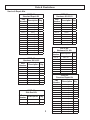
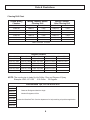
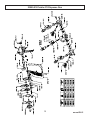
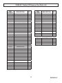
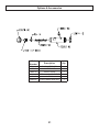
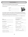
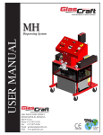
Probler P2
USER MANUAL
Dispense Gun
5845 WEST 82ND STREET
INDIANAPOLIS, INDIANA
46278 U.S.A.
Phone (317) 875-5592
Fax
(317) 875-5456
Email [email protected]
Web www.glascraft.com
Table Of Contents
Introduction
About This Manual.................................................................................................................................................... 1
Parts & Illustrations
Standard & Optional Equipment ............................................................................................................................... 2
Service & Repair Kits ............................................................................................................................................... 3
23950-XX Probler P2 Dispense Gun ....................................................................................................................... 5
Safety
Urethane Safe Handling and Use of Foam Equipment ............................................................................................ 7
Installation
How The Gun Works ................................................................................................................................................ 11
Fluid & Air Line Connection ...................................................................................................................................... 11
Installing The Probler P2 On Equipment Other Than Glascraft ................................................................................ 12
Operation
Pre operation Check List ........................................................................................................................................... 13
Operating Requirements ............................................................................................................................................13
Spray Technique ...................................................................................................................................................... 14
Maintenance
Checking For Leaks ..................................................................................................................................................
Daily Start-Up ...........................................................................................................................................................
Routine Care ............................................................................................................................................................
Piston Throw Adjustment ..........................................................................................................................................
15
16
17
17
Options
Options and Accessories .......................................................................................................................................... 20
Notes .......................................................................................................................................... 22
Limited Warranty Policy ........................................................................................................... 23
Technical Assistance ................................................................................................................ 24
For Your Reference ....................................................................................INSIDE BACK COVER
Introduction
About This Manual
Before operating, maintaining or servicing any
GlasCraft system, read and understand all of
the technical and safety literature provided with
GlasCraft products. If you do not have the proper or related manuals and safety literature for
your GlasCraft system, contact your GlasCraft
distributor or GlasCraft, Inc.
This manual provides information for the assembly, operation, maintenance and service of this
GlasCraft product as used in a typical configuration. While it lists standard specifications and
procedures, some deviations may be found.
In this GlasCraft technical and safety publication, the following advisories will be provided
where
appropriate:
NOTE
In order to provide our users with the most upto-date technology possible, we are constantly
seeking to improve products. If technological
change occurs after a product is on the market,
we will implement that technology in future production and, if practical, make it available to current users as a retrofit, up-date or supplement.
If you find some discrepancy between your unit
and the available documentation, contact your
GlasCraft distributor to resolve the difference.
GlasCraft, Inc. reserves the right to change or
modify this product as it deems necessary.
Is information about the procedure in progress.
CAUTION
Is imperative information about equipment
protection.
WARNING
Careful study and continued use of this manual
will provide a better understanding of the equipment and process, resulting in more efficient
operation, longer trouble-free service and faster,
easier troubleshooting.
Is imperative information about personal safety.
The information in this document is intended
only to indicate the components and their normal
working relationship typical use. Each assembly
should be directed by a GlasCraft distributor or
made from the GlasCraft assembly instructions
provided.
Parts & Illustrations
Standard Equipment
Part
Description
Number
23950-XX
Probler P2 Dispense Gun
GC-1386
User Manual
Optional Equipment
Part
Description
Number
23976-00
Flat Spray Kit
23983-01
Jet Stream Nozzle
23983-02
Jet Stream Nozzle
23984-00
Pour Adapter
23986-00
Static Mixer
Parts & Illustrations
Service & Repair Kits
23975-00
Standard Repair Kit
Part
Description Qty.
Number
7554-05
O-Ring
1
7554-06
O-Ring
7554-07
O-Ring
23979-00
Hardware Kit 00-03
Part
Description Qty.
Number
15845-00
3/16” Ball Driver
1
1
15845-01
5/32” Ball Driver
1
2
17672-00
Pin Vise
1
7554-09
O-Ring
2
23971-00
Screen Filter
2
7554-10
O-Ring
1
14693-17
Drill Bit
1
7554-16
O-Ring
3
14963-13
Drill Bit
1
7554-25
O-Ring
1
14963-14
Drill Bit
1
7554-26
O-Ring
1
14963-15
Drill Bit
1
7554-27
O-Ring
1
23974-12
O-Ring
1
7554-29
O-Ring
1
23974-07
O-Ring
2
7554-43
O-Ring
1
13867-08
O-Ring
2
13867-11
O-Ring
2
23974-07
O-Ring
2
23974-12
O-Ring
1
23979-AA
Hardware Kit -AA
Part
Description Qty.
Number
14963-28
23980-00
Hardware Kit 04-05
Part
Description Qty.
Number
DRILL BIT
1
14963-29
DRILL BIT
1
15845-00
BALL DRIVER
1
15845-01
BALL DRIVER
1
17672-00
VISE PIN
1
2
15845-00
3/16” Ball Driver
1
23971-00
FILTER SCREEN
15845-01
5/32” Ball Driver
1
23974-07
O-RING
2
23974-12
O-RING
1
17672-00
Pin Vise
1
23971-00
Screen Filter
2
14693-19
Drill Bit
1
14963-20
Drill Bit
1
23974-12
O-Ring
1
23974-07
O-Ring
2
23981-00
Premium Repair Kit
Part
Description Qty.
Number
23978-00
Side Seal Kit
Part
Number
Description
23973-00
SST Side Seal
2
23974-07
O-Ring
2
Qty.
23974-05
O-Ring
1
23974-06
O-Ring
1
23974-07
O-Ring
4
23974-08
O-Ring
2
23974-09
O-Ring
2
23974-10
O-Ring
1
23974-11
O-Ring
2
23974-12
O-Ring
1
23974-16
O-Ring
3
23974-25
O-Ring
1
23974-26
O-Ring
1
23974-27
O-Ring
1
23974-29
O-Ring
1
23974-43
O-Ring
1
Parts & Illustrations
Cleaning Drill Chart
Round Mixing
Chamber
Mixing Chamber Nozzle
Cleaning Drill
Mixing Chamber
Hole Cleaning Drill
23960-AA
14963-16
0.042
14963-21
0.0292
23960-00
14963-17
0.052
14963-24
0.035
23960-01
14963-11
0.057
14963-16
0.042
23960-02
14963-12
0.071
14963-17
0.052
23960-03
14963-15
0.086
14963-13
0.059
23960-04
14963-19
0.094
14963-14
0.07
23960-05
14963-20
0.116
14963-15
0.086
DRILL PIN VISE 17672-00
Tungsten Carbide
LPA2-147-1525
LPA2-147-2340
LPA2-147-3625
LPA2-147-5250
LPA2-147-7265
LPA2-147-1540
LPA2-147-2350
LPA2-147-3640
LPA2-147-5265
LPA2-147-7640
LPA2-147-1840
LPA2-147-2640
LPA2-147-3650
LPA2-147-6240
LPA2-147-7650
LPA2-147-1850
LPA2-147-2650
LPA2-147-4325
LPA2-147-6250
LPA2-147-2125
LPA2-147-3125
LPA2-147-4340
LPA2-147-6265
LPA2-147-2140
LPA2-147-3140
LPA2-147-4350
LPA2-147-7240
LPA2-147-2150
LPA2-147-3150
LPA2-147-5240
LPA2-147-7250
NOTE: The nozzle size is stated by the Orifice, Size, and Degree of Spray.
Example: LPA2-147-1525 .015 Orifice 25 Degrees
Non Atomized Tips, For use w/23976-00
23047-J1
23047-J2
23047-J3
23047-M1
23047-M2
23047-M3
23047-P1
.
Character Designates Machine Angle
.
Number Designates Orifice
Contact the GlasCraft Tech. Service department for help matching a tip with an application.
23047-P2
23047-P3
23950-XX Probler P2 Dispense Gun
REVISION C
23950-XX Probler P2 Dispense Gun Parts List
PART
NUMBER
PART
NUMBER
DESCRIPTION
1
7554-16
O-RING
3
2
7554-25
O-RING
1
PROBLER TRIGGER
1
7554-26
O-RING
1
COMPRESSION SPRING
1
7554-27
O-RING
1
O-RING
1
DESCRIPTION
QTY.
PG-13
FITTING
PG-15-01
2-WAY BALL VALVE
PG-18
PG-19
QTY.
13867-08
O-RING
2
7554-29
13867-11
O-RING
2
7554-43
O-RING
1
16832-00
AIR SWITCH ASSEMBLY
1
7704-08C
SET SCREW
1
17259-16F
MACHINE SCREW
1
7716-06C
SET SCREW
11
18383-02
1/4 DIA BALL
3
8212-12F
MACHINE SCREW
2
19881-00
PLUG FITTING
1
8301-12C
MACHINE SCREW
1
2253-04
LUBE FITTING
1
8462-08
FITTING
2
23951-00
1-3/8” AIR PISTON
1
8560-23
FITTING
1
23952-00
1-1/2” AIR PISTON
1
9869-19
SHOULDER SCREW
1
23953-00
CYLINDER SPACER
1
9936-20F
SET SCREW
1
23954-00
VALVE INSERT
1
9944-16C
MACHINE SCREW
4
23955-00
ISO SIDE BLOCK
1
23956-00
POLY SIDE BLOCK
1
23957-00
CHECK VALVE FILTER
2
23958-00
SEAL
2
23959-00
SEAL HOUSING
2
23961-00
FRONT TIP
1
23962-00
HANDLE
1
23963-00
PROBLER P2 HEAD
1
23964-00
GUARD
1
23965-00
TRIGGER PISTON
1
23966-00
REAR CAP
1
23967-00
TRIGGER PLUG
1
23968-00
RETAINING RING
1
23969-00
SPRING
3
23970-00
SPRING
2
23971-00
FILTER SCREEN
2
23973-00
SEAL
2
23974-07
O-RING
2
23974-12
O-RING
1
7554-05
O-RING
1
7554-06
O-RING
1
7554-07
O-RING
1
7554-10
O-RING
1
16832-00 AIR SWITCH ASSY. QTY.
7554-07
O-RING
1
7554-09
O-RING
2
16830-00
AIR SWITCH TUBE
1
16831-00
AIR SWITCH SPOOL
1
REVISION C
SAFETY
Safe Handling And Use Of Urethane Foam
Equipment
Organic Peroxides and Dual Component Coatings. Local
codes and authorities also have standards to be followed
in the operation of your spraying equipment. Chemical
manufacturer’s recommendations should be obtained
and considered. Your insurance carrier will be helpful in
answering questions that arise in your development of
safe procedures.
Introduction
Any tool, if used improperly, can be dangerous. Safety
is ultimately the responsibility of those using the tool. In
like manner, safe operation of polyester processes is
the responsibility of those who use such processes and
those who operate the equipment. This manual outlines
procedures to be followed in conducting polyester operations safely.
Personnel Safety Equipment
GlasCraft recommends the following Personal Safety
Equipment for conducting safe operations of the Polyester Systems:
All personnel involved in dispensing operations should
read and understand this manual. It is most important
that equipment operators, maintenance, and supervisory personnel understand the requirements for safe
operation.
This manual cannot answer every circumstance; each
user should examine his own operation, develop his
own safety program and be assured that his equipment
operators follow correct procedures. GlasCraft hopes
that this manual is helpful to the user and recommends
that the precautions in this manual be included in any
such program.
GlasCraft recommends that the user consult the state
and local regulations established for all Safety equipment
listed.
Urethane foam systems are comprised of several different chemical compounds, some of which may be hazardous if improperly used.
1.
Handle chemicals safely.
2.
Provide adequate ventilation.
3.
Provide adequate safety equipment (gloves, respirators, safety glasses, protective clothing, etc.) for operators and all others working in areas where they may
be exposed to the chemicals or their vapors.
4.
Avoid operating equipment which has given any
indication of malfunction.
5.
Become fully acquainted with the equipment and
chemicals used.
Operating Safely
In operating urethane foam equipment safely, user should
make every effort to:
CAUTION
Particular caution must be taken with respect to the
vapors released during the use of urethane foam systems.
Isocyanate compounds are used in urethane foaming
operations. The medical history of persons who may be
exposed to such isocyanates should be examined. It is
recommended that individuals with a history of chronic
respiratory ailments should avoid exposure to all isocyanates.
Handling Chemicals Safely
Storage of polyisocyanates, diamines, and organic solvents should be isolated and restricted to specially constructed storage rooms. Store chemicals in original containers and according to manufacturer’s recommendations
listed on the container. Maximum ambient temperatures
to which such chemicals should be exposed are specified
by the manufacturer and MUST NOT be exceeded either
in the storage area or in the spraying or pouring area.
In addition to the manual, GlasCraft recommends that
the user consult the regulations established under the
Occupational Safety & Health Act (OSHA), particularly
the following sections:
•
•
•
1910.94 Pertaining to ventilation.
1910.106 Pertaining to flammable liquids.
1910.107 Pertaining to spray finishing opera
tions, particularly Paragraph (m)
SAFETY
3.
Equipment capable of withstanding pressure. When HHC solvents contact aluminum or galvanized parts inside a closed container, such as a pump,
spray gun, or fluid handling system, the chemical reaction can, over time, result in a build-up of heat and pressure, which can reach explosive proportions.
To avoid moisture contamination, do not open containers until ready for use. After use, the remaining material
should be re-sealed in the original container and stored in
areas away from moisture.
During clean-up of spilled isocyanate component, respirators, gloves and eye protection must be worn. Isocyanates
which have been spilled can be controlled by covering
them with dry sawdust and/or other absorbent, inert materials. Care should be taken to avoid skin contact. The absorbent material and the absorbed isocyanate should be
collected promptly, placed in an open-top container, and
treated with dilute solutions of ammonium hydroxide and/
or alcohol. While being treated in this manner, the material
should be in an adequately ventilated area. Clothing on
which any material has been spilled should be removed
immediately, and cleaned before being worn again.
When all three elements are present, the result can be
an extremely violent explosion. The reaction can be
sustained with very little aluminum or galvanized metal:
any amount of aluminum is too much.
The reaction is unpredictable. Prior use of an HHC
solvent without incident (corrosion or explosion) does
NOT mean that such use is safe. These solvents can
be dangerous alone (as a clean-up or flushing agent) or
when used as a component of a coating material. There
is no known inhibitor that is effective under all circumstances. Furthermore, the mixing of HHC solvents with
other materials or solvents, such as MEK, alcohol, and
toluene, may render the inhibitors ineffective.
Clean-Up Solvents
WARNING
A hazardous situation may be present in your pressurized
fluid system!
The use of reclaimed solvents is particularly hazardous.
Reclaimers may not add any inhibitors, or may add
incorrect amounts of inhibitors, or may add improper
types of inhibitors. Also, the possible presence of water
in reclaimed solvents could feed the reaction.
Halogenated Hydrocarbon Solvents can cause an explosion when used with aluminum or galvanized components
in a closed (pressurized) fluid system (pumps, heaters, filters, valves, spray guns, tanks, etc.).
Anodized or other oxide coatings cannot be relied upon
to prevent the explosive reaction. Such coatings can be
worn, cracked, scratched, or too thin to prevent contact.
There is no known way to make oxide coatings or to
employ aluminum alloys, which will safely prevent the
chemical reaction under all circumstances.
The explosion could cause serious injury, death and/or
substantial property damage.
Cleaning agents, coatings, paints, etc. may contain Halogenated Hydrocarbon Solvents.
Several solvent suppliers have recently begun promoting HHC solvents for use in coating systems. The
increasing use of HHC solvents is increasing the risk.
Because of their exemption from many State Implementation Plans as Volatile Organic Compounds (VOC’s),
their low flammability hazard, and their not being classified as toxic or carcinogenic substances, HHC solvents
are very desirable in many respects.
Some GlasCraft spray equipment includes aluminum or
galvanized components and will be affected by
Halogenated Hydrocarbon Solvents.
There are three key elements to the Halogenated Hydrocarbon (HHC) solvent hazard.
1.
The presence of HHC solvents. 1,1,1-Trichloro
ethane and Methylene Chloride are the most common of
these solvents. However, other HHC solvents are suspect
if used; either as part of paint or adhesives formulation, or
for clean-up or flushing.
2.
Aluminum or Galvanized Parts. Most handling
equipment contains these elements. In contact with these
metals, HHC solvents could generate a corrosive reaction
of a catalytic nature.
SAFETY
WARNING
Adequate ventilation (as covered in OSHA Section
1910.94 and NFPA No. 91) is important wherever solvents are stored or used, to minimize, confine and exhaust the solvent vapors.
If you are now using Halogenated Hydrocarbon solvents
in pressurized fluid systems having aluminum or galvanized wetted parts,
IMMEDIATELY TAKE THE FOLLOWING STEPS:
•
Empty system, shut-off, completely depressurize in accordance with equipment service instructions.
•
Remove equipment from service, disassemble
in accordance with equipment servicing instructions.
•
Inspect all parts for corrosion and/or wear. Replace any damaged parts.
•
Thoroughly clean all parts of the equipment with
a non-halogenated solvent and reassemble in accordance with equipment servicing instructions.
•
Flush equipment with non-halogenated solvent.
•
Do NOT reuse equipment with HHC solvents or
with materials containing such solvents.
•
Material suppliers and/or container labels should
be consulted to ensure that the solvents used are compatible with your equipment.
Solvents should be handled in accordance with OSHA
Section 1910.106 and 1910.107.
Toxicity of Chemicals
GlasCraft recommends that you consult OSHA Sections
1910.94, 1910.106, 1910.107 and NFPA No. 33, Chapter
14, and NFPA No. 91.
Contact your chemical supplier(s) and determine the toxicity of the various chemicals used, as well as the best
methods to prevent injury, irritation and danger to personnel.
Also determine the best methods of first aid treatment for
each chemical used in your plan
NOTE
First Aid
If chemicals containing isocyanate are splashed on the
skin, they can produce ill effects. Steps to counteract
such effects should be started immediately.
TAKE IMMEDIATE ACTION...
Halogenated Hydrocarbon solvents are dangerous
when used with aluminum components in a closed fluid
system.
Apply Tincture of Green Soap, full strength, to the contaminated area. If Tincture of Green Soap is not immediately available, wash the exposed area repeatedly with
soap and water. Soap and water is not as desirable as
using Tincture of Green Soap because many isocyanate
components are not easily dissolved in water. In addition,
soap and water does not form a barrier to the isocyanate.
GlasCraft is aware of NO stabilizers available to prevent
Halogenated Hydrocarbon solvents from reaction under
all conditions with aluminum components in a closed
fluid system.
Consult your material supplier to determine whether your
solvent or coating contains Halogenated Hydrocarbon
Solvents.
After approximately two to four minutes, wash off the
Tincture of Green Soap with water. If there is still an indication of isocyanate present, repeat the application. If the
isocyanate contamination is on the facial area, care must
be taken to avoid getting the Tincture of Green Soap in
the eyes.
GlasCraft recommends that you contact your solvent
supplier regarding the best non-flammable clean-up solvent with the heat toxicity for your application.
If, however, you find it necessary to use flammable
solvents, they must be kept in approved, electrically
grounded containers.
If the person develops breathing difficulties, oxygen
should be administered. Quite often the exposed person
will experience residual effects such as coughing spells.
CONTACT PHYSICIAN IMMEDIATELY.
Bulk solvent should be stored in a well-ventilated, separate building, 50 feet away from your main plant.
WARNING
Contact a doctor immediately in the event of an injury
and give him the information you have collected. If your
information includes first aid instructions, administer first
aid immediately while you are contacting the doctor.
You should allow only enough solvent for one day’s use
in your laminating area.
“NO SMOKING” signs must be posted and observed in
all areas of storage or where solvents and other
flammable materials are used.
SAFETY
If a person accidentally swallows isocyanate, large
amounts of water should be swallowed immediately.
Vomiting should then be induced by patient sticking his
finger down his throat, or by swallowing large quantities
of warm salt water or warm soapy water. After vomiting,
more water should be taken to dilute isocyanate further.
CONTACT PHYSICIAN IMMEDIATELY.
In industrial and contractor applications, it is advisable
to run frequent tests to determine the exact concentration of isocyanate vapor in the air. Industrial equipment
is available for making such determinations. Your chemical supplier can recommend such equipment and procedures.
Proper Safety Equipment
All persons spraying or working is areas where forced
air ventilation is not adequate to remove isocyanate vapors from the air MUST use an approved (U.S. Bureau
of Mines) fresh air supplied respirator.
Ventilation
WARNING
Hazardous concentrations of some chemical vapors exist before they can be smelled. Chemical component
suppliers should be contacted to determine at what
concentrations the vapors of the chemicals they supply
become dangerous, and the procedures and equipment
needed to detect such dangerous concentrations. Such
equipment should be obtained.
Respirators should be regularly inspected, cleaned and
disinfected according to good practices. Records must
be kept of the inspections. The user MUST have a medical clearance indicating that he can safely use a respirator.
Adequate ventilation must be provided in any area where
foam chemicals are sprayed or poured, and wherever
the material containers are opened.
Respirators must fit securely; beards prevent a tight seal
around the face. Eye glasses have to be given special
attention and contact lenses are prohibited.
In industrial applications, foaming operations should be
restricted to specific areas, and proper ventilation should
be provided in these areas to prevent chemical vapors
from spreading. Spray foaming operations MUST be restricted to a spray booth where a minimum exhaust of
100 feet per minute at the face of the booth is provided.
Special care should be taken to prevent unsuspecting
personnel both inside and outside of the plant from being exposed to chemical vapors. The chemical vapors
should be exhausted to atmosphere in such a manner
and at a sufficiently low concentration that personnel
outside the plant are not exposed to dangerous concentrations of chemical vapors. Refer to OSHA Standards,
sub-part G, 1910.107 and particularly sub-section (m)
for Federal standards. State and local authorities may
have applicable statutes or regulations concerning ventilation.
Safety goggles, gloves and other protective devices are
suggested for operators of foaming equipment. Refer to
OSHA Standards, sub-part 1, 1910.132, 1910.133 and
1910.134 for Federal standards.
IF YOU HAVE ANY QUESTIONS REGARDING THE
ABOVE PRECAUTIONS OR ANY SERVICE OR OPERATION PROCEDURES, CALL YOUR GLASCRAFT
DISTRIBUTOR OR GLASCRAFT, INC.
NOTICE
All statements, information and data given herein are
believed to be accurate and reliable but are presented
without guaranty, warranty or responsibility of any kind
expressed or implied. The user should not assume that
all safety measures are indicated or that other measures
are not required.
In contractor applications (for example, at a construction
site, inside building or other enclosed space), the forced
ventilation normally provided is likely to be inadequate.
These applications, therefore, usually REQUIRE the use
of forced, fresh air respirators for all persons in the areas
where foaming operations are conducted or where the
chemical vapors are likely to spread.
5845 WEST 82nd STREET, SUITE 102
INDIANAPOLIS, INDIANA 46278 U.S.A.
PHONE (317) 875-5592
10
FAX (317) 875-5456
Installation
How The Gun Works
GlasCraft Equipment
The trigger actuates a small valve in the gun handle
that controls the flow of air into the piston assembly.
When the trigger is pulled, air flows through the valve to
the front of the piston. Air pressures force the piston towards the rear of the gun, simultaneously closing off
the purge air and moving the mixing chamber to a
position where the mixing chamber orifices are aligned
with the orifices in both, the side block seal and
check valve assemblies.
All GCI OEM fittings are as follows:
A SIDE - # 6 JIC
Hoses – Female Swivel Fitting
System and Gun – Male Fitting
B SIDE - # 6 SAE
Hoses – Female Swivel Fitting
System and Gun – Male Fitting
Air Hose is ¼” NPS
JIC and SAE Fittings DO NOT require the use of teflon
tape.
NOTE
The proper alignment of the orifices is determined by
the setting of the Set Screw, p/n 17259-16F, located
at the rear of the piston assembly. This set screw
determines the length of travel of the air piston and
has been preset at the factory and should not require
adjustment. (SEE MAINTENANCE SECTION)
Once the fittings are attached and tight, refer to system manuals for start-up instructions.
The two fluids (isocyanate and polyol) then flow thru
the material shut-off valves, seal, and check valve
assemblies and into the mixing chamber. The two
fluids impinge against one another and exit the
mixing chamber in a swirling, conical spray pattern.
When the trigger is released, the mixing chamber
returns to its original position and purge air flows into
the Mixing chamber housing, p/n 23963-00. The front
tip o-ring, p/n 23974-00 keeps air purge inside the
Gun Head, p/n 23963-00, forcing all of the air through
the orifices in the mixing chamber, for a complete, total
and constant purge.
This purge air continues to flow thru the mixing chamber
until the air switch, p/n 16832-00 is pulled up to shut-off
all air to the gun; or until the trigger is pulled again.
11
Installation
Installing P2 on Equipment other
than GlasCraft
3. Install the original fittings into PG-15-01 valves.
WARNING
It is recommended to use a non-permanent thread lock on
the 1/8 in. NPT threads to assist as a sealant and keep the
fittings from twisting with gun movement.
Do not place any part of the body in the path of the
material spray.
Do not point the gun at or near other personnel.
Do not look into the mixing chamber orifice at any time.
Because of the hazardous materials used in this
equipment, it is recommended that the operator use an
air mask, goggles, protective clothing, and other
safety equipment as prescribed by current regulations,
recommendations of the chemical suppliers, and the
laws in the area where the equipment is being used.
NOTE
4. Install the gun on the original Hoses.
The air slide valve, p/n 16832-00 is a ¼ in. NPSM.
WARNING
Relieve ALL system fluid and air pressures according to
manufacturer’s instructions.
If original equipment does not require the use of an unheated whip hose or isolation hose, the P2 can be
directly installed on to the material hose.
1. Remove the fittings from the original gun, typically
these fittings are 1/8 in. NPT male.
2. Remove GCI fittings, p/n’s 8560-23,PG-13 from
PG-15-01 ball valves. GCI ball valves are 1/8 in.
NPT female.
12
Operation
NOTE
Refer to specific system user manuals for complete
system installation.
Pre operation Checklist
Check that all fittings are tight and air regulators are
turned to “zero pressure”.
WARNING
Do not place any part of the body in the path of the
material spray.
Do not point the gun at or near other personnel.
Do not look into the mixing chamber orifice at any time.
Because of the hazardous materials used in this
equipment, it is recommended that the operator use an
air mask, goggles, protective clothing, and other safety
equipment as prescribed by current regulations, recommendations of the chemical suppliers, and the laws in
the area where the equipment is being used.
WARNING
If purge air is to be turned OFF, BOTH MATERIAL SHUTOFF VALVES, p/n PG-15-01, MUST BE TURNED TO THEIR
“OFF” POSITION BEFORE TURNING “OFF” THE PURGE
AIR !
Failure to follow this procedure will possibly result in the gun
head becoming encased with mixed product.
For proper purging following use, the air switch must be left
OPEN for at least 15 SECONDS after the trigger has been
released.
The flow of material into the mixing chamber is controlled by
the ON or OFF position of the two material shut-off valves.
NOTE
Both material shut-off valves must be FULLY OPEN during
dispensing and must be FULLY CLOSED during service or
extended shut-down periods.
WARNING
Operating Requirements
•
8 - 10 CFM at 90 -110 PSI
•
MAXIMUM Static Fluid Pressure - 3200 PSI
BOTH MATERIAL SHUT-OFF VALVES, p/n PG-15-01,
MUST BE TURNED TO THEIR “OFF” POSITION BEFORE
REMOVING SCREWS, P/N 9944-16C!!
Failure to follow this procedure will possibly result in the gun
head becoming encased with mixed product.
WARNING
The GlasCraft Probler P2 Gun is designed and manufactured to operate at a maximum static fluid pressure
not to exceed 3200 psi. When attached to a GlasCraft
proportioning system, this pressure will not be exceeded. However, if the GlasCraft Probler P2 Gun is installed on any other manufacturer’s self-designed equipment, great care must be taken to ensure that the maximum static fluid pressure not be exceeded.
NOTE
If the gun is being used for short periods of
spraying, GlasCraft recommends that the purge air be
left ON.
The material shut-off valves, p/n PG-15-01 can be left
in the OPEN position during these periods of time.
ON OFF
Refer to system manuals for start-up and
shut-down procedures.
13
Operation
Spray Technique
Always operate safely and follow all safety procedures
outlined.
Higher pressures and temperatures may be used to
increase material break-up, improve mixing and speed
rise times. With hose lengths over 50 ft., or when material viscosities are high, higher material pump pressures
may be necessary.
To achieve the optimum spray pattern for each application, the appropriate mixing chambers are available in
six round and six flat spray sizes. Hardened mixing
chambers are also available (see mixing chamber
chart).
The gun air switch assembly MUST BE OPENED
(down position) prior to spraying to provide air for trigger
operation and purge air when the trigger is released.
The standard mixing chamber supplied with your gun
will be adequate for all but the smallest and largest
applications.
When spraying, the gun trigger may be depressed continuously, or triggered at the end of each stroke. A
smooth, even layer is best achieved by moving the
Foam rise and cure times will vary according to the
material and substrate temperature. Higher material or
substrate temperature will increase rise and cure times;
lower material or substrate temperatures will decrease
rise and cure times. Consult your chemical manufacturer’s data specification sheets for their recommended
spray temperatures. Under most circumstances, both
components will be used at identical temperatures.
Gun back and forth in a slow, even motion, overlapping
the previous pass about 50 to 75 percent. DO NOT
SPRAY OVER RISING FOAM! The ideal gun-to-surface
distance is about 18 to 24 inches. Be sure to point the
gun directly at the surface to be sprayed. Spraying at
an angle to the surface will cause the foam to be rough
and will generate overspray.
14
Maintenance
WARNING
Before attempting to perform any maintenance on
this gun,relieve All Fluid and Air Pressures!
2. Check the material valves, p/n PG-15-01 for any leaks:
• Turn OFF both material valves.
• To relieve fluid and air pressures:
• Turn OFF all air supplies at system except gun
trigger air.
• Trigger the gun until all fluid pressures have been
relieved.
• Turn OFF the gun trigger air at the system.
• Trigger the gun until all trigger air pressure has been
relieved.
Perform Gun maintenance as follows:
1. Check for leaking Seals, p/n 23973-00:
• Turn OFF the gun incoming air by closing gun air
switch.
• Trigger the gun several times.
• Turn OFF the gun incoming air by closing the air
switch.
• Trigger the gun several times.
• If additional material is purged, the material valves
are leaking.
• Correct the leaks by taking off black knobs and turning
packing 1/8 in. to 1/4 in. turns at a time until the leak
has stopped. Re-check.
• Wait approximately 10 - 20 seconds, then turn ON
3. Check Side Blocks
the incoming air by opening Gun Air Switch.
• Repeat two or three times.
• If any material has been purged from the gun, the
• Turn OFF the air switch on the gun.
WARNING
seals, p/n 23973-00 are leaking, or o-ring,
p/n 23974-07
Before removing the side blocks make certain that both
material valves are in the OFF positions!
re-checking.
If the material valves are on when the side blocks are
removed the gun will quickly become encased in urethane!
• Correct leaks by replacing the seals or o-rings and
WARNING
Point gun side blocks down, away from all personnel.
Existing fluid pressures could cause material to exit the
side blocks with considerable force.
15
Maintenance
• Take the Side Blocks off by removing screws,
p/n 9944-16C.
• Use correct size drill bit to clean out the mixing chamber exit passage. Use correct size drill bit to clean the
inlet side holes of the mixing chamber taking care not
to scratch the mixing chamber’s polished surfaces.
(refer to the chart at front of manual)
• Examine the sides of the mixing chamber, p/n 23960for scratches and/or material build-up. Carefully,
without scratching the seal surfaces (sides), remove
any accumulated material. Solvent can be used to
wash accumulated material off of chamber, side blocks,
etc. Keep the gun Chamber tilted toward the ground so
that solvent does not run back into gun. Certain
solvents will attack o-rings on chamber shaft
causing swelling and deterioration of o-rings.
• Re-assemble the side blocks and tighten the screws.
Grease should appear at the tip of the Mixing Chamber.
NOTE
• Place generous amounts of high quality, white lithium
grease in each side of the gun front housing and on
the side block seals.
DO NOT open the air switch on the gun because this
will purge grease from the Gun. The grease should be
allowed to remain in the gun overnight.
16
Maintenance
Daily Shut-Down
For experienced users
4. Inject white lithium grease into zerk fitting until a
light mist of grease is purged through the snout.
Shut off the air purge.
Once you have used the gun with a product and system,
and you have become comfortable with techniques on
how all the variables are affecting your operations and
maintenance requirements, Daily, Weekly, and
Monthly Maintenance requirements can be addressed
specific to your operation.
1. Turn the ball valves off, p/n PG-15-01, activate and
deactivate the gun 5 - 6 times to purge residual
pressure.
Zerk Fitting
5. Remove the air cap, p/n 23961-00 and set to side.
If solvent soaking is required, remove the o-ring,
p/n 23974-12 before soaking.
6. Remove the insert, p/n 23977-XX and soak in
solvent until next usage.
2. Drill out the chamber insert snout with correct size
drill bit for insert. (see chart in front of manual)
3. Pull slide valve, p/n 16832-00 halfway back to limit
the air purge.
Daily Start-Up
Air Switch
1. Clean the snout insert, p/n 23977-XX. Be sure both,
the face and bottom flat are Clean. Drill the snout bore
out with the correct size bit for Snout. (see chart in
front of manual)
2. Clean the inner bore of the chamber. Drill out the chamber snout inlet bore as required.
3. Install the snout insert.
4. Install the air cap, p/n 23961-00 on to the chamber.
17
Tighten finger tight until the cap bottoms out. Snug down
with a ½ in. wrench. This does not require high torque.
Over tightening can result in chamber damage.
Maintenance
NOTE
Routine Care
Parts Replacement Procedure
Before attempting to perform any maintenance on this gun
OR before removing side blocks, make certain that both Gun
material valves are in the fully OFF positions!
Refer to specific system user manuals for complete
system installation.
WARNING
Before attempting to perform any maintenance on this
gun OR before removing the side blocks, make certain
that both gun material valves are in the OFF positions!
If the material valves are on when side blocks are
removed, the gun will quickly become encased in
urethane!
WARNING
If the material valves are on when side blocks are removed,
the gun will quickly become encased in urethane!
It is recommended that the following service be performed
on a daily basis.
1. Clean the gun using a brush and an appropriate clean
solvent.
1. Read each procedure entirely before beginning and
2. Inspect the side block seals, p/n 23973-00, making certain they are clean and free of scratches, nicks or foreign material. Clean and replace as required.
refer to the illustrations as needed.
2. Flush and clean all chambers and passages as they
become accessible.
3. Remove, clean or replace the filter screen,
p/n 23971-00.
4. Maintain a reasonable stock level of “wear” items such
as seals and o-rings. (see Service & Repair Parts Kits
listed in Parts & Illustrations section.)
3. Clean all parts before assembly.
4. Replace all o-rings and seals with new parts from
the appropriate kit.
5. Inspect all parts for wear or damage and replace as
required with new genuine GlasCraft replacement
parts from your authorized GlasCraft distributor.
6. Inspect all threads for wear or damage and replace
as required.
7. Tighten all threaded parts securely, but not excessively, upon assembly.
Piston Throw Adjustment
The P2 gun piston throw is factory set and as a rule, should
not require adjustment. The piston throw refers to how far
back the air piston will travel when the gun is triggered.
Proper throw adjustment will align the mixing chamber side
ports with the side block seal thru port. There is a set screw
that determines how far the piston will travel before it stops.
To determine if the Throw is correct:
1. Turn the material ball valves, p/n PG-15-01 to the OFF
position.
8. Lightly lubricate all o-rings and threads with
lithium grease.
9. Check all springs for resilience. They should return
quickly to their original (new) length.
18
Maintenance
2. Trigger the gun to clear out residual pressure in Side
blocks.
6. Place seal / seal housing assembly into gun head so
the face of seal sets against the chamber. Look thru the
thru port of the Seal. The side port of the Chamber
should be at the center, or slightly forward of the center
line. If this adjustment appears to be correct, rotate the
seal housing to ensure the air cap, p/n 23961-00 is
not contacting the seal housing, p/n 23959-00. There
3. Remove the side blocks, p/n 23955-00 & 23956-00.
should be no contact between these two parts. Contact
will result in chamber damage.
7. Adjust the set screw, p/n 17259-16F until
a. The side port of the chamber is “on center” with or
forward of center of the thru port of seal.
b. The seal housing can be rotated and does not make
contact with the air cap.
4. Remove one of the side block seal housings,
p/n 23959-00 from side block. Leave the seal,
p/n 23973-00 in housing and rinse with suitable
solvent.
8. Turn the air ON and re trigger the gun, then shut the
air OFF before releasing trigger. Re-check the throw.
9. If the set screw feels loose, Remove it from the rear
cap, clean and apply non-permanent thread lock to
threads and reinstall, set adjustment.
5. Turn the air ON to gun, pull the trigger to actuate the
gun into spray position, when gun pulls back, keep
in mind the purge air will not shut off. Turn air OFF
at the slide valve, p/n 16832-00 before releasing
trigger.
19
Options & Accessories
20
Options & Accessories
Part
Number
Description
Qty.
PG-14
FLUID NOZZLE SEAL
1
18378-00
NOZZLE NUT
1
19881-00
PLUG FITTING
1
20634-01
SPIRAL MIXING ELEMENT
1
23974-12
O-RING
1
23985-00
STATIC MIXER ADAPTER
1
21
Notes
22
Limited Warranty Policy
GLASCRAFT, INC. (“GlasCraft”) warrants to the original Purchaser of GlasCraft manufactured equipment
and parts, that all GlasCraft manufactured equipment and parts will conform to their published written specifications and
be free of defects in workmanship and material for a period of one (1) year from the original date of installation. GlasCraft
makes no warranty to anyone other than the original Purchaser.
If any GlasCraft manufactured part or equipment is found to be defective in workmanship or material within the one-year
period from the date of installation, as determined solely by GlasCraft, GlasCraft, in its sole discretion, will either repair
or replace the defective part or equipment at GlasCraft’s cost, including freight charges both ways, or credit or refund the
purchase price for the defective equipment or part.
A warranty claim will be honored only when:
1. GlasCraft has been informed, in writing, of any such defect in workmanship or material within ten (10) days
after discovery by the original Purchaser;
2. An official of GlasCraft has issued a return authorization number; and
3. The claimed defective equipment or part has been returned to GlasCraft by the original Purchaser, freight
prepaid (with proper return authorization number(s) attached), to: GlasCraft, Inc., 5845 West 82nd Street,
Suite 102, Indianapolis, IN 46278, U.S.A.
This warranty shall not apply to any equipment or parts that have been altered or repaired by anyone other than GlasCraft
or to defects or damage resulting from improper installation, misuse, negligence, accident, or use not specified by
GlasCraft. This warranty shall not apply to any equipment where any parts or components were replaced by any parts
or components not manufactured or supplied by GlasCraft. The decision by GlasCraft shall be conclusive and binding
on Purchaser.
GlasCraft does not warrant that any equipment or parts sold to Purchaser meet or comply with any local, state, federal,
or other jurisdiction’s regulations or codes. GlasCraft does not warrant that any equipment or part sold to Purchaser,
when used individually or in concert with any other part, equipment, device, component or process, does not infringe on
any patent rights of any third party. GlasCraft only warrants that it has no specific knowledge of any such infringement.
GlasCraft makes no warranty as to any parts or equipment manufactured by others. Purchaser shall look solely and
only to the manufacturer of such parts or equipment with respect to any warranty claims. GlasCraft hereby assigns to
Purchaser the original manufacturer’s warranties to all such equipment and parts, to the full extent permitted.
THE AFORESAID WARRANTY IS IN LIEU OF ALL OTHER WARRANTIES, EXPRESS OR IMPLIED. SPECIFICALLY THERE ARE NO WARRANTIES OF MERCHANTABILITY OR FITNESS
FOR A PARTICULAR PURPOSE, WHICH WARRANTIES ARE SPECIFICALLY DISCLAIMED.
GlasCraft shall not be liable for any loss or expense resulting from damage or accidents caused by improper use or application of materials manufactured or sold by GlasCraft or its distributors or agents.
UNDER NO CIRCUMSTANCES SHALL GLASCRAFT’S LIABILITY EXCEED THE AMOUNT PURCHASER PAID FOR THE CLAIMED DEFECTIVE EQUIPMENT OR PART. UNDER NO CIRCUMSTANCES SHALL GLASCRAFT BE LIABLE FOR INCIDENTAL OR CONSEQUENTIAL DAMAGES OR FOR LOST PROFITS.
No action arising from or relating to any goods manufactured by or purchased from GlasCraft may be brought more than
one (1) year after the cause of action accrues.
23
Technical Assistance............
Thank You for selecting GlasCraft spray equipment
Should you have any questions or need technical assistance, contact your factory authorized
GlasCraft distributor.
Distributor: _________________________
Phone: ____________________________
Contact: ___________________________
For any issues your distributor cannot address, the GlasCraft technical service department is
always available to assist you with the operation of your spray equipment. To help our technical
representatives expedite your call and better address your questions, please have the following
information ready and available when you phone GlasCraft.
* If your questions are not urgent, You can e-mail all correspondence to [email protected]
For Air Powered Systems:
Model: _____________________________
Serial number: _______________________
Air compressor size: __________________
CFM generated: _____________________
Type of spray gun: ____________________
Serial number: _______________________
Pressure at the system:
Is your equipment:
Dynamic fluid pressure:
Single phase: _______ Three phase ______
ISO __________ POLY ___________
What is the inbound voltage
to your equipment: ____________________
Spray gun chamber size: ______________
Hydraulic ________ Pneumatic _________
Material being sprayed: _______________
Temperature setting ISO: _______________
Viscosity: ISO _________ POLY ________
Temperature setting POLY: ______________
Approximate material temperature: ______
Temperature setting HOSE: _____________
24
For Your Reference
Date Purchased
__________________________________________________
Distributor
______________________________________________________
______________________________________________________
Contact
______________________________________________________
Phone
______________________________________________________
E-mail
______________________________________________________
GlasCraft manufactures a complete line of polyurethane foam and polyurea coating spray systems.
If your application is in-plant or a field contractor - GlasCraft has a system package to meet your
requirements.
GUARDIAN - AIR POWERED / A5 & A6 SERIES EQUIPMENT
. 6000 OR 12000 WATTS OF HEAT
. 1600, 2200, OR 3000 PRESSURE SET-UPS AVAILABLE
MH, MH II, & MH III HYDRAULIC POWERED SYSTEMS
. UP TO 45 LBS / MINUTE OUTPUT
. EXCELLENT PERFORMANCE AND RELIABILITY
GUARDIAN MMH - MOBILE MODULAR HYDRAULIC SYSTEMS
. SPECIFICALLY DESIGNED FOR ANY TYPE OF SPRAY RIG
. GIVE COMPLETE UTILIZATION OF FLOOR SPACE IN MOBILE RIG
PROBLER P2 SPRAY GUN
. IMPINGEMENT MIX / AIR PURGE
. OPTIONAL NOZZLE FOR SPRAYING STUD WALLS, POURING & STREAM JET
For more information concerning any of these GlasCraft products,
contact your local authorized GlasCraft distributor or visit www.glascraft.com
Quality and Performance…
GENUINE GLASCRAFT
www.glascraft.com
GC-1386
REVISION C
5845 WEST 82nd STREET
INDIANAPOLIS, INDIANA 46278
U.S.A.
Phone (317) 875-5592
Fax (317) 875-5456
[email protected]