1
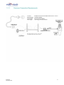
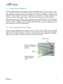
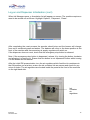
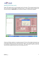
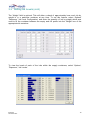
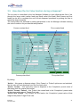
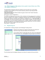
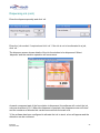
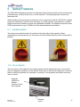
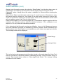
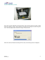
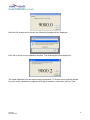
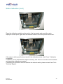
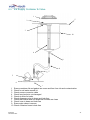
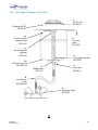
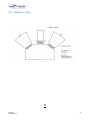
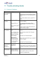
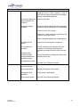
In k Dispe nsing System
ID S H P25
User Manual
IDS HP25
November 2007
VALE-TECH LIMITED
Unit 12, Depot Road, Newmarket, Suffolk CB8 0AL, UK
Tel: +44 (0) 1638 668583/668593
Fax: +44 (0) 1638 676720
E-mail: sales@vale -tech.co.uk
Introduction
This User Manual provides the user with a comprehensive guide to the machine.
The machine may be configured with 16, 20 or 24 ink containers, each with a maximum
capacity of 25kg. This comprises 16 containers within the main machine frame, with an
extension for each 4 additional containers.
The scale container ranges are 5kg, accommodating 1kg, 2.5kg and 5kg containers, or
30kg, accommodating 5kg, 10kg and 25kg containers.
The User Manual identifies the requirements for the initial installation of the machine and
continues to provide information for the effective operation of the machine on a day-to-day
basis including maintenance, to ensure a high standard of ink dispensing can be
consistently achieved.
The Service section of this manual enables the user to identify any spare parts that may
need to be ordered for the machine. This product has been manufactured to the highest
standards; however, should any difficulties arise, before requesting technical support, a
speedier resolution can usually be reached by referring to the trouble-shooting guide within
this section. A full set of drawings is also provided to assist in fault finding in the unlikely
event of the product developing a fault.
Full Ink Manager Software training is provided within the Training Manual to ensure that
the user can feel confident with the machine operation.
The Service Log at the back of this manual serves to provide contact information. Should
additional assistance be required please refer to the contact details supplied within this
section. Forms available in this section allow the service history of the machine to be
recorded for future reference.
IDS HP25
November 2007
2
Vale Tech IDS HP25
1
2
3
Introduction
2
Contents
3
Certificate of Conformity
6
Installation
7
1.1
Pre-Install Information
7
1.1.1 Services Connection Requirements
8
1.2
Positioning of Machine
9
1.3
Connecting Electrical Supply
9
1.4
Connecting Air Supply
10
1.5
Connecting the PC
11
IDS Start-Up Procedure
11
2.1
Switching On IDS
11
2.2
Log-on and Dispenser Initialisation
11
2.3
IDS Beacon Warning Indicator
13
IDS Ink Set-Up
14
3.1
Setting Ink Names
14
3.2
Loading Ink
15
3.3
Setting Ink Levels
16
3.4
Valve Configuration
20
3.5
How does the Ink Valve function during a dispense?
21
3.6
What happens if the same Ink is used in more than
one of the ink supply containers?
23
Dispensing Ink
23
3.7
IDS HP25
November 2007
3
Vale Tech IDS HP25
4
Hardware Settings
25
5
Safety Features
26
5.1
Isolator Switch
26
5.2
Door Switch
26
5.3
Emergency Stop Switch
27
5.4
Alarm Sounder
27
6
7
8
Ink supply container
28
6.1
Ink Supply Container Lids
28
6.2
Supply Container and Valve Air Regulator Adjustment
29
Balance Assembly
30
7.1
Using the Balance
31
7.2
Overweigh Protection
31
7.3
Scale Calibration
31
Cleaning & Maintenance
39
8.1
Dispense Valve Assembly
39
8.2
Carriage Assembly
40
8.3
Ink Supply Container & Valve
41
IDS HP25
November 2007
4
Vale Tech IDS HP25
SERVICE MANUAL
42
9
43
Spare Parts
9.1
External Parts
43
9.2
Ink Supply Container and Valve
44
9.3
Pneumatics and Electronics
45
9.4
Carriage Assembly
46
9.5
Dispense Valve
47
9.6
Ink Level Sensor
48
9.7
Parts List
49
10
Preventative Maintenance Programme
51
11
Trouble-shooting Guide
52
11.1
52
Common Problems.
12
PC Hardware Configuration
55
13
Ink Manager Hardware Configuration
56
14
Drawings
57
TRAINING MANUAL
58
15
59
Ink Manager Software
SERVICE LOG
60
16
Introduction
61
16.1
61
17
Contact Information
Service History
62
17.1
62
IDS HP25
November 2007
Machine Fault/Maintenance Log
5
Declaration of C onf ormity & Qualit y
Vale-Tech Limited Hereby Declares That
Machine:
Project:
Is in conformity with the provisions of the machinery directives as listed below: The Machinery Directive, 98/37/EC – “Machinery is described in the Directive as "an assembly of
linked parts or components, at least one of which moves, with the appropriate actuators, control
and power circuits, etc., joined together for a specific application, in particular for the processing,
treatment, moving or packaging of a material". The manufacturer is responsible for verifying
whether a particular product falls within the scope of the Machinery Directive.”
The Pressure Equipment Directive, 97/23/EC – “ The directive provides control over equipment
subject to pressure” Pressure equipment being vessels, piping, safety accessories and pressure
accessories. A pressure assembly being several pieces of pressure equipment assembled to form
an integrated functional whole.
The EMC Directive, 89/336/EEC – “The Directive applies to most electrical and electronic
apparatus, that is, finished products and systems that include electrical and electronic equipment.”
The Low Voltage Directive, 73/23/EEC – “Broadly the Regulations apply to most consumer,
commercial and industrial electrical equipment designed for use within the voltage ranges 50 V ac
to 1,000 V ac and 75 V dc to 1,500 V dc.”
Remarks & restrictions for this declaration
This declaration is no longer valid if any changes are made to the machine, which is not
corresponding to the abovementioned standards.
Place and date:
Newmarket
G Adlem:
Mechanical Engineering
C Stapleton:
Electrical Engineering
M Hughes:
Director
N Scott:
Director
Representing:
Vale-Tech Ltd
12 Depot Road
Newmarket
Suffolk CB8 0AL
United Kingdom
IDS HP25
November 2007
6
1
Inst allation
1.1 Pre-Install Information
IDS HP25
16-24 colour, 25kg dispenser
2185mm
1650
474mm
474mm
1400mm
474m
1650m
IDS HP25
November 2007
7
1.1.1
IDS HP25
November 2007
Services Connection Requirements
8
1.2 Positioning of Machine
The IDS HP25 comprises one primary module, measuring 1.6m (D) x 1.4m (W) x 1.65m
(H). It should be sited in its desired location by moving with a forklift or pallet truck,
remembering to ensure there is a requirement for a minimum of 300mm of clear space at
the rear of the machine for access to enable the connection of primary services, and
clearance at either side to gain access to the electrical and pneumatic supply cabinets.
After positioning the IDS HP25, ensure that all the feet are placed flat on the floor before
leveling. Correct leveling is achieved by placing a spirit level on all four corners and also
across the frame. Adjustment to the height of the IDS HP25 is done by adjusting each of
the corner feet up or down as necessary.
1.3 Connecting Electrical Supply
Connect mains electrical power rated at either 115V or 230V 50/60 Hz to the UPS
(Uninterruptible Power Supply) as illustrated, or inlet power socket mains input if no UPS is
fitted. This is located inside the machine on the right side and indicated as ‘POWER’.
Removal of side panel is required for access to these connections.
Power to PC
Main electrical power
supply from UPS to
machine
UPS
Mains electrical
power supply to
UPS
IDS HP25
November 2007
9
1.4 Connecting Air Supply
Connect an airline from an external filtered, clean, dry regulated air supply to the air input
connector. This is located on the air manifold assembly within the left side of the IDS
HP25. The air is connected via the quick-fit air coupling supplied by Vale -Tech and
requires 8mm hard walled hose for the push fitting. Alternatively, the air supply can also be
fitted using soft wall hose and a Jubilee Clip (Use Imp ½“ bore or Met 12.70mm, Imp ¾“ or
Met 19/20mm o/d air hose).
Air input
connection
Quick-fit Air Coupling
IDS HP25
November 2007
10
1.5 Connecting the PC
Connect the Keyboard and Monitor cables to the appropriate ports on the back of the PC
(refer to the configuration data in the service section). Now connect network, printer,
scanner and telephone modem connections to the PC, if additionally required.
Note: Before powering on the PC Please ensure that its Power Supply Unit is set to the
correct mains power voltage either 115V or 230V. Full range PSU’s are auto switching,
115/230V.
2
ID S H P25 St art-Up Procedure
2.1 Switching On IDS HP25
Before switching on the PC or IDS HP25 machine, make sure that the Ink containers
initially have their air valves turned OFF.
Now switch on the IDS HP25 by turning the mains ON/OFF isolator switch on the lower
right side of the machine CLOCKWISE to the ON position.
Now turn on the PC and the monitor. The PC is located at the lower right side at the front
of the machine, and the power button is accessible through the open panel. At this point,
the red light on the beacon will be illuminated and the alarm will be sounding.
2.2 Log-on and Dispenser Initialisation
Once the PC has powered up, launch the Ink Manager Software program and log on.
If there are no user accounts, create these by logging on as ‘administrator’ (password
supplied separately).
IDS HP25
November 2007
11
Log-on and Dispenser Initialisation (cont)
When Ink Manager opens, a formulation list will appear on screen. The machine requires a
reset to be carried out as follows. Highlight ‘Options’, ‘Dispenser’, ‘Reset’.
After completing the reset process the sounder should stop and the beacon will change
from red to combined green and amber. The balance will move to the home position at the
front of the machine and the secondary air supply regulator will switch on.
If the dispenser does not reset, check that the emergency stop button is released.
Note: If the emergency-stop button is depressed, release it by turning the button clockwise
and allowing it to spring out. Ensure that the button is not depressed further whilst turning
it or the button will not release.
After the initial IDS pressurisation, turn the air regulators which feed the ink containers to
the ON position one at a time, ensure the ink container lids are secure and check for any
minor air leaks. The air regulators are located inside the panel at the front of the machine
on the right hand side.
Ink
container
air
regulators
IDS HP25
November 2007
12
2.3 IDS Beacon Warning Indicator
RED: Indicates Emergency Stop
Switch activated or machine in
initial Power ON state.
AMBER: Indicates the balance
dispenser is moving.
GREEN AND AMBER: Indicates
machine in RESET condition or ready
to dispense.
GREEN: Indicates machine is in
the process of dispensing ink.
IDS HP25
November 2007
13
3
ID S H P25 In k Set-Up
3.1 Setting Ink Names
WARNING: DO NOT FILL THE INK SUPPLY CONTAINERS WITH INK UNTIL THIS STAGE HAS BEEN
COMPLETED!
The reference or description for each ink to be used must be allocated to each of the
supply containers to be filled. The corresponding ink will be put into the container later
when filling commences. Complete the Ink Reference names in the space provided below.
Some machines may have a pre-determined list setting out which ink should be placed in
which supply container. In this case, this information will be supplied in conjunction with
this manual or obtained from the distribution agent.
Container
Series/Reference/ /Colour
1.
2.
3.
4.
5.
6.
7.
8.
9.
10.
11.
12.
13.
14.
15.
16.
17.
18.
19.
20.
21.
22.
23.
24.
IDS HP25
November 2007
14
3.2 Loading Ink
WARNING: NEVER TRY TO REMOVE A SUPPLY CONTAINER LID WHILST UNDER
PRESSURE!
Turn the air valve for the container which is to be refilled to the OFF position. This allows
the container to fully vent (de-pressurise). When the pressure has reduced to enable the
lid to be removed, lift the lid handle, allow the lid to drop slightly from its location, tip and
turn 90 degrees and lift to remove from the ink supply container.
Each IDS HP25 ink container is pressure tested using water prior to shipment and so any
residual moisture should be fully removed before each container is filled with ink. Before
loading ink it may be advisable to clean out the containers with an alcohol/isopropranol
solution, taking care not to move or damage the level sensor probes attached to the side
of the container.
IDS HP25
November 2007
15
3.3 Setting Ink Levels
Ink level sensing is achieved by monitoring the levels in the individual containers using a
probe mounted on the inside of each container. The probe comprises 2 insulated steel
rods spaced 20mm apart. One side is electrically isolated from the container.
The probe is mounted vertically inside the container, with the end of the probe as close to
the bottom of the container as possible. The way in which the low level value is set
ensures that the ‘container empty’ point registers prior to the container actually becoming
empty. This eliminates air being drawn through to the dispense valve, and ink spitting from
the valve, which may happen if the container was to actually become completely empty.
The high level value is set with the ink below the top of the level sensor probe; keeping the
ink away from the lid and its sealing gasket, and well below the container air pressure inlet.
Figure 10 shows the diagram of the ink level probe and ink level indication within the ink
container.
To set the ink levels, select ‘Options’ ‘Dispenser’ ‘Valve Configuration’ from the drop down
menu in Ink Manager. Once this page opens, click on ‘Calibrate Main Tank Levels’ to open
the setting up option. The diagram below shows the ink level probe and ink level indication
within the ink container. To begin setting the ink levels, ensure the correct colour ink from
the Setting Ink Names list in 3.1 is selected, and pour in enough ink to cover approx 1inch,
(25mm) above the bottom of the level sensor probe in the container.
Level
Sensor
Full point
Empty Point
IDS HP25
November 2007
16
Setting Ink Levels (cont)
Select ‘Set Empty’ button to set the empty level for this colour. The numerical value for this
will be recorded in the box above ‘Set Empty’ button. This ensures that the container will
show the empty point BEFORE the ink reaches the bottom, as previously explained.
Continue to fill the container to a maximum level of 1/2 Inch (12mm) below the bend at top
of the probe. When this is done, click the ‘Set Full’ button. The numerical value for this will
be recorded in the box above the ‘Set Full’ button. The value shown in the box for the full
level should be smaller than the value of the empty point level.
IDS HP25
November 2007
17
Setting Ink Levels (cont)
Set Empty Indication
Set Full Indication
Note: The live value in the boxes ‘Set Empty Indication’ and ‘Set Full Indication’ will be
recorded into the selected container number (into either the full or empty points depending
on which button is ‘clicked’). Therefore, it is important to go through the filling of the ink
containers and the setting of the low and high level procedure in the correct sequence. If
the ‘Set Full’ button is clicked before the container is filled, the value indicated will be
stored as the full value. If the ‘Set Empty’ button is clicked when the ink container is full,
the machine will not dispense even though the container is full. This is due to the software
interpreting the signal sent from the Level Sensor Probe indicating that the container
requires re-filling.
IDS HP25
November 2007
18
3.3 Setting Ink Levels (cont)
The ‘Weight’ field is optional. This will allow a check of approximately how much ink by
weight is in a particular container at any time. To set this feature, select ‘Options’
‘Dispenser’ ‘Ink Level Configuration’ and enter the quantity of ink by weight which was
used to fill the container between the empty and full points into the ‘Weight’ box of the
appropriate ink container.
To view the levels of each of the inks within the supply containers, select ‘Options’,
‘Dispenser’, ‘Ink Levels’.
IDS HP25
November 2007
19
3.4 Valve Configuration
To allocate settings to each ink container, open the Valve Configuration settings. Select
‘Options’ ‘Dispenser ‘Valve Configuration’ from the drop down menu in Ink Manager. Each
container has its own ‘Folder tab’ and must be allocated the correct colour reference in the
‘Name’ field before the valves can be configured for their flow rates. For this information
please refer to the list in Setting Ink Names, in 3.1.
Before starting to dispense ink, the flow rate for each ink valve needs to be set in order to
provide swift but controlled dispensing. It is necessary to understand that the viscosity and
flow attributes of the ink will affect its actual dispense rate. The ink container regulator has
been set at 16psi, (1bar).
There is a facility to split the dispense process into stages, for ease of control. These are
‘coarse’ feed for the bulk of the dispense down to approximately 100g before completion,
‘coarse pulsed’ feed giving coarse feed control down to approximately 20g before
completion, ‘fine continuous’ feed down to approximately 10g before completion and
finally, ‘fine pulsed’ feed down to completion of the dispense. There can be up to 6
separate stages of dispense, although they do not all have to be used. For the purpose of
this example, 200g of ink is to be dispensed, utilising only 4 of the stages.
Name field
The required speed of
dispense when the valve is
pulsing, in gms/second.
IDS HP25
November 2007
Folder tabs
The length of time (measured
in milliseconds) that the valve is
open when it begins to pulse.
The weight remaining to be
dispensed at which this
stage ends.
20
3.5 How does the Ink Valve function during a dispense?
The ink valve is controlled by the Ink Manager Software to open allowi ng the flow of ink
through the large outlet (coarse feed) and small outlet (fine feed). Both coarse and fine
feeds can be set to complete the end of their dispense operations by pulsing the flow to
reach the desired quantity.
The feed profiles are activated by setting parameters in the Ink Manager software causing
the valve to achieve it’s pre-determined operation.
Coarse constant feed
Coarse pulsed feed
Fine constant feed
Fine pulsed feed
By ticking:
‘Active’ – this opens a dispense stage. If the ‘Coarse’ or ‘Pulsed’ options are not selected,
the ink valve will only dispense from the fine feed outlet.
‘Active’ ‘Coarse’ – this opens the valve to dispense to the ‘Completion’ preset value of
that stage from the coarse feed outlet.
‘Active’ ‘Coarse’ ‘Pulsed’ – this ‘Pulses’ the coarse feed to the ‘Completion’ preset value
of that stage at the preset ‘Target Flow’ rate.
‘Active’ and ‘Pulsed’ – this ‘Pulses’ the fine feed to the ‘Completion’ preset value of that
stage at the preset ‘Target Flow’ rate.
IDS HP25
November 2007
21
How does the Ink Valve function during a dispense? (cont)
The dispense example uses 4 stages to complete the process; the break down of each
dispense stage is as follows and for the example, the dispense ink quantity is 200g:
Stage 1.
? Is Active (or enabled)
? Coarse feed valve continuous dispense
? From 200g down to the Completion Weight of 100g
(Total of 100g of ink dispensed into the supply container)
Stage 2.
? Is Active (or enabled)
? Coarse feed valve will pulse (open for 100 milliseconds before closing) and
dispense at a target flow rate of 5grams/second The target flow rate should be
adjusted in increments of 10 if the target rate is difficult to achieve; if the dispense
time is taking too long for example.
? Now down to the new Completion Weight of 20g
(Total of 180g of Ink dispensed into the container)
Stage 3.
? Is Active (or enabled)
? Fine feed valve continuous dispense
? Now down to the new Completion Weight of 10g
(Total of 190g of Ink dispensed into the container)
Stage 4.
? Is Active (or enabled)
? Fine feed valve will pulse (open for 60 milliseconds before closing) and dispense at
a target flow rate of 0.3grams/second
? Now down to the new Completion Rate of 0.3g (This allows for the ink tail which
may form at the outlet of the dispensing valve to be included. For thicker inks this
can be increased and for thin inks this can be zero, 0g)
? (Total of 200g of Ink dispensed into the container)
?
WARNING: IF STAGE 1 IS DISABLED THEN THE IDS HP25 WILL NOT DISPENSE
ANY OTHER STAGES!
Note.
Container Type:
Level Sensor Type:
Optional header Tank:
IDS HP25
November 2007
The IDS HP25 uses a pressurised container, with the air
pressure set at 0.8 – 1.0 bar.
The IDS HP25 uses capacitive sensing.
The header tank is used to contain ink when a bulk container
system and pump is used in conjunction with the IDS HP25.
22
3.6 What happens if the same ink is used in more than one of the
ink supply containers?
The IDS HP25 is designed to allow the operator to fill more than one of the supply
containers with the same ink. This is more commonly used for colors that are most
frequently consumed.
In this case the same ink reference has to be given to both of the Folder Tabs when
setting the Flow Rates.
(See section ‘Valve Configuration’).
The IDS25 will dispense from the one of the containers until the empty point is reached, if
this was to happen in the middle of a dispense sequence, the IDS HP25 will automatically
divert to the second ink container and continue to complete the mix. A warning message in
Ink Manager will inform the operator that the first container is empty. The IDS HP25 will
now continue to use the second container until it is empty. When the second container
reaches the empty level, the dispensing will automatically switch back to the first container.
(By this time the first container requires re-filling).
(See Section ‘Loading Ink').
3.7 Dispensing ink
For instruction on entering recipes, see Ink Manager Training section.
Select the Ink Series to be used from the drop down menu and
select the recipes tab at the bottom left of the screen.
In the recipes window, locate and select the recipe to be dispensed,
place the curser over, and highlight it using the right mouse button.
From the drop down list, highlight ‘dispense’ and select it using the left mouse button.
IDS HP25
November 2007
23
Dispensing ink (cont)
Enter the dispense quantity and click ‘ok’.
Enter the ‘job number’ if required and click ‘ok’. If the ink is not to be allocated to a job,
click ‘ok’.
The dispense screen shows details of the ink formulation to be dispensed. Select
‘dispense’ and the machine operation will commence.
As each component part of the formulation is dispensed, the software will control the ink
valve as described in 3.6. When the dispense is complete, the dispense screen will clear*
and the container of blended ink can be removed from the scale unit.
*If the software has been configured to allocate the ink to stock, a box will appear and the
allocation can be confirmed.
IDS HP25
November 2007
24
4
Hardware Set tings
Ink Manager requires setting up to work with a particular machine and its requirements.
From the drop down menu select ‘Options’, ‘Settings’, General and the following screen
will appear. To configure the various fields, refer to the Hardware Set Up in the Ink
Manager Training Section.
.
To configure the ports which the various items of hardware are connected into and which
type of balance is being used, please refer to the Hardware Configuration information in
the Service section of this manual for settings.
Note: Hardware settings should only be changed by authorised personnel/engineers.
IDS HP25
November 2007
25
5
Safe t y F eatures
The IDS HP25 dispensing machine incorporates safety features which work to prevent any
potential injury or harm to the user or to the machine. The safety features must not be
tampered with.
When handling ink and lacquer products for use in conjunction with the IDS HP25, suitable
protective equipment must be used. Use latex (or similar) gloves, eye protection, suitable
safety shoes and overalls to protect from splashes and spills. For detailed instructions and
PPE requirements see your COSHH a nd risk assessment documentation.
5.1 Isolator Switch
The main power isolator switch is located on the right side of the machine. When
maintenance is being carried out, the power must be isolated and the switch locked with a
padlock.
5.2 Door Switch
The front door of the machine has a safety system which requires the door to be closed
before a dispense operation can be started. If the door is opened as a dispense is about to
start or while the machine is in operation, it will stop. The operation will resume once the
door is closed.
Magnetic
interlock to
disable
machine if front
door opened
IDS HP25
November 2007
Warning
notice
26
Safety Features (cont)
5.3 Emergency Stop Switch
Pressing the red button labeled ‘Emergency Stop’ at the front of the machine, will activate
the emergency stop circuit within the electronics of the machine. The machine will require
resetting as detailed in Section 2.2 before any operations can be carried out, and to stop
the alarm sounding.
If the Emergency Stop button is depressed during a dispense operation, this will be
aborted.
To release the Emergency Stop, the button must be turned anti-clockwise ensuring that it
is not depressed further, preventing the button from releasing.
5.4 Alarm Sounder
The sounder is an alarm which alerts the user to any problems that occur with the
machine. (It is located to the left of the Airbox assembly). The alarm volume and tone can
be adjusted via settings within the sounder.
For volume adjustment, a screw can be found on the underside, and by turning this either
way the volume can be decreased or increased accordingly. For tone adjustment, a series
of switches which can be placed in various position combinations alter the tone.
Note: It is important that before any adjustment is made, the user is reminded that the
sounder is a safety feature that must be audible above the ambient noise of the workplace.
Sounder
top
IDS HP25
November 2007
Sounder
underside
Tone
adjustment
Volume
adjustment
27
6
In k Su ppl y C ont ainer
6.1 Ink Supply Container lids
The supply container lid provides a pressure seal for the container via the gasket. To
remove a lid, turn the air regulator for the container which is to be opened to the OFF
position. This allows the container to fully vent (de-pressurise). When the pressure has
reduced to enable the lid to be removed, lift the lid handle, allow the lid to drop slightly
from its location, tip and turn 90 degrees then lift to remove from the ink supply container.
Ink Supply
Container lid. Top
Ink Supply Container lid with
gasket removed
To replace the lid, ensure the gasket is clean and securely seated in position. Reverse the
removal process to place the lid in position. Switch the air valve to the ON position and as
it pressurises, check for correct seating of the lid and for air leakage.
IDS HP25
November 2007
28
6.2 Supply Container and Valve Air Regulator Adjustment
The air supply enters the left side cabinet of the IDS HP25 through a filter. The first air
pressure regulator controls the air supply to the ink valve actuators with a pressure of
6bar, and the second air pressure regulator controls the air supply to the ink container
regulators with a pressure of 5.5 bar.
Air supply to ink
containers
Air supply to
actuators
Incoming air
supply
Ink container air
pressure valve.
Set to 5.5bar
IDS HP25
November 2007
Incoming air
regulator. Set to 6bar
29
7
Balance Assembly
7.1 Using the balance
Open the front door of the IDS HP25 and lift UP the handle. Pull the balance out
SLOWLY. Place the correct locator plate on the balance. The locator plate is required to
ensure the container is positioned in the centre of the balance and secured firmly before
the dispense process begins. The balance and the locator plates are manufactured to suit
customer specific container dimensions and weight requirements. The locator assembles
are ‘keyed’ to only fit firmly in one position. Ensure the locator plate is the correct size for
the blend container to be used. Adjustments can be made by re-positioning the pins in the
drilled slots in the upper locator plate. All three must be positioned to keep the container
central to the locator plate.
WARNING: DO NOT USE THE DISPENSER WITHOUT THE CORRECT SIZE
LOCATOR PLATE FOR THE CONTAINER
Contact your supplier, or Vale -Tech Ltd direct, if you do not have the correct size locator
plate for the IDS.
Position the container to be used onto the locator plate and lift the handle. Push the
balance back towards the machine until it comes to a stop and then lower the handle into
the lock position. To ensure it is locked into the home position, with the handle down,
gently try to pull it back out. If it is correctly locked into position it will remain in place.
Note: If the handle is not in the locked position the IDS HP25 will not dispense.
Locater plate
adaptor for 1kg
and 2.5kg
containers
Locater plate for
5kg container
Balance
handle
IDS HP25
November 2007
Balance
assembly
30
7.2 Overweigh Protection
Two photoelectric sensors are mounted in a position to scan across and through the
locator plate and detect the following:
1. That a container is present.
2. The size of the container.
Ink
container
sensors
Batch size limits can be programmed into Ink Manager. This ensures a batch cannot be
dispensed if it is of greater size than the capacity of the container which has been detected
on the balance.
Note. The IDS HP25 will not perform a dispense operation if no container is detected on
the locator plate
If the IDS HP25 is required to dispense a quantity greater than the capacity of the
container on the locator plate, a warning will be shown on the screen giving the operator
the following choice:
a)
b)
Please reduce the batch size.
Please increase the container size.
7.3 Scale Calibration
For the purpose of this example of the procedure, a 10kg scale is to be calibrated using
9kg of test weights. All Vale-Tech scale systems calibrate at zero and then 90% of the full
scale capacity. For larger capacities using this principle, a 30kg scale calibrates at zero
and then 27kg, and an 80kg scale calibrates at zero and then 72Kg.
IDS HP25
November 2007
31
Scale Calibration (cont)
Always check the scale accuracy by selecting ‘Show Scales’ from the drop down menu in
Ink Manager, and checking accuracy with a known weight, before running the ‘Scale
Calibration’ option. Always allow the scale to stabilise for 30mins before checking the
calibration.
Select ‘Show Scales’ and allow the scale to tare. If a small amount of fluctuation is seen,
this can be reset by clicking on ‘Tare Scales’ If the scale value continues to climb or fall,
check for touch down of the scale and start again. If there is no touch down and the scale
will not stabilise, contact Vale Tech for further advice.
Place known weights on to the scale weigh pan, (conformance weights supplied with the
machine), and verify the scale is within the allowed tolerance. If it is, calibration is not
required. If it is not, follow the calibration procedure.
If it is determined that the scale requires re-calibration, log on to Ink Manger and ensure
the scale calibration privileges are available by selecting ‘Options’ Scale Calibration from
the drop down menu. If this option is not available, see your system manager log in details.
The following screen will be displayed:
Scale Range
Average Value
This is the basic scale programming information stored on the scale board that Vale-Tech
Service may ask for if there are problems calibrating the scale. Check the scale ‘range’ is
correct. The example above shows a 10Kg range Scale Board. The ‘average’ setting
should be 02 on all scales.
IDS HP25
November 2007
32
Scale Calibration (cont)
Click OK and the following screen is displayed:
Click OK and the following screen is displayed:
Above is the ‘Calibrator’ screen showing current weight and instructions on creating precalibration figures which will be required for the purpose of completing a calibration
certificate. If it has been established that the scale is not out of calibration, then
recalibration is not required, and cancellation of the procedure can be achieved at this
point. If calibration is required, clicking on ‘Next’ will start the calibration procedure which is
irreversible.
Ensure the required conformance or calibration weights are available, along with the ‘Light
Weigh Pan’ as shown.
IDS HP25
November 2007
33
Scale Calibration (cont)
If the calibration is to take place now, before clicking on ‘Next’, remove the Universal
Container Locator, the 5kg Container Locator and the Weigh Pan as shown.
Place the Light Weigh Pan squarely on the Internal Weigh Pan with the balance locked in
the home position as shown.
IDS HP25
November 2007
34
Scale Calibration (cont)
Click ‘Next’ and the calibration procedure begins. The procedure allows the scale to settle
before the reading is taken. Avoid vibrations, draughts and touching the scale during this
time. The blue progress bar indicates the stage of the procedure.
When the scale has finished recording the Zero value, the following screen is displayed:
IDS HP25
November 2007
35
Scale Calibration (cont)
Place 9kg of conformance or calibration weights centrally on the scale with the balance
locked in the home position as shown.
Click OK. The scale will then allow time for the readings to settle, before values are
displayed, and counting up to the calibration weight value. This will overshoot up to three
times reducing less each time as the calibration point is reached.
The final value, in this example 9kg, will be displayed as the value is stored. During this
stage it is again important that the scale is not exposed to vibrations, draughts, or being
touched.
IDS HP25
November 2007
36
Scale Calibration (cont)
After the full scale point is stored, the following message will be displayed.
Click OK to return to the calibration window. The final weight will be displayed.
The scale calibration can be tested using this window. To do this remove all the weighs
from the scale, replace the weigh pan and 5kg Container Locator then click on Tare.
IDS HP25
November 2007
37
Scale Calibration (cont)
Place the calibration weights on the scale in 1kg increments and record the value
displayed at each point, again with the balance locked in the home position as shown:
If the scale is within specification at each of the calibration points, click ‘Done’. Calibration
is complete.
If calibrator screen indicates the weight incorrectly, click ‘Done’ to close the current window
and repeat the calibration procedure.
If repeating the procedure does not achieve the desired results, please contact Vale-Tech
Technical Support.
IDS HP25
November 2007
38
8
Cleaning & Maint ena nce
8.1 Dispense Valve Assembly
Check for
damage to
pipes
Check for leaks
between fittings
and valve
assembly
8.2 Carriage Assembly
Check
dispense
valve air
pipes are
free from
leaks
Check ink
container
location
sensors
are clean
Check
carriage
stop
switch is
secure
IDS HP25
November 2007
Check belt for
damage and ink
contamination
39
Carriage Assembly (cont)
Check
flexi-chain
is not
damaged
and track
is clean
Ensure castor
is clean and
free running
Ensure guide
rail is clean
IDS HP25
November 2007
40
Ink Supply Container & Valve
8.3
1
5
2
3
10
4
9
8
5
5
6
1
2
3
4
5
6
7
8
9
10
7
Ensure container lid and gasket are clean and free from ink and contamination
Check for air leaks around lid
Check sensor connector cable
Check level probe is not damaged
Check air lines for leaks
Check dispense valve is clean and leak free
Check that coarse and fine dispense nozzles are clean
Check hose is clean and leak free
Ensure pipe clamp is secure
Check container seam is leak free
IDS HP25
November 2007
41
SERVICE
MANUAL
IDS HP25
November 2007
42
9
Spare Parts
9.1
External Parts
4.
Beacon
SP-9004
5.
Beacon bulb
SP-9005
6.
Monitor
SP-9881
7.
Keyboard
SP-9036
8.
Keyboard
cover
SP-9038
9.
Door isolating
switch
SP-9110
3.
Emergency stop
button
SP-9006
1.
Power on
indicator
SP-9127
2.
Power indicator
bulb
SP-9128
12.
Mains power
isolator switch
SP-9873
10.
Door handle
SP-9868
11.
Leveling foot
SP-9861
1
IDS HP25
November 2007
43
9.2 Ink Supply Container and Valve
2.
Lid ‘O’ ring
SP-9218
1.
Elliptical HP lid
SP-9399
12.
Ink level probe
digitizer lead
SP-9412
3.
Pot vent
valve
SP-9376
11.
Ink level probe
digitizer
SP-9410
10.
25lt ink reservoir
SP-9387 20
4.
Level sensor probe
SP-9238
5.
Hose clip
SP-9416
9.
Baffle plate
SP-9141
8.
Ink delivery
hose
SP-9469-88
6.
Dispense valve
SP-9207
2
IDS HP25
November 2007
44
9.3 Pneumatics and Electronics
1.
Main Controller Board
(PCB1014)
SP9011
13.
Sounder SP-9003
2.
Stepper
Motor
Controller
SP-9022
3.
Saftey
Piltz Relay
SP-9007
4.
Fuse
Board
SP-9023
Fuse
20mm8Amp
SP-9125
20mm5Amp
SP-9124
14.
PC
SP-9891
5.
Linear Power Supply
SP-9120
LPS Toroid Transformer
SP-9077
LPS Capacitor
SP-9078
LPS Rectifier
SP9079
12.
Main Vent (dump) Solenoid
Valve
SP-9806
8.
3 Way (Rex)
Solenoid
Manifold
SP-9802
9.
Pot Pressure
Regulator
(1 Bar)
SP-9803
11.
Main Incoming Air
Supply
(5 Bar)
SP-9805
3
IDS HP25
November 2007
45
9.4 Carriage Assembly
10.
Dispense valve
roller switch
SP-9634
11.
Roller switch
actuator
SP-9635
12.
Dispense
valve
SP-9207
13.
High pressure
dispense hose
SP-9469-88 15.
14.
Motor drive
gearbox
SP-9261
9.
Pot sensor
reflector tape
SP-9408
Stepper motor
SP-9260
16.
Motor
drive
coupling
SP-9262
8.
Home position
proximity
switch
7.
Universal pot
locator
SP-9310
1.
Pot sensor
SP-9411
2.
Flexible chain
assembly
SP-9076
6.
Scale assembly 10kg
SP-9159
Scale assembly 30kg
SP-9158
17.
Carriage
slides (pair)
SP-9627
5.
Balance locking
handle
SP-9316
18.
Scale assembly
comms/power lead
SP-9678
3.
Carriage caster
SP-9327
4.
Balance lock micro
switch
SP-9109
Note: Drip
wipe
assembly
not shown
4
IDS HP25
November 2007
46
9.5 Dispense Valve
5
IDS HP25
November 2007
47
9.6 Level Sensor
1
4
2
3
6
IDS HP25
November 2007
48
9.7 Parts List
IDS HP25 Machine User Parts List
Page- Item
1
1
1
2
1
3
1
4
1
5
1
6
1
7
1
8
1
9
1
10
1
11
1
12
Description
Power on Indicator
Power Indicator Bulb
Emergency Stop Button
Red/Amber/Green Colour Beacon
Beacon Bulb
Monitor - 15" TFT
Keyboard with Tracker ball (PS2)
Keyboard Cover
Door Isolating Switch- Reed & Magnet
Front Door Handle
Levelling Foot
Mains power Isolator Switch
SP Code
SP-9127
SP-9128
SP-9006
SP-9004
SP-9005
SP-9881
SP-9036
SP-9038
SP-9110
SP-9868
SP-9861
SP-9873
2
2
2
2
2
2
2
2
2
2
2
2
1
2
3
4
5
6
7
8
9
10
11
12
Quick Release Lid - 1 Bar
Lid Gasket
Pot Vent Valve - 8 mm
Level Sensor Probe
Hose Clip
Dispense Valve - 12-3DA-BKT-1B-1"Htail
Coarse Feed anti drip assembly
Ink Delivery Hose- (Specify Pot Number)
Baffle Plate
25 Litre Ink Reservoir- Ex Lid
Ink Level Probe Digitiser
Ink Level Probe Digitiser Lead
SP-9399
SP-9215
SP-9376
SP-9238
SP-9416
SP-9200
SP-9119
SP-9421-42
SP-9141
SP-9385
SP-9410
SP-9412
3
3
3
3
3
3
3
3
3
3
3
3
3
3
3
3
3
3
1
2
3
4
4
4
5
5
5
5
6
7
8
9
10
11
12
13
Main Controller Board - 1014
Stepper Motor Controller- Async
Safety Piltz Relay
Fuse Board 110/240 Switch - 1015
Fuse 20mm 8 Amp
Fuse 20mm 5 Amp
Linear Power Supply (LPS)
LPS Toroid Transformer
LPS Capacitor
LPS Rectifier
Switch Mode Power Supply
Air Control Box Complete (Rex)
3 Way Pilot Valve Manifold (Rex)
Pot Pressure Regulator & 1Bar Gauge (Rex)
Air Input Pressure Switch (Rex)
Incoming Air Regulator & 5 Bar Gauge (Rex)
Incoming Air Vent Valve Solenoid (Rex)
Sounder
PC inc Windows XP. Exc Ink
Manager/Keyboard/Mouse
SP-9011
SP-9022
SP-9007
SP-9023
SP-9125
SP-9124
SP-9120
SP-9077
SP-9078
SP-9079
SP-9129
SP-9801
SP-9802
SP-9803
SP-9804
SP-9805
SP-9806
SP-9003
14
SP-9891
Parts List – (cont)
IDS HP25
November 2007
49
IDS - HP25 Machine User Parts List
Page- Item
4
1
4
2
4
3
4
4
4
5
4
6
4
4
4
4
4
4
4
4
4
4
7
8
9
10
11
12
13
14
15
16
4
4
17
18
Description
Pot Sensor
Flexible Chain Assembly
Carriage Caster
Balance Lock Micro Switch
Balance Locking Handle
Scale assembly 10kg 280mm
Scale assembly 30kg 280mm
Universal Pot Locater
Home Position Proximity Switch
Pot Sensor Reflector Tape
Dispense Valve Roller Switch
Roller Switch Actuator
Dispense Valve
Braided Hose (Specify Pot number)
Motor Drive Gearbox 4:1
Stepper Motor
Motor Drive Coupling
Stepper/Gearbox Assembly Complete
Carriage Slides (Pair)
Scale Assembly Comms/Power Lead
5
5
5
1
2
3
Actuator
Bellows
Air Piston
SP-9116
SP-9115
SP-9114
6
6
6
6
1
2
3
4
Connecter Block
Ink Level Digitiser
Jack Plug and Lead
Level Probe Assembly
SP-9410
SP-9410
SP-9412
SP-9233
IDS HP25
November 2007
SP Code
SP-9411
SP-9076
SP-9327
SP-9109
SP-9316
SP-9159
SP-9158
SP-9310
SP-9069
SP-9408
SP-9634
SP-9635
SP-9200
SP-9469-88
SP-9261
SP-9260
SP-9262
SP-9681
SP-9627
SP-9678
50
10 Pre venta ti ve Mainte nance Progr amme
Scale unit
Check:
Comms and power lead are securely connected
Scale feet are located correctly and balance is level
Balance calibration
WEEKLY
Locator plates are clean & undamaged
Excessive ink on scale and scale support
Container sensor and reflector are clean and functioning
AS NECESSARY
Carriage
Check:
Drive belt, carriage follower rollers and scale unit support castors are free
from ink and dust contamination
Check linear drive belt for alignment for wear and tear
Carriage runs smoothly to its full extent at even speed
Linear slide and scale unit support rail are free from ink and dust
contamination
Roller switch actuator shows no sign of damage and activates all of the
roller switches
WEEKLY
Dispense valves
Check:
Base of valves are clean
Ink leakage from actuator fittings
Check air lines to actuators are secure and not leaking
EACH TIME CONTAINERS ARE CHANGED OR WEEKLY
Flow rate configuration
WEEKLY
Air system
Clean:
Filter and ensure air pressure is set to minimum 82psi (6 bar)
WEEKLY
Ink containers
Check:
Air settings to ink containers and valve actuators, and adjust as required
Ink supply container vent valves for damage or air leaks
WEEKLY
General
Check machine for cleanliness and for mechanical integrity
WEEKLY
General
Clean drip wipe roller and doctor blade, and empty drip wipe tray
AS NECESSARY
General
Check main air pipes and fittings, and electrical cables and
fittings for signs of wear
WEEKLY
General
are
Check safety switches on each ink station door and emergency stop buttons
functioning correctly
DAILY
General
Check and report any mechanical damage or signs of misuse
AS NECESSARY
IF IN ANY DOUBT, DO NOT USE THE MACHINE UNTIL A VALE-TECH OR AN
AUTHORISED SERVICE AGENT HAS CLARED THE MACHINE FOR USE.
IDS HP25
November 2007
51
11 T rouble-shooting Guide
11.1 Common Problems.
PC not coming on/booting:
IDS power is on
No Power.
but no light on at
front of PC.
Press ‘on’ button at front of PC.
If LED still not on, check that Power Supply
Switch at back of PC is on, then press PC ‘on
button’.
Check Power cable is secure, press PC ‘on’
button
PC LED is on but No Display LED.
no display.
Display LED is on.
Check monitor is switched on, press button
on front of display.
Check Monitor cable at back of PC is
secure/plugged in, turn monitor off then on
again.
Display LED is amber
or red.
Display is stuck in power save mode, turn
monitor off then on again.
PC not getting
into windows.
Reports Keyboard
error.
Ensure keyboard is secure/plugged in then
re-boot.
Error message: Hard
Disk or Boot device.
Hard disk fault; call Vale Tech Technical
Support.
Registry device/files
error message.
Call Vale Tech Technical Support.
Hangs loading
Windows, no error
message displayed.
Re-boot with ‘Ctrl+Alt+Del’ keys or switch PC
off, then on again.
PC still not getting
into Windows.
Call Vale Tech Technical Support.
Monitor screen
has turned dark
but PC is
switched on.
Monitor appears to
be broken or
switched off
Check monitor power is switched on.
Machine does
not work at all.
No power to PC or
machine. Machine
appears to be dead.
Check mains power to machine.
Check monitor is not in power-save mode by
pressing a mouse button or keyboard space
bar.
Check Isolator switch is in ‘ON’ position.
Check PC is switched ON.
IDS HP25
November 2007
52
IDS Dispense Problems:
Slow dispense.
Low/no air pressure.
Check air pressure regulators with containers
turned off, Valve = 5+bar, Container = 1bar, if
low check air supply is good first, then adjust
gauges to specified pressures.
Air pressure stays low
after containers are
turned on.
Check for air leaks.
Air leaks at supply
container.
Check and clean gaskets and lids, all sealing
surfaces must be clear of ink or contaminants.
Check lid is securely closed.
Check ‘air in’ lines are secure, push firmly into
container vent finger valves.
Require engineer adjustment or replacement.
Air leaks from lid
fittings.
Check lid is closed and air is turned on.
No air pressure in
container.
Turn all containers off, and then turn each
container on individually allowing each
container to pressurise before next is turned
on.
Containers not
pressurising fast
enough because low
pressure is used.
Check flow rates set in dispenser Setup have
not been set too low
No apparent air leaks.
IDS will not reset.
IDS HP25
November 2007
Beacon light flashes
from green to red.
Call Vale Tech Technical Support.
Close any doors with sensor switches.
Door switch active.
Release Emergency Stop switch.
Emergency Stop
activated.
Faulty switch, call Support.
All doors are closed.
Call Vale Tech Technical Support.
53
Ink Levels are
incorrect
The ink level sensors
are not reading or are
reading incorrectly.
Ensure Digitisers on containers are fully
plugged in and working properly.
Ink level sensors
appear to be reading
incorrect full or empty
levels
Check Min. & Max. Levels have been set in
Ink Manager.
Service personnel to ensure that the Ink Level
sensor input PCB dip switch settings are
correctly configured.
Balance errors.
There is no weight
output or the weight
shown is incorrect.
Check the calibration of the machine, if
necessary, recalibrate.
Check settings in ink manager are the same
as settings in the Hardware Configuration
sheet.
Balance
carriageway will
not move.
Machine resets ok but
balance carriageway
will not move.
Check side and front doors are all securely
closed.
Green Mains
power indicator
bulb is no longer
lit on the front
panel.
Green Mains power is
no longer lit on the
front panel of the
machine.
One or more of
the beacon
Red/Amber/Green
bulbs are no
longer lit.
One or more of the
beacon bulbs are not
at all lit during the
normal operating
cycle of the machine.
Warning message Machine will not
‘Feed rate too
dispense ink from
slow’ always
valves.
appears during a
dispense.
Service personnel to check 5/8 Stepper Motor
Driver Board protection fuse located on
Electrical Chassis.
Service personnel to check the mains power
supply bulb has not blown, fit a replacement if
necessary.
Service personnel to check each of the
beacon bulbs have not blown, fit replacements
if necessary.
Check main air supply is switched on.
Check the lid of the ink container is correctly
fitted and the air tap is turned to the ‘ON’
position.
Service personnel to check air regulator
settings are correct inside electrical chassis.
My machine
problem is not
listed here,
what do I do
now…?
IDS HP25
November 2007
A Comprehensive list
of
Technical Bulletin
Guides
Have been produced
to help you to
resolve the problem.
These are available
from Vale-Tech
Contact your Authorised local Service Agent or
contact
Vale-Tech Ltd direct on:
Office: +44 (0) 1638 668593
Fax: +44 (0) 1638 676720
Email: [email protected]
54
12 PC Har dware C onfigur ation
The following information is recorded during the final quality control checks and reflects the
PC configuration prior to shipping. Any changes made to the configuration after this may
not be recorded. This record may provide essential information in restoring system
operation in the event of system failure. Please do not remove it from this folder.
IDS HP25
November 2007
55
13 In k Man ager H ardwar e Con figuration
The following information is recorded during the final quality control checks and reflects the
Ink Manager Hardware configuration prior to shipping. Any changes made to the
configuration after this may not be recorded. This record may provide essential information
in restoring system operation in the event of system failure. Please do not remove it from
this folder.
IDS HP25
November 2007
56
14 Drawings
The following drawings are provided for use by plant engineers/authorised service
engineers to assist in the servicing of the IDS HP25 and for diagnostic purposes.
Electrical
Main Circuit Diagram
Lead 1
Lead 2
Lead 3
Lead 4
Lead 5
Pneumatic
Circuit Diagram 1
Circuit Diagram 2
Circuit Diagram 3 (Dependant upon machine specification)
IDS HP25
November 2007
57
TRAINING
MANUAL
IDS HP25
November 2007
58
15 In k Man ager Soft ware
The Ink Manager Software Training Manual tha t follows will provide you with the
information you need to use all the advanced functions and features, along with basic
instructions necessary for simple operation of the software. It can also act as a complete
package for structured on-site training.
IDS HP25
November 2007
59
SERVICE
LOG
IDS HP25
November 2007
60
16 In troduction
This Service Log serves to provide contact information; should additional assistance be
required please refer to the contact details supplied below. Forms available at the end of
this section allow space for the service history of the machine to be recorded for future
reference.
16.1 Contact Information
If you require any additional assistance or have any queries, please contact
Vale-Tech
Telephone: +44 (0) 1638 668593
Fax:
+44 (0) 1638 676720
Email:
[email protected]
Website:
www.vale-tech.co.uk
Address:
VALE-TECH LIMITED
Unit 12
Depot Road
Newmarket
Suffolk
CB8 OAL
UK
IDS HP25
November 2007
61
17 Ser vice Histor y
17.1 Machine Fault/Maintenance Log
Date
IDS HP25
November 2007
Action Taken
Signed
62
Machine Fault/Maintenance Log (cont).
Date
IDS HP25
November 2007
Action Taken
Signed
63