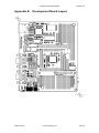
1
eCOG1k Development Kit
Version 1.2
Cyan Technology
eCOG1k Development Kit
User Manual
V1.2
29 March 2007
eCOG1X Development Kit
Version 1.0
Confidential and Proprietary Information
© Cyan Technology Ltd., 2005-2007
This document contains confidential and proprietary information of Cyan Technology Ltd. and is
protected by copyright laws. Its receipt or possession does not convey any rights to reproduce,
manufacture, use or sell anything based on information contained within this document.
Cyan TechnologyTM, the Cyan Technology logo and Max-eICETM are trademarks of Cyan
Holdings Ltd. CyanIDE® and eCOG® are registered trademarks of Cyan Holdings Ltd. Cyan
Technology Ltd. recognises other brand and product names as trademarks or registered
trademarks of their respective holders.
Any product described in this document is subject to continuous developments and
improvements. All particulars of the product and its use contained in this document are given by
Cyan Technology Ltd. in good faith. However, all warranties implied or expressed, including but
not limited to implied warranties of merchantability, or fitness for purpose, are excluded.
This document is intended only to assist the reader in the use of the product. Cyan Technology
Ltd. shall not be liable for any loss or damage arising from the use of any information in this
guide, any error or omission in such information, or any incorrect use of the product.
This product is not designed or intended to be used for on-line control of aircraft, aircraft
navigation or communications systems or in air traffic control applications or in the design,
construction, operation or maintenance of any nuclear facility, or for any medical use related to
either life support equipment or any other life-critical application. Cyan Technology Ltd.
specifically disclaims any express or implied warranty of fitness for any or all of such uses. Ask
your sales representative for details.
29 March 2007
Cyan Technology Ltd
Page i
eCOG1X Development Kit
Version 1.0
Revision History
Version
Date
Notes
V1.0
23/01/2006
First release.
V1.1
08/02/2006
Changes to examples for this hardware.
V1.2
29/03/2007
Updated for CyanIDE V1.4.
29 March 2007
Cyan Technology Ltd
Page ii
eCOG1X Development Kit
Version 1.0
Contents
List of Tables. . . . . . . . . . . . . . . . . . . . . . . . . . . . . . . . . . . . . . . . . . . . . . . . . v
1
Introduction . . . . . . . . . . . . . . . . . . . . . . . . . . . . . . . . . . . . . . . . . . . . 1
1.1
1.2
1.3
1.4
2
Development Kit Contents. . . . . . . . . . . . . . . . . . . . . . . . . . . . . . . . . . . . 1
Requirements . . . . . . . . . . . . . . . . . . . . . . . . . . . . . . . . . . . . . . . . . . . . . 1
Additional Documents . . . . . . . . . . . . . . . . . . . . . . . . . . . . . . . . . . . . . . . 1
Part Identification. . . . . . . . . . . . . . . . . . . . . . . . . . . . . . . . . . . . . . . . . . . 1
Quick Start . . . . . . . . . . . . . . . . . . . . . . . . . . . . . . . . . . . . . . . . . . . . . 2
2.1
2.2
2.3
3
Set Up System. . . . . . . . . . . . . . . . . . . . . . . . . . . . . . . . . . . . . . . . . . . . . 2
Copy the Example Projects . . . . . . . . . . . . . . . . . . . . . . . . . . . . . . . . . . . 2
Running an Example Project . . . . . . . . . . . . . . . . . . . . . . . . . . . . . . . . . . 2
Software . . . . . . . . . . . . . . . . . . . . . . . . . . . . . . . . . . . . . . . . . . . . . . . 3
3.1
3.2
4
CyanIDE . . . . . . . . . . . . . . . . . . . . . . . . . . . . . . . . . . . . . . . . . . . . . . . . . 3
USB eICE Drivers . . . . . . . . . . . . . . . . . . . . . . . . . . . . . . . . . . . . . . . . . . 3
Installing CyanIDE . . . . . . . . . . . . . . . . . . . . . . . . . . . . . . . . . . . . . . . 4
4.1
4.2
4.3
5
From the Cyan Tools CD-ROM . . . . . . . . . . . . . . . . . . . . . . . . . . . . . . . . 4
From the Cyan Website. . . . . . . . . . . . . . . . . . . . . . . . . . . . . . . . . . . . . . 4
Installing the USB eICE Driver . . . . . . . . . . . . . . . . . . . . . . . . . . . . . . . . 4
CyanIDE Examples . . . . . . . . . . . . . . . . . . . . . . . . . . . . . . . . . . . . . . 5
5.1
5.2
6
Development Board Examples . . . . . . . . . . . . . . . . . . . . . . . . . . . . . . . . 5
Simulator Examples. . . . . . . . . . . . . . . . . . . . . . . . . . . . . . . . . . . . . . . . 14
Development Board . . . . . . . . . . . . . . . . . . . . . . . . . . . . . . . . . . . . . 15
6.1
6.2
7
Overview . . . . . . . . . . . . . . . . . . . . . . . . . . . . . . . . . . . . . . . . . . . . . . . . 15
Description. . . . . . . . . . . . . . . . . . . . . . . . . . . . . . . . . . . . . . . . . . . . . . . 16
USB eICE Adaptor . . . . . . . . . . . . . . . . . . . . . . . . . . . . . . . . . . . . . . 17
7.1
7.2
29 March 2007
Overview . . . . . . . . . . . . . . . . . . . . . . . . . . . . . . . . . . . . . . . . . . . . . . . . 17
Description. . . . . . . . . . . . . . . . . . . . . . . . . . . . . . . . . . . . . . . . . . . . . . . 17
Cyan Technology Ltd
Page iii
eCOG1X Development Kit
8
Version 1.0
Connections and Jumper Links . . . . . . . . . . . . . . . . . . . . . . . . . . . . 18
8.1
8.2
8.3
8.4
8.5
8.6
8.7
8.8
8.9
8.10
8.11
8.12
8.13
8.14
8.15
8.16
8.17
8.18
8.19
J1: Power Supply. . . . . . . . . . . . . . . . . . . . . . . . . . . . . . . . . . . . . . . . . . 18
J2: eICE Debug Port . . . . . . . . . . . . . . . . . . . . . . . . . . . . . . . . . . . . . . . 18
J3: Expansion Port . . . . . . . . . . . . . . . . . . . . . . . . . . . . . . . . . . . . . . . . 19
J4: CS0 Enable . . . . . . . . . . . . . . . . . . . . . . . . . . . . . . . . . . . . . . . . . . . 19
J5: CPU Power . . . . . . . . . . . . . . . . . . . . . . . . . . . . . . . . . . . . . . . . . . . 19
J6: I2C Enable . . . . . . . . . . . . . . . . . . . . . . . . . . . . . . . . . . . . . . . . . . . . 20
J7: Buzzer Enable . . . . . . . . . . . . . . . . . . . . . . . . . . . . . . . . . . . . . . . . . 20
J8: LCD Enable . . . . . . . . . . . . . . . . . . . . . . . . . . . . . . . . . . . . . . . . . . . 20
J10-J13: CPU Pins . . . . . . . . . . . . . . . . . . . . . . . . . . . . . . . . . . . . . . . . 21
J14, J15: Serial Ports . . . . . . . . . . . . . . . . . . . . . . . . . . . . . . . . . . . . . . 22
J16: Serial Port Enable . . . . . . . . . . . . . . . . . . . . . . . . . . . . . . . . . . . . . 22
J17: SPI Enable. . . . . . . . . . . . . . . . . . . . . . . . . . . . . . . . . . . . . . . . . . . 22
J18: D.C. Power . . . . . . . . . . . . . . . . . . . . . . . . . . . . . . . . . . . . . . . . . . 23
J20: LED Enable . . . . . . . . . . . . . . . . . . . . . . . . . . . . . . . . . . . . . . . . . . 23
J21: CS1 Enable . . . . . . . . . . . . . . . . . . . . . . . . . . . . . . . . . . . . . . . . . . 23
J22, J30: Digital Inputs and Outputs . . . . . . . . . . . . . . . . . . . . . . . . . . . 24
J23-J26: Analogue Input Potentiometers . . . . . . . . . . . . . . . . . . . . . . . 25
J29: Radio Module Header . . . . . . . . . . . . . . . . . . . . . . . . . . . . . . . . . . 25
J31: Analogue Inputs and Outputs . . . . . . . . . . . . . . . . . . . . . . . . . . . . 25
Appendix A Important Notes . . . . . . . . . . . . . . . . . . . . . . . . . . . . . . . . . . . 26
Appendix B Development Board Layout . . . . . . . . . . . . . . . . . . . . . . . . . . 27
29 March 2007
Cyan Technology Ltd
Page iv
eCOG1X Development Kit
Version 1.0
List of Tables
1:
2:
3:
4:
5:
6:
7:
8:
9:
10:
11:
12:
13:
14:
15:
29 March 2007
J1: Power supply selection . . . . . . . . . . . . . . . . . . . . . . . . . . . . . . . . . . 18
J2: eICE header. . . . . . . . . . . . . . . . . . . . . . . . . . . . . . . . . . . . . . . . . . . 18
J3: Expansion port. . . . . . . . . . . . . . . . . . . . . . . . . . . . . . . . . . . . . . . . . 19
J6: I2C enable . . . . . . . . . . . . . . . . . . . . . . . . . . . . . . . . . . . . . . . . . . . . 20
J7: Buzzer enable . . . . . . . . . . . . . . . . . . . . . . . . . . . . . . . . . . . . . . . . . 20
J8: LCD enable . . . . . . . . . . . . . . . . . . . . . . . . . . . . . . . . . . . . . . . . . . . 20
J10-J13: CPU pins. . . . . . . . . . . . . . . . . . . . . . . . . . . . . . . . . . . . . . . . . 21
J14, J15: Serial ports. . . . . . . . . . . . . . . . . . . . . . . . . . . . . . . . . . . . . . . 22
J16: Serial port enable. . . . . . . . . . . . . . . . . . . . . . . . . . . . . . . . . . . . . . 22
J17: SPI enable . . . . . . . . . . . . . . . . . . . . . . . . . . . . . . . . . . . . . . . . . . . 22
J20: LED enable . . . . . . . . . . . . . . . . . . . . . . . . . . . . . . . . . . . . . . . . . . 23
J22: Ports K and L . . . . . . . . . . . . . . . . . . . . . . . . . . . . . . . . . . . . . . . . . 24
J30: Ports A and B. . . . . . . . . . . . . . . . . . . . . . . . . . . . . . . . . . . . . . . . . 24
J29: Radio module header . . . . . . . . . . . . . . . . . . . . . . . . . . . . . . . . . . 25
J31: Analogue inputs and outputs . . . . . . . . . . . . . . . . . . . . . . . . . . . . . 25
Cyan Technology Ltd
Page v
eCOG1X Development Kit
1
Introduction
1.1
Development Kit Contents
•
eCOG1k Development Board Issue 2.x
•
USB eICE adaptor
•
USB cable (A to mini-B)
•
10 way ribbon cable
•
Null modem serial cable
•
DC power supply
•
CD-ROM containing CyanIDE development software and documentation
1.2
Requirements
•
A Windows-based PC system.
(minimum 1GHz CPU speed, higher speed recommended).
•
Windows 2000 or Windows XP operating system.
•
100MB free disk space.
•
512MB memory (1GB recommended).
•
A spare USB port.
•
A spare serial port (optional).
•
System administrator privileges are required for software installation.
1.3
1.4
Version 1.0
Additional Documents
1.
eCOG1k User Manual
2.
CyanIDE User Manual
3.
eCOG1k Development Board V2 User Manual
4.
eCOG1 USB eICE Programming Adaptor User Manual
5.
TN006 Configuring the FTDI FT2232
Part Identification
In this document, any reference to eCOG1 means the generic chip and is applicable to all
versions. All eCOG1 devices are suffixed according to their version; any reference to a
particular version such as eCOG1k is specific to that version.
29 March 2007
Cyan Technology Ltd
Page 1
eCOG1X Development Kit
2
Version 1.0
Quick Start
Please also read Appendix A Important Notes.
2.1
Set Up System
•
Unpack and check contents of kit.
•
Install CyanIDE development software and USB device drivers.
See section 4 Installing CyanIDE for more details.
•
Check setting of jumper J1 on the Development Board is correct.
Link J1 pins 3-4 to power the board from the Cyan USB eICE adaptor.
See section J1: Power Supply for other options.
•
Connect the 9V d.c. power supply to the input jack J18.
•
Connect the 10-way ribbon cable between the USB eICE adaptor and connector J2 on
the Development Board.
•
Connect the USB cable between the eICE adaptor and the host PC.
•
Connect or turn on the mains input to the power supply.
2.2
Copy the Example Projects
CyanIDE includes a range of example projects for the development kits, copied during
installation into the <examples> directory under the CyanIDE install directory, usually
<C:\Program FIles\Cyan Technology\CyanIDE>. The installation process also creates a
<CyanIDE Projects> directory in the user’s My Documents folder. It is recommended that
the examples for the eCOG1k development kit are copied into this projects directory before
use, to avoid making any changes to the original examples.
•
Open the My Documents directory and browse into the CyanIDE Projects directory. This
includes a shortcut to the CyanIDE examples directory.
•
Open the <CyanIDE Examples> shortcut and then the examples directory for this
development board <eCOG1k dev board v2\general>.
•
Type ctrl-A or click Edit->Select All to select all the eCOG1k example projects, then
type ctrl-C or click Edit->Copy to copy them to the clipboard.
•
Click the Back button three times to return to the CyanIDE Projects directory.
•
Type ctrl-V or click Edit->Paste to paste the example projects from the clipboard into
the current directory.
2.3
Running an Example Project
As an introduction, try the LED example project located in the <led> directory.
•
Start CyanIDE.
•
From the main menu, select Project->Open and browse to the LED example directory
<CyanIDE Projects\led>. Select the project file <*.cyp> and click Open. CyanIDE loads
the project and displays the files included in the project in the navigator pane at the left
of the main window.
•
Select Build->Rebuild All from the main menu. This compiles the project source files
and links the object code into a download image file.
•
Select Debug->Run. CyanIDE connects to the eCOG1k target processor on the
development board, downloads the application code and begins execution.
29 March 2007
Cyan Technology Ltd
Page 2
eCOG1X Development Kit
3
3.1
Version 1.0
Software
CyanIDE
The CyanIDE software development package supports the eCOG1 family of
microcontrollers, providing project management, source code editor, C compiler, assembler,
linker, source level debugger, and online help files. It is available on CD-ROM, or as a
download to registered users on the Cyan web site at www.cyantechnology.com.
CyanIDE communicates with the eCOG1k microcontroller on the target system via the eICE
debug port. The host PC requires a simple eICE adaptor that connects to the 10-way header
J2 on the development board. The development kit includes the Cyan USB eICE adaptor.
CyanIDE includes a range of example applications for the development board. These can
provide a good starting point for customer applications, or just as examples showing how to
set up a software project. Further application examples including CyanIDE project files with
source code are available on the web site support pages.
3.2
USB eICE Drivers
The software drivers for the USB eICE adaptor are included in the CyanIDE development
package. CyanIDE V1.4 or later includes the required version of the driver files as standard.
To ensure that the driver files are present, install the CyanIDE software and any necessary
updates before connecting the eICE adaptor to the host PC. Further details about the
software installation are shown later in this document.
Note that any previous version of CyanIDE should be uninstalled before the latest version is
installed. This includes any USB device drivers for Cyan products such as the evaluation
board, which should be removed via the Device Manager. Installing the new version of
CyanIDE also reinstalls the USB eICE device driver.
29 March 2007
Cyan Technology Ltd
Page 3
eCOG1X Development Kit
4
Version 1.0
Installing CyanIDE
4.1
From the Cyan Tools CD-ROM
Insert the CD into the CD-ROM drive. The html start page should load automatically in the
default browser.
If the start page does not load automatically, or Autorun is disabled for the CD-ROM drive,
then Browse the Cyan CD in a file manager or explorer window, and open the file
<index.htm>.
When the start page is displayed, click on the Menu button, then select the Install CyanIDE
item to begin installation of the development software. Follow the instructions presented by
the installation program.
4.2
4.3
From the Cyan Website
•
Navigate to the software downloads page on the website, located at http://
www.cyantechnology.com/support/updates.php.
•
Download the CyanIDE full version installation file to a temporary directory.
Please note that users must log in to the website with their registered account name
and password for the support forum to download this file.
•
Execute the downloaded file to install the development software. Follow the instructions
presented by the installation program.
Installing the USB eICE Driver
CyanIDE V1.4 includes the driver for the USB eICE adaptor as standard, and it is not
necessary to install them separately.
When an eICE adaptor is connected to a PC for the first time, the USB enumeration process
identifies it as new hardware, and Windows starts the Found New Hardware process. Driver
installation under Windows 2000 and Windows XP is fully automatic and does not require
any user interaction.
29 March 2007
Cyan Technology Ltd
Page 4
eCOG1X Development Kit
5
Version 1.0
CyanIDE Examples
CyanIDE includes a number of example software projects, pre-configured for use with the
eCOG1k development board, the eCOG1k evaluation board or the eCOG1 simulator. The
examples for the eCOG1k development board are described briefly here.
5.1
Development Board Examples
The following example applications for this version of the development board are included
as standard with CyanIDE V1.4.
Example
Comments
adc_test
Using the analogue-to-digital converter
cache
Demonstrates various cache modes
clock
Implements a time-of-day clock using low-power sleep mode
dev_pcb
The software shipped on the development board
dhry
The Dhrystone benchmark
duart_irq
DUART serial port using interrupts and circular buffers
ForthCLI
A simple FORTH Command Line Interpreter
i2c_nvm
Uses the DUSART I2C function to test an external EEPROM
irom1k
A memory-resident application to program the internal flash memory
led
Uses a timer to flash LEDs on the development board
perfect
Searches for perfect numbers
sdram
Performs a memory test on the external SDRAM
spi_dac
Uses the DUSART SPI function for an external serial DAC
uip-cyan\ecog1\* uIP TCP/IP stack and sample applications
Many examples use one of the serial ports to report results or display messages. Use a
terminal program such as 'HyperTerminal' to communicate with the application. The default
serial port configuration is shown below.
•
9600 Baud
•
8 data bits
•
no parity bits
•
one stop bit
•
no flow control
29 March 2007
Cyan Technology Ltd
Page 5
eCOG1X Development Kit
5.1.1
Version 1.0
adc_test
The 'adc_test' application demonstrates reading analogue input values via the ADC. The
example uses counter CNT1 as a timer to trigger readings at a preset interval and averages
the results over a number of readings. It uses DUART channel A to implement an interruptdriven serial port for both standard input and output. Entering one of the characters 'A', 'R',
'S', 'T' or 'V' changes the selection and configuration of the ADC input channels. The values
are output via the serial port.
In order to use the stdio.h functions such as printf() and scanf(), users must supply
versions of putchar() and _getchar(). These functions are contained in the main
application file.
File
Comments
adc.cyp
CyanIDE project file
cstartup.asm
C environment initialisation
irq.asm
Entry point and interrupt vectors
adc.c
Application code
devboard.cfg
Peripheral configuration file
internal.map
Memory map
5.1.2
cache
The 'cache' application runs a quick benchmark program with different cache configurations
and displays achieved performance values based on the execution time for each
configuration. The performance figures are reported via DUART channel A. The TMR timer
is used to measure the execution times of the benchmark routines. This code demonstrates
the following features:
•
Use of the cache
•
Interrupts in C
•
Clock configuration in the SSM (System Support Module)
•
Use of the TMR timer
•
Use of the DUART serial port
File
Comments
cache.cyp
CyanIDE project file
cstartup.asm
C environment initialisation
irq.asm
Entry point and interrupt vectors
cache.c
Application code
devboard.cfg
Peripheral configuration file
internal.map
Memory map
29 March 2007
Cyan Technology Ltd
Page 6
eCOG1X Development Kit
5.1.3
Version 1.0
clock
The 'clock' application outputs a time value (hh:mm:ss) every second. The time is displayed
on the LCD and echoed via DUART channel A. Counter CNT1 is used as a timer to generate
an interrupt at 1 second intervals. On each interrupt, the processor is woken from the sleep
state and set to stay awake. The main routine outputs the time and puts the CPU back to
sleep. This code demonstrates the following features.
•
Interrupts in C
•
Sleep mode
•
Deactivating clocks for sleep mode
•
Waking up using peripheral interrupts
•
Clock configuration in the SSM
•
Use of counter CNT1 as a timer
•
Use of the DUART serial port
For further information on low power operation refer to Application Notes AN004 and AN008
on the Cyan CD-ROM.
File
Comments
clock.cyp
CyanIDE project file
cstartup.asm
C environment initialisation
irq.asm
Entry point and interrupt vectors
clock.c
Application code
putchar.c
Character output routine
devboard.cfg
Peripheral configuration file
internal.map
Memory map
29 March 2007
Cyan Technology Ltd
Page 7
eCOG1X Development Kit
5.1.4
Version 1.0
dev_pcb
The 'dev_pcb' application is shipped with the development board. The software
demonstrates the following:
•
The DUART serial port
•
GPIO for inputs and outputs
•
LCD driven from GPIO
•
Reading analogue inputs via the ADC
•
The SDRAM Controller
•
Using counter CNT1 as a timer
•
Interrupts in C
One of four tests is selected by setting DIP switches 1 and 2. Results are displayed on the
LCD and via DUART channel A.
File
Comments
dev_pcb.cyp
CyanIDE project file
cstartup.asm C environment initialisation
irq.asm
Entry point and interrupt vectors
adc.c/h
ADC code
ethernet.c/h
Ethernet code
isr.c
Interrupt handlers
main.c
C entry point code
util.c/h
Utility routines
welcome.c/h
Welcome message code
devboard.cfg Peripheral configuration file
internal.map
5.1.5
Memory map
dhry
The 'dhry' application demonstrates the eCOG1k running the Dhrystone benchmarks. The
application's stdin and stdout paths are supported via DUART channel A. The Dhrystone
benchmark code measures its own performance and reports the results through stdout. The
TMR timer is used to measure the execution time of the benchmark program. Both
benchmarks require the following three support functions to be implemented:
•
int putchar(int c)
•
int _getchar(void)
•
double dtime(void)
File
Comments
dhry11.cyp
CyanIDE project file for Dhrystone 1.1
dhry21.cyp
CyanIDE project file for Dhrystone 2.1
cstartup.asm C environment initialisation
irq.asm
Entry point and interrupt vectors
crt.c
C runtime initialisation
crt_asm.asm C runtime initialisation assembly code
dhry11.c
Dhrystone 1.1 source code
dhry.h
Dhrystone 2.1 header
dhry21a.c
Dhrystone 2.1 source code
dhry21b.c
Dhrystone 2.1 source code
internal.map
Memory map
29 March 2007
Cyan Technology Ltd
Page 8
eCOG1X Development Kit
5.1.6
Version 1.0
duart_irq
The 'duart_irq' application demonstrates how to use the DUART for an interrupt-driven serial
port with circular buffers. Standard input and output is through DUART channel A. All
characters that the application receives are echoed back. In order to use the stdio.h
functions such as printf() and scanf(), users must supply versions of putchar() and
_getchar(). These functions are contained in the main application file.
File
Comments
duart.cyp
CyanIDE project file
cstartup.asm
C environment initialisation
irq.asm
Entry point and interrupt vectors
duart.c
Application code
devboard.cfg
Peripheral configuration file
internal.map
Memory map
5.1.7
ForthCLI
The 'ForthCLI' application implements a simple command line interpreter, using the Forth
language. It is described in more detail in Application Note AN020.
File
Comments
ForthCLI.cyp
CyanIDE project file
cstartup.asm
C environment initialisation
irq.asm
Entry point and interrupt vectors
main.c
Application code
devBoard.c/h
Board-specific functions
Kernel.c/h
Forth CLI kernel
Memory.c/h
Variables and definitions for the Forth memory, stacks, dictionary, etc.
RS232.c/h
Interrupt-driven serial port using DUART A.
StdDefs.h
Common definitions
ecog1.cfg
Peripheral configuration file
internal.map
Memory map
5.1.8
i2c_nvm
The 'i2c_nvm' application configures the DUSART as an I2C port and performs a read/write
test on an external 24LC32A serial EEPROM device. The application reports test results
through DUART channel A.
This example is described in more detail in Application Note AN029.
File
Comments
i2c_nvm.cyp
CyanIDE project file
cstartup.asm
C environment initialisation
irq.asm
Entry point and interrupt vectors
i2c_nvm.c
Application code – memory test
i2c.c
Interrupt-driven I2C read and write routines
putchar.c
Character output routine for printf
serial.c/h
Interrupt driven buffered serial port on DUART channel A
timer.c/h
1ms tick timer
devboard.cfg
Peripheral configuration file
internal.map
Memory map
29 March 2007
Cyan Technology Ltd
Page 9
eCOG1X Development Kit
5.1.9
Version 1.0
irom1k
The 'irom1k' application demonstrates how to program the internal flash memory of the
eCOG1k. The program runs in internal RAM and so the MMU must be set after the program
has been downloaded to map the IRAM internal ram area as CODE space. This is
performed using a Python initialisation function that is installed when then project is loaded.
A program similar to this one is used by CyanIDE to program the eCOG1k when a
<project>.rom file is downloaded.
For further information on programming the internal flash memory, refer to Application Notes
AN001, AN018 and AN019 on the Cyan CD-ROM. For information and examples on
programming external flash memory, refer to Application Note AN002.
File
Comments
irom1k.cyp
CyanIDE project file
cstartup.asm
C environment initialisation
irq.asm
Entry point and interrupt vectors
flash.c
Main application code
fmc.c/h
Flash programming code
tim.c/h
Timing functions
initfunc.py
Python script code to set up the MMU.
The Run on project load option for this file is set.
iram.map
Memory map
5.1.10
led
The 'led' application uses counter CNT1 as a timer to control the flashing of four LEDs
connected to GPIO output signals.
File
Comments
led.cyp
CyanIDE project file
cstartup.asm
C environment initialisation
irq.asm
Entry point and interrupt vectors
led.c
Application code
devboard.cfg
Peripheral configuration file
internal.map
Memory map
5.1.11
perfect
The 'perfect' application searches for perfect numbers and outputs them via DUART channel
A. A perfect number is one whose divisors sum to itself.
File
Comments
perfect.cyp
CyanIDE project file
cstartup.asm
C environment initialisation
irq.asm
Entry point and interrupt vectors
perfect.c
Application code
putchar.c
Character output routine
devboard.cfg
Peripheral configuration file
internal.map
Memory map
29 March 2007
Cyan Technology Ltd
Page 10
eCOG1X Development Kit
5.1.12
Version 1.0
sdram
The 'sdram' application configures the EMI (external memory interface) peripheral for an
SDRAM and performs a test to verify that the memory interface is working. The SDRAM
must be compatible with a Samsung S281632B. The application outputs test results through
DUART channel A.
For further information on using the eCOG1k with an external SDRAM refer to Application
Note AN003 on the Cyan CD-ROM.
File
Comments
sdram.cyp
CyanIDE project file
cstartup.asm
C environment initialisation
irq.asm
Entry point and interrupt vectors
sdram.c
Application code
Putchar.c
Character output routine
devboard.cfg
Peripheral configuration file
internal.map
Memory map
5.1.13
spi_dac
The 'spi_dac' application uses the DUSART SPI function to control an external serial
two-channel 12-bit digital-to-analogue converter, a Linear Technology LT1446L. The
application reports test results through DUART channel A.
This example is described in more detail in Application Note AN031.
File
Comments
spi_dac.cyp
CyanIDE project file
cstartup.asm
C environment initialisation
irq.asm
Entry point and interrupt vectors
spi_dac.c
Application code
putchar.c
Character output routine
devboard.cfg
Peripheral configuration file
internal.map
Memory map
29 March 2007
Cyan Technology Ltd
Page 11
eCOG1X Development Kit
5.1.14
Version 1.0
uIP TCP/IP stack
uIP is a very small implementation of the TCP/IP stack, written by Adam Dunkels
([email protected]). More information can be found on the uIP homepage at http://
www.dunkels.com/adam/uip. This port to the eCOG1k microcontroller development board
was done by Javier Cardona of CozyBit.
The uIP stack and the httpd server example code have been modified by Cyan to improve
performance and reduce code size on the eCOG1k. These changes are specific to the
eCOG1k processor and are not part of the standard uIP distribution.
The directory structure is as follows:
uip-cyan\apps\
Example applications
uip-cyan\doc\
uIP Documentation
uip-cyan\uip\
The uIP TCP/IP, SLIP and ARP code
uip-cyan\ecog1\*
uIP applications for the eCOG1k development board
There is more information in the on-line help pages. The Cyan software CD-ROM includes
both a tutorial for this example and the complete uIP documentation. Application Note
AN017 provides an introduction to the uIP TCP/IP stack and describes the embedded web
server implementation in more detail.
The 'httpd' application demonstrates an embedded web page server.
File
Comments
ecog1\httpd\httpd.cyp
CyanIDE project file
ecog1\httpd\cstartup.asm
C environment initialisation
ecog1\httpd\irq.asm
Entry point and interrupt vectors
ecog1\httpd\main.c
Application code
ecog1\httpd\putchar.c
Character output routine
ecog1\httpd\apphdr.h
Application-specific header file
(names the application called by uIP)
ecog1\httpd\utils.asm
Byte swap (16-bit) and byte reverse (32-bit) routines in
assembler for speed (not used)
ecog1\httpd\devboard.cfg
Peripheral configuration file
ecog1\httpd\internal.map
Memory map
The 'telnetd' application provides a telnet server and a very simple command line interpreter.
File
Comments
ecog1\telnetd\telnetd.cyp
CyanIDE project file
ecog1\telnetd\cstartup.asm
C environment initialisation
ecog1\telnetd\irq.asm
Entry point and interrupt vectors
ecog1\telnetd\main.c
Application code
ecog1\telnetd\putchar.c
Character output routine
ecog1\telnetd\apphdr.h
Application-specific header file
(names the application called by uIP)
ecog1\telnetd\devboard.cfg
Peripheral configuration file
ecog1\telnetd\internal.map
Memory map
29 March 2007
Cyan Technology Ltd
Page 12
eCOG1X Development Kit
Version 1.0
The 'dumper' utility puts the Ethernet device into promiscuous mode and echoes the
contents of all received packets to the serial port.
File
Comments
ecog1\dumper\dumper.cyp
CyanIDE project file
ecog1\dumper\cstartup.asm
C environment initialisation
ecog1\dumper\irq.asm
Entry point and interrupt vectors
ecog1\dumper\main.c
Application code
ecog1\dumper\putchar.c
Character output routine
ecog1\dumper\apphdr.h
Application-specific header file
(names the application called by uIP)
ecog1\dumper\devboard.cfg
Peripheral configuration file
ecog1\dumper\internal.map
Memory map
Common files
File
Comments
ecog1\irqutil.c
Utility functions called from interrupt service routines
ecog1\slipdev.c
Low level UART functions for the SLIP protocol
ecog1\smsc91c111.*
ecog1\smsc91c111_defs.h
The SMSC91C111 device driver
ecog1\timeofday.*
Basic time functions
ecog1\uiparch.c
Architecture-dependent uIP functions
ecog1\uipopt.h
Configuration options for uIP
uIP files
File
Comments
apps\httpd\cgi.*
HTTP server cgi script language functions
apps\httpd\fs.*
HTTP server read-only file system code
apps\httpd\fsdata.*
Constant data for HTTP server read-only file system
apps\httpd\httpd.*
httpd embedded Web server
apps\resolv\resolv.*
Hostname resolver functions
apps\smtp\smtp.*
SMTP E-mail sender functions
apps\smtp\smtp_strings.*
Constant strings for SMTP E-mail sender
apps\telnet\telnet.*
Telnet client
apps\telnetd\memb.*
Memory block allocation routines
apps\telnetd\telnetd.*
Telnet server
apps\telnetd\telnetd_shell.*
Telnet server shell
apps\webclient\webclient.*
HTTP web client
apps\webclient\http_strings.*
Constant strings for HTTP web client
29 March 2007
Cyan Technology Ltd
Page 13
eCOG1X Development Kit
5.2
Version 1.0
Simulator Examples
The following example simulator applications are also included with CyanIDE. They can be
found in the <examples\simulator> directory located below the CyanIDE installation
directory.
Example
Comments
primes
Searches for prime numbers
oscillator
Example of using a simulated memory-mapped device
5.2.1
primes
The 'primes' application searches for prime numbers and displays results in the Debug
Output Window. The results are displayed using an implementation of putchar() that
includes the assembler PRINT instruction. The simulator interprets this instruction according
to the Print mode option in Project Properties: printing a character, a hexadecimal value,
or raising an exception.
File
Comments
primes.cyp
CyanIDE project file
cstartup.asm
C environment initialisation
irq.asm
Entry point and interrupt vectors
primes.c
Application code
putchar.c
Character output routine
simulator.map
Memory map
5.2.2
oscillator
The 'oscillator' application reads a simulated ADC, which is generating data representing a
sine wave, and writes a filtered value back to a memory location. The filtered value is logged
to a file.
File
Comments
oscillator.cyp
CyanIDE project file
cstartup.asm
C environment initialisation
irq.asm
Entry point and interrupt vectors
oscillator.c
Application code
putchar.c
Character output routine
oscillator.py
Simulated ADC written in Python.
The Run on project load option for this file is set.
simulator.map
Memory map - includes CUSTOM entry
29 March 2007
Cyan Technology Ltd
Page 14
eCOG1X Development Kit
6
Version 1.0
Development Board
6.1
Overview
The Development Board has the following major features.
•
eCOG1k microcontroller with 32Kwords internal flash memory.
•
512K x 16 bit external flash memory.
•
8M x 16 bit SDRAM.
•
10/100 Mbits/s Ethernet interface using the SMSC LAN91C111 device.
•
16 character x 2 row LCD.
•
10 way boxed header for eICE debug port.
•
Two RS-232 serial ports.
•
I2C serial EEPROM (24LC32A).
•
Four 12-bit analogue inputs.
•
Two 12-bit analogue outputs via SPI DAC (LTC1446L).
•
Four user/status LEDs.
•
Four user switches.
•
Piezo sounder.
•
Breadboard prototyping area.
•
Various pin headers for input and output ports.
•
Powered from an eICE adaptor or from a d.c. input jack.
29 March 2007
Cyan Technology Ltd
Page 15
eCOG1X Development Kit
6.2
Version 1.0
Description
The eCOG1k microcontroller has a 16-bit CPU architecture and a wide range of on-chip
peripherals. It operates at clock speeds of up to 25MHz internally from a 5MHz crystal or
32.768kHz watch crystal. Refer to the eCOG1k User Manual for further details.
A Spansion (AMD/Fujitsu) S29AL008 device provides 512Kwords of external flash memory.
This is connected to the external memory interface (EMI) in standard bus mode and is
enabled by chip select CS1 for physical addresses below 0x80000 (A19 = 0).
A Samsung K4S281632 SDRAM provides 8Mwords of external memory. It is connected to
the EMI peripheral in SDRAM mode, with no glue logic required, and is enabled by chip
select CS0.
The Ethernet interface uses the SMSC LAN91C111 device which is suitable for non-PC bus
architectures. It is connected as a memory-mapped peripheral with a 16-bit data bus. It is
enabled by chip select CS1 for physical addresses above 0x8000 (A19 = 1). The board has
a 10/100baseT transceiver and an RJ45 socket fitted.
The board is fitted with a 10-way boxed header for the eICE debug port. This port connects
directly to the processor core, and is used for downloading and debugging applications
code. A Cyan USB eICE adaptor is supplied with the Development Board, although any
external eICE adaptor may be used.
Two serial ports are available on the Development Board. J14 is fitted with a 9-way D-type
plug and is wired as a DTE port, while J15 is fitted with a 9-way socket and is wired as a
DCE port. A null-modem serial cable is provided to connect a PC serial port to J14. To
connect a PC serial port to J15, use a standard straight-through serial cable (not supplied).
A 24LC32A I2C serial EEPROM provides a small amount of additional non-volatile storage
for use in applications. It is connected to port C, which may be configured as one of the two
DUSART serial channels. The I2C protocol is supported by the DUSART peripheral.
The four 12-bit analogue inputs on the eCOG1k device are available on pin header J31. The
analogue inputs can be connected individually to onboard potentiometers VR1-VR4 for
testing, or to 0V, by fitting jumper links to pin headers J23-J26. Two analogue outputs are
also available on J31, driven from an LTC1446L two-channel 12-bit DAC with an SPI
connection. This device is connected to pins on port A, which may be configured for one or
both of the DUSART serial channels.
The Development Board can be powered from an external d.c. power supply, connected via
a standard input jack, or from the eICE debug connection. Jumper J1 selects the power
supply source.
Note that when an eICE adaptor is used to power the board, the LCD backlight is not
powered. In addition, it is unlikely that a USB eICE adaptor can provide enough supply
current to power the Ethernet interface. The maximum supply current available to a USB
bus-powered slave device is only 500mA at 5V. If either the LCD backlight or the Ethernet
interface is required, then it is recommended that the board is powered from an external d.c.
power supply, nominally 9V, via the input jack.
The four LEDs are connected to the eCOG1k on port K_0 to K_3. DIP switch SW2 is
connected on port K_4 to K_7. Leave the switches in the off position to allow the use of port
K elsewhere if required.
The LCD is controlled by signals on port L. The high four bits of the LCD data bus are
connected via buffer U9 to port L_0 to L_3. Port L_4 is connected to the LCD register select
input RS, port L_5 to the read/write direction input R/W, and port L_6 to the enable input E.
The board support library includes routines for driving the LCD with GPIO lines assigned to
these port pins.
29 March 2007
Cyan Technology Ltd
Page 16
eCOG1X Development Kit
7
Version 1.0
USB eICE Adaptor
7.1
Overview
The USB eICE adaptor has the following major features.
7.2
•
FTDI FT2232 device providing USB interface.
•
USB mini-B socket.
•
USB cable (A to mini-B) for host PC connection.
•
10 way boxed header and ribbon cable for eICE debug port.
•
Powered from USB +5V supply.
Description
The USB eICE adaptor uses the FTDI FT2232 device to implement the USB interface. It has
a standard USB cable permanently attached to the host side of the unit, with a type A USB
connector fitted. The eICE connection to the eCOG1k target device is via a 10 way boxed
header and ribbon cable. The FT2232 device provides the USB interface to the host PC and
digital inputs and outputs for the eICE signals.
A 93C56 serial EEPROM provides non-volatile storage for the FT2232 configuration data
including serial numbers, USB PID and VID numbers, and identifier strings. This
configuration data is required to allow the unit to identify itself to the host PC during the USB
device enumeration process, and for the PC then to select the correct device driver files.
The Cyan USB eICE adaptors are loaded with the required configuration data during
functional test.
The adaptor is powered from the +5V supply available on the host USB connection. The
FT2232 device includes an on-chip regulator which provides 3.3V for the I/O connections to
the eCOG1k target device. An external transistor connects to the bidirectional signal
eICE_LOADB, used for handshaking eICE messages.
All signals to the eICE connection include 100Ω series resistors. The LOADB signal also
includes a 4.7kΩ pull-up resistor. The USB +5V supply is also connected to the 10 way
header; this may be used to power small target systems provided the total current drawn is
within the 500mA limit available from a standard USB host.
29 March 2007
Cyan Technology Ltd
Page 17
eCOG1X Development Kit
8
8.1
Version 1.0
Connections and Jumper Links
J1: Power Supply
The development board can be powered from an external d.c. supply via an input jack, or
from the eICE adaptor. Header J1 selects which power supply source is used to power the
board.
The external power supply from the input jack J14, nominally 9V, is regulated down to 5V.
This is VCCIN5 on J1 pin 1, and is used directly to power the LCD backlight. To power the
board from the regulated external supply, link J1 pins 1-3. This connects the regulated input
5V supply to a second 3.3V regulator which powers the rest of the board. The input to this
3.3V regulator is VCC5 on J1 pin 3.
The power connection from the eICE adaptor is labelled VDD_EICE on J1 pin 4. This can be
used to power the board from the supply provided by the eICE adaptor, instead of from an
external supply. Check the voltage of the power supply output on the eICE adaptor. If it is
5V, then link J1 pins 3-4 to connect this 5V supply to the input of the 3.3V regulator. If it is
3.3V, then link J1 pins 2-4 to bypass the 3.3V regulator and connect directly to the
development board 3.3V power supply rail.
J1
V CCIN5
1
2
V DD
V CC5
3
4
V DD_EICE
Table 1: J1: Power supply selection
The Cyan USB eICE adaptor provides 5V d.c. on the VDD_EICE pin, from the USB hub on
the host PC. To use this to power the board, connect J1 pins 3-4.
Note that the LCD backlight is powered only when the board is powered from the external
supply, not the eICE adaptor. It is also likely that an external supply will be necessary when
using the Ethernet interface, as this requires more supply current than is available from a
normal USB connection.
Important note: Do not connect J1 pins 1-2. This connects the 5V supply input (regulated
from the external 9V supply) directly to the 3.3V power plane. Connecting J1 pins 1-2 with
external power applied is likely to damage at least some components on the development
board.
8.2
J2: eICE Debug Port
The pin connections for the eICE signals on the 10 way boxed header J2 are shown in the
table below.
J2
eICE_MOSI
1
2
V DD_EICE
eICE_CS
3
4
GND
eICE_LOA DB
5
6
GND
eICE_CLOCK
7
8
eICE_MISO
9
10
GND
Res erv ed
(do not c onnec t)
Table 2: J2: eICE header
The Cyan USB eICE adaptor provides 5V d.c. on the VDD_EICE pin, from the USB hub on
the host PC. To use this to power the board, connect J1 pins 3-4.
29 March 2007
Cyan Technology Ltd
Page 18
eCOG1X Development Kit
8.3
Version 1.0
J3: Expansion Port
This header provides access to the CPU address bus, data bus and control lines for user
expansion or debugging.
J3
A0
1
2
A1
A2
3
4
A3
A4
5
6
A5
A6
7
8
A7
V CC3.3
9
10
V CC3.3
A8
11 12
A9
A 10
13 14
A 11
A 12
15 16
A 13
A 14/DQM0
17 18
A 15/DQM1
GND
19 20
GND
D0
21 22
D1
D2
23 24
D3
D4
25 26
D5
D6
27 28
D7
GND
29 30
GND
D8
31 32
D9
D10
33 34
D11
D12
35 36
D13
D14
37 38
D15
GND
39 40
GND
nCS0
41 42
nCS1
DS1/RA S
43 44
DS0/CA S
nWE
45 46
CKE
WA IT
V CC5
47 48
49 50
CLOCK
V CC5
Table 3: J3: Expansion port
8.4
J4: CS0 Enable
Header J4 connects the chip select output CS0 to the external SDRAM device. Fit a link to
J4 to enable the SDRAM, or remove the link to disable it.
8.5
J5: CPU Power
The 3.3V power supply for the eCOG1k microcontroller is connected through header J5. A
link must be fitted to J5 for normal operation.
This allows the supply current drawn by the eCOG1k to be measured. Remove the link, and
connect an ammeter between J5 pins 1 and 2. The ammeter measures the supply current to
the eCOG1k. Note that in standby or low power operating modes, the supply current is
comparable with the input and output leakage currents. This makes it difficult to measure the
supply current accurately in low power modes when the eCOG1k is connected to other
active devices.
29 March 2007
Cyan Technology Ltd
Page 19
eCOG1X Development Kit
8.6
Version 1.0
J6: I2C Enable
Header J6 connects the 24LC32A I2C EEPROM device U8 to the eCOG1k on port C_0 and
C_1. To enable this device, link J6 pins 1-2 and 3-4. To disable this device and leave these
port pins available for use elsewhere, remove the two links.
J6
PORTC_0
1
2
I2C_SCL
PORTC_1
3
4
I2C_SDA
Table 4: J6: I2C enable
8.7
J7: Buzzer Enable
Header J7 connects the piezo buzzer to the eCOG1k PWM1 output on port J_6. Port J_7 is
also available but is not currently used. To enable the piezo buzzer for use with PWM1 on
port J_6, link J7 pins 1-2. To enable the piezo buzzer with PWM2 on port J_7, connect J7
pins 2-3 with a wire link. To disable the buzzer and leave the port pins available for use
elsewhere, remove any links.
J7
PORTJ_6
1
2
PORTJ_7
3
4
BUZ Z ER
Table 5: J7: Buzzer enable
8.8
J8: LCD Enable
Header J8 allows the LCD to be enabled or disabled. It connects the LCD enable input to
eCOG1k port L_6, and controls the enable input for the buffer U9 which links the LCD data
bus signals D4-D7 to the eCOG1k on port L_0 to L_3. To enable the LCD, link J8 pins 1-2
and 3-4. To disable the LCD and buffer and leave port L available for use elsewhere,
remove the two links.
J8
PORTL_6
1
2
LCD_E
GND
3
4
/U9_OE
Table 6: J8: LCD enable
29 March 2007
Cyan Technology Ltd
Page 20
eCOG1X Development Kit
8.9
Version 1.0
J10-J13: CPU Pins
All the CPU pins are accessible on these connectors.
J10
PortE 7
PortE 5
PortE 3
PortE 1
GND
V CC3.3
PortK 7
NC
GND
PortK 5
V CC3.3
eICE MISO
eICE Cloc k
eICE CS
GND
GND
J11
1
3
5
7
9
11
13
15
17
19
21
23
25
27
29
31
2
4
6
8
10
12
14
16
18
20
22
24
26
28
30
32
PortE 6
PortE 4
PortE 2
PortE 0
CPU break
GND
PortK 6
V CC3.3
NC
PortK 4
GND
eICE MOSI
eICE LOA DB
GND
GND
A GND
V CC3.3
V in2
V in4
Res et In
PortA 1
PortA 3
PortA 5
PortA 7
GND
PortB 1
PortB 3
PortB 5
PortB 7
PortC 1
PortC 3
GND
J12
PortD 2
Por tL 0
Por tL 2
Por tL 4
Por tL 6
V c c 3.3
PortK 0
NC
V CC3.3
PortK 2
PortJ 0
PortJ 2
PortJ 4
PortJ 6
Por tI 7
Por tI 5
1
3
5
7
9
11
13
15
17
19
21
23
25
27
29
31
2
4
6
8
10
12
14
16
18
20
22
24
26
28
30
32
V in1
V in3
Res et Out
PortA 0
PortA 2
PortA 4
PortA 6
V CC3.3
PortB 0
PortB 2
PortB 4
PortB 6
PortC 0
PortC 2
PortD 0
PortD 1
1
3
5
7
9
11
13
15
17
19
21
23
25
27
29
31
2
4
6
8
10
12
14
16
18
20
22
24
26
28
30
32
PortI 2
PortI 0
GND
PortH 6
PortH 4
PortH 2
PortH 0
PortG 6
PortG 4
PortG 2
PortG 0
GND
PortF 6
PortF 4
PortF 2
PortF 0
J13
1
3
5
7
9
11
13
15
17
19
21
23
25
27
29
31
2
4
6
8
10
12
14
16
18
20
22
24
26
28
30
32
Por tD 3
Por tL 1
Por tL 3
Por tL 5
Por tL 7
GND
Por tK 1
GND
NC
Por tK 3
Por tJ 1
Por tJ 3
Por tJ 5
Por tJ 7
Por tI 6
Por tI 4
PortI 3
PortI 1
V CC3.3
PortH 7
PortH 5
PortH 3
PortH 1
PortG 7
PortG 5
PortG 3
PortG 1
V CC3.3
PortF 7
PortF 5
PortF 3
PortF 1
Table 7: J10-J13: CPU pins
29 March 2007
Cyan Technology Ltd
Page 21
eCOG1X Development Kit
8.10
Version 1.0
J14, J15: Serial Ports
J14 and J15 are standard PC compatible 9-way D-type serial connectors. J14 is a plug,
wired as a DTE, and requires a null-modem cable to connect to a PC. J15 is a socket, wired
as a DCE, and requires a standard straight-through cable to connect to a PC. It also
provides support for RTS/CTS hardware handshake signals using two GPIO lines.
J14
J15
GND 5
NC 1
6 NC
6 NC
NC 4
TX 2
7 NC
7 CTS
TX 3
RX 3
8 NC
8 RTS
RX 2
NC 4
9 NC
9 NC
NC 1
GND 5
Table 8: J14, J15: Serial ports
8.11
J16: Serial Port Enable
Header J16 connects the serial port RS-232 transceiver device to eCOG1k ports D and J.
To connect the transceiver to the port pins, link across all pins on J16 (1-2, 3-4, etc.). To
disconnect the RS-232 transceiver and leave these port pins available for use elsewhere,
remove the links.
J16
PORTJ_1
1
2
TXA
PORTD_1
3
4
TXB
PORTD_3
5
6
RTSB
PORTJ_0
7
8
RXA
PORTD_0
9
10
RXB
PORTD_2
11
12
CTSB
Table 9: J16: Serial port enable
8.12
J17: SPI Enable
Header J17 connects the LTC1446L SPI DAC device U15 to the eCOG1k SPI chip select
output on port A_3. It also connects a second SPI chip select output on port A_4 to header
J29 pin 9 for use with other external devices. To enable these SPI devices, link J17 pins 1-2
and 3-4. To disable these devices and leave these port pins available for use elsewhere,
remove the two links.
J17
PORTA _3
1
2
/U15_CS
PORTA _4
3
4
J29_9
Table 10: J17: SPI enable
29 March 2007
Cyan Technology Ltd
Page 22
eCOG1X Development Kit
8.13
Version 1.0
J18: D.C. Power
Connector J18 allows an external ‘brick’ d.c. power supply to be used. The required plug is
5.5mm outer diameter, 2.1mm inner diameter, and the centre pin is the positive supply. The
input voltage range is 6.5 to 10V d.c.
8.14
J20: LED Enable
Header J20 connects the four user LEDs to eCOG1k port K_0 to K_3. To connect the LEDs
to the port pins, link across all pins on J20 (1-2, 3-4, etc.). To disconnect the LEDs and leave
these port pins available for use elsewhere, remove the links.
J20
PORTK_3
1
2
LED3 (y ellow )
PORTK_2
3
4
LED2 (blue)
PORTK_1
5
6
LED1 (green)
PORTK_0
7
8
LED0 (red)
Table 11: J20: LED enable
8.15
J21: CS1 Enable
Header J21 connects the chip select output CS1 to the external high address latch, and to
the 74LVC1G19 1 of 2 decoder which selects either the external flash memory or the
Ethernet controller. Fit a link to J21 to enable the external flash memory and Ethernet
controller, or remove the link to disable them.
The decoder is connected such that for accesses mapped to chip select CS1, physical
addresses below 0x80000 (A19 = 0) are to the flash memory, and addresses above this
(A19 = 1) are to the Ethernet controller.
29 March 2007
Cyan Technology Ltd
Page 23
eCOG1X Development Kit
8.16
Version 1.0
J22, J30: Digital Inputs and Outputs
Header J22 provides access to signals on ports K and L for general-purpose use. These
signals are used elsewhere on the board; check the links on other headers and disable any
other use if these signals are required here.
J22
V DD
1
2
GND
PORTL_0
3
4
PORTL_1
PORTL_2
5
6
PORTL_3
PORTL_4
7
8
PORTL_5
PORTL_6
9
10
PORTL_7
PORTK_0
11
12
PORTK_1
PORTK_2
13
14
PORTK_3
PORTK_4
15
16
PORTK_5
PORTK_6
17
18
PORTK_7
V DD
19
20
GND
Table 12: J22: Ports K and L
Similarly, header J30 provides access to signals on ports A and B for general-purpose use.
These signals are used elsewhere on the board; check the links on other headers and
disable any other use if these signals are required here.
J30
V DD
1
2
GND
PORTA _0
3
4
PORTA _1
PORTA _2
5
6
PORTA _3
PORTA _4
7
8
PORTA _5
PORTA _6
9
10
PORTA _7
PORTB_0
11
12
PORTB_1
PORTB_2
13
14
PORTB_3
PORTB_4
15
16
PORTB_5
PORTB_6
17
18
PORTB_7
V DD
19
20
GND
Table 13: J30: Ports A and B
29 March 2007
Cyan Technology Ltd
Page 24
eCOG1X Development Kit
8.17
Version 1.0
J23-J26: Analogue Input Potentiometers
The eCOG1k analogue input signals may be connected to onboard potentiometers or to
GND for testing or experiments. Each of the four analogue inputs has its own potentiometer,
and a pin header that selects where it is connected. For analogue input VIN1, link J23 pins
1-2 to connect it to the potentiometer VR1, or link pins 2-3 to connect it to GND. If no links
are fitted then no onboard signal is connected to VIN1, and the analogue input may be
connected to external signals via header J31.
Similarly, analogue inputs VIN2-4 are configured with headers J24-26.
8.18
J29: Radio Module Header
Header J29 provides access to a mixture of signals and is intended for use with modules or
daughter boards that require a range of different functions, such as modules for ISM radio or
wireless datalinks. Port A pins 0-2 provide connections to an SPI port, with the SPI chip
select connected via J17 pins 3-4 to port A_4. Port L_7 may be used as a GPIO signal or as
a capture timer input. Port J pins 0-5 provide connections to a UART serial port and up to
four GPIO signals. One of the analogue inputs is also available here, as some radio modules
provide an analogue signal strength indicator output.
These signals are used elsewhere on the board; check the links on other headers and
disable any other use if these signals are required here.
J29
V DD
1
2
GND
PORTA _0
3
4
PORTJ_0
PORTA _1
5
6
PORTJ_1
PORTA _2
7
8
PORTJ_2
J17_4
9
10
PORTJ_3
PORTL_7
11
12
PORTJ_4
V IN1
13
14
PORTJ_5
V DD
15
16
GND
Table 14: J29: Radio module header
8.19
J31: Analogue Inputs and Outputs
Header J31 provides access to the analogue inputs on the eCOG1k, and to the analogue
outputs from the LTC1446L SPI DAC U15. The analogue input signals may be connected to
GND or to potentiometers for testing; remove the links on headers J23-26 to allow the
analogue inputs to be used for external signals.
J31
V IN1
1
2
GND
V IN2
3
4
GND
V IN3
5
6
GND
V IN4
7
8
GND
V OUT1
9
10
GND
V OUT2
11
12
GND
Table 15: J31: Analogue inputs and outputs
29 March 2007
Cyan Technology Ltd
Page 25
eCOG1X Development Kit
Appendix A
Version 1.0
Important Notes
The following recommendations should be observed when using the USB eICE adaptor.
•
Connect the USB cable from the eICE adaptor directly to the host PC, not via an
external hub. CyanIDE can fail to restart the eICE debug connection after any errors if
the USB device is connected via an external hub.
•
The memory window in CyanIDE can be quite slow to refresh across the USB eICE link.
Close the memory window when it is not required to improve the speed of response to
commands.
•
Do not disconnect the USB eICE cable or power down the target system while CyanIDE
is running. This can cause CyanIDE to hang up on the next attempt to connect to the
target system via eICE.
Ensure that CyanIDE is closed down before disconnecting the USB cable or powering
down the target system.
•
CyanIDE may report an error message on its first attempt to connect to the target
system via eICE. This occurs when it tries to find a connection to a target system on the
parallel port instead of the USB port. Repeat the command and CyanIDE should
connect to the USB eICE target system successfully.
If the debugger still does not start, check that power is present on the target system,
that all required jumper links are fitted, and that the USB cable is connected correctly to
the host PC.
29 March 2007
Cyan Technology Ltd
Page 26
eCOG1X Development Kit
Appendix B
29 March 2007
Version 1.0
Development Board Layout
Cyan Technology Ltd
Page 27