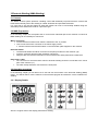
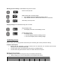
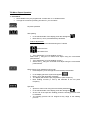
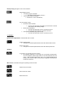
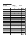
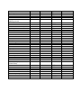
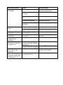
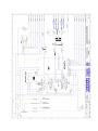
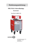
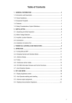
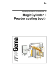
1
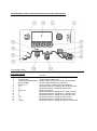
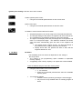
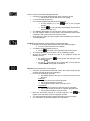
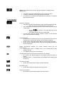
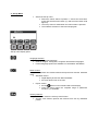
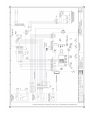
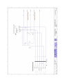
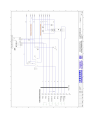
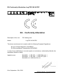
USER MANUAL LogiTIG 220 AC/DC 240 AC/DC 300 AC/DC MERKLE welding units are premium quality capital equipment. As a manufacturer, we set the highest standards in the field of quality and reliability. Technical innovation and permanent further development are a natural progression by Merkle. Specialist knowledge is premise for the safe operation and handling of all welding equipment. Safety instructions are defined in detail. You as the responsible user are obliged to follow the instructions of the operating manual. The operating manual is addressed to qualified welding experts. Only skilled technical staff are authorised to carry out service and repair work. This documentation explains the safety instructions, the functions, the operation and the maintenance relating to your welding unit. In the appendix you will find tables with reference values for your instrument settings, schematic diagrams, conformity attestation and lists of important optional equipment and spare parts. The following safety instructions serve for your own and others safety as well as prevention of damage to your welding unit and working area. For this reason, please read the safety instruction thoroughly before starting and follow the safety instruction during your work. Protect yourself and your surroundings against arc loads! Arc loads can induce irreversible damage to your eyes as well as flash burns to your skin. For this reason you have to use a welding shield of the correct protection class and wear the correct inflammable clothing. Isolate or shield your work area to prevent physical damage to third parties. Arrange your work area to prevent risk of fire! Remove flammable objects out of your work area. Do not weld in an area containing a flammable atmosphere. Make sure that fires can be safely and quickly extinguished (fire drencher, fire blanket). Pay attention to the handling of the gas cylinders! Gas cylinders have to be mounted in a proper mount and secured against the risk of tipping. Gas cylinders with damaged or leaky valves are to be immediately deemed unfit for use and returned to the supplier. Gas cylinders are only to be transported with valve safety caps in place. After finishing welding, all cylinder valves are to be closed. Do not operate the machine in wet surroundings! Induced humidity or liquid precipitation can cause electric shock and damage to your machine. Safety instructions before use The welding unit is built to recognized European safety standards. Safe working is nevertheless only possible if you read and entirely obey the operating instructions and the safety regulations. Installation is only to be performed by trained staff from Merkle establishments or appointed Merkle sales partners. Accident prevention The accident prevention regulations applied for this welding unit: BGR 500 section 2.26 (earlier VGB 15) *welding, cutting and allied processes A copy of this regulation should be readily accessible in every welding shop. The stipulations of this regulation are to be observed in the interests of safe and correct welding operation. * Available from the trade association responsible or Carl Heymanns-Verlag, Luxemburger Straße 449, 50939 Cologne. Safety instructions This unit is manufactured according to the requirements and stipulations of EN 60974.1 / VDE 0544 part 1. BGR 500 (earlier VBG 15) of the trade association for engineering and electrical engineering is also valid. Welding, cutting and allied working process 1) In case of an accident, disconnect the mains power supply from the welding power source immediately. 2) In the case of a short circuit to the main housing of the welding equipment, disconnect the welding unit immediately from the mains power supply and seek assistance from trained and qualified service personal or our service department. 3) Before carrying out repair or service work, the welding equipment must always be disconnected from the mains power supply. Be aware that capacitors may still be fully charged although the equipment is disconnected from the mains supply. Information on capacitor discharge procedures is available on request. 4) Repair work may only be carried out by a skilled and trained electrician, or by our service Department. 5) Before each use, check your equipment (machine, electrical and cooling fluid connections, welding torch, earth lead, pressure reducer) for external damage and function. If found to be damaged or inoperable, replace immediately. 6) Personal protective equipment in accordance with DIN EN 175, DIN EN 379 and DIN EN 169.The user has to protect his complete body, face and eyes against radiation and burns through correct protective clothing and equipment during welding. During operation, welding gauntlets, aprons, welding shield with protective filter (DIN EN 470-1 and BGR 189) are mandatory. Closed safety shoes are to be worn at all times. When welding in overhead positions, head protection is to be worn. Synthetic clothing or open shoes are forbidden. All protective equipment must be in accordance with the aforesaid and recognized standards. As additional protection for the eyes against UV radiation, safety goggles with side shields and corresponding face protection in accordance with BGR 192 and BGI 553 must be worn. Accident prevention regulation BGR 500 stipulates that it is the responsibility of the employer to provide suitable personal protective equipment, while § 28 stipulates that it is the responsibility of the employee to wear suitable clothing. 7) Protection during welding with increased electrical hazard. Welding rectifiers and welding power sources suitable for welding with increased electrical hazard, must, according to EN 60974-1 and BGI 534 be stamped with the „S“ sign to indicate this. Use insulating materials and mats against electrical conductance or contact with wet floors. You have to wear dry and undamaged work clothes as well gauntlets and shoes with electrically insulating rubber soles. Vent all rooms where welding takes place, install suitable fume extraction devices and wear fume/dust masks if necessary (see detailed statement BGR 500 and BGI 533 section 5). 8) In order to prevent stray currents and the effects thereof (e.g. destruction of electrical protective ground conductors), the welding return cable (workpiece cable) must be connected directly to the workpiece to be welded or to the table (e.g. welding table, grid Model welding table, workbench), supporting the workpiece (see BGR 500). When installing the ground connection, assure that there is a good electrical contact (remove rust, paint, etc.). 9) During the welding pauses, the welding torch is to be laid down on an insulated surface or suspended in such a way that it is not in contact with the workpiece and the torch support is connected to the welding power source (see BGR 500). In the case of longer work pauses, the welding unit must be switched off and the gas cylinder valve must be closed. 10) The shielding cylinder must always be secured against falling using a suitable mount/frame and securing device (chain or belt). 11) Under no circumstances may the unit be put into operation while it is opened. Apart from safety regulations, sufficient cooling of the electrical components provided by the fan cannot be guaranteed. 12) In accordance with BGR 500, persons in the vicinity of the welding arc must also be informed of the hazards and protected against them. Safety partitions (“welding safety curtains”) must be erected in accordance with DIN EN 1598. 13) No welding work may be carried out on containers in which gases, fuels mineral oils or similar substances have been stored (explosion hazard). See §31 UVV BGR 500Even if they have been empty for a long time See § 31 of accident prevention regulation BGR 500. 14) Welds which are subjected to high loads and which need to meet specific safety requirements may only be performed by specially trained and qualified welders. 15) Never bring the welding torch to your face. Should the torch trigger be inadvertently operated, risk of injury through the projecting welding wire is highly possible. 16) In areas of high fire risk, the welder must obtain a welding permit and have this on his person throughout the duration of the welding work. On completion of welding, a fireguard must be delegated to ensure fire protection until the welds have cooled sufficiently that any fire hazard is eliminated. 17) Ventilation measures must be applied in accordance with BGI 553 section 9. 18) The potential hazard to eyesight must be clearly indicated by means of a sign at the workplace „Caution! Do not look into the arc!” 19) It is only permissible to fit welding wire spools or change wire feeding rollers/components of the wire feeding mechanism with the welding unit disconnected from the main electrical power supply. When inching the welding wire through the torch hose package after a spool change, ensure that the wire feeder housing door is closed at all times. !!!Danger of injury to hands through rotating components!!! The duty cycle measurements have been carried out in accordance with EN 60974-1 / VDE 0544 part 1 (10 min working period). 60 % duty cycle means: After 6 minutes welding period, a welding pause of 4 minutes is necessary. The electrical components in the welding unit are thermally protected against overheating. Filter attachment Should a filter attachment option be available for your welding unit, then the use of this can reduce the effective duty cycle of the machine (reduced air flow). Regular replacement of the filter insert is necessary not to reduce the duty cycle even further. The frequency of replacement/cleaning is dependent on the conditions in your working area and cannot be generally set. Only replacement filter mats with the article number 005.0.1048 are to be used. !!! Using other filter materials than that stated above will lead to a loss of guarantee!!! Evaluation of the installation site Before installing the welding equipment, the user must evaluate potential electromagnetic problems in the vicinity. The following must be considered: Other power cables, signal and telecommunication cables above, below and next to the welding equipment/area. Radio and television transmitters and receivers. Computer and other control devices. The health of other peoples in the vicinity, for example if pacemakers and hearing aids are being used. Calibration and measuring equipment Interference immunity of other devices in the vicinity. The user must ensure the electromagnetic compatibility of other devices used in the vicinity. This may require additional safety measures. Instructions to avoid electrical interference The welding unit has been manufactured in accordance with the requirements of guideline EN 50199 regarding electromagnetic compatibility. It is nonetheless the responsibility of the user to ensure that the welding equipment is installed and operated in accordance with the manufacturer instructions. If electromagnetic interference is detected, it is the responsibility of the user of the welding equipment to find a solution with the technical assistance of the manufacturer. In some cases, it may be sufficient simply to ensure a good earth return for the welding current (earth lead correctly installed). In other cases, it may be necessary to build a complete shield for the welding power source and workpiece using the input filters. In all cases, electromagnetic interference must be reduced to a minimum to avoid possible malfunctions. Note: For safety reasons, the welding current circuit may or may not be grounded. No modifications may be made to the grounding without the approval of an expert who is able to determine whether the changes might increase the risk of accidents, e.g. by allowing parallel welding current return paths which could destroy the ground conductors of other equipment. Further instructions are contained in TEC 974-XX "Arc welding equipment – installation and use". Procedures to reduce emitted interference a) Mains supply Welding equipment is to be connected to the mains in compliance with the recommendations of the manufacturer. If interference occurs, it may be necessary to take additional precautions, e.g. filters for the mains connection. Make sure that the power cable of welding equipment is installed in a fixed position shielded by means of a metal conduit or similar. The entire length of the shield must be electrically grounded. The shield must be connected to the welding power source in the way to obtain a good electrical contact between the metal conduit and the housing of the welding unit. b) Equipotential compensation The electrical connection and grounding of all metallic components or parts in the direct welding vicinity should be taken into consideration. Metallic parts connected to the workpiece can, however, increase the risk of the welder receiving an electric shock by touching these metallic parts and the electrode simultaneously. The welder must be electrically insulated against all connected metallic parts. c) Grounding the workpiece If the workpiece is not connected to the ground for electrical safety reasons, or due to the size and position of the workpiece, e.g. steel structure or outer wall of a ship, grounding the workpiece may in some cases, but not all, reduce emitted interference. It must be ensured that grounding the workpiece will not increase the risk of accidents for the user and cannot cause the destruction of other electrical equipment. If necessary, the grounding of the workpiece must be carried out by means of a direct connection to the workpiece. In countries where a direct connection is prohibited, the connection must be made by means of suitable inductive resistors, selected in accordance with national regulations. d) Shielding Selective shielding of other cables and devices in the vicinity can reduce interference problems. For special applications, it may be worth considering shielding the entire welding system e) Welding Cables Welding cables should be kept as short as possible and routed close together on or near the floor. Maintenance of the welding equipment Welding equipment must be maintained regularly in accordance with the recommendations of the manufacturer. All access and service doors and covers must be closed and fastened securely when the welding equipment is in operation. No modifications whatsoever may be made to welding equipment with the exception of modifications and adjustments specified in the manufacturer´s operating instructions Introduction The welding equipment must be firmly positioned and secured against tipping or rolling. All air intakes on the unit must be clean and free from obstruction to prevent the risk of overheating. Ensure that no metallic particles can be transported along with cooling air into the welding unit. These are firstly abrasive and will accelerate the wear of mechanical moving components, and are electrically conductive and can lead to internal short circuits on electrical components/PCBs. Attention! If extension cable are used: Only use cables with single strand diameters of at least 2.5 mm². Unroll the entire cable drum (hazard of overheating) Attention! If the welding unit is to be powered by an electrical generator: The available power output of the generator must be at least 10% greater than the maximal power input of the welding unit. (Available output of a generator is dependent on current draw from other connected devices. This is to be taken into consideration when connecting your welding unit) The open circuit voltage of the generator must be regulated. Voltage peaks from unregulated generators may be harmful to your welding unit. 1. The LogiTIG 220 AC/DC, 240 AC/DC and 300 AC/DC The LogiTIG 220 AC/DC, 240 AC/DC and 300 AC/DC and are equipped with top of the line inverter technology, they are designed to carry out the TIG and MMA welding processes in both AC and DC current. The welding machine is universally employable. This series of machines lends itself well to on sight welding work. This is thanks high level of mobility due to its extremely compact (space saving) design and reduced weight characteristics, this coupled with the fact that it can also be run on a single phase 230 V system (180 A max) 1.1 Intended Purpose This welding equipment it designed for the following processes MMA welding TIG welding with a shielding gas All other processes undertaken with this machine are strongly ill advised and should not be practised. 1.2 Transport Before transporting this machine disconnect the gas line between the gas bottle and the welding machine. During the transport make sure that the machine is secured in case of an accident. DANGER: The gas bottle must be removed for the purpose of transportation. If not removed there is a danger of injury through falling gas bottles. DANGER OF EXPLOSION 1.3 Positioning in the work place The machine should be placed in dry ambient areas and is designed only to be used in covered protected environment. Note: Never weld in open areas in the rain. Always check the proposed area for EMV activity Should there be any disturbances then these must be eliminated before any welding can take place. Danger is also present through electrically conductive components Isolation matting should be available for the protection of the operator from electric shocks 1.3.1. Positioning Attention Cooling fans are employed in this machine to cool the power unit, therefore it is imperative that: Fresh air is allowed easy access to entry point (front) of the machine and the exiting air is also free of any constricting obstacles. There should be an all round free space of approx. 80cm around the machine. In workshops with a high dust concentration an air filter should be employed on the machine (optional extra). The machine should be placed on firm even ground. Ensure that the machine entry temperature is between -10 and +40°C Care should be taken to ensure that the rooms humidity is correct (up to 50% at 40°C and 90% at 20°C). The surrounding environment should be where possible free of excessive dust, acid and corrosive gases. By higher concentrations of the above an air filter must be employed. 1.3.2. Use in conjunction with a power generator The power output of the generator should be at least 10% higher than the power intake of the welding machine. The output voltage of the generator must also have a regulated open circuit voltage. Switching on First start the power generator and then switch on the welding machine. Switching off First switch off the welding machine and then the power generator. By not adhering to the above advice YOU take the risk of damaging the machine through power spikes. 1.3.3 Extension cables Cautionary measures in the use of extension cables: The cable should be in a good and safe condition. The cable should always be fully removed from the cable drum. The maximum cable length should not exceed the conductor cross section value. When these rules are not adhered to there is a real risk of overheating. 1.4 Start up Procedure During the start-up process information about your machine is displayed on the Multi-Functional display. You can according to the machine version various settings can be carried out. Start Process Turn the main power switch to position “I”. The software will be loaded and the Multi-Functional display (MFD) will show the following information: - Display version - Machine version - The last selected welding program During the start up process no setting changes can be made! In the factory delivered condition the welding unit is set in “standard mode”. In this condition the basic welding parameters are available. The operation is also simple. Should you require more functions than are presently available then the machine can be switched to an “expert Mode”. The procedure for this is explained in “Set-up menu” (chapter 7) Special functions Resetting to factory settings (see Chapter 8) Reset process explanation Colour adjustment of the MFD panel: Select set-up menu Press button I1 The display panel background and script colour can be changed, i.e. black/white to white/black Actual Welding Parameter will show all welding conditions one after the other Press buttons I1 and I2 together for 2 seconds. HIGH CURRENT / BIPOWER Technology (only LogiTIG 240 AC/DC) According to the power supply the maximum output available: Mains connection to 3 Ph 400 V-N-PE (32A): TIG welding current up to 240A MMA welding up to 220A With adapter 400/230V (16A) TIG welding current up to 180A MMA welding current up to 160A limited Duty Cycle (dc) The Duty Cycle measurement is carried out according to EN 60974-1 / VDE 0544 in 10 Minute working cycles. This has a value of 60% dc: After a 6 minute welding period there must follow a 4 minute cooling phase. The performance parts are Temperature controlled against overheating, after they have switched off they will automatically re-activate when the temperature drops. These values apply to working temperatures up to 40 °C and a maximum height above sea of 1000m NN. Higher temperatures, attached air filters and higher altitudes will affect the duty cycle values. 1.5 Illustration of the control panel and accessories attachments Front panel controls Position Sign 1 Menu button 2 Display Panel 3 Incremental potentiometer 4 Status Display 5 Buttons 1-4 6 tdown 7 Iend 8 Gas Test 9 I2 10 I1 11 tgas 12 Istart 13 tup 14 t1 and t2 Function___________________________________ button for Menu Functions (only in expert mode) shows Welding parameters endless rotary control for the setting of parameters machine status and Warning indicators function buttons, module and menu functions parameter buttons for setting of the down slope time parameter button for setting the end current button for Gas test nd parameter button for setting the 2 welding current st parameter button for setting the 1 welding current parameter button for setting the pre-gas flow time parameter button for setting the start current parameter button for setting the upslope time parameter button for setting the I1and I2 current times LED status/warning display Position Sign 4a Machine status display 4b Network connection 4c Warning light temperature 4d Defect warning light Connection adapters Position Sign 15 control cable 16 control cable 17 - Pole Busch MMA electrode holder 18 + Pole Busch Function _________________________________ shows the machine has no-load current at the Poles shows that the machine is switched on shows that the machine is overheating shows that the machine has a defect Function ____________________________ remote control torch control TCG connection: combined Gas, TIG current and Earth cable and MMA electrode holder connection Display panel Position Sign 19 text field 20 parameter displays 21 flag display field right 22 pictogram line 23 AC – balance scale 24 flag display field left Function ____________________________ shows the parameter mode shows the actual parameter value selected shows the activated flags shows the selectable menus/modus functions graphic display for the AC balance value shows the activated flags 1.6 operation control in standard mode The following diagrams clarify the function and pictogram in the display panel when used in the standard mode of the welding unit. Control button illustrations to be imported from the original document Function buttons F1, F2, F3, and F4 for: Selection of the mode in connection with the pictogram on the display, through the repeated use of the buttons. Selection of the parameters according to the pictogram in the display and the adjustment of the values using the incremental switch. Menu button (in standard mode inaccessible) button for selection of the menu function Incremental potentiometer continuous potentiometer without rotary limiter adjustment of the value of the selected parameter Parameter button (PB) for the direct adjustment of the main welding current I1. Integrated into the button is an LED. The LED button lights up: When the current I1 is being adjusted When the current I1 is active in the welding process If the main welding current I1 is adjusted, at the same time the welding current I2 will adjust itself proportionately. Parameter button (PB) for the adjustment of the welding current I 2. Integrated into the button is an LED. The LED button lights up: When current I2 is being adjusted When the current I2 is active in the welding process Should the I2 current be altered, it will have no effect on the main welding current I1. The welding current I2 is only available in the following processes Slow pulsing Quick pulsing 4-stroke with current I2 PB for the selection of the down slope tdown. Integrated into the button is an LED. The down slope time of the welding current I1 until the end current is activated Iend Welding process with 2 welding currents I1 and I2: Both welding currents near themselves in the selected time of the end current Iend The function is active in: Pulse-setting Stroke-modus PB for the selection of the end current Iend. Integrated into the button is an LED. In the selected time the active welding current will be reduced until it reaches the Iend current value. PB “Gas-test”. Integrated into the button is an LED. Setting the gas post flow Press button once LED in button will light up Post gas time can be set using the incremental parameter Selecting the gas test function Press the button twice LED in button will blink The gas valve will open The timer will run backwards The gas valve will be closed automatically on reaching zero The gas valve can be manually closed by pressing the button once more After the completion of the gas test The LED in the button will stay lit Then the gas post flow can be set using the incremental potentiometer (as described in “gas post flow”) Displaying the gas post flow function After the welding process has ended The LED button will blink The gas post flow will continue for the selected time Automatic purging of the gas line will follow: When switching from MMA mode to TIG mode, when the electrode is used. During the running up of the welding unit whilst in TIG mode. Warning light indicators Welding unit status indicator LED is lit No load current is at the connecter bushes Network connection status indicator LED lights up when: The welding unit is connected to a mains adapter The mains switch is switched on Warning light – overheating of the power components LED will blink when: The working temperature is 5°C before its critical limit is reached Advance warning that the welding process will be automatically interrupted LED is constantly lit Overheating temperature has been reached Before the welding process: No welding process will be available until the unit has cooled to a normal working temperature During the TIG welding process: In 2-stroke and 4-stroke mode the welding current will be reduced until it reaches the end currant. The welding process will only be interrupted when the end current is reached With a foot control and an automated or robot unit the program will be interrupted without the down slope process being activated Remote controls: if one of the following is in use: torch trigger or foot control, the display panel will show the following defect message, “release trigger” During the MMA welding process : The welding process will be immediately interrupted Defect warning light This LED illuminates when there is a defect in the machine: Before the welding process has begun No welding process possible During the TIG and MMA welding process Welding process will be immediately interrupted Warning lights and fault messages in the display unit “Release the trigger” One of the following control elements is in use Torch trigger, foot switch or control contact “Water pressure failure” Flag Symbol HOLD flag after the end of a welding process. The flag symbol shows the user that the welding parameters used have been saved. The storage of the information is transient, After an interruption the welding process will re-begin with the same parameters. Every parameter changed wipes the previously stored parameter from the parameter settings. The recalling of the previous weld settings through the machine is then not possible. TIG welding parameters The chosen parameters of the last used cycle before the Down slope Tdown will be saved by the machines memory. AC – Balance Scale (The display is visible in conjunction with the TIG Modus function “AC– Balance Amplitude”) The display is only visible in AC modus The vertical display represents the percentual share of the positive half wave during the complete welding process (in time). Indicator is positioned in the middle. The positive and negative share of the wave is identical. The indicator is positioned in the upper half of the scale The positive half wave is larger than the negative half wave Indicator in the lower half of the scale The negative half wave is larger than the positive half wave. One Pixel in the Horizontal translates to an adjustment of 3%. 2. TIG Welding TIG Stands for Tungsten-inert-gas welding. 2.1 Process A non consumable electrode made of tungsten or a tungsten alloy produces a welding arc. The welding arc burns between the electrode and the work piece and is protected by an inert shielding gas. The electrode and the molten pool are protected from the oxidising effects of the oxygen. The inert gases used for this process are Argon; sometimes Helium or a mixture gas containing both components can also be used. The filler material is manually fed into the weld pool for manual welding process and mechanically in the case of cold wire feed units. 2.2 Employment of the Process The TIG process can be found employed joining foil and thin sheet together between 0.3 – 4.0mm in one run, it is also used to join thicker pieces of material together (up to 12mm) when it can be simultaneously welded from both sides. Thicker material would only be joined using the TIG process when special technical demands dictate that TIG is the only process permit-able. The TIG process produces a very high quality weld bead. The process therefore lends itself to automatic welding as the process is easily controllable. In conjunction with special weld preparations the process can be used on thicker materials for carrying out the root run. The remainder fill and capping runs would be carried out using the MIG/MAG and Pulse-arc process. 2.3 Connection to the Mains Mains connector Make sure that the machines main switch is in the “0” position The male connector is securely plugged into the correct mains current Torch and hose assembly Combination connector (TGC-connector) must be connected to the minus pole (17) connector. º Turn the connector clockwise through 180 to ensure secure connection. The control socket should be connected plugged into socket 16 and secured using by turning the twist connector until secure. Earth return lead The earth return lead should be connected to the plus pole connector and turned through 180º to secure. The earth clamp should then be secured to the work piece. Gas bottle connection Lay the correct spanner for connecting the regulator within easy reach of the bottle. Remove the protective valve cap from the bottle. The gas valve should then be purged to remove all foreign bodies from the valve area. The gas pressure gauge connection should then be checked to see that it is also clean. The gas pressure gauge can now be screwed to the bottle and secured tightly using the spanner. Make sure that the gasket ring in the valve nut is securely in place and not damaged in any way. If so then replace with a new one. 2.4 Joint preparation The TIG process requires that the weld joint is dry and free from grease and oil or any other sort of dirt contamination. The necessary edge preparation depends on the thickness and the position of the weld along with the job itself. These conditions are standardized in DIN 8552, part 1. 2.5 Gas nozzle and welding current During the welding process using a shielding gas it is essential that the weld pool is covered with the Argon gas and therefore protected from the harmful effects of contamination (oxidization) from normal air in the shielding gas area. To guarantee such welding conditions the following parameters must be finely tuned: Gas Flow Gas nozzle size Required welding current Extreme care needs to be taken to avoid gas turbulence as this phenomenon has the undesired effect of allowing air into the protective gas mantle. Using a standard gas nozzle does not always guarantee turbulence free welding. Using the so called “Gas lens” a special nozzle is used to allow the gas to flow freely without any turbulence. The gas lens concentrates the gas flow in such a way that it allows a greater gap between the work piece and welding torch. This in turn allows the tungsten electrode to be fixed with a protrusion of up to 10mm outside the gas nozzle. This then allows the easy access of corners and other difficult to get to joints. Through a longer protrusion of the weld electrode the dead spot becomes smaller and the view of the weld pool is greatly improved. The “gas lens” also allows under the same current conditions a much reduced gas consumption. Using the TIG process the optimal setting of the welding current is especially important; the end of the tungsten electrode must be equally burdened: Using a current too low for the tungsten electrode, the arc is not able to cover the complete tip of the electrode and therefore wanders on the tip and is not stable which in turn affects the weld process. Contrarily the overloading of the electrode causes it to melt, so that tungsten can be transferred to the weld pool. The inclusion of Tungsten in the weld pool is a weld defect that should be removed and redone. 2.6 TIG mode (standard operation) In the following chapter you will learn about how to operate the machine in the standard mode. At the end you will be able to use machine in the standard TIG process and also correctly set your own welding conditions. 2.7 Setting the welding current Before the start of the welding process Select the required welding current through the incremental potentiometer dial (3) This indicated value is 100% and is displayed on the display in Amperes. During the welding process The operator has several methods available to adjust the weld current. Through the incremental potentiometer (3) Using a remote control unit; Torch potentiometer Hand remote control Foot remote control The current value set using the incremental potentiometer automatically determines the end value for the hand potentiometer. During the welding process the display shows the value of the condition set using the remote control system. A change through the use of the remote control varies the welding current between 0% and 100% in reference to the incremental potentiometer selected welding current. The display shows the ampere value of the welding current. Welding current after interruption Interruption <5 s: The last selected conditions (on the incremental potentiometer or remote control) would be reselected Interruption >5 s:(forced interruption) The welding current will return to the value last selected through the incremental potentiometer. 2.7.1 TIG welding application 2-stroke operation During the complete welding program the torch trigger must be kept pressed, after the release of the trigger the selected down slope program is engaged, after that the selected gas post flow. Select the F1 button on the front panel Torch trigger press and hold The torch will ignite The welding process will start with welding current I1 Release the torch trigger The down slope LED will light up (I1 LED extinguishes) After the down slope program has run the LED will be extinguished The welding program is ended The gas test LED will light up The gas post flow will now activate Gas test LED is extinguished, the post flow gas is ended Note: During the ending of the welding process in the 2-stroke operation, the end current I end is not activated. 4-stroke operation With the pressing of the trigger the start current (Istart) is activated, after it is released the up slope (t up) is introduced as programmed until the welding current has reached the requested setting (I 1). If the torch trigger is then pressed again then the down slope (tdown) is activated until the end current (Iend) is reached. Once the trigger is then released the arc is extinguished and the post flow gas is activated. 4-Stroke operation with a secondary pulse welding current I 2 The trigger functions are the same as in the standard 4-stroke operation. The only difference occurs during the welding process whereby the quick pressing of the trigger activates the secondary pulse current I2, a repeated pressing of the trigger then returns the original welding current (I 1). If the trigger is depressed for longer than 0.5 seconds then the welding current down slope is activated and followed by the post gas flow. Manual Pulsing Press The torch trigger(TT): Arc is ignited The process is started with welding current I1 I1-LED on display panel will illuminate Press TT and release (<0,5 s): Current I2 will be activated I2 LED on display panel will illuminate (I1 LED will be extinguished) Press TT and release (< 0,5 s) Current I1 will be reactivated. I1 LED on display panel will be activated (I2 LED will be extinguished) TT press and Hold ( > 0,5 s) The down slope LED tdown will illuminate on the panel (I1 LED extinguished) After the tdown sequence has run the tdown LED will extinguish End current (Iend) LED is illuminated and the end current is active Release the TT End current LED is extinguished Welding process will be ended Gas post flow LED will be illuminated Gas post flow will be ended Gas post flow LED will be extinguished Gas post flow LED will be extinguished, the cooling process is ended 2.8 TIG Operation in standard mode 2.8.1 the DC welding mode With the TIG process mostly high alloyed steels are welded, generally speaking steel and copper can be welded with DC (direct) current. To avoid a critical thermal loading of the electrode, the welding torch should be connected to the Minus pole and the earth return lead to the plus pole of the machine. The temperature on the minus pole is ca. 3600°C, the plus pole is ca. 4200°C. When welding with DC current the electrode must be ground to a sharp point. The ignition can be realized with a torch angle of 15-25° from the vertical. By using bad practise methods (electrode comes into contact with the weld pool) the weld bead can become contaminated with tungsten inclusions, this is classed as a weld defect. When this occurs the contaminated electrode end should be broken off and a new point ground on the electrode. Overview of the TIG DC mode 2.8.2 Alternating current (AC) welding mode Using alternating current (AC) Aluminium, magnesium and their alloys can be successfully welded. The thermal loading of the tungsten electrode is much greater in the AC welding mode. During the half wave “electrode on minus pole” the work piece is warmed more than the electrode, during the half wave “electrode on plus pole” the area around the welding arc is electronically stripped of the surface oxides to allow problem free welding. With the correct conditions obtained for this welding process the electrode will form a ball at the end of the electrode. Overview of the TIG AC mode TIG mode in standard operation The method of operation can be selected by pressing button F1 until the desired method appears in the display. 2-Stroke operation (see also chapter 4.7.2) As long as the Torch trigger (TT) is depressed and held, the welding process is active When the TT is released and the welding current down slope is activated. 4-Stroke operation (see also chapter 4.7.2) By pressing the TT the welding current is activated By pressing and holding the TT, the down slope cycle is activated. 4-stroke operation with a second welding current I2 (see also chapter 4.7.2) Manual Pulsing between I1 and I2 Ignition method, select by pressing F2 until desired method is shown in display High frequency ignition The welding arc is ignited through a high frequency impulse without the need for contact between the work piece and electrode. Lift arc ignition This function is only available in the DC mode Operational procedure: Bring the electrode tip into contact with the work piece Press the TT and lift the torch away from the work piece The arc will automatically ignite The ignition is completed using minimal current. DC or AC welding process selected through the F3 button: Direct current operation Alternating current operation AC Balance selected through the F4 button AC balance amplitude The time difference between the positive and negative half wave is represented as a percentage. The cycle time and the frequency are not effected. The percentual part of the positive half wave within the whole wave is shown on the display. The difference remaining from the complete 100% is the percentual measure of the negative half wave. Display value shows 50%: the percentage time of the positive and negative half wave are identical. Display value shows 90%: the positive half wave percentage is 90%, the negative half wave value is 10%. Current setting I1 and I2, these values can be set through the parameter button I1 and I2 Press button I1 and with the incremental rotary switch select the desired welding current Press button I2 and with the incremental rotary switch select the desired secondary welding current 3 Electrode Welding (MMA Welding) 3.1 Process The Merkle inverter system produces a welding current with drastically improved harmonic content that lends itself extremely well to the welding of coated electrodes and specialist electrodes. It is now true to say that just about all weld able metals can now be successfully welded using the electrode process without the need for a protective gas. 3.2 MMA Preparation In the following chapter we will explain how to connect each individual part to the machine in order that MMA welding can successfully be carried out. Mains connection Ensure that the machines main switch is switched to the “0” position Now connect the mains connecter to the mains supply socket Please read the technical information on the information plate supplied on the machine. Electrode holder The Electrode holder should be connected to the plus pole Busch of the machine (18) Insert the connecter and then twist clockwise until secure Always make sure that the information in the manufacturers safety data sheet is adhered to Earth return cable The connector for the earth return lead for electrode welding should be connected to the minus pole of the machine (17) The earth clamp should be connected to the work piece 3.3 Operation procedure In the following chapter you will learn how to set and use the machine in the electrode welding (MMA) mode. You will be able to use the machine in the electrode program and select the correct conditions for welding. 3.3.1 Display Details Above is a typical view of the display panel before welding 3.3.2 Electrode welding mode Electrode Mode Display (MMA welding) MMA welding can be selected by pressing the F1 button until the symbol for MMA welding appears in the display: Electrode (MMA) welding The electrical circuit will be checked: When the machine is switched on in the MMA mode When the machine is switched from the TIG to the MMA process. If the welding circuit is proved to be complete the warning message “electrode is live” Welding current and time parameters can be selected by pressing the F2 button until desired setting is displayed. Set the desired potentiometer (3) MMA welding current using the incremental Hot start current For a guaranteed ignition of the MMA electrode The Hot start function increases the start current (Ihot) for a predetermined time (Thot) therefore ensuring that a smooth start is achieved to the welding process. Hot start time Shows the time that the increased current will flow for. Arc Force (current control regulation) Should the electrode come into contact with the weld pool during the welding process an increase the welding current will automatically take place. This form of current regulation ensures that the welding electrode does not stick to the work piece. Should this still occur then the current will automatically be reduced in order that the electrode does not overheat. Adjustment range: Minimum current is the welding current IEL The maximum current available is a maximum of 250% of the current IEL The max. current value is determined through the machine version. Welding current Polarity is selectable through the F3 button Direct current process MMA welding with reversed polarity Only available when the welding program is active Only available when the TEDAC face shield is not connected Alternating current process Display settings are selectable through the F4 button Single display mode The display shows the actual welding current Double display mode The display shows: The first display shows the welding current The second display shows welding voltage 3.4 Welding process Before starting the welding process ensure that you are wearing the correct protective clothing. Insertion of Electrode Ensure that the electrode is correctly inserted into the electrode; the uncoated end must be clamped into the electrode holder jaw. The electrode holder must always be rested in/on an isolated station. The electrode will ignite should it come into contact with the work piece. Welding current selection The welding current can be set using the rotary incremental potentiometer Before setting your current value please read the guide table below: Guidelines for Electrode Welding Electrode size 2 Current Reading 40-80 2,5 60-100 3,25 90-150 4 140-240 5 170-240 6 250-300 4. TIG – Expert Mode Your welding machine is actually capable of a lot more than has been explained. To enable the further functions the machine must be switched from the standard mode to the Expert mode. The instructions on how to switch over to the expert mode is described in chapter 7. In the expert mode the welder has the capability of further adjusting the welding parameters in 5 sub-menus; this enables an optimum setting of the welding parameters. TIG Menu selection: Press menu button 1 Sub-menu “1. Pulse Menu” is now active Continue to press button 1 until the desired sub-menu is reached Exiting the TIG menu is achieved by going through all the available sub menus to the beginning or simply by pressing by pressing button I 1. The software will return to the last used welding programme. 1 1 Puls 2 Start 3 DC 3 AC 4 Job 5 Nadel 2 3 4 Automatic Pulsing (only available to in the expert modus) Slow Pulsing (Available in AC and DC mode) Using the menu button select 1: Pulse menu Using button F1 select slow pulsing With button F2 select the time for t1 Using the incremental potentiometer select the time value for current I 1 Using button F3 select time for t2 Using the incremental potentiometer select the time value for current I2 Button F4 is used to select the required wave form: Hard wave form Soft wave form TT press and hold Arc ignition Welding process starts Welding current I1 and I2 pulse in the pre-programmed time I1-button LED and I2-button LED illuminate alternately Quick Pulsing (only available in DC mode) Using the Menu button select 1. Pulse menu: Using F1 select quick pulse mode With the incremental potentiometer set the desired pulse frequency Current I1 and I2 will alternate at the desired pre-programmed frequency TIG Menu Expert Operation 1. Pulse Menu Not available in the pre-programmed “4 stroke with I2” in standard mode Through the continuous pressing of button F1 you can select: No pulse operation Slow pulsing In the left hand side of the display panel this will appear Both LED’s (I1 and I2) will alternatively illuminate Further adjustments: The wave form can be selected using the F4 button Soft wave form Hard wave form Time adjustment (t1) of the welding current I1 Select time t1 using the F2 button and adjust using the incremental potentiometer Time adjustment (t2) of the welding current I2 Select time t2 using the F3 button and adjust using the incremental potentiometer Quick Pulsing (only available in DC mode) Pulse frequency is set through the incremental potentiometer In the display panel this symbol will appear Both I1 and I2 will illuminate constantly The display will show the pre-programmed pulse frequency Both welding currents (I1 and I2) will alternate at the set pulse frequency Spot time Spot time value is set using the incremental potentiometer In the left hand side of the display panel this will appear At the end of the spot time welding phase the welding process must be restarted The welding process can be stopped at any stage of the welding process The time value of the welding current I1 can be set using the F2 button: Time value of welding current I1 Set time value on the incremental potentiometer During time t1 current I1 is in operation Only selectable in the slow pulse mode The time value of the welding current I2 can be set using the F3 button: Time value of welding current I2 Set time value on the incremental potentiometer During time t2 current I2 is in operation Only selectable in the slow pulse mode Wave form selection is achieved through the pressing of the F4 button Soft flank wave form Only available in slow pulse The alternating between pulse currents I1 and I2 follows continuously. This prevents the build-up of noise in the arc during slow arc. Hard Flank wave form Only available in slow pulse mode The alternating between the active current s I1 and I2 has a very abrupt action. 2. Start Menu Gas pre flow time is selected using the F1 button The gas pre-flow time (tgas) is set using the incremental potentiometer Start current is selected with the F2 button: The start current (Istart) is set using the incremental potentiometer Up-slope time is selected with the F3 button The up-slope time is set using the incremental potentiometer Cross-over time (tup) from the start current (Istart) to the main welding current I1 Only active when no pulse program is in operation. Display setting through the use of the F4 button Single display-screen No Pulse program activated: The display shows welding current I1 When Pulse mode is activated : Shows the I1 and I2 alternatively Two row display screen No Pulse mode activated: The first row will show the welding current and the second row will show the welding voltage Slow Pulse is activated: The first row shows the current I1 and the second I2 The first row shows the time t1 and the second t2 Fast Pulse is activated (only in DC mode): The first row shows the current I1 and the second I2 3. DC Menu Ignition pulse adjustment is selected with the F3 button Positive ignition pulse Using the incremental potentiometer select the desired start current Ignition Pulse time Using the incremental potentiometer select the desired pulse time AC Menu AC frequency is selected with the F1 button The welding frequency is set using the incremental potentiometer. The AC frequency had a large effect on the weld bead and the arc noise. With currents larger than 100 A it is recommended that a frequency of 50 Hz is used in order that the amplitude of the weld arc is kept to a minimum. Wave Form is selectable through the pressing of the F2 button Square wave form mode Sinus wave form mode Mixed wave form Ignition pulse setting is with the use of the F3 button Positive ignition pulse current Using the incremental potentiometer set the current value Ignition Pulse time Using the incremental potentiometer set the time value AC balance can be selected with the F4 button 4. Job Menu Amplitude proportion can be set using the Incremental potentiometer The time percentage of the positive to negative half wave must be set. The complete time and therefore frequency cannot be changed. The figure in the display shows the percentage time of the positive half wave in a total period length. The difference between the shown value and 100% automatically gives the value of the negative half wave. The display shows a figure of 50%: the time percentage of the positive and the negative half wave are identical. Display shows 90%: the positive half wave is 90% and the negative half wave is 10%. Be Aware: The availability of the Job menus is dependent on the setting of the set-up menu. The number of job programming space available is dependant memory capacity A upgrading of the memory capacity is an option that is also available. There are different ways to select the memory banks Using the menu button on the control board: 4. Job selection Using the incremental potentiometer select the available memory space. Torch with two triggers select the memory banks by pressing the second trigger this process is only available when no welding program is active Save to memory the actual welding parameter Using the incremental potentiometer select a memory space the memory number will show in the display To save the program press F1 A successful programming will show itself through: a brief showing of a tick number next to the program the flag on the right side of the display (square with a program number in it) The welding parameters are now saved to chosen program number The old program details (if the program was previously used) will be overwritten and removed from the memory banks After exiting the menu this job program will be available to the user as a welding program Loading the selected job number with the saved parameters. Using the incremental potentiometer select the desired program. The job number will show in the display To load the saved condition press F2 the flag will show in the right hand side of the screen The set parameters are now set for use as a welding program Should the operator change any part of the program during the welding process: the program number the display panel the flag will replace the program flag to show that the operator is not working with a saved job in the square will extinguish from Removal of the parameters of a saved job Using the incremental potentiometer select the desired program (the program number will show in the display) To remove the program press F3 the display will then ask you to confirm the removal of the program Removal using F4 confirm the removal program the program has been removed the program will then return to the job-menu Cancellation by using the F2 button the removal can be cancelled the job will remain as the job no originally programmed the program will return to the job-menu After the successful removal of a saved program a tick appear for a short time next to the program number The removed program space will be replaced by a basic program The restoration of removed programs is not possible will Shows in an automatic run through, the saved program conditions in the display panel Using the incremental potentiometer select a program space To start the automatic run through press the F4 button The amount of conditions shown depends on the amount of conditions that have been saved 5. Electrode Menu Electrode (Tungsten) Using the Incremental potentiometer select the desired electrode size there are six pre-programmed sizes to choose from with inconsistencies between the size of the needle and the selected current value: the flag will appear in the right hand side of the display the welding process will not be interrupted The flag shows that the welding conditions chosen for the electrode are not recommended conditions Confirmation flag A short period of blinking at the end of programming shows that the machine has confirmed the changing of the welding conditions Shown by the confirmation button after the entering of the PIN code Shown by the confirmation button when removing welding parameters from a set program Shows discrepancies between the chosen welding current and the electrode size The program shows a condition that is not recommended for this welding program The welding process will not be affected The flag shows which version of the set up menu is in operation Full version: the flag will appear in the display during the switch on phase Standard version: no fag will appear in the display when switching the machine on The slow pulse flag Shows that a slow pulse program has been selected Fast pulsing flag Shows that a fast pulse program has been chosen Flag for spot welding Shows that a spot welding program has been chosen 5. Set-up Menu Select the set-up menu: Switch the mains switch to position “I” and at the same time press and hold the menu button (1) until the menu button LED lights up The set-up menu is exited when the menu button is pressed The software will return to the last used program Set-up menu display panel Language selection Using F1 select the desired language German, English, Portuguese, Hungarian and Russian languages Further language options are available on consultation with Merkle Menu Version Using F2 the operator can choose between the expert menu and the standard menu Standard version: Digital display shows text “Menu disabled” the menu button has no function Expert version the flag shows on the left hand side of the display using the menu button the complete range of parameter menus is now available Security features Using the F3 button select the security code function Security code function protects the machine from use by unwanted parties. PIN-code programming Warning: write down or remember your selected PIN-code The display will show “old PIN code” in display enter the old PIN code into the machine using the incremental potentiometer and confirm with the button under the arrow symbol Select “new PIN-code” in the display Enter a new PIN-code and confirm the new code by pressing the button under the arrow symbol Security code active After the machine has been switched on enter the correct PIN-code After the code has been accepted the machine is ready for use Correct code entered The software will start in the last programmed mode with all the parameters that were available during the last active phase of the machine. Wrong code entered Operator will be asked to re-enter the correct code Pin-code inactive After the completion of the switching on process the machine is ready to use. The software will start in the last chosen mode with the parameters that were active at the time of switching off Job setting Using the button F4 activate the job-menu Job function active Only available in the TIG expert mode Job function is inactive In the TIG expert mode the job is not selectable If the Job-menu is not activated in the set-up menu then the expert mode cannot be selected 6. Parameter adjustment range min = minimum max = maximum def = default (basic program) s = seconds A = Ampere ms = milliseconds Hz = Herz Description Short cut Adjustment range Adjustment value Hand welding arc Electrode welding IEL min def max 20 A 120 A 180/200/300 A Hot-Start time thot min def max 0,01 1,0 2,0 s s s Arc force Arcf min def max 100 150 250 %(respectiveIel) Anti-stick-current def 40 A Anti-stick-time def 1 A Ignition time min def max 2 10 100 ms ms ms Unit measure % % TIG-welding Start current Istart def 20 A Main welding current I1 min DC min AC def AC, DC 3 5 100 A A A Secondary welding current I2 Min def max 10 50 200 %(respectiveIel) def 20 A min 18 % (respective frequency) def max min max Adjustment range 40 82 25 60 Adjustment value % % % % End current Iend AC Balance Sinus Balance Description Short cut % % Unit measure Ignition pulse current Slow pulse time t1 for main welding current t1 min def max 20 80 150 A A A min 10 ms def max 500 2500 ms ms Ignition pulse current 2 t2 min def max 10 500 2500 ms ms ms Pre-flow Gas t gas min def max 0 0,4 2 s s s Post flow gas t gas min def max 0 10 25 s s s Up slope time tup min def max 0 0,4 2 s s s Down slope time tdown min def max 0 2 25 s s s min 50 Hz def max 100 200 Hz Hz AC-Frequency (Sinus-Mode) fix 50 Hz Pulse Frequency DC min def max 50 2000 12000 Hz Hz Hz AC Frequency (Hard and mixed wave) 7. Trouble shooting You will receive an overview of all possible faults . The messages in the display screen are mostly self explanatory and easily eliminated. Text in the display panel Warning lights on the display panel We have added a further category to our trouble shooting chapter, that of human error. Hear we have covered things that the operator may not have thought of before stating the welding process. Important: After each fault report and trouble shooting the machine must go through a complete restart in order to reset the machine. When the machine is switched off the operator must wait at least 3 seconds before restarting. Failure in Display Release trigger/button Cause Torch trigger activated Action Required Release trigger/button Foot switch activated Over voltage Control button activated Internal voltage supply Mains failure Electrode earthed Notify service agent Notify service agent The electrode has earthed and caused a complete welding circuit Elektrode aus dem Stromkreis entfernen When switching from TIG to electrode mode Electrode failure “Low water pressure” Alternating with “Refill water” and Failure LED is blinking “Internal failure” NTC failure When switching on the electrode mode The relationship of the chosen electrode diameter to the chosen current setting is wrong - No water pressure after the self testing phase Internal machine problem Select another electrode diameter Change the current to suit the electrode. Check water levels and refill as necessary - Check that the water pump is functioning - Check the complete water system - After the problem has been repaired restart machine Notify service agent Internal machine failure Notify service agent Failure in Display Menu locked Cause This function is dependant on the machine model Action required Press and hold the menu button when switching on the machine, release when button flashes Working temperature is 5°C before reaching over temperature Welding machine is over heated - Electrode overload Elektrode is Cold Over temperature light flashing Over temperature light illuminated Failure illuminated Failure flashes and the display shows alternately “water pressure failure” and “refill water” No arc ignition The MMA mode is not selectable and switches automatically over to TIG mode Mains over voltage/under voltage No action required Welding Process possible Leave the welding machine switched on - No welding Prozess possible - Automatic cooling system will engage until working temperature is reached. Warning light will extinguish and welding process can be restarted Test mains connector on another connection point Check Fuses - Switch the machine off and restart after 3 seconds Carry out instruction Pre-flow gas is et too high Reduce pre-flow gas setting Start current too low Increase the start current setting No gas shield Gas line and bottle need to be checked for fault Remove the electrode from the circuit The electrode has contacted to earth and caused a completion of the welding circuit Other observations Shielding gas flow interrupted Cause Gas bottle empty Flash back arrester activated The machine will not switch on Action required Gasflasche erneuern/austauschen Reset flash back arrester Pressure gauges set too low Increase setting Torch shroud blocked Clean torch shroud Gas line kinked and damaged Replace or repair gas line Main fuse defect Change the main fuse Internal current safety system active Torch trigger has no Control method is set to function foot controller Torch Potentiometer not Hand- / Foot regulator functioning connected In 4-stroke mode the Foot regulator is connected current I2 is not selectable By MMA welding the Only AC versins of this polarization cannot be machine offer this program reversed (-DC) Einstellung TEDAC shield is not recognised by the program In Expert mode the sub Job Menu deactivated menu “Job” is not selectable The machine becomes Cooling fans are turning in warm very quickly even the wrong direction though the cooling fans are functional Notify service agent De-activate the foot control De-activate hand- / Foot regulator De-activate the foot regulator Check the model type Remove TEDAC shield Select set-up menu and reactivate Job Function Notify service agent 8. Servicing The servicing schedule of the machine consists of a regular program of thorough cleaning and inspections. The regularity of these programs is directly linked to the usage and the working conditions of the work place. WARNING: before the any inspection or cleaning of the machine is undertaken: The time required to discharge the electrolytic capacitors must be adhered to, approx 30 minutes. The machine must be disconnected from the mains supply Allow the machine to cool down. Cleaning: De-greasing agent: only de-greasing agents recommended for electronic equipment may be used on this machine Remove top cover Dirt and dust to be removed with a vacuum cleaner Clean inner components Replace top cover and secure Inspection: Remove top cover Check the equipment for Used and discarded pieces of welding wire Loose connections Where necessary repair any problems Check the torch and hoses along with the euro connector for : Any areas that appear to have been damaged Where possible repair Replace and secure top cover 9. Wiring diagram LogiTIG 220/240/300 AC/DC EU-Conformity Attestation LogiTIG 220 AC/DC EU – Conformity Attestation Description of the unit: TIG Welding Unit Model: LogiTIG 220 AC/DC The above mentionned unit complies with the following European Regulations: EU-Low Voltage Regulation 73/23/EWG EU-Electromagnetic Compatibility 89/336/EWG In case of any modifications, incorrect repairs not exclusively authorized by Merkle, this attestation looses its valdity. Applied norms EN 60974 - 1 / IEC 974 - 1 / VDE 0544 part 1 EN 60204 - 1 / IEC 204 - 1 / VDE 0113 part 1 EN 60974-10 / VDE 0544 Teil 10 Kötz, September 12th, 2005 Wilhelm Merkle, Generalmanager Merkle Schweissanlagen-Technik GmbH EU-Conformity Attestation LogiTIG 240 AC/DC EU – Conformity Attestation Description of the unit: TIG Welding Unit Model: LogiTIG 240 AC/DC The above mentionned unit complies with the following European Regulations: EU-Low Voltage Regulation 73/23/EWG EU-Electromagnetic Compatibility 89/336/EWG In case of any modifications, incorrect repairs not exclusively authorized by Merkle, this attestation looses its valdity. Applied norms EN 60974 - 1 / IEC 974 - 1 / VDE 0544 part 1 EN 60204 - 1 / IEC 204 - 1 / VDE 0113 part 1 EN 60974-10 / VDE 0544 Teil 10 Kötz, September 12th, 2005 Wilhelm Merkle, Generalmanager Merkle Schweissanlagen-Technik GmbH EU-Conformity Attestation LogiTIG 300 AC/DC EU – Conformity Attestation Description of the unit: Model: TIG Welding Unit LogiTIG 300 AC/DC The above mentionned unit complies with the following European Regulations: EU-Low Voltage Regulation 73/23/EWG EU-Electromagnetic Compatibility 89/336/EWG In case of any modifications, incorrect repairs not exclusively authorized by Merkle, this attestation looses its valdity. Applied norms EN 60974 - 1 / IEC 974 - 1 / VDE 0544 part 1 EN 60204 - 1 / IEC 204 - 1 / VDE 0113 part 1 EN 60974-10 / VDE 0544 Teil 10 Kötz, January 11th, 2008 Wilhelm Merkle, Generalmanager Merkle Schweissanlagen-Technik GmbH Notes: Technical changes reserved 16. April 2012