1
DL-125C, DL-125CA
Installation Instructions
Programmable 2-Channel Speech Dialer
1. INTRODUCTION
1.1 General description
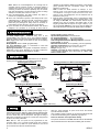
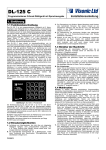
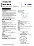
Numeric buttons
for programming
The DL-125C and DL-125CA are automatic programmable
speech dialer designed for verbal reporting of events.
B
1
Features
• 2 alarm inputs (Z-1 & Z-2).
• When each input is triggered, a specific prerecorded verbal
message is reported to 4 remote telephones.
• When an event occurs, it can be reported to different 4
telephones or (if both inputs are connected in parallel) to
different 8 telephones.
• The target telephone numbers may be frequently
reprogrammed by the user.
• If the telephone line is disconnected, the two output terminals
LF (solid state switch) are shorted or open (programmable).
These terminals can be used to send a signal to the alarm
system for telephone line failure indication.
• The alarm logic of each input can be programmed by the
installer (activation when alarm input is "open" or "closed").
• Selectable Pulse or DTMF dialing method.
• Certain functions can be performed in response to DTMF
control commands received from remote telephones.
• Whenever a message is acknowledged by the called party, a
highly sensitive microphone is activated, to allow the called
party to listen and hear sounds in the installation site.
• The "listening-in" period is limited in time, but the called party
can send a specific DTMF command to prolong it.
• Programmed data is retained in an EEPROM, unaffected by
power failures.
• A communication session with the first / second group of
telephones is initiated by triggering alarm inputs Z-1 / Z-2, or by
pressing AL-1 / AL-2 on the front panel, respectively.
• Powered by an external source and can be backed up by a
rechargeable battery.
Dialer Types
Dialing Can be Stopped by:
Pressing
Manual or Automatic
STOP button Power Disconnection
DL-125C
YES (*)
YES
DL-125CA
NO (**)
YES
* Provided that momentary alarm contacts are used.
** This feature is sometimes required by regulatory authorities.
Type
1.2 Applications
• Upgrading alarm control panels that do not have a dialer. Two
different events can be reported to remote telephones.
• Stand-alone 2-input 24-hour alarm system, triggered directly by
a smoke/shock detectors or a panic button (loop response time
200 ms).
• Looking after infants or old, sick and disabled people. The
dialer delivers a distress message and then allows the called
party to "listen in".
• Supervising unattended technical devices or processes, with
verbal reporting of equipment failures or process anomalies.
• Transmitting numeric reports to numeric pagers or voice
messages to voice pagers.
DE5817
2 - CHANNEL
AUTOMATIC
SPEECH DIALER
2
E
4
C
D
3
ALARM-1
F
5
PROGRAM
PROG
6
AL-1
ALARM-2
Dial
LED
7
8
A-F
DIAL
Model: DL-125c
*
9
AL-2
#
STOP
STOP
A
0
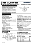
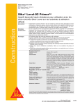
Programming
button
Z1 input
activation button
Z2 input
activation button
“STOP” dialing
button
Figure 1. Front Panel
1.3 Message Structure
The overall length of the speech message that can be recorded is
limited to 20 seconds (see par. 5,4) . Within this limit, the
message can be composed of two pre-recorded segments:
• The identification segment, common to both alarm inputs. This
segment usually identifies the user or the protected premises.
• The alarm type segment, associated with a specific alarm input.
This segment is used to describe the type of event reported
("fire", "intrusion", "panic", etc.).
A transmission initiated by a specific event (one of the two
alarms) is composed of the identification segment and one of
two alarm type segments. The order of transmission of the two
segments can be selected. For instance, you can select: "The
Smith residence, 25 Scarecrow Drive – Fire Alarm", or you can
select: "Fire Alarm – the Smith residence, 25 Scarecrow Drive".
1.4 Communication Routine
Note: In this section, location numbers identify "memory cells"
that retain programmed parameters (see Para. 5.8).
Once triggered into action, the dialer introduces a programmed
pre-dialing pause (see Location 14 in Para. 5.8). Then it
disconnects the local telephone set and engages the telephone
line. The DIAL LED lights and the process continues as follows:
A. The dialer starts dialing if uninterrupted tone is detected for 2
seconds (see C below). If 5 seconds elapse with no dial tone the dialer disengages the line, waits 5 seconds and tries
again. If another 5 seconds go by without dial tone, the dialing
procedure starts anyway (see B below).
B. The dialer checks whether a letter is programmed as a prefix
to the first telephone number. Letter prefixes impose an
additional delay before dialing (see Para. 5.2). The dialer
introduces the required delay (if any) and then starts dialing.
C. The dialer dials the programmed number. During dialing, the
LED either remains lighted (DTMF dialing) or flashes (pulse
dialing), depending on the dialing method selected. After
dialing, the dialer pauses for 5 seconds and transmits the
message prepared for the called party associated with the
input that had been triggered.
D. The dialer now waits 3 seconds for the called party to
acknowledge (the acknowledge signal is DTMF "1").
E. Upon receiving the acknowledge signal, the dialer removes
the presently contacted telephone from its task list for the
current event. If the "listen in" function is permitted (see
Location 10 in Para. 5.8) it will continue as in Paragraphs F
and G below. If not, the dialer will go "on hook" and proceed
to dial the next number.
1
Note: Without an acknowledgement, the message will be
repeated until the maximum number of message repeats is
reached (see Location 20 in Para. 5.8). The dialer will call the
remaining numbers and will then repeatedly retry the number
that didn't acknowledge, until the maximum number of dialing
attempts is reached (see Locations 12 and 13).
F. After acknowledgement, the dialer enables the "listen in"
function for a preprogrammed period.
G. At the end of the listen-in period, a short beep sounds. If the
called party keys "1" within 10 seconds, a new listen-in period
begins. Otherwise", the dialer will go "on hook". The listen-in
period may be prolonged as many times as necessary or
terminated at any time by keying "9" twice in succession.
H. Upon conclusion of the communication session with the first
telephone, the procedure in A through G above will be
repeated for all remaining telephone numbers in the relevant
group (provided that the "non-backup mode" has been
selected in Location 24).
Note: Location 24 allows selection of "backup" or "nonbackup" mode. In the backup mode, acknowledgement from
one telephone is enough to close the event. In the "nonbackup" mode, acknowledgement must be obtained from all
telephones in the group.
I. Once the entire communication cycle is concluded, the dialer
disengages the line and reverts to the standby state. If you
are using the DL-125C, the communication routine may be
aborted at any time by pressing the STOP button on the
keypad (provided that the input is no longer in alarm). If you
are using the DL-125CA, the only way to stop the dialer is to
disconnect the power, because the STOP button is disabled.
2. SPECIFICATIONS
Input Circuits: Two N.O. or N.C. inputs (programmable)
LF Alarm Output Type:
Solid-state relay, N.O. or N.C
(programmable), up to 100 mA / 30 V, ~30 Ω internal resistance.
(note: this output is comprised of two terminals that have no polarity)
Alarm Logic: Alarm upon circuit closure or upon circuit opening
(programmable)
Dialing Method: Pulse or DTMF (programmable)
Tel. Line Impedance: 600Ω, or customized to meet local
requirements in country of use.
Reporting Destinations: Two groups of telephone numbers, 4
telephones in each group. Reporting to one pager requires the
memory space dedicated to two telephone numbers.
Tel No. Length: 20 digits maximum.
Speech Message Duration: 20 seconds max.
No. of Dialing Attempts: 1 – 15 (programmable)
No. of Message Repeats: 1 – 255 (programmable)
Acknowledge Pause between Message Repeats: 3 seconds
Power Supply: 11-28 VDC
Maximum Current Drain: 20 mA (standby), 105 mA (operation)
Operating Temperatures: 0°C to 50°C (32°F to 122°F)
Size: 150 x 105 x 35 mm (5-7/8 x 4-1/8 x 1-3/8 in.)
Weight: 235 g (8.3 oz)
Standards: Compatible with RTTE requirements - Directive 1999/5/EC
of the European Parliament and of the Council of 9 March 1999.
EN50131 Grade 2 Class II.
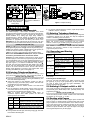
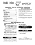
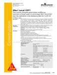
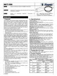
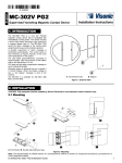
3. MOUNTING
The dialer may be installed as a stand-alone unit or within the
housing of a host system such as an alarm control panel.
Removing the Front Panel
Securing the Base to a Wall or Host System Cabinet
2
SEATS FOR FRAME TABS
Pull upward the bottom
frame to free the two tabs
and remove the frame
BASE
4
5
Open one of
the wiring
nockout and
perform wiring
(see section 3)
1
WIRING
KNOCKOUTS
SLOT FOR FRAME CATCH
Separating the Module from the Base
MODULE
SEATS FOR MODULE LEGS
Remounting the Module
RIGHT-HAND
LEGS (HIDDEN)
Swing up and
separate the module
from the base
MODULE
CATCH
Insert screws
via mounting
holes and fasten
the base to
mounting surface
MODULE
CATCH
Press slightly
to disengage
3
MOUNTING
HOLE
(1 OF 3)
6
Remount the module
and the front panel
(see step 1)
RIGHT-HAND
LEGS (HIDDEN)
MODULE
CATCH
BASE
Figure 2. Mounting
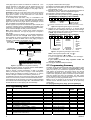
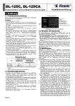
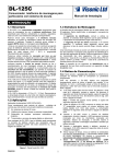
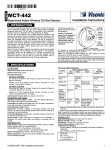
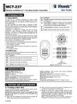
4. Wiring
The dialer can be powered by constant power supply or by a
switched power supply. When the dialer receives switched power
from an alarm system, it will be disabled upon stopping the alarm,
since the alarm relay cuts off the power. This type of wiring is
ideal when the dialer is mounted in a locked box that prevents
access to the STOP pushbutton.
Note: Both Z-1 and Z-2 inputs can be programmed as N.O.
(normally open) or N.C. (normally closed) inputs (see Locations
22 & 23 in Para. 5.8). With N.O. inputs selected, a short circuit
across the relevant input will activate the dialer.
2
With N.C. inputs selected, an open circuit across the relevant
input will activate the dialer.
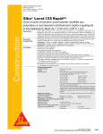
Use 15 AWG or larger conductor to connect the EARTH terminal
to the nearest electrical ground, preferably a ground rod.
Failure to earth the unit compromises safety!
The phone connected to the SET terminals will be automatically
disconnected from the line whenever the dialer goes into action.
DE5817
DL-125C or DL-125CA
+
–
12V-24V Z-1 Z-2
–
DL-125C or DL-125CA
+
–
12V-24V Z-1 Z-2
LF
Tel.
line
failure
+ –
12-24VDC
POWER
SUPPLY
N.O.
ALARM
RELAY
ALARM SYSTEM
–
Tel. line
failure
12-24VDC
alarm output
ALARM SYSTEM
TEL. LINE
JACK
LF
DL-125C or
DL-125CA
GROUND
ROD
RED
The input in use
is bridged to the
[–], provided that
the inputs have
been defined as
normally open
(N.O.).
Figure 3A. Connection to an Figure 3B. Connection to an
Alarm System with Constant Alarm System's Bell/Alarm
Output
Power Supply (Manual
Dialing Stop)
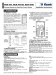
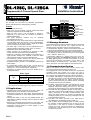
RJ-31X JACK
GRAY
GREEN
BROWN
GREY
4
SWITCHED LINE
2 1
RED
RJ-31X
5
TEL. SET
RJ-31X
CORD
FOR ALL COUNTRIES
EXCEPT NORTH
AMERICA
3
6
7 8
8-POSITION
RJ-31X PLUG
LINE
FROM
STREET
GRN
BROWN
FOR INSTALLATIONS IN NORTH AMERICA ONLY
Figure 4. Telephone Wiring
5. PROGRAMMING
5.1 Programming Fundamentals
The dialer employs a non-volatile EEPROM, that stores
programmed data and keeps it intact even during power failures.
Programming is carried out from the keypad by entering the
desired variables or by setting logic flags. Every variable is
programmed into a specific location in the memory, and each
location is identified by a LOCATION NUMBER. A set of default
parameters is programmed at the factory and saved in the
EEPROM, but you may change these at will (see Para. 5.8). The
programming format consists of the following successive entries:
[PROG] <LOC> [#] <VAL> [#]
[PROG] and [#] are keys provided on the keypad. [PROG] starts
the programming sequence and [#] confirms the preceding entry.
<LOC> is the location number. A leading zero may be ignored, so
Location 06 may be entered as a single digit – <6>.
<VAL> is the value or code entered into the selected location.
Refer to the PROGRAMMING CHART (Para. 5.8) for a full list
of locations, permissible entries and function details.
Caution! If an invalid parameter is entered at any stage, the LED
will flash rapidly for 2 seconds and programming will be aborted.
You will sometimes have to key the hexadecimal digits B, C, D
and E (see Para. 5.2 and 5.6). These digits are marked on certain
keys (see Figure 1). To start the hexadecimal mode, press [∗].
The DIAL LED near the keyboard will flash rapidly. Next, press
the key with the desired letter. The keypad will automatically
revert to its normal numerical function, and the LED will stop
flashing. Press [∗] again if you wish to key another letter. Voice
recording instructions are given in Paragraph 5.4.
5.2 Entering Telephone Numbers
Telephone numbers are entered in locations 1 through 4 (1st
group) and 5 through 8 (2nd group). The programming format is:
[PROG] <LOC> [#] <NUM.> [#]
A. Enter the programming mode by pressing the PROG key. The
DIAL LED should light steadily.
B. Select the location for the telephone number you wish to
program by keying its location (LOC) number. The DIAL LED
should flash once for each keystroke.
C. Press [#] to confirm the location number. The LED should
flash twice.
D. Key the telephone number (NUM), digit by digit. The DIAL
LED should flash once for each digit. There is a 20-digit limit,
including inter-digit pauses (see following note).
Note: To program pauses between dialed digits, as
sometimes required when PABX systems are used, the
following entries are available:
Key
Resultant Function
Code
Letter Strokes
wait 5 seconds or wait for dial tone,
B
[∗][1]
whichever comes first, and continue dialing.
wait 10 seconds and continue dialing.
C
[∗][2]
wait 5 seconds for dial tone and
D
[∗][3]
disengage the line if none is received.
After pressing [∗], the LED indicator flashes until a letter key is
pressed.
E. Having entered the last digit, finish off by keying [#] .The DIAL
LED indicator will extinguish.
DE5817
F. To program another telephone number, repeat the procedure
outlined in steps A to E above.
5.3 Deleting Telephone Numbers
A telephone number location will "blank out" if you go through the
programming process as in B above but skip the telephone
number. The deleting format is therefore:
[PROG] <LOC> [#] [#]
Note: The number already programmed into any location
between 1 and 8 may be verified by using the following format:
[PROG] <LOC> [∗]
This initiates a communication session with the particular
telephone, and provides a chance to verify correctness of the
programmed phone number.
5.4 Recording and Erasing
A. Recording Procedure
Message
Segment
Actions Required
1. Press [#]
Identification 2. Within 2 sec., press and hold
(up to 14.5 down [AL-1]+[AL-2] and talk
seconds)
3. Release [AL-1]+ [AL-2] and
press [#] to save the message
1. Press [#]
2. Within 2 sec., press and hold
AL-1 (up to
down [AL-1] and talk
2.5 seconds)
3. Release [AL-1] and press [#] to
save the message
AL-2 (up to 2 As for AL-1, but press AL-2
seconds)
instead
Response
LED flashes once.
LED lights steadily
& recording starts.
Recording ends &
LED extinguishes
LED flashes once.
LED lights steadily
& recording starts.
Recording ends &
LED extinguishes
As for AL-1
Please note: If recording time is exceeded, the DIAL LED will
flash rapidly
B. Erasing Recorded Messages
Press [#] - the DIAL LED flashes once. Within 2 seconds, press
[AL-1]+[AL-2], or [AL-1] or [AL-2] depending on which message
you wish to erase. Then press [#] again immediately. The
previous message will be erased.
5.5 Defining LF Output as N.O or N.C
The LF (tel. line failure) output terminals can be programmed as
N.O (Normally open, default state) or N.C. (Normally closed). The
programming format is:
[PROG] <16> [#] <CODE> [#]
"16" is the memory location number. "CODE" is the code entered
into location 16; "0" for N.O., "1" for N.C.
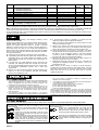
5.6 Dealing with Pagers
You may program the dialer to dial a pager's phone number and
send a numeric or verbal message. Communication with a single
pager requires two consecutive locations in the dialer memory one for the pager's phone number and another for the numeric
data sent to the pager. Since each dialer input has 4 memory
locations for phone numbers, each input can report to one pager
and 2 regular telephones or just two pagers.
3
If the pager's phone number is entered into Location No. 1, the
numeric message for that pager must be entered into the next
location (No. 2). If the pager's phone number is entered into
Location No. 2, the numeric message for that pager must be
entered into the next location (No. 3).
Important! Location No. 4 (the last location in the first group) and
No. 8 (the last location in the second group) can't be used for
pager phone numbers - in both cases there is no "next location"
with memory space for the message.
In the backup mode (see Para. 1.4H), it is advisable to use
Locations 1 & 2 or 5 & 6 for pager data and the remaining
locations for telephone numbers. The dialer will therefore call the
pager first and, since the pager doesn't acknowledge, at least
one of the telephone numbers will also be called.
Numeric pagers accept both the subscriber ID (PIN number) and
a numeric message which is registered and forwarded to the
subscriber. Voice pagers accept the subscriber ID (PIN number),
record a verbal message and relay it to the subscriber.
Note: Some pagers have a special phone number assigned to
each specific subscriber. This type of pager does not require a
PIN number.
Some pagers require an asterisk (∗) as a separator between the
subscriber code and the message. Other pagers require the
pound symbol (#). Correct programming is totally dependent on
your ability to make the dialer "talk" to the paging company's
computer in a language it "understands" (Fig. 5).
LOCATION NO. 3
(TEL. NUMBER)
ENTRIES INTO LOCATION 3 (LEFT TO RIGHT)
0 1 7 6 7 6 8 2 4 7 2 5 4
PAGER'S
AREA CODE
PAGER'S
TEL. NO.
Figure 6. Programming the Pager's 1st Location
F. Suppose the target pager requires a 5 second interval
between the end of dialing and the beginning of the message.
Also suppose that the PIN number is 9876 and the message
is 39051. Key the data as shown in Fig.7.
ENTRIES INTO LOCATION 4 (LEFT TO RIGHT)
4 0 5 9 8 7 6 1 3 9 0 5 1 1 4
PIN
NUMBER
DATA
DESIGNATOR
NUMERIC
MESSAGE
HEX "E" – DATA
DESIGNATOR
LETTER FOR PLAYING
THE RECORDED
VOICE MESSAGE
SEPARATION
CHARACTERS
( OR # - AS REQUIRED
BY THE PAGER)
RECORDED MESSAGE IS PLAYED ONCE ONLY
SHADED ENTRIES ARE INTERNAL COMMANDS
FOR THE DIALER USE ONLY
Figure 5. Typical Data Arrangement in Memory
Contact the paging company for specific interface details (PIN or
no PIN, separating characters required etc.).
Figure 5 depicts a typical arrangement of data in the dialer
memory for reporting an event to a pager. In this example, the
phone number is entered into memory location No. 3, and the
numeric message is entered into the memory location No. 4.
A hexadecimal E at the end of the phone number tells the dialer
move to the next memory location and send the data stored in it.
A hexadecimal E at the beginning of a memory location identifies
the contents of this location as pager data. A hexadecimal E after
the data serves as a cue for playing the voice message.
NUMERIC
MESSAGE
INTERVAL
(UP TO 99
SECONDS)
DATA LETTER (SWITCH
TO NEXT LOCATION)
E05 987 6– 390 51–E
DELAY
PIN
(SEC.) NUMBER
HEX "E" - DATA LETTER
(SWITCH TO THE
NEXT LOCATION)
PAGER'S
TEL. NO.
[∗][4] produces a Hexadecimal E, a cue for data in the next memory location.
0176768247 25E
TYPICAL
AREA CODE
LOCATION NO. 4
(NUMERIC MESSAGE)
To program communication with a pager:
A. Reserve 2 consecutive memory locations in the same group of four.
B. Suppose the first location you chose is No. 3. Select it by
keying [PROG], <3>, [#] .
C. Suppose the area code is 01767 and the telephone number is
682-4725. Key in the data as exemplified in Figure 6.
D. Press [#] to confirm the data just entered.
E. Select the next memory location by keying: [PROG], <4>, [#]
SEPARATOR
(IF REQUIRED)
– SEE NOTE
HEX "E" –
LETTER
FOR
PLAYING
THE
RECORDED
VOICE
Figure 7. Programming the Pager's 2nd Location
Notes: If the required separator is # - key [∗][1]
If the required separator is ∗ - key [∗][2].
In case of a pager that does not forward voice messages skip the last [∗][4].
If you need a 5-second delay anywhere within the
message, key [∗] [3].
G. Press [#] to confirm the data just entered.
5.7. Programming Summary
The dialer can be programmed equally well in the installer's office
or at the installation site. Follow the PROGRAMMING CHART
(Para. 5.8) row by row, and enter the appropriate variables. The
code options are explained in the second column, and the full
programming sequence for each variable is given in the fourth
column. Each programming step is enclosed in square brackets,
and may include more than one keystroke. The fifth column
shows the default values, and the last column (Prog) is left blank
for you to fill in your own programmed values.
Note: If no key is pressed for 30 seconds, programming will be
aborted and the selected location will revert to the previously
saved value.
To quit programming at any stage, press the [STOP] key.
5.8 Programming Chart
Loc. No.
Description of Parameters & Code Options
Entry Limits
Programming Format
1
2
3
4
5
6
7
8
9
10
1st telephone number associated with input Z-1
2nd telephone number associated with input Z-1
3rd telephone number associated with input Z-1
4th telephone number associated with input Z-1
1st telephone number associated with input Z-2
2nd telephone number associated with input Z-2
3rd telephone number associated with input Z-2
4th telephone number associated with input Z-2
Inaccessible to installers or users
Inhibit or permit the listen-in function:
0 - inhibited; 1 - permitted
Select Dialing method: 0 - DTMF; 1 - Pulse
No. of dialing attempts for alarms at input Z-1
No. of dialing attempts for alarms at input Z-2
Delay (in seconds) between trigger and action (to permit
the user to clear a false alarm)
20 digits
20 digits
20 digits
20 digits
20 digits
20 digits
20 digits
20 digits
–
0 or 1
[PR] [1] [#] [Num] [#]**
[PR] [2] [#] [Num] [#]**
[PR] [3] [#] [Num] [#]**
[PR] [4] [#] [Num] [#]**
[PR] [5] [#] [Num] [#]**
[PR] [6] [#] [Num] [#]**
[PR] 7] [#] [Num] [#]**
[PR] [8] [#] [Num] [#]**
Factory
Default
None
None
None
None
None
None
None
None
[PR] [10] [#] [Code] [#]
1
0 or 1
1 - 15*
1 - 15*
1 - 255*
[PR] [11] [#] [Code] [#]
[PR] [12] [#] [Num] [#]
[PR] [13] [#] [Num] [#]
[PR] [14] [#] [Sec] [#]
0
4
4
3
11
12
13
14
4
Prog.
Record
DE5817
Loc. No.
Description of Parameters & Code Options
Entry Limits
Programming Format
15
Order of transmission of message segments:
0 - alarm type segment first;
1 - identification segment first
LF output logic: 0 - N.C.; 1 - N.O.
Inaccessible to installers or users
Number of recorded message repeats
Listen-in duration (in seconds)
Z-1 input definition (Z-1 logic): 0 - N.O.; 1 - N.C.
Z-2 input definition (Z-2 logic): 0 - N.O.; 1 - N.C.
Selection of Backup or Non-backup reporting method:
0 - non-backup; 1 - backup (see note)
0 or 1
[PR] [15] [#] [Code] [#]
Factory
Default
1
0 or 1
[PR] [16] [#] [Num] [#]
1
–
1 - 255*
1 - 255*
0 or 1
0 or 1
0 or 1
[PR] [20] [#] [Num] [#]
[PR] [21] [#] [Sec] [#]
[PR] [22] [#] [Code] [#]
[PR] [23] [#] [Code] [#]
[PR] [24] [#] [Code] [#]
4
60
0
0
1
16
17-19
20
21
22
23
24
Prog.
Record
* The "00" value is illegal in this memory location
** When programming a 20-digit number, the LED will go off by itself after the 20th digit and the number will be saved.
Note: In the Backup reporting mode, receiving an acknowledge signal from a single telephone in a group of 4 is sufficient to consider the
current event closed and call off the communication session. The remaining 3 telephones are there for backup purposes only.
In the Non-Backup mode, an acknowledge signal must be received from each telephone in the group of 4 before the current event is
considered reported and closed.
6. TEST
After installation, programming, and message recording, correct
function should be verified.
Testing can be made easier if you possess a cellular telephone and a
portable AM/FM radio. For testing purposes, you can temporarily
program your cellular telephone's number in Location 1 (the first
telephone in the first group) and in Location 5 (the first telephone in
the second group). This way you can monitor both messages and
exercise remote control without bothering anyone. Switch the AM/FM
radio on to play softly and put it about 2m (6 ft) away from the dialer.
Then proceed as follows:
A. Trigger input Z-1 by opening or closing the circuit, as necessary.
B. If a predialing pause has not been programmed, the DIAL LED will
immediately light. It will remain lighted (tone dialing) or flash
(pulse dialing) indicating that the dialer has indeed begun its
dialing routine.
C. If all goes well, your cellular telephone will ring. Answer the call
and listen. The message should come through loud and clear.
Verify that the message segments are read in the correct order,
as programmed (identification segment first or alarm type
segment first).
D. Wait for the 3-second interval between message repetitions and
press the "1" key on your telephone. After that, the message
should not be repeated any more.
E. If the listening-in function is permitted, you should now start
hearing the radio through the telephone's earpiece.
Note: To prevent acoustic feedback, move into another room and
continue monitoring from there.
F. Watch for the warning beep that sounds shortly before end of
session. Press the "1" key on your telephone and verify that the
listen-in period carries on instead of coming to an abrupt end.
G. Press the telephone’s "9" key twice in succession. The dialer
should terminate the communication session and go "on hook". If
the dialer is in the non-backup mode (“0” has been selected
Location 24), press the STOP button ["DL-125C") or disconnect
the power ("DL-125CA") to prevent further dialing.
H. Reconnect the power (DL-125CA only) and trigger input Z-2 by
opening or closing the circuit, as necessary.
I. Repeat steps B through G above for this input too. If all goes well,
reprogram the telephone numbers in Locations 1 and 5 as
requested by the user.
Note: Testing can be carried out without a cellular telephone,
provided that you secure cooperation of the called parties. You must
warn them in advance that you are about to test the system, explain
briefly what they have to do and have them report to you later
whether all went well.
7. SPECIAL NOTES
FCC Requirements
1. The Federal Communications Commission (FCC) has established Rules
which permit this device to be directly connected to the telephone
network. Standardized jacks are used for these connections. This
equipment should not be used on party lines or coin lines.
2. If this device is malfunctioning, it may be causing also harm to the
telephone network; this device should be disconnected until the
source of the problem can be determined, and until repair has been
made. If this is not done, the telephone company may temporarily
disconnect service.
3. The telephone company may make changes in its technical
operations and procedures; if such changes affect the compatibility or
use of this device, the telephone company is required to give
adequate notice of the changes.
4 If the telephone company requests information on what equipment is
connected to their lines, inform them of:
(a) The telephone number that this unit is connected to,
(b) The ringer equivalence number (0.0B)
(c) The USOC jack required (RJ-31X), and
(d) The FCC registration number
Items (b) and (d) are indicated on the label. The ringer equivalence
number (REN) is used to determine how many devices can be connected
to your telephone line. In most areas, the sum of the RENs of all devices
on any one line should not exceed five (5.0). If too many devices are
attached, they may not ring properly.
APPENDIX A. USER INFORMATION
A.1 User Guidance
We recommend to photo-copy this section for all the dialer users - the proprietor of the protected premises and all called parties.
If programmed correctly, the dialer will operate automatically without While listening to the incoming verbal message, the called party can
user's intervention. However, the user can initiate an alarm or stop exercise some control over the dialer by sending DTMF (touchtone) codes
operation manually.
over the telephone line:
Pressing AL-1 will cause the dialer to call the first group
Serves as an acknowledgement. The dialer will stop
ALARM-1
1
sending the message and will permit "listening in".
AL-1 of phone numbers and send them the relevant verbal
message.
Before the listen-in period ends, the dialer beeps once.
Pressing [1] again will start another listen-in period.
Pressing AL-2 will cause the dialer to call the second
ALARM-2
AL-2 group of phone numbers and send them the relevant
verbal message.
Pressing STOP (DL-125C only) will cause the dialer to
Serves as an acknowledgement and causes the dialer to
STOP
9
9 stop sending the message and go "on hook". The dialer
STOP stop communicating, disengage the line and check both
inputs. If an input is "in alarm", a new communication
will then call the remaining numbers (if programmed to
session will start. If both inputs are "normal", the dialer
do so).
will standby. Note: This function is disabled in the DL125CA.
DE5817
5
A.2 Data Record
AL-1 DATA
AL-2 DATA
Message ............................................................................................
...........................................................................................................
1st called party ...................................................................................
2nd called party..................................................................................
3rd called party...................................................................................
4th called party...................................................................................
Message ............................................................................................
............................................................................................................
1st called party....................................................................................
2nd called party...................................................................................
3rd called party ...................................................................................
4th called party....................................................................................
WARRANTY
Visonic Limited (the “Manufacturer") warrants this product only (the "Product") to the original purchaser only (the
“Purchaser”) against defective workmanship and materials under normal use of the Product for a period of twelve
(12) months from the date of shipment by the Manufacturer.
This Warranty is absolutely conditional upon the Product having been properly installed, maintained and operated
under conditions of normal use in accordance with the Manufacturers recommended installation and operation
instructions. Products which have become defective for any other reason, according to the Manufacturers
discretion, such as improper installation, failure to follow recommended installation and operational instructions,
neglect, willful damage, misuse or vandalism, accidental damage, alteration or tampering, or repair by anyone
other than the manufacturer, are not covered by this Warranty.
The Manufacturer does not represent that this Product may not be compromised and/or circumvented or that the
Product will prevent any death and/or personal injury and/or damage to property resulting from burglary, robbery,
fire or otherwise, or that the Product will in all cases provide adequate warning or protection. The Product,
properly installed and maintained, only reduces the risk of such events without warning and it is not a guarantee
or insurance that such events will not occur.
THIS WARRANTY IS EXCLUSIVE AND EXPRESSLY IN LIEU OF ALL OTHER WARRANTIES,
OBLIGATIONS OR LIABILITIES, WHETHER WRITTEN, ORAL, EXPRESS OR IMPLIED, INCLUDING ANY
WARRANTY OF MERCHANTABILITY OR FITNESS FOR A PARTICULAR PURPOSE, OR OTHERWISE. IN
NO CASE SHALL THE MANUFACTURER BE LIABLE TO ANYONE FOR ANY CONSEQUENTIAL OR
INCIDENTAL DAMAGES FOR BREACH OF THIS WARRANTY OR ANY OTHER WARRANTIES
WHATSOEVER, AS AFORESAID.
THE MANUFACTURER SHALL IN NO EVENT BE LIABLE FOR ANY SPECIAL, INDIRECT, INCIDENTAL,
CONSEQUENTIAL OR PUNITIVE DAMAGES OR FOR LOSS, DAMAGE, OR EXPENSE, INCLUDING LOSS
OF USE, PROFITS, REVENUE, OR GOODWILL, DIRECTLY OR INDIRECTLY ARISING FROM
PURCHASER’S USE OR INABILITY TO USE THE PRODUCT, OR FOR LOSS OR DESTRUCTION OF
OTHER PROPERTY OR FROM ANY OTHER CAUSE, EVEN IF MANUFACTURER HAS BEEN ADVISED OF
THE POSSIBILITY OF SUCH DAMAGE.
THE MANUFACTURER SHALL HAVE NO LIABILITY FOR ANY DEATH, PERSONAL AND/OR BODILY
INJURY AND/OR DAMAGE TO PROPERTY OR OTHER LOSS WHETHER DIRECT, INDIRECT, INCIDENTAL,
CONSEQUENTIAL OR OTHERWISE, BASED ON A CLAIM THAT THE PRODUCT FAILED TO FUNCTION.
However, if the Manufacturer is held liable, whether directly or indirectly, for any loss or damage arising under this
limited warranty, THE MANUFACTURER'S MAXIMUM LIABILITY (IF ANY) SHALL NOT IN ANY CASE
EXCEED THE PURCHASE PRICE OF THE PRODUCT, which shall be fixed as liquidated damages and not as a
penalty, and shall be the complete and exclusive remedy against the Manufacturer.
When accepting the delivery of the Product, the Purchaser agrees to the said conditions of sale and warranty and
he recognizes having been informed of.
Some jurisdictions do not allow the exclusion or limitation of incidental or consequential damages, so these
limitations may not apply under certain circumstances.
The Manufacturer shall be under no liability whatsoever arising out of the corruption and/or malfunctioning of any
telecommunication or electronic equipment or any programs.
The Manufacturers obligations under this Warranty are limited solely to repair and/or replace at the
Manufacturer’s discretion any Product or part thereof that may prove defective. Any repair and/or replacement
shall not extend the original Warranty period. The Manufacturer shall not be responsible for dismantling and/or
reinstallation costs. To exercise this Warranty the Product must be returned to the Manufacturer freight pre-paid
and insured. All freight and insurance costs are the responsibility of the Purchaser and are not included in this
Warranty.
This warranty shall not be modified, varied or extended, and the Manufacturer does not authorize any person to
act on its behalf in the modification, variation or extension of this warranty. This warranty shall apply to the
Product only. All products, accessories or attachments of others used in conjunction with the Product, including
batteries, shall be covered solely by their own warranty, if any. The Manufacturer shall not be liable for any
damage or loss whatsoever, whether directly, indirectly, incidentally, consequentially or otherwise, caused by the
malfunction of the Product due to products, accessories, or attachments of others, including batteries, used in
conjunction with the Products. This Warranty is exclusive to the original Purchaser and is not assignable.
This Warranty is in addition to and does not affect your legal rights. Any provision in this warranty which is
contrary to the Law in the state or country were the Product is supplied shall not apply.
Warning: The user must follow the Manufacturer’s installation and operational instructions including testing the
Product and its whole system at least once a week and to take all necessary precautions for his/her safety and
the protection of his/her property.
1/08
W.E.E.E. Product Recycling Declaration
For information regarding the recycling of this product you must contact the company from which you orignially purchased it. If you are discarding this product and not
returning it for repair then you must ensure that it is returned as identified by your supplier. This product is not to be thrown away with everyday waste.
Directive 2002/96/EC Waste Electrical and Electronic Equipment.
VISONIC LTD . (ISRAEL):
VISONIC INC. (U.S.A.):
VISONIC LTD. (UK):
INTERNET:
VISONIC LTD. 2008
6
P.O.B 22020 TEL-AVIV 61220 ISRAEL. PHONE: (972-3) 645-6789, FAX: (972-3) 645-6788
65 WEST DUDLEY TOWN ROAD, BLOOMFIELD CT. 06002-1376. PHONE: (860) 243-0833, (800) 223-0020 FAX: (860) 242-8094
7 COPPERHOUSE COURT, CALDECOTTE, MILTON KEYNES. MK7 8NL. PHONE: (0870) 7300800 FAX: (0870) 7300801
www.visonic.com
DL-125C, DL-125CA
DE5817- (REV. 3, 8/08)
DE5817