1
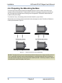
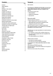
ACS and ACS LP Series
Rotary Stages User’s Manual
P/N: EDS103 (Revision 1.03.00)
Dedicated to the Science of Motion
Aerotech, Inc.
101 Zeta Drive,
Pittsburgh, PA, 15238
Phone: 412-963-7470
Fax: 412-963-7459
www.aerotech.com
Product Registration
Register online at: http://www.aerotech.com/prodreg.cfm
Technical Support
United States Headquarters:
Phone: (412) 967-6440
Fax: (412) 967-6870
Email: [email protected]
United Kingdom:
Phone: +44 118 940 9400
Fax: +44 118 940 9401
Email: [email protected]
Germany:
Phone: +49 911 967 9370
Fax: +49 911 967 93720
Email: [email protected]
Japan:
Phone: +81(0)47-489-1741 (Sales)
Phone: +81(0)47-489-1742 (Service)
Fax: +81(0)47-489-1743
Email: [email protected]
China:
Phone: +852-3793-3488
Email: [email protected]
Revision History
Revision 1.03.00
April 5, 2011
Revision 1.02.00
August 10, 2010
Revision 1.01.00
February 16, 2010
Revision 1.00.00
February 10, 2006
Product names mentioned herein are used for identification purposes only and may be trademarks of
their respective companies.
© Aerotech, Inc. 2011
ACS and ACS LP Stages User's Manual
Table of Contents
Table of Contents
Table of Contents
List of Figures
List of Tables
iii
v
vii
Chapter 1: Overview
1
1.1. Standard Features
1.1.1. ACS Optional Features
1.1.2. Model Numbers
1.2. Dimensions
1.3. Safety Procedures and Warnings
1.4. EC Declaration of Incorporation
Chapter 2: Installation
2.1. Unpacking and Handling the Stage
2.2. Preparing the Mounting Surface
2.3. Securing the Stage to the Mounting Surface
2.4. Attaching the Payload to the Stage
2.5. Electrical Installation
2.6. Air Requirements
Chapter 3: Operating Specifications
3.1. Environmental Specifications
3.2. ACS Basic Specifications
3.3. ACS LP Basic Specifications
3.4. Limit Switch Wiring
3.5. Standard Motor Wiring
3.6. Vacuum Operation
Chapter 4: Maintenance
4.1. Service and Inspection Schedule
4.2. Cleaning and Lubrication
4.2.1. Collet and Collet Chuck Lubrication and Cleaning
4.3. Seal Replacement
4.3.1. Piston Seal Change Procedure
4.3.2. Ringseal O-ring Replacement (ACS Only)
4.3.3. Rotary Union Seals for Three-Jaw Gripper Stages (ACS Only)
4.3.4. Water Jacket Seal Replacement (ACS Only)
4.4. Changing ACS and ACS LP Workholding Devices
4.4.1. Availible Workholding Devices
4.4.2. Collet Change Procedure
4.4.3. Changing Collet Chucks (ACS Only)
4.4.4. Gripper Configurations (ACS Only)
2
3
4
7
13
15
17
17
18
19
21
21
22
23
23
24
29
31
32
36
37
37
37
38
39
39
42
44
46
48
48
48
50
52
Appendix A: Warranty and Field Service
55
Appendix B: Technical Changes
57
Index
59
Reader's Comments
61
www.aerotech.com
iii
Table of Contents
iv
ACS and ACS LP Stages User's Manual
www.aerotech.com
ACS and ACS LP Stages User's Manual
List Of Figures
List of Figures
Figure 1-1:
Figure 1-2:
Figure 1-3:
Figure 1-4:
Figure 1-5:
Figure 1-6:
Figure 1-7:
Figure 1-8:
Figure 2-1:
Figure 2-2:
Figure 2-3:
Figure 3-1:
Figure 3-2:
Figure 3-3:
Figure 4-1:
Figure 4-2:
Figure 4-3:
Figure 4-4:
Figure 4-5:
Figure 4-6:
Figure 4-7:
Figure 4-8:
Figure 4-9:
Figure 4-10:
Figure 4-11:
Figure 4-12:
Figure 4-13:
Figure 4-14:
Figure 4-15:
Figure 4-16:
ACS-150 Rotary Stage with ER Collet and Three-Jaw Gripper
ACS-100 Dimensions
ACS-150-ER Dimensions
ACS-150-3J Dimensions
ACS-200-3J Dimensions
ACS-100LP Dimensions
ACS-150LP Dimensions
ACS-200LP Dimensions
Results of Flat Versus Non-Flat Mounting
Front view of a Typical ACS-150 Stage Showing End Mounting Holes
Typical ACS-150 Stage Showing Side Mounting Holes and T-Slot Detail
Standard Wiring Connectors for ACS-150/200 and ACS-150LP/200LP Stages
Standard Wiring Connectors for ACS-100 and ACS-100LP Stages
Optional Wiring Connectors for ACS-100 Stages
Exploded View of Collet Assembly
Piston Seal Installation Procedure
Cross-section View of Piston Showing Seal Orientation
Typical Ringseal with O-ring Installed
Ringseal Removal Tool Dimensions
Cross-section View of Ringseal Showing Both O-rings
Exploded Drawing of Rear Seal Components
Cross-section View of Rear Seal Showing Seal Orientations
Exploded View of Water Jacket Housing Assembly
Cross-section View of Water Jacket Seal Showing Seal Orientation
Schematic of Collet Insertion Into and Removal from Collet Nut
Installation Procedure for Collet
Exploded View of Collet Assembly
Gripper Mounting Hole Locations in ACS and ACS LP Shaft
Mounting Holes for Three-Jaw Gripper
Air Inlets in Three-Jaw Grippers
www.aerotech.com
3
7
8
9
10
11
11
12
18
19
20
32
33
34
39
41
41
42
43
43
44
45
46
47
49
49
50
52
53
53
v
List of Figures
vi
ACS and ACS LP Stages User's Manual
www.aerotech.com
ACS and ACS LP Stages User's Manual
List of Tables
List of Tables
Table 1-1:
Table 1-2:
Table 3-1:
Table 3-2:
Table 3-3:
Table 3-4:
Table 3-5:
Table 3-6:
Table 3-7:
Table 3-8:
Table 3-9:
Table 3-10:
Table B-1:
Table B-2:
ACS Model Numbering System
ACS LP Model Numbering System
Environmental Specifications
ACS-100 Series Specifications
ACS-150 Series Specifications
ACS-200 Series Specifications
ACS Series Resolution Information
ACS Motor Specifications
ACS LP Series Specifications
ACS LP Maximum Encoder Frequency
ACS LP Motor Specifications
Motor Wiring Pinout Descriptions
Current Changes (1.03.00)
Archived Changes
www.aerotech.com
4
6
23
24
25
26
27
28
29
30
30
35
57
58
vii
List of Tables
viii
ACS and ACS LP Stages User's Manual
www.aerotech.com
ACS and ACS LP Stages User's Manual
Overview
Chapter 1: Overview
Aerotech’s ACS and ACS LP series rotary stages with integrated ER collet chuck or 3-jaw gripper configuration provide automated material handling capability for a wide range of materials and applications.
This manual describes Aerotech’s ACS and ACS LP series direct drive rotary positioning stages.
This chapter introduces standard and optional features of the ACS and ACS LPstages, explains the model
numbering system, and gives general safety precautions.
www.aerotech.com
Chapter 1
1
Overview
ACS and ACS LP Stages User's Manual
1.1. Standard Features
All ACS and ACS LP stages come standard with a direct drive brushless motor. An integral non-contact
rotary union is standard on the ACS-100, ACS-100LP, ACS-150, and ACS-150LP stages. These features
combine to create a low friction, low maintenance rotary stage capable of high accelerations and low positioning error. With a non-contact rotary union, there are no seals to be replaced or lubricated allowing for a lifetime of maintenance free performance. The brushless, slotless motor design is useful for applications
requiring good velocity control, as it allows for smooth rotation without the presence of a torque ripple. There
are no brushes to wear, no belts to tension, and no gears to wear resulting in a completely maintenance-free
motor.
All ACS LP stages come standard with ER collet chucking.
2
Chapter 1
www.aerotech.com
ACS and ACS LP Stages User's Manual
Overview
1.1.1. ACS Optional Features
The ACS series stages can be equipped with an integrated ER collet chuck or a three-jaw gripper chuck. See
Table 1-1 for more information regarding available options for each stage.
Both the ACS-100 and ACS-150 have available ER collet chucks. Collets are available from machine-tool
component suppliers in sizes that support tube diameters from 0.5 mm to 30 mm. The collet is retained with a
threaded collet nut enabling quick-changeover. It is configured in a “fail-safe” normally-closed mode where full
clamping force is applied when no air pressure is present. The ACS-100 accepts an ER8 collet capable of
holding tube diameters from 0.5 mm to 5.0 mm. The ACS-150 can be configured to accept either ER25 or
ER40 series collets. Aerotech recommends using an ER25 collet for holding requirements of 1 mm to 16 mm
and using an ER40 collet for holding requirements of 15.5 mm to 30 mm. The ER25 also has an optional
sealed “water-jacket” configuration that can be used for fluid delivery in wet laser cutting applications.
N O T E : While the ER40 collet can support tubes up to 30 mm in diameter, tubes greater than 24.5 mm in
diameter cannot extend more than 70 mm below the top of the collet.
Both the ACS-150 and ACS-200 support three-jaw grippers with clear apertures for product feed-through. All
gripper assemblies are configurable as either normally-open or normally-closed with various jaw strokes to
support a wide range of material sizes. The gripper can be fitted with custom jaws for the handling of materials with non-round profiles such as square or hexagonal bar stock. The normally-open and normally-closed
options also provide the ability to grip either the O.D. or I.D. of the material.
Figure 1-1:
www.aerotech.com
ACS-150 Rotary Stage with ER Collet and Three-Jaw Gripper
Chapter 1
3
Overview
ACS and ACS LP Stages User's Manual
1.1.2. Model Numbers
The stage model number indicates the optional features on a particular stage. To determine the options on
your stage, refer to Table 1-1 for an explanation of the ACS numbering system and Table 1-2 for an explanation of the ACS LP numbering system.
Example: ACS-150-115-3J-12-AS-NC-10-NS
This designates an ACS and ACS LP-150 stage with 150 mm direct drive motor, 1 Vpp amplified sine position transducer, normally closed 10 mm stroke three-jaw gripper, and no rear seal.
The table below lists the available options in the order they appear in the example above. Aerotech continually improves its product offerings, and listed options may be superseded at any time. Refer to the most
recent edition of the Aerotech Motion Control Product Guide for the most current product information at
www.aerotech.com.
Table 1-1:
ACS Model Numbering System
ACS Series Direct Drive Rotary Stage
ACS
Direct-drive rotary stage with integral pneumatic collet chuck or 3-jaw gripper and rotary union.
Frame Size
-100-85
100 mm diameter direct drive rotary stage with 0.4 N-m continuous torque and integral rotary
union
-100-135
100 mm diameter direct drive rotary stage with 1.9 N-m continuous torque and integral rotary
union
-150-115
150 mm diameter direct drive rotary stage with 3.6 N-m continuous torque and integral rotary
union
-150-135
150 mm diameter direct drive rotary stage with 6.5 N-m continuous torque and integral rotary
union
-150-185
150 mm diameter direct drive rotary stage with 11.4 N-m continuous torque and integral rotary
union
-200-155
200 mm diameter direct drive rotary stage with 16.9 N-m continuous torque and integral rotary
union
-200-285
200 mm diameter direct drive rotary stage with 24.9 N-m continuous torque and integral rotary
union
Fixture Type
4
-ER8
Air-actuated ER8 collet holder, normally closed, supports tube diameters from 0.5 mm to 5 mm;
only available on ACS-100-XXX
-ER25
Air-actuated ER25 collet holder, normally closed, supports tube diameters from 1 mm to 16 mm;
only available on ACS-150-XXX
-ER40
Air-actuated ER40 collet holder, normally closed, supports tube diameters from 15.5 mm to 30
mm; only available on ACS-150-XXX
-3J-12
Air-actuated 3-jaw gripper with 12 mm clear aperture, ±20 micron repeatability; available on
ACS-150 and ACS-200
-3J-25
Air-actuated 3-jaw gripper with 25 mm clear aperture, ±20 micron repeatability; only available
on ACS-200
Chapter 1
www.aerotech.com
ACS and ACS LP Stages User's Manual
Overview
Table 1-1: Model Numbering System (continued)
Position Transducer (1)
-AS
1 Vpp sine wave output; 360 arc-sec resolution on ACS-150 and 240 arc-sec resolution on
ACS-200
-X5
Square wave digital output; 18 arc-sec resolution on ACS-150 and 12 arc-sec resolution on
ACS-200
-X10
Square wave digital output; 9 arc-sec resolution on ACS-150 and 6 arc-sec resolution on ACS200
-X25
Square wave digital output; 3.6 arc-sec resolution on ACS-150 and 2.4 arc-sec resolution on
ACS-200
-X50
Square wave digital output; 1.8 arc-sec resolution on ACS-150 and 1.2 arc-sec resolution on
ACS-200
Gripper Options(2)
-NC-10
Normally closed 3J-12 gripper with 10 mm jaw stroke, 240 N (52 lb) peak grip force
-NO-10
Normally open 3J-12 gripper with 10 mm jaw stroke, 240 N (52 lb) peak grip force
-NC-13
Normally closed 3J-25 gripper with 13 mm jaw stroke, 450 N (102 lb) peak grip force
-NO-13
Normally open 3J-25 gripper with 13 mm jaw stroke, 450 N (102 lb) peak grip force
-NC-16
Normally closed 3J-12 gripper with 16 mm jaw stroke, 150 N (33 lb) peak grip force
-NO-16
Normally open 3J-12 gripper with 16 mm jaw stroke, 150 N (33 lb) peak grip force
-NC-20
Normally closed 3J-25 gripper with 20 mm jaw stroke, 270 N (60 lb) peak grip force
-NO-20
Normally open 3J-25 gripper with 20 mm jaw stroke, 270 N (60 lb) peak grip force
ER Collet Seal Options
-NS
No rear seal (standard)
-S
Rear shaft seal
-W
Water jacket assembly for wet cutting applications; seal diameter specified with Water Jacket
Seal option; only available with ER25 collet configuration.
ER Collet Size
-XX-YYMM
Electro-polished DIN6499AA ER style collet; supports tube diameters from XX to YY mm
Water Jacket Seal
-X.XXMM
Water jacket seal assembly for nominal tube diameter X.XX mm; consult factory for available
sizes
Tooling
-WRENCH
Spanner wrench set for changing ER collet
Air Purge
-AP
Air purge fitting to positive pressurize ACS stage to limit ingress of airborne particulates
Connector options for ACS-100
-HPD
4 pin D-style motor power and 25 pin D-style feedback
-25D
25 pin D-style motor power and 25 pin D-style feedback
(1) Digital output encoder signals are synthesized with a 16 MHz clock. Care must be taken to ensure that the encoder sample rate on
the controller is at least 16 MHz or higher. Slower clock rates are available on request.
(2) Available only with 3-jaw gripper option.
www.aerotech.com
Chapter 1
5
Overview
Table 1-2:
ACS and ACS LP Stages User's Manual
ACS LP Model Numbering System
ACS LP Series Direct Drive Rotary Stage
ACS
Direct-drive rotary stage with integral pneumatic collet chuck Frame Size and Fixture Type
Frame Size and Fixture Type
-100LP
100 mm wide direct-drive rotary stage with 1.8 N-m peak torque output and integral rotary
union, air-actuated ER8 (1) collet holder, normally closed, supports tube diameters from 0.7
mm to 5 mm
-150LP
150 mm wide direct-drive rotary stage with 11.7 N-m peak torque output and integral rotary
union, air-actuated ER25 (1) collet holder, normally closed, supports tube diameters from 1
mm to 16 mm
-200LP
200 mm wide direct-drive rotary stage with 30 N-m peak torque output and integral rotary
union, air-actuated ER40 (1) collet holder, normally closed, supports tube diameters from 16
mm to 30 mm. Tubes with a diameter greater than 24.5 mm cannot extend more than 70 mm
below the top of the collet.
Winding Options
-A
Standard motor winding
-B
Optional motor winding (consult Aerotech for availability)
Position Transducer
-AS
Standard feedback device; 1 Vpp sine wave output; 360 arc-sec resolution on ACS-100LP
and 240 arc-sec on ACS-150/200LP
-X5(2)
Square wave digital output; 18 arc-sec resolution on ACS-100LP and 6 arc-sec resolution
on ACS-150/200LP
-X10(2)
Square wave digital output; 9 arc-sec resolution on ACS-100LP and 3 arc-sec resolution on
ACS-150/200LP
-X25(2)
Square wave digital output; 3.6 arc-sec resolution on ACS-100LP and 2.4 arc-sec resolution
on ACS-150/200LP
-X50(2)
Square wave digital output; 1.8 arc-sec resolution on ACS-100LP and 1.2 arc-sec resolution
on ACS-150/200LP
Construction Options
-WRENCH SET
Spanner wrench for changing ER collets
-XMM
DIN6499 AA collet. Consult factory for available sizes
(1) Collet holder requires dry (0°C dewpoint), oil-less, filtered air (0.25 micron) or 99.99% pure filtered nitrogen (0.25 micron).
(2) Requires a controller with a 16 MHz encoder sample rate.
6
Chapter 1
www.aerotech.com
ACS and ACS LP Stages User's Manual
Overview
1.2. Dimensions
Figure 1-2:
www.aerotech.com
ACS-100 Dimensions
Chapter 1
7
Overview
ACS and ACS LP Stages User's Manual
Figure 1-3:
8
ACS-150-ER Dimensions
Chapter 1
www.aerotech.com
ACS and ACS LP Stages User's Manual
Figure 1-4:
www.aerotech.com
Overview
ACS-150-3J Dimensions
Chapter 1
9
Overview
ACS and ACS LP Stages User's Manual
Figure 1-5:
10
ACS-200-3J Dimensions
Chapter 1
www.aerotech.com
ACS and ACS LP Stages User's Manual
www.aerotech.com
Figure 1-6:
ACS-100LP Dimensions
Figure 1-7:
ACS-150LP Dimensions
Chapter 1
Overview
11
Overview
ACS and ACS LP Stages User's Manual
Figure 1-8:
12
ACS-200LP Dimensions
Chapter 1
www.aerotech.com
ACS and ACS LP Stages User's Manual
Overview
1.3. Safety Procedures and Warnings
The following statements apply throughout this manual. Failure to observe these precautions could result in
serious injury to those performing the procedures and damage to the equipment.
This manual and any additional instructions included with the stage should be retained for the lifetime of the
stage.
To minimize the possibility of electrical shock and bodily injury or death, disconnect all electrical power prior to making any electrical connections.
To minimize the possibility of electrical shock and bodily injury or death when any electrical
circuit is in use, ensure that no person comes in contact with the circuitry when the stage is
connected to a power source.
To minimize the possibility of bodily injury or death, disconnect all electrical power prior to
making any mechanical adjustments.
Moving parts of the stage can cause crushing or shearing injuries. All personnel must
remain clear of any moving parts.
Improper use of the stage can cause damage, shock, injury, or death. Read and understand
this manual before operating the stage.
If the stage is used in a manner not specified by the manufacturer, the protection provided
by the stage can be impaired.
Stage cables can pose a tripping hazard. Securely mount and position all stage cables to
avoid potential hazards.
www.aerotech.com
Chapter 1
13
Overview
ACS and ACS LP Stages User's Manual
Do not expose the stage to environments or conditions outside the specified range of operating environments. Operation in conditions other than those specified can cause damage to
the equipment.
The stage must be mounted securely. Improper mounting can result in injury and damage to
the equipment.
Use care when moving the stage. Manually lifting or transporting stages can result in injury.
Only trained personnel should operate, inspect, and maintain the stage.
This stage is intended for light industrial manufacturing or laboratory use. Use of the stage
for unintended applications can result in injury and damage to the equipment.
Before using this stage, perform an operator risk assessment to determine the needed
safety requirements.
14
Chapter 1
www.aerotech.com
ACS and ACS LP Stages User's Manual
Overview
1.4. EC Declaration of Incorporation
Manufactorer:
Aerotech, Inc.
101 Zeta Drive
Pittsburgh, PA 15238
USA
herewith declares that the product:
Aerotech, Inc. ACS and ACS LP Stage
is intended to be incorporated into machinery to constitute machinery covered by the Directive
2006/42/EC as amended;
does therefore not in every respect comply with the provisions of this directive;
and that the following harmonized European standards have been applied:
EN ISO 12100-1,-2:2003+A1:2009
Safety of machinery - Basic concepts, general principles for design
ISO 14121-1:2007
Safety of machinery - Risk assessment - Par 1: Principles
EN 60204-1:2005
Safety of machinery - Electrical equipment of machines - Part 1: General requirements
and further more declares that
it is not allowed to put the equipment into service until the machinery into which it
is to be incorporated or of which it is to be a component has been found and
declared to be in conformity with the provisions of the Directive 2006/42/EC and
with national implementing legislation, i.e. as a whole, including the equipment
referred to in this Declaration.
Authorized Representative:
Address:
Manfred Besold
AEROTECH GmbH
Süd-West-Park 90
D-90449 Nürnberg
Name:
Position:
Location:
Date:
www.aerotech.com
Alex Weibel /
Engineer Verifying Compliance
Pittsburgh, PA
April 5, 2011
Chapter 1
15
Overview
16
ACS and ACS LP Stages User's Manual
Chapter 1
www.aerotech.com
ACS and ACS LP Stages User's Manual
Installation
Chapter 2: Installation
This chapter describes the installation procedure for the ACS and ACS LP stages, including handling the
stage properly, preparing the mounting surface to accept the stage, securing the stage to the mounting surface, attaching the payload, and making the electrical connections.
Installation must follow the instructions in this chapter. Failure to follow these instruction
could result in injury and damage to the equipment.
2.1. Unpacking and Handling the Stage
Carefully remove the stage from the protective shipping container. Use compressed nitrogen or clean, dry air
to remove any dust or debris that has collected during shipping.
Before operating the stage, it is important to let the stage stabilize at room temperature for at least 12 hours.
This soak-out time is required because of thermal expansion and contraction of the parts used to build the
stage. Allowing the stage to stabilize at room temperature will ensure that all of the alignments, preloads, and
tolerances are the same as they were when tested at Aerotech. Set the stage on a smooth, flat, and clean surface.
Each stage has a label listing the system part number and serial number. These numbers contain information
necessary for maintaining or updating system hardware and software. Locate this label and record the information for later reference. If any damage has occurred during shipping, report it immediately.
Improper stage handling could adversely affect the stage’s performance. Use care when
moving the stage. Manually lifting or transporting stages can cause injury.
Lift the stage only by the base.
Do not use the ballscrew or motor as lifting points.
www.aerotech.com
Chapter 2
17
Installation
ACS and ACS LP Stages User's Manual
2.2. Preparing the Mounting Surface
The mounting surface should be flat and have adequate stiffness in order to achieve the maximum performance from the ACS and ACS LP. When an ACS or ACS LP series stage is mounted to a non-flat surface, the stage can be distorted as the mounting screws are tightened. This distortion will decrease the
overall accuracy of the stage.
To maintain accuracy, the mounting surface should be flat within 1 µm per 25 mm.
Adjustments to the mounting surface must be done before the stage is secured. The effects of flatness on
mounting are illustrated in Figure 2-1.
Figure 2-1:
Results of Flat Versus Non-Flat Mounting
N O T E : The stage base is precision machined and verified for flatness prior to stage assembly at the factory. If machining is required to achieve the desired flatness, it should be performed on the mounting surface rather than the stage base. Shimming should be avoided if possible. If shimming is required, it should
be minimized to improve the rigidity of the system.
18
Chapter 2
www.aerotech.com
ACS and ACS LP Stages User's Manual
Installation
2.3. Securing the Stage to the Mounting Surface
ACS and ACS LP series stages have numerous mounting holes available to secure the stage to the mounting
surface. Figure 2-2 shows the mounting holes at the rear of the stage. On ACS-150, ACS-150LP, ACS-200
and ACS-200LP stages, these are 7 mm diameter holes designed for either 6 mm or ¼ inch socket head cap
screws. The sides of the stage are equipped with several M6 x 1.0 tapped holes. Eight T-slots are included as
a standard feature on the ACS-150, ACS-150LP, ACS-200 and ACS-200LP models. The dimensions of
these T-slots are identical for ACS-150, ACS-150LP, ACS-200 and ACS-200LP stages and are detailed in
Figure 2-3.
On ACS-100 and ACS-100 LP stages, the rear mounting holes are designed for either a 5 mm or #10 socket
head cap screw, and the side holes are tapped M5 x 0.8 x 5 mm deep. T-slots are not available on the ACS100 and ACS-100 LP series stages.
Figure 2-2 and Figure 2-3 show ACS stages. On ACS LP stages, the mounting holes are located in equivalent
places.
The stage must be mounted securely. Improper mounting can result in injury and damage to
the equipment.
Figure 2-2:
www.aerotech.com
Front view of a Typical ACS-150 Stage Showing End Mounting Holes
Chapter 2
19
Installation
Figure 2-3:
20
ACS and ACS LP Stages User's Manual
Typical ACS-150 Stage Showing Side Mounting Holes and T-Slot Detail
Chapter 2
www.aerotech.com
ACS and ACS LP Stages User's Manual
Installation
2.4. Attaching the Payload to the Stage
To prevent damage to the stage or parts, test the operation of the stage before any material is held in the collet or gripper. Proceed with the electrical installation and test the motion control system in accordance with
the system documentation. Document all results for future reference. For information on electrical connections, refer to the documentation of the motion control system or the wiring drawings in Chapter 3: Operating Specifications.
To operate the collet, clean compressed air or nitrogen must be supplied to the stage. The one-touch air inlet
fitting accepts ¼ inch OD plastic airline. Simply push the airline into the fitting and supply air to the stage.
Aerotech can provide valves, fittings, and airlines to create a custom collet system. Contact the factory for
more details.
Once air is supplied, material of the appropriate size can be placed in the collet. All collets supplied by Aerotech are clearly labeled with their clamping size range and collet style. Be sure to use only the correct size
material in the collet. The accuracy of the collet could be compromised if the incorrect material size is
clamped. Never clamp material or tools that are larger than the specified range. It is also important to have
the material or tool inserted at least 2/3 the length of the collet bore. Any less than this could cause permanent deformation of the collet and reduce accuracy.
2.5. Electrical Installation
Aerotech motion control systems are adjusted at the factory for optimum performance. When the ACS or
ACS LP series stage is part of a complete Aerotech motion control system, setup involves connecting the
stage to the appropriate drive chassis with the cables provided. Connect the provided cables to the feedback
and motor connectors on the stage. Labels on the drive indicate the appropriate connections. Refer to the
appropriate drive manuals and documentation for additional installation and operation information. In some
cases, if the system is uniquely configured, a drawing showing system interconnects is supplied.
See Section 3.5. for more information on the electrical connections on the ACS and ACS LP stages.
Never connect or disconnect any electrical component or connecting cable while power is
applied, or serious damage may result.
If you are using cables other than those provided by Aerotech, you must connect the pin in
the motor connector carrying the stage's protective ground (shown in Section 3.5. ) to a
ground connection.
www.aerotech.com
Chapter 2
21
Installation
ACS and ACS LP Stages User's Manual
2.6. Air Requirements
The air pressure supplied to the collet holder or gripper is important in ensuring that the material or tool is
released properly, or for the optional normally-open (NO) gripper (ACS only), that the material is held
securely. If compressed air is used, it must be filtered to 0.25 microns, dry to 0º F dew point, and oil free. If
nitrogen is used, it must be 99.99 percent pure and filtered to 0.25 microns. For stages equipped with a threejaw gripper, air must be regulated to between 3 and 7 bar (45 and 100 psig). Higher pressures could cause
damage to the gripper assembly and should be avoided. For stages equipped with an ER collet chuck, the
chuck becomes fully open at approximately 4-7 bar (60-100 psig) depending on the collet size. Higher pressures will not cause damage to the rotary union, but high flow rates will result. Because of the noncontact
rotary union design on collet-equipped stages, a small amount of leakage will occur. Approximate leakage
rates of between 10 Lpm (0.5 CFM) and 40 Lpm (1.4 CFM), depending on pressure, will be observed when
the collet is open.
22
Chapter 2
www.aerotech.com
ACS and ACS LP Stages User's Manual
Operating Specifications
Chapter 3: Operating Specifications
This chapter contains general technical information about ACS and ACS LP series stages. Included are
basic product specifications, load capacities and ratings, and motor wiring diagrams.
3.1. Environmental Specifications
The environmental specifications for the ACS and ACS LP are listed in the following table.
Table 3-1:
Environmental Specifications
Ambient
Temperature
Operating: 10° to 35° C (50° to 95° F)
The optimal operating temperature is 20° C ±2° C (68° F ±4° F). If at any time the operating temperature deviates from 20° C degradation in performance could occur. Contact Aerotech for
information regarding your specific application and environment.
Storage: 0° to 40° C (32° to 104° F) in original shipping packaging
Humidity
Operating: 40 percent to 60 percent RH
The optimal operating humidity is 50 percent RH.
Storage: 30 percent to 60 percent RH, non-condensing in original packaging
Altitude
Operating: 0 to 2,000 m (0 to 6,562 ft) above sea level
Contact Aerotech if your specific application involves use above 2,000 m or below sea level.
Vibration
Use the system in a low vibration environment. Excessive floor or acoustical vibration can affect
stage and system performance. Contact Aerotech for information regarding your specific application.
Dust Exposure
The ACS and ACS LP stages are not suited for dusty or wet environments. This equates to an
ingress protection rating of IP00.
Use
Indoor use only
Do not expose the stage to environments or conditions outside the specified range of operating environments. Operation in conditions other than those specified can cause damage to
the equipment.
www.aerotech.com
Chapter 3
23
Operating Specifications
ACS and ACS LP Stages User's Manual
3.2. ACS Basic Specifications
ACS series rotary stage specifications are shown in Table 3-2, Table 3-3, and Table 3-4. Encoder resolution
information is given in Table 3-5. Motor specifications are given in Table 3-6.
Table 3-2:
ACS-100 Series Specifications
ACS Series
Total Travel
ACS-100-85
Gripper/Collet Option
Three-Jaw Grippler Travel
ER8
3J-12
NA
3J-25
Torque Output
Continuous Current, Stall
ACS-100-135
±360° Continuous
NA
Peak
1.8 Nm
7.84 Nm
Continuous
0.4 Nm
1.96 Nm
Apk
2
3.7
Arms
1.43
2.6
Accuracy
±72.7 µrad (±15 arc sec)
Repeatability
±29 µrad (±6 arc sec)
Axial Runout
±15 µrad
Radial Runout
±15 µrad
Wobble
Aperture
±48.5 µrad (±10 arc sec)
ER8
5 mm
ER25
ER25, ER40, 3J-12, and 3J-25 are not applicable
ER40
NA
3J-12
NA
3J-25
NA
Resolution
0.87-87.3 µrad (0.18-18 arc sec)
Moment Load
30 Nm
Axial Load
10 kg
Rated Speed
Motor Type
24
800 rpm
S-76-35-A
Chapter 3
S-76-85-A
www.aerotech.com
ACS and ACS LP Stages User's Manual
Table 3-3:
Operating Specifications
ACS-150 Series Specifications
ACS Series
Total Travel
ACS-150-115
Gripper/Collet Option
Three-Jaw Grippler Travel
Continuous Current, Stall
10 mm, 16 mm
NA
Peak
14.4 Nm
26 Nm
37.2 Nm
Continuous
3.6 Nm
6.5 Nm
11.4 Nm
Apk
3.8
3.4
3.1
Arms
2.7
2.4
2.2
Accuracy
±72.7 µrad (±15 arc sec)
Repeatability
±29 µrad (±6 arc sec)
Axial Runout
±15 µrad
Radial Runout
±15 µrad
Wobble
Aperture
±48.5 µrad (±10 arc sec)
ER8
NA
ER25
16 mm
ER40
30 mm
3J-12
12 mm
3J-25
NA
Resolution
0.87-87.3 µrad (0.18-18 arc sec)
Moment Load
188 Nm
Axial Load
30 kg
Rated Speed
Motor Type
www.aerotech.com
ACS-150-180
ER25, ER40, 3J-12
3J-12
3J-25
Torque Output
ACS-150-135
±360° Continuous
600 rpm
S-130-39-A
Chapter 3
S-130-60-A
S-130-81-A
25
Operating Specifications
Table 3-4:
ACS and ACS LP Stages User's Manual
ACS-200 Series Specifications
ACS Series
Total Travel
ACS-200-155
ACS-200-185
±360° Continuous
Gripper/Collet Option
Three-Jaw Grippler Travel
3J-12, #j-25
3J-12
10 mm, 16 mm
3J-25
Torque Output
Continuous Current, Stall
13 mm, 20 mm
Peak
69.2 Nm
99.6 Nm
Continuous
16.9 Nm
24.9 Nm
Apk
5.1
4.9
Arms
3.6
3.5
Accuracy
±72.7 µrad (±15 arc sec)
Repeatability
±29 µrad (±6 arc sec)
Axial Runout
±30 µrad
Radial Runout
±30 µrad
Wobble
Aperture
±72.7 µrad (±26 arc sec)
ER8
NA
ER25
NA
ER40
NA
3J-12
12 mm
3J-25
Resolution
25 mm
0.87-87.3 µrad (0.18-18 arc sec)
Moment Load
425 Nm
Axial Load
140 kg
Rated Speed
500 rpm
Motor Type
26
S-180-69-A
Chapter 3
S-180-94-A
www.aerotech.com
ACS and ACS LP Stages User's Manual
Table 3-5:
Stage
ACS-100
ACS-150
ACS-200
Operating Specifications
ACS Series Resolution Information
Position Transducer
-AS
Counts per Revolution
3600
Interpolation Factor
1
Resolution
Arc Sec
360.0 (2)
µrad
1745.3 (2)
-X5
3600
5
18.0 (1)
87.3 (1)
-X10
3600
10
9.0 (1)
43.6 (1)
(1)
17.5 (1)
-X25
3600
25
3.6
-X50
3600
50
1.8 (1)
8.7 (1)
(2)
1745.3 (2)
-AS
3600
1
360.0
-X5
3600
5
18.0 (1)
87.3 (1)
-X10
3600
10
9.0 (1)
43.6 (1)
(1)
17.5 (1)
-X25
3600
25
3.6
-X50
3600
50
1.8 (1)
8.7 (1)
(2)
-AS
5400
1
240.0
-X5
5400
5
12.0 (1)
29.1 (1)
11.6 (1)
5400
10
6.0
-X25
5400
25
2.4 (1)
50
(1)
5400
1.2
58.2 (1)
(1)
-X10
-X50
1163.6 (2)
5.8 (1)
(1) Assumes quadrature (x4) interpolation by controller.
(2) Amplified Sine resolution depends on controller multiplier used.
N O T E : The encoders used on all ACS series stages come standard with a 16 MHz clock rate. Aerotech
can provide slower or faster clock rates to match the controller being used. Consult the factory for more
information.
www.aerotech.com
Chapter 3
27
Operating Specifications
Table 3-6:
ACS and ACS LP Stages User's Manual
ACS Motor Specifications
Model
Winding Designation
S-7635
S-7685
S-13039
S-13060
S-13081
S-18069
S-18094
-A
-A
-A
-A
-A
-A
-A
Performance Specifications
(1,5)
Stall Torque, Continuous (2)
N-m
0.53
1.60
2.36
4.18
5.89
11.12
15.93
in-lb
75.0
227.0
20.9
37.0
52.1
98.4
141.0
N-m
2.12
6.41
9.42
16.73
23.55
44.47
63.70
Peak Torque
(3)
in-lb
300.0
908.0
83.4
148.1
208.5
393.7
563.9
Rated Speed
rpm
3,000
3,000
2,000
1,000
750
500
250
Rated Power Output,
Continuous
watts
166.3
381.2
493.4
437.9
462.4
582.1
416.9
Volts pk /
krpm
32.1
57.0
75.1
148.9
222.7
263.9
393.4
3.80
3.8
3.4
3.2
5.1
4.9
Electrical Specifications (5)
BEMF Constant (line to
line, max)
Continuous Current,
Stall (2)
Amp pk
2.0
Amp rms
1.4
2.7
2.7
2.4
2.3
3.6
3.5
Peak Current, Stall (3)
Amp pk
8.0
15.2
15.2
13.6
12.8
20.4
19.6
Amp rms
5.7
10.7
10.7
9.6
9.1
14.4
13.9
N-m /
Amp pk
0.26
0.42
0.62
1.23
1.84
2.18
3.25
in-lb /
Amp pk
37.5
59.7
5.5
10.9
16.3
19.3
28.8
N-m /
Amp rms
0.37
0.60
0.88
1.74
2.60
3.08
4.60
in-lb /
Amp rms
53.0
84.5
7.8
15.4
23.0
27.3
40.7
N-m / √W
0.083
0.179
0.265
0.446
0.586
1.053
1.391
Resistance, 25 °C (line
to line)
ohms
10.5
5.7
5.6
7.8
10.1
4.4
5.6
Inductance (line to line)
mH
1.40
1.10
1.70
1.80
2.80
1.70
2.60
Torque
Constant (4,9)
Motor Constant (2,4)
Maximum Bus Voltage
Thermal Resistance
Number of Poles
VDC
340
340
340
340
340
340
340
°C / W
1.83
0.93
0.95
0.85
0.74
0.67
0.57
P
14
14
18
18
18
18
18
(1) Performance is dependent upon heat sink configuration, system cooling conditions, and ambient temperature
(2) Values shown @ 75 °C rise above a 25 °C ambient temperature, with housed motor mounted to a 330 mm x 330 mm x 13 mm aluminum heat sink
(3) Peak torque assumes correct rms current, consult Aerotech
(4) Torque Constant and Motor Constant specified at stall
(5) All performance and electrical specifications +/- 10%
(6) Losses due to bearings and aerodynamics considered negligible
(7) Maximum winding temperature is 100 °C, Thermistor trips at 100 °C
(8) Ambient operating temperature range: 0 °C - 25 °C, consult Aerotech for performance in elevated ambient temperatures
(9) All Aerotech amplifiers are rated Apk; use torque constant in N-m / Apk when sizing
28
Chapter 3
www.aerotech.com
ACS and ACS LP Stages User's Manual
Operating Specifications
3.3. ACS LP Basic Specifications
ACS LP series rotary stage specifications are shown in 3.3 and ACS LP series stage maximum encoder
frequencies are given in Table 3-8. Motor specifications are given in Table 3-9.
Table 3-7:
ACS LP Series Specifications
Model
Total Travel
ACS-100LP
Collet Option(1,2)
Width
Tabletop Diameter
Aperture
ER8
ER25
ER40
100 mm
150 mm
200 mm
95 mm
140 mm
190 mm
5 mm
NA
NA
ER25
NA
16 mm
NA
ER40
NA
NA
25 mm
S-76-35-A/S-76-35B
S-130-39-A/S-13039-B
S-180-44-A/S-18044-B
Bus Voltage
Up to 320 VDC
Continuous Current, Stall
A pk
A rms
Resolution
Accuracy
1.43
1500 rpm
Uncalibrated
Calibrated(4)
Repeatability
Max Load(5)
Axial
Moment
Axial Error Motion(6)
Motion(6)
Tilt Error Motion
Unloaded
Total Mass
Finish
2.0
0.87-87.3 μrad
(0.18-18 arc sec)
Max Speed(3)
Inertia
ACS-200LP
ER8
Motor (-A/-B)
Radial Error
ACS-150LP
±360° Continuous
3.8
5.1
2.7
3.6
0.315-31.5 μrad (0.065-6.5 arc sec)
600 rpm
400 rpm
388 μrad (80 arc sec)
29.1 μrad (6 arc sec)
48.5 μrad (10 arc
sec)
48.5 μrad (10 arc
sec)
14.6 μrad (3 arc sec)
19.4 μrad (4 arc
sec)
19.4 μrad (4 arc
sec)
70 N (15.7 lb)
200 N (45 lb)
400 N (89.9 lb)
2 μm
5 μm
5 μm
15 μm
5 μm
5 μm
48.5 μrad (10 arc
sec)
97 μrad (20 arc
sec)
97 μrad (20 arc
sec)
0.00038 kg-m2
0.00242 kg-m2
0.00843 kg-m2
4.3 kg
7.6 kg
5 N-m
2.0 kg
Tabletop
Hardcoat
Stage
Black Anodize
(1) Requires Rego-Fix electropolished collet for proper operation.
(2) Air supply for collet actuation must be clean and dry to 0° F dewpoint and filtered to 0.25 μm or better. Nitrogen at 99.9% purity
may also be used.
(3) Maximum speed is based on stage capability. Actual speed may depend on encoder resolution, load, amplifier bus voltage, and
motor. See the S-series rotary motor for more information.
(4) With HALAR.
(5) Maximum loads are mutually exclusive.
(6) Runout measured with a precision collet and precision gage pin at a position 6 mm from the face of the collet.
www.aerotech.com
Chapter 3
29
Operating Specifications
Table 3-8:
ACS and ACS LP Stages User's Manual
ACS LP Maximum Encoder Frequency
Resolution - Speed
AS/X5/X10
ACS-100LP
1500 rpm
ACS-150LP
600 rpm
ACS-200LP
600 rpm
X25
1067 rpm
384 rpm
384 rpm
X50
533 rpm
192 rpm
192 rpm
S-130-39
S-180-44
Table 3-9:
ACS LP Motor Specifications
Model
S-76-35
Winding Designation
-A
-B
-A
-B
-A
-B
Performance Specifications (1,5)
Stall Torque, Continuous (2)
N-m
0.53
2.36
in-lb
75.0
20.9
53.1
Peak Torque (3)
N-m
2.12
9.42
23.98
in-lb
Rated Speed
300.0
5.99
83.4
212.2
rpm
3,000
5,000
2,000
4,000
500
1,000
watts
166.3
277.2
493.4
986.9
313.8
627.7
Volts pk /
krpm
32.1
16.0
75.1
37.5
268.7
134.4
4.0
3.8
7.6
2.7
5.4
Rated Power Output,
Continuous
Electrical Specifications (5)
BEMF Constant (line to
line, max)
Continuous Current,
Stall (2)
Amp pk
2.0
Amp rms
1.4
2.8
2.7
5.4
1.9
3.8
Peak Current, Stall (3)
Amp pk
8.0
16.0
15.2
30.4
10.8
21.6
Amp rms
5.7
11.3
10.7
21.5
7.6
15.3
N-m /
Amp pk
0.26
0.13
0.62
0.31
2.22
1.11
in-lb /
Amp pk
37.5
18.8
5.5
2.7
19.7
9.8
N-m /
Amp rms
0.37
0.19
0.88
0.44
3.14
1.57
in-lb /
Amp rms
53.0
26.5
7.8
3.9
27.8
13.9
Torque
Constant (4,9)
Motor Constant (2,4)
N-m / √W
0.083
0.265
0.628
Resistance, 25 °C (line
to line)
ohms
10.5
2.6
5.6
1.4
12.8
3.2
Inductance (line to line)
mH
1.40
0.35
1.70
0.43
3.40
0.85
VDC
340
160
340
160
340
Maximum Bus Voltage
Thermal Resistance
Number of Poles
340
°C / W
1.83
0.95
0.82
P
14
18
18
(1) Performance is dependent upon heat sink configuration, system cooling conditions, and ambient temperature
(2) Values shown @ 75 °C rise above a 25 °C ambient temperature, with housed motor mounted to a 330 mm x 330 mm x 13 mm aluminum heat sink
(3) Peak torque assumes correct rms current, consult Aerotech
(4) Torque Constant and Motor Constant specified at stall
(5) All performance and electrical specifications +/- 10%
(6) Losses due to bearings and aerodynamics considered negligible
(7) Maximum winding temperature is 100 °C, Thermistor trips at 100 °C
(8) Ambient operating temperature range: 0 °C - 25 °C, consult Aerotech for performance in elevated ambient temperatures
(9) All Aerotech amplifiers are rated Apk; use torque constant in N-m / Apk when sizing
30
Chapter 3
www.aerotech.com
ACS and ACS LP Stages User's Manual
Operating Specifications
3.4. Limit Switch Wiring
Standard ACS and ACS LP stages do not include end of travel limits. Please consult the factory for custom
solutions.
www.aerotech.com
Chapter 3
31
Operating Specifications
ACS and ACS LP Stages User's Manual
3.5. Standard Motor Wiring
For reference, connector pin outputs and general wiring information are given in the following figures. Pin outputs are defined in Table 3-10.
N O T E : Refer to the other documentation accompanying your Aerotech equipment for more information.
Call your Aerotech representative if you have any questions on system configuration.
N O T E : If you are using your own cables to connect the stage, ensure that motor and ground wires can
handle current higher than the continuous current listed in Table 3-6 and Table 3-9. The voltage rating of the
wire insulation must be greater than the maximum bus voltage.
Figure 3-1:
32
Standard Wiring Connectors for ACS-150/200 and ACS-150LP/200LP Stages
Chapter 3
www.aerotech.com
ACS and ACS LP Stages User's Manual
Figure 3-2:
www.aerotech.com
Operating Specifications
Standard Wiring Connectors for ACS-100 and ACS-100LP Stages
Chapter 3
33
Operating Specifications
Figure 3-3:
34
ACS and ACS LP Stages User's Manual
Optional Wiring Connectors for ACS-100 Stages
Chapter 3
www.aerotech.com
ACS and ACS LP Stages User's Manual
Table 3-10:
Operating Specifications
Motor Wiring Pinout Descriptions
Pin Output
COS
Description
Cosine. Incremental encoder output; either TTL line driven or amplified sine wave type signal.
COS-N
Incremental encoder output. Complement of cos.
ENC +5V
+5 V supply input for optical encoders. Typical requirement is 250 mA.
ENC COM
+ 5 V return for optical encoders (ground).
HA
Hall Effect A. Brushless motor commutation track output. TTL line driven signal with rotary
motor.
HB
Hall Effect B. Brushless motor commutation track output. TTL line driven signal with rotary
motor.
HC
Hall Effect C. Brushless motor commutation track output. TTL line driven signal with rotary
motor.
MKR
Marker. Incremental encoder output pulse given once per revolution. Typically used for home
reference cycle.
MKR-N
Incremental encoder output; either the compliment of Marker with a line driven, TTL type
encoder or 2.5 V DC bias level with amplified sine wave type encoder.
SIN
Sine. Incremental encoder output; either TTL line driven or amplified sign wave type signal.
SIN-N
Incremental encoder output. Complement of sin.
TH+
Positive lead for motor thermistor (to motion controller).
TH-
Negative lead for motor thermistor (tied to ground via feedback connector).
ENCFLT
Encoder Fault. Active low TTL output.
MTR ØA
Motor Phase A.
MTR ØB
Motor Phase B.
MTR ØC
Motor Phase C.
COM
Common ground.
www.aerotech.com
Chapter 3
35
Operating Specifications
ACS and ACS LP Stages User's Manual
3.6. Vacuum Operation
Contact the factory for information regarding operation in a vacuum environment.
36
Chapter 3
www.aerotech.com
ACS and ACS LP Stages User's Manual
Maintenance
Chapter 4: Maintenance
Although the ACS and ACS LP series stages are designed to be low in maintenance, there are a few items
that may require preventative maintenance during the lifetime of the stage. This chapter will detail the lubrication, inspection, and replacement process of various components.
To minimize the possibility of bodily injury, confirm that all electrical power is disconnected
prior to making any mechanical adjustments.
4.1. Service and Inspection Schedule
Seal inspection and replacement in ACS and ACS LP series stages depends on conditions such as duty
cycle, speed, and the environment. A frequent inspection interval is recommended until a trend develops for
the application. As part of this inspection interval, the seals should be examined for excessive air or water
leakage. The application will determine the required replacement interval for the seals. The bearings, motor,
and encoder for the ACS and ACS LP series require no lubrication or maintenance.
4.2. Cleaning and Lubrication
O-rings and collet piston seals should be lubricated with Dow Corning Molykote 55 O-ring Lubricant or an
equivalent O-ring lubricant.
Any metal parts can be cleaned with either acetone or isopropyl alcohol. Seals and O-rings can be wiped with
a small amount of isopropyl alcohol if necessary.
Never use acetone on O-rings
www.aerotech.com
Chapter 4
37
Maintenance
ACS and ACS LP Stages User's Manual
4.2.1. Collet and Collet Chuck Lubrication and Cleaning
For the collet chuck and collet to operate properly, preventative maintenance and regular cleaning is
required.
Failure to lubricate and clean the collet interface surfaces will cause premature failure and
wear that may void the warranty.
Before inserting any collet into the chuck, clean the chuck taper and the collet with acetone or isopropyl alcohol with a lint-free cloth or rag. If required, compressed air can be used to clean out the collet grooves.
Inspect the collet and the chuck interface surfaces to be sure no wear marks are present. If wear or fret
marks (copper-colored oxide marks) are present, the taper can be lightly polished with a fine-grit crocus
cloth. The goal is to clean the surface of the taper and not to remove an excessive amount of material. If the
wear marks are large, or excessive polishing is required to remove these marks, the taper and the collet may
need to be replaced. Contact Aerotech Customer Service for more information. Finally grease the chuck
taper and collet taper with a small amount of lubricant and insert the collet.
Aerotech recommends the following lubricants (or equivalent):
Vender
Henkel Technologies
Product
Loctite
Item #
80209
Description
Silver Grade Anti-Seize
Henkel Technologies
Loctite
51168
Food Grade Anti-Seize
Jet Lube
White Knight
16404
Food Grade Anti-Seize
Lubricant inspection and replenishment depends on conditions such as collet chuck duty cycle and the
machining environment. An inspection interval of once every 8-hours is recommended until a trend develops
for the application. Longer or shorter intervals may be required to maintain a film of lubricant on the collet
taper. It is also recommended that every time a collet is removed, the collet and the chuck interface surfaces
are cleaned, inspected, and greased.
38
Chapter 4
www.aerotech.com
ACS and ACS LP Stages User's Manual
Maintenance
4.3. Seal Replacement
4.3.1. Piston Seal Change Procedure
The seals on the collet piston may be replaced if a leak or excess wear becomes apparent. Figure 4-1 shows
an exploded view of the assembly and includes all parts involved in the process. Figure 4-1 shows an ACS
stage; ACS LP stages have an equivalent layout. The procedure to change the seals is as follows.
Figure 4-1:
Exploded View of Collet Assembly
1. Remove power to the stage.
2. Supply air to the stage in order to release the collet.
3. Remove the collet nut by turning it counterclockwise. Spanner wrenches may be necessary for removal
and are available from Aerotech.
4. Remove air pressure from the stage. This will allow the internal springs to relax slightly and ease further
disassembly.
The collet cover is under tension from internal springs. Removing the collet cover screws
incorrectly can result in personal harm and damage to the equipment.
5. Refer to Figure 4-1. Remove every other collet cover screw (i.e., screws 1, 3, 5, and 7). All screws cannot be removed at once as the cap is under tension from several springs and will be damaged or cause
bodily harm if removed without caution.
6. Obtain four M4 x 0.7 x 12 mm long socket head cap screws and thread them into the holes where the previous screws were removed. Tighten each one until it bottoms out in its hole.
www.aerotech.com
Chapter 4
39
Maintenance
ACS and ACS LP Stages User's Manual
7. Loosen the four remaining collet cover screws, 1/4 turn at a time. Loosen the screws in a cross pattern
(i.e., loosen screw number 2, then screw number 6, then screw number 8, then screw number 4, then
return to screw number 2). Repeat this process until the longer screws are supporting the tension of the
springs entirely. It is then safe to remove the remaining collet cover screws completely.
8. Using the same method as in step 7, remove the longer screws until the spring tension is completely
relieved.
9. Carefully slide the collet piston assembly out from its housing. Use caution not to tilt the piston
assembly in its housing as this could cause damage to the housing, seals, or piston.
10. It is now safe to remove the collet cover retaining ring. This can be done with a flat-head screwdriver or a
pair of needle nosed pliers.
11. Remove the collet cover and the springs from the collet piston.
12. There are two seals on the piston itself. One is an external seal that seals the piston against its housing,
the other is an internal seal that seals the piston against the collet sleeve. To remove the seals, carefully
pry them out of their housings with a small screwdriver or pick. Use caution not to scratch the surface of
the piston.
13. Thoroughly clean seal mounting surfaces, the chamfers, and all surfaces that the new seals may come
in contact with. Even small particles or debris can damage the seals during installation.
14. Lubricate the new seals with o-ring lubricant as specified in Section 4.2. Press the new seals over the
chamfer and into their respective grooves. See Figure 4-2 for installation procedure. Be sure to align the
seals such that the open end (when looking at a cross section) is facing away from the collet, as shown
in Figure 4-3. The direction of the seal is extremely important in sealing the piston. Make sure that the
seals seat into their mounting grooves by running a fingernail around the edge. If the seal is tilted or
twisted slightly its function will be severely compromised.
15. Reinstall the springs.
16. Place the collet cover over the piston and reinstall the collet cover retaining ring.
17. Reinstall the collet piston assembly into its housing. There are chamfers to help guide the piston into
place, but use caution not to twist or damage the seals. It is recommended that a small amount of o-ring
lubricant is used.
18. Installation of the collet cover is the reverse of removal. Begin by inserting the four 12 mm long screws
in every other hole and tightening until they bottom out in their respective holes. Then install the shorter
original screws into the remaining holes and tighten in a cross pattern until the collet cover is seated
against the shaft. Install the remaining four original screws. Torque all screws to a final torque of 1.8 to
2.0 Nm (16 to 18 in-lbs).
19. Apply air pressure to the stage in order to install the collet.
20. Install the new collet as described in Section 4.4.2. .
21. Restore the air supply to the original settings and restore power to the stage.
40
Chapter 4
www.aerotech.com
ACS and ACS LP Stages User's Manual
Figure 4-2:
Figure 4-3:
www.aerotech.com
Maintenance
Piston Seal Installation Procedure
Cross-section View of Piston Showing Seal Orientation
Chapter 4
41
Maintenance
ACS and ACS LP Stages User's Manual
4.3.2. Ringseal O-ring Replacement (ACS Only)
On ACS stages equipped with a water jacket, it may be necessary to change the ringseal o-rings. A typical
ringseal insert is shown in Figure 4-4. Depending on the size, the ringseal may be one or two pieces. The ringseal screws into the center of the collet sleeve, and is replaced by the following steps:
Figure 4-4:
Typical Ringseal with O-ring Installed
1. Remove power to the stage.
2. Release the collet. Since the collet holder is in the normally closed position, this will require air pressure
supplied to the air inlet.
3. Once the collet has been released, unscrew the collet nut. If necessary, use a spanner wrench available
from Aerotech.
4. With the collet and collet nut removed, the ringseal will now be exposed. Using a tool dimensioned in Figure 4-5, unscrew the ringseal from the collet sleeve.
5. Remove the o-ring on the ringseal itself, and replace it with a properly lubricated new item. The second
o-ring is within the collet sleeve, as shown in Figure 4-6. A long pick or thin screwdriver will be necessary to remove the o-ring and replace it.
6. Re-insert the ringseal into the inner collet housing, and tighten it into position.
7. Replace collet and collet nut.
42
Chapter 4
www.aerotech.com
ACS and ACS LP Stages User's Manual
Figure 4-5:
Figure 4-6:
www.aerotech.com
Maintenance
Ringseal Removal Tool Dimensions
Cross-section View of Ringseal Showing Both O-rings
Chapter 4
43
Maintenance
ACS and ACS LP Stages User's Manual
4.3.3. Rotary Union Seals for Three-Jaw Gripper Stages (ACS Only)
This section applies only to the ACS-200 and ACS-150 stages equipped with the three-jaw gripper chuck
option.
Unlike ACS stages with ER collet holders, stages equipped with three-jaw grippers include a sealed rotary
union. Due to friction of the seals on the shaft, wear can occur over a period of time and the seals may
require replacement. Figure 4-7. shows an exploded view of the rotary union assembly. The following is the
procedure for replacing the rotary union seals.
Figure 4-7:
Exploded Drawing of Rear Seal Components
1. Disconnect Power and air pressure to the stage.
2. Remove the air line from the air input.
3. Remove the four rear seal housing retaining screws and carefully pull the rear seal housing straight off of
the main shaft of the stage.
4. Remove the two retaining rings using a small screwdriver or needle-nosed pliers. Be careful not to damage the rear seal housing.
5. Pry the air seals from their housings. This may require a small screwdriver or pick. Use caution not to
damage the seal housings.
6. Clean all surfaces before reassembly. See Section 4.2. for recommended cleaning solvents.
7. Lubricate the new seals with o-ring lubricant (see Section 4.2. ) and press them into the rear seal housing. Note the orientation of the seals in Figure 4-8. Check to make sure that the seals are seated completely by running a fingernail along the edge. If the seal is seated improperly a leak may result.
8. Replace the retaining rings.
9. Lubricate the sealing surfaces and carefully press the rear seal housing back onto the stage base. Use
care when replacing the rear seal housing as the seals can be easily damaged.
10. Replace the rear seal housing retaining screws to a torque of 1.8 to 2.0 Nm (16 to 18 in-lbs).
11. Replace the airline and reconnect power.
44
Chapter 4
www.aerotech.com
ACS and ACS LP Stages User's Manual
Figure 4-8:
www.aerotech.com
Maintenance
Cross-section View of Rear Seal Showing Seal Orientations
Chapter 4
45
Maintenance
ACS and ACS LP Stages User's Manual
4.3.4. Water Jacket Seal Replacement (ACS Only)
On ACS stages with a water jacket, there is a seal in the rear of the stage that requires periodic replacement.
Figure 4-9 shows an exploded view of all components involved, and the procedure for replacement follows.
Figure 4-9:
Exploded View of Water Jacket Housing Assembly
1. Remove power to the stage.
2. Remove the four water jacket housing screws from the rear end of the stage.
3. Carefully pull the water jacket housing off of the stage. The seal and seal retainer will now be exposed.
4. Remove the ten seal retainer screws and remove the seal retainer.
5. Pry the seal from its housing using care not to damage the sealing surfaces.
6. Lubricate the new seal with o-ring lubricant and press it into its housing. Be sure to note the seal orientation in Figure 4-10.
7. Replace the seal retainer and tighten all screws to 1.8 to 2.0 Nm (16 to 18 in-lbs) in a cross pattern.
8. Make sure the seal is lubricated and press the water jacket housing back over the shaft of the stage.
9. Tighten the water jacket housing screws to 1.8 to 2.0 Nm (16 to 18 in-lbs).
10. Restore power to the stage.
N O T E : After installing new water jacket seals, some initial leakage is typical until the new seal surface is
worn in. Aerotech recommends that the stage is run dry for approximately one hour to help seat the seal
against the sealing surface.
46
Chapter 4
www.aerotech.com
ACS and ACS LP Stages User's Manual
Figure 4-10:
www.aerotech.com
Maintenance
Cross-section View of Water Jacket Seal Showing Seal Orientation
Chapter 4
47
Maintenance
ACS and ACS LP Stages User's Manual
4.4. Changing ACS and ACS LP Workholding Devices
ACS and ACS LP series stages are equipped with either an ER style collet or a three-jaw gripper chuck. It
may be necessary to change the style of collet or gripper. This chapter will detail the process of changing collets, show how to change the style of collet, and cover removal and installation methods for the available
three-jaw grippers
4.4.1. Availible Workholding Devices
The ACS-100 and ACS-100LP series rotary stages are all equipped with an ER8 style collet holder. Various
grip diameters are commonly available and can be interchanged following the collet removal and installation
procedure detailed in Section 4.4.2. ACS-150 stages can be equipped with an ER25 collet, ER40 collet, or
3J-12 three-jaw gripper. It is important that only those collets designed for a particular collet holder are used.
If necessary, check the part number on the stage to determine if the collet holder is designed for ER25 or
ER40 collets. ACS-150LP stages are equipped with a ER25 collet, ACS-200 series stages only come
equipped with 3-jaw chucks, and ACS-200LP stages are equipped with a ER40 collet.
4.4.2. Collet Change Procedure
1. Remove power to the stage.
2. Apply air pressure to release the collet.
3. Once the collet has been released, unscrew the collet nut. If necessary, use a spanner wrench available
from Aerotech. Use caution when removing the collet nut as the collet may fall from its housing and be
damaged.
4. Once the collet nut has been removed, remove the collet from the nut. Figure 4-11 shows the proper
installation and removal pcedures.
5. Clean the collet housing, collet nut threads, collet nut, and new collet, and then insert the collet into the
nut (acetone or isopropyl alcohol may be used to clean the metal components). The insertion method is
shown in Figure 4-11 and is the reverse of removal. A small amount of grease can be applied to the taper
to reduce wear.
6. Guide the collet and nut into the stage, making sure that the collet seats properly in its taper. See Figure
4-12. Be sure that air pressure is still being supplied to the stage so the collet chuck is in the open position.
7. Tighten the collet nut (tightening by hand is sufficient because the clamping force is not determined by
the torque of the nut, but by the force of internal springs). Spanner wrenches may be used if desired.
8. Restore power to the stage.
To minimize the possibility of bodily injury, confirm that all electrical power is disconnected
prior to making any mechanical adjustments.
48
Chapter 4
www.aerotech.com
ACS and ACS LP Stages User's Manual
Figure 4-11:
Maintenance
Schematic of Collet Insertion Into and Removal from Collet Nut
Figure 4-12:
Installation Procedure for Collet
Figure 4-12 shows an ACS stage. The same procedure applies to ACS LP stages.
www.aerotech.com
Chapter 4
49
Maintenance
ACS and ACS LP Stages User's Manual
4.4.3. Changing Collet Chucks (ACS Only)
ACS-150 series stages are configurable with ER collet chucks for both ER-25 and ER-40 collets. In order to
switch from the ER-25 to the ER-40 (or vice versa), some disassembly is required. This section outlines the
procedure.
Figure 4-13:
Exploded View of Collet Assembly
1. Remove power to the stage.
2. Supply air to the stage in order to release the collet.
3. Remove the collet nut by turning it counterclockwise. Spanner wrenches may be necessary for removal
and are available from Aerotech.
4. Remove air pressure from the stage. This will allow the internal springs to relax slightly and ease further
disassembly.
The collet cover is under tension from internal springs. Removing the collet cover screws
incorrectly can result in personal harm and damage to the equipment.
5. Refer to Figure 4-13. Remove every other collet cover screw (i.e., screws 1, 3, 5, and 7). All screws cannot be removed at once as the cap is under tension from several springs and will be damaged or cause
bodily harm if removed without caution.
6. Obtain four M4 x 0.7 x 12 mm long socket head cap screws and thread them into the holes where the collet cover screws were removed. Tighten each one until it bottoms out in its hole.
50
Chapter 4
www.aerotech.com
ACS and ACS LP Stages User's Manual
Maintenance
7. Loosen the four remaining collet cover screws, 1/4 turn at a time. Loosen the screws in a cross pattern.
For example, loosen screw number 2, then screw number 6, then screw number 8, then screw number 4,
then return to screw number 2. Repeat this process until the longer screws are supporting the tension of
the springs entirely. It is then safe to remove the shorter screws completely.
8. Using the same method as in step 7, remove the longer screws until the spring tension is completely
relieved.
9. Carefully slide the collet piston assembly out from its housing. Use caution not to tilt the piston assembly
in its housing as this could cause damage to the housing, seals, or piston itself.
10. It is now safe to remove the collet cover retaining ring. This can be done with a flat-head screwdriver or a
pair of needle nosed pliers.
11. Remove the collet cover and the springs from the collet piston.
12. Remove the collet sleeve and collet sleeve O-ring.
13. Thoroughly clean the new collet sleeve and nut as well as all old components. Inspect the seals and Oring for damage or excessive wear and replace if necessary.
14. Insert the collet sleeve O-ring into its groove. Place the new collet sleeve into the shaft. The collet sleeve
is piloted to ease assembly. Finger tighten all eight screws, then tighten in a cross pattern to a torque of
1.8 to 2.0 Nm (16 to 18 in-lbs).
15. Reinstall the collet piston assembly into its housing. It is recommended that O-ring lubricant is used during reassembly (see Section 4.2. for recommended lubricants). There are chamfers to help guide the piston into place, but use caution not to twist or damage the seals.
16. Replace the collet piston assembly.
17. Installation of the collet cover is the reverse of removal. Begin with the four 12mm long screws in every
other hole and tighten until they bottom out in their respective holes. Then install the shorter original
screws into the remaining holes and tighten in a cross pattern until the collet cover is seated against the
shaft. Install the remaining four original screws. Torque all screws to a final torque of 1.8 to 2.0 Nm (16 to
18 in-lbs).
18. Apply air pressure to the stage in order to install the collet.
19. Install the new collet and collet nut as described in Section 4.4.2.
20. Restore the air supply to the original settings and restore power to the stage.
www.aerotech.com
Chapter 4
51
Maintenance
ACS and ACS LP Stages User's Manual
4.4.4. Gripper Configurations (ACS Only)
This section gives information on three-jaw grippers available on ACS-150 and ACS-200 stages.
The grippers are configurable in both normally-closed and normally-open modes. The center shaft of the ACS
stages has two sets of mounting holes for the three-jaw grippers, one for a normally-open configuration and
one for a normally-closed configuration. See Figure 4-14 for locations of these holes. Figure 4-15 shows the
mounting screw locations on the gripper itself. The following is the procedure to change configurations:
1. Remove power to the stage and disconnect air supply.
2. Remove the three gripper mounting screws.
3. Figure 4-16 shows the locations of the set screws in the gripper based on which configuration is desired.
Move the set screws as necessary.
4. It will be necessary to move an O-Ring on the shaft. Figure 4-14 shows two O-Rings and the three ORing grooves. One O-Ring should always be around the air inlet hole, and the other must be moved to
help seal the gripper. Move the O-Ring as necessary so that the set screw in the gripper will be surrounded by an O-Ring when it is bolted to the stage.
5. Bolt the gripper to the stage shaft using the holes labeled either “NC” (normally-closed), or “NO” (normally-open).
6. Restore power and air supply to the stage.
Figure 4-14:
52
Gripper Mounting Hole Locations in ACS and ACS LP Shaft
Chapter 4
www.aerotech.com
ACS and ACS LP Stages User's Manual
Figure 4-15:
Mounting Holes for Three-Jaw Gripper
Figure 4-16:
www.aerotech.com
Maintenance
Air Inlets in Three-Jaw Grippers
Chapter 4
53
Maintenance
54
ACS and ACS LP Stages User's Manual
Chapter 4
www.aerotech.com
ACS and ACS LP Stages User's Manual
Warranty and Field Service
Appendix A: Warranty and Field Service
Aerotech, Inc. warrants its products to be free from defects caused by faulty materials or poor workmanship for a minimum period of one year from date of shipment
from Aerotech. Aerotech's liability is limited to replacing, repairing or issuing credit,
at its option, for any products that are returned by the original purchaser during the
warranty period. Aerotech makes no warranty that its products are fit for the use or
purpose to which they may be put by the buyer, where or not such use or purpose
has been disclosed to Aerotech in specifications or drawings previously or subsequently provided, or whether or not Aerotech's products are specifically
designed and/or manufactured for buyer's use or purpose. Aerotech's liability or
any claim for loss or damage arising out of the sale, resale or use of any of its products shall in no event exceed the selling price of the unit.
Aerotech, Inc. warrants its laser products to the original purchaser for a minimum
period of one year from date of shipment. This warranty covers defects in workmanship and material and is voided for all laser power supplies, plasma tubes and
laser systems subject to electrical or physical abuse, tampering (such as opening
the housing or removal of the serial tag) or improper operation as determined by
Aerotech. This warranty is also voided for failure to comply with Aerotech's return
procedures.
Laser Products
Claims for shipment damage (evident or concealed) must be filed with the carrier
Return Procedure
by the buyer. Aerotech must be notified within (30) days of shipment of incorrect
materials. No product may be returned, whether in warranty or out of warranty, without first obtaining approval from Aerotech. No credit will be given nor repairs made
for products returned without such approval. Any returned product(s) must be
accompanied by a return authorization number. The return authorization number
may be obtained by calling an Aerotech service center. Products must be returned,
prepaid, to an Aerotech service center (no C.O.D. or Collect Freight accepted).
The status of any product returned later than (30) days after the issuance of a
return authorization number will be subject to review.
After Aerotech's examination, warranty or out-of-warranty status will be determined. If upon Aerotech's examination a warranted defect exists, then the product(s) will be repaired at no charge and shipped, prepaid, back to the buyer. If the
buyer desires an airfreight return, the product(s) will be shipped collect. Warranty
repairs do not extend the original warranty period.
Returned Product Warranty Determination
After Aerotech's examination, the buyer shall be notified of the repair cost. At such Returned Product
time, the buyer must issue a valid purchase order to cover the cost of the repair and Non-warranty Deterfreight, or authorize the product(s) to be shipped back as is, at the buyer's
mination
expense. Failure to obtain a purchase order number or approval within (30) days of
notification will result in the product(s) being returned as is, at the buyer's expense.
Repair work is warranted for (90) days from date of shipment. Replacement components are warranted for one year from date of shipment.
At times, the buyer may desire to expedite a repair. Regardless of warranty or outof-warranty status, the buyer must issue a valid purchase order to cover the added
rush service cost. Rush service is subject to Aerotech's approval.
www.aerotech.com
Appendix A
Rush Service
55
Warranty and Field Service
ACS and ACS LP Stages User's Manual
On-site Warranty If an Aerotech product cannot be made functional by telephone assistance or by
Repair sending and having the customer install replacement parts, and cannot be returned
to the Aerotech service center for repair, and if Aerotech determines the problem
could be warranty-related, then the following policy applies:
Aerotech will provide an on-site field service representative in a reasonable amount
of time, provided that the customer issues a valid purchase order to Aerotech covering all transportation and subsistence costs. For warranty field repairs, the customer will not be charged for the cost of labor and material. If service is rendered at
times other than normal work periods, then special service rates apply.
If during the on-site repair it is determined the problem is not warranty related, then
the terms and conditions stated in the following "On-Site Non-Warranty Repair"
section apply.
On-site Non-warranty If any Aerotech product cannot be made functional by telephone assistance or purRepair chased replacement parts, and cannot be returned to the Aerotech service center
for repair, then the following field service policy applies:
Aerotech will provide an on-site field service representative in a reasonable amount
of time, provided that the customer issues a valid purchase order to Aerotech covering all transportation and subsistence costs and the prevailing labor cost, including travel time, necessary to complete the repair.
Company Address Aerotech, Inc.
101 Zeta Drive
Pittsburgh, PA
15238-2897
56
Phone: (412) 963-7470
Fax: (412) 963-7459
Appendix A
www.aerotech.com
ACS and ACS LP Stages User's Manual
Technical Changes
Appendix B: Technical Changes
Table B-1:
Current Changes (1.03.00)
Section(s) Affected
Section 3.5.
General Information
Changed pin 8 to reserved
www.aerotech.com
Appendix B
57
Technical Changes
Table B-2:
58
ACS and ACS LP Stages User's Manual
Archived Changes
Revision
1.02.00
Section(s) Affected
Entire Manual
General Information
Added information on ACS-LP stages
1.02.00
Section 1.2.
Added stage dimensions
1.02.00
Section 1.4.
Added section
1.02.00
Section 3.1.
Added section
1.02.00
Chapter 2: Installation, Section 2.1. , Section 2.3. , Section 2.5. , and Section 1.3.
1.02.00
Section 3.2. and Section 3.3.
1.02.00
Section 3.5.
1.01.00
Section 4.2.1.
1.00.00
--
Added safety information and warnings
Added motor specifications
Added note about current and voltage requirements of
wires
Section added
New manual
Appendix B
www.aerotech.com
Index
ACS and ACS LP Stages User's Manual
Index
ACS LP
29
Standard Features
2
A
Attaching the Payload
T
21
52
Three-Jaw Grippers
C
Cable
21
Cleaning
37
collet/collet chuck
U
Unpacking and Handling the Stage
17
38
W
D
Declaration of Incorporation
15
Warnings
13
Water Jacket Seal
46
Wiring
31
E
Electrical Installation
21
Environmental Specifications
23
L
Lubrication
37
collet/collet chuck
38
Lubrication schedule
37
O
Optional Features
3
P
Preparing the Mounting Surface
18
R
Ringseal O-ring
42
Rotary Union Seals
44
S
safety procedures
13
Securing the Stage to the Mounting Surface
19
Specifications
ACS
www.aerotech.com
24
Index
59
ACS and ACS LP Stages User's Manual
60
Index
Index
www.aerotech.com
Reader's Comments
ACS and ACS LP Series Stage Manual
P/N: EDS103, April 5, 2011
Revision 1.03.00
Please answer the questions below and add any suggestions for improving this document.
Is the manual:
Yes
No
Adequate to the subject
Well organized
Clearly presented
Well illustrated
How do you use this document in your job? Does it meet your needs? What improvements, if any, would you
like to see? Please be specific or cite examples.
Stage/Product Details
Name
Model #
Title
Serial #
Company Name
Date Shipped
Address
Customer Order #
Aerotech Subsidiary
Order #
Email
Mail your comments to:
Fax to:
Aerotech, Inc.
101 Zeta Drive
Pittsburgh, PA
15238 U.S.A.
412-967-6870
Email:
[email protected]