1
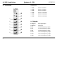
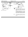
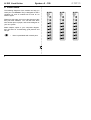
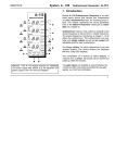
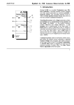
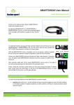
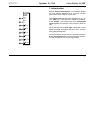
System A - 100
doepfer
Clock Divider A-160
1. Introduction
A-160
CLOCK
DIVIDER
Trig.
In
Res.
In
/2
/4
/8
/ 16
Module A-160 (Clock Divider) is a frequency divider
for clock signals, designed to be a source of lower
frequencies, particularly for rhythm uses.
The Trigger input will take clock signals from, eg., an
LFO, MIDI sync, or the gate from a MIDI-CV interface.
At the outputs, you have access to the sub-divided
clock signals, from half the clock frequency down to
1/64.
The A-160 also has a reset input. Whenever a reset
signal is sensed, all outputs are set to zero, until the
reset voltage disappears.
The Clock Divider can be used in combination with the
A-161 Clock Sequencer to produce stepped sequences with a length of from one to eight events.
/ 32
/ 64
1
A-160 Clock Divider
➁
➂
➃
➄
➅
2
doepfer
Indicators:
2. Overview
➀
System A - 100
1 LED :
Clock / 2 indicator
A-160
2 LED :
Clock / 4 indicator
CLOCK
DIVIDER
Trig.
In
3 LED :
Clock / 8 indicator
4 LED :
Clock / 16 indicator
5 LED :
Clock / 32 indicator
Res.
In
6 LED :
Clock / 64 indicator
/2
In / Outputs:
/4
/8
/ 16
/ 32
/ 64
! Trig. In :
clock signal input
" Res. In :
reset input
§ /2 :
1/2 clock frequency output
$ /4 :
1/4 clock frequency output
% /8 :
1/8 clock frequency output
& /16 :
1/16 clock frequency output
/ /32 :
1/32 clock frequency output
( /64 :
1/64 clock frequency output
doepfer
System A - 100
3. Indicators
1 LED ... 6 LED
LEDs 1 to 6 indicate the status of each of the subdivided frequencies at outputs § to (.
Clock Divider A-160
§ /2 ... ( /64
Sockets § to ( are the A-160 outputs, from which the
sub-divided clock signals are available.
4. In / Outputs
! Trig. In
Trigger input: patch the frequency to be divided in
here.
" Res. In
Socket " is the reset input for the A-160. When a
reset voltage is sensed, all outputs go to zero, for as
long as the reset voltage is present. (ie. a ‘static
reset’)
H
With a Clock Sequencer (A-161) connected,
every time the A-160 senses a reset signal,
the A-161 returns to output ! .
P
With the help of the reset input, you can
produce sequences with less than eight
steps. For instance, by patching output / of
the A-161 to the reset input socket " of the
A-160 you get a six-step sequence. (Instead
of going to step seven, it resets to step one.)
5. User examples
"Ping-Pong" effect
The patch in Fig. 1 produces a "Ping-Pong" effect: with
each note on the keyboard (gate signal) the audio
jumps between left and right outputs - OutL and OutR .
The A-160 is halving the gate frequency, and triggering the A-150 VCS, so that each of its outputs is
active only every other note.
ADSR envelope with re-triggering
In the patch in Fig. 2, an ADSR is re-triggered by a
square wave LFO, sub-divided in the A-160 by a factor
of four (output $). The original whole LFO oscillation is
patched to the re-trigger input on the ADSR. In this
way, a new repeating envelope is created.
3
A-160 Clock Divider
System A - 100
I/ O 1
O/I
A udio
Gat e
A-150
A-131
A-160
Out
I/O 2
CL O CK
L
LFO
DIV IDER
Tri g.
In
Retrigger
Gate
CV
A-160
doepfer
/4
ADSR
A-131
C L OC K
DIV IDER
Tri g.
In
Out
R
/2
ADSR
Fig. 2: ADSR envelope with retriggering
P
By using different outputs on the A-160 it’s
possible to have envelopes re-triggering different numbers of times, from two to thirtytwo.
In addition, by using an A-161, 3-, 5-, 6- or 7step triggering is possible as well. You patch
the A-161’s $, %, & or / output to the gate
input of the ADSR. Output %, &, / or ( is
patched to the A-160’s " reset input socket.
H
Other suggestions for using the A-160 are in
the A-161 Clock Sequencer’s section of the
manual.
Fig. 1: Ping-Pong effect
4
doepfer
System A - 100
Clock Divider A-160
5
A-160 Clock Divider
System A - 100
doepfer
6. Patch-Sheet
The following diagrams of the module can help you
recall your own Patches. They’re designed so that a
complete 19” rack of modules will fit onto an A4
sheet of paper.
Photocopy this page, and cut out the pictures of this
and your other modules. You can then stick them
onto another piece of paper, and create a diagram of
your own system.
Make multiple copies of your composite diagram,
and use them for remembering good patches and
set-ups.
P
6
•
Draw in patchleads with colored pens.
A-160
A-160
A-160
CLOCK
DIVIDER
Trig.
In
CLOCK
DIVIDER
Trig.
In
CLOCK
DIVIDER
Trig.
In
Res.
In
Res.
In
Res.
In
/2
/2
/2
/4
/4
/4
/8
/8
/8
/ 16
/ 16
/ 16
/ 32
/ 32
/ 32
/ 64
/ 64
/ 64