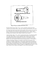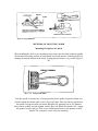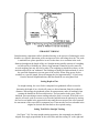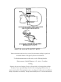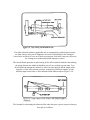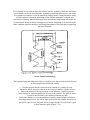
1
INSTRUCTIONS TO LEARN HOW TO USE A
LATHE
The lathe is a machine tool used principally for shaping pieces of metal (and sometimes
wood or other materials) by causing the workpiece to be held and rotated by the lathe
while a tool bit is advanced into the work causing the cutting action. The basic lathe that
was designed to cut cylindrical metal stock has been developed further to produce screw
threads, tapered work, drilled holes, knurled surfaces, and crankshafts. Modern lathes
offer a variety of rotating speeds and a means to manually and automatically move the
cutting tool into the workpiece. Machinists and maintenance shop personnel must be
thoroughly familiar with the lathe and its operations to accomplish the repair and
fabrication of needed parts.
TYPES OF LATHES
Lathes can be divided into three types for easy identification: engine lathe, turret lathe,
and special purpose lathes. Some smaller ones are bench mounted and semi-portable. The
larger lathes are floor mounted and may require special transportation if they must be
moved. Field and maintenance shops generally use a lathe that can be adapted to many
operations and that is not too large to be moved from one work site to another. The
engine lathe (Figure 7-1) is ideally suited for this purpose. A trained operator can
accomplish more machining jobs with the engine lathe than with any other machine tool.
Turret lathes and special purpose lathes are usually used in production or job shops for
mass production or specialized parts, while basic engine lathes are usually used for any
type of lathe work. Further reference to lathes in this chapter will be about the various
engine lathes.
ENGINE LATHES
Sizes
The size of an engine lathe is determined by the largest piece of stock that can be
machined. Before machining a workpiece, the following measurements must be
considered: the diameter of the work that will swing over the bed and the length between
lathe centers (Figure 7-1).
Categories
Slight differences in the various engine lathes make it easy to group them into three
categories: lightweight bench engine lathes, precision tool room lathes, and gap lathes,
which are also known as extension-type lathes. These lathe categories are shown in
Figure 7-2 Different manufacturers may use different lathe categories.
Lightweight
Lightweight bench engine lathes are generally small lathes with a swing of 10 inches or
less, mounted to a bench or table top. These lathes can accomplish most machining jobs,
but may be limited due to the size of the material that can be turned.
Precision
Precision tool room lathes are also known as standard manufacturing lathes and are used
for all lathe operations, such as turning, boring, drilling, reaming, producing screw
threads, taper turning, knurling, and radius forming, and can be adapted for special
milling operations with the appropriate fixture. This type of lathe can handle workpieces
up to 25 inches in diameter and up to 200 inches long. However, the general size is about
a 15-inch swing with 36 to 48 inches between centers. Many tool room lathes are used for
special tool and die production due to the high accuracy of the machine.
GAP OR EXTENSION-TYPE LATHES
Gap or extension-type lathes are similar to toolroom lathes except that gap lathes can be
adjusted to machine larger diameter and longer workpieces The operator can increase the
swing by moving the bed a distance from the headstock, which is usually one or two feet.
By sliding the bed away from the headstock, the gap lathe can be used to turn very long
workpieces between centers.
LATHE COMPONENTS
Engine lathes all have the same general functional parts, even though the specific location
or shape of a certain part may differ from one manufacturer The bed is the foundation of
the working parts of the lathe to another (Figure 7-3).
The main feature of its construction are the ways which are formed on its upper surface
and run the full length of the bed.
Ways provide the means for holding the tailstock and carriage, which slide along the
ways, in alignment with the permanently attached headstock
The headstock is located on the operator's left end of the lathe bed. It contains the main
spindle and oil reservoir and the gearing mechanism for obtaining various spindle speeds
and for transmitting power to the feeding and threading mechanism. The headstock
mechanism is driven by an electric motor connected either to a belt or pulley system or to
a geared system. The main spindle is mounted on bearings in the headstock and is
hardened and specially ground to fit different lathe holding devices. The spindle has a
hole through its entire length to accommodate long workpieces. The hole in the nose of
the spindle usually has a standard Morse taper which varies with the size of the lathe.
Centers, collets, drill chucks, tapered shank drills and reamers may be inserted into the
spindle. Chucks, drive plates, and faceplates may be screwed onto the spindle or clamped
onto the spindle nose.
The tailstock is located on the opposite end of the lathe from the headstock. It supports
one end of the work when machining between centers, supports long pieces held in the
chuck, and holds various forms of cutting tools, such as drills, reamers, and taps. The
tailstock is mounted on the ways and is designed to be clamped at any point along the
ways. It has a sliding spindle that is operated by a hand wheel and clamped in position by
means of a spindle clamp. The tailstock may be adjusted laterally (toward or away from
the operator) by adjusting screws. It should be unclamped from the ways before any
lateral adjustments are made, as this will allow the tailstock to be moved freely and
prevent damage to the lateral adjustment screws.
The carriage includes the apron, saddle, compound rest, cross slide, tool post, and the
cutting tool. It sits across the lathe ways and in front of the lathe bed. The function of the
carriage is to carry and move the cutting tool. It can be moved by hand or by power and
can be clamped into position with a locking nut. The saddle carries the cross slide and the
compound rest. The cross slide is mounted on the dovetail ways on the top of the saddle
and is moved back and forth at 90° to the axis of the lathe by the cross slide lead screw.
The lead screw can be hand or power activated. A feed reversing lever, located on the
carriage or headstock, can be used to cause the carriage and the cross slide to reverse the
direction of travel. The compound rest is mounted on the cross slide and can be swiveled
and clamped at any angle in a horizontal plane. The compound rest is used extensively in
cutting steep tapers and angles for lathe centers. The cutting tool and tool holder are
secured in the tool post which is mounted directly to the compound rest. The apron
contains the gears and feed clutches which transmit motion from the feed rod or lead
screw to the carriage and cross slide.
CARE AND MAINTENANCE OF LATHES
Lathes are highly accurate machine tools designed to operate around the clock if properly
operated and maintained. Lathes must be lubricated and checked for adjustment before
operation. Improper lubrication or loose nuts and bolts can cause excessive wear and
dangerous operating conditions.
The lathe ways are precision ground surfaces and must not be used as tables for other
tools and should be kept clean of grit and dirt. The lead screw and gears should be
checked frequently for any metal chips that could be lodged in the gearing mechanisms.
Check each lathe prior to operation for any missing parts or broken shear pins. Refer to
the operator's instructions before attempting to lift any lathe. Newly installed lathes or
lathes that are transported in mobile vehicles should be properly leveled before any
operation to prevent vibration and wobble. Any lathes that are transported out of a normal
shop environment should be protected from dust, excessive heat, and very cold
conditions. Change the lubricant frequently if working in dusty conditions. In hot
working areas, use care to avoid overheating the motor or damaging any seals. Operate
the lathe at slower speeds than normal when working in cold environments.
SAFETY
All lathe operators must be constantly aware of the safety hazards that are associated with
using the lathe and must know all safety precautions to avoid accidents and injuries.
Carelessness and ignorance are two great menaces to personal safety. Other hazards can
be mechanically related to working with the lathe, such as proper machine maintenance
and setup. Some important safety precautions to follow when using lathes are:
•
•
•
•
•
•
•
•
•
•
•
•
•
•
•
•
•
Correct dress is important, remove rings and watches, roll sleeves above elbows.
Always stop the lathe before making adjustments.
Do not change spindle speeds until the lathe comes to a complete stop.
Handle sharp cutters, centers, and drills with care.
Remove chuck keys and wrenches before operating
Always wear protective eye protection.
Handle heavy chucks with care and protect the lathe ways with a block of wood
when installing a chuck.
Know where the emergency stop is before operating the lathe.
Use pliers or a brush to remove chips and swarf, never your hands.
Never lean on the lathe.
Never lay tools directly on the lathe ways. If a separate table is not available, use
a wide board with a cleat on each side to lay on the ways.
Keep tools overhang as short as possible.
Never attempt to measure work while it is turning.
Never file lathe work unless the file has a handle.
File left-handed if possible.
Protect the lathe ways when grinding or filing.
Use two hands when sanding the workpiece. Do not wrap sand paper or emory
cloth around the workpiece.
TOOLS AND EQUIPMENT
GENERAL PURPOSE CUTTING TOOLS
The lathe cutting tool or tool bit must be made of the correct material and ground to the
correct angles to machine a workpiece efficiently. The most common tool bit is the
general all-purpose bit made of high-speed steel. These tool bits are generally
inexpensive, easy to grind on a bench or pedestal grinder, take lots of abuse and wear,
and are strong enough for all-around repair and fabrication. High-speed steel tool bits can
handle the high heat that is generated during cutting and are not changed after cooling.
These tool bits are used for turning, facing, boring and other lathe operations. Tool bits
made from special materials such as carbides, ceramics, diamonds, cast alloys are able to
machine workpieces at very high speeds but are brittle and expensive for normal lathe
work. High-speed steel tool bits are available in many shapes and sizes to accommodate
any lathe operation.
SINGLE POINT TOOL BITS
Single point tool bits can be one end of a high-speed steel tool bit or one edge of a
carbide or ceramic cutting tool or insert. Basically, a single point cutter bit is a tool that
has only one cutting action proceeding at a time. A machinist or machine operator should
know the various terms applied to the single point tool bit to properly identify and grind
different tool bits (Figure 7-4).
•
•
•
•
•
•
•
•
The shank is the main body of the tool bit.
The nose is the part of the tool bit which is shaped to a point and forms the corner
between the side cutting edge and the end cutting edge. The nose radius is the
rounded end of the tool bit.
The face is the top surface of the tool bit upon which the chips slide as they
separate from the work piece.
The side or flank of the tool bit is the surface just below and adjacent to the
cutting edge.
The cutting edge is the part of the tool bit that actually cuts into the workpiece,
located behind the nose and adjacent to the side and face.
The base is the bottom surface of the tool bit, which usually is ground flat during
tool bit manufacturing.
The end of the tool bit is the near-vertical surface which, with the side of the bit,
forms the profile of the bit. The end is the trailing surface of the tool bit when
cutting.
The heel is the portion of the tool bit base immediately below and supporting the
face.
Angles of Tool Bits
The successful operation of the lathe and the quality of work that may be achieved
depend largely on the angles that form the cutting edge of the tool bit (Figure 7-4). Most
tools are hand ground to the desired shape on a bench or pedestal grinder. The cutting
tool geometry for the rake and relief angles must be properly ground, but the overall
shape of the tool bit is determined by the preference of the machinist or machine
operator. Lathe tool bit shapes can be pointed, rounded, squared off, or irregular in shape
and still cut quite well as long as the tool bit angles are properly ground for the type of
material being machined. The angles are the side and back rake angles, the side and end
cutting edge angles, and the side and end relief angles. Other angles to be considered are
the radius on the end of the tool bit and the angle of the tool holder. After knowing how
the angles affect the cutting action, some recommended cutting tool shapes can be
considered.
Rake angle pertains to the top surface of the tool bit. There are two types of rake angles,
the side and back rake angles (Figure 7-4). The rake angle can be positive, negative, or
have no rake angle at all. The tool holder can have an angle, known as the tool holder
angle, which averages about 15°, depending on the model of tool holder selected. The
tool holder angle combines with the back rake angle to provide clearance for the heel of
the tool bit from the workpiece and to facilitate chip removal. The side rake angle is
measured back from the cutting edge and can be a positive rake angle or have no rake at
all.
Rake angles cannot be too great or the cutting edge will lose strength to support the
cutting action. The side rake angle determines the type and size of chip produced during
the cutting action and the direction that the chip travels when leaving the cutting tool.
Chip breakers can be included in the side rake angle to ensure that the chips break up and
do not become a safety hazard.
Side and relief angles, or clearance angles, are the angles formed behind and beneath the
cutting edge that provide clearance or relief to the cutting action of the tool. There are
two types of relief angles, side relief and end relief. Side relief is the angle ground into
the tool bit, under the side of the cutting edge, to provide clearance in the direction of tool
bit travel. End relief is the angle ground into the tool bit to provide front clearance to
keep the tool bit heel from rubbing. The end relief angle is supplemented by the tool
holder angle and makes up the effective relief angle for the end of the tool bit.
Side and cutting edge angles are the angles formed by the cutting edge with the end of the
tool bit (the end cutting edge angle), or with the side of the tool bit (the side cutting edge
angle). The end cutting edge angle permits the nose of the tool bit to make contact with
the work and aids in feeding the tool bit into the work. The side cutting edge angle
reduces the pressure on the tool bit as it begins to cut. The side rake angle and the side
relief angle combine to form the wedge angle (or lip angle) of the tool bit that provides
for the cutting action (Figure 7-4).
A radius ground onto the nose of the tool bit can help strengthen the tool bit and provide
for a smooth cutting action.
Shapes of Tool Bits
The overall shape of the lathe tool bits can be rounded, squared, or another shape as long
as the proper angles are included. Tool bits are identified by the function they perform,
such as turning or facing. They can also be identified as roughing tools or finishing tools.
Generally, a roughing tool has a radius ground onto the nose of the tool bit that is smaller
than the radius for a finishing or general-purpose tool bit. Experienced machinists have
found the following shapes to be useful for different lathe operations.
A right-hand turning tool bit is shaped to be fed from right to left. The cutting edge is on
the left side of the tool bit and the face slopes down away from the cutting edge. The left
side and end of the tool bit are ground with sufficient clearance to permit the cutting edge
to bear upon the workpiece without the heel rubbing on the work. The right-hand turning
tool bit is ideal for taking light roughing cuts as well as general all-around machining.
A left-hand turning tool bit is the opposite of the right-hand turning tool bit, designed to
cut when fed from left to right. This tool bit is used mainly for machining close in to a
right shoulder.
The round-nose turning tool bit is very versatile and can be used to turn in either direction
for roughing and finishing cuts. No side rake angle is ground into the top face when used
to cut in either direction, but a small back rake angle may be needed for chip removal.
The nose radius is usually ground in the shape of a half-circle with a diameter of about
1/32 inch.
The right-hand facing tool bit is intended for facing on right-hand side shoulders and the
right end of a workpiece. The cutting edge is on the left-hand side of the bit, and the nose
is ground very sharp for machining into a square corner. The direction of feed for this
tool bit should be away from the center axis of the work, not going into the center axis.
A left-hand facing tool bit is the opposite of the right-hand facing tool bit and is intend to
machine and face the left sides of shoulders.
The parting tool bit, Figure 7-6, is also known as the cutoff tool bit. This tool bit has the
principal cutting edge at the squared end of the bit that is advanced at a right angle into
the workpiece. Both sides should have sufficient clearance to prevent binding and should
be ground slightly narrower at the back than at the cutting edge. Besides being used for
parting operations, this tool bit can be used to machine square corners and grooves.
Thread-cutting tool bits, Figure 7-7, are ground to cut the type and style of threads
desired. Side and front clearances must be ground, plus the special point shape for the
type of thread desired. Thread-cutting tool bits can be ground for standard 60° thread
forms or for square, Acme, or special threads. Thread-cutting forms are discussed in
greater detail later in this chapter.
SPECIAL TYPES OF LATHE CUTTING TOOLS
Besides the common shaped tool bits, special lathe operations and heavy production work
require special types of cutting tools. Some of the more common of these tools are listed
below.
Tungsten carbide, tantalum carbide, titanium carbide, ceramic, oxide, and diamondtipped tool bits (Figure 7-8). and cutting tool inserts are commonly used in high-speed
production work when heavy cuts are necessary and where exceptionally hard and tough
materials are encountered. Standard shapes for tipped tool bits are similar to high-speed
steel-cutting tool shapes. Carbide and ceramic inserts can be square, triangular, round, or
other shapes. The inserts are designed to be indexed or rotated as each cutting edge gets
dull and then discarded. Cutting tool inserts are not intended for reuse after sharpening.
Specially formed thread cutter mounted in a thread cutter holder (Figure 7-9). This tool is
designed for production high-speed thread cutting operations. The special design of the
cutter allows for sharp and strong cutting edges which need only to be resharpened
occasionally by grinding the face. The cutter mounts into a special tool holder that
mounts to the lathe tool post.
The common knurling tool, Figure 7-10, consists of two cylindrical cutters, called knurls,
which rotate in a specially designed tool holder. The knurls contain teeth which are rolled
against the surface of the workpiece to form depressed patterns on the workpiece. The
common knurling tool accepts different pairs of knurls, each having a different pattern or
pitch. The diamond pattern is most widely used and comes in three pitches: 14, 21, or 33.
These pitches produce coarse, medium, and fine knurled patterns.
Boring tool bits, Figure 7-11, are ground similar to left-hand turning tool bits and threadcutting tool bits, but with more end clearance angle to prevent the heel of the tool bit
from rubbing against the surface of the bored hole. The boring tool bit is usually clamped
to a boring tool holder, but it can be a one-piece unit . The boring tool bit and tool holder
clamp into the lathe tool post.
There is no set procedure to grinding lathe tool bit angles and shapes, but there are
general guidelines that should be followed. Do not attempt to use the bench or pedestal
grinder without becoming fully educated as to its safety, operation, and capabilities. In
order to effectively grind a tool bit, the grinding wheel must have a true and clean face
and be of the appropriate material for the cutting tool to be ground. Carbide tool bits must
be ground on a silicon carbide grinding wheel to remove the very hard metal.
High-speed steel tool bits are the only tool bits that can effectively be ground on the
bench or pedestal grinder when equipped with the aluminum oxide grinding wheel which
is standard for most field and maintenance shops. Before grinding, shaping, or sharpening
a high-speed steel tool bit, inspect the entire grinder for a safe setup and adjust the tool
rests and guards as needed for tool bit grinding (Figure 7-12).
Set the tool rest 1/8 inch or less from the wheel, and adjust the spark arrestor 1/4 inch or
less. Each grinder is usually equipped with a coarse-grained wheel for rough grinding and
a fine-grained wheel for fine and finish grinding. Dress the face of the grinding wheels as
needed to keep a smooth, flat grinding surface for the tool bit. When grinding the side
and back rake angles, ensure the grinding wheel has a sharp corner for shaping the angle.
Dip the tool bit in water occasionally while grinding to keep the tool bit cool enough to
handle and to avoid changing the property of the metal by overheating. Frequently
inspect the tool bit angles with a protractor or special grinding gage. Grind the tool bit to
the recommended angles in the reference for tool bit geometry (Table 7-l in Appendix A).
After grinding to the finished shape, the tool bit should be honed lightly on an oilstone to
remove any burrs or irregular high spots. The smoother the finish on the cutting tool, the
smoother the finish on the work. Figure 7-13 shows the steps involved in grinding a
round nose tool bit to be used for turning in either direction. As a safety note, never use
the side of the grinding wheel to grind a tool bit, as this could weaken the bonding of the
wheel and cause it to crack and explode.
TOOL HOLDERS AND TOOL POSTS
Lathe tool holders are designed to securely and rigidly hold the tool bit at a fixed angle
for properly machining a workpiece (Figure 7-14). Tool holders are designed to work in
conjunction with various lathe tool posts, onto which the tool holders are mounted. Tool
holders for high speed steel tool bits come in various types for different uses. These tool
holders are designed to be used with the standard round tool post that usually is supplied
with each engine lathe (Figure 7-15 ). This tool post consists of the post, screw, washer,
collar, and rocker, and fits into the T-slot of the compound rest.
Standard tool holders for high-speed steel cutting tools have a square slot made to fit a
standard size tool bit shank. Tool bit shanks can be 1/4-inch, 5/16-inch, 3/8-inch, and
greater, with all the various sizes being manufactured for all the different lathe
manufacturer's tool holder models. Some standard tool holders for steel tool bits are the
straight tool holder, right and left offset tool holder, and the zero rake tool holder
designed for special carbide tool bits. Other tool holders to fit the standard round tool
post include straight, left, and right parting tool holders, knurling tool holders, boring bar
tool holders, and specially formed thread cutting tool holders.
The turret tool post (Figure 7-16 ) is a swiveling block that can hold many different tool
bits or tool holders. Each cutting tool can quickly be swiveled into cutting position and
clamped into place using a quick clamping handle. The turret tool post is used mainly for
high-speed production operations.
The heavy-duty or open-sided tool post (Figure 7-17) is used for holding a single carbidetipped tool bit or tool holder. It is used mainly for very heavy cuts that require a rigid tool
holder.
The quick-change tool system (Figure 7-18) consists of a quick-change dovetail tool post
with a complete set of matching dovetailed tool holders that can be quickly changed as
different lathe operations become necessary. This system has a quick-release knob on the
top of the tool post that allows tool changes in less than 5 seconds, which makes this
system valuable for production machine shops.
WORK HOLDING DEVICES
Many different devices, such as chucks, collets, faceplates, drive plates, mandrels, and
lathe centers, are used to hold and drive the work while it is being machined on a lathe.
The size and type of work to be machined and the particular operation that needs to be
done will determine which work holding device is best for any particular job. Another
consideration is how much accuracy is needed for a job, since some work holding devices
are more accurate than others. Operational details for some of the more common work
holding devices follow.
The universal scroll chuck, Figure 7-19, usually has three jaws which move in unison as
an adjusting pinion is rotated. The advantage of the universal scroll chuck is its ease of
operation in centering work for concentric turning. This chuck is not as accurate as the
independent chuck, but when in good condition it will center work within 0.002 to 0.003
inches of runout.
The jaws are moved simultaneously within the chuck by a scroll or spiral-threaded plate.
The jaws are threaded to the scroll and move an equal distance inward or outward as the
scroll is rotated by the adjusting pinion. Since the jaws are individually aligned on the
scroll, the jaws cannot usually be reversed. Some manufactures supply two sets of jaws,
one for internal work and one for external work. Other manufactures make the jaws in
two pieces so the outside, or gripping surface may be reversed. which can be
interchanged.
The universal scroll chuck can be used to hold and automatically center round or
hexagonal workpieces. Having only three jaws, the chuck cannot be used effectively to
hold square, octagonal, or irregular shapes.
The independent chuck, Figure 7-19, generally has four jaws which are adjusted
individually on the chuck face by means of adjusting screws. The chuck face is scribed
with concentric circles which are used for rough alignment of the jaws when chucking
round workpieces. The final adjustment is made by turning the workpiece slowly by hand
and using a dial indicator to determine it's concentricity. The jaws are then readjusted as
necessary to align the workpiece within the desired tolerances.
The jaws of the independent chuck may be used as illustrated or may be reversed so that
the steps face in the opposite direction; thus workpieces can be gripped either externally
or internally. The independent chuck can be used to hold square, round, octagonal, or
irregularly shaped workpieces in either a concentric or eccentric position due to the
independent operation of each jaw.
Because of its versatility and capacity for fine adjustment, the independent chuck is
commonly used for mounting odd-shaped workpieces which must be held with extreme
accuracy.
A combination chuck combines the features of the independent chuck and the universal
scroll chuck and can have either three or four jaws. The jaws can be moved in unison on
a scroll for automatic centering or can be moved individually if desired by separate
adjusting screws.
The drill chuck, Figure 7-19, is a small universal chuck which can be used in either the
headstock spindle or the tailstock for holding straight-shank drills, reamers, taps, or small
diameter workpieces. The drill chuck has three or four hardened steel jaws which are
moved together or apart by adjusting a tapered sleeve within which they are contained.
The drill chuck is capable of centering tools and small-diameter workpieces to within
0.002 or 0.003 inch when firmly tightened.
The collet chuck is the most accurate means of holding small workpieces in the lathe. The
collet chuck consists of a spring machine collet (Figure 7-20) and a collet attachment
which secures and regulates the collet on the headstock spindle of the lathe.
The spring machine collet is a thin metal bushing with an accurately machined bore and a
tapered exterior. The collet has three lengthwise slots to permit its sides being sprung
slightly inward to grip the workpiece. To grip the workpiece accurately, the collet must
be no more than 0.005 inch larger or smaller than the diameter of the piece to be chucked.
For this reason, spring machine collets are available in increments of 1/64 inch. For
general purposes, the spring machine collets are limited in capacity to 1 1/8 inch in
diameter.
For general purposes, the spring machine collets are limited in capacity to 1 1/8 inch in
diameter.
The collet attachment consists of a collet sleeve, a drawbar, and a handwheel or hand
lever to move the drawbar. The spring machine collet and collet attachment together form
the collet chuck. Figure 7-20 illustrates a typical collet chuck installation. The collet
sleeve is fitted to the right end of the headstock spindle. The drawbar passes through the
headstock spindle and is threaded to the spring machine collet. When the drawbar is
rotated by means of the hand wheel, it draws the collet into the tapered adapter, causing
the collet to tighten on the workpiece. Spring machine collets are available in different
shapes to chuck square and hexagonal workpieces of small dimensions as well as round
workpieces.
The Jacob's spindle-nose collet chuck (Figure 7-21) is a special chuck is used for the
Jacob's rubber flex collets. This chuck combines the functions of the standard collet
chuck and drawbar into one single compact unit. The chuck housing has a handwheel on
the outer diameter that turns to tighten or loosen the tapered spindle which holds the
rubber flex collets. Rubber flex collets are comprised of devices made of hardened steel
jaws in a solid rubber housing. These collets have a range of 1/8 inch per collet. The
gripping power and accuracy remain constant throughout the entire collet capacity.
Jacob's rubber flex collets are designed for heavy duty turning and possess two to four
times the grip of the conventional split steel collet. The different sets of these collets are
stored in steel boxes designed for holding the collets. Collets are normally stored in steel
boxes designed for holding the collets.
The step chuck, Figure 7-22, is a variation of the collet chuck, and it is intended for
holding small round workpieces or discs for special machining jobs. Step chucks are
blank when new, and then are machined in the lathe for an exact fit for the discs to be
turned. The step chuck machine collet, which is split into three sections like the spring
machine collet, is threaded to the drawbar of the collet attachment.
The lathe tailstock chuck, Figure 7-22, is a device designed to support the ends of
workpieces in the tailstock when a lathe center cannot be used conveniently. The chuck
has a taper arbor that fits into the lathe tailstock spindle. The three bronze self-centering
jaws of the chuck will accurately close upon workpieces between 1/4 and 1 inch in
diameter. The bronze jaws provide a good bearing surface for the workpiece. The jaws
are adjusted to the diameter of the workpiece and then locked in place.
A lathe faceplate, Figure 7-23, is a flat, round plate that threads to the headstock spindle
of the lathe. The faceplate is used for irregularly shaped workpieces that cannot be
successfully held by chucks or mounted between centers. The workpiece is either
attached to the faceplate using angle plates or brackets or bolted directly to the plate.
Radial T-slots in the faceplate surface facilitate mounting workpieces. The faceplate is
valuable for mounting workpieces in which an eccentric hole or projection is to be
machined. The number of applications of the faceplates depends upon the ingenuity of
the machinist. A small faceplate known as a driving faceplate is used to drive the lathe
dog for workpieces mounted between centers. The driving faceplate usually has fewer Tslots than the larger faceplates. When the workpiece is supported between centers, a lathe
dog is fastened to the workpiece and engaged in a slot of the driving faceplate.
Lathe centers, Figure 7-24, are the most common devices for supporting workpieces in
the lathe. Most lathe centers have a tapered point with a 60° included angle to fit
workpiece holes with the same angle. The workpiece is supported between two centers,
one in the headstock spindle and one in the tailstock spindle. Centers for lathe work have
standard tapered shanks that fit directly into the tailstock and into the headstock spindle
using a center sleeve to convert the larger bore of the spindle to the smaller tapered size
of the lathe center. The centers are referred to as live centers or dead centers. A live
center revolves with the work and does not need to be lubricated and hardened. A dead
center does not revolve with the work and must be hardened and heavily lubricated when
holding work. Live and dead centers commonly come in matched sets, with the hardened
dead center marked with a groove near the conical end point.
The ball bearing live center is a special center mounted in a ball bearing housing that lets
the center turn with the work and eliminates the need for a heavily lubricated dead center.
Ball bearing types of centers can have interchangeable points which make this center a
versatile tool in all lathe operations. Modern centers of this type can be very accurate.
Descriptions for some common lathe centers follow.
The male center or plain center is used in pairs for most general lathe turning operations.
The point is ground to a 60° cone angle. When used in the headstock spindle where it
revolves with the workpiece, it is commonly called a live center. When used in the
tailstock spindle where it remains stationary when the workpiece is turned, it is called a
dead center. Dead centers are always made of hardened steel and must be lubricated very
often to prevent overheating.
The half male center is a male center that has a portion of the 60° cone cut away. The half
male center is used as a dead center in the tailstock where facing is to be performed. The
cutaway portion of the center faces the cutting tool and provides the necessary clearance
for the tool when facing the surface immediately around the drilled center in the
workpiece.
The V-center is used to support round workpieces at right angles to the lathe axis for
special operations such as drilling or reaming. The pipe center is similar to the male
center but its cone is ground to a greater angle and is larger in size. It is used for holding
pipe and tubing in the lathe. The female center is conically bored at the tip and is used to
support workpieces that are pointed on the end. A self-driving lathe center is a center
with serrated ground sides that can grip the work while turning between centers without
having to use lathe dogs.
A self driving center is a center that has grips installed on the outer edge of the center
diameter that can be forced into the work to hold and drive the work when turning
between centers without using lathe dogs.
Lathe dogs are cast metal devices used to provide a firm connection between the
headstock spindle and the workpiece mounted between centers. This firm connection
permits the workpiece to be driven at the same speed as the spindle under the strain of
cutting. Three common lathe dogs are illustrated in Figure 7-25. Lathe dogs may have
bent tails or straight tails. When bent-tail dogs are used, the tail fits into a slot of the
driving faceplate. When straight-tail dogs are used, the tail bears against a stud projecting
from the faceplate. The bent-tail lathe dog with headless setscrew is considered safer than
the dog with the square head screw because the headless setscrew reduces the danger of
the dog catching in the operator's clothing and causing an accident. The bent-tail clamp
lathe dog is used primarily for rectangular workpieces.
MANDRELS
A workpiece which cannot be held between centers because its axis has been drilled or
bored, and which is not suitable for holding in a chuck or against a faceplate, is usually
machined on a mandrel. A mandrel is a tapered axle pressed into the bore of the
workpiece to support it between centers.
A mandrel should not be confused with an arbor, which is a similar device but used for
holding tools rather than workpieces. To prevent damage to the work, the mandrel should
always be oiled before being forced into the hole. When turning work on a mandrel, feed
toward the large end which should be nearest the headstock of the lathe.
A solid machine mandrel is generally made from hardened steel and ground to a slight
taper of from 0.0005 to 0.0006 inch per inch. It has very accurately countersunk centers
at each end for mounting between centers. The ends of the mandrel are smaller than the
body and have machined flats for the lathe dog to grip. The size of the solid machine
mandrel is always stamped on the large end of the taper. Since solid machine mandrels
have a very slight taper, they are limited to workpieces with specific inside diameters.
An expansion mandrel will accept workpieces having a greater range of sizes. The
expansion mandrel is, in effect, a chuck arranged so that the grips can be forced outward
against the interior of the hole in the workpiece.
LATHE ATTACHMENTS
The variety of work that can be performed on the lathe is greatly increased by the use of
various lathe attachments. Some lathes come equipped with special attachments; some
attachments must be ordered separately. Some common lathe attachments are the steady
rest with cathead, the follower rest, the tool post grinding machine, the lathe micrometer
stop, the lathe milling fixture, the lathe coolant attachment, the lathe indexing fixture, and
the milling-grinding-drilling-slotting attachment (or Versa-Mil). The lathe indexing
fixture and Versa-Mil unit are detailed in Chapter 9. Descriptions for the other lathe
attachments follows.
RESTS
Workpieces often need extra support, especially long, thin workpieces that tend to spring
away from the tool bit. Three common supports or rests are the steady rest, the cathead,
and the follower rest (Figure 7-27).
Steady Rest
The steady rest, also called a center rest, is used to support long workpieces for turning
and boring operations. It is also used for internal threading operations where the
workpiece projects a considerable distance from the chuck or faceplate. The steady rest is
clamped to the lathe bed at the desired location and supports the workpiece within three
adjustable jaws. The workpiece must be machined with a concentric bearing surface at
the point where the steady rest is to be applied. The jaws must be carefully adjusted for
proper alignment and locked in position. The area of contact must be lubricated
frequently. The top section of the steady rest swings away from the bottom section to
permit removal of the workpiece without disturbing the jaw setting.
Cathead
When the work is too small to machine a bearing surface for the adjustable jaws to hold,
then a cathead should be used. The cathead has a bearing surface, a hole through which
the work extends, and adjusting screws. The adjusting screws fasten the cathead to the
work. They are also used to align the bearing surface so that it is concentric to the work
axis. A dial indicator must be used to set up the cathead to be concentric and accurate.
Follower Rest
The follower rest has one or two jaws that bear against the workpiece. The rest is
fastened to the lathe carriage so that it will follow the tool bit and bear upon the portion
of the workpiece that has just been turned. The cut must first be started and continued for
a short longitudinal distance before the follower rest may be applied. The rest is generally
used only for straight turning and for threading long, thin workpieces. Steady rests and
follower rests can be equipped with ball-bearing surfaces on the adjustable jaws. These
types of rests can be used without excessive lubricant or having to machine a polished
bearing surface.
Micrometer Carriage Stop
The micrometer carriage stop, Figure 7-28, is used to accurately position the lathe
carriage. The micrometer stop is designed so the carriage can be moved into position
against the retractable spindle of the stop and locked into place. A micrometer gage on
the stop enables carriage movement of as little as 0.001 inch. This tool is very useful
when facing work to length, turning a shoulder, or cutting an accurate groove.
Tool Post Grinder
The tool post grinder (Figure 7-29) is a machine tool attachment specially designed for
cylindrical grinding operations on the lathe. It consists primarily of a 1/4-or 1/3horsepower electric motor and a wheel spindle connected by pulleys and a belt. The
machine fastens to the compound rest of the lathe with a T-slot bolt which fits in the slot
of the compound rest in the same manner as the lathe tool post. The tool post grinding
machine mounts grinding abrasive wheels ranging from 1/4 inch to 3 or 4 inches in
diameter for internal and external grinding operations. The pulleys on the wheel spindle
and motor shaft are interchangeable to provide proper cutting speeds for the various
wheel sizes. The larger grinding abrasive wheels used for external grinding are attached
to the wheel spindle with an arbor. Small, mounted grinding abrasive wheels for internal
grinding are fixed in a chuck which screws to the wheel spindle. The electric motor is
connected to an electrical power source by a cable and plug. A switch is usually provided
at the attachment to facilitate starting and stopping the motor.
Lathe Milling Fixture
This is a fixture designed to provide the ability for limited milling operations. Many
repair and fabrication jobs cannot be satisfactorily completed on the standard engine
lathe, but with the lathe milling attachment, the small machine shop that is not equipped
with a milling machine can mill keyslots, keyways, flats, angles, hex heads, squares,
splines, and holes. For specific operating instructions and parts, refer to TM 9-3465-20010.
TOOLS NECESSARY FOR LATHE WORK
In order to properly setup and operate most engine lathes, it is recommended to have the
following tools on hand. A machinist tool box with all wrenches, screwdrivers, and
common hand tools. A dial indicator may be necessary for some procedures on the lathe.
References, charts, tables, and other predetermined data on machine operations may be
useful to lathe operators. Keep all safety equipment, along with necessary cleaning
marking, and lubricating equipment, in the immediate lathe area to use as needed.
CUTTING FLUIDS
The purposes of using cutting fluids on the lathe are to cool the tool bit and workpiece
that are being machined, increase the life of the cutting tool, make a smoother surface
finish, deter rust, and wash away chips. Cutting fluids can be sprayed, dripped, wiped, or
flooded onto the point where the cutting action is taking place. Generally, cutting fluids
should only be used if the speed or cutting action requires the use of cutting fluids.
Descriptions of some common cutting fluids used on the lathe follow. Use Table 4-3 in
Appendix A for additional information on cutting fluids.
Lard Oil
Pure lard oil is one of the oldest and best cutting oils. It is especially good for thread
cutting, tapping, deep hole drilling, and reaming. Lard oil has a high degree of adhesion
or oiliness, a relatively high specific heat, and its fluidity changes only slightly with
temperature. It is an excellent rust preventive and produces a smooth finish on the
workpiece. Because lard oil is expensive, it is seldom used in a pure state but is combined
with other ingredients to form good cutting oil mixtures.
Mineral Oil
Mineral oils are petroleum-base oils that range in viscosity from kerosene to light
paraffin oils. Mineral oil is very stable and does not develop disagreeable odors like lard
oil; however, it lacks some of the good qualities of lard oil such as adhesion, oiliness, and
high specific heat. Because it is relatively inexpensive, it is commonly mixed with lard
oil or other chemicals to provide cutting oils with desirable characteristics. Two mineral
oils, kerosene and turpentine, are often used alone for machining aluminum and
magnesium. Paraffin oil is used alone or with lard oil for machining copper and brass.
Mineral-Lard Cutting Oil Mixture
Various mixtures of mineral oils and lard oil are used to make cutting oils which combine
the good points of both ingredients but prove more economical and often as effective as
pure lard oil.
Sulfurized Fatty-Mineral Oil
Most good cutting oils contain mineral oil and lard oil with various amounts of sulfur and
chlorine which give the oils good antiweld properties and promote free machining. These
oils play an important part in present-day machining because they provide good finishes
on most materials and aid the cutting of tough material.
Soluble Cutting Oils
Water is an excellent cooling medium but has little lubricating value and hastens rust and
corrosion. Therefore, mineral oils or lard oils which can be mixed with water are often
used to form a cutting oil. A soluble oil and water mix has lubricating qualities dependent
upon the strength of the solution. Generally, soluble oil and water is used for rough
cutting where quick dissipation of heat is most important. Borax and trisodium phosphate
(TSP) are sometimes added to the solution to improve its corrosion resistance.
Soda-Water Mixtures
Salts such as soda ash and TSP are sometimes added to water to help control rust. This
mixture is the cheapest of all coolants and has practically no lubricating value. Lard oil
and soap in small quantities are sometimes added to the mixture to improve its lubricating
qualities. Generally, soda water is used only where cooling is the prime consideration and
lubrication a secondary consideration. It is especially suitable in reaming and threading
operations on cast iron where a better finish is desired.
White Lead and Lard Oil Mixture
White lead can be mixed with either lard oil or mineral oil to form a cutting oil which is
especially suitable for difficult machining of very hard metals.
LAYING OUT AND MOUNTING WORK
There is relatively little layout work to be done for most lathe work because of the lathe's
ability to guide the cutting tool accurately to the workpiece. If center holes must be
located and drilled into the end of a workpiece for turning lay out and center-punch the
workpiece using other methods. Some suggested methods are to use a bell-type center
punch between centers and this cannot be accomplished on the lathe, (Figure 7-32), use
hermaphrodite calipers to scribe intersecting arcs, use the centering head of the
combination square, or use dividers (Figure 7-33).
METHODS OF MOUNTING WORK
Mounting Workpieces in Chucks
When installing the chuck or any attachment that screws onto the lathe headstock spindle,
the threads and bearing surfaces of both spindle and chuck must be cleaned and oiled. In
cleaning the internal threads of the chuck, a spring thread cleaner is very useful (Figure 734).
Turn the spindle so that the key is facing up and lock the spindle in position. Make sure
that the spindle and chuck taper are free of grit and chips. Place the chuck in position on
the spindle. Engage the draw nut thread and tighten by applying four or five hammer
blows on the spanner wrench engaged with the draw nut. Rotate the spindle 180°, engage
the spanner wrench, and give four or five solid hammer blows to the spanner wrench
handle. The workpiece is now ready for mounting.
Work automatically centers itself in the universal (3 jaw) scroll chuck, drill chuck, collet
chucks, and step chuck, but must be manually centered in the independent (4 jaw) chuck.
To center work in the independent chuck, line the four jaws up to the concentric rings on
the face of the chuck, as close to the required diameter as possible.
Mount the workpiece and tighten the jaws loosely onto the workpiece (Figure 7-35). Spin
the workpiece by hand and make approximate centering adjustments as needed, then
firmly tighten the jaws.
For rough centering irregularly shaped work, first measure the outside diameter of the
workpiece, then open the four jaws of the chuck until the workpiece slides in. Next
tighten each opposing jaw a little at a time until the workpiece is held firmly, but not too
tightly. Hold a piece of chalk near the workpiece and revolve the chuck slowly with your
left hand. Where the chalk touches is considered the high side.
Loosen the jaw opposite and tighten the jaw where the chalk marks are found. Repeat the
process until the workpiece is satisfactorily aligned.
To center a workpiece having a smooth surface such as round stock, the best method is to
use a dial test indicator. Place the point of the indicator against the outside or inside
diameter of the workpiece. Revolve the workpiece slowly by hand and notice any
deviations on the dial. This method will indicate any inaccuracy of the centering in
thousandths of an inch.
If an irregularly shaped workpiece is to be mounted in the independent chuck, then a
straight, hardened steel bar can be used with a dial indicator to align the workpiece.
Experienced machinists fabricate several sizes of hardened steel bars, ground with a 60°
point, that can be mounted into the drill chuck of the tailstock spindle and guided into the
center-punched mark on the workpiece. A dial indicator can then be used to finish
aligning the workpiece to within 0.001 inch. If a hardened steel bar is not readily
available, a hardened center mounted in the tailstock spindle may be used to align the
work while using a dial indicator on the chuck jaws. This method is one of several ways
to align a workpiece in an independent chuck. Ingenuity and experience will increase the
awareness of the machine operator to find the best method to set up the work for
machining.
When removing chucks from the lathe, always use a wooden chuck block under the
chuck to support the chuck on the lathe ways. Use care to avoid dropping the chuck on
the ways, since this can greatly damage the lathe ways or crush the operator's hands.
Mounting Work to Faceplates
Mount faceplates in the same manner as chucks. Check the accuracy of the faceplate
surface using a dial indicator, and true the-faceplate surface by taking a light cut if
necessary. Do not use faceplates on different lathes, since this will cause excessive wear
of the faceplate due to repeated truing cuts having to be taken. Mount the workpiece
using T-bolts and clamps of the correct sizes (Figure 7-36 ). Ensure all surfaces are wiped
clean of burrs, chips, and dirt. When a heavy piece of work is mounted off center, such as
when using an angle plate, use a counterweight to offset the throw of the work and to
minimize vibration and chatter. Use paper or brass shims between the work and the
faceplate to protect the delicate surface of the faceplate. After mounting the work to an
approximate center location, use a dial indicator to finish accurate alignment.
Mounting Work Between Centers
Before mounting a work-piece between centers, the workpiece ends must be centerdrilled and countersunk. This can be done using a small twist drill followed by a 60°
center countersink or, more commonly, using a countersink and drill (also commonly
called a center drill). It is very important that the center holes are drilled and countersunk
so that they will fit the lathe centers exactly. Incorrectly drilled holes will subject the
lathe centers to unnecessary wear and the workpiece will not run true because of poor
bearing surfaces. A correctly drilled and countersunk hole has a uniform 60° taper and
has clearance at the bottom for the point of the lathe center. Figure 7-37 illustrates
correctly and incorrectly drilled center holes. The holes should have a polished
appearance so as not to score the lathe centers. The actual drilling and countersinking of
center holes can be done on a drilling machine or on the lathe itself. Before attempting to
center drill using the lathe, the end of the workpiece must be machined flat to keep the
center drill from running off center.
Mount the work in a universal or independent chuck and mount the center drill in the
lathe tailstock (Figure 7-38). Refer to the section of this chapter on facing and drilling on
the lathe, prior to doing this operation. Center drills come in various sizes for different
diameters of work (Figure 7-39). Calculate the correct speed and hand feed into the
workpiece. Only drill into the workpiece about 2/3 of the body diameter. high speeds and
feed them into the work slowly to avoid breaking off the drill point inside the work. If
this happens, the work must be removed from the chuck and the point extracted. This is a
time-consuming job and could ruin the workpiece.
To mount work between centers, the operator must know how to insert and remove lathe
centers. The quality of workmanship depends as much on the condition of the lathe
centers as on the proper drilling of the center holes. Before mounting lathe centers in the
headstock or tailstock, thoroughly clean the centers, the center sleeve, and the tapered
sockets in the headstock and tailstock spindles. Any dirt or chips on the centers or in their
sockets will prevent the centers from seating properly and will cause the centers to run
out of true.
Install the lathe center in the tailstock spindle with a light twisting motion to ensure a
clean fit. Install the center sleeve into the headstock spindle and install the lathe center
into the center sleeve with a light twisting motion.
To remove the center from the headstock spindle, hold the pointed end with a cloth or rag
in one hand and give the center a sharp tap with a rod or knockout bar inserted through
the hollow headstock spindle.
To remove the center from the tailstock, turn the tailstock handwheel to draw the
tailstock spindle into the tailstock. The center will contact the tailstock screw and will be
bumped loose from its socket.
After mounting the headstock and tailstock centers, the accuracy of the 60° point should
be checked using a center gage or a dial indicator. If the center in the headstock is not at
60°, or is scarred and burred, it must be trued while inserted in the lathe headstock
spindle. If the headstock center is a soft center (a center that is not heat-treated and
hardened), it can be turned true with the lathe tool bit. If the center in the headstock is
hardened, it must be ground with a tool post grinding machine to get a true surface
(Figure 7-40).
To turn a soft center true with the lathe, first set up the tool bit for right hand turning,
center the tool bit; then, rotate the compound rest to an angle of 30° to the axis of the
lathe (Figure 7-41). The lathe speed should be set for a finish cut, and the feed is supplied
by cranking the handwheel of the compound rest, thus producing a clean and short steep
taper with an included angle of 60°. Once trued, the center should stay in place until the
operation is completed. If the center must be removed, mark the position on the center
and headstock for easy realignment later.
Lathe centers must be parallel with the ways of the lathe in order to turn workpieces
straight and true. Before beginning each turning operation, the center alignment should be
checked.
The tailstock may be moved laterally to accomplish this alignment by means of adjusting
screws after it has been released from the ways. Two zero lines are located at the rear of
the tailstock and the centers are approximately aligned when these lines coincide (Figure
7-42). This alignment may be checked by moving the tailstock up close to the headstock
so that the centers almost touch, and observing their relative positions (Figure 7-42).
The most accurate method of checking alignment of centers is by mounting the
workpiece between centers and taking light cuts at both ends without changing the
carriage adjustments. Measure each end of this cut with calipers or a micrometer. If the
tailstock end is greater in diameter than the headstock end, the tailstock is moved toward
the operator. If the tailstock end is smaller in diameter than the headstock end, the
tailstock is moved away from the operator. Take additional cuts in the same manner after
each adjustment until both cuts measure the same.
To setup the workpiece between centers on the lathe, a driving faceplate (drive plate) and
lathe dog must be used.
(Figure 7-43). Make headstock spindle are faceplate. Screw the sure that the external
threads of the clean before screwing on the driving faceplate securely onto the spindle.
Clamp the lathe dog on the workpiece so that its tail hangs over the end of the workpiece.
If the workpiece is finished, place a shim of soft material such as brass between the
setscrew of the dog and workpiece. Mount the workpiece between the centers. Make sure
that the lathe dog tail tits freely in the slot of the faceplate and does not bind. Sometimes,
the tailstock center is a dead center and does not revolve with the workpiece, so it may
require lubrication. A few drops of oil mixed with white lead should be applied to the
center before the workpiece is set up. The tailstock should be adjusted so that the
tailstock center fits firmly into the center hole of the workpiece but does not bind. The
lathe should be stopped at intervals and additional oil and white lead mixture applied to
the dead center to prevent overheating harm to the center and the workpiece.
Mounting Work on Mandrels
To machine a workpiece of an odd shape, such as a wheel pulley, a tapered mandrel is
used to hold and turn the work. The mandrel must be mounted between centers and a
drive plate and lathe dog must be used. The centers must be aligned and the mandrel must
be free of burrs. Mount the workpiece onto a lubricated mandrel of the proper size by
using an arbor press. Ensure that the lathe dog is secured to the machined flat on the end
of the mandrel and not on the smooth surface of the mandrel taper (Figure 7-44). If
expansion bushings are to be used with a mandrel, clean and care for the expansion
bushings in the same manner as a normal mandrel.
Always feed the tool bit in the direction of the large end of the mandrel, which is usually
toward the headstock end, to avoid pulling the work out of the mandrel. If facing on a
mandrel, avoid cutting into the mandrel with the tool bit..
GENERAL LATHE OPERATIONS
LATHE SPEEDS, FEEDS, AND DEPTH OF CUTS
General operations on the lathe include straight and shoulder turning, facing, grooving,
parting, turning tapers, and cutting various screw threads. Before these operations can be
done, a thorough knowledge of the variable factors of lathe speeds, feeds, and depth of
cut must be understood. These factors differ for each lathe operation, and failure to use
these factors properly will result in machine failure or work damage. The kind of material
being worked, the type of tool bit, the diameter and length of the workpiece, the type of
cut desired (roughing or finishing), and the working condition of the lathe will determine
which speed, feed, or depth of cut is best for any particular operation. The guidelines
which follow for selecting speed, feed, and depth of cut are general in nature and may
need to be changed as conditions dictate.
Cutting Speeds.
The cutting speed of a tool bit is defined as the number of feet of workpiece surface,
measured at the circumference, that passes the tool bit in one minute. The cutting speed,
expressed in FPM, must not be confused with the spindle speed of the lathe which is
expressed in RPM. To obtain uniform cutting speed, the lathe spindle must be revolved
faster for workpieces of small diameter and slower for workpieces of large diameter. The
proper cutting speed for a given job depends upon the hardness of the material being
machined, the material of the tool bit, and how much feed and depth of cut is required.
Cutting speeds for metal are usually expressed in surface feet per minute, measured on
the circumference of the work. Spindle revolutions per minute (RPM) are determined by
using the formula:
Which is simplified to:
Where SFM is the rated surface feet per minute, also expressed as cutting speed.
RPM is the spindle speed in revolutions per minute
D is the diameter of the work in inches.
In order to use the formula simply insert the cutting speed of the metal and the diameter
of the workpiece into the formula and you will have the RPM.
Turning a one-half inch piece of aluminum, cutting speed of 200 SFM, would result in
the following:
Table 7-2 in Appendix A lists specific ranges of cutting speeds for turning and threading
various materials under normal lathe conditions, using normal feeds and depth of cuts.
Note that in Table 7-2 the measurement calculations are in inch and metric measures. The
diameter measurements used in these calculations are the actual working diameters that
are being machined, and not necessarily the largest diameter of the material. The cutting
speeds have a wide range so that the lower end of the cutting speed range can be used for
rough cutting and the higher end for finish cutting. If no cutting speed tables are
available, remember that, generally, hard materials require a slower cutting speed than
soft or ductile materials. Materials that are machined dry, without coolant, require a
slower cutting speed than operations using coolant. Lathes that are worn and in poor
condition will require slower speeds than machines that are in good shape. If carbide-
tipped tool bits are being used, speeds can be increased two to three times the speed used
for high-speed tool bits.
Feed
Feed is the term applied to the distance the tool bit advances along the work for each
revolution of the lathe spindle. Feed is measured in inches or millimeters per revolution,
depending on the lathe used and the operator's system of measurement. Table 7-3 in
Appendix A is a guide that can be used to select feed for general roughing and finishing
operations. A light feed must be used on slender and small workpieces to avoid damage.
If an irregular finish or chatter marks develop while turning, reduce the feed and check
the tool bit for alignment and sharpness. Regardless of how the work is held in the lathe,
the tool should feed toward the headstock. This results in most of the pressure of the cut
being put on the work holding device. If the cut must be fed toward the tailstock, use
light feeds and light cuts to avoid pulling the workpiece loose.
Depth of Cut
Depth of cut is the distance that the tool bit moves into the work, usually measured in
thousandths of an inch or in millimeters. General machine practice is to use a depth of cut
up to five times the rate of feed, such as rough cutting stainless steel using a feed of 0.020
inch per revolution and a depth of cut of 0.100 inch, which would reduce the diameter by
0.200 inch. If chatter marks or machine noise develops, reduce the depth of cut.
MICROMETER COLLAR
Graduated micrometer collars can be used to accurately measure this tool bit movement
to and away from the lathe center axis. Thus, the depth of cut can be accurately measured
when moving the tool bit on the cross slide by using the cross slide micrometer collar.
The compound rest is also equipped with a micrometer collar. These collars can measure
in inches or in millimeters, or they can be equipped with a dual readout collar that has
both. Some collars measure the exact tool bit movement, while others are designed to
measure the amount of material removed from the workpiece (twice the tool bit
movement). Consult the operator's instruction manual for specific information on
graduated collar use.
FACING
Facing is machining the ends and shoulders of a piece of stock smooth, flat, and
perpendicular to the lathe axis. Facing is used to cut work to the desired length and to
produce a surface from which accurate measurements may be taken.
Facing Work in a Chuck
Facing is usually performed with the work held in a chuck or collet. Allow the workpiece
to extend a distance no more than 1 1/2 times the work diameter from the chuck jaws, and
use finishing speeds and feeds calculated using the largest diameter of the workpiece. The
tool bit may be fed from the outer edge to the center or from the center to the outer edge.
Normal facing is done from the outer edge to the center since this method permits the
operator to observe the tool bit and layout line while starting the cut. This method also
eliminates the problem of feeding the tool bit into the solid center portion of the
workpiece to get a cut started.. Use a left-hand finishing tool bit and a right-hand tool
holder when facing from the outer edge toward the center. Work that has a drilled or
bored hole in the center may be faced from the center out to the outer edge if a right-hand
finishing tool bit is used. Avoid excessive tool holder and tool bit overhang when setting
up the facing operation. Set the tool bit exactly on center to avoid leaving a center nub on
the workpiece (Figure 7-46 ). Use the tailstock center point as a reference point when
setting the tool bit exactly on center. If no tailstock center is available, take a trial cut and
readjust as needed. If using the cross slide power feed to move the tool bit (into the
center), disengage power when the tool bit is within l/16 inch of the center and finish the
facing cut using hand feed.
Facing Work Between Centers
Sometimes the workpiece will not fit into a chuck or collet, so facing must be done
between centers. To properly accomplish facing between centers, the workpiece must be
center-drilled before mounting into the lathe. A half male center (with the tip well
lubricated with a white lead and oil mixture) must be used in the lathe tailstock to provide
adequate clearance for the tool bit. The tool bit must be ground with a sharp angle to
permit facing to the very edge of the center drilled hole (Figure 7-47). Start the facing cut
at the edge of the center-drilled hole after checking for tool bit clearance, and feed the
cutting tool out to the edge. Use light cuts and finishing feeds, which will reduce the
tension put on the half male center. Replace the half male center with a standard center
after the facing operation, since the half male center will not provide adequate support for
general turning operations. Only a small amount of material can be removed while facing
between centers. If too much material is removed, the center-drilled hole will become too
small to support the workpiece.
Precision Facing
Special methods must be used to face materials to a precise length. One method is to
mount the work in a chuck and lightly face one end with a cleanup cut. Then, reverse the
stock and face it to the scribed layout line. This method may not be as accurate as other
methods, but it will work for most jobs. A more precise method to face a piece of stock to
a specified length is to turn the compound rest to an angle of 30 degrees to the cross slide
and then use the graduated micrometer collar to measure tool bit movement, Figure 7-48.
At this angle of the compound rest, the movement of the cutting tool will always be half
of the reading of the graduated collar. Thus, if the compound rest feed is turned 0.010
inch, the tool bit will face off 0.005 inch of material. With the compound rest angled at
30°, a light cut may be made on the first end, then the piece reversed and faced to
accurate length. Always lock the carriage down to the bed. This provides the most secure
and accurate base for the cutting tool and helps eliminate unwanted vibration during
facing operations. Another way to face to a precise length is to use the lathe carriage
micrometer stop to measure the carriage and tool bit movement. Using the micrometer
stop can sometimes be faster and easier than using the compound rest graduated collar for
measuring tool bit movement.
STRAIGHT TURNING
Straight turning, sometimes called cylindrical turning, is the process of reducing the work
diameter to a specific dimension as the carriage moves the tool along the work. The work
is machined on a plane parallel to its axis so that there is no variation in the work
diameter throughout the length of the cut. Straight turning usually consists of a roughing
cut followed by a finishing cut. When a large amount of material is to be removed,
several roughing cuts may need to be taken. The roughing cut should be as heavy as the
machine and tool bit can withstand. The finishing cut should be light and made to cut to
the specified dimension in just one pass of the tool bit. When using power feed to
machine to a specific length, always disengage the feed approximately 1/16-inch away
from the desired length dimension, and then finish the cut using hand feed.
Setting Depth of Cut
In straight turning, the cross feed or compound rest graduated collars are used to
determine the depth of cut, which will remove a desired amount from the workpiece
diameter. When using the graduated collars for measurement, make all readings when
rotating the handles in the forward direction. The lost motion in the gears, called
backlash, prevents taking accurate readings when the feed is reversed. If the feed screw
must be reversed, such as to restart a cut, then the backlash must be taken up by turning
the feed screw handle in the opposite direction until the movement of the screw actuates
the movement of the cross slide or compound rest. Then turn the feed screw handle in the
original or desired direction back to the required setting.
Setting Tool Bit for Straight Turning
See Figure 7-49. For most straight turning operations, the compound rest should be
aligned at an angle perpendicular to the cross slide, and then swung 30° to the right and
clamped in position. The tool post should be set on the left-hand side of the compound
rest T-slot, with a minimum of tool bit and tool holder overhang.
When the compound rest and tool post are in these positions, the danger of running the
cutting tool into the chuck or damaging the cross slide are minimized. Position the
roughing tool bit about 5° above center height for the best cutting action. This is
approximately 3/64-inch above center for each inch of the workpiece diameter. The
finishing tool bit should be positioned at center height since there is less torque during
finishing. The position of the tool bit to the work should be set so that if anything occurs
during the cutting process to change the tool bit alignment, the tool bit will not dig into
the work, but instead will move away from the work. Also, by setting the tool bit in this
position, chatter will be reduced. Use a right-hand turning tool bit with a slight round
radius on the nose for straight turning. Always feed the tool bit toward the headstock
unless turning up to an inside shoulder. Different workpieces can be mounted in a chuck,
in a collet, or between centers. Which work holding device to use will depend on the size
of the work and the particular operation that needs to be performed.
Turning Work Between Centers
Turning work that is held between centers is one accurate method that is available. The
chief advantage of using this method is that the work can be removed from the lathe and
later replaced for subsequent machining operations without disturbing the trueness of the
turned surface in relation to the center holes of the workpiece. The lathe centers must be
in good condition and carefully aligned if the turning operation is to be accurate. If
necessary, true the centers and realign as needed. After the workpiece is center-drilled,
place a lathe dog (that is slightly larger in diameter than the workpiece) on the end of the
work that will be toward the headstock, and tighten the lathe dog bolt securely to the
workpiece). If using a dead center in the tailstock, lubricate the center with a mixture of
white lead and motor oil. A ball bearing live center is best for the tailstock center since
this center would not need lubrication and can properly support the work. Extend the
tailstock spindle out about 3 inches and loosen the tailstock clamp-down nut. Place the
work with the lathe dog end on the headstock live center and slide the tailstock forward
until the tailstock center will support the work; then, secure the tailstock with the clampdown nut. Adjust the tail of the lathe dog in the drive plate slot, making sure that the tail
does not bind into the slot and force the work out of the center. A good fit for the lathe
dog is when there is clearance at the top and bottom of the drive plate slot on both sides
of the lathe dog tail. Tension should be applied to hold the work in place, but not so much
tension that the tail of the lathe dog will not move freely in the drive -plate slot.
Check tool bit clearance by moving the tool bit to the furthest position that can be cut
without running into the lathe dog or the drive plate. Set the lathe carriage stop or
micrometer carriage stop at this point to reference for the end of the cut and to protect the
lathe components from damage. Set the speed, feed, and depth of cut for a roughing cut
and then rough cut to within 0.020 inch of the final dimension. Perform a finish cut, flip
the piece over, and change the lathe dog to the opposite end. Then rough and finish cut
the second side to final dimensions.
Turning Work in Chucks
Some work can be machined more efficiently by using chucks, collets, mandrels, or
faceplates to hold the work. Rough and finish turning using these devices is basically the
same as for turning between centers. The workpiece should not extend too far from the
work holding device without adequate support. If the work extends more than three times
the diameter of the workpiece from the chuck or collet, additional support must be used
such as a steady rest or a tailstock center support. When turning using a mandrel or
faceplate to hold an odd-shaped workpiece, use light cuts and always feed the cutting tool
toward the headstock. Every job may require a different setup and a different level of
skill. Through experience, each machine operator will learn the best methods for holding
work to be turned.
MACHINING SHOULDERS, CORNERS, UNDERCUTS, GROOVES, AND
PARTING
Shoulders
Frequently, it will be necessary to machine work that has two or more diameters in its
length. The abrupt step, or meeting place, of the two diameters is called a shoulder. The
workpiece may be mounted in a chuck, collet, or mandrel, or between centers as in
straight turning. Shoulders are turned, or formed, to various shapes to suit the
requirements of a particular part. Shoulders are machined to add strength for parts that
are to be fitted together, make a corner, or improve the appearance of a part. The three
common shoulders are the square, the filleted, and the angular shoulder (Figure 7-50).
Square shoulders are used on work that is not subject to excessive strain at the corners.
This shape provides a flat clamping surface and permits parts to be fitted squarely
together. There are many different ways to accurately machine a square shoulder. One
method is to use a parting tool bit to locate and cut to depth the position of the shoulder.
Straight-turning the diameter down to the desired size is then the same as normal straight
turning. Another method to machine a square shoulder is to rough out the shoulder
slightly oversize with a round-nosed tool bit, and then finish square the shoulders to size
with a side-finishing tool bit. Both of these methods are fine for most work, but may be
too time-consuming for precise jobs. Shoulders can be machined quickly and accurately
by using one type of tool bit that is ground and angled to straight turn and face in one
operation (Figure 7-51).
Set up the micrometer carriage stop to align the shoulder dimension; then, in one pass of
the tool bit, feed the tool bit left to turn the smaller diameter until contact is made with
the carriage stop. Change the direction to feed out from center and face the shoulder out
to the edge of the workpiece. The lathe micrometer stop measures the length of the
shoulder and provides for a stop or reference for the tool bit. Shoulder turning in this
manner can be accomplished with a few roughing cuts and a finishing cut.
Filleted Shoulders
Filleted shoulders or corners, are rounded to be used on parts which require additional
strength at the shoulder. These shoulders are machined with a round-nose tool bit or a
specially formed tool bit (Figure 7-52). This type of shoulder can be turned and formed in
the same manner as square shoulders. Filleted corners are commonly cut to double-sided
shoulders (see Undercuts).
Angular Shoulders
Angular shoulders although not as common as filleted shoulders, are sometimes used to
give additional strength to corners, to eliminate sharp corners, and to add to the
appearance of the work. Angular shoulders do not have all the strength of filleted corners
but are more economical to produce due to the simpler cutting tools. These shoulders are
turned in the same manner as square shoulders by using a side turning tool set at the
desired angle of the shoulder, or with a square-nosed tool set straight into the work
(Figure 7-53).
Corners
Corners are turned on the edges of work to break down sharp edges and to add to the
general appearance of the work. Common types of corners are chamfered, rounded, and
square (Figure 7-54). Chamfered (or angular) corners may be turned with the side of a
turning tool or the end of a square tool bit, as in angular shoulder turning. Round corners
are produced by turning a small radius on the ends of the work. The radius may be
formed by hand manipulation of the cross slide and carriage using a turning tool. An
easier method is to use a tool bit specifically ground for the shape of the desired corner.
Still another method is to file the radius with a standard file. A square corner is simply
what is left when making a shoulder, and no machining is needed.
Undercuts
Undercuts are the reductions in diameter machined onto the center portion of workpieces
(Figure 7-55) to lighten the piece or to reduce an area of the part for special reasons, such
as holding an oil seal ring. Some tools, such as drills and reamers, require a reduction in
diameter at the ends of the flutes to provide clearance or runout for a milling cutter or
grinding wheel. Reducing the diameter of a shaft or workpiece at the center with filleted
shoulders at each end may be accomplished by the use of a round-nosed turning tool bit.
This tool bit may or may not have a side rake angle, depending on how much machining
needs to be done. A tool bit without any side rake is best when machining in either
direction. Undercutting is done by feeding the tool bit into the workpiece while moving
the carriage back and forth slightly. This prevents gouging and chatter occurring on the
work surface.
Grooves
Grooving (or necking) is the process of turning a groove or furrow on a cylinder, shaft, or
workpiece. The shape of the tool and the depth to which it is fed into the work govern the
shape and size of the groove. The types of grooves most commonly used are square,
round, and V-shaped (Figure 7-56). Square and round grooves are frequently cut on work
to provide a space for tool runout during subsequent machining operations, such as
threading or knurling. These grooves also provide a clearance for assembly of different
parts. The V-shaped groove is used extensively on step pulleys made to fit a V-type belt.
The grooving tool is a type of forming tool. It is ground without side or back rake angles
and set to the work at center height with a minimum of overhang. The side and end relief
angles are generally somewhat less than for turning tools.
In order to cut a round groove of a definite radius on a cylindrical surface, the tool bit
must be ground to fit the proper radius gage (Figure 7-57). Small V-grooves may be
machined by using a form tool ground to size or just slightly undersize. Large V-grooves
may be machined with the compound rest by finishing each side separately at the desired
angle. This method reduces tool bit and work contact area, thus reducing chatter,
gouging, and tearing. Since the cutting surface of the tool bit is generally broad, the
cutting speed must be slower than that used for general turning. A good guide is to use
half of the speed recommended for normal turning. The depth of the groove, or the
diameter of the undercut, may be checked by using outside calipers or by using two wires
and an outside micrometer (Figure 7-58).
When a micrometer and two wires are used, the micrometer reading is equal to the
measured diameter of the groove plus two wire diameters.
To calculate measurement over the wires, use the following formula:
Measurement = Outside Diameter + (2 x wires) - 2 x radius).
Parting
Parting is the process of cutting off a piece of stock while it is being held in the lathe.
This process uses a specially shaped tool bit with a cutting edge similar to that of a
square-nosed tool bit. When parting, be sure to use plenty of coolant, such as a sulfurized
cutting oil (machine cast iron dry). Parting tools normally have a 5° side rake and no back
rake angles. The blades are sharpened by grinding the ends only. Parting is used to cut off
stock, such as tubing, that is impractical to saw off with a power hacksaw.
Parting is also used to cut off work after other machining operations have been completed
(Figure 7-59). Parting tools can be of the forged type, inserted blade type, or ground from
a standard tool blank. In order for the tool to have maximum strength, the length of the
cutting portion of the blade should extend only enough to be slightly longer than half of
the workpiece diameter (able to reach the center of the work). Never attempt to part while
the work is mounted between centers.
Work that is to be parted should be held rigidly in a chuck or collet, with the area to be
parted as close to the holding device as possible. Always make the parting cut at a right
angle to the centerline of the work. Feed the tool bit into the revolving work with the
cross slide until the tool completely severs the work. Speeds for parting should be about
half that used for straight turning. Feeds should be light but continuous. If chatter occurs,
decrease the feed and speed, and check for loose lathe parts or a loose setup. The parting
tool should be positioned at center height unless cutting a piece that is over 1-inch thick.
Thick pieces should have the cutting tool just slightly above center to account for the
stronger torque involved in parting. The length of the portion to be cut off can be
measured by using the micrometer carriage stop or by using layout lines scribed on the
workpiece. Always have the carriage locked down to the bed to reduce vibration and
chatter. Never try to catch the cutoff part in the hand; it will be hot and could burn.
RADII AND FORM TURNING
Occasionally, a radius or irregular shape must be machined on the lathe. Form turning is
the process of machining radii and these irregular shapes. The method used to form-turn
will depend on the size and shape of the object, the accuracy desired, the time allowed,
and the number of pieces that need to be formed. Of the several ways to form-turn, using
a form turning tool that is ground to the shape of the desired radius is the most common.
Other common methods are using hand manipulation and filing, using a template and
following rod, or using the compound rest and tool to pivot and cut. Two radii are cut in
form turning, concave and convex. A concave radius curves inward and a convex radius
curves outward.
Forming a Radius Using a Form Turning Tool
Using a form turning tool to cut a radius is a way to form small radii and contours that
will fit the shape of the tool. Forming tools can be ground to any desired shape or contour
(Figure 7-60), with the only requirements being that the proper relief and rake angles
must be ground into the tool's shape. The most practical use of the ground forming tool is
in machining several duplicate pieces, since the machining of one or two pieces will not
warrant the time spent on grinding the form tool. Use the proper radius gage to check for
correct fit. A forming tool has a lot of contact with the work surface, which can result in
vibration and chatter. Slow the speed, increase the feed, and tighten the work setup if
these problems occur.
Forming a Radius Using Hand Manipulation
Hand manipulation, or free hand, is the most difficult method of form turning to master.
The cutting tool moves on an irregular path as the carriage and cross slide are
simultaneously manipulated by hand. The desired form is achieved by watching the tool
as it cuts and making small adjustments in the movement of the carriage and cross slide.
Normally, the right hand works the cross feed movement while the left hand works the
carriage movement. The accuracy of the radius depends on the skill of the operator. After
the approximate radius is formed, the workpiece is filed and polished to a finished
dimension.
Forming a Radius Using a Template
To use a template with a follower rod to form a radius, a full scale form of the work is
laid out and cut from thin sheet metal. This form is then attached to the cross slide in such
a way that the cutting tool will follow the template. The accuracy of the template will
determine the accuracy of the workpiece. Each lathe model has a cross slide and carriage
that are slightly different from one another, but they all operate in basically the same
way. A mounting bracket must be fabricated to hold the template to allow the cutting tool
to follow its shape. This mounting bracket can be utilized for several different operations,
but should be sturdy enough for holding clamps and templates. The mounting bracket
must be positioned on the carriage to allow for a follower (that is attached to the cross
slide) to contact the template and guide the cutting tool. For this operation, the cross slide
must be disconnected from the cross feed screw and hand pressure applied to hold the
cross slide against the follower and template. Rough-cut the form to the approximate
shape before disconnecting the cross feed screw. This way, a finish cut is all that is
required while applying hand pressure to the cross slide. Some filing may be needed to
completely finish the work to dimension.
Forming a Radius Using the Compound Rest
To use the compound rest and tool to pivot and cut (Figure 7-61), the compound rest
bolts must be loosened to allow the compound rest to swivel. When using this method,
the compound rest and tool are swung from side to side in an arc. The desired radius is
formed by feeding the tool in or out with the compound slide. The pivot point is the
center swivel point of the compound rest. A concave radius can be turned by positioning
the tool in front of the pivot point, while a convex radius can be turned by placing the
tool behind the pivot point. Use the micrometer carriage stop to measure precision depths
of different radii.
TAPER TURNING
When the diameter of a piece changes uniformly from one end to the other, the piece is
said to be tapered. Taper turning as a machining operation is the gradual reduction in
diameter from one part of a cylindrical workpiece to another part. Tapers can be either
external or internal. If a workpiece is tapered on the outside, it has an external taper; if it
is tapered on the inside, it has an internal taper. There are three basic methods of turning
tapers with a lathe. Depending on the degree, length, location of the taper (internal or
external), and the number of pieces to be done, the operator will either use the compound
rest, offset the tailstock, or use the taper attachment. With any of these methods the
cutting edge of the tool bit must be set exactly on center with the axis of the workpiece or
the work will not be truly conical and the rate of taper will vary with each cut.
Compound Rests
The compound rest is favorable for turning or boring short, steep tapers, but it can also be
used for longer, gradual tapers providing the length of taper does not exceed the distance
the compound rest will move upon its slide. This method can be used with a high degree
of accuracy, but is somewhat limited due to lack of automatic feed and the length of taper
being restricted to the movement of the slide.
The compound rest base is graduated in degrees and can be set at the required angle for
taper turning or boring. With this method, it is necessary to know the included angle of
the taper to be machined. The angle of the taper with the centerline is one-half the
included angle and will be the angle the compound rest is set for. For example, to true up
a lathe center which has an included angle of 60°, the compound rest would be set at 30°
from parallel to the ways (Figure 7-41).
If there is no degree of angle given for a particular job, then calculate the compound rest
setting by finding the taper per inch, and then calculating the tangent of the angle (which
is the: compound rest setting) .
For example, the compound rest setting for the workpiece shown in Figure 7-62 would be
calculated in the following manner
Where TPI = taper per inch
D=large diameter,
d=small diameter,
L=length of taper
angle=compound rest setting
The problem is actually worked out by substituting numerical values for the letter
variables:
Apply the formula to find the angle by substituting the numerical values for the letter
variables:
Using the trig charts in TC 9-515 or any other source of trig charts, the TAN of 0.41650
is found to be 22º37'. This angle is referred to as 22 degrees and 37 minutes.
To machine the taper shown in Figure 7-62, the compound rest will be set at 22°37 '.
Since the base of the compound rest is not calibrated in minutes, the operator will set the
base to an approximate degree reading, make trial cuts, take measurements, and readjust
as necessary to obtain the desired angle of taper. The included angle of the workpiece is
double that of the tangent of angle (compound rest setting). In this case, the double of
22°37' would equal the included angle of 45°14'.
To machine a taper by this method, the tool bit is set on center with the workpiece axis.
Turn the compound rest feed handle in a counterclockwise direction to move the
compound rest near its rear limit of travel to assure sufficient traverse to complete the
taper. Bring the tool bit into position with the workpiece by traversing and cross-feeding
the carriage. Lock the carriage to the lathe bed when the tool bit is in position. Cut from
right to left, adjusting the depth of cut by moving the cross feed handle and reading the
calibrated collar located on the cross feed handle. feed the tool bit by hand-turning the
compound rest feed handle in a clockwise direction.
Offsetting the Tailstock
The oldest and probably most used method of taper turning is the offset tailstock method.
The tailstock is made in two pieces: the lower piece is fitted to the bed, while the upper
part can be adjusted laterally to a given offset by use of adjusting screws and lineup
marks (Figure 7-63).
Since the workpiece is mounted between centers, this method of taper turning can only be
used for external tapers. The length of the taper is from headstock center to tailstock
center, which allows for longer tapers than can be machined using the compound rest or
taper attachment methods.
The tool bit travels along a line which is parallel with the ways of the lathe. When the
lathe centers are aligned and the workpiece is machined between these centers, the
diameter will remain constant from one end of the piece to the other. If the tailstock is
offset, as shown in Figure 7-64, the centerline of the workpiece is no longer parallel with
the ways; however, the tool bit continues its parallel movement with the ways, resulting
in a tapered workpiece. The tailstock may be offset either toward or away from the
operator. When the offset is toward the operator, the small end of the workpiece will be at
the tailstock with the diameter increasing toward the headstock end.
The offset tailstock method is applicable only to comparatively gradual tapers because
the lathe centers, being out of alignment, do not have full bearing on the workpiece.
Center holes are likely to wear out of their true positions if the lathe centers are offset too
far, causing poor results and possible damage to centers.
The most difficult operation in taper turning by the offset tailstock method is determining
the proper distance the tailstock should be moved over to obtain a given taper. Two
factors affect the amount the tailstock is offset: the taper desired and the length of the
workpiece. If the offset remains constant, workpieces of different lengths, or with
different depth center holes, will be machined with different tapers (Figure 7-65).
The formula for calculating the tailstock offset when the taper is given in taper inches per
foot (tpf) is as follows
Where: Offset=tailstock offset (in inches)
TPF=taper (in inches per foot)
L=length of taper (in feet) measured along the axis of the workpiece
For example, the amount of offset required to machine a bar 42 inches (3.5 feet) long
with a taper of 1/2 inch per foot is calculated as follows:
Therefore, the tailstock should be offset 0.875 inch to machine the required taper. The
formula for calculating the tailstock offset when the taper is given in TPF is as follows:
Where OFFSET=tailstock offset
TPI=taper per inch
L=length of taper in inches
For example, the amount of offset required to machine a bar 42 inches long with a taper
of 0.0416 TPI is calculated as follows:
Therefore, the tailstock should be offset 0.875 inch to machine the required taper.
If the workpiece has a short taper in any par of it's length and the TPI or TPF is not
given, use the following formula:
Where :
D = Diameter of large end
d = Diameter of small end
L = Total length of workpiece in inches diameter (in inches)
L1 = Length of taper
For example, the amount of tailstock offset required to machine a bar 36 inches (3 feet) in
length for a distance of 18 inches (1.5 feet) when the large diameter is 1 3/4 (1 .750)
inches and the small diameter is 1 1/2 (1.5) inches is calculated as follows
Therefore, the tailstock would be offset (toward the operator) 0.25 inch to machine the
required taper.
Metric tapers can also be calculated for taper turning by using the offset tailstock method.
Metric tapers are expressed as a ratio of 1 mm per unit of length. Figure 7-66 shows how
the work would taper 1 mm in a distance of 20 mm. This taper would then be given as a
ratio of 1:20 and would be annotated on small diameter (d) will be 1 mm greater (d + ).
Refer to the following formula for calculating the dimensions of a metric taper. If the
small diameter (d), the unit length of taper (k), and the total length of taper (1) are known,
then the large diameter (D) may be calculated. The large diameter (D) will be equal to the
small diameter plus the amount of taper. The amount of taper for the unit length (k) is (d
+ 1) -(d). Therefore, the amount of taper per millimeter of unit length = (l/k). The total
amount of taper will be the taper per millimeter (l/k) multiplied by the total length of
taper (l).
For example, to calculate for the large diameter D for a 1:30
taper having a small diameter of 10 mm and a length of 60 mm, do the following:
Since the taper is the ratio 1:30, then (k)= 30, since 30 is the unit of length.
Tailstock offset is calculated as follows:
Tailstock offset =
D= large diameter
d = small diameter
I = length of taper
L= length of the workpiece
Thus, to determine the tailstock offset in millimeters for the taper in Figure 7-67,
substitute the numbers and solve for the offset. Calculate the tailstock offset required to
turn a 1:50 taper 200 mm long on a workpiece 800 mm long. The small diameter of the
tapered section is 49 mm.
The tailstock would be moved toward the operator 8 mm.
Another important consideration in calculating offset is the distance the lathe centers
enter the workpiece. The length of the workpiece (L) should be considered as the distance
between the points of the centers for all offset computations.
Therefore, if the centers enter the workpiece 1/8 inch on each end and the length of the
workpiece is 18 inches, subtract 1/4 inch from 18 inches and compute the tailstock offset
using 17 3/4 inches as the workpiece length (L).
The amount of taper to be cut will govern the distance the top of the tailstock is offset
from the centerline of the lathe. The tailstock is adjusted by loosening the clamp nuts,
shifting the upper half of the tailstock with the adjusting screws, and then tightening them
in place.
There are several methods the operator may use to measure the distance the tailstock has
been offset depending upon the accuracy desired (Figure 7-68 ).
One method is to gage the distance the lineup marks on the rear of the tailstock have
moved out of alignment. This can be done by using a 6-inch rule placed near the lineup
marks or by transferring the distance between the marks to the rule's surface using a pair
of dividers.
Another common method uses a rule to check the amount of offset when the tailstock is
brought close to the headstock.
Where accuracy is required, the amount of offset may be measured by means of the
graduated collar on the cross feed screw. First compute the amount of offset; next, set the
tool holder in the tool post so the butt end of the holder faces the tailstock spindle. Using
the cross feed, run the tool holder in by hand until the butt end touches the tailstock
spindle. The pressure should be just enough to hold a slip of paper placed between the
tool holder and the spindle. Next, move the cross slide to bring the tool holder toward you
to remove the backlash. The reading on the cross feed micrometer collar may be
recorded, or the graduated collar on the cross feed screw may be set at zero. Using either
the recorded reading or the zero setting for a starting point, bring the cross slide toward
you the distance computed by the offset. Loosen and offset the tailstock until the slip of
paper drags when pulled between the tool holder and the spindle. Clamp the tailstock to
the lathe bed.
Another and possibly the most precise method of measuring the offset is to use a dial
indicator. The indicator is set on the center of the tailstock spindle while the centers are
still aligned. A slight loading of the indicator is advised since the first 0.010 or 0.020
inches of movement of the indicator may be inaccurate due to mechanism wear causing
fluctuating readings. Load the dial indicators follows: Set the bezel to zero and move
tailstock towards the operator the calculated Famount. Then clamp the tailstock to the
way.
Whichever method is used to offset the tailstock, the offset must still be checked before
starting to cut. Set the dial indicator in the tool post with its spindle just barely touching
far right side of the workpiece. Then, rotate the carriage toward the headstock exactly 1
inch and take the reading from the dial indicator. One inch is easily accomplished using
the thread chasing dial. It is 1 inch from one number to another.
Alternatively, 1 inch can be drawn out on the workpiece. The dial indicator will indicate
the taper for that 1 inch and, if needed, the tailstock can be adjusted as needed to the
precise taper desired. If this method of checking the taper is not used, then an extensive
trial and error method is necessary.
To cut the taper, start the rough turning at the end which will be the small diameter and
feed longitudinally toward the large end (Figure 7-64). The tailstock is offset toward the
operator and the feed will be from right to left. The tool bit, a right-hand turning tool bit
or a round-nose turning tool bit, will have its cutting edge set exactly on the horizontal
centerline of the workpiece, not above center as with straight turning.
Taper Attachment
The taper attachment (Figure 7-69 ) has many features of special value, among which are
the following:
•
The lathe centers remain in alignment and the center holes in the work are not
distorted.
• The alignment of the lathe need not be disturbed, thus saving considerable time
and effort.
• Taper boring can be accomplished as easily as taper turning.
• A much wider range is possible than by the offset method. For example, to
machine a 3/4-inch-per-foot taper on the end of a bar 4 feet long would require an
offset of 1 1/2 inches, which is beyond the capabilities of a regular lathe but can
be accomplished by use of the taper attachment.
Some engine lathes are equipped with a taper attachment as standard equipment and most
lathe manufacturers have a taper attachment available. Taper turning with a taper
attachment, although generally limited to a taper of 3 inches per foot and to a set length
of 12 to 24 inches, affords the most accurate means for turning or boring tapers. The taper
can be set directly on the taper attachment in inches per foot; on some attachments, the
taper can be set in degrees as well.
Ordinarily, when the lathe centers are in line, the work is turned straight, because as the
carriage feeds along, the tool is always the same distance from the centerline. The
purpose of the taper attachment is to make it possible to keep the lathe centers in line, but
by freeing the cross slide and then guiding it (and the tool bit) gradually away from the
centerline, a taper can be cut or, by guiding it gradually nearer the centerline (Figure 770), a taper hole can be bored.
A plain taper attachment for the lathe is illustrated in Figure 7-69. A bed bracket attaches
to the lathe bed and keeps the angle plate from moving to the left or the right. The
carriage bracket moves along the underside of the angle plate in a dovetail and keeps the
angle plate from moving in or out on the bed bracket. The taper to be cut is set by placing
the guide bar, which clamps to the angle plate, at an angle to the ways of the lathe bed.
Graduations on one or both ends of the guide bar are used to make this adjustment. A
sliding block which rides on a dovetail on the upper surface of the guide bar is secured
during the machining operation to the cross slide bar of the carriage, with the cross feed
screw of the carriage being disconnected. Therefore, as the carriage is traversed during
the feeding operation, the cross slide bar follows the guide bar, moving at the
predetermined angle from the ways of the bed to cut the taper. It is not necessary to
remove the taper attachment when straight turning is desired. The guide bar can be set
parallel to the ways, or the clamp handle can be released permitting the sliding block to
move without affecting the cross slide bar, and the cross feed screw can be reengaged to
permit power cross feed and control of the cross slide from the apron of the carriage.
Modern lathes use a telescopic taper attachment. This attachment allows for using the
cross feed, and set up is a bit faster than using a standard taper attachment. To use the
telescopic attachment, first set the tool bit for the required diameter of the work and
engage the attachment by tightening the binding screws, the location and number of
which depend upon the design of the attachment. The purpose of the binding screws is to
bind the cross slide so it may be moved only by turning the cross feed handle, or, when
loosened, to free the cross slide for use with the taper attachment. To change back to
straight turning with the telescopic attachment, it is necessary only to loosen the binding
screws.
When cutting a taper using the taper attachment, the direction of feed should be from the
intended small diameter toward the intended large diameter. Cutting in this manner, the
depth of cut will decrease as the tool bit passes along the workpiece surface and will
assist the operator in preventing possible damage to the tool bit, workpiece, and lathe by
forcing too deep a cut.
The length of the taper the guide bar will allow is usually not over 12 to 24 inches,
depending on the size of the lathe. It is possible to machine a taper longer than the guide
bar allows by moving the attachment after a portion of the desired taper length has been
machined; then the remainder of the taper can be cut. However, this operation requires
experience.
If a plain standard taper attachment is being used, remove the binding screw in the cross
slide and set the compound rest perpendicular to the ways. Use the compound rest
graduated collar for depth adjustments.
When using the taper attachment, there may be a certain amount of "lost motion"
(backlash) which must be eliminated or serious problems will result. In every slide and
every freely revolving screw there is a certain amount of lost motion which is very
noticeable if the parts are worn. Care must be taken to remove lost motion before
proceeding to cut or the workpiece will be turned or bored straight for a short distance
before the taper attachment begins to work. To take up lost motion when turning tapers,
run the carriage back toward the dead center as far as possible, then feed forward by hand
to the end of the workpiece where the power feed is engaged to finish the cut. This
procedure must be repeated for every cut.
The best way to bore a taper with a lathe is to use the taper attachment. Backlash must be
removed when tapers are being bored with the taper attachment, otherwise the hole will
be bored straight for a distance before the taper starts. Two important factors to consider:
the boring tool must be set exactly on center with the workpiece axis, and it must be
small enough in size to pass through the hole without rubbing at the small diameter. A
violation of either of these factors will result in a poorly formed, inaccurate taper or
damage to the tool and workpiece. The clearance of the cutter bit shank and boring tool
bar must be determined for the smaller diameter of the taper. Taper boring is
accomplished in the same manner as taper turning.
To set up the lathe attachment for turning a taper, the proper TPF must be calculated and
the taper attachment set-over must be checked with a dial indicator prior to cutting.
Calculate the taper per foot by using the formula:
TPF = taper per foot,
D = large diameter (in inches),
d = small diameter (in inches),
L = length of taper
After the TPF is determined, the approximate angle can be set on the graduated TPF scale
of the taper attachment. Use a dial indicator and a test bar to set up for the exact taper.
Check the taper in the same manner as cutting the taper by allowing for backlash and
moving the dial indicator along the test bar from the tailstock end of the head stock end.
Check the TPI by using the thread-chasing dial, or using layout lines of 1-inch size, and
multiply by 12 to check the TPF. Make any adjustments needed, set up the work to be
tapered, and take a trial cut. After checking the trial cut and making final adjustments,
continue to cut the taper to required dimensions as in straight turning. Some lathes are set
up in metric measurement instead of inch measurement. The taper attachment has a scale
graduated in degrees, and the guide bar can be set over for the angle of the desired taper.
If the angle of the taper is not given, use the following formula to determine the amount
of the guide bar set over:
Guide Bar Set Over (in millimeters) =
D = large diameter of taper (mm)
d = small diameter of taper (mm)
I = length of taper (mm)
L = length of guide bar (mm)
Reference lines must be marked on the guide bar an equal distance from the center for
best results.
A metric dial indicator can be used to measure the guide bar set over, or the values can be
changed to inch values and an inch dial indicator used.
Checking Tapers for Accuracy
Tapers must be checked for uniformity after cutting a trial cut. Lay a good straight edge
along the length of the taper and look for any deviation of the angle or surface. Deviation
is caused by backlash or a lathe with loose or worn parts. A bored taper may be checked
with a plug gage (Figure 7-71) by marking the gage with chalk or Prussian blue pigment.
Insert the gage into the taper and turn it one revolution. If the marking on the gage has
been rubbed evenly, the angle of taper is correct. The angle of taper must be increased
when there is not enough contact at the small end of the plug gage, and it must be
decreased when there is not enough contact at the large end of the gage. After the correct
taper has been obtained but the gage does not enter the workpiece far enough, additional
cuts must be taken to increase the diameter of the bore.
An external taper may be checked with a ring gage (Figure 7-71). This is achieved by the
same method as for checking internal tapers, except that the workpiece will be marked
with the chalk or Prussian blue pigment rather than the gage. Also, the angle of taper
must be decreased when there is not enough contact at the small end of the ring gage and
it must be increased when there is not enough contact at the large end of the gage. If no
gage is available, the workpiece should be tested in the hole it is to fit. When even
contact has been obtained, but the tapered portion does not enter the gage or hole far
enough, the diameter of the piece is too large and must be decreased by additional depth
of cut
Another good method of checking external tapers is to scribe lines on the workpiece 1
inch apart (Figure 7-72); then, take measurements with an outside micrometer.
Subtracting the small reading from the large reading will give the taper per inch.
Duplicating a Tapered Piece
When the taper on a piece of work is to be duplicated and the original piece is available,
it may be placed between centers on the lathe and checked with a dial indicator mounted
in the tool post.. When the setting is correct, the dial indicator reading will remain
constant when moved along the length of taper.
This same method can be used on workpieces without centers provided one end of the
workpiece can be mounted and held securely on center in the headstock of the lathe. For
example, a lathe center could be mounted in the lathe spindle by use of the spindle sleeve,
or a partially tapered workpiece could be held by the nontapered portion mounted in a
collet or a chuck. Using either of these two methods of holding the work, the operator
could use only the compound rest or the taper attachment for determining and machining
the tapers.
Standard Tapers
There are various standard tapers in commercial use, the most common ones being the
Morse tapers, the Brown and Sharpe tapers, the American Standard Machine tapers, the
Jarno tapers, and the Standard taper pins.
Morse tapers are used on a variety of tool shanks, and exclusively on the shanks of twist
drills. The taper for different numbers of Morse tapers is slightly different, but is
approximately 5/8 inch per foot in most cases. Dimensions for Morse tapers are given in
Table 7-4 in Appendix A.
Brown and Sharpe tapers are used for taper shanks on tools such as end mills and
reamers. The taper is approximately ½ inch per foot for all sizes except for taper No 10,
where the taper is 0.5161 inch per foot.
The American Standard machine tapers are composed of a self-holding series and a steep
taper series. The self-holding taper series consists of 22 sizes which are given in Table 75 in Appendix A. The name "self-holding" has been applied where the angle of the taper
is only 2° or 3° and the shank of the tool is so firmly seated in its socket that there is
considerable frictional resistance to any force tending to. turn or rotate the tool in the
holder. The self-holding tapers are composed of selected tapers from the Morse, the
Brown and Sharpe, and the ¾-inch-per foot machine taper series. The smaller sizes of
self-holding tapered shanks are provided with a tang to drive the cutting tool. Larger sizes
employ a tang drive with the shank held by a key, or a key drive with the shank held with
a draw bolt. The steep machine tapers consist of a preferred series and an intermediate
series as given in Table 7-6 in Appendix A. A steep taper is defined as a taper having an
angle large enough to ensure the easy or self-releasing feature. Steep tapers have a 3 ½inch taper per foot and are used mainly for aligning milling machine arbors and spindles,
and on some lathe spindles and their accessories.
The Jarno taper is based on such simple formulas that practically no calculations are
required when the number of taper is known. The taper per foot of all Jarno tapers is
0.600 inch per foot. The diameter at the large end is as many eighths, the diameter at the
small end is as many tenths, and the length as many half-inches as indicated by the
number of the taper. For example: A No 7 Jarno taper is 7/8 inch in diameter at the large
end; 7/10 or 0.7 inch in diameter at the small end; and 7/2, or 3 ½ inches long. Therefore,
formulas for these dimensions would read:
The Jarno taper is used on various machine tools, especially profiling machines and diesinking machines. It has also been used for the headstock and tailstock spindles on some
lathes.
The Standard taper pins are used for positioning and holding parts together and have a ¼inch taper per foot. Standard sizes in these pins range from No 7/0 to No 10 and are given
in Table 7-7 in Appendix A. The tapered holes used in conjunction with the tapered pins
utilize the processes of step-drilling and taper reaming.
To preserve the accuracy and efficiency of tapers (shanks and holes), they must be kept
free from dirt, chips, nicks, or burrs. The most important thing in regard to tapers is to
keep them clean. The next most important thing is to remove all oil by wiping the tapered
surfaces with a soft, dry cloth before use, because an oily taper will not hold.
SCREW THREAD CUTTING
Screw threads are cut with the lathe for accuracy and for versatility. Both inch and metric
screw threads can be cut using the lathe. A thread is a uniform helical groove cut inside
of a cylindrical workpiece, or on the outside of a tube or shaft. Cutting threads by using
the lathe requires a thorough knowledge of the different principles of threads and
procedures of cutting. Hand coordination, lathe mechanisms, and cutting tool angles are
all interrelated during the thread cutting process. Before attempting to cut threads on the
lathe a machine operator must have a thorough knowledge of the principles, terminology
and uses of threads.
Screw Thread Terminology
The common terms and definitions below are used in screw thread work and will be used
in discussing threads and thread cutting.
•
External or male thread is a thread on the outside of a cylinder or cone.
• Internal or female thread is a thread on the inside of a hollow cylinder or bore.
• Pitch is the distance from a given point on one thread to a similar point on a
thread next to it, measured parallel to the axis of the cylinder. The pitch in inches
is equal to one divided by the number of threads per inch.
• Lead is the distance a screw thread advances axially in one complete revolution.
On a single-thread screw, the lead is equal to the pitch. On a double-thread screw,
the lead is equal to twice the pitch, and on a triple-thread screw, the lead is equal
to three times the pitch (Figure 7-74).
•
Crest (also called "flat") is the top or outer surface of the thread joining the two
sides.
• Root is the bottom or inner surface joining the sides of two adjacent threads.
• Side is the surface which connects the crest and the root (also called the flank).
• Angle of the thread is the angle formed by the intersection of the two sides of the
threaded groove.
• Depth is the distance between the crest and root of a thread, measured
perpendicular to the axis.
• Major diameter is the largest diameter of a screw thread.
• Minor diameter is the smallest diameter of a screw thread.
• Pitch diameter is the diameter of an imaginary cylinder formed where the width of
the groove is equal to one-half of the pitch. This is the critical dimension of
threading as the fit of the thread is determined by the pitch diameter (Not used for
metric threads).
• Threads per inch is the number of threads per inch may be counted by placing a
rule against the threaded parts and counting the number of pitches in 1 inch. A
second method is to use the screw pitch gage. This method is especially suitable
for checking the finer pitches of screw threads.
• A single thread is a thread made by cutting one single groove around a rod or
inside a hole. Most hardware made, such as nuts and bolts, has single threads.
Double threads have two grooves cut around the cylinder. There can be two,
three, or four threads cut around the outside or inside of a cylinder. These types of
special threads are sometimes called multiple threads.
• A right-hand thread is a thread in which the bolt or nut must be turned to the right
(clockwise) to tighten.
• A left hand thread is a thread in which the bolt or nut must turn to the left
(counterclockwise) to tighten.
• Thread fit is the way a bolt and nut fit together as to being too loose or too tight.
• Metric threads are threads that are measured in metric measurement instead of
inch measurement.
Screw Thread Forms
The most commonly used screw thread forms are detailed in the following paragraphs.
One of the major problems in industry is the lack of a standard form for fastening
devices. The screw thread forms that follow attempt to solve this problem; however, there
is still more than one standard form being used in each industrial nation. The
International Organization for Standardization (IS0) met in 1975 and drew up a standard
metric measurement for screw threads, the new IS0 Metric thread Standard (previously
known as the Optimum Metric Fastener System). Other thread forms are still in general
use today, including the American (National) screw thread form, the square thread, the
Acme thread, the Brown and Sharpe 29° worm screw thread, the British Standard
Whitworth thread, the Unified thread, and different pipe threads. All of these threads can
be cut by using the lathe.
•
The IS0 Metric thread standard is a simple thread system that has threaded sizes
ranging in diameter from 1.6 mm to 100 mm (see Table 7-8 in Appendix A).
These metric threads are identified by the capital M, the nominal diameter, and
the pitch. For example, a metric thread with an outside diameter of 5 mm and a
pitch of 0.8 mm would be given as M 5 x 0.8. The IS0 metric thread standard
simplifies thread design, provides for good strong threads, and requires a smaller
inventory of screw fasteners than used by other thread forms. This IS0 Metric
thread has a 60° included angle and a crest that is 1.25 times the pitch (which is
similar to the National thread form). The depth of thread is 0.6134 times the pitch,
and the flat on the root of the thread is wider than the crest. The root of the ISO
Metric thread is 0.250 times the pitch (Table 7-9).
• The American (National) screw thread form is divided into four series, the
National Coarse (NC), National Fine (NF), National Special (NS), and National
Pipe threads (NPT). 11 series of this thread form have the same shape and
proportions. This thread has a 60° included angle. The root and crest are 0.125
times the pitch. This thread form is widely used in industrial applications for
fabrication and easy assembly and construction of machine parts. Table 7-9 in
Appendix A gives the different values for this thread form.
• The British Standard Whitworth thread form thread has a 55° thread form in the
V-shape. It has rounded crests and roots.
• The Unified thread form is now used instead of the American (National) thread
form. It was designed for interchangeability between manufacturing units in the
United States, Canada, and Great Britain. This thread is a combination of the
American (National) screw thread form and the British Whitworth screw thread
forms. The thread has a 60° angle with a rounded root, while the crest can be
rounded or flat. (In the United States, a flat crest is preferred.) The internal thread
of the unified form is like the American (National) thread form but is not cut as
deep, leaving a crest of one-fourth the pitch instead of one-eighth the pitch. The
coarse thread series of the unified system is designated UNC, while the fine
thread series is designated UNF. (See Table 7-9 in Appendix A for thread form
and values.
• The American National 29° Acme was designed to replace the standard square
thread, which is difficult to machine using normal taps and machine dies. This
thread is a power transmitting type of thread for use in jacks, vises, and feed
screws. Table 7-9 lists the values for Acme threads.
The Brown and Sharpe 29° worm screw thread uses a 29° angle, similar to the Acme
thread. The depth is greater and the widths of the crest and root are different (Table 7-9 in
Appendix A). This is a special thread used to mesh with worm gears and to transmit
motion between two shafts at right angles to each other that are on separate planes. This
thread has a self-locking feature making it useful for winches and steering mechanisms.
•
The square screw thread is a power transmitting thread that is being replaced by
the Acme thread. Some vises and lead screws may still be equipped with square
threads. Contact areas between the threads are small, causing screws to resist
wedging, and friction between the parts is minimal (Table 7-9 in Appendix A).
•
The spark plug thread (international metric thread type) is a special thread used
extensively in Europe, but seen only on some spark plugs in the United States. It
has an included angle of 60° with a crest and root that are 0.125 times the depth.
• Different types of pipe thread forms are in use that have generally the same
characteristics but different fits. Consult the Machinery's Handbook or a similar
reference for this type of thread.
THREAD FIT AND CLASSIFICATIONS
The Unified and American (National) thread forms designate classifications for fit to
ensure that mated threaded parts fit to the tolerances specified. The unified screw thread
form specifies several classes of threads which are Classes 1A, 2A, and 3A for screws or
external threaded parts, and 1B, 2B, and 3B for nuts or internal threaded parts. Classes 1
A and 1 B are for a loose fit where quick assembly and rapid production are important
and shake or play is not objectionable. Classes 2A and 2B provide a small amount of play
to prevent galling and seizure in assembly and use, and sufficient clearance for some
plating. Classes 2A and 2B are recommended for standard practice in making commercial
screws, bolts, and nuts. Classes 3A and 3B have no allowance and 75 percent of the
tolerance of Classes 2A and 2B A screw and nut in this class may vary from a fit having
no play to one with a small amount of play. Only high grade products are held to Class 3
specifications.
Four distinct classes of screw thread fits between mating threads (as between bolt and
nut) have been designated for the American (National) screw thread form. Fit is defined
as "the relation between two mating parts with reference to ease of assembly. " These
four fits are produced by the application of tolerances which are listed in the standards.
The four fits are described as follows:
•
Class 1 fit is recommended only for screw thread work where clearance between
mating parts is essential for rapid assembly and where shake or play is not
objectionable.
• Class 2 fit represents a high quality of thread product and is recommended for the
great bulk of interchangeable screw thread work.
• Class 3 fit represents an exceptionally high quality of commercially threaded
product and is recommended only in cases where the high cost of precision tools
and continual checking are warranted.
• Class 4 fit is intended to meet very unusual requirements more exacting than
those for which Class 3 is intended. It is a selective fit if initial assembly by hand
is required. It is not, as yet, adaptable to quantity production.
Thread Designations
In general, screw thread designations give the screw number (or diameter) first, then the
thread per inch. Next is the thread series containing the initial letter of the series, NC
(National Coarse), UNF (Unified Fine), NS (National Special), and so forth, followed by
the class of fit. If a thread is left-hand, the letters LH follow the fit. An example of
designations is as follows:
Two samples and explanations of thread designations are as follows:
•
No 12 (0.216) - 24 NC-3. This is a number 12 (0.216-inch diameter) thread, 24
National Coarse threads per inch, and Class 3 ways of designating the fit between
parts, including tolerance grades, tolerance positions, and tolerance classes. A
simpler fit.
• 1/4-28 UNF-2A LH. This is a l/4-inch diameter thread, 28 Unified Fine threads
per inch, Class 2A fit, and left-hand thread.
Metric Thread Fit and Tolerance
The older metric screw thread system has over one hundred different thread sizes and
several ways of designating the fit between parts, including tolerance grades, tolerance
positions, and tolerance classes. A simple system was devised with the latest ISO Metric
thread standard that uses one internal fit and two external fit designations to designate the
tolerance (class) of fit. The symbol 6H is used to designate the fit for an internal thread
(only the one symbol is used). The two symbols 6g and 5g6g are used to designate the fit
for an external thread, 6g being used for general purpose threads and Sg6g used to
designate a close fit. A fit between a pair of threaded parts is indicated by the internal
thread (nut) tolerance fit designation followed by the external thread (bolt) tolerance fit
designation with the two separated by a stroke. An example is M 5 x 0.8-Sg6g/6H, where
the nominal or major diameter is 5 mm, the pitch is 0.8 mm, and a close fit is intended for
the bolt and nut. Additional information on ISO metric threads and specific fits can be
found in any updated engineer's handbook or machinist's handbook.
THREAD CUTTING TOOL BITS
Cutting V-threads with a 60 degrees thread angle is the most common thread cutting
operation done on a lathe. V-threads, with the 60 degree angle, are used for metric thread
cutting and for American (National) threads and Unified threads. To properly cut Vshaped threads, the single point tool bit must be ground for the exact shape of the thread
form, to include the root of the thread (Figure 7-75).
For metric and American (National) thread forms, a flat should be ground at the point of
the tool bit (Figure 7-76), perpendicular to the center line of the 600 thread angle. See the
thread form table for the appropriate thread to determine the width of the Sat. For unified
thread forms, the tip of the tool bit should be ground with a radius formed to fit the size
of the root of the thread. Internal unified threads have a flat on the tip of the tool bit. In all
threads listed above, the tool bit should be ground with enough side relief angle and
enough front clearance angle (Figure 7-76). Figure 7-77 illustrates the correct steps
involved in grinding a thread-cutting tool bit.
For Acme and 29° worm screw threads, the cutter bit must be ground to form a point
angle of 29°. Side clearances must be sufficient to prevent rubbing on threads of steep
pitch. The end of the bit is then ground to a flat which agrees with the width of the root
for the specific pitch being cut. Thread-cutting tool gages (Figure 7-78) are available to
simplify the procedure and make computations unnecessary.
To cut square threads, a special thread-cutter bit is required. Before the square threadcutter bit can be ground, it is necessary to compute the helix angle of the thread to be cut
(Figure 7-79). Compute the helix angle by drawing a line equal in length to the thread
circumference at its minor diameter (this is accomplished by multiplying the minor
diameter by 3.1416 [pi]). Next, draw a line perpendicular to and at one end of the first
line, equal in length to the lead of the thread. If the screw is to have a single thread, the
lead will be equal to the pitch. Connect the ends of the angle so formed to obtain the helix
angle.
The tool bit should be ground to the helix angle. The clearance angles for the sides should
be within the helix angle. Note that the sides are also ground in toward the shank to
provide additional clearance.
The end of the tool should be ground flat, the flat being equal to one-half the pitch of the
thread to produce equal flats and spaces on the threaded part.
When positioning the thread-cutter bit for use, place it exactly on line horizontally with
the axis of the workpiece. This is especially important for thread-cutter bits since a slight
variation in the vertical position of the bit will change the thread angle being cut.
The thread-cutter bit must be positioned so that the centerline of the thread angle ground
on the bit is exactly perpendicular to the axis of the workpiece. The easiest way to make
this alignment is by use of a center gage. The center gage will permit checking the point
angle at the same time as the alignment is being effected. The center gage is placed
against the workpiece and the cutter bit is adjusted on the tool post so that its point fits
snugly in the 60° angle notch of the center gage (Figure 7-80).
In cutting threads on a lathe, the pitch of the thread or number of threads per inch
obtained is determined by the speed ratio of the headstock spindle and the lead screw
which drives the carriage. Lathes equipped for thread cutting have gear arrangements for
varying the speed of the lead screw. Modern lathes have a quick-change gearbox for
varying the lead screw to spindle ratio so that the operator need only follow the
instructions on the direction plates of the lathe to set the proper feed to produce the
desired number of threads per inch. Once set to a specific number of threads per inch, the
spindle speed can be varied depending upon the material being cut and the size of the
workpiece without affecting the threads per inch.
The carriage is connected to the lead screw of the lathe for threading operations by
engaging the half nut on the carriage apron with the lead screw. A control is available to
reverse the direction of the lead screw for left or right-hand threading as desired. Be sure
the lead screw turns in the proper direction. Feed the cutter bit from right to left to
produce a right-hand thread. Feed the cutter bit from left to right to produce a left-hand
thread.
Direction of feed. For cutting standard 60° right-hand threads of the sharp V-type, such
as the metric form, the American (National) form, and the Unified form, the tool bit
should be moved in at an angle of 29° to the right (Figure 7-81). (Set the angle at 29° to
the left for left-hand threads). Cutting threads with the compound rest at this angle allows
for the left side of the tool bit to do most of the cutting, thus relieving some strain and
producing a free curling chip. The direction is controlled by setting the compound rest at
the 29° angle before adjusting the cutter bit perpendicular to the workpiece axis. The
depth of cut is then controlled by the compound rest feed handle.
For Acme and 29° worm threads, the compound rest is set at one-half of the included
angle (14 1/2°) and is fed in with the compound rest. For square threads, the cutter bit is
fed into the workpiece at an angle perpendicular to the workpiece axis.
THREAD CUTTING OPERATIONS
Before cutting threads, turn down the workpiece to the major diameter of the thread to be
cut and chamfer the end. Engineering and machinist's handbooks have special tables
listing the recommended major and minor diameters for all thread forms. These tables list
a minimum and a maximum major diameter for the external threads, and a minimum and
maximum minor diameter for internal threads. Table 7-10 in Appendix A lists the most
common screw thread sizes. The difference between the maximum and minimum major
diameters varies with different sizes of threads. Coarse threads have a larger difference
between the two than fine threads. It is common practice, when machining threads on the
lathe, to turn the outside diameter down to the maximum major diameter instead of the
minimum major diameter, thus allowing for any error.
The workpiece may be set up in a chuck, in a collet, or between centers. If a long thread
is to be cut, a steady rest or other support must be used to help decrease the chance of
bending the workpiece. Lathe speed is set for the recommended threading speed (Table 72 in Appendix A).
To cut threads, move the threading tool bit into contact with the work and zero the
compound rest dial. The threading tool bit must be set at the right end of the work; then,
move the tool bit in the first depth of cut by using the graduated collar of the compound
rest. Position the carriage half nut lever to engage the half nut to the lead screw in order
to start the threading operation. The first cut should be a scratch cut of no more than
0.003 inch so the pitch can be checked. Engaging the half nut with the lead screw causes
the carriage to move as the lead screw revolves. Cut the thread by making a series of cuts
in which the threading tool follows the original groove for each cut. Use the thread
chasing dial, Figure 7-82, to determine when to engage the half nut so that the threading
tool will track properly. The dial is attached to the carriage and is driven by means of the
lead screw. Follow the directions of the thread chasing dial, Figure 7-83, to determine
when to engage the half nut lever.
After making the first pass check for proper pitch of threads by using one of the three
methods in Figure 7-84. After each pass of the threading tool bit, the operator must move
the threading tool bit out of the threaded groove by backing out the compound rest
handle, taking note of the setting. Traverse the carriage back to the start of the thread and
move the compound rest dial back to the original setting plus the new depth of cut. At the
end of each cut, the half nut lever is usually disengaged and the carriage returned by
hand. (The cross slide dial can also be used to move the tool bit in and out, depending on
the preference of the operator.)
After cutting the first depth of thread, check for the proper pitch of threads by using one
of the three methods in Figure 7-84. If the thread pitch is correct as set in the quickchange gearbox, continue to cut the thread to the required depth. This is determined by
measuring the pitch diameter and checking the reference table for-the proper pitch
diameter limits for the desired fit.
Some lathes are equipped with a thread chasing stop bolted to the carriage which can be
set to regulate the depth of cut for each traverse of the cutter bit or can be set to regulate
the total depth of cut of the thread.
When the thread is cut the end must be finished in some way. The most common means
of finishing the end is with a specially ground or 45 degree angle chanifer cutting bit. To
produce a rounded end, a cutter bit with the desired shape should be specially ground for
that purpose.
Metric Thread Cutting Operations
Metric threads, are cut one of two ways by using the lathe, designed and equipped for
metric measurement or by using a standard inch lathe and converting its operation to cut
metric threads. A metric measurement lathe has a quick-change gear box used to set the
proper screw pitch in millimeters. An inch-designed lathe must be converted to cut metric
threads by switching gears in the lathe headstock according to the directions supplied
with each lathe.
Most lathes come equipped with a set of changeable gears for cutting different, or
nonstandard screw threads. Follow the directions in the lathe operator manual for setting
the proper metric pitch. (A metric data plate may be attached to the lathe headstock.)
Most lathes have the capability of quickly attaching these change gears over the existing
gears then realigning the gearing. One change gear in needed for the lead screw gear and
one for the spindle, or drive gear.
The metric thread diameter and pitch can be easily measured with a metric measuring
tool. If there are no metric measuring tools available, the pitch and diameter must be
converted from millimeters to inch measurement, and then a inch micrometer and
measuring tools can be used to determine the proper pitch and diameter. Millimeters may
be converted to inch measurement either by dividing millimeters by 25.4 inches or
multiplying by 0.03937 inches.
For example, a thread with a designation M20 x 2.5 6g/6h is read as follows: the M
designates the thread is metric. The 20 designates the major diameter in millimeters. The
2.5 designates the linear pitch in millimeters. The 6g/6h designates that a general purpose
fit between nut and bolt is intended. Therefore, to machine this metric thread on a inch
designed lathe, convert the outside diameter in millimeters to a decimal fraction of an
inch and machine the major diameter to the desired diameter measurement. Convert the
linear pitch in millimeters, to threads per inch by dividing the linear pitch of 2.5 by 25.4
to get the threads per inch (10.16 TPI).
Now. a 8-13 TPI thread micrometer can be used to measure the pitch diameter for this
metric thread.
To sum up how to convert metric threads to inch measurement:
•
Convert major diameter from millimeters to inch measure.
• Convert pitch and pitch diameter to inch measure.
• Set quick change gears according to instructions.
Set up the lathe for thread cutting as in the preceding paragraphs on screw thread cutting.
Take a light trial cut and check that the threads are of the correct pitch using a metric
screw pitch gage. At the end of this trial cut, and any cut when metric threading, turn off
the lathe and back out the tool bit from the workpiece without disengaging the half-nutlever. Never disengage the lever until the metric thread is cut to the proper pitch
diameter, or the tool bit will have to be realigned and set for chasing into the thread.
After backing the tool bit out from the workpiece, traverse the tool bit back to the starting
point by reversing the lathe spindle direction while leaving the half-nut lever engaged. If
the correct pitch is being cut, continue to machine the thread to the desired depth.
NOTE: If the tool bit needs to be realigned and chased into the thread due to
disengagement, of the half-nut lever or having to remove the piece and start again, then
the lathe must be reset for threading. Start the lathe, with the tool bit clear of the
workpiece engage the lever. Allow the carriage to travel until the tool bit is opposite any
portion of the unfinished thread; and then turn off the lathe, leaving the engaged. Now the
tool bit can be set back into a thread groove by advancing the cross slide and reference.
Restart the lathe, and the tool bit should follow the groove that was previously cut, as
long as the half-nut lever stays engaged.
TAPERED SCREW THREADS
Tapered screw threads or pipe threads can be cut on the lathe by setting the tailstock over
or by using a taper attachment. Refer to the references for taper per inch and nominal
measurements of tapered thread forms. When cutting a tapered thread, the tool bit should
be set at right angles to the axis of the work. Do not set the tool bit at a right angle to the
taper of the thread. Check the thread tool bit carefully for clearances before cutting since
the bit will not be entering the work at right angles to the tapered workpiece surface.
MEASURING EXTERNAL V-SHAPED SCREW THREADS
The fit of the thread is determined by its pitch diameter. The pitch diameter is the
diameter of the thread at an imaginary point on the thread where the width of the space
and the width of the thread are equal. The fact that the mating parts bear on this point or
angle of the thread, and not on the top of it, makes the pitch diameter an important
dimension to use in measuring screw threads.
The thread micrometer (Figure 7-85) is an instrument used to gage the thread on the pitch
diameter. The anvil is V-Shaped to fit over the V-thread. The spindle, or movable point,
is cone-shaped (pointed to a V) to fit between the threads. Since the anvil and spindle
both contact the sides of the threads, the pitch diameter is gaged and the reading is given
on the sleeve and spindle where it can be read by the operator.
Thread micrometers are marked on the frame to specify the pitch diameters which the
micrometer is used to measure. One will be marked, for instance, to measure from 8 to 13
threads per inch, while others are marked 14 to 20, 22 to 30, or 32 to 40; metric thread
micrometers are also available in different sizes.
The procedure in checking the thread is first to select the proper micrometer, then
calculate or select from a table of threads the correct pitch diameter of the screw. Lastly,
fit the thread into the micrometer and take the reading.
The 3-wire method is another method of measuring the pitch diameter for American
National (60 degree) and Unified threads. It is considered the "best" method for
extremely accurate measurement. Appendix A shows three wires of correct diameter
placed in threads with the micrometer measuring over them. The pitch diameter can be
found by subtracting the wire constant from the measured distance over the wires. It can
be readily seen that this method is dependent on the use of the "'best'" wire for the pitch
of the thread. The "best" wire is the size of wire which touches the thread at the middle of
the sloping sides. in other words, at the pitch diameter. A formula by which the proper
size wire may be found is as follows: Divide the constant 0.57735 by the number of
threads per inch to cut. If. for example, 8 threads per inch have been cut, we would
calculate 0.57735 8 = 0.072. The diameter of wire to use for measuring an 8-pitch thread
is 0.072.
The wires used in the three-wire method should be hardened and lapped steel wires. they,
should be three times as accurate as the accuracy desired in measurement of the threads.
The Bureau of Standards has specified an accuracy of 0.0002 inch. The suggested
procedure for measuring threads is as follows:
After the three wires of equal diameter have been selected by using the above formula,
they are positioned in the thread grooves as shown in Appendix A. The anvil and spindle
of an ordinary micrometer are then placed against the three wires and the reading is
taken. To determine what the reading of the micrometer should be if a thread is the
correct finish size. use the following formula (for measuring Unified National Coarse
threads): add three times the diameter of the wire to the diameter of the screw; from the
sum, subtract the quotient obtained by dividing the constant 1.5155 by the number of
threads per inch. Written concisely, the formula is:
Where m=micrometer measurement over wires,
D=diameter of the thread,
n=number of threads per inch,
W=diameter of wire used
Example: Determine m (measurement over wires) for 1/2 inch, 12-pitch UNC thread. We
would proceed to solve as follows:
where W=0.04811 inch
D=0.500 inch
n=12
Then m=
m=(0.500 + 0.14433) - 0.1263
m=0.51803 inch (micrometer measurement)
When measuring a Unified National Fine thread, the same method and formula are used.
Too much pressure should not be applied when measuring over wires.
Metric threads can also be checked by using the three-wire method by using different
numerical values in the formula. Three-wire threads of metric dimensions must have a
60° angle for this method.
M =PD+ CPD = M-C
M =measurement over the wires
PD=pitch diameter
C =N constant (This is found in Table 7-11 in Appendix A)
The "best" wire size can be found by converting from inch to metric, or by using
Table 7-11 in Appendix A.
An optical comparator must be used to check the threads if the tolerance desired is
less than 0.001 inch (0.02 mm). This type of thread measurement is normally used
in industrial shops doing production work.
CUTTING INTERNAL THREADS
Internal threads are cut into nuts and castings in the same general manner as
external threads. If a hand tap is not available to cut the internal threads, they
must be machined on the lathe.
An internal threading operation will usually follow a boring and drilling
operation, thus the machine operator must know drilling and boring procedures
before attempting to cut internal threads. The same holder used for boring can be
used to hold the tool bit for cutting internal threads. Lathe speed is the same as the
speed for external thread cutting.
To prevent rubbing, the clearance of the cutter bit shank and boring tool bar must
be greater for threading than for straight boring because of the necessity of
moving the bit clear of the threads when returning the bit to the right after each
cut.
The compound rest should be set at a 29° angle to the saddle so that the cutter bit
will feed after each cut toward the operator and to his left.
Although the setup shown in Figure 7-86 would be impractical on extremely large
lathes, it allows a degree of safety on common sized machines by having the
compound ball crank positioned away from any work holding device that would
be in use on the lathe, eliminating the possibility of the operator's hands or the
compound rest contacting the revolving spindle and work holding devices.
Cutting 60° left-hand threads. A left-hand thread is used for certain applications
where a right-hand thread would not be practicable, such as on the left side of a
grinder where the nut may loosen due to the rotation of the spindle. Left-hand
threads are cut in the same manner as right hand threads, with a few changes. Set
the feed direction lever so that the carriage feeds to the right, which will mean that
the lead screw revolves opposite the direction used for right-hand threading. Set
the compound rest 29° to the left of perpendicular. Cut a groove at the left end of
the threaded section, thus providing clearance for starting the cutting tool (see
Figure 7-87). Cut from left to right until the proper pitch dimension is achieved.
CUTTING EXTERNAL ACME THREADS
The first step is to grind a threading tool to conform to the 29° included angle of
the thread. The tool is first ground to a point, with the sides of the tool forming
the 29° included angle (Figure 7-88). This angle can be checked by placing the
tool in the slot at the right end of the Acme thread gage.
If a gage is not available, the width of the tool bit point may be calculated by the
formula:
Width of point = 0.3707P - 0.0052 inch
Where P = Number of threads per inch
Be sure to grind this tool with sufficient side clearance so that it will cut.
Depending upon the number of threads per inch to be cut, the point of the tool is
ground flat to fit into the slot on the Acme thread gage that is marked with the
number of threads per inch the tool is to cut. The size of the flat on the tool point
will vary depending upon the thread per inch to be machined.
After grinding the tool, set the compound rest to one-half the included angle of
the thread (14 1/2°) to the right of the vertical centerline of the machine (Figure 789). Mount the tool in the holder or tool post so that the top of the tool is on the
axis or center line of the workpiece. The tool is set square to the work, using the
Acme thread gage. This thread is cut using the compound feed. The depth to
which you feed the compound rest to obtain total thread depth is determined by
the formula given and illustrated in Table 7-9 in Appendix A. The remainder of
the Acme thread-cutting operation is the same as the V-threading operation
previously described. The compound rest should be fed into the work only 0.002
inch to 0.003 inch per cut until the desired depth of thread is obtained.
The formulas used to calculate Acme thread depth are in Table 7-9 in Appendix
A. The single wire method can be used to measure the accuracy of the thread
(Figure 7-90). A single wire or pin of the correct diameter is placed in the
threaded groove and measured with a micrometer. The thread is the correct size
when the micrometer reading over the wire is the same as the major diameter of
the thread and the wire is placed tightly into the thread groove. The diameter of
the wire to be used can be calculated by using this formula:
Wire diameter = 0.4872 x pitch
Thus, if 6 threads per inch are being cut, the wire size would be:
0.4872 x 1/6 = 0.081 inch
Cutting the 29° worm screw thread (Brown and Sharpe). The tool bit used to cut
29° worm screw threads will be similar to the Acme threading tool, but slightly
longer with a different tip. Use Table 7-9 in Appendix A to calculate the length of
the tool bit and tip width. The cutting is done just like cutting an Acme thread.
CUTTING SQUARE THREADS
Because of their design and strength, square threads are used for vise screws,
jackscrews, and other devices where maximum transmission of power is needed.
All surfaces of the square thread form are square with each other, and the sides
are perpendicular to the center axis of the threaded part. The depth, the width of
the crest, and root are of equal dimensions. Because the contact areas are
relatively small and do not wedge together, friction between matching threads is
reduced to a minimum. This fact explains why square threads are used for power
transmission.
Before the square thread cutting tool can be ground, it is necessary first to
determine the helix angle of the thread. The sides of the tool for cutting the square
thread should conform with the helix angle of the thread (Figure 7-79).
For cutting the thread, the cutting edge of the tool should be ground to a width
exactly one-half that of the pitch. For cutting the nut, it should be from 0.001 to
0.003 of an inch larger to permit a free fit of the nut on the screw.
The cutting of the square thread form presents some difficulty. Although it is
square, this thread, like any other, progresses in the form of a helix, and thus
assumes a slight twist. Some operators prefer to produce this thread in two cuts,
the first with a narrow tool to the full depth and the second with a tool ground to
size. This procedure relieves cutting pressure on the tool nose and may prevent
springing the work. The cutting operation for square threads differs from cutting
threads previously explained in that the compound rest is set parallel to the axis of
the workpiece and feeding is done only with the cross feed. The cross feed is fed
only 0.002 inch or 0.003 inch per cut. The finish depth of the thread is determined
by the formula.
Depth = 1/2P
The width of the tool point is determined by this formula also and will depend
upon the number of threads per inch to be machined. It is measured with a
micrometer, as square thread gages are not available.
SPECIAL OPERATIONS ON THE LATHE
KNURLING ON THE LATHE
Knurling is a process of impressing a diamond shaped or straight line pattern into
the surface of a workpiece by using specially shaped hardened metal wheels to
improve its appearance and to provide a better gripping surface. Straight knurling
is often used to increase the workpiece diameter when a press fit is required
between two parts.
Holding Devices for Knurling
The setup for knurling can be made between centers or mounted in a solid chuck.
Never attempt to knurl by holding the work in a rubber or metal collet chuck,
since the great pressures of knurling could damage these devices. It is important
to support the work while knurling. If mounting the work between centers, make
the center holes as large as possible to allow for the strongest hold. If using a
chuck to hold the work, use the tailstock center to support the end of the work. If
doing a long knurl, use a steady rest to support the work and keep the piece from
springing away from the tool.
Knurling Tools
The knurling tool (Figure 7-10) can be designed differently, but all accomplish
the same operation. Two common types of knurling tools are the knuckle joint
and revolving head type of knurling tools. The knuckle joint type is equipped with
a single pair of rollers that revolve with the work as it is being knurled. The
revolving head type of tool is fitted with three pairs of rollers so that the pitch can
be changed to a different knurl without having to change the setup. There are two
knurl patterns, diamond and straight.
There are three pitches of rollers, coarse, medium, and fine (Figure 7-91).
The diamond is the most common pattern and the medium pitch is used most
often. The coarse pitch is used for large-diameter work; the fine pitch is used for
small-diameter work.
Knurling
The knurling operation is started by determining the location and length of the
knurl, and then setting the machine for knurling. A slow speed is needed with a
medium feed. Commonly, the speed is set to 60 to 80 RPM, while the feed is best
from 0.015 to 0.030 inch per revolution of the spindle. The knurling tool must be
set in the tool post with the axis of the knurling head at center height and the face
of the knurls parallel with the work surface. Check that the rollers move freely
and are in good cutting condition; then oil the knurling tool cutting wheels where
they contact the workpiece. Bring the cutting wheels (rollers) up to the surface of
the work with approximately 1/2 of the face of the roller in contact with the work.
If the face of the roller is placed in this manner, the initial pressure that is required
to start the knurl will be lessened and the knurl may cut smoother. Apply oil
generously over the area to be knurled. Start the lathe while forcing the knurls
into the work about 0.010 inch. As the impression starts to form, engage the
carriage feed lever (Figure 7-92). Observe the knurl for a few revolutions and shut
off the machine. Check to see that the knurl is tracking properly, and that it is not
on a "double track" (Figure 7-93).
Reset the tool if needed; otherwise, move the carriage and tool back to the starting
point and lightly bring the tool back into the previously knurled portion. The
rollers will align themselves with the knurled impressions. Force the knurling tool
into the work to a depth of about 1/64 inch and simultaneously engage the
carriage to feed toward the headstock. Observe the knurling action and allow the
tool to knurl to within 1/32 inch of the desired end of cut, and disengage the feed.
Hand feed to the point where only one-half of the knurling wheel is off the work,
change the feed direction toward the tailstock and force the tool deeper into the
work.
Engage the carriage feed and cut back to the starting point. Stop the lathe and
check the knurl for completeness. Never allow the knurling tool to feed entirely
off the end of the work, or it could cause damage to the work or lathe centers. The
knurl is complete when the diamond shape ( or straight knurl) is fully developed.
Excessive knurling after the knurl has formed will wear off the full knurl and ruin
the work diameter. Move the tool away from the work as the centers. The knurl is
complete when the diamond shape (or work revolves and shut off the lathe. Clean
the knurl with a brush and then remove any burrs with a file.
Special Knurling Precautions
Never stop the carriage while the tool is in contact with the work and the work is
still revolving as this will cause wear rings on the work surface (Figure 7-94).
Check the operation to ensure that the knurling tool is not forcing the work from
the center hole. Keep the work and knurling tool well oiled during the operation.
Never allow a brush or rag to come between the rollers and the work or the knurl
will be ruined.
DRILLING WITH THE LATHE
Frequently, holes will need to be drilled using the lathe before other internal
operations can be completed, such as boring, reaming, and tapping. Although the
lathe is not a drilling machine, time and effort are saved by using the lathe for
drilling operations instead of changing the work to another machine. Before
drilling the end of a workpiece on the lathe, the end to be drilled must be spotted
(center-punched) and then center-drilled so that the drill will start properly and be
correctly aligned. The headstock and tailstock spindles should be aligned for all
drilling, reaming, and spindles should be aligned for drilling, reaming, and
tapping operations in order to produce a true hole and avoid damage to the work
and the lathe. The purpose for which the hole is to be drilled will determine the
proper size drill to use. That is, the drill size must allow sufficient material for
tapping, reaming, and boring if such operations are to follow.
The correct drilling speed usually seems too fast due to the fact that the chuck,
being so much larger than the drill, influences the operator's judgment. It is
therefore advisable to refer to a suitable table to obtain the recommended drilling
speeds for various materials, such as Table 4-2 in Appendix A.
Supporting drills in the tailstock
Methods of supporting the twist drill in the tailstock can vary (Figure 7-95).
Straight shank drills are usually held in a drill chuck, which is placed in the taper
socket of the tailstock spindle. Combination drill and countersinks (center drills),
counterbores, reamers, taps, and other small shank cutters can also be supported
in this way.
Tapered-shank twist drills may be held directly in the tailstock tapered spindle as
long as a good fit exists. If the drill shank is not the correct size, then a drill socket
or sleeve may be used in the tailstock spindle.
A twist drill holder is used to support large twist drills with the tailstock center.
The drill is inserted into the holder and the tailstock center is placed in the center
hole which is located at the rear of the drill holder. The holder will rest on the
cross slide or compound rest and must be supported by hand until it is held secure
by pressure between the tailstock and headstock. When using this method, never
withdraw or loosen the tailstock spindle while the lathe is rotating or the
workpiece can be thrown out at the operator. Always stop the machine before
attempting to withdraw the twist drill.
Another method of supporting a large twist drill in the tailstock is to fasten a lathe
dog to the drill shank and support the rear of the drill with the tailstock center in
the center hole in the tang of the drill.
Supporting Drills in the Headstock
The drill can also be held and rotated in the headstock with the work held
stationary against the tailstock. Straight shank twist drills are supported in the
headstock by a drill chuck or collet which is mounted in the headstock spindle. A
universal or independent jaw chuck can also be used to hold and turn twist drills if
a headstock drill chuck is not available. Tapered shank twist drills can be mounted
in the headstock by using a special adapter, such as a sleeve with an internal taper
to hold the tapered drill, while the outside of the sleeve is made to fit into the
headstock spindle.
Mounting Work for Drilling
If the work is to be rotated and the twist drill will be fed into the end of the work,
the work should be mounted in a chuck, on a faceplate, or in a collet. The center
of the hole to be drilled should be accurately marked and punched as described for
drilling setups.
Always start holes by using a center drill, since this method will be the most
accurate and the most efficient. Center-drill by rotating the spindle at computed
drill speed and gently bringing the point of the center drill into the end of the
work until the proper depth is reached.
If the twist drill is to be rotated by the headstock spindle and the workpiece is to
be supported by a V-center mounted in the tailstock, the work should be carefully
positioned by hand and the drill moved lightly into contact with the workpiece
before starting the lathe. The workpiece must be well supported during drilling
operations to prevent the work from being thrown from the lathe or rotating with
the drill.
Drilling Operations
To start the drilling operation, compute the correct RPM for the drill and set the
spindle speed accordingly. Ensure the tailstock is clamped down on the lathe
ways. The feed is controlled by turning the tailstock handwheel. The graduations
on the tailstock spindle are used to determine the depth of cut.
If a large twist drill is used, it should be proceeded by a pilot drill, the diameter of
which should be wider than the larger drills web.
Use a suitable cutting fluid while drilling (Table 4-3 in Appendix A). Always
withdraw the drill and brush out the chips before attempting to check the depth of
the hole. If the drill is wobbling and wiggling in the hole, use a tool holder turned
backwards (Figure 7-96) to steady the drill. Always use a drill that is properly
ground for the material to be drilled. Use care when feeding the drill into the work
to avoid breaking the drill off in the work. The drill should never be removed
from the work while the spindle is turning because the drill could be pulled off the
tailstock spindle and cause injury or damage.
BORING WITH THE LATHE
Boring is the enlarging and truing of a hole by removing material from internal
surfaces with a single-point cutter bit. On the lathe, boring is accomplished in
either of these two methods:
•
•
Mounting the holder and boring tool bar with cutter bit on the tool post
and revolving the workpiece.
Mounting the workpiece in a fixed position to the carriage and revolving
the boring tool bar and cutter bit in a chuck attached to the headstock
spindle. (This is a special process and not used in most machine shops).
Mounting Workpiece for Boring
The workpiece may be supported in a chuck or fastened to a faceplate for boring
operations depending upon of the material to be machined. When boring is to be
performed on the ends of long stock, the workpiece is mounted in a chuck and a
steady rest is used to support the right end near the cutter bit. Some boring
operations require the use of special chuck-mounted mandrels to hold workpieces
that cannot be successfully mounted otherwise.
Purpose for Boring
Boring is necessary in many cases to produce accurate holes. Drilled holes are
seldom straight due to imperfections in the material which cause drills to move
out of alignment. Therefore, where accuracy is important, drilled holes are usually
made undersize and then bored or reamed to the proper dimensions. Boring is also
useful in truing large holes in flat material. In this case, the hole is cut undersize
using a bandsaw or trepanning tool and is trued to proper dimensions by boring.
Boring Cutter Bit Setup
The cutter bit used for boring is similar to that used for external turning on the
lathe. The bit is usually held in a soft or semisoft bar called a boring tool bar. The
boring tool bar (Figure 7-11) is supported by a cutting tool holder which fits into
the lathe tool post.
Boring tool bars are supplied in several types and sizes for holding different cutter
bits. The bit is supported in the boring tool bar at a 90°, 30°, or 45° angle,
depending upon the nature of the workpiece being bored. Most general boring is
accomplished with a 90° cutter bit. The bit is mounted at a 30° or 45° angle to the
axis of the boring tool bar when it is necessary to cut up to the bottom of a hole or
finish the side of an internal shoulder. It is desirable that the boring tool bar be as
large as possible without interfering with the walls of the hole. The cutter bit
should not extend far beyond the boring tool bar and the bit securely in the bar,
yet not have the shank-end protrude far from the bar.
The cutter bits used for boring are shaped like left-hand turning and facing cutter
bits. Greater attention must be given to the end clearance angle and the back rake
angle because of the curvature of the hole (Figure 7-97).
The boring tool bar should be clamped as close to the holder and tool post as
possible considering the depth of boring to be done. The bar will have a tendency
to spring away from the workpiece if the bar overhangs the tool post too far. If
deep boring is to be performed, it will be necessary that the bar be as thick as
possible to counteract this springing tendency.
Straight Boring Operation
The cutter bit is positioned for straight boring operations with its cutting edge set
slightly above center. Depending on the rigidity of the setup, the boring tool will
have a tendency to spring downward as pressure is applied to the cutting edge. By
setting the cutter slightly above center, compensation has been made for the
downward spring and the cutter will actually be positioned on the exact center of
the workpiece during machining operations (Figure 7-98). The cutting edge faces
forward for most operations so the lathe can turn in its normal counterclockwise
direction. If it becomes necessary to position the cutter bit against the rear wall of
the hole for a special operation, a right-hand turning cutter bit is used and the
spindle rotation is reversed.
Position the cutter bit so that the cutting edge is immediately to the right of the
workpiece and clears the wall of the hole by about 1/16 inch. Traverse the
carriage by hand, without starting the lathe, to move the cutter bit and boring tool
bar into the hole to the depth of the intended boring and out again to determine
whether there is sufficient clearance to prevent the back of the cutter bit and the
boring tool bar from rubbing the inside of the hole. When the clearance is
satisfactory, position the cutter bit to the right of the workpiece ready for the first
cut. Use the micrometer carriage stop to control the depth of tool travel.
The same speeds recommended for straight turning should be used for straight
boring. Feeds for boring should be considerably smaller than feeds used for
straight turning because there is less rigidity in the setup. Decrease the depth of
cut for each pass of the tool bit for the same reason. It is often advisable to feed
the cutter bit into the hole to the desired depth and then reverse the feed and let
the cutter bit move out of the hole without changing the depth of feed. It is also
good practice to take a free cut every several passes to help eliminate bell
mouthing of the workpiece. This practice will correct any irregularities caused by
the bit or boring tool bar springing because of the pressure applied to the bit.
TAPPING AND HAND DIE THREADING
The lathe can be used as a device to hold and align a tap or hand die to cut
internal or external threads quickly for threads that do not require a high degree of
accuracy or a fine finish. More information on taps and dies can be found in TM
9-243.
Hand Tapping on the Lathe
Tapping can be done on the lathe by power or by hand. Regardless of the method,
the hole must be drilled with the proper sized tap drill and chamfered at the end.
The shank end of the tap is supported by the tailstock center. A slight pressure is
maintained against the tap to keep its center hole on the center and to help the
cutting teeth of the tap engage the work (Figure 7-99).
The work will rotate when tapping using lathe power. Use a very slow spindle
speed (10 to 30 RPM) and plenty of cutting fluid or coolant. Install a tap and
reamer wrench on the end of the tap to keep it from turning. Support the wrench
on the compound rest. Power is not recommended for taps under 1/2 inch in
diameter or when tapping steel. Ensure that the tap wrench handle contacts the
compound rest before engaging power or the end of the handle will whip around
and could crush a finger or cause other injury or damage. Do not attempt to start
the tap into the hole with the work revolving. Always keep the tap snug in the
center hole to prevent the tap from coming out of alignment and ruining the
threads.
The setup for hand tapping in a lathe is similar to that used in power tapping. The
headstock chuck is held steady and not rotated. The tap is turned by using an
adjustable wrench. Lock the lathe gears so that the headstock will not move when
using a large tap. Back off the tap frequently when tapping to break the chips and
allow for a clean thread.
Hand Die Threading on the Lathe
Die threading on a lathe is very similar to tapping on a lathe, except that the die is
aligned perpendicular to the work axis by pressure exerted against the back
surface of the die. This pressure can be exerted by means of a drill pad, by using
the tailstock spindle, or by using the head of the drill chuck for small dies. Die
threading can be done using power or by hand, using the same procedures as
tapping. Power can be used to remove the die from the work if the die stock
handle is swung to the opposite side and low reverse power is used. It is difficult
to cut very coarse threads with a die because of the great amount of force needed
to turn the die. It is advisable to open up the die to its full width, rough-cut the
threads, and then close up the die and go over the threads for a finished size.
Always use a lubricant or coolant for this operation.
REAMING ON THE LATHE
Reamers are used to finish drilled holes or bores quickly and accurately to a
specified diameter. When a hole is to be reamed, it must first be drilled or bored
to within 0.004 to 0.012 inch of the finished size since the reamer is not designed
to remove much material.
Reaming with a Machine Reamer
The hole to be reamed with a machine reamer must be drilled or bored to within
0.012 inch of the finished size so that the machine reamer will only have to
remove the cutter bit marks.
The workpiece is mounted in a chuck at the headstock spindle and the reamer is
supported by the tailstock in one of the methods described for holding a twist drill
in the tailstock.
The lathe speed for machine reaming should be approximately one-half that used
for drilling.
Reaming with a Hand Reamer
The hole to be reamed by hand must be within 0.005 inch of the required finished
size.
The workpiece is mounted to the headstock spindle in a chuck and the headstock
spindle is locked after the piece is accurately setup The hand reamer is mounted in
an adjustable tap and reamer wrench and supported with the tailstock center. As
the wrench is revolved by hand, the hand reamer is fed into the hole
simultaneously by turning the tailstock handwheel.
The reamer should be withdrawn from the hole carefully, turning it in the same
direction as when reaming. Never turn a reamer backward. See Table 4-3 in
Appendix A for the proper cutting fluid for reaming. Never use power with a hand
reamer or the work could be ruined.
FILING AND POLISHING ON THE LATHE
Filing and polishing are performed on the lathe to remove tool marks, reduce the
dimension slightly, or improve the finish.
Filing on the Lathe
Mill files are generally considered best for lathe filing. The bastard cut mill type
hand file is used for roughing and the second cut mill-type hand file for the finer
class of work. Other types such as the round, half-round, and flat hand files may
also be used for finishing irregular shaped workpieces. Never use a file without a
handle.
For filing ferrous metals, the lathe spindle speed should be four or five times
greater than the rough turning speed. For filing nonferrous metals, the lathe
spindle speed should be only two or three times greater than the roughing speed.
Too slow a speed may cause the workpiece to be filed out of round, while too
high a speed will cause the file to slide over the workpiece, dulling the file and
glazing the piece.
NOTE: When filing, file left-handed if at all possible to avoid placing your arm
over the revolving chuck or lathe dog.
The file is held at an angle of about 10° to the right and moved with a slow sliding
motion from left to right so that the teeth will have a shearing action (Figure 7100). The direction of stroke and angle should never be the opposite, as this will
cause chatter marks on the piece. The file should be passed slowly over the
workpiece so that the piece will have made several revolutions before the stroke is
completed. The pressure exerted on the file with the hands should be less than
when filing at the bench. Since there are less teeth in contact with the workpiece,
the file must be cleaned frequently to avoid scratching.
Since filing should be used for little more than to remove tool marks from the
workpiece, only 0.002 to 0.005 inch should be left for the filing operation.
Polishing on the Lathe
Polishing with either abrasive cloth or abrasive paper is desirable to improve the
surface finish after filing. Emery abrasive cloth is best for ferrous metals while
abrasive paper often gives better results on nonferrous materials. The most
effective speed for polishing with ordinary abrasives is approximately 5,000 feet
per minute. Since most lathes are not capable of a speed this great for an average
size workpiece, it is necessary to select as high a speed as conditions will permit.
In most cases the abrasive cloth or paper is held directly in the hand and applied
to the workpiece, although it may be tacked over a piece of wood and used in the
same manner as a file. Improvised clamps may also be used to polish plain round
work.
Since polishing will slightly reduce the dimensions of the workpiece, 0.00025 to
0.0005 inch should be allowed for this operation. Figure 7-101 shows how to hold
the abrasive strip when polishing. Note that the ends of the strip are separated.
This prevents the strip from grabbing and winding around the work, which could
pull the operator's hand into the work. Move the polishing strip slowly back and
forth to prevent material building up on the strip which causes polishing rings to
form on the work. To produce a bright surface, polish the work dry. To produce a
dull satin finish, apply oil as the polishing operation is in progress.
ECCENTRIC WORK ON THE LATHE
Eccentric work is work that is turned off center, or not on the normal center axis.
An engine crankshaft is a good example of an eccentric workpiece. Crankshafts
normally have a main center axis, called a main journal, and offset axes, which
produce the throw and the eccentric diameters of the mechanism. An eccentric
shaft may have two or more diameters and several different center axes. The
amount of eccentricity, or half of the throw, is the linear distance that a set of
center holes has been offset from the normal center axis of the workpiece.
Eccentric turning on the lathe is used for the following eccentric turning
situations:
When the throw is large enough to allow all centers to be located on the
workpiece at the same time.
When the throw is too small to allow all centers to fit into the end of a workpiece
at the same time. (The center drilled holes are too large.)
When the throw is so great that all centers cannot be located on the work, or in
other words, a throw larger than the largest diameter of the workpiece. (This type
of crank is usually made in separate pieces and connected together, since the cost
of wasted material would be too great if constructed from one piece on the lathe).
Turning an Eccentric with Center Holes
Before an eccentric workpiece can be machined, it is necessary to center-drill
both ends of the workpiece, including the offset centers. If the workpiece is large
enough to position all center axes on the work at the same time, the machining
operation will be simple and easy.
•
•
•
•
•
•
•
•
•
•
First determine the stock required by adding the throws plus 1/8 inch for
machining (Figure 7-102).
• Face the work to length in a chuck.
• Remove the piece and apply layout dye to both ends.
Mount the work in a V- block and, using a surface plate and venire height
scriber, lay out the normal center axis and the offset center axes on both
ends.
Accurately prick punch the intended centers, check for accuracy, and then
enlarge the punch marks with a center punch.
Center- drill both sets of center punch marks by using a milling machine, a
drilling machine, or the four-jaw independent chuck of the lathe with a
dial indicator to line up the centers.
Mount the work in the lathe between centers and turn the largest diameter
first. If all diameters are the same, turn the middle diameter journal first.
After turning the center journal down to the required diameter, remount
the work in an offset center hole and machine the throw diameter to the
finished size.
Additional throws are machined in the same manner. Throw positions may be
started by cutting with a parting tool to establish the shoulders, which may aid the
turning operation. The tool bit selected will depend on the material to be
machined and on the depth of cut desired.
Turning an Eccentric with Close Center Holes
If turning an eccentric that has the different centers placed too close together, a
different procedure should be used. Cut the stock 3/4 inch oversized and just face
both ends to clean up the saw cuts Lay out and center-drill the normal. center axis
and turn down those diameters on the center axis with the work mounted between
centers. Remove the work and remount into a chuck. Face both ends to the
required length and center-drill the offset centers. Remount the work between
these centers and machine the eccentric diameters to size. For eccentric work that
has a limited distance between each center, this method is safer than trying to use
a very shallow center-drilled hole to hold the work between centers (Figure 7102).
Turning an Eccentric Using Throw Plates
If the lathe is to be used to turn a crank with a great throw, or a throw that is
greater than normally machined on a lathe (Figure 7-102), special throw plates
must be fabricated to hold the ends of the work while turning. The special throw
plates will be used as support blocks to enable the offset center holes to be
machined into the throw plates and allow for eccentric turning. eccentric turning,
it is not recommended for normal lathe operations. Special crankshaft turning and
grinding equipment is available for this type of machining.
RECESSING DRILLED AND BORED HOLES
General
Recessing, sometimes called channeling or cambering, is the process of cutting a
groove inside of a drilled, bored, or reamed hole. Recesses (Figure 7-103) are
usually machined to provide room for the tool runout needed for subsequent
operations such as internal threading.
A boring bar and holder may be used as a recessing tool, since recessing tools
have the same tool angles and are similar in shape to boring tools. A high-speed
steel cutting tool bit, ground with a square nose, makes a satisfactory tool for
cutting small chambers (Figure 7-103). The sides of the tool bit taper in from the
cutting edge so that the nose of the tool is the widest part. The tool bit must
extend from the holder a distance slightly greater than the depth of the chamber to
prevent the holder from rubbing the bore of the work.
Machining a Recess
To cut a recess, set up the lathe as in a boring operation. Reference the face of the
tool bit to the face of the work; then move the tool bit forward the required
distance to the recess by using the micrometer stop or by using the compound rest
graduated collar. The compound rest must be set parallel with the ways of the bed
for this method. Add the width of the tool bit into the measurement or the recess
will not be cut correctly. Position A (Figure 7-103) is the tool aligning to the
work, position B is set over to the front shoulder of the recess, and position C is
the set over to the back of the recess. Use the cross slide graduated collar to
measure the distance to move the tool bit toward the operator, inside of the hole.
Spindle speed may have to be reduced due to the shape of the tool bit causing
chatter on the work. After cutting the recess, use inside calipers to check the
diameter.
LATHE TOOL POST GRINDER
General
The tool post grinder is a portable grinding machine that can be mounted on the
compound rest of a lathe in place of the tool post. It can be used to machine work
that is too hard to cut by ordinary means or to machine work that requires a very
fine finish. Figure 7-29 shows a typical tool post grinder. The grinder must be set
on center, as shown in Figure 7-104. The centering holes located on the spindle
shaft are used for this purpose. The grinding wheel takes the place of a lathe
cutting tool. It can perform most of the operations that a cutting tool is capable of
performing. cylindrical, tapered, and internal surfaces can be ground with the tool
post grinder. Very small grinding wheels are mounted on tapered shafts known as
quills to grind internal surfaces.
Selection of Grinding Wheels and Speeds
The grinding wheel speed is changed by using various sizes of pulleys on the
motor and spindle shafts. An instruction plate on the grinder gives both the
diameter of the pulleys required to obtain a given speed and the maximum safe
speed for grinding wheels of various diameters. Grinding wheels are safe for
operation at a speed just below the highest recommended speed. A higher than
recommended speed may cause the wheel to disintegrate. For this reason, wheel
guards are furnished with the tool post grinder to protect against injury. Always
check the pulley combinations given on the instruction plate of the grinder when
you mount a wheel. Be sure that the combination is not reversed, because this
may cause the wheel to run at a speed far in excess of that recommended. During
all grinding operations, wear goggles to protect your eyes from flying abrasive
material.
Dressing the Grinding Wheel
The grinding wheel must be dressed and trued. Use a diamond wheel dresser to
dress and true the wheel. The dresser is held in a holder that is clamped to the
drive plate. Set the point of the diamond at center height and at a 10° to 15° angle
in the direction of the grinding wheel rotation. The 10° to 15° angle prevents the
diamond from gouging the wheel. Lock the lathe spindle by placing the spindle
speed control lever in the low RPM position.
NOTE: The lathe spindle does not revolve when you are dressing the grinding
wheel.
Remove the diamond dresser holder as soon as the dressing operation is
completed. Bring the grinding wheel in contact with the diamond by carefully
feeding the cross slide by hand. Move the wheel clear of the diamond and make a
cut by means of the cross slide. The maximum depth of cut is 0.002 inch. Move
the wheel slowly by hand back and forth over the point of the diamond. Move the
carriage if the face of the wheel is parallel to the way of the lathe. Move the
compound rest if the face of the wheel is at an angle. Make the final depth of cut
of 0.0005 inch with a slow, even feed to obtain a good wheel finish.
Before you begin the grinding operation, cover the ways with a heavy piece of
paper or use a shallow pan of water placed on the ways to collect the grinding
dust that will accumulate from the grinding. This is to ensure none of the grinding
burns to the ways or gets under the carriage which will cause the lathe premature
wear. If you use a piece of paper, pay close attention that the sparks from the
grinding operation do not cause the paper to ignite. If you use a shallow pan of
water, make sure water is not spilled on the ways of the lathe. After all grinding
operations, thoroughly clean and oil the lathe to remove any grinding dust that the
paper pan of water missed.
Grinding Feeds, Speeds, and Depth of Cuts
Rotate the work at a fairly low speed during the grinding operations. The
recommended surface foot speed is 60 to 100 FPM. The depth of cut depends
upon the hardness of the work, the type of grinding wheel, and the desired finish.
Never take grinding cuts deeper than 0.002 inch Use a fairly low rate of feed. You
will soon be able to judge whether the feed should be increased or decreased.
Never stop the rotation of the work or the grinding wheel while they are in contact
with each other.
Marking Position of Lathe Centers
Tool post grinders are often used to refinish damaged lathe centers. If the lathe is
to be used for turning between centers in the near future, grind the tailstock center
first, then the headstock center. Leave the headstock center in position for the
turning operation. This method provides the greatest degree of accuracy. If you
must remove the headstock center in order to perform other operations, marks
placed on the headstock center, the sleeve, and the center will enable you to install
them in the same position they were in when the center was ground. This will
ensure the greatest degree of accuracy for future operations involving turning
work between centers.
Setup for Grinding Lathe Centers
To refinish a damaged lathe center, you should first install headstock and tailstock
centers after ensuring that the spindle holes, drill sleeves, and centers are clean
and free of burrs. Next, position the compound rest parallel to the ways; then,
mount the tool post grinder on the compound rest. Make sure that the grinding
wheel spindle is at center height and aligned with the lathe centers. Move the
compound rest 30° to the right of the lathe spindle axis, as shown in Figure 7-40.
Mount the wheel dresser, covering the ways and carriage with rags to protect
them from abrasive particles. Wear goggles to protect your eyes.
Grinding Lathe Centers
Start the grinding motor. Turn it on and off alternately, but let it run a bit longer
each time, until the abrasive wheel is brought up to top speed. Dress the wheel,
feeding the grinder with the compound rest. Then move the grinder clear of the
headstock center and remove the wheel dresser. Set the lathe for the desired
spindle speed and engage the spindle. Pick up the surface of the center. Take a
light depth of cut and feed the grinder back and forth with the compound rest. Do
not allow the abrasive wheel to feed entirely off the center. Continue taking
additional cuts until the center cleans up. To produce a good finish, reduce the
feed rate and the depth of cut to 0.0005. Grind off the center's sharp point, leaving
a flat with a diameter about 1/32 inch. Move the grinder clear of the headstock
and turn it off.
MILLING ON THE LATHE
Milling operations may be performed on the lathe by using the Versa-Mil, which
is discussed in Chapter 9, and by using the lathe milling fixture. The lathe milling
fixture complements the Versa-Mil and adds to the basic capabilities of the
machine shop. If the Versa-Mil is out of action or being used for another job,
many milling operations can still be accomplished by using the milling fixture
(Figure 7-105). Capabilities, functions, and uses are outlined in the appropriate
operator's manual, either TM 9-3465-200-10 or TM 9-3465-201-10.
USING MICROMETER CARRIAGE STOP
The micrometer carriage stop, shown in Figure 7-28, is used to accurately position
the lathe carriage. Move the carriage so that the cutting tool is approximately
positioned. Clamp the micrometer carriage stop to the ways of the lathe, with the
spindle in contact with the carriage. The spindle of the micrometer carriage stop
can be extended or retracted by means of the knurled adjusting collar. The
graduations on the collar, which indicate movement in thousandths of an inch,
make it possible to set the spindle accurately. Next, bring the carriage in contact
with the micrometer spindle again. The carriage can be accurately positioned
within 0.001 inch. This is very useful when you are facing work to length,
machining shoulders to an exact length, or accurately spacing internal and
external grooves. After making a cut, bring the tool back to the start of the cut by
means of the carriage stop. This feature is very useful when you must remove a
tool, such as the internal recessing tool, from the hole to take measurements and
then reposition it to take additional cuts. Always bring the carriage into contact
with the stop by hand. Use power feed to bring the carriage within 1/32 inch of
the stop. Move the carriage by hand the remaining distance.
USING STEADY AND FOLLOWER RESTS
General
The steady rest consists of a frame and three adjustable jaws which support the
work, as shown in Figure 7-27. One purpose of the steady rest is to prevent
springing or deflection of slender, flexible work; another is to furnish auxiliary
support for the work to permit heavy cuts to be made; a third is to support work
for drilling, boring, or internal threading. The over arm containing the top jaw can
be unfastened and swung out of the way so that identical pieces can be removed
and replaced without adjusting the jaws.
Bearing Surface
A bearing surface must be provided for the steady rest jaws. The bearing surface
is usually machined directly on the work, as shown in Figure 7-106. When the
work is too small in diameter to machine the bearing surface or shaped so that it
would be impractical to machine one, you can use a cathead to provide the
bearing surface. The cathead shown in Figure 7-27, has a bearing you surface, a
hole through which the work extends, and adjusting screws. The adjusting screws
fasten the cathead to the work. They are also used to align the bearing surface so
can use a cathead to provide the bearing surface so that t is concentric to the work
axis. Use a dial indicator to ensure concentricity.
Setting up the Steady Rest
To setup the rest, first machine and polish the portion of the work that is to be
used as the bearing surface. Clean the portion of the ways where the steady rest is
to be mounted, place the steady rest on the ways and clamp loosely. Open the top
of the steady rest and place the workpiece in the chuck with the bearing surface
over the adjustable jaws. Clamp the steady rest securely to the ways. Close the top
of the steady rest and adjust the jaws to the workpiece. There should be 0.001
inch clearance between the jaws and the workpiece. Tighten the locking screws
on the adjustable jaws. Lubricate the bearing surface generously with a heavy oil
before turning the lathe on. Proceed with the machining operation Continuously
watch the bearing surface and the adjustable jaws to ensure a film of heavy oil is
between them. As the machining operation continues, also check the bearing
surface and adjustable jaws as when the workpiece heats up it will expand,
closing the distance between the jaws and the workpiece.
Using Steady Rest with Headstock Center
When it is not possible to hold the work in the chuck, you can machine with one
end supported by the headstock center and the other end supported by the steady
rest. Use a leather strap or rawhide thong to tie the work to the driveplate and to
prevent it from moving off the headstock center, as shown in Figure 7-107. Mount
the work between centers and machine the bearing surface. Set up the steady rest.
With the work mounted between the centers, tie the lathe dog, then remove the
tailstock center and perform the necessary machining.
Using the Follower Rest
Long slender shafts that tend to whip and spring while they are being machined
require the use of a follower rest (Figure 7-27). The follower rest is fastened to the
carriage and moves with the cutting tool. The upper jaw prevents the work from
climbing the cutting tool. The lower jaw prevents the work from springing away
from the cutting tool The follower rest jaws are adjusted in the same manner as
steady rest jaws. The follower rest is often used when long, flexible shafts are
threaded, as shown in Figure 7-108. At the completion of each threading cut,
remove any burrs that may have formed to prevent them from causing the work to
move out of alignment.