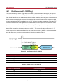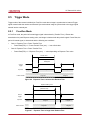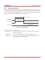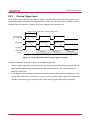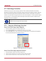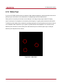
1
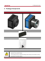
VC Camera Link series Revision History Revision Date 1.0 2010-10-01 Initial release 1.1 2010-12-13 Added “scl” and “gcl” command 1.2 2010-12-21 Added VC-2MC-M/C340 model 1.3 2011-04-07 Revised Max. Frame Rate 1.4 2011-07-12 Added 2 Tap and 4 Tap 10 bit 1.5 2011-10-25 Description Added VC-2MC-150 and VC-4MC-80 Added Camera Block Diagram description Added Data Format Added Defective Pixel Correction Added Appendix A and B 1.6 2011-11-11 Added VC-4MC-40 1.7 2012-06-19 Added 8 Tap 10 bit data output to VC-2MC-340 and VC-4MC-180 models 1.8 2012-08-27 Revised the description of the Get Trigger Mode command 1.9 2012-10-15 Changed the User Manual file name Deleted VC-4MC-40 model Added VC-3MC-280 model Added VC-25MC-30 model Added description of M5 set screws for tilt adjustment Added Actual Time Applied for Commands Added VC-12MC-65 Added 2 Tap and 4 Tap output mode to VC-12MC-65 Revised the maximum FPS values depending on ROI Size of VC-2MC 2.0 2013-06-14 2.1 2013-09-09 2.2 2013-11-11 2.3 2014-07-25 Added the maximum FPS values depending on ROI Size of VC-4MC 2.4 2014-09-19 Applied new CI 2.5 2015-04-30 Added the Flat Field Correction feature to VC-25MC-30 Page 2 of 81 RA14-11A-010 VC Camera Link series Contents 1 Precautions ..................................................................................................................... 6 2 Warranty .......................................................................................................................... 7 3 Compliance & Certifications.......................................................................................... 7 3.1 FCC Declaration .............................................................................................................. 7 3.2 CE : DoC ......................................................................................................................... 7 3.3 KC ................................................................................................................................... 7 4 Package Components .................................................................................................... 8 5 Product Specifications................................................................................................... 9 6 7 8 5.1 Overview ......................................................................................................................... 9 5.2 Specifications ................................................................................................................ 10 5.3 Camera Block Diagram ................................................................................................. 13 5.4 Sensor Information ........................................................................................................ 14 5.5 Mechanical Specification ............................................................................................... 19 Connecting the Camera ............................................................................................... 23 6.1 Mount Plate ................................................................................................................... 23 6.2 Precaution to center the image sensor .......................................................................... 24 6.3 Precaution about blurring compared to the center ......................................................... 24 6.4 Controlling the Camera .................................................................................................. 24 Camera Interface .......................................................................................................... 25 7.1 General Description ....................................................................................................... 25 7.2 Camera Link Connector ................................................................................................. 25 7.3 Power Input Connector .................................................................................................. 29 7.4 Control Connecter ......................................................................................................... 30 7.5 Trigger Input Circuit ....................................................................................................... 31 7.6 Strobe Output Circuit ..................................................................................................... 32 Camera Features .......................................................................................................... 33 8.1 Region Of Interest (ROI) ................................................................................................ 33 8.2 Multi-ROI (VC-12MC Only) ............................................................................................ 36 8.3 Binning (VC-25MC Only) ............................................................................................... 38 8.4 Exposure ....................................................................................................................... 39 8.4.1 Real Exposure (VC-12MC Only) .....................................................................................................40 Page 3 of 81 RA14-11A-010 VC Camera Link series 8.5 8.5.1 Free-Run Mode................................................................................................................................41 8.5.2 External Sync Mode ........................................................................................................................42 8.5.3 Overlap Trigger Input .......................................................................................................................43 8.6 Camera Link Output ...................................................................................................... 44 8.7 Gain and Offset ............................................................................................................. 45 8.8 Defective Pixel Correction ............................................................................................. 46 8.8.1 8.9 8.9.1 Flat Field Correction (VC-12MC/VC-25MC Only) ........................................................... 47 Flat Field Selector (VC-25MC Only) ................................................................................................49 Auto White Balance (VC-12MC Only) ............................................................................ 50 8.11 Temperature Monitor ..................................................................................................... 50 8.12 Status LED .................................................................................................................... 50 8.13 Data Format .................................................................................................................. 51 8.14 Test Image ..................................................................................................................... 52 8.15 Strobe............................................................................................................................ 53 8.15.1 Strobe Output ...........................................................................................................................53 8.15.2 Strobe Polarity .........................................................................................................................53 8.16 Field Upgrade ................................................................................................................ 53 8.17 Dark Image Correction .................................................................................................. 54 8.18 10 Correction Method ...........................................................................................................................46 8.10 8.17.1 9 Trigger Mode ................................................................................................................. 41 Sequence of Dark Image Correction .......................................................................................54 White Pixel .................................................................................................................... 55 Camera Configuration .................................................................................................. 56 9.1 Setup Command ........................................................................................................... 56 9.2 Actual Time Applied for Commands ............................................................................... 58 9.3 Parameter Storage Space ............................................................................................. 59 9.4 Command List ............................................................................................................... 60 Configurator GUI .......................................................................................................... 63 10.1 Camera Scan ................................................................................................................ 63 10.2 Menu ............................................................................................................................. 64 10.2.1 File ...........................................................................................................................................64 10.2.2 Start-Up ....................................................................................................................................65 10.2.3 Tool...........................................................................................................................................66 10.2.4 About ........................................................................................................................................67 Page 4 of 81 RA14-11A-010 VC Camera Link series 10.3 11 Tab ................................................................................................................................ 68 10.3.1 VIEW tab ..................................................................................................................................68 10.3.2 MODE/EXP Tap .......................................................................................................................70 10.3.3 ANALOG Tab ...........................................................................................................................71 10.3.4 FFC Tab ...................................................................................................................................72 Troubleshooting ........................................................................................................... 73 Appendix A Defective Pixel Map Download ................................................................... 74 Appendix B Field Upgrade............................................................................................... 77 B.1 MCU .............................................................................................................................. 77 B.2 FPGA ............................................................................................................................ 80 Page 5 of 81 RA14-11A-010 VC Camera Link series 1 Precautions General Do not drop, disassemble, repair or alter the device. Doing so may damage the camera electronics and cause an electric shock. Do not let children touch the device without supervision. Stop using the device and contact the nearest dealer or manufacturer for technical assistance if liquid such as water, drinks or chemicals gets into the device. Do not touch the device with wet hands. Doing so may cause an electric shock. Do not store the device at a higher temperature. In addition, maintain the ambient temperature in a range of 0℃ to 40℃ during operation. Otherwise the device may be damaged by excessively high temperatures. Installation & Maintenance Do not install in dusty or dirty areas - or near an air conditioner or heater to reduce the risk of damage to the device. Avoid installing and operating in an extreme environment where vibration, heat, humidity, dust, strong magnetic fields, explosive/corrosive mists or gases are present. Do not apply excessive vibration and shock to the device. This may damage the device. Avoid direct exposure to a high intensity light source. This may damage the image sensor. Do not install the device under unstable lighting conditions. Severe lighting change will affect the quality of the image produced by the device. Do not use solvents or thinners to clean the surface of the device. This can damage the surface finish. Power Supply Applying incorrect power can damage the camera. If the voltage applied to the camera is greater or less than the camera’s nominal voltage, the camera may be damaged or operate erratically. Please refer to 5.2 Specifications for the camera’s nominal voltage. ※ Vieworks Co., Ltd. does NOT provide power supplies with the devices. Make sure the power is turned off before connecting the power cord to the camera. Otherwise, damage to the camera may result. Page 6 of 81 RA14-11A-010 VC Camera Link series 2 Warranty For information about the warranty, please contact your local dealer or factory representative. 3 Compliance & Certifications 3.1 FCC Declaration This equipment has been tested and found to comply with the limits for a Class A digital device, pursuant to part 15 of the FCC Rules. These limits are designed to provide reasonable protection against harmful interference when the equipment is operated in a commercial environment. This equipment generates, uses, and can radiate radio frequency energy and, if not installed and used in accordance with the instruction manual, may cause harmful interference to radio communications. Operation of this equipment in a residential area is likely to cause harmful interference in which case the user will be required to correct the interference at own expenses. 3.2 CE : DoC EMC Directive 2004/108/EC. Testing Standard EN 55022:2006+A1:2007, EN 55024:1998+A1:2001+A2:2003 Class A 3.3 KC KCC Statement Type Description Class A This device obtained EMC registration for office use (Class A), and may be (Broadcasting Communication used in places other than home. Sellers and/or users need to take note of Device for Office Use) this. Page 7 of 81 RA14-11A-010 VC Camera Link series 4 Package Components Package Components VC Camera <C-mount> VC Camera <F-mount> Mount Plate (Optional) M5 Set Screws for Tilt Adjustment (Provided only with F-mount camera) You can adjust the tilt using the M5 set screws, however it is not recommended since it is adjusted as factory default settings. If the tilt settings need to be adjusted inevitably, please contact your local dealer or factory representative for technical support. Page 8 of 81 RA14-11A-010 VC Camera Link series 5 Product Specifications 5.1 Overview VC Series is a high speed industrial area scan camera equipped with the latest global shutter CMOS image sensor. With its high reliability and durability, this camera is best suitable for machine vision requiring high-speed continuous shooting. Main features High speed 2/3/4/12/25 megapixel CMOS image sensor Electronic exposure time control (global shutter) Output Pixel Format VC-2MC / 4MC / 12MC / 25MC: 8 / 10 bit VC-3MC: Strobe Output Defective Pixel Correction Camera Link Output Mode 8 bit VC-2MC / 4MC / 12MC: 2 Tap, 4 Tap, 8 Tap, 10 Tap VC-3MC / 25MC: 8 Tap, 10 Tap Gain/Offset Control Test Image LVDS (RS-644) serial communication by Camera Link interface Temperature monitor Field upgrade Dark image correction (Supported only on VC-2MC / 3MC / 4MC / 12MC) Page 9 of 81 RA14-11A-010 VC Camera Link series 5.2 Specifications Specifications for each VC camera model are as follows. VC Series VC-2MC-150 VC-2MC-340 VC-3MC-280 Resolution (H x V) 2048 × 1088 1696 × 1710 Sensor CMOSIS CMV 2000 On Semiconductor LUPA 3000 Sensor Size (㎟) 11.26 × 5.98 (2/3″) 13.57 × 13.68 (1″) Sensor Type High Speed Progressive Scan CMOS Image Sensor 5.5 ㎛ × 5.5 ㎛ Pixel size 8.0 ㎛ × 8.0 ㎛ Interface Camera Link Electronic Shutter Global Shutter Max. Frame Rate Transfer Time Pixel Data Format 2 Tap: 74.4 fps 2 Tap: N/A 4 Tap: 148.5 fps 4 Tap: N/A 8 Tap: N/A 8 Tap: 295.4 fps 8 Tap: 227 fps 10 Tap: N/A 10 Tap: 337.6 fps 10 Tap: 284 fps 2 Tap: 13.44 ㎳ 2 Tap: N/A 4 Tap: 6.73 ㎳ 4 Tap: N/A 8 Tap: N/A 8 Tap: 3.38 ㎳ 8 Tap: 4.41 ㎳ 10 Tap: N/A 10 Tap: 2.96 ㎳ 10 Tap: 3.51 ㎳ 8 bit (2/4 Tap) 10 bit (2/4 Tap) 8 bit (2/4/8/10Tap) 10 bit (2/4/8 Tap) 8 bit (8/10Tap) Camera Link Pixel Clock 85 ㎒ Exposure Time 1/100000 ~ 7 sec (10 ㎲ step) Cable Length < 5 m (Camera Link Cable at 85 ㎒) Black Offset 0 ~ 63 LSB, 64 step Video Gain 0 ~ 12 ㏈, 64 step Trigger Mode Free-Run, Trigger Programmable Exposure Time and Trigger Polarity External Trigger External, 3.3 V ~ 5.0 V Logical level input, Optically isolated Software Trigger Camera Link CC1 Dynamic Range 60 ㏈ Lens Mount C or F-mount Power 10 ~ 14 V DC, Max. 6 W Environmental Operating: 0℃ ~ 40℃, Storage: -40℃ ~ 70℃ Mechanical 68 ㎜ × 68 ㎜ × 54 ㎜, 420g (with F-mount) Configuration SW Configurator Table 5.1 Specifications of VC Series (VC-2MC / VC-3MC) Page 10 of 81 RA14-11A-010 VC Camera Link series VC Series VC-4MC-80 VC-4MC-180 VC-12MC-65 Resolution (H x V) 2048 × 2048 4096 × 3072 Sensor CMOSIS CMV 4000 CMOSIS CMV 12000 Sensor Size (㎟) 11.26 × 11.26 (1″) 22.5 × 16.9 (Diagonal: 28.14 ㎜) Sensor Type High Speed Progressive Scan CMOS Image Sensor Pixel size 5.5 ㎛ × 5.5 ㎛ Interface Camera Link Electronic Shutter Global Shutter Max. Frame Rate Transfer Time Pixel Data Format 2 Tap: 39.6 fps 2 Tap: 13.0 fps 4 Tap: 78.9 fps 4 Tap: 26.0 fps 8 Tap: N/A 8 Tap: 157.1 fps 8 Tap: 51.7 fps 10 Tap: N/A 10 Tap: 179.5 fps 10 Tap: 64.3 fps 2 Tap: 25.3 ㎳ 2 Tap: 76.9 ㎳ 4 Tap: 12.67 ㎳ 4 Tap: 38.5 ㎳ 8 Tap: N/A 8 Tap: 6.37 ㎳ 8 Tap: 19.4 ㎳ 10 Tap: N/A 10 Tap: 5.58 ㎳ 10 Tap: 15.6 ㎳ 8 bit (2/4 Tap) 8 bit (2/4/8/10Tap) 8 bit (2/4/8/10 Tap) 10 bit (2/4 Tap) 10 bit (2/4/8 Tap) 10 bit (2/4/8 Tap) 85 ㎒ Camera Link Pixel Clock Exposure Time 1/100000 ~ 7 sec (10 ㎲ step) 5/100000~7sec (10 ㎲ step) Cable Length < 5 m (Camera Link Cable at 85 ㎒) Black Offset 0 ~ 63 LSB, 64 step Video Gain 0 ~ 12 ㏈, 64 step Trigger Mode Free-Run, Trigger Programmable Exposure Time and Trigger Polarity External Trigger External, 3.3 V ~ 5.0 V Logical level input, Optically isolated Software Trigger Camera Link CC1 Dynamic Range 60 ㏈ Lens Mount Power C or F-mount 10 ~ 14 V DC, Max. 6 W F-mount 10 ~ 14 V DC, Max. 6 W 10 ~ 14 V DC, Max. 6 W Environmental Operating: 0℃ ~ 40℃, Storage: -40℃ ~ 70℃ Mechanical 68 ㎜ × 68 ㎜ × 54 ㎜, 420g (with F-mount) Configuration SW Configurator Table 5.2 Specifications of VC Series (VC-4MC / VC-12MC) Page 11 of 81 RA14-11A-010 VC Camera Link series VC Series VC-25MC-30 Resolution (H x V) 5120 × 5120 Sensor On Semiconductor VITA-25K Sensor Size (㎟) 23.04 × 23.04 (Diagonal: 32.5 ㎜) Sensor Type High Speed Progressive Scan CMOS Image Sensor Pixel size 4.5 ㎛ × 4.5 ㎛ Interface Camera Link Electronic Shutter Global Shutter 2 Tap: N/A 4 Tap: N/A Max. Frame Rate 8 Tap: 25.3 fps 10 Tap: 30.8 fps 2 Tap: N/A 4 Tap: N/A Transfer Time 8 Tap: 39.42 ㎳ 10 Tap: 32.47 ㎳ Pixel Data Format 8 bit (8/10 Tap), 10 bit (8 Tap) Camera Link Pixel Clock 85 ㎒ Exposure Time 1/100000 ~ 7 sec (10 ㎲ step) Cable Length < 5 m (Camera Link Cable at 85 ㎒) Black Offset 0 ~ 63 LSB, 64 step Video Gain 0 ~ 12 ㏈, 64 step Trigger Mode Free-Run, Trigger Programmable Exposure Time and Trigger Polarity External Trigger External, 3.3 V ~ 5.0 V Logical level input, Optically isolated Software Trigger Camera Link CC1 Dynamic Range 54 ㏈ Lens Mount F-mount Power 10 ~ 14 V DC, Max. 8 W Environmental Operating: 0℃ ~ 40℃, Storage: -40℃ ~ 70℃ Mechanical 68 ㎜ × 68 ㎜ × 54 ㎜, 420g (with F-mount) Configuration SW Configurator Table 5.3 Specifications of VC Series (VC-25MC) Page 12 of 81 RA14-11A-010 VC Camera Link series 5.3 Camera Block Diagram DDR2 Ext. Trig FPGA 16 / 32 Channel LVDS Image Data CMOS Sensor SPI Control Image Processing And Control Logic FLASH CameraLink Full Configuration MicroController EEPROM Strobe SRAM Figure 5.1 Camera Block Diagram All controls and data processing of VC cameras are carried out in one FPGA chip. The FPGA generally consists of a 32 bit RICS Micro-Controller and Processing & Control Logic. The Micro-Controller receives commands from the user through the Camera Link interface and then processes them. The Processing & Control Logic processes the image data received from the CMOS sensor and then transmits data through the Camera Link interface. And also, the Processing & Control Logic controls the trigger inputs and strobe outputs which are sensitive to time. Furthermore, FLASH and DDR2 is installed outside FPGA. DDR2 is used to process images and FLASH contains the firmware that operates the Micro-Controller. Page 13 of 81 RA14-11A-010 VC Camera Link series 5.4 Sensor Information The following graphs show the spectral response for VC-2MC monochrome and color camera. Figure 5.2 Mono Spectral Response for VC-2MC Figure 5.3 Color Spectral Response for VC-2MC Page 14 of 81 RA14-11A-010 VC Camera Link series The following graph shows the spectral response for VC-3MC monochrome and color camera. Figure 5.4 Mono and Color Spectral Response for VC-3MC Page 15 of 81 RA14-11A-010 VC Camera Link series The following graphs show the spectral response for VC-4MC monochrome and color camera. Figure 5.5 Mono Spectral Response for VC-4MC Figure 5.6 Color Spectral Response for VC-4MC Page 16 of 81 RA14-11A-010 VC Camera Link series The following graph shows the spectral response for VC-12MC monochrome and color camera. Figure 5.7 Mono and Color Spectral Response for VC-12MC Page 17 of 81 RA14-11A-010 VC Camera Link series The following graph shows the spectral response for VC-25MC monochrome and color camera. Figure 5.8 Mono and Color Spectral Response for VC-25MC Page 18 of 81 RA14-11A-010 VC Camera Link series 5.5 Mechanical Specification The camera dimensions in millimeters are as shown in the following figures. Figure 5.9 VC-2MC / 3MC / 4MC Camera Link C-mount Mechanical Dimension Page 19 of 81 RA14-11A-010 VC Camera Link series Figure 5.10 VC-2MC / 3MC / 4MC Camera Link F-mount Mechanical Dimension Page 20 of 81 RA14-11A-010 VC Camera Link series Figure 5.11 VC-12MC Camera Link F-mount Mechanical Dimension Page 21 of 81 RA14-11A-010 VC Camera Link series Figure 5.12 VC-25MC Camera Link F-mount Mechanical Dimension Page 22 of 81 RA14-11A-010 VC Camera Link series 6 Connecting the Camera The following instructions assume that you have installed a Camera Link frame grabber in your PC including related software. For more information, refer to your Camera Link frame grabber User Manual. To connect the camera to your PC, follow the steps below: 1 Make sure that the power supply is not connected to the camera and your PC is turned off. 2 Plug one end of a Camera Link cable into the Camera Link connector on the camera and the other end of the Camera Link cable into the connector on your Camera Link frame grabber. 3 Connect the plug of the power adaptor to the power input connector on the camera. 4 Plug the power adaptor into a working electrical outlet. 5 Verify that all the cable connections are secure. 6.1 Mount Plate The Mount Plate is provided as an optional item. The camera can be fixed without using this Mount Plate. Page 23 of 81 RA14-11A-010 VC Camera Link series 6.2 Precaution to center the image sensor User does not need to center the image sensor as it is adjusted as factory default settings. When you need to adjust the center of image sensor, please contact your local dealer or the manufacturer for technical assistance. 6.3 Precaution about blurring compared to the center User does not need to adjust the tilt as it is adjusted as factory default settings. If the tilt settings need to be adjusted inevitably, please contact your local dealer or factory representative for technical support. 6.4 Controlling the Camera You can control the camera by executing the Configurator.exe file. You can download the latest Configurator at machinevision.vieworks.com. Please refer to your Camera Link frame grabber user manual. Page 24 of 81 RA14-11A-010 VC Camera Link series 7 Camera Interface 7.1 General Description As shown in the following figure, 4 types of connectors and status indicator LED are located on the back of the camera and have the functions as follows: ① 26 pin Camera Link Connector 1 (Base): ② 26 pin Camera Link Connector 2 (Medium/Full): transmits video data ③ Status LED: displays power status and operation mode. ④ 6 pin Power Input Connector: supplies power to the camera. ⑤ 4 pin Control Connector: inputs external trigger signal and outputs strobe. controls video data transmission and the camera. ① ② ③ ④ ⑤ Figure 7.1 VC Series Back Panel 7.2 Camera Link Connector CAMERA LINK 1 13 1 26 14 Figure 7.2 Camera Link Connector Page 25 of 81 RA14-11A-010 VC Camera Link series Camera output complies with Camera Link Standard and the following list shows the pin configuration of the connector. PAIR List Pin Signal Name Type Description 1 Ground Ground Cable Shield 14 Ground Ground Cable Shield 2 -X0 LVDS - Out Camera Link Transmitter 15 +X0 LVDS - Out Camera Link Transmitter 3 -X1 LVDS - Out Camera Link Transmitter 16 +X1 LVDS - Out Camera Link Transmitter 4 -X2 LVDS - Out Camera Link Transmitter 17 +X2 LVDS - Out Camera Link Transmitter 5 -XCLK LVDS - Out Camera Link Transmitter 18 -XCLK LVDS - Out Camera Link Transmitter 6 -X3 LVDS - Out Camera Link Transmitter 19 +X3 LVDS - Out Camera Link Transmitter 7 + SerTC LVDS - In Serial Data Receiver 20 - SerTC LVDS - In Serial Data Receiver 8 - SerTFG LVDS - Out Serial Data Transmitter 21 + SerTFG LVDS - Out Serial Data Transmitter 9 - CC 1 LVDS - In Software External Trigger 22 + CC 1 LVDS - In Software External Trigger 10 N/C N/C N/C 23 N/C N/C N/C 11 N/C N/C N/C 24 N/C N/C N/C 12 N/C N/C N/C 25 N/C N/C N/C 13 Ground Ground Cable Shield 26 Ground Ground Cable Shield PAIR 0 PAIR 1 PAIR 2 PAIR 3 PAIR 4 PAIR 5 PAIR 6 PAIR 7 PAIR 8 PAIR 9 PAIR 10 PAIR 11 PAIR 12 Table 7.1 Pin Assignments for Camera Link Connector 1 Page 26 of 81 RA14-11A-010 VC Camera Link series PAIR List Pin Signal Name Type Description 1 Ground Ground Cable Shield 14 Ground Ground Cable Shield 2 -Y0 LVDS - Out Camera Link Transmitter 15 +Y0 LVDS - Out Camera Link Transmitter 3 -Y1 LVDS - Out Camera Link Transmitter 16 +Y1 LVDS - Out Camera Link Transmitter 4 -Y2 LVDS - Out Camera Link Transmitter 17 +Y2 LVDS - Out Camera Link Transmitter 5 -YCLK LVDS - Out Camera Link Transmitter 18 +YCLK LVDS - Out Camera Link Clock Tx 6 -Y3 LVDS - Out Camera Link Channel Tx 19 +Y3 LVDS - Out Camera Link Channel Tx 7 - Not Used 20 - Not Used 8 -Z0 LVDS - Out Camera Link Transmitter 21 +Z0 LVDS - Out Camera Link Transmitter 9 -Z1 LVDS - Out Camera Link Transmitter 22 +Z1 LVDS - Out Camera Link Transmitter 10 -Z2 LVDS - Out Camera Link Transmitter 23 +Z2 LVDS - Out Camera Link Transmitter 11 -ZCLK LVDS - Out Camera Link Transmitter 24 +ZCLK LVDS - Out Camera Link Clock Tx 12 -Z3 LVDS - Out Camera Link Channel Tx 25 +Z3 LVDS - Out Camera Link Channel Tx 13 Ground Ground Cable Shield 26 Ground Ground Cable Shield PAIR 0 PAIR 1 PAIR 2 PAIR 3 PAIR 4 PAIR 5 PAIR 6 Connected with 100 ohm PAIR 7 PAIR 8 PAIR 9 PAIR 10 PAIR 11 PAIR 12 Table 7.2 Pin Assignments for Camera Link Connector 2 Page 27 of 81 RA14-11A-010 VC Camera Link series Model Camera Link Output Mode CL Configuration CL Connector 1 CL Connector 2 2 Tap BASE O X 4 Tap MEDIUM O O 8 Tap FULL O O 10 Tap FULL O O VC-3MC-280 8 Tap FULL O O VC-25MC-30 10 Tap FULL O O VC-2MC-340 VC–4MC-180 VC-12MC-65 Table 7.3 Connector Arrangement for Camera Link Output Modes When you connect a Frame Grabber to Camera Link Connectors using Camera Link cables, make sure you connect to the correct Camera Link Connector. Incorrect connection of Connector 1 and Connector 2 may cause malfunction of the camera or communication problems between PC and the camera. Page 28 of 81 RA14-11A-010 VC Camera Link series 7.3 Power Input Connector The power input connector is a Hirose 6 pin connector (part # HR10A-7R-6PB). Pin arrangement and configuration are as follows: 1 6 3 4 2 5 Figure 7.3 Pin Arrangement of Power Input Connector Pin Number Signal Type Description 1, 2 , 3 + 12V DC Input DC Power Input 4,5,6 DC Ground Input DC Ground Table 7.4 Pin Configuration of Power Input Connector Connecting the power cable to the camera can be made by using the Hirose 6 pin plug (part # HR10A-7P-6S) or the equivalent. The power adaptor is recommended to have at least 1A current output at 12 V DC ±10% voltage output (Users need to purchase the power adaptor separately). Precaution for Power Input Make sure the power is turned off before connecting the power cord to the camera. Otherwise, damage to the camera may result. If the camera input voltage is greater than 16 V, damage to the camera may result. Page 29 of 81 RA14-11A-010 VC Camera Link series 7.4 Control Connecter The control connector is a Hirose 4 pin connector (part # HR10A-7R-4S) and consists of an external trigger signal input and strobe output port. Pin arrangement and configuration are as follows: 4 1 3 2 Figure 7.4 Pin Arrangement of Control Connector Pin Number Signal Type Description 1 Trigger Input + Input - 2 Trigger Input - Input - 3 DC Ground - DC Ground 4 Strobe Out Output 3.3 V TTL Output Output resistance : 47 Ω Table 7.5 Pin Arrangement of Control Connector The mating connector is a Hirose 4 pin plug (part # HR10A-7P-4P) or the equivalent connectors. Page 30 of 81 RA14-11A-010 VC Camera Link series 7.5 Trigger Input Circuit Following figure shows trigger signal input circuit of the 4-pin connector. Transmitted trigger signal is applied to the internal circuit through a photo coupler. Minimum trigger width that can be recognized by the camera is 1 ㎲. If transmitted trigger signal is less than 1 ㎲, the camera will ignore the trigger signal. External trigger circuit example is shown below. +5V 1 kΩ STROBE_OUT + 4 1 TRIGGER_IN+ 3 2 TRIGGER_IN- 330 Ω TRIGGER_IN PHOTO COUPLER HR10A-7R-4SB Figure 7.5 Trigger Input Schematic Output Resistance < 100 Ω TRIGGER_IN + : Pin 1 Pulse Width > 1us Amplitude Range : 3 V ~ 5 V TRIGGER_IN - : PIN 2 Figure 7.6 Recommended Pulse Trigger Driver Input ON Resistance < 100 Ω TRIGGER_IN - : Pin 2 Minimum ON Time > 1us GROUND : PIN 3 Figure 7.7 Recommended Contact Trigger Input Page 31 of 81 RA14-11A-010 VC Camera Link series 7.6 Strobe Output Circuit The strobe output signal is 3.3 V output level of a TTL Driver IC. The pulse width of signal is synchronized with the exposure signal (shutter) of the camera. +3.3V 3.3 V 3.3 V 0 V 47 Ω STROBE_SIGNAL TTL Driv er STROBE_OUT 4 1 TRIGGER_IN + 3 2 TRIGGER_IN - HR10A-7R-4SB Figure 7.8 Strobe Output Schematic Page 32 of 81 RA14-11A-010 VC Camera Link series 8 8.1 Camera Features Region Of Interest (ROI) The Region of Interest (ROI) feature allows you to specify a portion of the sensor array. You can acquire only the frame data from the specified portion of the sensor array while preserving the same quality as you acquire a frame from the entire sensor array. ROI is determined as the overlapping area of two areas when designating start point and end point in horizontal and vertical direction as shown in the figure below. Start point and End point mean the starting and end of the ROI. In the VC-2MC, 4MC and 12MC models, the frame rate will increase as the vertical ROI is made smaller. However, the horizontal ROI does not affect the frame rate. In the VC-3MC and VC-25MC models, the frame rate will increase as both the vertical and horizontal ROI are made smaller. (0, 0) (HSIZE - 1, 0) Horizontal ROI V Start Region Of Vertical Interest ROI V End (HSIZE - 1, VSIZE - 1) (0, VSIZE - 1) H Start H End Figure 8.1 ROI In VC-2MC, the maximum frame rates depending on the changes of vertical ROI are shown in the following table. ROI Size (H × V) 2 Tap 4 Tap 8 Tap 10 Tap 2048 × 16 3689.3 fps 6692.2 fps 10622.3 fps 12103.0 fps 2048 × 32 2094.4 fps 4036.9 fps 6979.1 fps 7960.3 fps 2048 × 64 1123.3 fps 2250.8 fps 4139.6 fps 4725.4 fps 2048 × 128 582.8 fps 1194.1 fps 2282.4 fps 2606.7 fps 2048 × 256 297.0 fps 615.9 fps 1203.0 fps 1374.3 fps 2048 × 512 149.9 fps 312.9 fps 618.2 fps 706.4 fps 2048 × 1024 75.3 fps 157.7 fps 313.5 fps 358.2 fps Table 8.1 VC-2MC Maximum Frame Rate depending on ROI Size Page 33 of 81 RA14-11A-010 VC Camera Link series In VC-3MC, the maximum frame rates depending on the changes of both horizontal and vertical ROI are shown in the following table. ROI Size (H × V) 8 Tap 10 Tap 640 × 480 1830 fps 2288 fps 1024 × 768 807 fps 1010 fps 1280 × 1024 486 fps 632 fps 1600 × 1200 346 fps 432 fps 1680 × 1680 229 fps 296 fps 1696 × 1710 227 fps 284 fps Table 8.2 VC-3MC Maximum Frame Rate depending on ROI Size In VC-4MC, the maximum frame rates depending on the changes of vertical ROI are shown in the following table. ROI Size (H × V) 2 Tap 4 Tap 8 Tap 10 Tap 2048 × 16 3689.3 fps 6692.2 fps 10622.3 fps 12103.0 fps 2048 × 32 2094.4 fps 4036.9 fps 6979.1 fps 7960.3 fps 2048 × 64 1123.3 fps 2250.8 fps 4139.6 fps 4725.4 fps 2048 × 128 582.8 fps 1194.1 fps 2282.4 fps 2606.7 fps 2048 × 256 297.0 fps 615.9 fps 1203.0 fps 1374.3 fps 2048 × 512 149.9 fps 312.9 fps 618.2 fps 706.4 fps 2048 × 1024 75.3 fps 157.7 fps 313.5 fps 358.2 fps 2048 × 2048 39.6 fps 78.9 fps 157.1 fps 179.5 fps Table 8.3 VC-4MC Maximum Frame Rate depending on ROI Size In VC-12MC, the maximum frame rates depending on the changes of vertical ROI are shown in the following table. ROI Size (H × V) 2 Tap 4 Tap 8 Tap 10 Tap 4096 × 500 78 fps 156 fps 304.1 fps 377.9 fps 4096 × 1000 39 fps 79 fps 155.8 fps 193.6 fps 4096 × 1500 26 fps 52 fps 104.7 fps 130.1 fps 4096 × 2000 19 fps 39 fps 78.9 fps 98.0 fps 4096 × 2500 15 fps 31 fps 63.2 fps 78.6 fps 4096 × 3072 13 fps 25 fps 51.6 fps 64.0 fps Table 8.4 VC-12MC Maximum Frame Rate depending on ROI Size Page 34 of 81 RA14-11A-010 VC Camera Link series In VC-25MC, the maximum frame rates depending on the changes of both horizontal and vertical AOI are shown in the following table. AOI Size (H × V) 8 Tap 10 Tap 3000 × 3000 57.0 fps 69.2 fps 4000 × 3000 49.3 fps 59.9 fps 4000 × 4000 37.0 fps 45.0 fps 5120 × 5120 25.3 fps 30.8 fps Table 8.5 VC-25MC Maximum Frame Rate depending on ROI Size The ROI values (H × V) may vary depending on the type of Camera Link frame grabber. For technical assistance, contact your local dealer or the manufacturer. The ROI setting commands for VC-12MC are different from the other models since it supports the Multiple ROI feature. Refer to Table 9.4 Command List #4 for the related commands. Page 35 of 81 RA14-11A-010 VC Camera Link series 8.2 Multi-ROI (VC-12MC Only) The VC-12MC-65 model provides the Multi-ROI feature which allows you to define up to thirty two regions on the sensor array. When an image is acquired, only the pixel information from the defined regions will be readout of the sensor. The pixel data read out of the regions will then be combined together and will be transmitted from the camera as a single image. It is recommended that you first set the Offset X and Width parameters, since all of the regions must be the same width and all of the regions must be vertically aligned. The next step in the setup process is to define each individual region in order. Up to 32 regions can be set up ranging from 0 through 31. Set the each region to ON/OFF and then set the Offset Y (the offset between the top of the sensor and the top of the region) and Height (the height of the region) values to define each region. In figure 8.2, for example, three regions have been set. With these settings, the camera would output an image with 2048 (width) × 1844 (the total height of the three regions) size. Offset X = 1024, Width = 2048 ROI_0 ROI_1 Offset Y = 204, Height = 512 Offset Y = 1024, Height = 716 ROI_2 Offset Y = 2356, Height =616 Figure 8.2 Multi-ROI Page 36 of 81 RA14-11A-010 VC Camera Link series There are several things to keep in mind when setting Multi-ROI: The sum of the Offset X value plus the Width value must not exceed the width (4096 on the VC-12MC) of the camera’s sensor. The sum of the Offset Y value plus the Height value must not exceed the height (3072 on the VC-12MC) of the camera’s sensor. The Offset X and Width values must be a multiple of 8 ranging from 24 to 4096. The Offset Y and Height values must be a multiple of 4 ranging from 4 to 3072. You need to set the regions in order. When you set a preceding region to OFF, all the succeeding regions will be set to OFF automatically. For example, you have set four regions from 0 through 4. If you set the region 1 to OFF, the region 2, 3 and 4 will be set to OFF. You do not need to order the regions from top to bottom on the sensor. For example, you could place the region 1 near the bottom of the sensor, the region 2 near the top, and the region 3 in the middle. You can save (Configurator > File > Save Setting > User 1 or User 2) the setting values for Multi-ROI to parameter storage space and then load (Configurator > File > Load Setting > From User 1 Space or From User 2 Space) the values to the camera when desired. Refer to Table 9.4 Command List #4 for the commands related to Multi-ROI. Page 37 of 81 RA14-11A-010 VC Camera Link series 8.3 Binning (VC-25MC Only) Binning has the effects of increasing the level value and decreasing resolution by adding the values of the adjacent pixels and sending them as one pixel. VC-25MC provides two binning factor (×1 and ×2) that the user can apply both horizontally and vertically. The below figure shows application of 2 × 2 binning, four pixels are summed and reported out of the camera as a single pixel. Using binning reduces the resolution of camera’s imaging sensor in half, however, it results in double signal to noise ratio with the same brightness as an original image. You can set the Binning Factor by using the “sbf” command. Figure 8.3 2 × 2 Binning Even if the binning is performed on the color camera, the resulting image will be monochrome. Page 38 of 81 RA14-11A-010 VC Camera Link series 8.4 Exposure The CMOS sensor of VC series uses global shutter that exposes the entire imager simultaneously. The below figure illustrates the timing of exposure and readout of CMOS sensor. Readout is performed consecutively from first to last line where readout defines the process of reading the accumulated charges on pixels. Readout Time (also called Transfer Time) defines the rate at which one frame of an image is transferred. Start of exposure End of exposure Trigger Signal Input Image Readout Readout Time Figure 8.4 Exposure Timing Diagram Page 39 of 81 RA14-11A-010 VC Camera Link series 8.4.1 Real Exposure (VC-12MC Only) In VC-12MC-65, when you set the Trigger Mode to Free-Run or the Exposure Mode to Program, the exposure time will be determined by the user settings (“set” command). With these settings, the camera will generate trigger signals internally. As soon as the camera detects a trigger signal, the camera will begin a frame exposure. When the exposure time ends, the pixels are being sampled and prepared for readout. This sequence is called the frame overhead time (FOT). Immediately after the FOT, the frame is read out automatically. During the FOT, an additional exposure time will be applied as the offset value shown in the Figure 8.5. This offset value varies depending on the camera’s Camera Link Output Mode settings. The setting value on the exposure time is equal to actual exposure time, because the offset value is compensated on the actual exposure time. In 8 tap output channel mode, for example, the exposure time is set to 200 ㎲. The camera will subtract offset value 50 ㎲ from the exposure time setting internally, and thus the actual exposure time will be 200 ㎲ as the user settings. Due to the offset value, the minimum exposure time is limited as shown in the Table 8.6. Figure 8.5 Real Exposure for VC-12MC-65 Camera Link Output Mode Offset Value 2 Tap 50 ㎲ 4 Tap 50 ㎲ 8 Tap 50 ㎲ 10 Tap 40 ㎲ Table 8.6 Offset Value for VC-12MC-65 Camera Link Output Mode Minimum Exposure Time 2 Tap 50 ㎲ 4 Tap 50 ㎲ 8 Tap 50 ㎲ 10 Tap 40 ㎲ Table 8.7 Minimum Exposure Time for VC-12MC-65 Page 40 of 81 RA14-11A-010 VC Camera Link series 8.5 Trigger Mode Trigger mode of the camera is divided into Free-Run mode where image is synchronized to Internal Trigger signal created inside the camera and External Sync mode where image is synchronized to the trigger signal entered into the external port. 8.5.1 Free-Run Mode In Free-Run mode, the period of internal trigger signal is determined by Transfer Time (1 Frame data transmission time) and Exposure setting value, and image is obtained with this periodic signal. Frame Rate, the period of internal signal, is determined with the following two conditions. Case 1: Exposure Time < Frame Transfer Time Frame Rate(FPS) = 1 / Frame Transfer Time (sec) → has a fixed value. Case 2: Exposure Time > Frame Transfer Time Frame Rate(FPS) = 1 / Exposure Time (sec) → varies depending on Exposure Time value. Transfer Time Exposure SettingTime Internal Trigger Exposure Image N-1 Image N Image N-1 Frame Transfer Image N + 1 Image N Figure 8.6 Exposure Time is shorter than Readout Time Exposure Setting Time Transfer Time (Readout Time) Internal Trigger Exposure Frame Transfer Image N-1 Image N Image N-1 Image N + 1 Image N Figure 8.7 Exposure Time is longer than Readout Time Page 41 of 81 RA14-11A-010 VC Camera Link series 8.5.2 External Sync Mode In External Sync Mode, camera keeps standby status until trigger signal is entered, and when trigger is entered, the image is transmitted (frame transfer) after exposure process. To operate the camera in External Sync mode, it is required to set Trigger Source regarding which input, CC1 input port or External Trigger port, will be used for trigger signal, as well as Polarity and Exposure source of the signal entered. Trigger Pulse Width External Trigger (CC1 or External) EXPOSURE Exposure Time Transfer Time Data Transfer Figure 8.8 External Sync Mode Following is the summary of basic setting items. Trigger Source: select either CC1 (Camera Control Port 1) or External Connector as source of the external trigger input signal. Trigger Polarity: set whether polarity of Trigger signal entered is Active High or Active Low. Exposure Source: select to synchronize exposure time with pulse width of trigger input signal or with exposure time programmed inside the camera. Page 42 of 81 RA14-11A-010 VC Camera Link series 8.5.3 Overlap Trigger Input When trigger is entered during frame transfer as shown in the figure below, it performs exposure process for newly entered trigger while transferring the previous data. In this case, shooting images is possible up to the maximum frame rate (speed of 1/Transfer Time (sec)) regardless of the exposure time. Exposure Source (Pulse width / Program exposure time ) External Trigger (CC1 or External) Exposure N EXPOSURE Exposure N+1 Exposure N+2 Strobe Out Data Transfer (FVAL) Image N Image N+1 Image N+2 Figure 8.9 Camera Operation when Overlap Trigger is entered Following list shows the operation of camera on exceptional trigger input. When the trigger signal with the faster period than the maximum frame rate condition is entered, the next frame transfer is performed before completing the previous frame transfer. This causes the failure of obtaining overall image. If new trigger is entered during the exposure process after Exposure Source is set as Program, the newly entered signal will be ignored. In this case, exposure time is longer than trigger input period and the frame rate will be slower than trigger input period since all the entered trigger signals cannot synchronize. Page 43 of 81 RA14-11A-010 VC Camera Link series 8.6 Camera Link Output † VC Series supports 2 Tap, 4 Tap, 8 Tap or 10 Tap output modes according to the user interface. Tap setting value defines the number of output pixel data for each Pixel Clock Cycle (85 ㎒), and the speed of frame data transmission varies depending on the tap setting. Frame Data is output in interleaved order as shown in the figure below. This tap setting can be set using the “scl” command. A B A B 2 Tap Output (BASE *1) 1 Pixel Clock Cycle A B C D A B 4 Tap Output (MEDIUM *1) 1 Pixel Clock Cycle A B C D E F G H A B 1 Pixel Clock Cycle A B C D E F G H AI J B A B 8 Tap Output (FULL *1) 10 Tap Output (FULL *1) 1 Pixel Clock Cycle *1 : Camera-Link Configuration Figure 8.10 Camera Link Output Mode † Supported Camera Link Output Mode VC-2MC-150 and VC-4MC-80 support 2 Tap and 4 Tap. VC-2MC-340, VC-4MC-180 and VC-12MC-65 support 2 Tap, 4 Tap, 8 Tap and 10 Tap. VC-3MC-280 and VC-25MC-30 support 8 Tap and 10 Tap. Page 44 of 81 RA14-11A-010 VC Camera Link series 8.7 Gain and Offset Gain and Offset can be changed through Voltage Reference adjustment which is applied commonly to all ADCs. Gain adjustment can be set among 0 ~ 12 ㏈ and setting value can be set as a value from 0 to 64 step. Relation between setting value and actual Gain (㏈) is shown below: Gain(㏈) = (setting value) × 0.19 ㏈ Figure 8.11 Register Setting vs Gain Offset can be set between 0 ~ 63 (LSB) based on 8 bit data output and setting value has 64 step values. Page 45 of 81 RA14-11A-010 VC Camera Link series 8.8 Defective Pixel Correction The CMOS sensor may have Defect Pixels which cannot properly react to the light. Correction is required since it may deteriorate the quality of output image. Defect Pixel information of CMOS used for each camera is entered into the camera during the manufacturing process. If you want to add Defect Pixel information, it is required to enter coordinate of new Defect Pixel into the camera. For more information, refer to Appendix A. The “sdc” command is used to set whether to use Defective Pixel Correction feature. 8.8.1 Correction Method Correction value for Defect Pixel is calculated based on valid pixel value adjacent in the same line. L3 L2 L1 R1 R2 R3 <Current Pixel> Figure 8.12 Location of Defect Pixel to be corrected If Current Pixel is a Defect Pixel as shown in the above figure, correction value of this pixel is obtained as shown in the following table depending on whether surrounding pixel is Defect Pixel or not. Adjacent Defect Pixel(s) Correction value of Current Pixel None (L1 + R1) / 2 L1 R1 R1 L1 L1, R1 (L2 + R2 ) / 2 L1, R1, R2 L2 L2, L1, R1 R2 L2, L1, R1, R2 (L3 + R3) / 2 L2, L1, R1, R2, R3 L3 L3, L2, L1, R1, R2 R3 Table 8.8 Calculation of Defect Pixel Correction Value Page 46 of 81 RA14-11A-010 VC Camera Link series 8.9 Flat Field Correction (VC-12MC/VC-25MC Only) The Flat Field Correction feature improves the image uniformity when you acquire a non-uniformity image due to external conditions. The Flat Field Correction feature can be summarized by the following equation: IC = (IR – IB) / (IF – IB) Where, IC : Level value of corrected image; IR : Level value of original image; IB : Black offset value; IF : Level value of Flat Field data. In order to use the Flat Field Correction feature, one must first generate IF, the Flat Field data. This can be done by adjusting the camera to the actual environment and activating the Flat Field Generator. The Flat Field Generator will standardize a series of images, curtailing the image to 1/16 pixel, generate the curtailed Flat Field data, and store it in the internal frame buffer of the FPGA. When curtailed images are used for corrections, it is expanded and applied with a Bilinear Interpolation as shown in the Figure 8.14. Use “gfd” command to generate the Flat Field data and use the “sfc” command to apply the Flat Field Correction. At this time, the Flat Field data is stored on the RAM, a volatile memory. In order to reuse the stored data, use “sdf” command to store them on the FLASH, a non-volatile memory. 1. It is recommended that you enable the Defective Pixel Correction feature before activating the Flat Field Generator. 2. Activating the Flat Field Generator will set the camera’s resolution to its full resolution. 3. To acquire an image, operate the camera with free-run mode or apply a trigger signal. 4. When the generation of the Flat Field data is completed, the previous settings for the camera will be restored. Page 47 of 81 RA14-11A-010 VC Camera Link series <Flat Field Calibration Block Diagram> 1/64 Scale Down External SRAM <Flat Fielding Block Diagram> Bilinear Interpolated Magnification External SRAM <IF> IR*M/IF <IR> <IC> Figure 8.13 Generation and Application of Flat Field Data 16 Pixel Magnified Image Boundary 16 Pixel Scale-Down Data Magnified Image Boundary Figure 8.14 Bilinear Interpolated Magnification Page 48 of 81 RA14-11A-010 VC Camera Link series 8.9.1 Flat Field Selector (VC-25MC Only) As mentioned above, the active Flat Field data is stored in the camera’s volatile memory and the data is lost if the camera is reset of powered off. To use the active or generated Flat Field data after the camera is powered on or reset, you need to save them in the camera’s non-volatile memory. The VC-25MC model provides four reserved areas in the camera’s non-volatile memory available for saving Flat Field data. You can use the Flat Field Selector feature to select one of the four reserved areas. Figure 8.15 Flat Field Selector Saving a Flat Field data To save the current active Flat Field data into a reserved area in the camera’s flash memory, 1. Use the “sfs 0/1/2/3” command to specify a reserved area where the current active Flat Field data will be stored. 2. Use the “sfd” command or click the Save to Flash button in Configurator to save the active Flat Field data to the selected reserved area. Loading the Flat Field data If you saved a Flat Field data into the camera’s non-volatile memory, you can load the saved Flat Field data from the camera’s non-volatile memory into the camera’s active Flat Field data. 1. Use the “sfs 0/1/2/3” command to specify a reserved area whose Flat Field data will be loaded into the camera’s active Flat Field data. 2. Use the “lfd” command or click the Load from Flash button to load the selected Flat Field data into the active Flat Field data. Page 49 of 81 RA14-11A-010 VC Camera Link series 8.10 Auto White Balance (VC-12MC Only) The Auto White Balance feature is implemented on the VC-12MC-C65 color camera. It will control the white balance of the image acquired from the color camera according to the GreyWorld algorithm. The entire pixel data will be used by the Auto White Balance feature to control the white balance. As soon as you activate the Auto White Balance feature, the Digital Red, Digital Green and Digital Blue will be set to 1. Then the Digital Red and Digital Blue will be adjusted to control the white balance. The “arg” command is used to set whether to use the Auto White Balance feature. 8.11 Temperature Monitor The camera has an embedded sensor chip to monitor the internal temperature. The “gct” command is used to check the temperature of the camera. 8.12 Status LED There is a green LED to inform the operation status on the back of camera. LED status and corresponding camera status are as follows: Continuous ON: operates in Free-Run Mode. Repeat ON for 0.5 second, OFF for 0.5 second: operates in Trigger Mode. Repeat ON for 1 second, OFF for 1 second: outputs Test Image. Repeat ON for 0.25 second, OFF for 0.25 second: operates in Trigger Mode and outputs Test Image. Page 50 of 81 RA14-11A-010 VC Camera Link series 8.13 Data Format † Data can be processed in the unit of 10 bit internally, but can be selectively output in the unit of 8 or 10 bit at output. When it is output in 8 bit unit, the 2 least significant bits will be dropped from overall 10 bits. LSB MSB Original Data D9 D8 D7 D6 D5 D4 D3 D2 D1 D0 10Bit Output D9 D8 D7 D6 D5 D4 D3 D2 D1 D0 8Bit Output D7 D6 D5 D4 D3 D2 D1 D0 Figure 8.16 Data Format † Supported data format VC-3MC-280 supports only 8 bit. Page 51 of 81 RA14-11A-010 VC Camera Link series 8.14 Test Image To check normal operation of the camera, it can be set to output test image created inside, instead of image data from the imaging sensor. There are 3 types of test image; image with different value in horizontal direction (Test Image 1), image with different value in diagonal direction (Test Image 2), and moving image with different value in diagonal direction (Test Image 3). Test image can be applied in all operation modes of the camera. To set Test Image, use the “sti” command. Figure 8.17 Test Image 1 Figure 8.18 Test Image 2 Figure 8.19 Test Image 3 Page 52 of 81 RA14-11A-010 VC Camera Link series 8.15 Strobe Strobe signal is used to synchronize the external light source with camera or to measure the exposure time applied to current camera. Pulse width of Strobe signal is from the generating point of Shutter signal to the starting point of Readout, which coincides with exposure time of camera. 8.15.1 Strobe Output The camera can provide the Strobe Output signal that is synchronized with the exposure time of the camera. The Strobe Output signal is shown below. Pulse Width Internal or External Trigger Exposure Exposure Time Strobe Out (Active High) Strobe Figure 8.20 Strobe signal in Trigger mode 8.15.2 Strobe Polarity Polarity can be set for Strobe signal output. The “ssp" command is used to set the polarity of strobe signal. 8.16 Field Upgrade The camera has the function to upgrade firmware and FGPA logic through RS-644 interface of Camera Link, rather than disassemble the camera in the field. See Appendix B for details on how to upgrade. Page 53 of 81 RA14-11A-010 VC Camera Link series 8.17 Dark Image Correction CMOS sensor may result in lower sensitivity at dark level. This is caused by fixed pattern noise variation depending on the exposure settings or characteristic change according to the temperature variation of AFE and sensor cell. Sensitivity change resulted by temperature variation is less than 1 ㏈/10 degree. The acquisition condition of correction data is 25 degree based on the camera case temperature. To acquire optimized image at user environment, it is recommended to perform dark image correction after the camera is installed and the temperature of the camera is stabilized. VC-25MC-30 does not support dark image correction. 8.17.1 Sequence of Dark Image Correction How to Correct Dark Image using Configurator 1. Prevent penetration of light into the camera image sensor. 2. Click the Generate Data button in the View tab to generate correction data. 3. Click the Save Data button to save correction data in the flash memory. The saved data will be applied to the camera automatically when the camera is turned on. Figure 8.21 Dark Image Correction on Configurator How to Correct Dark Image using Serial Command 1. Prevent penetration of light into the camera image sensor. 2. Use the terminal command “gop” to generate correction data in the camera. 3. Use the terminal command “sop” to save correction data in flash memory. Page 54 of 81 RA14-11A-010 VC Camera Link series 8.18 White Pixel If you use a VC-25MC camera under the condition of high ambient temperature, white pixels (also known as hot pixels) may be occurred due to the characteristic of equipped high resolution CMOS sensor. White pixels are caused by accumulated current leakage in the charge storage region inside the imaging sensor’s active pixel. If temperature is increased by seven degrees, it is getting worse with double white pixels. To effectively reduce white pixels, maintain the operating temperature as low as possible and mount the camera on a substantial metal component in your system to provide sufficient heat dissipation. You can also use the defective pixel correction to remove white pixels. Add a defective pixel to defective pixel map or modify the defective pixel map stored in the camera. Figure 8.22 White Pixel Page 55 of 81 RA14-11A-010 VC Camera Link series 9 Camera Configuration 9.1 Setup Command All the settings for the camera are carried out through RS-644 serial interface of camera link. With the following communication setting, it can be controlled using terminal or direct control at user application. Baud Rate: 19200 bps Data Bit: 8 bit Parity Bit: No Parity Stop bit: 1 stop bit Flow control: None All types of camera setting commands except Firmware Download, requiring massive data transmission are delivered in ASCII command type. All camera setup commands start from user application and the camera returns the response (“OK”, “Error” or information) for the command. The camera informs the completion of command execution through response with write command, while the camera returns the error response or information with read command. Command format: <command> <parameter1> <parameter2> <cr> 0~2 parameters follow the command. Response: - If execution of write command is successfully completed OK <cr> <lf> ex) Write command In response to a “set 100” command the camera will return (in hex value) Command : 73 65 74 20 31 30 30 0D set 100<cr> Response : 73 65 74 20 31 30 30 0D 0A 4F 4B 0D 0A 3E Set 100<cr><lf> OK<cr><lf> > Echo result prompt Page 56 of 81 RA14-11A-010 VC Camera Link series If execution of read command is successfully completed <parameter1> <cr> <lf> ex) Read command In response to a “get” command the camera will return (in hex value) Command : 67 65 74 0D get <cr> Response : 67 65 74 0D 0A 31 30 30 0D 0A 3E get<cr><lf> 100<cr><lf> > Echo response prompt If execution of command is not completed Error : <Error Code> <cr> <lf> Prompt: After sending response, Camera sends prompt always. ‘>’is used as prompt. Types of Error Code 0x80000481 : values of parameter not valid 0x80000482 : number of parameter is not matched 0x80000484 : command that does not exist 0x80000486 : no execution right Page 57 of 81 RA14-11A-010 VC Camera Link series 9.2 Actual Time Applied for Commands When you execute a command, the actual or real time applied for the command varies depending on the type of the command and operating status of the camera. All commands except Set Exposure Time (“set”) command are applied to change the settings as illustrated below, on the rising edge of a VCCD signal before starting readout process. When you execute a “set” command, the exposure time setting will be changed at the starting of the exposure. In the Trigger mode, you must execute commands before applying trigger signals in order to synchronize image outputs with the commands. In the Free-Run mode, even if you execute a command, you may acquire up to two images without applying the command. This is true because it is hard to verify the current operating status of the camera in the Free-Run mode. Command Executed Command Recognized (Ack ”OK”) “set” Command Executed Command Applied Command Exposure N Exposure Command Recognized (Ack ”OK”) Exposure Time Setting Applied Exposure N+1 VCCD Image N Image N+1 READOUT Figure 9.1 Actual Time Applied for Commands Page 58 of 81 RA14-11A-010 VC Camera Link series 9.3 Parameter Storage Space The camera has 3 non-volatile storage space used for parameter storage and 1 volatile work space that is applied to actual camera operation. 3 storage space is divided into Factory Space that contain basic value at the factory, and 2 user space (User Space 1, User Space 2) that can save parameter value temporarily set by the user. User space can be read and written, but Factory space can be read only. At camera booting, setting value in one of 3 storage spaces is copied to work space according to Config Initialization value and value of the space is used for camera setting. Since values in work space is valid only while the power is on, it should be copied to user space 1 or user space 2 using the “sct” command. Volatile Memory (RAM) Non_volatile Memory (ROM) Factory Space User 1 Space Work Space User 2 Space Figure 9.2 Parameter Area Page 59 of 81 RA14-11A-010 VC Camera Link series 9.4 Command List Command Syntax Help h Set Read-Out Mode srm Get Read-Out Mode grm Set Horizontal Area sha Get Horizontal Area gha Set Vertical Area sva Get Vertical Area gva Set Trigger Mode stm Get Trigger Mode gtm Set Trigger Source sts Get Trigger Source gts Set Trigger Polarity stp Get Trigger Polarity gtp Set Exposure Source ses Get Exposure Source ges Set Exposure Time set Get Exposure Time get Set Analog Gain sag Get Analog Gain gag Set Analog Offset sao Get Analog Offset gao Set Test Image sti Get Test Image gti Value String 0|1 OK 0|1 n1 n2 n1 n2 0|1 1|2 0|1 0|1 n n n 0|1|2|3 Description Returned Display a list of all commands 0: Normal mode 1: ROI (Region of Interest) mode (ROI is set using “sha” and “sva” commands.) OK n1: Starting point of horizontal direction n1 n2 n2 : End point of horizontal direction OK n1: Starting point of vertical direction n1 n2 n2: End point of vertical direction OK 0: Free Run mode 0|1 1: Trigger/Overlap mode OK 1: CC1 port input 1|2 2: External input OK 0: Active low 0|1 1: Active high OK 0: Program Exposure (by camera) 0|1 1: Pulse Width (by external trigger input) OK n: Exposure Time in ㎲ n (Setting range: 10 ~ 7,000,000 ㎲) OK n: Analog Gain parameter n (Setting range: 0 ~ 63) OK n: Analog Offset parameter n (Setting range: 0 ~ 63) OK 0: Off 0|1|2|3 1, 2: Fixed pattern image 3: Moving pattern image Set Data Bit sdb Get Data Bit gdb Set Strobe Polarity ssp Get Strobe Polarity gsp 8|10 0|1 OK 8: 8 bit output 8|10 10: 10 bit output OK 0: Active low 0|1 1: Active high Table 9.1 Command List #1 Page 60 of 81 RA14-11A-010 VC Camera Link series Command Value Syntax Generate Offset Calibration Data Description Returned god OK Generate offset calibration data to the volatile memory Save Offset Calibration Data sod OK Save offset calibration data to the flash memory Load Offset-Calibration Data lod Set Defect Correction sdc Get Defect Correction gdc 0|1 OK Load offset calibration data from the flash memory (Calibration data is loaded automatically at the start-up status) OK 0: Off 0|1 1: Active of Defect Correction 0: 2 Tap output Set Camera-Link Mode scl Get Camera-Link Mode gcl 0|1|2|3 OK 1: 4 Tap output 0|1|2|3 2: 8 Tap output 3: 10 Tap output Set Binning Factor sbf Get Binning Factor gbf 1|2 OK 1: binning off 1|2 2: 2 by 2 binning Table 9.2 Command List #2 Command Save Config To Syntax sct 1|2 Value Description Returned OK 1: Save to User 1 Setting 2: Save to User 2 Setting Load Config From lcf 0|1|2 OK 0: Load from Factory Setting 1: Load from User 1 Setting 2: Load from User 2 Setting Set Config Initialization sci Get Config Initialization gci 0|1|2 OK 0: Load from Factory Setting when initializing 0|1|2 1: Load from User 1 Setting when initializing 2: Load from User 2 Setting when initializing Get Model Name gmn String Display Model Name Get MCU Version gmv String Display MCU version Get FPGA Version gfv String Display FPGA version Get Serial Number gsn piece String Display Serial Number Get Current Temperature gct String Display Temperature value Table 9.3 Command List #3 Page 61 of 81 RA14-11A-010 VC Camera Link series Command Value Syntax n Set Region Select srs OK Get Region Select grs Set Region Mode (current region) src Get Region Mode (current region) grc Set Offset X sox Get Offset X gox n Set Offset Y (current region) soy n OK Get Offset Y (current region) goy n Set Width siw Get Width giw Set Height (current region) sih Get Height (current region) gih Set RGB Gain srg r|b Get RGB Gain grg r|b Auto generation RGB Gain arg n: Region number (0 - 31) n 0|1 n OK 0: Region Off 0|1 1: Region On OK n n: X axis offset n: Y axis offset OK n: Width value n n OK n: Height value n f Description Returned OK f f: Gain parameter OK Table 9.4 Command List #4 (VC-12MC Only) Command Value Syntax Description Returned Generate Flat Field Data gfd OK Operate Flat Field generator Save Flat Field Data sfd OK Save Flat Field data Load Flat Field Data lfd OK Load Flat Field data Set Flat Field Correction sfc OK 0: Off Get Flat Field Correction gfc 0|1 1: Active of Flat Field Correction 0|1 0: Select Flat Field data 0 Set Flat-Field Selector sfs Get Flat-Field Selector gfs 0|1|2|3 OK n 1: Select Flat Field data 1 2: Select Flat Field data 2 3: Select Flat Field data 3 (Only available on VC-25MC) Table 9.5 Command List #5 (Flat Field Correction) Page 62 of 81 RA14-11A-010 VC Camera Link series 10 Configurator GUI Configurator, a sample application, is provided to control VC Series camera. Configurator provides easy-to-use Graphic User Interface (GUI) for the user while using the commands mentioned previous chapters. 10.1 Camera Scan When you execute the program while the camera is turned on, Camera Scan window appears as shown in the figure below. At this time, the program checks serial port of computer and DLL provided by Camera Link to scan whether the camera is connected. If there is a camera connected, it displays model name on the screen. If the camera is not properly displayed on the screen, check the connection of cable with power of camera and press the refresh button. When you double-click model name displayed on the screen, Configurator is executed and displays current setting value of camera connected. Figure 10.1 Configurator Loading Window Page 63 of 81 RA14-11A-010 VC Camera Link series 10.2 Menu 10.2.1 File Figure 10.2 File Menu Load Setting: Loads the camera setting value from the camera memory (Factory, User1, User2) or user computer (From File). Save Setting: Saves the camera setting values to the camera memory (User1 or User2) or user computer (To File). Defect Pixel: Downloads defect information to the camera (Download to Camera) or uploads defect information saved in the camera to user computer (Upload to PC). System Upgrade: Upgrades MCU program or FPGA logic. Exit: Exits Configurator. Page 64 of 81 RA14-11A-010 VC Camera Link series 10.2.2 Start-Up You can select the camera setting values to load when the camera is turned on. Figure 10.3 Start-Up Menu Factory Setting: Loads the camera setting values from Factory Space. User1 Setting: Loads the camera setting values from User1 Space. User2 Setting: Loads the camera setting values from User2 Space. Page 65 of 81 RA14-11A-010 VC Camera Link series 10.2.3 Tool Figure 10.4 Tool Menu Refresh: Loads and displays the current camera setting values on Configurator. Terminal: Displays user commands in Terminal window under GUI. To hide Terminal window, uncheck Terminal by clicking again. Color Calibration: Displays the Color Calibration window for Bayer sensor color temperature calibration. When you click the Auto White Balance button, white balance is adjusted once and then Off. Figure 10.5 Color Calibration (VC-12MC Only) Factory Setting: Not supported in the user side. High Speed: Not supported on VC Series. Page 66 of 81 RA14-11A-010 VC Camera Link series 10.2.4 About Figure 10.6 Camera Info: About Menu Displays camera information (product name, serial number, version, etc). Page 67 of 81 RA14-11A-010 VC Camera Link series 10.3 Tab 10.3.1 VIEW tab VIEW tab allows you to set the camera readout mode, test image mode, data bit, channel, LUT, image processing, etc. Figure 10.7 VIEW Tab Mode: Selects readout mode. If ROI is selected, ROI setting area is activated and ROI can be set by entering desired values. If Binning is selected, ×2 option button is activated (Supported only on VC-25MC). Test Image: Selects whether to apply test image and the type of test image. Camera Link Output: Selects Camera Link output mode. Data Bit: Selects width of data output. Image Processing: Sets Defect Correction feature On or Off. Dark Image Correction: Corrects Fixed Pattern Noise at camera dark image. (Not supported on VC-25MC) Page 68 of 81 RA14-11A-010 VC Camera Link series Configurator provides the VIEW tab for the VC-12MC model as follows. Figure 10.8 VIEW tab for VC-12MC Full: Disables the Multi-ROI feature and set to its full resolution (4096 × 3072). ROI: Displays the Setting Multi-ROI window for setting Multi-ROI. Figure 10.9 Setting Multi-ROI (VC-12MC Only) Flat Field Correction: Sets the Flat Field Correction feature On or Off. Page 69 of 81 RA14-11A-010 VC Camera Link series 10.3.2 MODE/EXP Tap MODE/EXP tab allows you to select trigger mode, exposure time and strobe. Figure 10.10 MODE/EXP Tab Trigger Mode: Selects trigger mode. Once a mode has been selected, related selections will be activated. Exposure: Selects exposure source. Source: Selects trigger source. Polarity: Selects polarity of trigger input. Exposure Time: Sets exposure time when trigger mode is set with Free-Run mode or when Exposure is set with program. Strobe Type: Sets strobe type. Strobe Polarity: Sets the polarity of strobe output signal. Page 70 of 81 RA14-11A-010 VC Camera Link series 10.3.3 ANALOG Tab ANALOG tab allows you to set gain and offset settings of the image. Figure 10.11 Video Gain: Sets gain value. Video Offset: Sets offset value. Page 71 of 81 ANALOG Tab RA14-11A-010 VC Camera Link series 10.3.4 FFC Tab Configurator provides the FFC tab for the VC-12MC and VC-25MC models as follows. Figure 10.12 FFC Tab FFC Data: Generates the Flat Field Correction data to be used for correction. You can set only one frame for correction. Flash Memory: Saves (Save to Flash) the generated FFC data to Flash in order to reuse in the future or loads (Load From Flash) the saved FFC data. FFC Data Download / Upload: Downloads (Download to camera) FFC data from the user computer or uploads (Upload to PC) FFC data to the user computer. FFC Offset Level: Sets the offset value of the image after applying the Flat Field Correction. Page 72 of 81 RA14-11A-010 VC Camera Link series 11 Troubleshooting If no image is displayed on the screen, Ensure that all the cable connections are secure. Ensure that the power supply is properly connected. Ensure that trigger signal is applied correctly when you use external trigger mode. If images are not clear, Ensure the camera lens or glass is clean. Check that the lens aperture is adjusted properly. If images are dark, Ensure that your camera lens is not blocked. Check that exposure time is set properly. If you identify abnormal operation or overheating sign, Ensure that the power supply is properly connected. Stop using the camera when you notice smoke or abnormal overheating. If the trigger mode is not working correctly, Ensure that CC1 setting on the grabber board is configured correctly when you use CC1 trigger mode. Ensure that cable connections are secure when you use external trigger mode. If you identify the difference between left and right image, Check whether left and right gain settings are different. Check whether left and right offset settings are different. If there is a communication failure between the camera and PC, Ensure that the camera link cable is connected properly. Ensure that serial communication settings are configured properly on both PC and frame grabber. Page 73 of 81 RA14-11A-010 VC Camera Link series Appendix A 1. Defective Pixel Map Download Create the Defective Pixel Map data in Microsoft Excel format as shown in the left picture below and save as a CSV file (*.csv). The picture in the right shows the created Excel file opened in Notepad. The following rules need to be applied when creating the file. 2. Lines beginning with “:” or “—“ are treated as notes. Each row is produced in the order of the horizontal and vertical coordinate values. The input sequence of pixel is irrelevant. Select File > Defect Pixel > Download to Camera on Configurator. Page 74 of 81 RA14-11A-010 VC Camera Link series 3. Search and select the created file and click Open. 4. Configurator starts downloading defective pixel map data to the camera and downloading status is displayed at the bottom of the window. Page 75 of 81 RA14-11A-010 VC Camera Link series 5. Once the download has been completed, the saving process will begin. During the saving process, make sure not to disconnect the power cord. 6. Once all the processes have been completed, Download completed message will appear at the bottom of the window. Page 76 of 81 RA14-11A-010 VC Camera Link series Appendix B B.1 Field Upgrade MCU 1. Select File > System Upgrade > MCU Upgrade on Configurator. 2. Search and select the provided MCU upgrade file (*.srec) then click Open. Page 77 of 81 RA14-11A-010 VC Camera Link series 3. Configurator starts downloading MCU upgrade file to the camera and downloading status is displayed at the bottom of the window. If you want to cancel the upgrade process, click Cancel. This process requires several minutes to complete. 4. Once the download has been completed, the saving process will begin. During the saving process, the camera cannot be restored if a power failure occurs. Make sure that the power connection is secure. Page 78 of 81 RA14-11A-010 VC Camera Link series 5. Once all the processes have been completed, turn the power off and turn it back on again. Select Tool > Terminal and enter the “gmv" command to confirm the version. Or, select About > Camera Info to confirm the MCU version. Page 79 of 81 RA14-11A-010 VC Camera Link series B.2 FPGA 1. Select File > System Upgrade > FPGA Upgrade on Configurator. 2. Search and select the provided FPGA upgrade file (*.bin) and click Open. 3. The subsequent processes are identical to those of MCU upgrade. Page 80 of 81 RA14-11A-010 http://machinevision.vieworks.com [email protected]