1
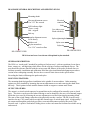
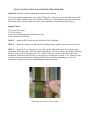
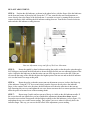
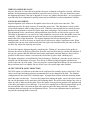
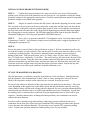
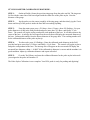
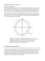
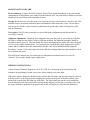
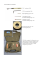
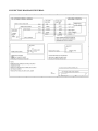
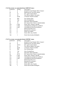
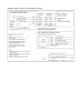
DP-4 Touch Probe
Operator's Manual
U.S Patent #6553682
Rev 2013-09-23
Copyright © 2003-2013 Centroid Corporation
Howard, PA 16841
DP-4 Quick Start Guide
1. Install MPU11 Probe cable assembly #11085 if necessary. Refer to Common Cables picture on
page 11, connection diagram on page 12 and appropriate appendix data.
2. Connect coil cord to DP-4 and to bulkhead connector on probe cable assembly #11085. See
probe features and general description page 1. LED indicating light should be green when
connection is made then turn red when stylus mount boss is touched.
3. Set system control parameters. See “Table of Contents” to locate application specific appendix.
See “Output Switch Logic Selection” page 5 if application requires a normally closed probe
output connection.
4. Confirm machine is responding to DP-4 input by running an automatic cycle without the probe
in the spindle and manually touching the DP-4 stylus mount boss. Refer to control operator's
manual for automatic probing cycles.
5. Install the DP-4 and tool holder in the spindle then install the stylus in the DP-4. See Stylus
installation procedures on page 3 and perform run-out adjustment as shown on page 3 and 4.
6. Review stylus travel limits on page 2 and follow the detailed initial setup on page 6 to perform
an automatic probing cycle at reduced speed.
7. Calibrate stylus tip size. See procedures on page 6.
8. Review “Performance Characteristics” page 8 to ensure good results.
9. Review Adjustments page 3,4 and 5 and Maintenance and Care page 9 to keep DP-4 in good
operational condition.
10. Probe is now ready to use.
TABLE OF CONTENTS
General Description
Page 1
Specifications
Page 2
Stylus Installation and Alignment Procedures
Run-out Adjustment “Dialing-in”
When to check run-out and dial-in
Angular Alignment Adjustment
Page 3
Output Switch Logic Selection
Page 5
Initial Control/Probe Setup Procedure
Page 6
Stylus Tip Diameter Calibration
Page 6
Performance Characteristics
Page 8
Maintenance and Care
Page 9
Shipping Instructions
Page 9
Kit Contents
Page 10
Common Cables
Page 11
Connection Diagram (universal)
Page 12
Grid Digitizing Tips
Page 13
Cutting a Copy of Digitized Part, Tips
Page 14
Appendix A – Centroid Control System Application
Default Parameters SAE and Metric
Connection drawing for Centroid Systems
Page 1
Page 3
DP-4 PROBE GENERAL DESCRIPTION AND SPECIFICATIONS
Mounting shank
Run-out adjustment screws
Use 3/32” hex wrench
LED indicator light
Green = ready
Red = tripped
Electrical
connector
Body
Core index screw
Flush with body
End cap
Angular alignment screws
Set at factory
Rubber seal
Stylus mount boss
Use 3/16” wrench on flats
DP-4 FRONT VIEW
Stylus tightening hole
Stylus stem
Stylus tip
DP-4 REAR VIEW
DP-4 front and rear views shown with optional stylus attached.
GENERAL DESCRIPTION:
The DP-4 is a “touch probe” intended for probing to find part zero’s, reference positions, locate bores,
bases, corners etc., and digitizing which allows for the copying of surfaces and shaped objects. The
user should first become familiar with the various parts and features of the probe as shown above to
facilitate assembly, installation and calibration. Read the stylus installation and alignment procedures
section before attempting assembly. Review the over-travel limits shown in the specifications.
Exceeding the limits will damage the probe and stylus.
MOUNTING FEATURES:
The mounting shank design allows installation in the spindle of most machines. Other mounting
options are easily installed by loosening the run-out adjustment screws and removing the shank from
the body. These options include smaller diameter shank or magnet or custom made forms.
OUTPUT FEATURES:
The output is a virtual switch connected to ground that can be configured for normally open or closed
logic. This choice can be specified when ordering or can be changed by the user via an internal jumper
block that is accessed by loosening the run-out adjustment screws and removing the mounting shank.
The state of the switch changes when the stylus physically touches a surface. The DP-4 can be easily
interfaced to any CNC control which accepts this common type of switch input signal. A high quality 5
pin connector through the probe body provides a convenient disconnect point for the stock 6 foot
retractile cord. A positive lock/unlock sliding sleeve on the cord connector facilitate fast reliable set-up
and removal.
DP-4 SPECIFICATIONS:
Probing directions
Unidirectional repeatability (2 sigma)
Probe deflection force (X,Y)
Pre-travel variation X-Y plane
Probe deflection force (Z)
Probe body diameter and length
Mounting shank diameter and length
Stylus mount thread
Output signal
Output logic
Power supply required
LED status indicator
Weight of probe and ½”shank
Over travel limit angle (X,Y)
Over travel limit (Z-)
Environmental
X+/-, Y+/-, Z0.00004” (1 micron)
3 ounce minimum with 40mm stylus
0.001” with 40 mm stylus
9 ounce minimum
D= 1.25” (31.8mm) L= 2.2” (56.4mm)
D= 0.5” (12.7mm) L= 1.47” (37.2mm)
M3
Switch (FET open drain) 30V 50mA
Selectable normally open or closed
10 – 30 VDC 50mA
green = ready, red = tripped
0.45 lb
+/- 10 degrees from vertical
0.15” (3.8mm)
IP54, Dust Proof
STYLUS INSTALLATION AND ALIGNMENT PROCEEDURES
Important: Read the complete alignment procedure before starting.
The run-out adjustment procedure, also called “Dialing-in” is necessary to ensure that the center of the
probe tip is aligned with the center of the spindle rotation axis. This eliminates any undesired off-sets
between the probe and the cutting tool centers when digitizing or doing automated part set-up.
Required Tools:
3/16” open end wrench
3/32” hex wrench
0.001" or better Dial Indicator with Magnetic Base
0.500" Dedicated Tool Holder
STEP 1:
Install the DP-4 Probe into the dedicated 0.500" tool holder.
STEP 2:
Install the complete assembly into the milling machine spindle without the retractile cord.
STEP 3: Install the 2.5 or 5mm stylus in your DP-4 probe. Thread the stylus into the probe stylus
mount boss until finger tight. Insert the stylus tightening pin, from your tool kit, into the hole located at
the base of the stylus stem and place the 3/16" wrench, from your tool kit, on the flats of the stylus
mount boss. Refer to the picture below. Do not apply any twisting force with the 3/16" wrench; use the
wrench to counter the twisting force being applied to the stylus by the tightening pin. Excessive
twisting force applied to the probe could damage the sensor assembly!
Tightening stylus with wrench and pin
RUN-OUT ADJUSTMENT:
STEP 4: Position the dial indicator, as shown in the photo below, with the finger of the dial indicator
on the front and center of the stylus ball. Insert the 3/32” hex wrench in the run-out adjustment set
screw directly above the finger of the dial indicator. Loosen the set screw by turning the hex wrench
counter clockwise while watching the dial indicator reading decrease. Turn the hex wrench clockwise
and watch the dial indicator reading increase.
Run-out Adjustment set-up and effect of Set Screw Movement
STEP 5:
Rotate the spindle by hand (without touching the probe) so that the probe spins through a
full 360 degrees and watch the dial indicator to locate the high and low run-out rotation positions of the
stylus. Adjust the dial indicator so that the entire run-out of the tip can be seen on the dial. If the runout exceeds the range of the dial then begin at the highest point of the run-out and set the dial indicator
so it is at the limit of its range at this point.
STEP 6:
Rotate the probe so that the nearest run-out adjustment set screw is above the finger tip
of the indicator. Using the 3/32" hex wrench slowly turn the setscrew directly above the indicator
finger, in the counter clock-wise direction, the dial indicator will show the reduction in the run-out.
Stop loosening this set screw and tighten the set screw that was nearest the low run-out position. Do not
allow the probe to become loose on the mounting shank.
STEP 7:
Repeat steps 5 and 6 until no run-out of the tip is visible on the dial indicator needle. If
the screws become too tight before you have finished the adjustment, do not force them, instead
loosen the setscrew that corresponds with the highest reading on the dial indicator, (refer to figure 3.2)
and tighten the set screw at the lowest reading. Only adjust a set screw when it is directly above the
indicator finger. This way you can see the full effect of the adjustment you are making.
WHEN TO CHECK RUN-OUT:
Any time the probe is removed from its holder, the stylus is changed or the probe is used in a different
machine, the alignment procedure should be repeated to ensure accuracy. The user should also repeat
the alignment procedure if the unit is dropped or receives any sudden external shock. It is good practice
to periodically check alignment for quality control and to establish a base line maintenance schedule.
ANGULAR ALIGNMENT:
Angular alignment is the relation of the spindle center line to the stylus stem center line. This
adjustment provides for equal clearance all around the stylus stem. This adjustment is rarely needed
except when extremely small or long stylus is used. When the stylus tip and stem are nearly the same
diameter this adjustment is critical to keep the stem from contacting a vertical surface before the tip.
This adjustment is also convenient to adjust parallelism when flat disc or block stylus types are used.
The range of adjustment is very small as it is only intended to correct the stylus and spindle center line
continuity. If this adjustment must be performed use the run-out adjustment set-up shown above to
monitor the effect of the adjustment. The angular alignment and run-out adjustments are
interdependent. It will be necessary to repeat each several times to achieve significant results. When
completed, the run-out at the stylus mount end of the stylus stem should be nearly the same as the runout at the tip. Adjust the stylus tip run-out last.
To check the angular alignment begin by completing the “Dialing-in” procedures for the probe tip.
Measure the run-out at the base of the stylus stem (the end away from the tip) with the dial indicator. If
the run-out is greater than the difference between the tip diameter and stem diameter then it will be
possible for the stem to contact a vertical surface before the tip (also called “shanking out”).
The angular alignment is accomplished by first performing a “Dialing-in” procedure on the stem base
using the run-out adjustment set screws. Next, the tip is dialed-in using the angular adjustment set
screws in the end cap of the probe. These two steps are repeated until the difference in run-out between
the tip and stem base is acceptable. Be sure all set screws are equally tight when finished.
OUTPUT SWITCH LOGIC SELECTION:
The DP-4 output is a solid state switch that can be configured for normally open or closed logic. This
choice can be specified when ordering (recommended) or can be changed in the field. The standard
configuration for the stock DP-4 is normally open. A jumper block located under the mounting shank
inside the probe sets the logic. To access the jumper block unplug the probe, remove the stylus, loosen
the run-out adjustment screws and remove the mounting shank. Be careful not do damage any wires or
allow any dirt or debris inside the probe. Move the jumper from its present position to the opposite end
of the three pin header to invert the logic. Use tweezers or small pliers to slide the jumper block up off
the pins and then slide it down on the pins at the opposite end of the three pin header. Install the
mounting shank and snug the run out adjustment screws. The run out adjustment must be performed
any time the mounting shank is removed.
INITIAL CONTROL/PROBE SETUP PROCEDURE
STEP 1:
Confirm that control parameters are setup correctly for your system. The automatic
probing cycles will not work if the parameters are not correctly set. See appendix to check the default
parameter settings for the appropriate control system. Check the control operation manual if compatible
parameter settings are not found in the appendix.
STEP 2:
Plug the 6' retractile cord into the DP-4 probe and into the digitizing port on the control.
The cord ends are keyed to prevent incorrect connection. At the probe end line-up the red dot with the
red painted slot on the probe connector, push the plug in until it clicks. At the opposite cord end insert
the large black connector and rotate until it drops into the digitizing port connector then finger tighten
the securing ring to seat the connector. The LED indicating light on the front of the probe should be
illuminated bright green. Touch the probe tip and the LED should turn red.
STEP 3:
Press <Alt+I> to open the centroid PLC I/O diagnostic screen. Locate the inputs entered
in parameters 11 and 18. Verify that they change correctly when the probe is triggered (parameter 11)
and plugged in (parameter 18).
STEP 4:
Review the probe overtravel limits in the specifications on page 2. Perform an automatic probe cycle
test with the feedrate over ride reduced to 20% and the stylus 10 inches away from any object to verify
everything is working together. Be prepared to manually stop the machine to prevent overtravel
damage to the probe. From the main screen, press <F1-Setup>, then <F1-part>, then <F5-Probing>,
then <F7-Single Axis>, and finally <Cycle Start>. The control will jog the stylus in the direction of the
single axis move selected. Touch the stylus once and the control will stop and reverse travel the probe
clearance amount then stop and then resume motion in the single axis direction at the slow probe rate.
Touch the stylus once and the control will stop and display a position window. Repeat this step and
adjust parameters as needed to gain confidence using the automated cycles.
STYLUS TIP DIAMETER CALIBRATION:
The final procedure is to calibrate your probe stylus diameter for the tool library. Although the ruby
ball (tip) diameter of the furnished styli is either 2.5mm or 5mm, entering these values in the tool
library will not produce accurate results unless they are corrected for stylus pre-travel.
Pre-travel is the amount of deflection of the stylus tip before the probe detects the surface. This value
varies depending on the length of the stylus and the speed and direction that the stylus tip is moving
when it makes contact with the surface being probed or digitized. Pre-travel variation amount should be
stated in probe specifications relative to stylus length and direction of travel limitations. A probe that
has small pre-travel variation with no restriction on stylus length and direction of travel will be quite
expensive. Machine characteristics including lash and input latency also contribute to the need to
calibrate the stylus diameter.
In order to achieve optimal results when probing or digitizing you must calibrate the tip size to
compensate for the sum of the effects previously mentioned. The following procedure is the quickest
way to determine the calibrated diameter. This procedure uses Centroid (TM) automatic probing
cycles. Consult your operation manual for similar probing cycles for your machine.
STYLUS DIAMETER CALIBRATION PROCEDURE:
STEP 1:
On the mill table, fixture the precision ring gauge from the probe tool kit. The ring must
lie flat with the center line of the bore aligned with the center line of the probe stylus. Note the
diameter of the gauge.
STEP 2:
Jog the probe over the center (roughly) of the ring gauge, and then slowly jog the Z-axis
down until the tip of the probe is inside the bore and not touching anything.
STEP 3:
From the main screen, press <F1-Setup>, then <F1-part>, then <F4-Probing>, Set your
probe diameter to 0.000 in the field provided and press enter, then <F1-Bore>,and finally <Cycle
Start>. The control will jog the stylus to and probe each quadrant of the bore. It will then return to the
center of the bore. A message box will appear on the screen that will display the measured diameter of
the bore. Subtract this number from the known diameter of the gauge bore. The resulting number will
be the calibrated diameter of the probe stylus tip.
STEP 4:
Test the result. press <F4-Probing>, Enter the calibrated probe diameter in the field
provided and press enter, then <F1-Bore>,and finally <Cycle Start>. The control will jog the stylus to
and probe each quadrant of the bore. The message box will appear on the screen and will display the
measured bore diameter within +/- 0.0002" if the calibrated tip diameter is correct and the machine is in
good condition. Adjust tip calibration diameter and repeat as needed.
STEP 5:
Go to the Tool Library and enter the calibrated diameter for the probe stylus in the tool#
you assigned to the probe in Parameter 12.
The Probe Stylus Calibration is now complete. Your DP-4 probe is ready for probing and digitizing!
PERFORMANCE CHARACTERISTICS
PRE-TRAVEL VARIATION:
Pre-travel is the amount of deflection of the stylus tip before the probe output switches. This value
varies depending on the length of the stylus, speed and direction that the stylus tip is moving relative to
the target surface when it makes contact. Pre-travel variation amount should be stated in probe
specifications relative to stylus length and direction of travel limitations. A probe that has small pretravel variation with no restriction on stylus length and direction of travel will be quite expensive.
Machine characteristics including lash and input latency also contribute to pre-travel variation. Pretravel variation errors can be easily avoided by always taking data in the same directions and speed.
The pre-travel then becomes a constant and can be accounted for in the calibration procedures then
accuracy becomes dependent on repeatability.
PRE-TRAVEL VARIATION, RADIAL DIGITIZING PRECISION BORE
Typical pre-travel variation for DP-4 probe showing variation over 720 degrees of
radial digitizing routine of precision bore. Inside circle represents the
minimum value and the outside circle the maximum. Data was collected
probing at 1 inch per minute with a 43mm long stylus.
UNIDIRECTIONAL REPEATABILITY:
This specification indicates a 95% confidence level that repeated measurements will not vary more than
+/- the stated amount (standard deviation at 2 sigma level). The stated amount only applies to repeated
measurements in the same direction and speed. Machine characteristics can drastically reduce the
confidence level in this specification. A probe installed on a CMM has a much better chance of
producing the stated tolerance than one installed on a mill since the machine errors add to the probe
error. That said, mill installations can still produce results well within the tolerances allowed for
machining if the mill is kept in good operating condition.
MAINTENANCE AND CARE
Do not submerge or expose the DP-4 to liquids. Wipe off any liquids immediately to prevent internal
contamination or degradation of the rubber seal and indicator lens. The probe body is stainless steel and
should only be wiped clean with compatible cleaners.
Storage. When not in use, store the probe in a vertical or inverted vertical position, not on its side. This
minimizes stress on internal mechanical parts and distributes lubrication more evenly. Do not ship or
store the probe with the stylus mount boss pushed into the probe body as this will negatively affect
internal lubrication.
User repairs. The DP-4 has no internal user serviceable parts or adjustments and should only be
serviced by Centroid.
Alignment adjustments. Regularly check alignment. Any time the probe is removed from its holder,
the stylus is changed or the probe is used in a different machine, the alignment procedure should be
repeated to ensure accuracy. The user should also repeat the alignment procedure if the unit is dropped
or receives any sudden external shock. It is good practice to periodically check alignment for quality
control and to establish a base line maintenance schedule. See "Stylus Installation and Alignment
Procedures" section. If the probe stylus can not be dialed-in or aligned then the probe should be sent in
for evaluation and repair.
The DP-4 has no internal user serviceable parts or adjustments and should only be serviced by
Centroid. If your probe should require repair please
SHIPPING INSTURCTIONS
Contact Centroid Technical Support at 1-814-353-9290 for a description of the return policy and
assistance in determining if return is necessary, before sending your probe back.
If the probe must be shipped it should be removed from the tool holder and the stylus must be removed
from the probe. Use the original plastic shipping tube and insert the probe in the tube with the stylus
mount boss located inside the foam ring in the tube. The foam should prevent the stylus mount boss
from touching the end of the plastic tube if jarred during shipping. Do not ship or store the probe with
the stylus mount boss pushed into the probe body as this will negatively affect internal lubrication.
DP-4 PROBE KIT CONTENTS
3/16” wrench p/n: 2902
3/32” hex wrench p/n: 2898
Stylus tightening pin p/n: 2903
2.5mm Ruby tip stylus
M3 thread 40mmlength p/n: 3357
5mm Ruby tip stylus
M3 thread 40mmlength p/n: 3360
Precision ring gauge p/n: 3193
Size and type may vary
DP-4 Probe complete kit with protective case
and accessories. Inset shows outside of case.
Kit contains the accessories shown above
plus the retractile coil cord p/n: 10394.
Complete kit p/n: 10395
COMMON CABLES:
The photo below shows the DP-4 connected to the primary cable assemblies common to all
installations. Note the bulkhead connector to provide physical support for the coil cord. No additional
adapters are needed for new Centroid (TM) systems. See the appropriate appendix in the DP-4 manual
for additional required adapters, connection diagrams and parameter settings for your installation.
MPU11 Probe Cable P/N:11085
Internal wiring harness with fuse
holder and bulkhead connector to
mate with COIL CORD.
COIL CORD
P/N: 10394
DP-4 Probe shown connected to retractile coil cord and internal
wiring harness with bulkhead connector and fuse holder.
CONNECTION DIAGRAM UNIVERSAL
GRID DIGITIZING TIPS
Digitizing is, by its nature, a slow, precise process. The time it takes to digitize a part is effected by
four factors: feedrate, step size, detail density and over-all shape of the object.
The feedrate settings in parameters 14 and 15, (the fast and slow probing rates). As a general rule of
thumb parameter 14 should be set to 20 or 30ipm for digitizing and probing. This setting will not affect
the accuracy of the digitizing data, but will speed up the approach cycles during the digitizing run and
there by reduce the time the run takes. Parameter 15 however does have a direct effect on the accuracy
of the digitizing data and should be adjusted to match the tolerances you are calling out for the finished
part. Typically setting this parameter slower will yield more accuracy and faster less accuracy.
The accuracy achieved on vertical surfaces is also dependent on stylus length and related PTV (pretravel variation) for the probe being used. If vertical surface accuracy greater than the PTV value is
needed then a probe with appropriate PTV is required such as the DP-7.
If your part does not require very close tolerances then adjusting these probing rates could save you a
significant amount of time, but if you set the feedrate too high the results you get may not meet your
requirements and you will just be wasting time. So start off cautiously, it is better to take a little longer
when you are first starting out. Once you have several digitizing runs under your belt, you will have a
much better feel for where these parameters need to be set to achieve the results to meet your job
requirements.
The X, Y, and Z stepover – The smaller the stepover distance, the longer the digitizing run. For
instance the typical time it takes to digitize a 1” by 1” grid with a step over of .010” in X, and .010” in
Y, (with parameters 14 and 15 set to 30ipm and 5ipm respectively), is 45 minutes with 10,000 data
points being recorded. By changing the X stepover to 0.005” and the Y stepover to 0.005” the time
increases to 3 hours with the number of data points recorded increasing to 40,000. The trade off with
time, is surface finish and detail. The finer the stepover amount in the digitizing run the better the
surface finish is going to be in the final part and the more fine detail you will be able to capture. As the
end user, it is up to you to find the settings that give you the finish, and detail level you are looking for
in the final part.
Remember, the Centroid control can digitize unattended, 24 hours a day, 7 days a week, if you really
need the detail and finish, (just remember to fill the automatic oiler tank!).
The third factor that affects the time it takes to digitize a part is the density and height of the surface
detail. The more vertical walls the probe stylus must climb, up and down over, the longer the digitizing
will take. This is not a factor you have much control over, except for adjusting your Z stepup distance,
but in general this will have little effect.
Finally, if the piece is odd shaped, you may want to patch several small digitizing runs together and
there by eliminate the wasted time that would be spent moving over areas that are not pertinent to the
data you want to collect.
CUTTING COPY OF DIGITIZED PART TIPS:
The following are some tips on using the data from your completed grid digitizing run. The
nomenclature, procedures and programs used are consistent with the Centroid(TM) operators manual.
Consult your operator's manual for equivalent.
When you are ready to cut a copy of the part you have digitized, set your part up using the same X, Y,
and Z coordinate you used to digitize the part. The digitizing program does not put in the M codes and
spindle speed setting. You must either turn the spindle on manually or edit the G-code file and insert
this information. Simply insert a line at the beginning of the program that contains M3 (spindle
clockwise) or M4 ( spindle counter clockwise) followed by an S with the speed you want to turn the
spindle at.
The following is an example: M3 S4000
This will turn the spindle on going clockwise at 4000 RPM. To turn the spindle off when the program
finishes put a M5 at the end of the program.
You can also use the text editor to turn coolant on and off by adding, M7 (MIST), or M8 (FLOOD) at
the beginning of the program, and M9 (COOLANT OFF) at the end. Remember you can have only
one-M code per line in the program.
To enlarge, shrink or mirror your part, you can use the G51 (turns on scaling) and G50 (turns off
scaling) commands, (refer to your user manual for the complete description and definition of these G
code commands). When enlarging or shrinking your part using the G51 command remember you must
scale the size of the cutter you are going to use to cut the part by the same factor that you use to scale
your part. For instance if you digitized a part with a 0.25” stylus and scale the part up by 2 then the
cutter needed to cut the part would be a 0.5” diameter cutter. Conversely if you scale the part by ½
then the cutter diameter needed would be 0.125”.
You can also import your digitized data into an online CAM program on your Centroid control or
export it to an offline CAM system. The “Dig to CAD” menu in the Digitizing screen is used to convert
the digitized data to a format that can be used by the CAM programs.
APPENDIX A
CENTROID CONTROL SAE PROBE PARAMETERS
(see control manual for additional information)
CNC10 systems (recommended basic SAE inch):
Parameter
Setting
Description
3
0
Modal Tool and Height Offset Control
10
0
Enables decel on probe contact
11
14
Probe / TT PLC probe input number
12
10
Tool library number for probe
13
0.020
Clearance amount nominal
14
30
Fast Probing Rate
15
3
Slow Probing Rate
16
5
Maximum Search Distance
18
15
PLC input, Probe Detect, Spindle Inhibit
120
0.020
Probe stuck clearance amount
121
0.020
Grid digitizing minimum Z pullback
122
0.0002
Grid digitizing dead band distance
123
0
Radial clearance move
151
0
Repeatability tolerance
155
0
Probe type enable
186
0
Probe stuck retry disable
366
1
Probe Deceleration Multiplier
CNC11 systems (recommended basic SAE inch):
Parameter
Setting
Description
3
0
Modal Tool and Height Offset Control
10
0
Enables decel on probe contact
11
50769
PLC probe input number
12
10
Tool library number for probe
13
0.020
Clearance amount nominal
14
30
Fast Probing Rate
15
3
Slow Probing Rate
16
5
Maximum Search Distance
18
50771
PLC input, Probe Detect, Spindle Inhibit
120
0.020
Probe stuck clearance amount
121
0.020
Grid digitizing minimum Z pullback
122
0.0002
Grid digitizing dead band distance
123
0
Radial clearance move
151
0
Repeatability tolerance
155
0
Probe type enable
186
0
Probe stuck retry disable
366
1
Probe Deceleration Multiplier
CNC10 systems (recommended basic METRIC mm):
Parameter
Setting
Description
3
0
Modal Tool and Height Offset Control
10
0
Enables decel on probe contact
11
14
PLC probe input number
12
10
Tool library number for probe
13
0.508
Clearance amount nominal
14
762
Fast Probing Rate
15
76.2
Slow Probing Rate
16
127
Maximum Search Distance
18
15
PLC input, Probe Detect, Spindle Inhibit
120
0.508
Probe stuck clearance amount
121
0.508
Grid digitizing minimum Z pullback
122
0.005
Grid digitizing dead band distance
123
0
Radial clearance move
151
0
Repeatability tolerance
155
0
Probe type enable
186
0
Probe stuck retry disable
366
1
Probe Deceleration Multiplier
CNC11 systems (recommended basic METRIC mm):
Parameter
Setting
Description
3
0
Modal Tool and Height Offset Control
10
0
Enables decel on probe contact
11
50769
PLC probe input number
12
10
Tool library number for probe
13
0.508
Clearance amount nominal
14
762
Fast Probing Rate
15
76.2
Slow Probing Rate
16
127
Maximum Search Distance
18
50771
PLC input, Probe Detect, Spindle Inhibit
120
0.508
Probe stuck clearance amount
121
0.508
Grid digitizing minimum Z pullback
122
0.005
Grid digitizing dead band distance
123
0
Radial clearance move
151
0
Repeatability tolerance
155
0
Probe type enable
186
0
Probe stuck retry disable
366
1
Probe Deceleration Multiplier
PROBE CONNECTION TO CENTROID CONTROL