1
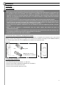
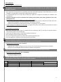
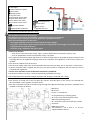
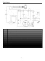
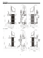
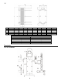
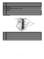
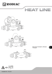
35-70-120-240 Instructions for installation and use English Ver. : 04/2011 EN Contents Installation .......................................................................................................... 2 1.1 General ..................................................................................................................................................2 1.2 Operating conditions ............................................................................................................................2 1.3 Installation ............................................................................................................................................3 Operation ........................................................................................................... 5 2.1 Presentation of the control unit (for UP + only) ...................................................................................5 2.2 Setting the setpoint temperature (for UP + only) .................................................................................5 2.3 Starting the appliance ...........................................................................................................................5 2.4 Checks to be carried out after operating for a few moments ..............................................................6 2.5 Winter storage ......................................................................................................................................6 Maintenance ....................................................................................................... 6 3.1 Maintenance instructions .....................................................................................................................6 3.2 Recycling ...............................................................................................................................................6 Troubleshooting (for UP + only) .......................................................................... 7 4.1 The display does not work ....................................................................................................................7 4.2 The appliance displays a flashing “E0” ..................................................................................................7 4.3 The pool water is hotter than requested ..............................................................................................7 4.4 Fuse replacement..................................................................................................................................7 Technical information ......................................................................................... 7 5.1 Technical characteristics .......................................................................................................................7 5.2 Modification of the maximum setpoint temperature (for UP + only) ..................................................8 Warranties .......................................................................................................... 8 Online registration .............................................................................................. 9 Declaration of conformity ................................................................................... 9 Appendices at the end of the manual: - wiring diagrams - dimensions - description Please read this manual carefully before installing, maintaining or repairing this appliance! The symbol indicates important information that must be taken into account in order to avoid risk of personal injury and/or damage to the appliance. The symbol indicates useful information. 1 Installation 1.1 General 1.1.1 Precautions Exclusive use: pool water heating (must not be used for any other purpose). The product must be installed by a qualified technician according to the manufacturer’s instructions and in compliance with local standards. The installer is responsible for the correct installation of the appliance and also for ensuring compliance with local regulations. The manufacturer shall not be held liable for any potential issues that may occur as a result of failure to comply with local standards pertaining to installation. Incorrect installation may cause serious property damage and/or personal injury (possibly death). This appliance must be handled by competent and qualified personnel (physically and mentally) who are familiar with the operating instructions (by reading the user guide). Anyone not fulfilling these criteria must not go near the device to avoid exposure to dangerous elements. In the event of an appliance malfunction: do not attempt to repair the appliance yourself, call your installer. Make sure the appliance is disconnected from the mains supply and locked out prior to maintenance/servicing. Removing or shunting any of the appliance’s safety elements will automatically void the warranty. Use only original manufacturer parts when replacing faulty or worn parts. Keep the appliance out of the reach of children. 1.1.2 General terms of delivery, storage and transport All equipment, including CARRIAGE and PACKING FREE deliveries, is shipped at the recipient’s risk. In the case of damage caused during shipping, the recipient must mention any reserves in writing on the CARRIER’S delivery note (confirmation to be sent to the CARRIER within 48 hours by registered mail). Contents: UP + + 2 x + 2 x UN Ø50, glued Ø20/22 (UP + 35‐70) or Ø26/28 (UP + 120‐240) or 1.2 Operating conditions Operating range: pool water temperature between 2 °C and 40 °C, primary circuit water temperature between 45 °C and 90 °C, primary circuit service pressure: 2 bar, primary circuit maximum pressure: 3 bar. 2 1.3 Installation 1.3.1 Selecting an installation site The appliance must be installed in a technical compartment (ventilated, dry and without stored pool treatment products). The appliance must be placed on a solid base, level and raised off the ground in cases where there is a risk of flooding or if the ground is cleaned with a high‐pressure water jet. An unobstructed space of at least 80 cm around the appliance is required to facilitate its installation and maintenance. Install the appliance as close as possible to the heating source (boiler, heat pump, geothermal unit, solar heating unit, etc.). If the appliance cannot be installed next to the heating source: - Provide piping of appropriate size for the primary and secondary circuits in relation to the water flow rate, head losses and distance, and ensure that they are properly insulated. - Install a more powerful circulating pump (contact us regarding its size and supply). If the exchanger is located far from the filter: the pipes of the pool circuit must be at least Ø50 and routed through a protective conduit if buried. 1.3.2 Hydraulic connections The water treatment system must be installed after the exchanger and at a low point to prevent chlorine from returning back into the exchanger. Check that the piping system is clean before making connections. The exchanger must not support the piping. Do not use rapid closing valves to prevent the hammering phenomenon. Correctly tighten the hydraulic connections and check for leaks. Observe the hydraulic connection direction (see label on the appliance), to optimise the exchange of calories. The water coming from the heating source must be at constant temperature. heating system connection (a.k.a. primary): - use insulated pipes; - equipped with a safety valve (pressure set at 3 bar) and correctly dimensioned expansion chamber; - the pipes must be equipped with automatic air bleeders at high points. Branch connections on the primary circuit must be placed upstream from all valves or pumps. connection of the pool system (a.k.a secondary): - use Ø50 PVC pipes minimum, - mandatory through a by‐pass. On UP +: 90° elbow fittings must not be installed directly at the exchanger outlet; leave at least 25 cm of straight pipe to prevent chatter of the flow controller armature. Primary connection Secondary connection 35‐70 120‐240 35‐70 120‐240 UN 20/27 male, screw type 26/34 male, screw type Ø20‐27 male, screw type Ø26‐34 male, screw type UP + 26/34 male, screw type 33/42 male, screw type Ø50, glued 3 A: exchanger water treatment system pool system heating system V1: by‐pass valve V2: pool water outlet valve V3: pool water inlet valve V4: hot water inlet valve * V5: hot water outlet valve * automatic bleeder solenoid valve (optional) circulating pump * check valve * drain valve * * supplied with UP + 1.3.3 Electrical connections (for UP + only) Risk of electric shock inside the appliance. The appliance must only be connected by a qualified and experienced technician. If the power cable is damaged, it must be replaced by a qualified technician. Check the following before all operations: - the voltage indicated on the unit corresponds to the mains voltage; - the power outlet and the power supply network are appropriate for exchanger use and that they are equipped with an earth connection; - the power plug is adapted to the power outlet. Electrical protection: ‐ either by a 5 A fuse disconnector with, upline, a 30 mA differential circuit breaker (rating > 5 A), ‐ or by an independent 30 mA circuit breaker (rating: 5 A) upline. The single‐phase electrical supply (230 V‐50 Hz) of the exchanger must be provided through a protection and switching device (not supplied) complying with current standards and regulations in the country where it is installed. The electrical conduits must be secured. The electrical supply cable must not be exposed to elements that are sharp, hot or represent a crush hazard. Connect the power cable, supplied with the unit, to a power outlet in compliance with the country's current standards and regulations. All use of an extension cord or multisocket connection is prohibited. If the power cable is too short, it must be replaced by a qualified technician. 1.3.4 Connection of an external control to power the primary circuit (for UP + only) Use a 3G1 cable (cross‐section 1 mm²). This function is carried out via the non‐polar dry contact “normally open at rest” (Imax 5 A at 250 VAC 50‐ 60 Hz) available on the regulator terminals 19‐20. The wire connected to terminals 19‐20 must go through the additional discharge “grommet” (supplied) to be installed on the base of the box. Ph: phase N: neutral F: fuse ‐ 5 A maximum C: complementary circulating pump V’: 3‐way valve with mechanical return CH: existing heating source V’’: motorized 3‐way valve with two rotation directions KA1: control relay The elements: C ‐ CH ‐ F ‐ KA1 ‐ V’ ‐ V’’ are not supplied with this device. 4 Operation 2.1 Presentation of the control unit (for UP + only) Heater indicator light (steady = heating in progress, flashing = on stand‐by) Digital display Temperature control buttons “On/Off“ indicator light “On/Off” button The temperature is controlled degree by degree. The setpoint value adjustment range is between 2 °C and 40 °C. This maximum temperature may be decreased to protect the swimming pool liner (see §5.2). 2.2 Setting the setpoint temperature (for UP + only) Display and modify the setpoint value by pressing either or . Pressing and holding either of these two buttons allows rapid change of the setpoint value. 2.3 Starting the appliance If the primary circuit circulating pump has not been in operation for a long time, check that it has not seized: with the circulating pump off, unscrew the pump's front panel (water may flow out), then use a screwdriver to turn the motor shaft. Never circulate water in the primary circuit without water circulating in the secondary circuit. Fully open valves 1, 2 and 3 (see §1.3.2). Start the filtration pump. Check the pool water circulation in the exchanger. Perform an initial adjustment of the by‐pass by closing valve 1 slightly (see §1.3.2) (+ 150 to 200 g for Uranus 35‐70, + 300 to 400 g for Uranus 120‐240 on the filter pressure), in order to more or less obtain the nominal secondary water flow rate. Adjust the valves (valves 4 and 5 fully open (see §1.3.2)). The flow rate must be adjusted slowly to avoid hammering. Check the filling and degassing of the heating circuit. Turn on control unit power, then start it. Adjust the setpoint temperature. Adjust the by‐pass using valve 2 (see §1.3.2) for correct operation. On UP +: If the setpoint temperature is greater than the pool water temperature: ‐ the “reg” indicator light flashes for 15 seconds; ‐ then remains steady; ‐ the circulating pump should operate. If the water flow rate is too low (less than 1.1 m³/h), or if the filtration is stopped, the “reg” indicator light will flash and the water in the primary circuit will stop circulating. When the pool has reached the desired temperature, the “reg” indicator light goes out, and water in the primary circuit will stop circulating. 5 2.4 Checks to be carried out after operating for a few moments Check for leaks. Check that the fluid temperatures and pressures do not exceed the limits indicated on the appliance's rating plate. Check that the circulating pump stops when: - the setpoint temperature is decreased or when the control is shut off; - filtration is stopped, or when valve 2 or 3 is closed (see §1.3.2). Check that the exchanger is no longer irrigated by the heating circuit when the filtration is stopped, and when there is no request to heat the pool water. 2.5 Winter storage Winter storage is imperative if the technical compartment runs the risk of freezing. Damage caused by improper winter storage is not covered by the warranty. Turn off control unit power. Shut off water circulation in the primary and secondary circuits. Drain the primary circuit (be careful of the water temperature, wait for it to cool down to avoid the risk of burns): - close shut‐off valves 4 and 5 (see §1.3.2); - open the drain valve. Drain the secondary circuit: - close valves 2 and 3 (see §1.3.2); - unscrew the fittings to drain the exchanger; - when the exchanger is empty, lightly retighten the fittings. Maintenance 3.1 Maintenance instructions It is recommended that general servicing of the appliance be performed on a yearly basis to ensure proper operation, preserve performance and prevent potential failures. Contact your installer to replace the plates or seals and for plate maintenance. These actions are the responsibility of the user and must be performed by a qualified technician. Check the electrical components. Check the ground connection. Check that the electric cable connections are properly tightened and that the electric box is clean. Loose terminals may cause the terminal strip to overheat, and will void the warranty. 3.2 Recycling Has your appliance reached the end of its service life? Do you want to dispose of it or replace it? Do not dispose of it as household waste and do not use household recycling containers either. This symbol, displayed on new equipment, means that it must not be thrown away and that it is subject to waste sorting for reuse, recycling and conversion. Any substances it may contain which are potentially dangerous to the environment will be eliminated or neutralised. Contact your retailer regarding the applicable recycling conditions for your product and the organisations that can handle its recycling. 6 Troubleshooting (for UP + only) 4.1 The display does not work Power is not supplied to the appliance. The regulator fuse is blown (for replacement, see §4.4). 4.2 The appliance displays a flashing “E0” The control sensor is out of service or disconnected. Appliance power off and locked out, reconnect or standard replacement of the sensor. The “E0” fault is automatically cleared. 4.3 The pool water is hotter than requested The regulator is not operating correctly; check that the circulating pump stops when the setpoint temperature is reached. Another circulating pump is pushing on the primary circuit. If this is the case, install a solenoid valve on the outgoing leg of the primary heating circuit controlled by terminals 19‐20 (see §1.3.4). 4.4 Fuse replacement IMPORTANT! Disconnect power to the appliance! Remove the cover. Disconnect the regulator. Remove the regulator cover. Remove the fuse (T3, 15AH250V). Technical information 5.1 Technical characteristics UP + / UN Unit Primary °C 90 Secondary °C Power kW 35 Primary Flow m³/h rate Secondary Primary 0.8 Head mCE loss Secondary 1.8 Available manometric mCE 4 height, primary* * with circulating pump installed on UP + UP + protection index: IP 34 35 60 26 27 1.5 1.5 0.9 1 0.9 1.1 3.9 3.9 0.4 1.7 70 60 26 38 1.5 3 0.5 1.6 4.4 4.3 45 90 15 70 0.5 1.7 120 60 26 120 60 3.5 4.7 4.1 2.1 2.1 3.9 2.9 4.1 2.2 2.8 240 60 26 240 120 6.3 8.6 2.1 2.2 4 4.3 3.5 3.4 1.9 45 21 90 3.5 45 32 90 1.8 45 66 2.2 1.8 5.1.1 UP + circulating pump characteristics UP + circulating pump centre‐to‐centre distance 35‐70 120‐240 UPS 25/60 UPS 32/80 130 mm 180 mm input power speed 3 70 W 240 W In capacitor 0.30 A 1.05 A 2.5 µF 400 V 5 µF 400 V 5.1.2 Plate characteristics UP + / UN Number of plates Plate type Thickness 35 70 120 240 15 25 17 31 T2 titanium T2 titanium M3 titanium M3 titanium 0.5 mm 0.5 mm 0.4 mm 0.4 mm Dimension E (average tightening) 45 mm 75 mm 47.8 mm 87 mm 7 5.2 Modification of the maximum setpoint temperature (for UP + only) Turn off the regulator (the “on” indicator light goes off, the pool water temperature is displayed). Simultaneously press and hold and for 5 seconds, “PA” is displayed. Press . Then enter the value “80” using the or keys (access code to the settings menu). Press to confirm this code, “PA” is displayed. Simultaneously press and hold and for 5 seconds, “/1” is displayed. Press to scroll through each parameter until “r2” is displayed. Press , the current value of the parameter “r2” is displayed. Press or to modify the maximum setpoint value. Press to confirm this new value. Simultaneously press and hold and for 5 seconds to return to the pool water temperature display. Warranties Principle Unless otherwise stipulated, we contractually guarantee the correct operation of our new products. We guarantee that our products are in compliance with their technical specifications and that they are free of material and manufacturing defects. This warranty is limited, at our discretion, to either repair or exchange for a new or reconditioned product, or to the reimbursement of any products deemed defective by us. Shipping expenses for the repaired or replaced products delivered to the customer shall be borne by us. The warranty excludes any labour costs, travel and/or accommodation expenses incurred as the result of repairs made outside continental France and excludes any payment of damages. All product returns must first be examined and approved by us. Returns sent by the customer will not be accepted without our prior approval. In particular, the spare parts warranty shall apply only after assessment and inspection of the returned parts by our company followed by the decision to replace such parts. In all cases, the seller’s legal warranty will continue to apply. In order to benefit from warranty coverage, the customer and the end user agree to comply with the following pool water characteristics: ‐ pH: 6.8 < pH < 7.6 ‐ free chlorine: < 3.0 mg/L ‐ total bromine: < 5.0 mg/L ‐ stabilising agent (if used): < 75 mg/L ‐ total dissolved metals (iron, manganese, copper, zinc, etc.): < 0.1 mg/L Comment: the use of well water is prohibited. General limitations This warranty does not apply to visible defects that the customer failed to report upon accepting delivery of the products. Also excluded from the warranty are: defects or deterioration due to the unsuitability of the product with respect to the end user’s needs, normal wear, negligence, incorrect installation or use not in compliance with the recommendations mentioned in the User Manual, lack of maintenance and/or handling accident, incorrect storage, and/or by studies, instructions and/or specifications made by our customer. Any modifications made to the products by our customer, the end user or any third party will automatically void the warranty in full. The same will apply if original parts are replaced with spare parts not sold by us. Our customer shall be responsible for ensuring the compatibility of our products with any other pool equipment used with them, by checking with the different manufacturers concerned, also for ensuring that all installation and operating instructions and commissioning operations are respected to ensure the correct operation of the entire system. In the case of a return of the product to our workshop, all shipping costs shall be borne by the end user, except for those mentioned in paragraph 2 of this article. Immobilisation of an appliance in case of repair shall not qualify for the right to compensation for loss of use. This warranty will be rendered void in the case of non‐payment or late payment by our customer for the product concerned. 8 Warranty period The effective warranty start date is the date mentioned on the sales invoice for the new product as issued by our customer to the end user. This document will be required as proof‐of‐purchase for all warranty claims. Failing this, our customer shall bear the full cost of any resulting losses/damages to our company, for all claims made by the end user after expiration of the contractual warranty period. No repair or replacement effected shall cause any extension or renewal of the warranty period. Special provisions for heating and dehumidification systems Unless otherwise specified, we guarantee the correct operation of our new products installed and commissioned by a professional installer (excluding installation via a “retrofit kit”) for a period of two years starting on the invoice date of the new product as issued by our customer to the end user. Users are also required to have an approved technician perform regular maintenance on our products, as detailed in the instructions in the product user guide. The warranty only covers material and manufacturing defects that have been acknowledged by our technical department/services. This warranty does not apply to malfunctions and/or damage due to external factors over which we have no control (incorrect power supply, adjustment of the bypass, incorrect air circulation, poor insulation of the premises, thermal bridges, incorrect winter storage, etc.). For all warranty issues, please contact your retailer. We recommend that you keep your purchase invoice in the event you should require assistance with your product. Online registration Register your product on our website: - be first to receive information about new Zodiac products and special offers; - help us to constantly improve the quality of our products. Australia – New Zealand South Africa Europe and rest of the world www.zodiac.com.au www.zodiac.co.za www.zodiac‐poolcare.com Declaration of conformity Z.P.C.E. declares that the products or ranges below: Special swimming pool heat exchanger: UP + 35‐70‐120‐240 are in compliance with the provisions of: the ELECTROMAGNETIC COMPATIBILITY Directive 89/336/EEC. the LOW VOLTAGE directive 73/23/EEC. As part of our continuous improvement policy, our products may be subject to change without notice. Version 04/2011 9 Electric diagram UP + CA TH M1 F1 CD So GG L1 L2 S1 19‐20 V‐J Bl M B N English Power supply cord: 2P+G 10/16A 3G1 control thermostat with digital display circulating pump motor fuse 3.15 A‐G flow controller pool water control sensor (PTC) grey conduit “on/off” LED flashing "reg" LED: timer active; steady: heating in progress “on/off” switch “normally open” control dry contact green‐yellow blue brown white black Ground 1 Dimensions UP + 35‐70 UP + 120‐240 2 UN UN 35 70 120 240 A 255 mm 255 mm 256 mm 407 mm B 230 mm 230 mm 200 mm 350 mm C D 380 mm 3/4" 380 mm 3/4" 500 mm 1’’ 500 mm 1’’ E 45 mm 75 mm 47,8 mm 87 mm F 140 mm 140 mm 200 mm 200 mm G 45 mm 45 mm 70 mm 70 mm H I J 50 mm 41 mm 298 mm 50 mm 41 mm 298 mm 60 mm 71,5 mm 357 mm 60 mm 71,5 mm 357 mm weight UP + 37 Kg 38 Kg 65 Kg 70 Kg UN 14 Kg 16 Kg 36 Kg 40 Kg Description UP + 35‐70‐120‐240 3 English 1 2 3 4 5 6 7 8 9 10 11 12 electric box frame tightening plate connection and sealing flange flow controller injected Tee with 20/27 male adapter, screw‐type control sensor thermowell ball valve circulating pump check valve drain valve UN 35‐70‐120‐240 2 1 3 7 5 6 English 1 2 3 4 5 6 7 fixed frame rating plate adjusting rods guide bar tightening plate heat exchange plates connecting pipes (with caps) 4 4 N o t e s - N o t e n - A a n t e k e n i n g - N o t a s - N o t a www.zodiac-poolcare.com Your retailer/ votre revendeur Pour plus de renseignements, merci de contacter votre revendeur For further information please contact your retailer Para cualquier información adicional contactar con su detallista Hinweise und Auskünfte erhalten Sie bei Ihrem Händler Per qualsiasi informazione supplementare, mettetevi in contatto con il vostro rivenditore al dettaglio Contacte o seu revendador para obter informaçoes mais detalhadas Voor nadere inlichtingen kunt u zich wenden tot uw zwembadbouwer Zodiac : Innovative pool products and services ZODIAC POOL CARE EUROPE / BP 90023, 49180 St Barthélémy d’Anjou cedex-France / S.A.S.U AU CAPITAL DE 517 200 E / SIREN 395 068 679 / RCS PARIS / Pour Qui Pourquoi / N.C.018.A. EN /H03607-00 Product name plate - Plaque signalétique