1
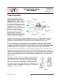
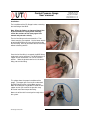
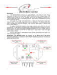
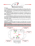
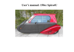
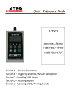
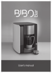
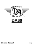
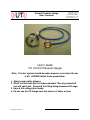
TM
Control Pressure Gauge
User’s manual
UnwiredTools, LLC
2200 East Cedar #1
Flagstaff, AZ 860004
www.unwiredtools.com
[email protected]
User’s Guide
For Control Pressure Gauge
Note: The fuel system should be under pressure even when the car
is off. ALWAYS follow these precautions:
1. Always wear safety glasses.
2. When the fuel lines are first loosened about 10cc of pressurized
fuel will squirt out. Surround the fitting being loosened with rags.
3. Have a fire extinguisher handy.
4. Do not use the CP Gauge near any source of flame or heat.
CP Gauge manual A1
1
TM
Control Pressure Gauge
User’s manual
UnwiredTools, LLC
2200 East Cedar #1
Flagstaff, AZ 860004
www.unwiredtools.com
[email protected]
Printed in the U.S.A.
Copyright © 2008 UnwiredTools, LLC
All Rights Reserved.
NOTICE REGARDING WARRANTIES
The UnwiredTools™ CP gauge does not warrant for any aspect of its use, fitness for use, suitability, or
safety for any purpose whatsoever. The user assumes all risk and responsibility for use of the CP
Gauge.
The information in this Manual therefore is provided as a general guide or illustration. It is your
responsibility and not that of UnwiredTools to ensure that this Product is suitable for your vehicle and
that it meets your needs or requirements. This Manual is provided “as is” and without any warranties of
any kind. UnwiredTools makes no representations or warranties with respect to this Manual, e.g., as to
its accuracy, completeness or appropriateness to any particular vehicle or situation. UNWIREDTOOLS
HEREBY DISCLAIMS ANY AND ALL WARRANTIES AS TO THIS MANUAL, EXPRESS OR IMPLIED,
INCLUDING BUT NOT LIMITED TO THE IMPLIED WARRANTIES OF MERCHANTABILITY AND
FITNESS FOR A PARTICULAR PURPOSE. UNWIREDTOOLS ALSO DISCLAIMS ANY LIABILITY
FOR YOUR USE OF THE MANUAL. PLEASE USE IT AT YOUR OWN RISK. This Manual may be
updated from time to time. Users are encouraged to visit our Web site at www.unwiredtools.com to
obtain the latest version, to obtain information about the Product, and to obtain other support
information.
CP Gauge manual A1
2
TM
Control Pressure Gauge
User’s manual
UnwiredTools, LLC
2200 East Cedar #1
Flagstaff, AZ 860004
www.unwiredtools.com
[email protected]
Theory of Operation
The Bosch CIS mechanical fuel
injection system works by converting
the flow of intake air into a precisely
metered flow of fuel. Figure 1 shows a
VW fuel distributor where the air moves
up to move the Sensor plate. On most
Mercedes and Porsche applications the
airflow direction is down but the
principle is the same. When the Sensor
plate moves the Main lever moves,
which in turn pushes the Control
plunger up and down. The Control
plunger uncovers a set of finely
machined narrow slits, one per cylinder.
Fuel flows to the injectors through the
port on top, shown as A in Figure 1.
Figure 1
The force which moves the Sensor plate is the flow of a mass of air. This force moves the Control
plunger up. There is an opposing force which pushes the Control plunger back down. This force is
exerted on the Control plunger by a special hydraulic pressure called the Control Pressure.
The name Control Pressure means the pressure used to control the air/fuel ratio. When the Control
Pressure is low, the force pushing against the Control plunger is low, allowing the Control plunger to
travel further and thereby delivering more fuel. This richens the mixture. For this reason a low control
pressure richens the air/fuel mixture, while a high control pressure leans out the mixture.
The injection system has to change the mixture depending of a number of factors. When the engine is
cold the mixture must be very rich. When the engine is fully warm and idling the mixture is slightly lean.
Under maximum acceleration the mixture richens slightly. These changes to the mixture are handled by
one very critical component of the system called the Warm-Up Regulator (WUR). The WUR handles far
more than just operation during warm-up. The WUR handles setting the mixture during all phases of
engine operation.
The WUR is a complex, imprecise, and relatively fragile component.
Many problems like hard starting, poor mileage, and lack of power
can be traced to the WUR. Fortunately the operation of the WUR is
easy to check, if you have a gauge which can measure the control
pressure. The gauge must measure the pressure between the port
at the center top of the fuel distributor and the inlet of the WUR. The
inlet port of the WUR is the larger of the two fittings. The connection
of the gauge is shown in Figure 2.
Figure 2
CP Gauge manual A1
3
TM
Control Pressure Gauge
User’s manual
UnwiredTools, LLC
2200 East Cedar #1
Flagstaff, AZ 860004
www.unwiredtools.com
[email protected]
Installation:
The installation of the CP Gauge involves removing
the inlet fitting of the WUR.
Note: When the fittings are loosened about 10cc
of pressurized fuel is sprayed out. Carefully
review the cautions on the front page of this
manual and proceed carefully.
The fuel line fitting must be removed first. Two
14mm wrenches are required. Use the lower wrench
to hold the WUR fitting in place while loosening the
fuel line fitting. Don’t try to remove the fuel line fitting
without a backing wrench.
Once the fuel line fitting is removed. the WUR fitting
underneath can be removed. The WUR fitting has a
copper washer underneath. Be sure to save this
washer. Note: the photo shown here is the outlet
fitting, not the inlet fitting.
This photo shows the proper installation of the
gauge. The copper pressure ring fits underneath
the WUR fitting just like a thick copper washer.
Note: when fitting the ring do NOT include the thin
copper washer you saved in the previous step.
Be careful not to over-torque the fitting.
Now re-install the fuel line and you’re ready to test
the system.
CP Gauge manual A1
4
TM
Control Pressure Gauge
User’s manual
UnwiredTools, LLC
2200 East Cedar #1
Flagstaff, AZ 860004
www.unwiredtools.com
[email protected]
Starting, monitoring, troubleshooting:
Start the car and check carefully for leaks around the CP gauge fittings. As soon as
the engine starts you can read the control pressure.
UnwiredTools has an extensive database of control pressures for every phase of
operation of cars equipped with CIS fuel injection. Contact us for detailed
specifications.
For a quick but effective test, the control pressures should be as follows:
Cold Start, 60°F
1.6bar (24psi)
Cold Start, 80°F
2.2bar (32psi)
Engine fully warm, idling, vacuum line attached
Engine idling, remove vacuum line
3.4bar (50psi)
3.0bar (44psi)
The values above may differ from your test values. The most important factor is that
the control pressure should change as indicated. For example, you should be able to
see the control pressure increase after a cold start.
Note: Some flutter of the control pressure at idle is normal. If the flutter exceeds 5psi
then the fuel accumulator may be defective. The gauge may be easier to read if the
engine speed is raised slightly above idle, i.e. 1200 RPM.
CP Gauge manual A1
5